Control4 CXMRCR11 Wireless Contact/Relay Extender Model CXM-RCR1-B User Manual WirelessContact RelayExtender
Control4 Wireless Contact/Relay Extender Model CXM-RCR1-B WirelessContact RelayExtender
UserManual.wiki
>
Control4
>
CXMRCR11 User Manual
Exhibit 8
Navigation menu
Upload a User Manual
Namespaces
Wiki Guide
HTML
PDF
Info
Views
User Manual
Discussion / Help
Navigation
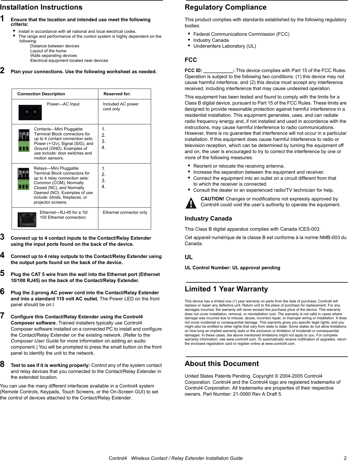
![Control4 Wireless Contact / Relay Extender Installation Guide 1 Wireless Contact / Relay Extender Installation GuideFeaturesThe Wireless Contact/Relay Extender is intended for use as a device you can control with your Control4® system. It is for the user who is looking for ways to control contact or relay devices in areas away from the main controller or who is simply looking for additional contacts and/or relays. When installed, the Contact/Relay Extender is physically connected to up to four contacts and/or four relays and communicates to the Control4 system using either an Ethernet connection or a ZigBee (wireless) connection.The Contact/Relay Extender is designed to sit on a standard rack shelf rather than be mounted with traditional rack ears. Its approximate dimensions are 6.5” wide (1/2 RU) x 1.5” tall (just under 1 RU) x 7.0” deep and it comes with a small plastic rack that enables you to store it in a vertical position.WARNING! To reduce the risk of serious injury or death, turn all power OFF before installing this product. WARNING! Do NOT use this device to control a non-dimmable load.WARNING! This product generates heat. The device must be operated within specified operating temperature limits.Using this product in a manner other than outlined in this document voids your warranty. Further, Control4 is NOT liable for any damage incurred with the misuse of this product. See “Limited 1 Year Warranty.” Requirements Specifications???What’s in the Box•Control4 Wireless Contact/Relay Extender •AC power cord (2-prong)•Vertical Mount Bracket •Wireless Contact / Relay Extender Installation Guide (this guide)About the HardwareFront PanelThe front panel of the Contact/Relay Extender has three red LEDs indicating power and network connection status for Ethernet and ZigBee. A small button on the front panel enables you to identify the unit to the network during setup.....and it acts as a “reset” when pressed for 10 seconds. [Reset not currently supported...Should it be?]1. Ethernet LED:• Flashing = Searching for an Ethernet link• On = Ethernet link established2. ZigBee LED: • Flashing = Searching for a ZigBee link• On = ZigBee link established3. Power LED:• On = Power present4. ID Button: • When appropriate during system setup, press to uniquely identify this Contact/Relay Extender to the network. Or, when a reset is needed, press and hold for 10 seconds. [Reset not currently supported...Should it be?]Back PanelBecome familiar with the back panel of the Wireless Contact/Relay Extender. 1. Power plug port—For supplied power cord only.2. Contacts 1-4—Plugable Terminal Block connector for up to four dry con-tact closure, or logic input connections, such as door switches or motion sensors.3. Relays 1-4—Plugable Terminal Block connector for up to four normally closed or normally opened switchable connections, such as blinds, fire-place, or projector screens.4. Ethernet—RJ-45 for a 10/100 Ethernet connection.Models: CXM-RCR1-B Wireless Contact / Relay Extender (802.15.4)Power: _____VAC 50/60 Hz_____W Communications: ZigBee (802.15.4)10/100 Ethernet 1 2 3 4 1 2 3 4](https://usermanual.wiki/Control4/CXMRCR11/User-Guide-536570-Page-1.png)