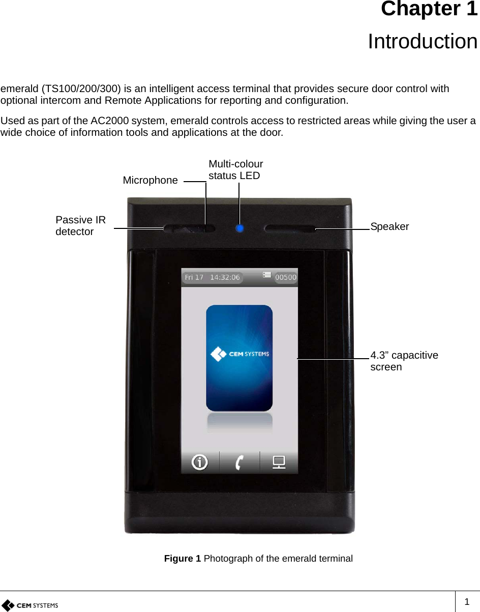
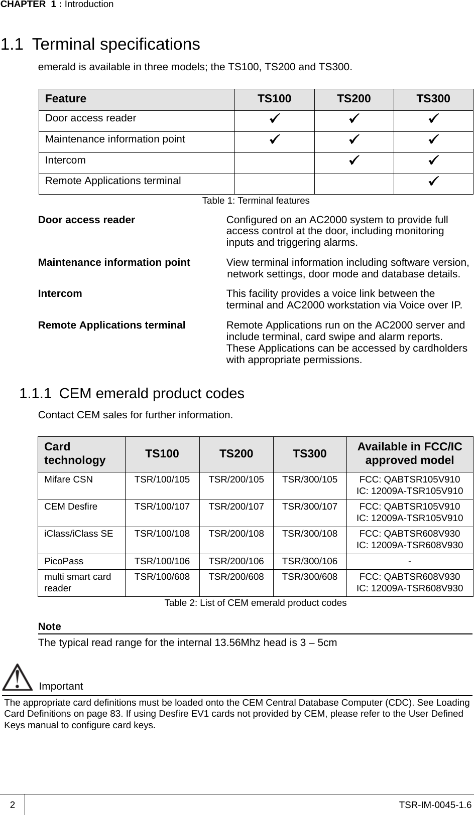
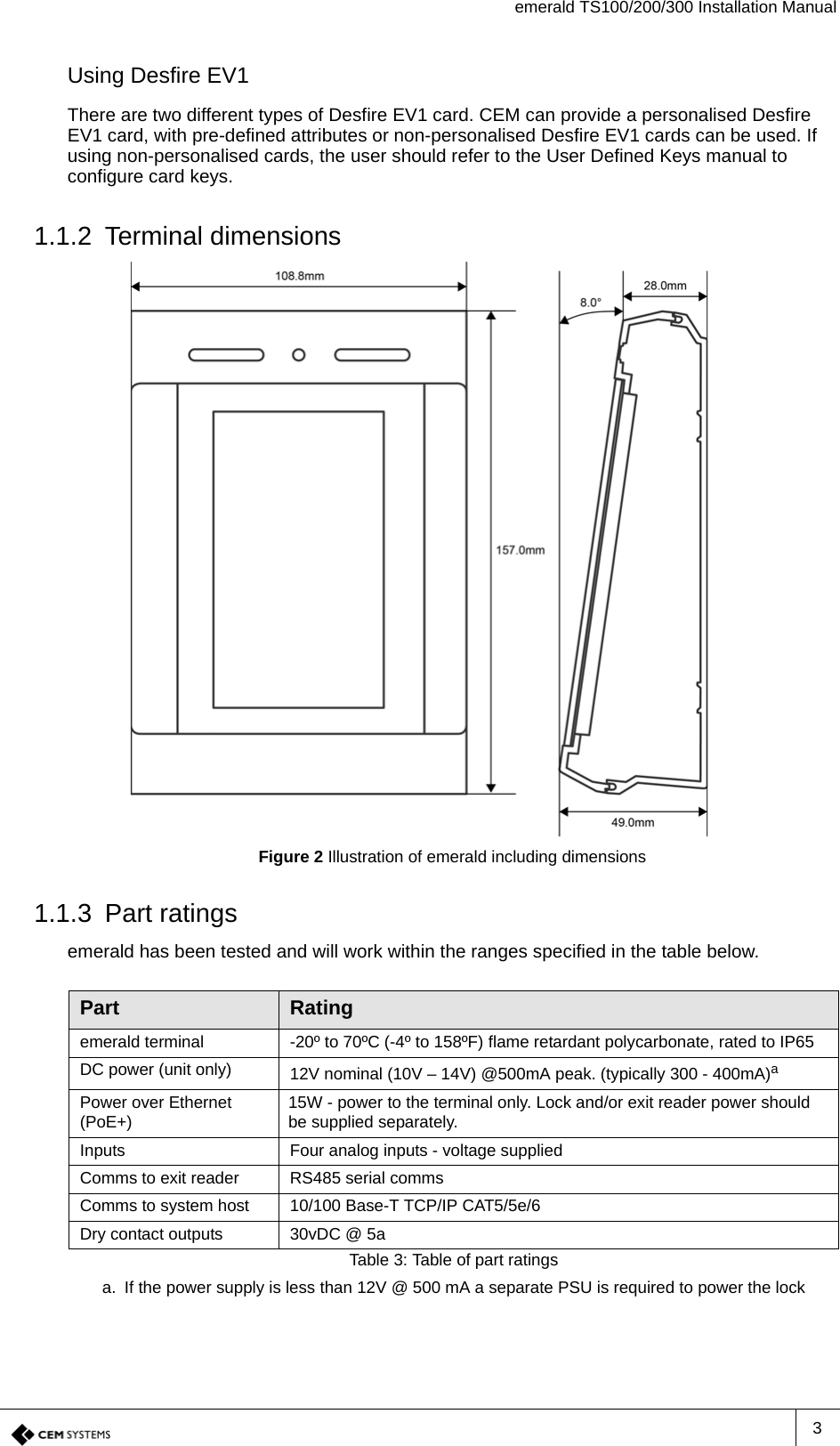
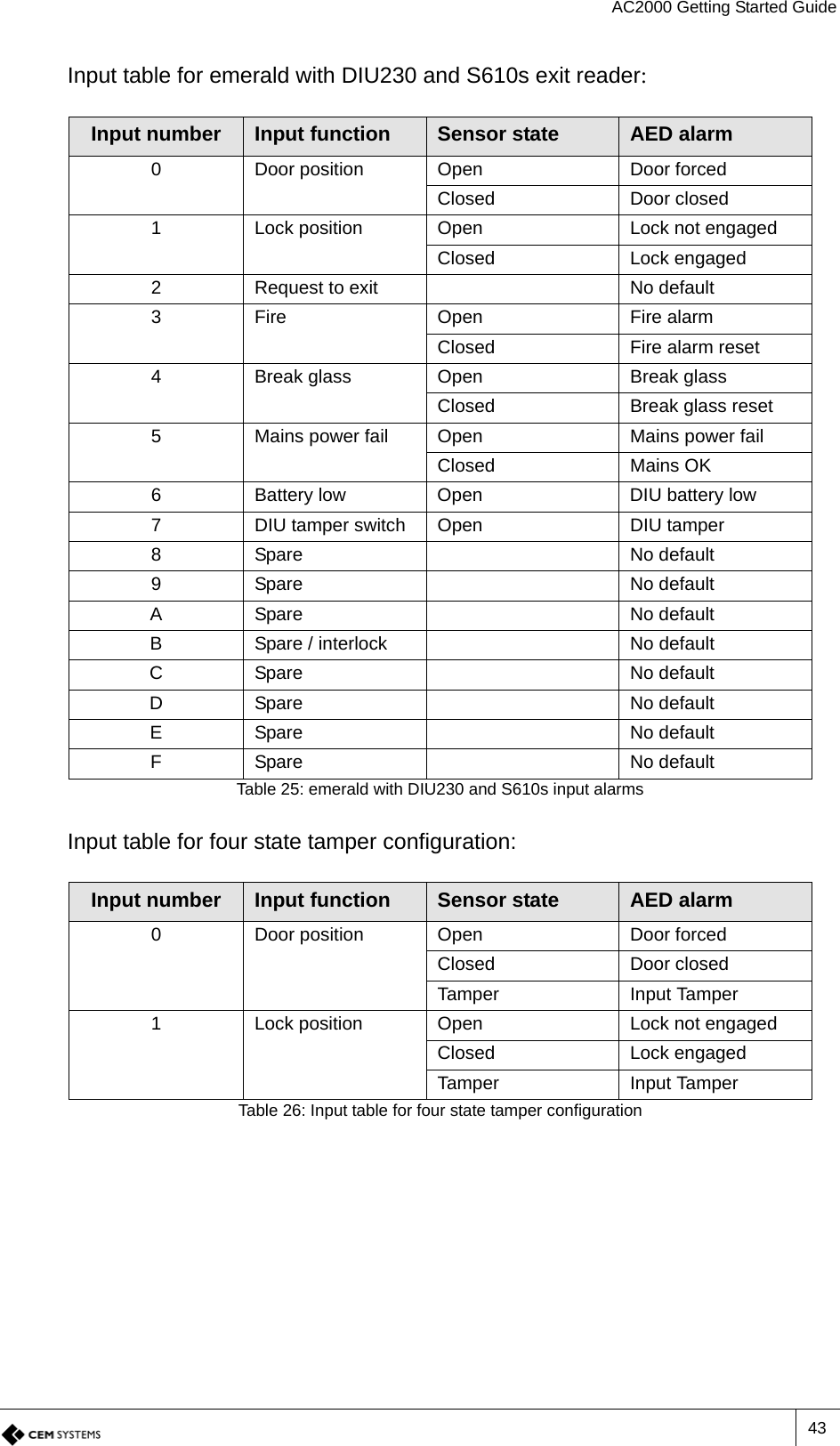
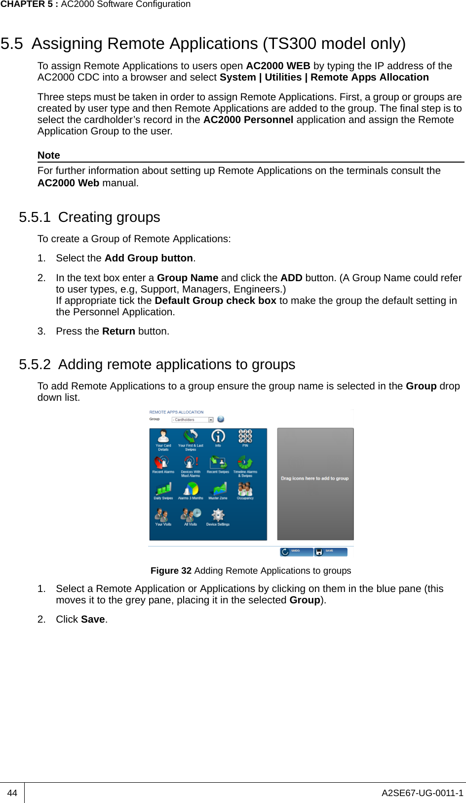
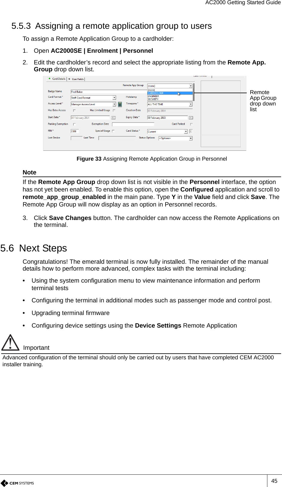
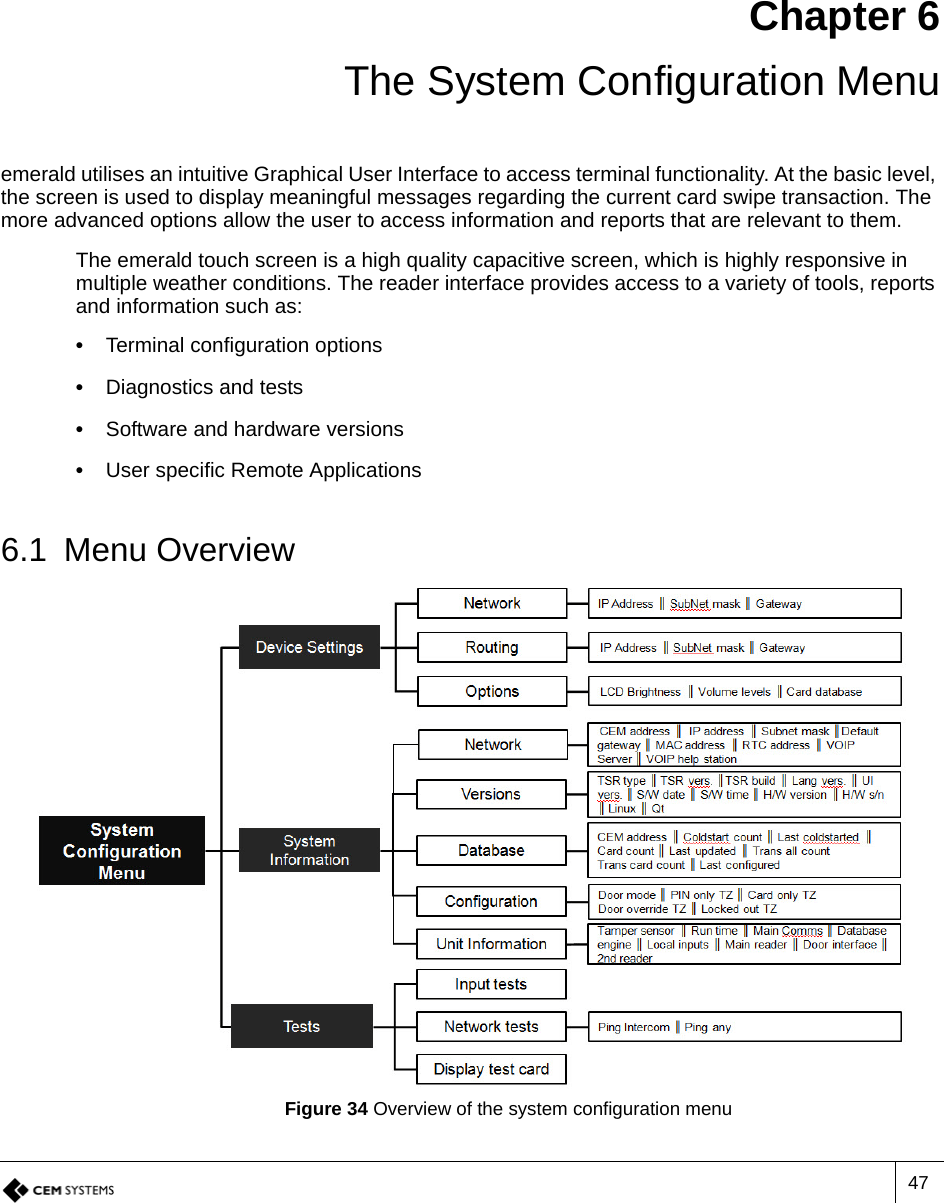
Controlled Electronic Management Systems TSR608V930 Emerald TM multi smart card reader User Manual
Controlled Electronic Management Systems Ltd Emerald TM multi smart card reader Users Manual
UserManual.wiki
>
Controlled Electronic Management Systems
>
TSR608V930 User Manual
Users Manual
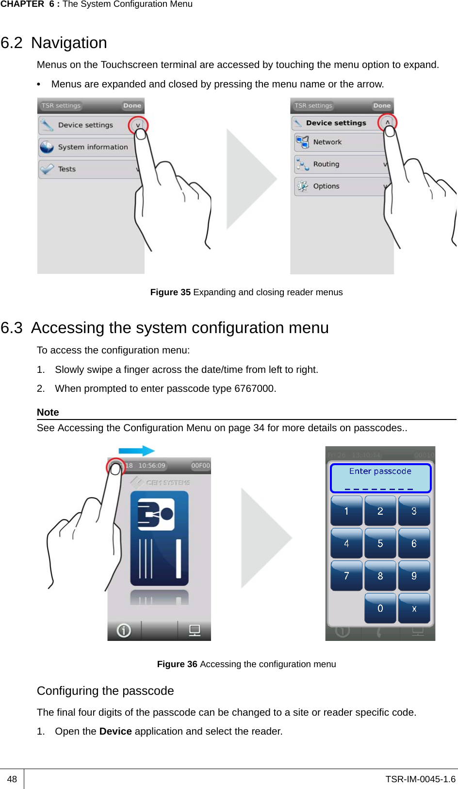
Navigation menu
Upload a User Manual
Namespaces
Wiki Guide
HTML
PDF
Info
Views
User Manual
Discussion / Help
Navigation