Controlled Electronic Management Systems TSR608V930 Emerald TM multi smart card reader User Manual
Controlled Electronic Management Systems Ltd Emerald TM multi smart card reader Users Manual
Users Manual

TSR-IM-0045-1.6
emerald TS100/200/300
Installation Manual
Notice
The information in this manual was current when published. The manufacturer reserves the right to revise and
improve its products. All specifications are therefore subject to change without notice.
Copyright
Under copyright laws, the contents of this manual may not be copied, photocopied, reproduced, translated or reduced
to any electronic medium or machine-readable form, in whole or in part, without prior written consent of © 2013 Tyco
Security Products. All Rights Reserved.
Trademarks
The trademarks, logos, and service marks displayed on this document are registered in the United States (or other
countries). Any misuse of the trademarks is strictly prohibited and Tyco Security Products will aggressively enforce its
intellectual property rights to the fullest extent of the law, including pursuit of criminal prosecution wherever necessary.
All trademarks not owned by Tyco Security Products are the property of their respective owners, and are used with
permission or allowed under applicable laws.
Product offerings and specifications are subject to change without notice. Actual products may vary from photos. Not
all products include all features. Availability varies by region. Contact your sales representative for more information.
Licence information
Your use of this product is governed by certain terms and conditions.
Support
If you require technical assistance using CEM products, please contact the CEM Support team using the following
telephone number:
Telephone:+44(0)2890 456656
Email: cem.support@tycoint.com
• Please provide our support engineers with as much information as possible. This may include:
• Site name
• Product name and model
• CEM software version
• Description of the problem
Publication Date
31st May 2014

emerald TS100/200/300 Installation Manual
iii
Warning
This is a class A product. In a domestic environment this product may cause radio interference in which case the user
may be required to take adequate measures
Warning
English
Under Industry Canada regulations, this radio transmitter may only operate using an antenna of a type and maximum
(or lesser) gain approved for the transmitter by Industry Canada.
To reduce potential radio interference to other users, the antenna type and its gain should be so chosen that the
equivalent isotropically radiated power (e.i.r.p.) is not more than that necessary for successful communication.
This device complies with Industry Canada licence-exempt RSS standard(s). Operation is subject to the following two
conditions: (1) this device may not cause interference, and (2) this device must accept any interference, including
interference that may cause undesired operation of the device.
French
Conformément à la réglementation d'Industrie Canada, le présent émetteur radio peut fonctionner avec une antenne
d'un type et d'un gain maximal (ou inférieur) approuvé pour l'émetteur par Industrie Canada.
Dans le but de réduire les risques de brouillage radioélectrique à l'intention des autres utilisateurs, il faut choisir le type
d'antenne et son gain de sorte que la puissance isotrope rayonnée équivalente (p.i.r.e.) ne dépasse pas l'intensité
nécessaire à l'établissement d'une communication satisfaisante.
Le présent appareil est conforme aux CNR d'Industrie Canada applicables aux appareils radio exempts de licence.
L'exploitation est autorisée aux deux conditions suivantes : (1) l'appareil ne doit pas produire de brouillage, et (2)
l'utilisateur de l'appareil doit accepter tout brouillage radioélectrique subi, même si le brouillage est susceptible d'en
compromettre le fonctionnement.
Warning - For FCC Labelled emerald Terminals
This device complies with Part 15 of the FCC rules. Operation is subject to the following two conditions:
(1) This device may not cause harmful interference, and
(2) This device must accept an interference received, including interference that may cause undesired operation.
This equipment complies with FCC radiation exposure limits set forth for an uncontrolled environment. End users must
follow the specific operating instructions for satisfying RF exposure compliance. This transmitter must not be co-
located or operating in conjunction with any other antenna or transmitter.
Changes or modifications not expressly approved by the party responsible for compliance could void the user's
authority to operate the equipment.
Installation of this device shall be performed by a qualified person in accordance to all local regulations.
This system must be installed within the protected premise in accordance with the National Electrical Code (NFPA70),
and the local authorities having jurisdiction.
Equipment changes or modifications without the approval of the party responsible for compliance could void the user's
authority to operate the equipment and could create a hazardous condition.

TSR-IM-0045-1.6
CHAPTER 1 :
iv
Contents
1. Introduction . . . . . . . . . . . . . . . . . . . . . . . . . . . . . . . . . . . . . . . . . . . . . . . . . . . . . . . .1
Terminal specifications . . . . . . . . . . . . . . . . . . . . . . . . . . . . . . . . . . . . . . . . . . . . . . . . . . . . . . . . . . . . .2
CEM emerald product codes. . . . . . . . . . . . . . . . . . . . . . . . . . . . . . . . . . . . . . . . . . . . . . . . . . . . . . .2
Terminal dimensions . . . . . . . . . . . . . . . . . . . . . . . . . . . . . . . . . . . . . . . . . . . . . . . . . . . . . . . . . . . . .3
Part ratings . . . . . . . . . . . . . . . . . . . . . . . . . . . . . . . . . . . . . . . . . . . . . . . . . . . . . . . . . . . . . . . . . . . .3
Onboard memory . . . . . . . . . . . . . . . . . . . . . . . . . . . . . . . . . . . . . . . . . . . . . . . . . . . . . . . . . . . . . . .4
Terminal key component parts . . . . . . . . . . . . . . . . . . . . . . . . . . . . . . . . . . . . . . . . . . . . . . . . . . . . .5
Simplified AC2000 Network Topology . . . . . . . . . . . . . . . . . . . . . . . . . . . . . . . . . . . . . . . . . . . . . . . . . .6
Hardware Installation Process . . . . . . . . . . . . . . . . . . . . . . . . . . . . . . . . . . . . . . . . . . . . . . . . . . . . . . . .7
2. Mounting the Terminal. . . . . . . . . . . . . . . . . . . . . . . . . . . . . . . . . . . . . . . . . . . . . . . .9
Preparing for mounting . . . . . . . . . . . . . . . . . . . . . . . . . . . . . . . . . . . . . . . . . . . . . . . . . . . . . . . . . . . . .9
Recommended tools . . . . . . . . . . . . . . . . . . . . . . . . . . . . . . . . . . . . . . . . . . . . . . . . . . . . . . . . . . . . .9
Opening the terminal. . . . . . . . . . . . . . . . . . . . . . . . . . . . . . . . . . . . . . . . . . . . . . . . . . . . . . . . . . . .10
Mounting the terminal back casing . . . . . . . . . . . . . . . . . . . . . . . . . . . . . . . . . . . . . . . . . . . . . . . . .11
3. Wiring the Terminal . . . . . . . . . . . . . . . . . . . . . . . . . . . . . . . . . . . . . . . . . . . . . . . . .13
Cabling requirements. . . . . . . . . . . . . . . . . . . . . . . . . . . . . . . . . . . . . . . . . . . . . . . . . . . . . . . . . . . . . .13
Ethernet host. . . . . . . . . . . . . . . . . . . . . . . . . . . . . . . . . . . . . . . . . . . . . . . . . . . . . . . . . . . . . . . . . .13
The Front Board. . . . . . . . . . . . . . . . . . . . . . . . . . . . . . . . . . . . . . . . . . . . . . . . . . . . . . . . . . . . . . . . . .14
The Input/Output Board . . . . . . . . . . . . . . . . . . . . . . . . . . . . . . . . . . . . . . . . . . . . . . . . . . . . . . . . . . . .15
Wiring locks . . . . . . . . . . . . . . . . . . . . . . . . . . . . . . . . . . . . . . . . . . . . . . . . . . . . . . . . . . . . . . . . . . . . .16
Wiring a voltage provided lock (internal power) . . . . . . . . . . . . . . . . . . . . . . . . . . . . . . . . . . . . . . .16
Wiring a voltage not provided lock (external power) . . . . . . . . . . . . . . . . . . . . . . . . . . . . . . . . . . . .17
Output power switch . . . . . . . . . . . . . . . . . . . . . . . . . . . . . . . . . . . . . . . . . . . . . . . . . . . . . . . . . . . .17
Inputs not in use . . . . . . . . . . . . . . . . . . . . . . . . . . . . . . . . . . . . . . . . . . . . . . . . . . . . . . . . . . . . . . .17
Terminal with Request to Exit Switch. . . . . . . . . . . . . . . . . . . . . . . . . . . . . . . . . . . . . . . . . . . . . . . . . .18
Configuration information. . . . . . . . . . . . . . . . . . . . . . . . . . . . . . . . . . . . . . . . . . . . . . . . . . . . . . . . . . .19
Terminal with 3rd Party Wiegand Read Head . . . . . . . . . . . . . . . . . . . . . . . . . . . . . . . . . . . . . . . . . . .20
Configuration information. . . . . . . . . . . . . . . . . . . . . . . . . . . . . . . . . . . . . . . . . . . . . . . . . . . . . . . . . . .21
Terminal with S610s Exit Reader. . . . . . . . . . . . . . . . . . . . . . . . . . . . . . . . . . . . . . . . . . . . . . . . . . . . .22
Configuration information . . . . . . . . . . . . . . . . . . . . . . . . . . . . . . . . . . . . . . . . . . . . . . . . . . . . . . . .23
Terminal with DIU 210 . . . . . . . . . . . . . . . . . . . . . . . . . . . . . . . . . . . . . . . . . . . . . . . . . . . . . . . . . . . . 24
Configuration information . . . . . . . . . . . . . . . . . . . . . . . . . . . . . . . . . . . . . . . . . . . . . . . . . . . . . . . . 25
Terminal with DIU 230. . . . . . . . . . . . . . . . . . . . . . . . . . . . . . . . . . . . . . . . . . . . . . . . . . . . . . . . . . . . . 26
Configuration information . . . . . . . . . . . . . . . . . . . . . . . . . . . . . . . . . . . . . . . . . . . . . . . . . . . . . . . . 27
PoE+ Terminal with S610s Exit Reader . . . . . . . . . . . . . . . . . . . . . . . . . . . . . . . . . . . . . . . . . . . . . . . 28
Configuration . . . . . . . . . . . . . . . . . . . . . . . . . . . . . . . . . . . . . . . . . . . . . . . . . . . . . . . . . . . . . . . . . 29
Tamper Detection on Reader Inputs. . . . . . . . . . . . . . . . . . . . . . . . . . . . . . . . . . . . . . . . . . . . . . . . . . 30
Wiring the resistor network. . . . . . . . . . . . . . . . . . . . . . . . . . . . . . . . . . . . . . . . . . . . . . . . . . . . . . . 30
Configuring software for tamper detection . . . . . . . . . . . . . . . . . . . . . . . . . . . . . . . . . . . . . . . . . . . 30
Re-assembling the terminal . . . . . . . . . . . . . . . . . . . . . . . . . . . . . . . . . . . . . . . . . . . . . . . . . . . . . . 31
4. Reader Network Configuration. . . . . . . . . . . . . . . . . . . . . . . . . . . . . . . . . . . . . . . . 33
Checking emerald’s Network Status . . . . . . . . . . . . . . . . . . . . . . . . . . . . . . . . . . . . . . . . . . . . . . . . . . 33
Accessing the Configuration Menu . . . . . . . . . . . . . . . . . . . . . . . . . . . . . . . . . . . . . . . . . . . . . . . . . . . 34
Setting the terminal IP address, gateway and subnet mask . . . . . . . . . . . . . . . . . . . . . . . . . . . . . 34
Network routing - (advanced users) . . . . . . . . . . . . . . . . . . . . . . . . . . . . . . . . . . . . . . . . . . . . . . . . 35
Testing the connection with the AC2000 server. . . . . . . . . . . . . . . . . . . . . . . . . . . . . . . . . . . . . . . 35
5. AC2000 Software Configuration. . . . . . . . . . . . . . . . . . . . . . . . . . . . . . . . . . . . . . . 37
Reader Addressing . . . . . . . . . . . . . . . . . . . . . . . . . . . . . . . . . . . . . . . . . . . . . . . . . . . . . . . . . . . . . . . 37
Adding the device to AC2000 . . . . . . . . . . . . . . . . . . . . . . . . . . . . . . . . . . . . . . . . . . . . . . . . . . . . . . . 38
Configuring a 3rd party read head . . . . . . . . . . . . . . . . . . . . . . . . . . . . . . . . . . . . . . . . . . . . . . . . . 39
Configuring Device Inputs. . . . . . . . . . . . . . . . . . . . . . . . . . . . . . . . . . . . . . . . . . . . . . . . . . . . . . . . . . 40
Adding an input alarm . . . . . . . . . . . . . . . . . . . . . . . . . . . . . . . . . . . . . . . . . . . . . . . . . . . . . . . . . . 40
Configuring 4 state tamper inputs . . . . . . . . . . . . . . . . . . . . . . . . . . . . . . . . . . . . . . . . . . . . . . . . . 40
Editing emerald Entries in AC2000. . . . . . . . . . . . . . . . . . . . . . . . . . . . . . . . . . . . . . . . . . . . . . . . . . . 41
Editing device properties . . . . . . . . . . . . . . . . . . . . . . . . . . . . . . . . . . . . . . . . . . . . . . . . . . . . . . . . 41
Editing a device input . . . . . . . . . . . . . . . . . . . . . . . . . . . . . . . . . . . . . . . . . . . . . . . . . . . . . . . . . . . 41
Deleting a device input. . . . . . . . . . . . . . . . . . . . . . . . . . . . . . . . . . . . . . . . . . . . . . . . . . . . . . . . . . 41
Input alarms . . . . . . . . . . . . . . . . . . . . . . . . . . . . . . . . . . . . . . . . . . . . . . . . . . . . . . . . . . . . . . . . . . 41
Assigning Remote Applications (TS300 model only) . . . . . . . . . . . . . . . . . . . . . . . . . . . . . . . . . . . . . 44
Creating groups . . . . . . . . . . . . . . . . . . . . . . . . . . . . . . . . . . . . . . . . . . . . . . . . . . . . . . . . . . . . . . . 44
Adding remote applications to groups . . . . . . . . . . . . . . . . . . . . . . . . . . . . . . . . . . . . . . . . . . . . . . 44
Assigning a remote application group to users . . . . . . . . . . . . . . . . . . . . . . . . . . . . . . . . . . . . . . . .45
Next Steps . . . . . . . . . . . . . . . . . . . . . . . . . . . . . . . . . . . . . . . . . . . . . . . . . . . . . . . . . . . . . . . . . . . . . .45
6. The System Configuration Menu . . . . . . . . . . . . . . . . . . . . . . . . . . . . . . . . . . . . . .47
Menu Overview . . . . . . . . . . . . . . . . . . . . . . . . . . . . . . . . . . . . . . . . . . . . . . . . . . . . . . . . . . . . . . . . . .47
Navigation . . . . . . . . . . . . . . . . . . . . . . . . . . . . . . . . . . . . . . . . . . . . . . . . . . . . . . . . . . . . . . . . . . . . . .48
Accessing the system configuration menu. . . . . . . . . . . . . . . . . . . . . . . . . . . . . . . . . . . . . . . . . . . . . .48
Device settings menu . . . . . . . . . . . . . . . . . . . . . . . . . . . . . . . . . . . . . . . . . . . . . . . . . . . . . . . . . . .49
System Information menu . . . . . . . . . . . . . . . . . . . . . . . . . . . . . . . . . . . . . . . . . . . . . . . . . . . . . . . .52
Tests menu . . . . . . . . . . . . . . . . . . . . . . . . . . . . . . . . . . . . . . . . . . . . . . . . . . . . . . . . . . . . . . . . . . .54
7. Door Modes. . . . . . . . . . . . . . . . . . . . . . . . . . . . . . . . . . . . . . . . . . . . . . . . . . . . . . . .57
Door Mode . . . . . . . . . . . . . . . . . . . . . . . . . . . . . . . . . . . . . . . . . . . . . . . . . . . . . . . . . . . . . . . . . . . . . .57
Door mode timings . . . . . . . . . . . . . . . . . . . . . . . . . . . . . . . . . . . . . . . . . . . . . . . . . . . . . . . . . . . . .57
Multi-swipe access . . . . . . . . . . . . . . . . . . . . . . . . . . . . . . . . . . . . . . . . . . . . . . . . . . . . . . . . . . . . .58
Control Post Mode . . . . . . . . . . . . . . . . . . . . . . . . . . . . . . . . . . . . . . . . . . . . . . . . . . . . . . . . . . . . . . . .60
Software configuration for control post mode . . . . . . . . . . . . . . . . . . . . . . . . . . . . . . . . . . . . . . . . .60
Passenger Mode . . . . . . . . . . . . . . . . . . . . . . . . . . . . . . . . . . . . . . . . . . . . . . . . . . . . . . . . . . . . . . . . .61
Configuring passenger mode in the software . . . . . . . . . . . . . . . . . . . . . . . . . . . . . . . . . . . . . . . . .61
The passenger mode cycle . . . . . . . . . . . . . . . . . . . . . . . . . . . . . . . . . . . . . . . . . . . . . . . . . . . . . . .62
Lobby mode . . . . . . . . . . . . . . . . . . . . . . . . . . . . . . . . . . . . . . . . . . . . . . . . . . . . . . . . . . . . . . . . . .62
Interlock . . . . . . . . . . . . . . . . . . . . . . . . . . . . . . . . . . . . . . . . . . . . . . . . . . . . . . . . . . . . . . . . . . . . . . . .63
Wiring two terminals for interlock . . . . . . . . . . . . . . . . . . . . . . . . . . . . . . . . . . . . . . . . . . . . . . . . . .63
The interlock process in door mode . . . . . . . . . . . . . . . . . . . . . . . . . . . . . . . . . . . . . . . . . . . . . . . .65
The interlock process in passenger mode . . . . . . . . . . . . . . . . . . . . . . . . . . . . . . . . . . . . . . . . . . .65
Image on Swipe . . . . . . . . . . . . . . . . . . . . . . . . . . . . . . . . . . . . . . . . . . . . . . . . . . . . . . . . . . . . . . . . . .67
Enabling Image on swipe . . . . . . . . . . . . . . . . . . . . . . . . . . . . . . . . . . . . . . . . . . . . . . . . . . . . . . . .67
Configuring Image on swipe options . . . . . . . . . . . . . . . . . . . . . . . . . . . . . . . . . . . . . . . . . . . . . . . .68
Random checks . . . . . . . . . . . . . . . . . . . . . . . . . . . . . . . . . . . . . . . . . . . . . . . . . . . . . . . . . . . . . . .70
Checking the firmware version of the terminal . . . . . . . . . . . . . . . . . . . . . . . . . . . . . . . . . . . . . . . .73
Loading the firmware onto the terminal(s). . . . . . . . . . . . . . . . . . . . . . . . . . . . . . . . . . . . . . . . . . . .73
Updating the terminal . . . . . . . . . . . . . . . . . . . . . . . . . . . . . . . . . . . . . . . . . . . . . . . . . . . . . . . . . . .74
Appendix I: Device Settings Remote Application . . . . . . . . . . . . . . . . . . . . . . . . . .75
Using the Application . . . . . . . . . . . . . . . . . . . . . . . . . . . . . . . . . . . . . . . . . . . . . . . . . . . . . . . . . . .75
Configuring the options . . . . . . . . . . . . . . . . . . . . . . . . . . . . . . . . . . . . . . . . . . . . . . . . . . . . . . . . . 76
Appendix II: Broadcast and Timezone Priorities . . . . . . . . . . . . . . . . . . . . . . . . . . . 81
Appendix III: Loading Card Definitions. . . . . . . . . . . . . . . . . . . . . . . . . . . . . . . . . . . 83
Appendix IV: Configuring a Third Party Reader as a Master . . . . . . . . . . . . . . . . . 85
Appendix V: User Defined Logo. . . . . . . . . . . . . . . . . . . . . . . . . . . . . . . . . . . . . . . . . 87
Licensing the emerald logo change function . . . . . . . . . . . . . . . . . . . . . . . . . . . . . . . . . . . . . . . . . 87
Enabling the emerald logo change function on the CDC . . . . . . . . . . . . . . . . . . . . . . . . . . . . . . . . 88
Uploading a user defined Card Logo in AC2000 WEB. . . . . . . . . . . . . . . . . . . . . . . . . . . . . . . . . . 88
1
Chapter 1
Introduction
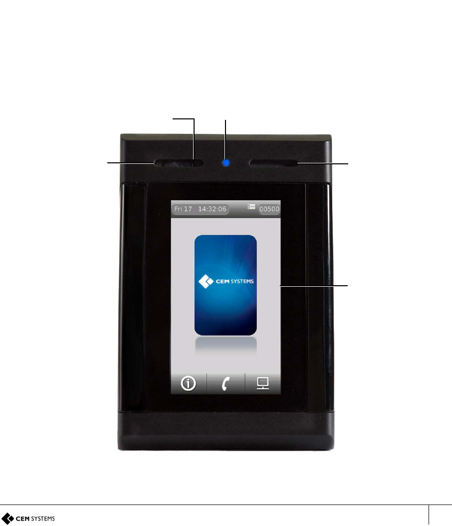
emerald (TS100/200/300) is an intelligent access terminal that provides secure door control with
optional intercom and Remote Applications for reporting and configuration.
Used as part of the AC2000 system, emerald controls access to restricted areas while giving the user a
wide choice of information tools and applications at the door.
Figure 1 Photograph of the emerald terminal
Multi-colour
status LED
Passive IR
detector Speaker
4.3” capacitive
screen
Microphone
TSR-IM-0045-1.6
CHAPTER 1 : Introduction
2
1.1 Terminal specifications
emerald is available in three models; the TS100, TS200 and TS300.
Door access reader Configured on an AC2000 system to provide full
access control at the door, including monitoring
inputs and triggering alarms.
Maintenance information point View terminal information including software version,
network settings, door mode and database details.
Intercom This facility provides a voice link between the
terminal and AC2000 workstation via Voice over IP.
Remote Applications terminal Remote Applications run on the AC2000 server and
include terminal, card swipe and alarm reports.
These Applications can be accessed by cardholders
with appropriate permissions.
1.1.1 CEM emerald product codes
Contact CEM sales for further information.
Note
The typical read range for the internal 13.56Mhz head is 3 – 5cm
Important
The appropriate card definitions must be loaded onto the CEM Central Database Computer (CDC). See Loading
Card Definitions on page 83. If using Desfire EV1 cards not provided by CEM, please refer to the User Defined
Keys manual to configure card keys.
Feature TS100 TS200 TS300
Door access reader
Maintenance information point
Intercom
Remote Applications terminal
Table 1: Terminal features
Card
technology TS100 TS200 TS300 Available in FCC/IC
approved model
Mifare CSN TSR/100/105 TSR/200/105 TSR/300/105 FCC: QABTSR105V910
IC: 12009A-TSR105V910
CEM Desfire TSR/100/107 TSR/200/107 TSR/300/107 FCC: QABTSR105V910
IC: 12009A-TSR105V910
iClass/iClass SE TSR/100/108 TSR/200/108 TSR/300/108 FCC: QABTSR608V930
IC: 12009A-TSR608V930
PicoPass TSR/100/106 TSR/200/106 TSR/300/106 -
multi smart card
reader TSR/100/608 TSR/200/608 TSR/300/608 FCC: QABTSR608V930
IC: 12009A-TSR608V930
Table 2: List of CEM emerald product codes
emerald TS100/200/300 Installation Manual
3
Using Desfire EV1
There are two different types of Desfire EV1 card. CEM can provide a personalised Desfire
EV1 card, with pre-defined attributes or non-personalised Desfire EV1 cards can be used. If
using non-personalised cards, the user should refer to the User Defined Keys manual to
configure card keys.
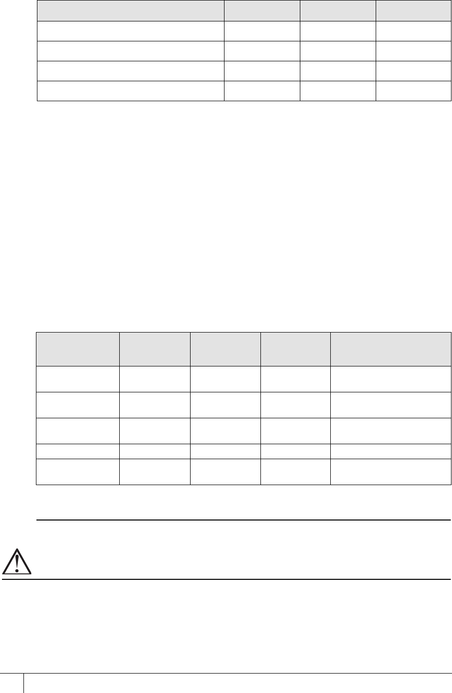
1.1.2 Terminal dimensions
Figure 2 Illustration of emerald including dimensions
1.1.3 Part ratings
emerald has been tested and will work within the ranges specified in the table below.
Part Rating
emerald terminal -20º to 70ºC (-4º to 158ºF) flame retardant polycarbonate, rated to IP65
DC power (unit only) 12V nominal (10V – 14V) @500mA peak. (typically 300 - 400mA)a
a. If the power supply is less than 12V @ 500 mA a separate PSU is required to power the lock
Power over Ethernet
(PoE+) 15W - power to the terminal only. Lock and/or exit reader power should
be supplied separately.
Inputs Four analog inputs - voltage supplied
Comms to exit reader RS485 serial comms
Comms to system host 10/100 Base-T TCP/IP CAT5/5e/6
Dry contact outputs 30vDC @ 5a
Table 3: Table of part ratings

TSR-IM-0045-1.6
CHAPTER 1 : Introduction
4
1.1.4 Onboard memory
128MB RAM, 256MB NAND Flash
• Up to 250,000 cardholder records (off-line)
• Up to 50,000 transactions (off-line)
emerald TS100/200/300 Installation Manual
5
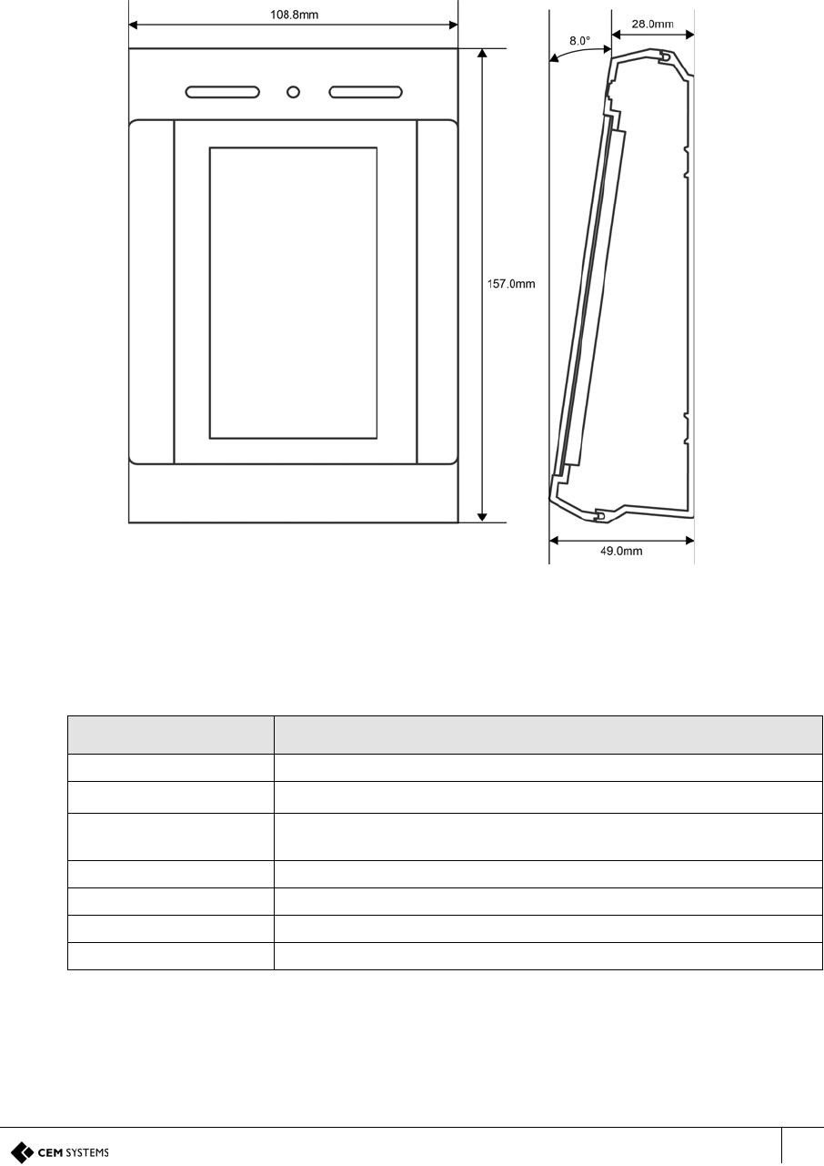
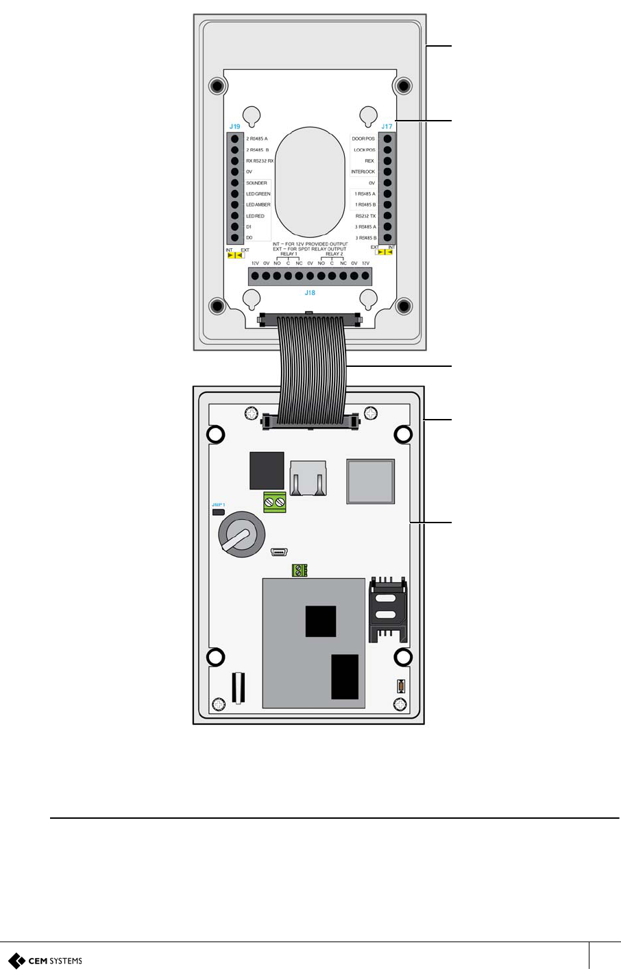
1.1.5 Terminal key component parts
Figure 3 Illustration of the key component parts
Note
All emerald models use the same component parts.
Back casing
I/O board
Ribbon cable
Front casing
Front board
Back
Front
TSR-IM-0045-1.6
CHAPTER 1 : Introduction
6
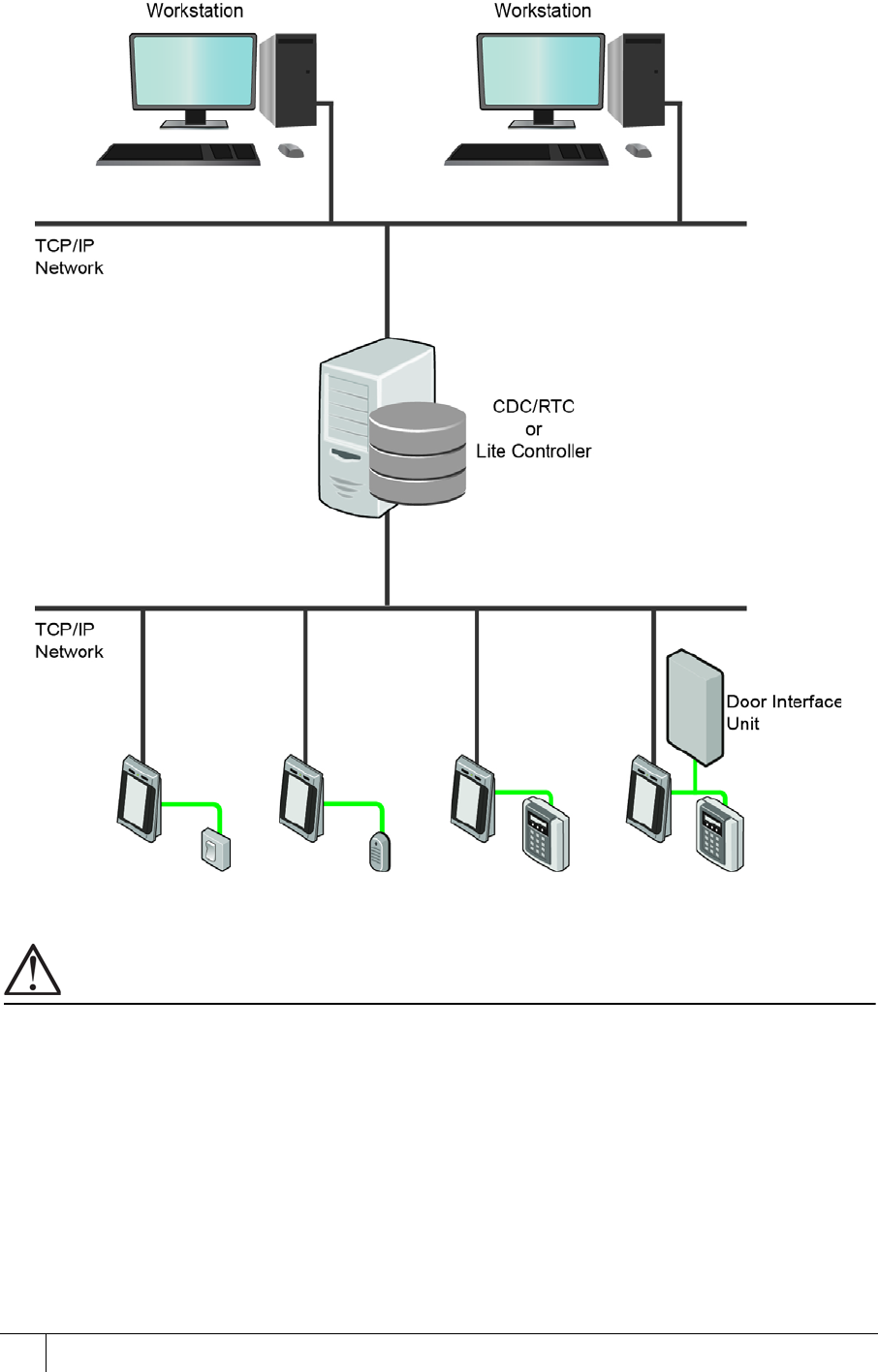
1.2 Simplified AC2000 Network Topology
Figure 4 Basic illustration of a typical AC2000 network including emerald configurations
Important
The emerald terminal is only available as an ethernet device.
emerald TS100/200/300 Installation Manual
7
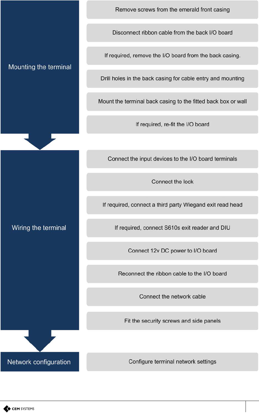
1.3 Hardware Installation Process
Figure 5 Hardware installation flow chart

TSR-IM-0045-1.6
CHAPTER 1 : Introduction
8
9
Chapter 2
Mounting the Terminal
The emerald terminal can be mounted on a variety of standard electrical back boxes:
• UK single back box
• US single back box
• UK double back box mounted vertically
• 75mm VESA mount
2.1 Preparing for mounting
Care must be taken with the internal components when disassembling the terminal.
2.1.1 Recommended tools
• 3 mm flat head screwdriver for input / output connections and DC power
• Wire cutters and strippers
• Security hex screwdriver
Product CEM Product Code
Security screw driver handle HTO/000/001
Security screw driver bit HTO/000/000
Table 4: Security screwdriver product codes
TSR-IM-0045-1.6
CHAPTER 2 : Mounting the Terminal
10
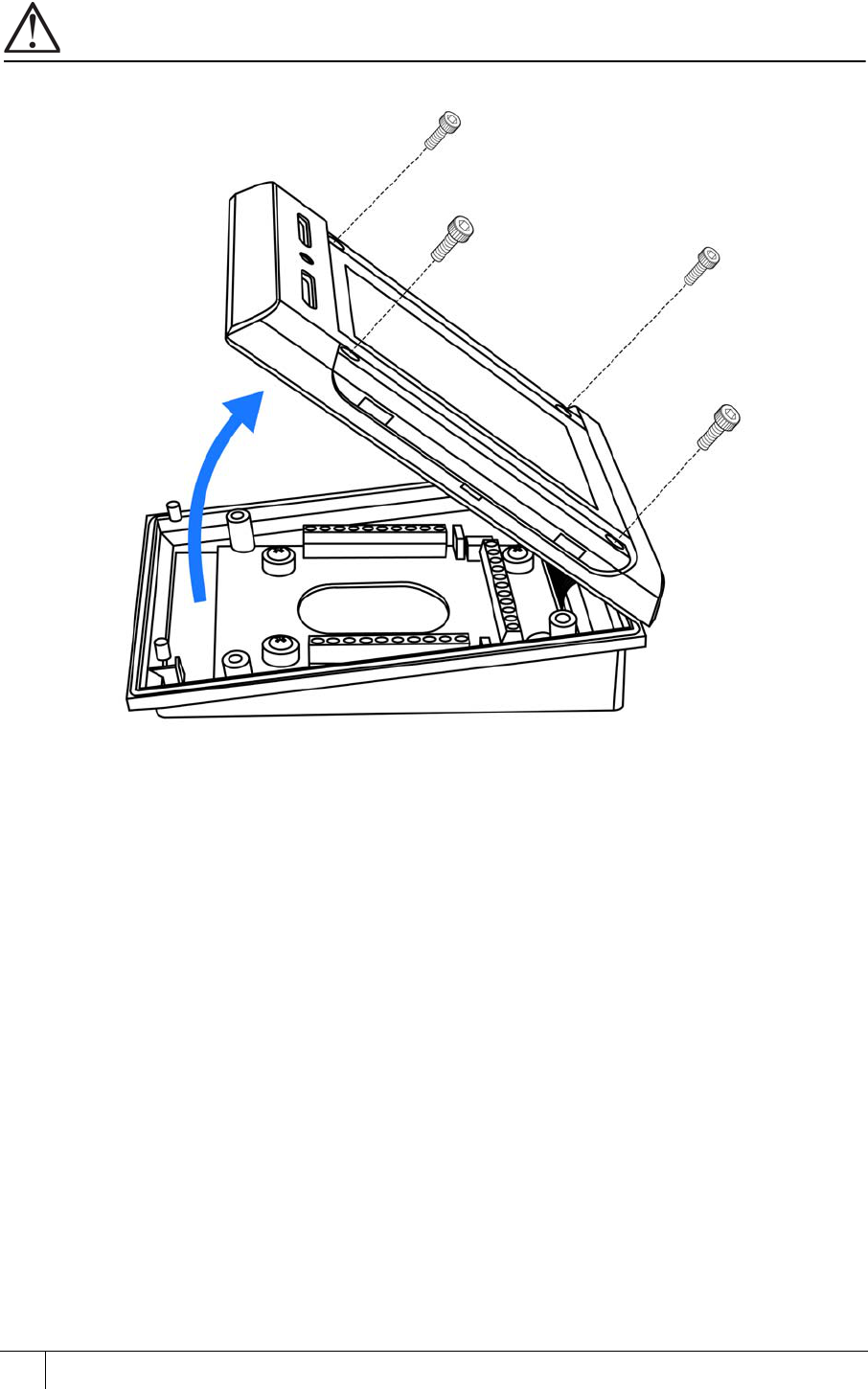
2.1.2 Opening the terminal
Important
Take care not to strain the ribbon cable connecting the two halves of the terminal.
Figure 6 Opening the terminal
1. Set the terminal on a stable, level surface to reduce the risk of the front of the terminal
falling when it is disconnected.
2. Remove the four screws using a security hex screwdriver.
3. Carefully lift the top casing away from the back of the terminal, pivoting as shown.
4. Disconnect the ribbon cable from the I/O board before commencing wiring.
emerald TS100/200/300 Installation Manual
11
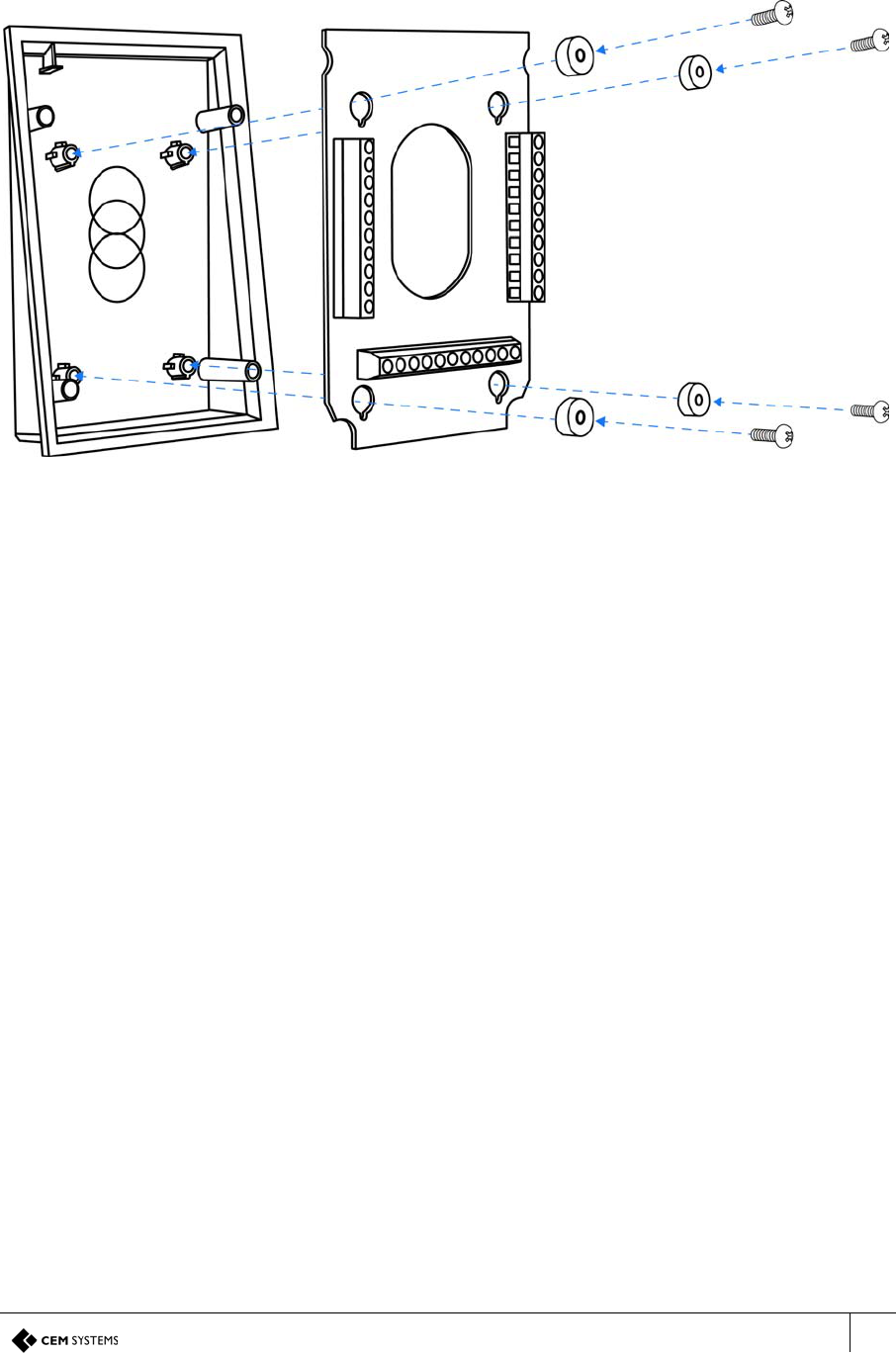
2.1.3 Mounting the terminal back casing
To access the mounting screw positions of the terminal the Input/Output board must first be
removed from the back box.
Figure 7 Exploded view illustration of the back casing and I/O board
1. Remove the four screws and spacers using a star head screwdriver.
2. Lift the I/O board away from the mountings.
3. Drill the back outer casing as required for cable access and back box mounting. (see
Figure 8)
4. Fit the back casing to the back box.
5. Re-attach the input/output PCB to the back casing ensuring to replace the spacers.
A - Back casing
B - I/O board
C - Spacers
D - Mounting screws
C
C
D
D
D
D
AC
B
C
TSR-IM-0045-1.6
CHAPTER 2 : Mounting the Terminal
12
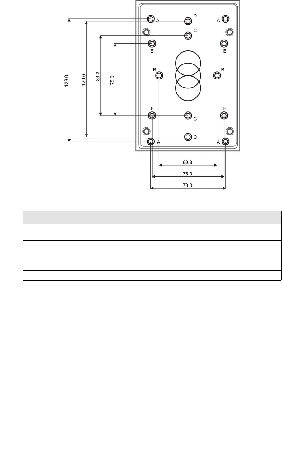
Drilling the back casing
Figure 8 emerald back casing drill hole dimensions
Mounting hole Description
AGeneric positions for wall mounting. These holes are accessible when
the I/O board is in place.
BUK single back box.
CUS Single back box.
DUK double back box mounted vertically.
E75mm VESA mount.
Table 5: emerald mounting descriptions

13
Chapter 3
Wiring the Terminal
3.1 Cabling requirements
Table 6 on page 13 outlines recommended cabling requirements for each of the connectors on
the emerald terminal.
3.1.1 Ethernet host
Ethernet communications should be cabled & terminated for 100Base-T operation according
to IN ANSI/TIA/EIA-568-A / TIA/EIA-568-B.
Due to limited space, additional care should be taken when using CAT6 connectors or CAT5
connectors with a strain relief boot at the terminal. There should be enough spare cable left
within the enclosure/back box to allow a service engineer to open the terminal case without
straining the RJ45 connector. Where the cable is subject to movement or vibration, stranded
ethernet cable (and appropriate connectors) should be used.
Purpose Recommended Cable Connector
Power over Ethernet & ethernet
comms Cat 5/5e/6 RJ45
12V power supplied separately Recommend using a CEM Door
Interface Unit 210/230 14AWG Screw
Terminal
Inputs Belden 95XX or equivalent (XX =
the number of pairs from 01 - 50) 14AWG Screw
Terminal
Outputs Belden 9462 or equivalent 14AWG Screw
Terminal
Connection with exit reader or
DIU Belden 8723 (AWG22 shielded
twisted 2-pair) or equivalent 14AWG Screw
Terminal
Wiegand Belden 9514 (7 x 22AWG), Alpha
1229C(9 x 22AWG) or equivalent 14AWG Screw
Terminal
Table 6: Terminal installation cabling requirements
Type Cable Connector Location
Host CAT5/CAT5e/CAT6 (PoE) RJ45 Socket Terminal board
Table 7: Ethernet host
A2SE67-UG-0011-1
CHAPTER 3 : Wiring the Terminal
14
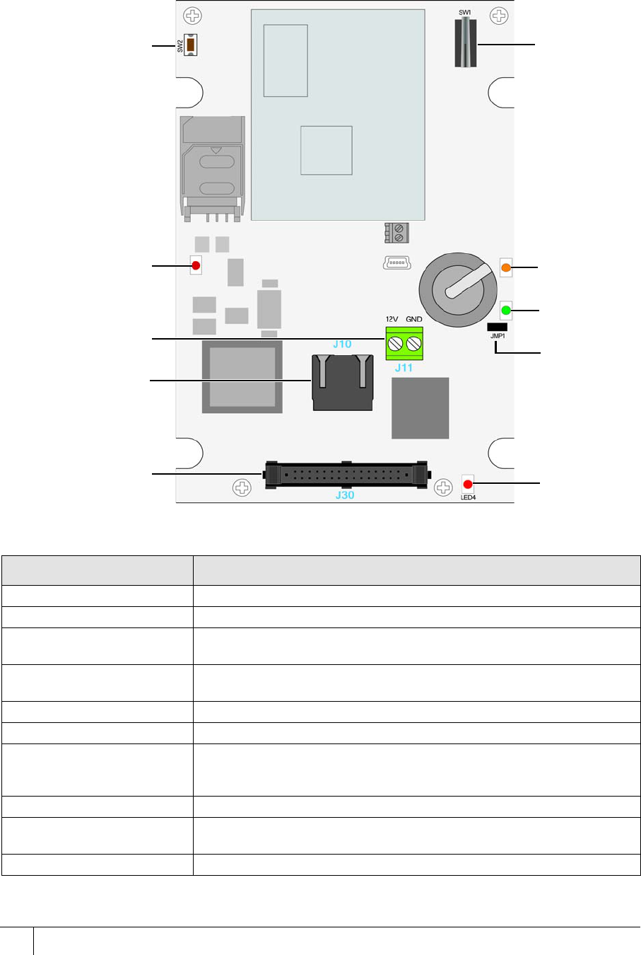
3.2 The Front Board
The front PCB contains the main electronic components of the reader; it is also where ethernet
communications must be connected.
Figure 9 Illustration of the front board
A. Reset button J. Tamper
switch
B. PoE Indicator
LED
I. Network
link speed
LED
H. Ethernet
activity LED
G. Battery
backed clock
link
C. Optional
DC12V
E. Ribbon
connector to
the I/O board F. 12V power
LED
D. RJ45
Component Description
A. Reset button Used to hard reboot the terminal.
B. PoE Indicator LED Green indicates that the terminal is using PoE.
C. Optional DC12V 12V power can be supplied to the terminal using this connector, however it is
recommended that power be supplied via the I/O board.
D. RJ45 connector Used to ethernet communications and also for Power over Ethernet when
being used.
E. Ribbon connector Links the front PCB to the I/O PCB.
F. 12V power LED Red indicates DC12V power is being supplied to the board
G. Battery backed clock link This link is fitted at the factory. If the link is removed the reader will not store
the current time & date; card transactions may fail die to a mismatch in
time/date.
H. Ethernet activity LED Flashing green indicates ethernet activity
I. Network link LED Orange indicates 100baseT connection speed. Unlit indicates 10baseT
connection speed.
J Tamper switch Used to trigger an alarm when the case is opened.
Table 8: Description of front board components
AC2000 Getting Started Guide
15
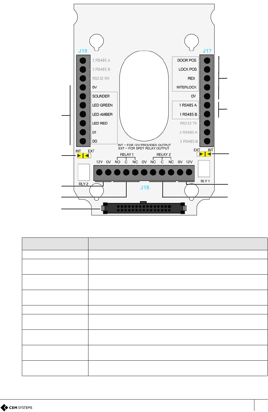
3.3 The Input/Output Board
The input/output board provides connections points for terminal power, inputs, outputs,3rd
party Wiegand read heads, communications with exit readers and door interface units.
Figure 10 Illustration of the Input/Output board
Component Description
A. Wiegand interface Interface for third party exit heads using Wiegand protocol.
B. Output 0 switch Switches output 0 between internal 12V provided and voltage not
provided relay that uses external power.
C. DC12V 12V power, either from a CEM Door Interface Unit or an appropriate
power source is supplied via this connector.
D. Output 0 Lock output, either 12V provided by the terminal or 12/24V provided
externally via the relay.
E. Ribbon connector Links the I/O PCB to the front PCB.
F. Output 1 Spare output. The output is also used when configuring the reader in
interlock mode.
G. Output 1 switch Switches output 1 between internal 12V provided and voltage not
provided relay that uses external power.
H. Comms to exit/DIU Serial communications to a CEM exit reader such as the S610s or a Door
Interface Unit
I. Input connectors Connection points for monitored inputs such as door position, lock sense
and request to exit switches.
Table 9: Description of I/O board components
H. Comms to
exit/DIU
G. Output 1
state switch
B. Output 0
state switch
A. Wiegand
read head
interface
D. Output 0
(lock)
F. Output 1
(spare)
E. Ribbon
connector
I. Input
connectors
C. DC12V C. DC12V
A2SE67-UG-0011-1
CHAPTER 3 : Wiring the Terminal
16
3.4 Wiring locks
The terminal supports lock types rated 12-24V at 1.5A max current if using an external power
supply. It is recommended that the lock is powered by an external power supply as this
provides the most flexibility. However if required, internal power to a lock can be provided at
12V, 650mA max current.
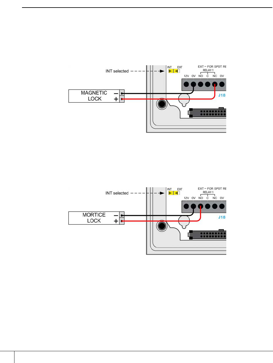
3.4.1 Wiring a voltage provided lock (internal power)
Only12V locks can be wired to be powered internally by the terminal. When internal power is
utilised it is possible to connect locks in a fail safe or fail secure configuration.
Note
The maximum current that can be supplied is 1.5A using an external power supply or 650mA
from the internal supply.
Fail safe lock
The fail safe configuration means that in the event of a power loss to the terminal the lock will
open allowing free access. A lock that is constantly powered such as a maglock must be used.
Figure 11 Illustration of wiring for a fail safe lock
Fail secure lock
The fail secure configuration means that in the event of a power loss to the terminal the lock
will remain secure. A lock that requires power to open such as a shear lock must be used.
Figure 12 Illustration of wiring for a fail secure lock
AC2000 Getting Started Guide
17
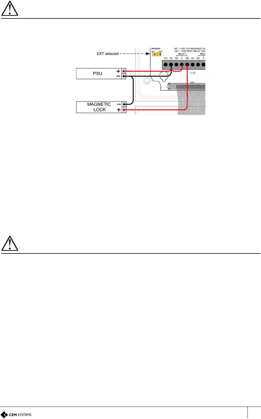
3.4.2 Wiring a voltage not provided lock (external power)
Important
When using 24V power for a lock, it is imperative that the switch position is set to EXT. Setting the switch to INT
will result in 24V being supplied to the terminal which may cause irreversible damage.
This is the recommended wiring configuration when locks require 24V or more than 650mA.
Figure 13 Illustration of wiring for lock with external power provided
3.4.3 Output power switch
Each of the two outputs has a switch that allows power to be provided to the output from the
terminal’s internal power circuit or by an external power source.
External power
When the switch is set to EXT a separate DC12 - 24V power source must be used to provide
power for any locks or other devices such as sounders attached to the output.
Internal power
When the switch is set to INT, DC12V 650mA max current in total is provided to the lock or
other devices attached to the outputs from the terminal’s internal power circuitry.
Important
The terminal’s 12V connectors all link to the same circuit, powering the terminal and any outputs set to INT. It is
imperative that before attaching 24V to power an output checks should be made that the relevant output switch is
set to EXT. Applying 24V to an output with the switch set to INT will result in 24V being supplied to the common
power circuitry, potentially damaging the terminal.
3.4.4 Inputs not in use
Some inputs must be linked out when not in use, to prevent alarms being generated on the
system. These are:
• Input 0 - door position sensor
• Fire input on a Door Interface Unit
• Tamper input on a Door Interface Unit
• Break Glass input on a Door Interface Unit
A2SE67-UG-0011-1
CHAPTER 3 : Wiring the Terminal
18
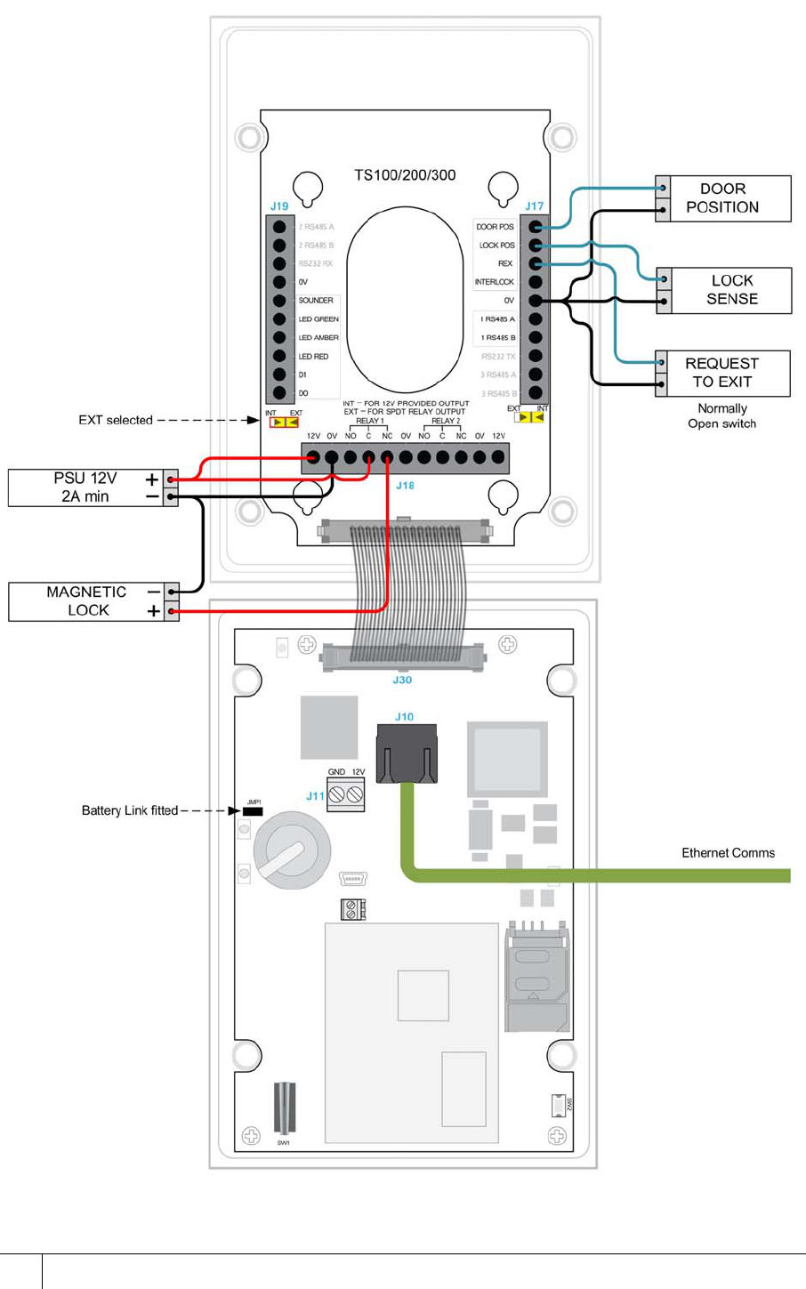
3.5 Terminal with Request to Exit Switch
Figure 14 emerald master terminal with REX wiring diagram

AC2000 Getting Started Guide
19
3.6 Configuration information
Wiring an emerald terminal with a request to exit switch is the most basic wiring configuration
and is not recommended for use on high security doors.
Input configuration
The table below illustrates the configuration and operation of the inputs on the terminal when
configured with a Request to Exit switch.
Note
Wiring diagram is for the installation of the emerald terminal in Door Mode.
Input number Input function Default input trigger state change
0 Door position short => open
1 Lock position short => open
2 Request to exit switch open => momentary short => open
3 Spare/Interlock short => open
Table 10: emerald and request to exit switch input configuration
A2SE67-UG-0011-1
CHAPTER 3 : Wiring the Terminal
20
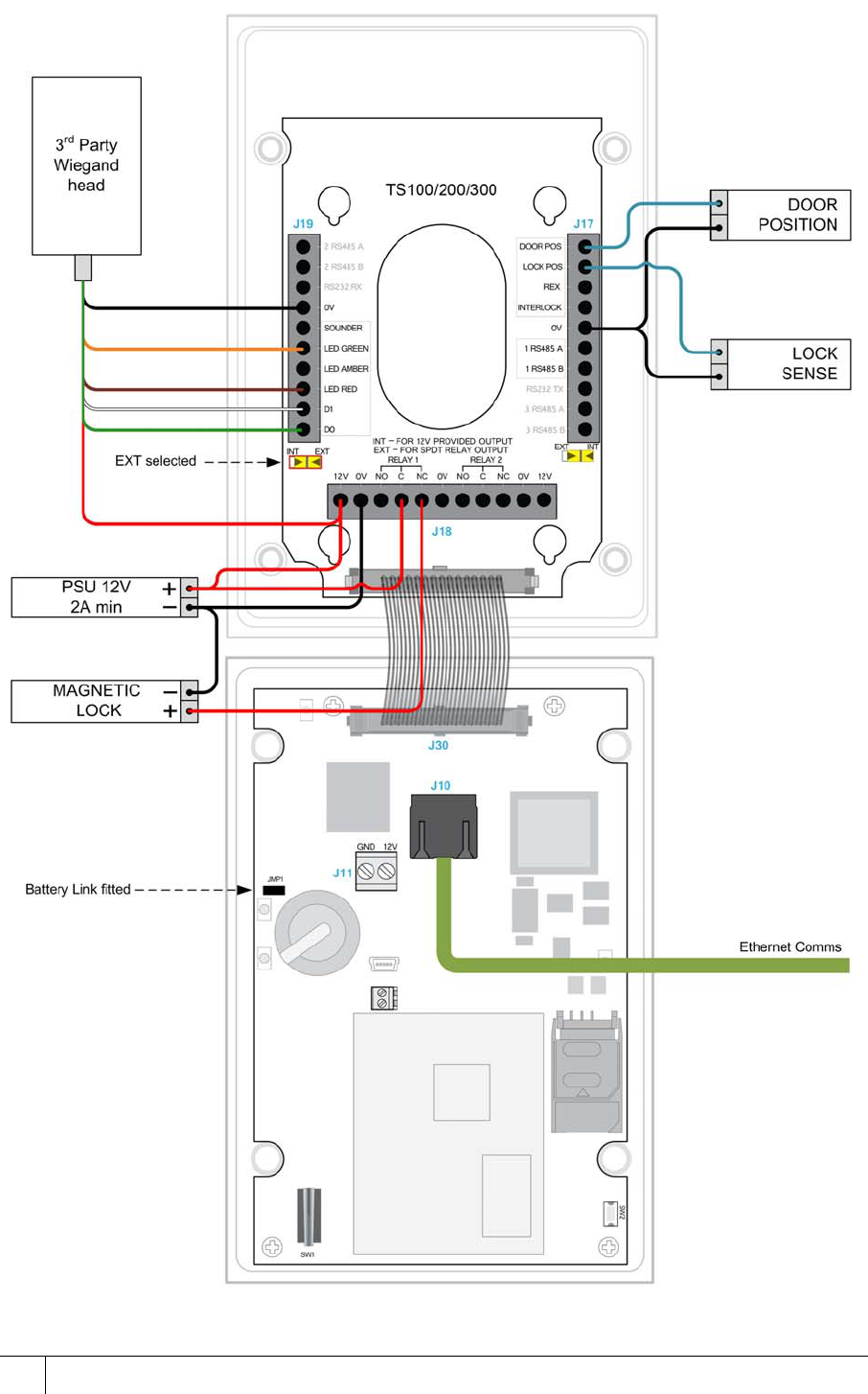
3.7 Terminal with 3rd Party Wiegand Read Head
Figure 15 emerald master terminal with Wiegand read head wiring
AC2000 Getting Started Guide
21
3.8 Configuration information
The emerald terminal facilitates the use of a third party exit Wiegand head with three LEDs.
Supported third party read heads
CEM support the use of HID R10 heads for reading Mifare and iClass cards.
Note
The sounder functionality of third party read heads is not supported.
Typical Wiegand read head wiring
For specific read head wiring consult the third party manufacturer.
Important
For proper regulatory compliance, the drain wire should be disconnected at the power supplied end of the cable.
Input configuration
The table below illustrates the configuration and operation of the inputs on the terminal when
configured with a third party Wiegand read head.
Note
To configure a Slave reader as the Master reader, refer to the Appendix on page 85.
Product CEM Product Code
HID iClass SE R10 SmartCard Reader HDS/053/010
HID iClass SE R30 SmartCard Reader HDS/053/030
HID iClass SE R40 SmartCard Reader HDS/053/040
Table 11: Read head product code
I/O board connection Typical HID colour
GND Black
Sounder Not Supported
Green LED Orange
Amber LED Not fitted
Red LED Brown
Data 1 White
Data 0 Green
Head 12V Red
Table 12: Typical Wiegand head wiring
Input number Input function Default input trigger state change
0 Door position short => open
1 Lock position short => open
2 Request to exit switch open => momentary short => open
3 Spare / Interlock short => open
Table 13: emerald and 3rd party read head input configuration
A2SE67-UG-0011-1
CHAPTER 3 : Wiring the Terminal
22
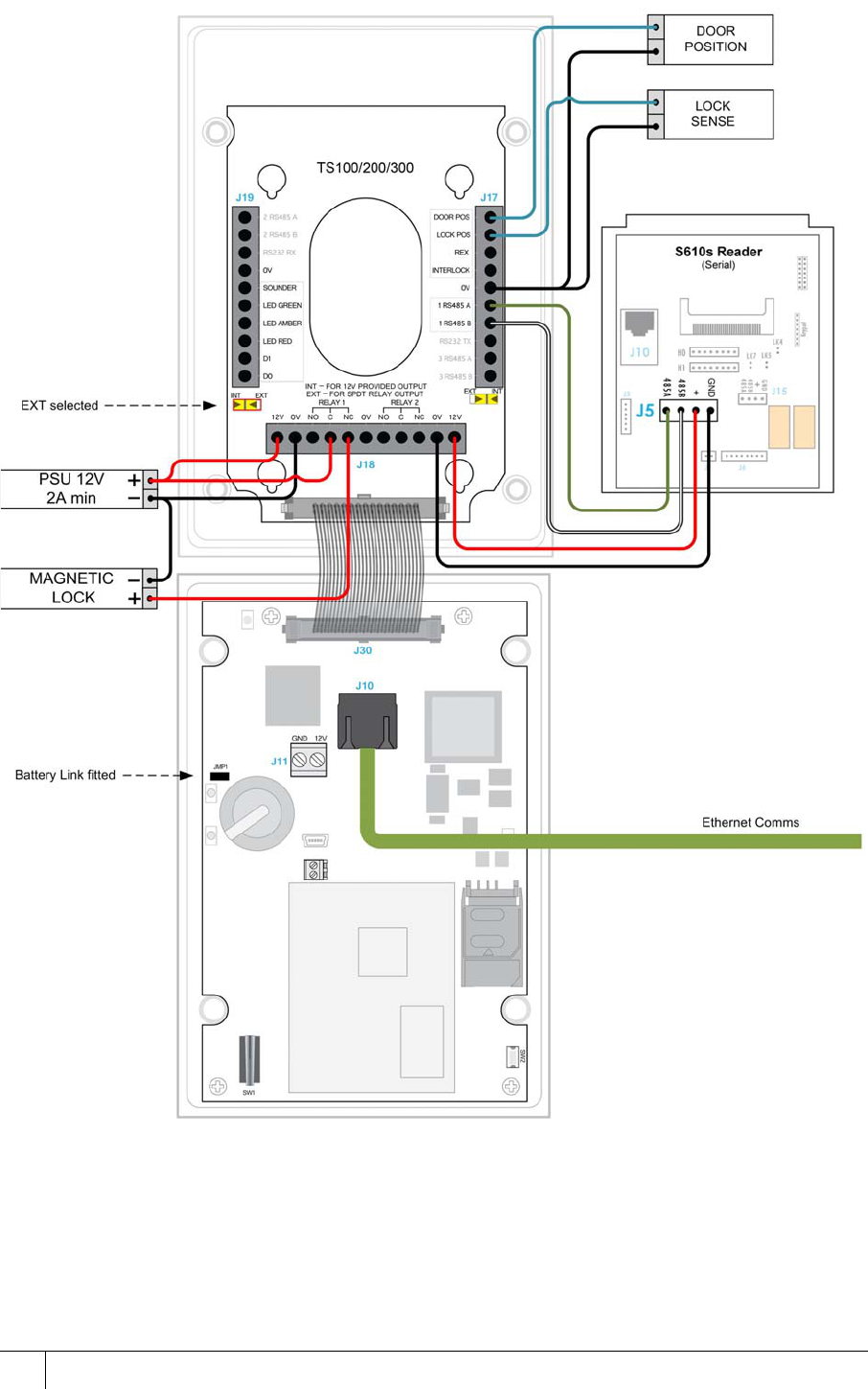
3.9 Terminal with S610s Exit Reader
Figure 16 emerald master terminal with S610s exit reader

AC2000 Getting Started Guide
23
3.9.1 Configuration information
Using a CEM S610s exit reader provides a higher level of security at the door than using a
third party read head.
Input configuration
The S610s reader has four inputs and two relay outputs which are spare in this configuration.
Product CEM Product Code
S610s Card Reader (Mifare CSN) RDR/612/105
S610s Card Reader (DESfire) RDR/612/107
S610s Card Reader (iClass) RDR/612/108
S610s Card Reader (Pico Pass) RDR/612/106
Table 14: S610s product code
Input
number Input
location Input function Default input trigger state change
0Master
terminal Door position short => open
1Master
terminal Lock position short => open
2Master
terminal Request to exit switch open => momentary short => open
3Master
terminal Spare / Interlock short => open
4 S610s exit Spare normally open
5 S610s exit Spare normally open
6 S610s exit Spare normally open
7 S610s exit Spare normally open
Table 15: emerald and S610s exit reader input configuration
A2SE67-UG-0011-1
CHAPTER 3 : Wiring the Terminal
24
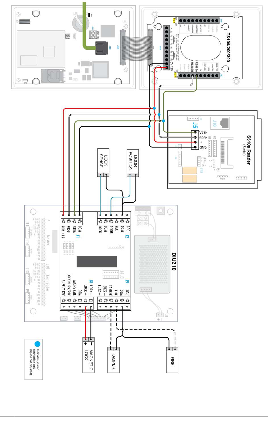
3.10 Terminal with DIU 210
Figure 17 emerald master terminal with a DIU 210 wiring
AC2000 Getting Started Guide
25
3.10.1 Configuration information
Using a CEM DIU210 provides the highest level of security at a door, removing power for the
lock and input monitoring away from the door reader.
Important
The DIU210 uses mains electricity and should only be installed by qualified personnel.
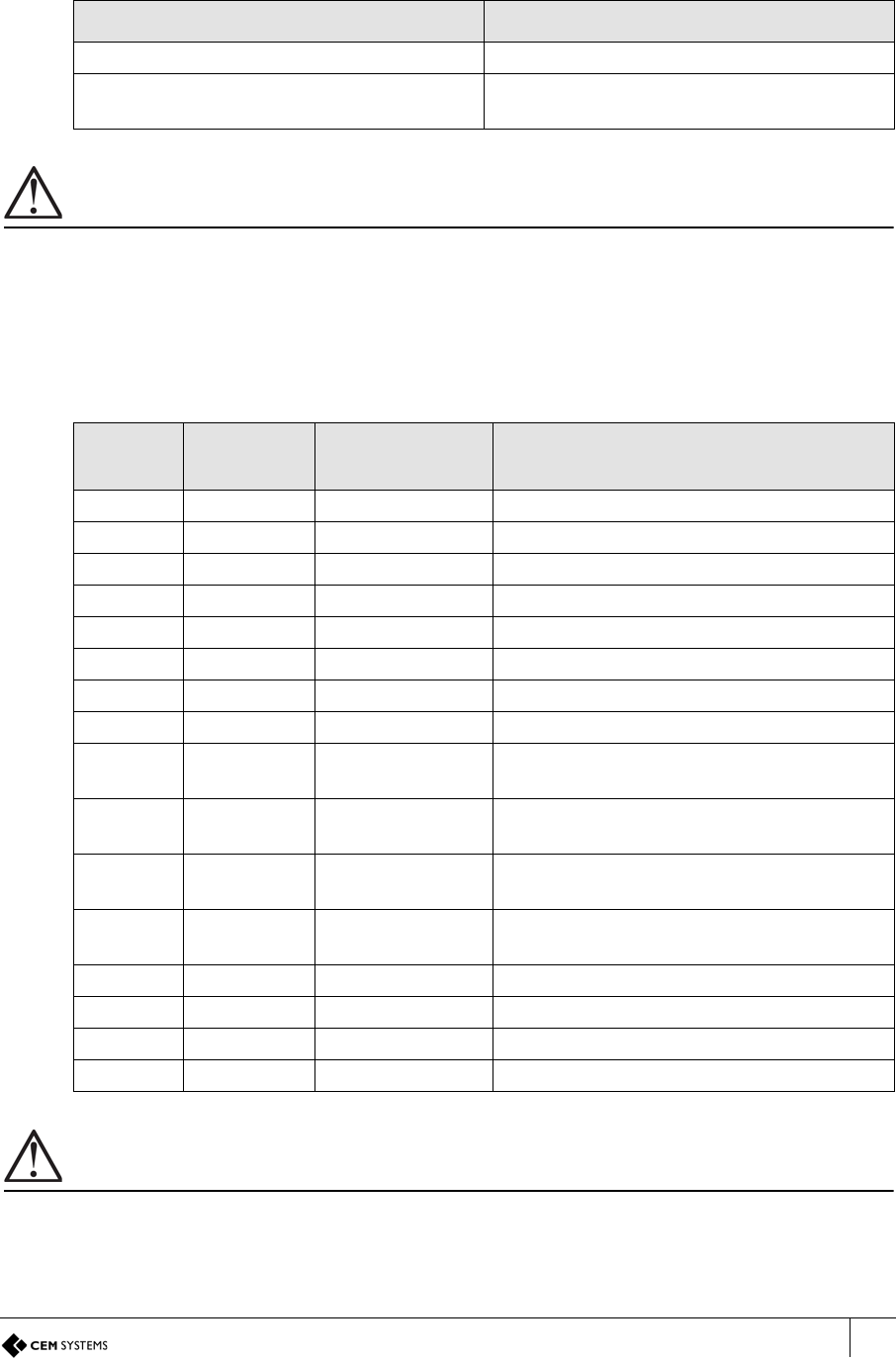
Input configuration
When a DIU210 is used with a terminal, the DIU controls the main CEM reserved inputs and
the inputs on the readers become spare. The exception to this is input three on the terminal
(input B in Table 6 on page 13) which maintains its status as being used for interlock mode.
Important
If a decision has been made not to connect a fire and break glass units to the DIU the inputs must be linked out to
ensure that the DIU functions normally. The tamper input must also be linked out when not in use to prevent
alarms being generated on AC2000.
Product CEM Product Code
DIU 200 (Compact board only DIU module) DIU/700/200
DIU 210 Full DIU incl Enclosure/PSU (Does
not include backup batteries) DIU/700/210
Table 16: Door Interface Units product code
Input
number Input
location Input function Default input trigger state change
0 DIU Door position short => open
1 DIU Lock position short => open
2 DIU Request to exit switch open => momentary short => open
3 DIU Break glass short => open
4 DIU Fire short => open
5 DIU Mains power fail Internally triggered
6 DIU Battery low Internally triggered
7 DIU DIU tamper short => open
8Master
terminal Spare short => open
9Master
terminal Spare short => open
AMaster
terminal Spare short => open
BMaster
terminal Spare / Interlock short => open
C Exit reader Spare normally open
D Exit reader Spare normally open
E Exit reader Spare normally open
F Exit reader Spare normally open
Table 17: emerald and DIU210 input configuration
A2SE67-UG-0011-1
CHAPTER 3 : Wiring the Terminal
26
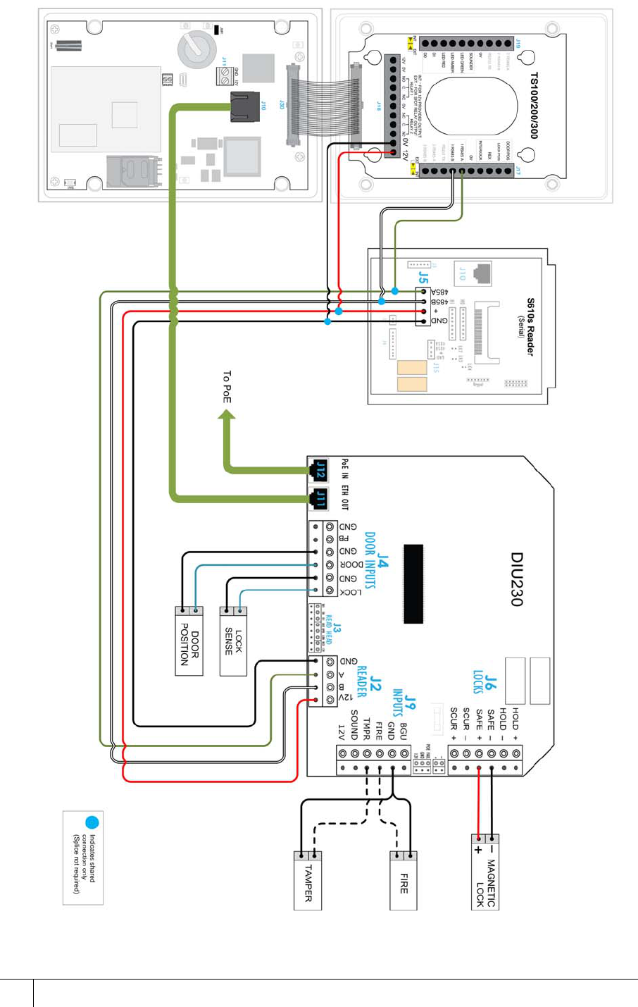
3.11 Terminal with DIU 230
Figure 18 emerald terminal with DIU 230 wiring

AC2000 Getting Started Guide
27
3.11.1 Configuration information
Using a CEM DIU230 provides the highest level of security at a door, removing power for the
lock and input monitoring away from the door reader. The DIU is a PoE+ device and does not
require specialist electrical qualifications to install.
Input configuration
When a DIU230 is used with a emerald terminal, the DIU controls the main CEM reserved
inputs and the inputs on the readers become spare. The exception to this is input three on the
emerald terminal (input B in the table below) which maintains its status as being used for
interlock mode..
Important
If a decision has been made not to connect a fire and break glass units to the DIU the inputs must be linked out to
ensure that the DIU functions normally. The tamper input must also be linked out when not in use to prevent
alarms being generated on AC2000.
Product CEM Product Code
DIU 230 PoE+ (board only) DIU/700/230
DIU 230 PoE+ (with enclosure) DIU/700/231
Table 18: DIU230 product codes
Input
number Input
location Input function Default input trigger state change
0 DIU Door position short => open
1 DIU Lock position short => open
2 DIU Request to exit switch open => momentary short => open
3 DIU Fire short => open
4 DIU Breakglass short => open
5 DIU Mains power fail Internally triggered
6 DIU Battery low Internally triggered
7 DIU DIU tamper short => open
8Master
terminal Spare short => open
9Master
terminal Spare short => open
AMaster
terminal Spare short => open
BMaster
terminal Spare / Interlock short => open
C Exit reader Spare normally open
D Exit reader Spare normally open
E Exit reader Spare normally open
F Exit reader Spare normally open
Table 19: emerald and DIU230 input configuration
A2SE67-UG-0011-1
CHAPTER 3 : Wiring the Terminal
28
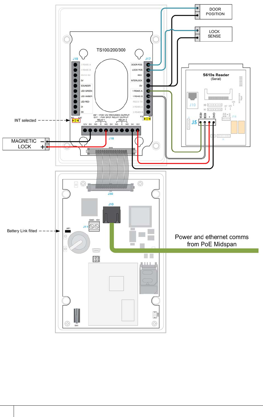
3.12 PoE+ Terminal with S610s Exit Reader
Figure 19 PoE emerald with S610s exit reader wiring
AC2000 Getting Started Guide
29
3.12.1 Configuration
Important
When powering the emerald terminal using PoE+, the total peak current draw of the attached door furniture must
not exceed 840mA.
Using a CEM S610s exit reader provides a higher level of security at the door than using a
third party read head.
Input configuration
The S610s reader has four inputs and two relay outputs which are spare in this configuration.
Product CEM Product Code
S610s Card Reader (Mifare CSN) RDR/612/105
S610s Card Reader (DESfire) RDR/612/107
S610s Card Reader (iClass) RDR/612/108
S610s Card Reader (Pico Pass) RDR/612/106
Table 20: S610s product code
Input
number Input
location Input function Default input trigger state change
0Master
terminal Door position short => open
1Master
terminal Lock position short => open
2Master
terminal Request to exit switch open => momentary short => open
3Master
terminal Spare / Interlock short => open
4 S610s exit Spare normally open
5 S610s exit Spare normally open
6 S610s exit Spare normally open
7 S610s exit Spare normally open
Table 21: emerald and S610s exit reader input configuration
A2SE67-UG-0011-1
CHAPTER 3 : Wiring the Terminal
30
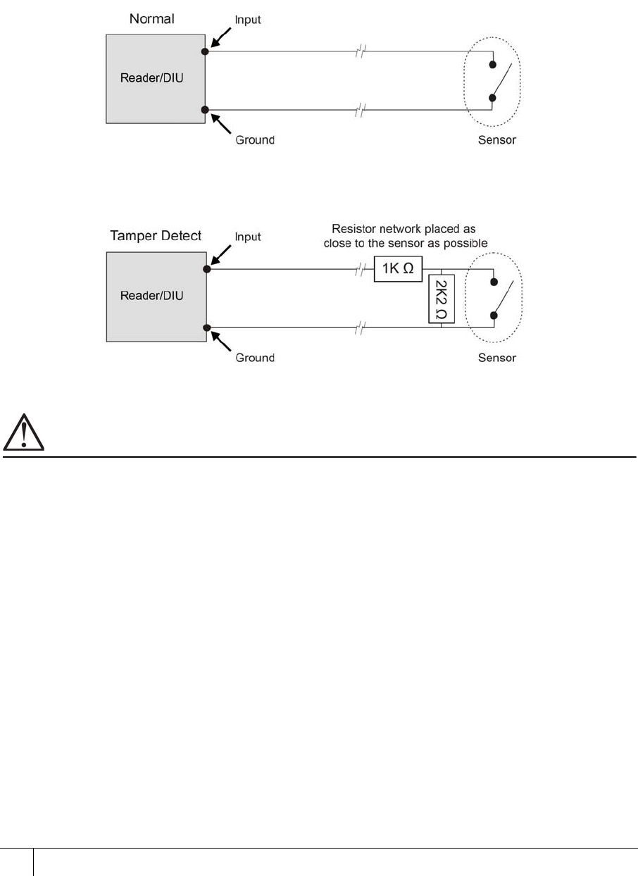
3.13 Tamper Detection on Reader Inputs
Terminal inputs can be monitored for four state tampering, open, close, tamper short and
tamper cut. If an input is tampered with an alarm will be triggered in the AC2000 software. The
alarm is a universal tamper alarm and does not distinguish between the four different states. In
order to monitor inputs for tamper short and tamper cut, a resistor network must be installed on
the input sensor wiring and the AC2000 software configured to monitor the input.
3.13.1 Wiring the resistor network
Figure 20 Illustration of the resistor network for four state tamper detection on inputs
Important
It is imperative that the tamper resistor network is wired as close to the sensor as possible.
3.13.2 Configuring software for tamper detection
1. From the Floatbar select Device Configuration | Devices.
2. Select the device on which inputs are to be configured for four state tamper detection.
3. Select the Configuration tab.
4. Select the Input Config tab.
5. Select each input element to be configured for four state and tick the 4 state checkbox.
6. Click Save.

AC2000 Getting Started Guide
31
3.13.3 Re-assembling the terminal
1. Ensure that there is adequate cable length available to reach the connectors comfortably
for each of the following:
–12vDC
– Cat5e/6 cable for communications and / or PoE
– Output wiring for lock
– Wiring for inputs e.g. door position sensor, lock sense
Important
To maintain the terminal’s IP65 rating, the cable access hole should be adequately sealed before completing the
installation process.
2. Attach the front pane of the terminal via the ribbon connector.
3. Attach the front of the terminal to the back casing and fix in places with the screws.
4. Attach the protective side panels to the terminal.
Note
If the terminal needs to be open after installation, the side panels can be removed by inserting
a 5 mm flat head screwdriver into the slot under the centre of the panel and sliding along the
length of the panel.

A2SE67-UG-0011-1
32
This page is intentionally blank.
33
Chapter 4
Reader Network Configuration
The network settings are accessed via the installer configuration menu on the terminal.
4.1 Checking emerald’s Network Status
1. Tap the Reader Address. The network status indicator is displayed for eight seconds.
Figure 21 Checking the network status
Each section of the status indicator represents a different aspect of the network connectivity.
The presence or absence of a block indicates whether or not the connection is good.
Figure 22 The network status indicator
Network status indicator
The top block indicates that
the terminal has received its
onboard database of
cardholders/timezones etc. The centre block indicates
that the terminal has received
its configuration settings from
the CDC
The bottom block indicates
that the terminal is connected
with the RTC. The TCP/IP indicator shows
ethernet connectivity.
A2SE67-UG-0011-1
CHAPTER 4 : Reader Network Configuration
34
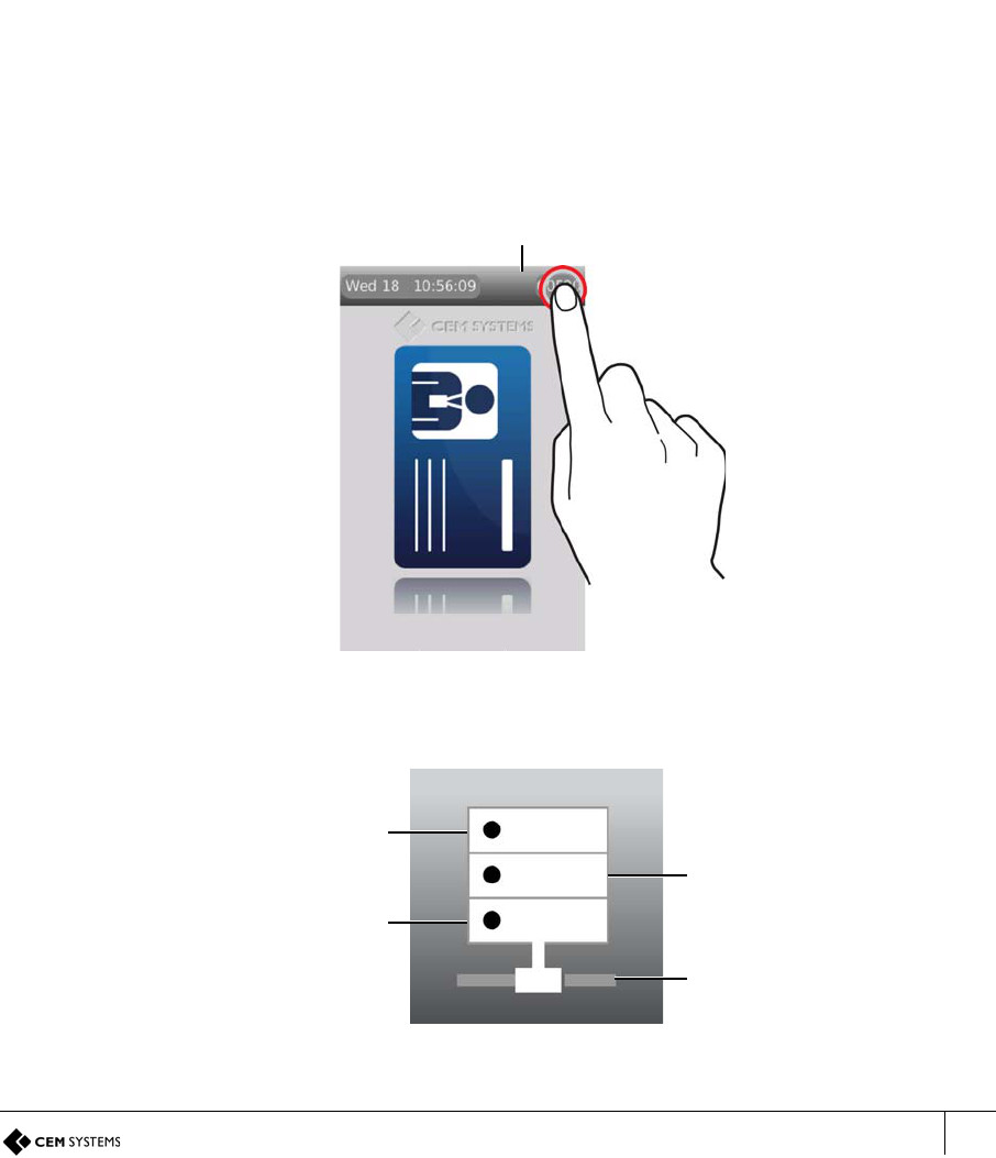
4.2 Accessing the Configuration Menu
1. Slowly swipe a finger across the date/time from left to right.
2. When prompted to enter passcode type 67679999.
Figure 23 Accessing the configuration menu
Note
Once the terminal has received a configuration from the server this passcode will be changed
to 67670000. The final four digits of this PIN are configurable for the terminal in the Devices
application, see section 6.3 Accessing the system configuration menu on page 48.
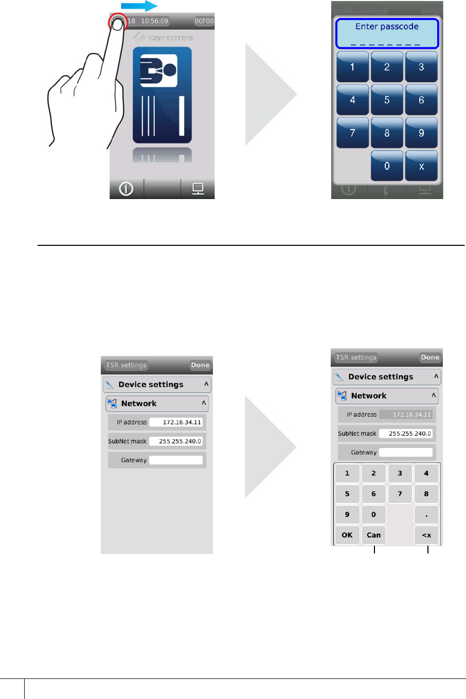
4.2.1 Setting the terminal IP address, gateway and subnet mask
1. From the Config Menu press Device settings | Network.
Figure 24 Configuring the terminal network settings
2. Press the IP address field, type the address and press OK.
3. Press the SubNet mask field, type address and press OK.
4. Press the Gateway field, type the address and press OK.
5. Press Done to close the Network menu.
Cancel Delete
AC2000 Getting Started Guide
35
4.2.2 Network routing - (advanced users)
The emerald terminal needs to be able to communicate with the Central Database Computer
(CDC) and the Real Time Computer (RTC). If a network is fragmented, and the reader, CDC
and RTC are on different parts of the network it may be necessary to route communications to
the RTC. In this situation contact the site network administrator.
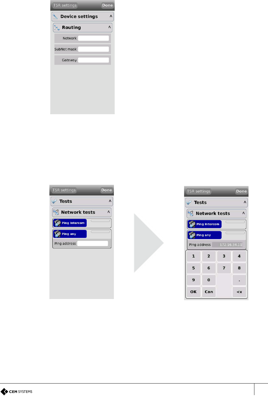
4.2.3 Testing the connection with the AC2000 server
The terminal can be used to test the connectivity with the AC2000 server via a PING utility.
1. From the Configuration Menu press Tests | Network tests
2. Press the Ping address field below Ping Other.
Figure 26 Testing the connection with the AC2000 server
3. Type the IP address of the AC2000 server (CDC/RTC) and press OK.
4. Press Ping Any.
i. If a response is received from the pinged address the Ping Any button will turn green.
ii. If no response is received from the address the Ping Any button will turn red.
5. The PING utility can be used to check connectivity to any device on the network.
Figure 25 The routing menu
1. From the Configuration Menu press
Device Settings | Routing.
2. Press the Network field, type the
network IP address and touch OK.
3. Press the SubNet mask field, type
address and touch OK.
4. Press the Gateway field, type the
address and press OK.
5. Touch Done to close the menu.

A2SE67-UG-0011-1
36
This page is intentionally blank.
37
Chapter 5
AC2000 Software Configuration
This section of the manual focuses on the initial addition and configuration of the device and input
alarms. All other advanced configuration options will be covered in the relevant function sections. The
emerald terminal is added to the AC2000 system and configured using the Devices application.
Note
This manual assumes access to the necessary AC2000 applications and should be performed
by person(s) trained in its use.
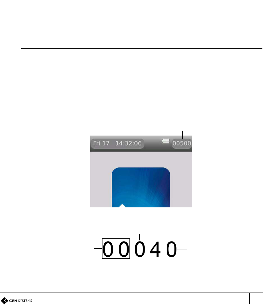
5.1 Reader Addressing
The AC2000 system communicates with all devices on the access control network using the
CEM reader addressing system.
All devices are allocated a five digit reader address, the address is displayed in the top right of
the terminal display.
Figure 27 Location of the reader address on the screen
Each digit of the reader address signifies a position on the Devices application hierarchy.
Figure 28 Illustration describing AC2000 reader addressing
Reader address
RTC number ranges
from 00 - DE
Device group number 0 - F
Device number 0 - F
Master / Exit
0 = Master reader
1 = Exit reader
A2SE67-UG-0011-1
CHAPTER 5 : AC2000 Software Configuration
38
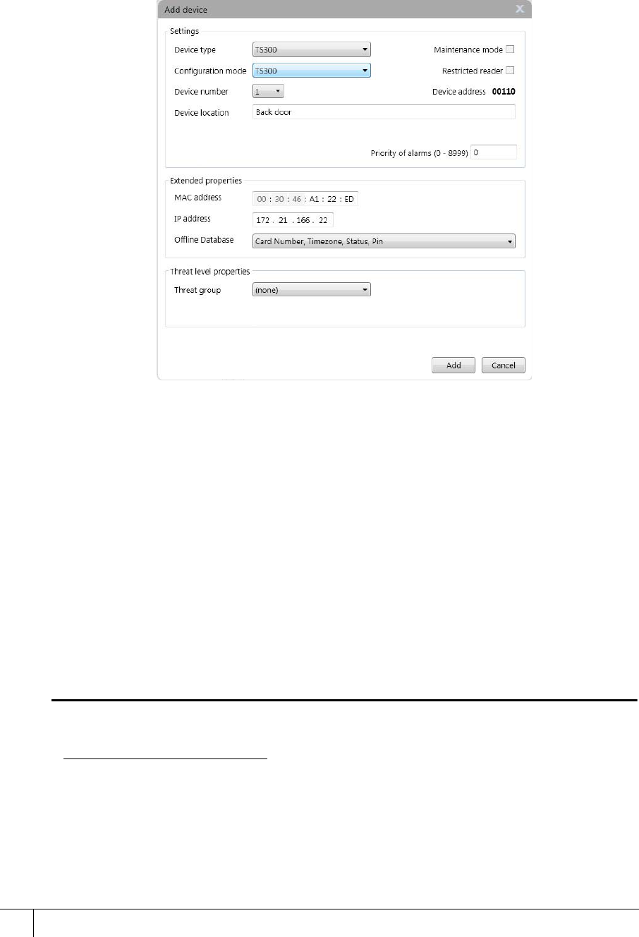
5.2 Adding the device to AC2000
1. From the AC2000 Floatbar open Device Configuration | Devices.
2. Select the controller and device group to which the device is to be added.
3. Right click the device group and select Add Device.
Figure 29 The add device dialogue with example terminal information
4. Select the Device Type TS100, TS200 or TS300 from the drop down menu.1
5. Select the Configuration Mode TS 100/200/300 from the dropdown list.2
6. Select a Device Number for the device.
7. Enter a unique Device Location description for the device
8. Where a slave device has been included in the Device Type, enter a unique Slave
Location description for the Slave device.
9. Enter the unique Mac Address of the device.
– This is found in the System information | Network on the emerald terminal.
10. Enter the unique IP address of the device.
11. Click Add. The terminal is now added to the AC2000 system.
Note
Threat groups are only used if threat levels have been activated on AC2000. For further
information consult the AC2000 Threat Levels manual.
1.If an exit or auxiliary device is added to the master reader, ensure to select the correct type, i.e. A
TS100 device with an Exit Reader would have a Device Type of TS100+Slave. This will configure
the Master device with an attached slave device.
Any exit reader added to a master will appear as a child node in the Overview Pane of the mas-
ter reader it is associated with.
2.The configuration mode contains default settings, however these can be user defined. To create a
configuration mode refer to the AC2000 User Guide.
AC2000 Getting Started Guide
39
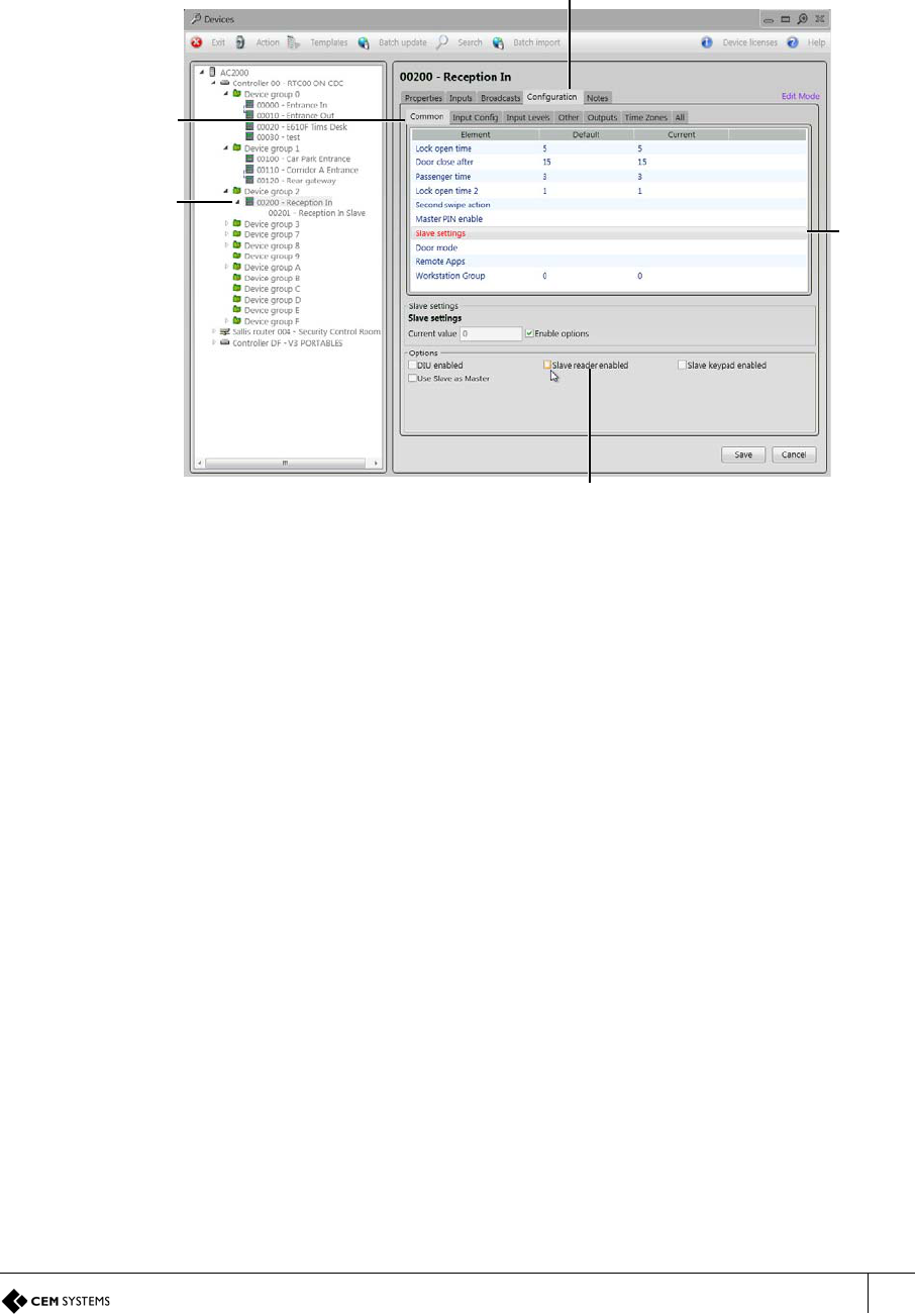
5.2.1 Configuring a 3rd party read head
After following the instructions in Adding the device to AC2000 on page 38, a Slave added to a
master reader is configured as slave reader by default. To configure the Slave to be a read
head only, perform the following steps:
1. From the AC2000 Floatbar, open Device Configuration | Devices.
Figure 30 3rd party read head configuration
2. Select the device (with associated slave) to be configured.
3. Select the Configuration tab.
4. Select the Common tab.
5. Select Slave Settings from the list in the main pane.
6. In the Options pane at the bottom of the interface, make sure that the Slave reader
enabled checkbox is not ticked.
7. Select Save.
The Slave associated with the master device is now configured as a 3rd party read head and
not a Slave reader.
Configuration tab
Common
tab
Slave reader enabled
Slave
settings
Selected
device and
associated
slave
A2SE67-UG-0011-1
CHAPTER 5 : AC2000 Software Configuration
40
5.3 Configuring Device Inputs
If inputs are to be used to trigger alarms or events in the AC2000 software they must be first be
configured in the Devices application.
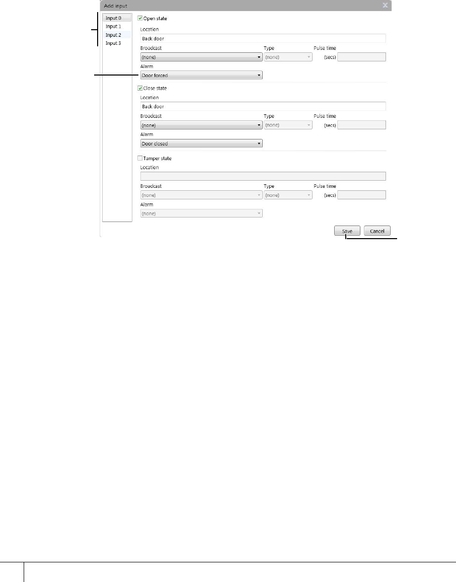
5.3.1 Adding an input alarm
1. From the AC2000 Floatbar select Device Configuration | Devices.
2. Select the device to configure from the overview pane.
3. Select the Inputs tab at the top of the main pane.
4. Click Add in the main pane.
Figure 31 Adding inputs dialog with example input 0 configuration
5. Select the Input from the list on the left which is to be configured.
6. Check the box next to the State name, this will enable the associated fields.
7. Select the Alarm which will be triggered on the change of state.
8. Click Save to save the Device Inputs configuration.
5.3.2 Configuring 4 state tamper inputs
1. Select the Configuration tab.
2. Select the Input Config tab.
3. Select each input element to be configured for four state and tick the 4 state checkbox.
4. Click Save.
Inputs
Alarm
type
Save
AC2000 Getting Started Guide
41
5.4 Editing emerald Entries in AC2000
The following instructions are only required if the settings need to be edited during or after
terminal installation.
5.4.1 Editing device properties
1. Select the master device in the overview pane.
2. Make the required changes and click Save.
5.4.2 Editing a device input
1. Select the Input and the Input State that is to be edited from the Device Inputs
2. Click Save when changes have been completed.
Note
Save is only displayed when a change has been made.
5.4.3 Deleting a device input
1. Select the input from the Device Inputs list.
2. Click Delete.
Note
Care should be taken when deleting an input as no warning message will appear.
5.4.4 Input alarms
The following section contains input tables describing the set-up for each of the emerald
configurations outlined in this manual, including the AC2000 alarms that should be selected for
each sensor state where appropriate:
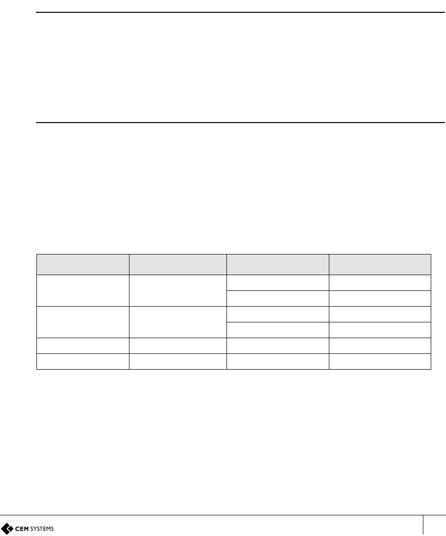
Input table for emerald with REX and emerald with third party read head:
Input number Input function Sensor state AED alarm
0 Door position Open Door forced
Closed Door closed
1 Lock position Open Lock not engaged
Closed Lock engaged
2 Request to exit No default
3 Spare / interlock No default
Table 22: emerald and REX / Third party read head input alarms

A2SE67-UG-0011-1
CHAPTER 5 : AC2000 Software Configuration
42
Input table for emerald with S610s exit reader:
Input table for emerald with DIU210 and S610s exit reader:
Input number Input function Sensor state AED alarm
0 Door position Open Door forced
Closed Door closed
1 Lock position Open Lock not engaged
Closed Lock engaged
2 Request to exit No default
3 Spare / interlock No default
4 Spare No default
5 Spare No default
6 Spare No default
7 Spare No default
Table 23: emerald and S610s exit reader input alarms
Input number Input function Sensor state AED alarm
0 Door position Open Door forced
Closed Door closed
1 Lock position Open Lock not engaged
Closed Lock engaged
2 Request to exit No default
3 Break glass Open Breakglass
Closed Breakglass reset
4 Fire Open Fire alarm
Closed Fire alarm reset
5 Mains power fail Open Mains power fail
Closed Mains OK
6 Battery low Open DIU battery low
7 DIU tamper switch Open DIU tamper
8 Spare No default
9 Spare No default
A Spare No default
B Spare / interlock No default
C Spare No default
D Spare No default
E Spare No default
F Spare No default
Table 24: emerald and DIU210 input alarms

AC2000 Getting Started Guide
43
Input table for emerald with DIU230 and S610s exit reader:
Input table for four state tamper configuration:
Input number Input function Sensor state AED alarm
0 Door position Open Door forced
Closed Door closed
1 Lock position Open Lock not engaged
Closed Lock engaged
2 Request to exit No default
3 Fire Open Fire alarm
Closed Fire alarm reset
4 Break glass Open Break glass
Closed Break glass reset
5 Mains power fail Open Mains power fail
Closed Mains OK
6 Battery low Open DIU battery low
7 DIU tamper switch Open DIU tamper
8 Spare No default
9 Spare No default
A Spare No default
B Spare / interlock No default
C Spare No default
D Spare No default
E Spare No default
F Spare No default
Table 25: emerald with DIU230 and S610s input alarms
Input number Input function Sensor state AED alarm
0 Door position Open Door forced
Closed Door closed
Tamper Input Tamper
1 Lock position Open Lock not engaged
Closed Lock engaged
Tamper Input Tamper
Table 26: Input table for four state tamper configuration
A2SE67-UG-0011-1
CHAPTER 5 : AC2000 Software Configuration
44
5.5 Assigning Remote Applications (TS300 model only)
To assign Remote Applications to users open AC2000 WEB by typing the IP address of the
AC2000 CDC into a browser and select System | Utilities | Remote Apps Allocation
Three steps must be taken in order to assign Remote Applications. First, a group or groups are
created by user type and then Remote Applications are added to the group. The final step is to
select the cardholder’s record in the AC2000 Personnel application and assign the Remote
Application Group to the user.
Note
For further information about setting up Remote Applications on the terminals consult the
AC2000 Web manual.
5.5.1 Creating groups
To create a Group of Remote Applications:
1. Select the Add Group button.
2. In the text box enter a Group Name and click the ADD button. (A Group Name could refer
to user types, e.g, Support, Managers, Engineers.)
If appropriate tick the Default Group check box to make the group the default setting in
the Personnel Application.
3. Press the Return button.
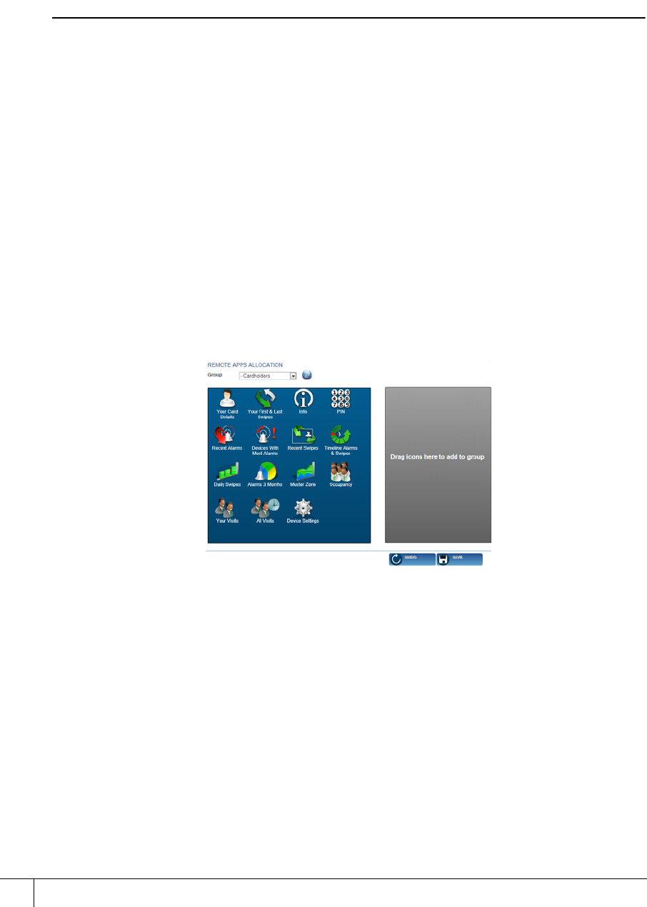
5.5.2 Adding remote applications to groups
To add Remote Applications to a group ensure the group name is selected in the Group drop
down list.
Figure 32 Adding Remote Applications to groups
1. Select a Remote Application or Applications by clicking on them in the blue pane (this
moves it to the grey pane, placing it in the selected Group).
2. Click Save.
AC2000 Getting Started Guide
45
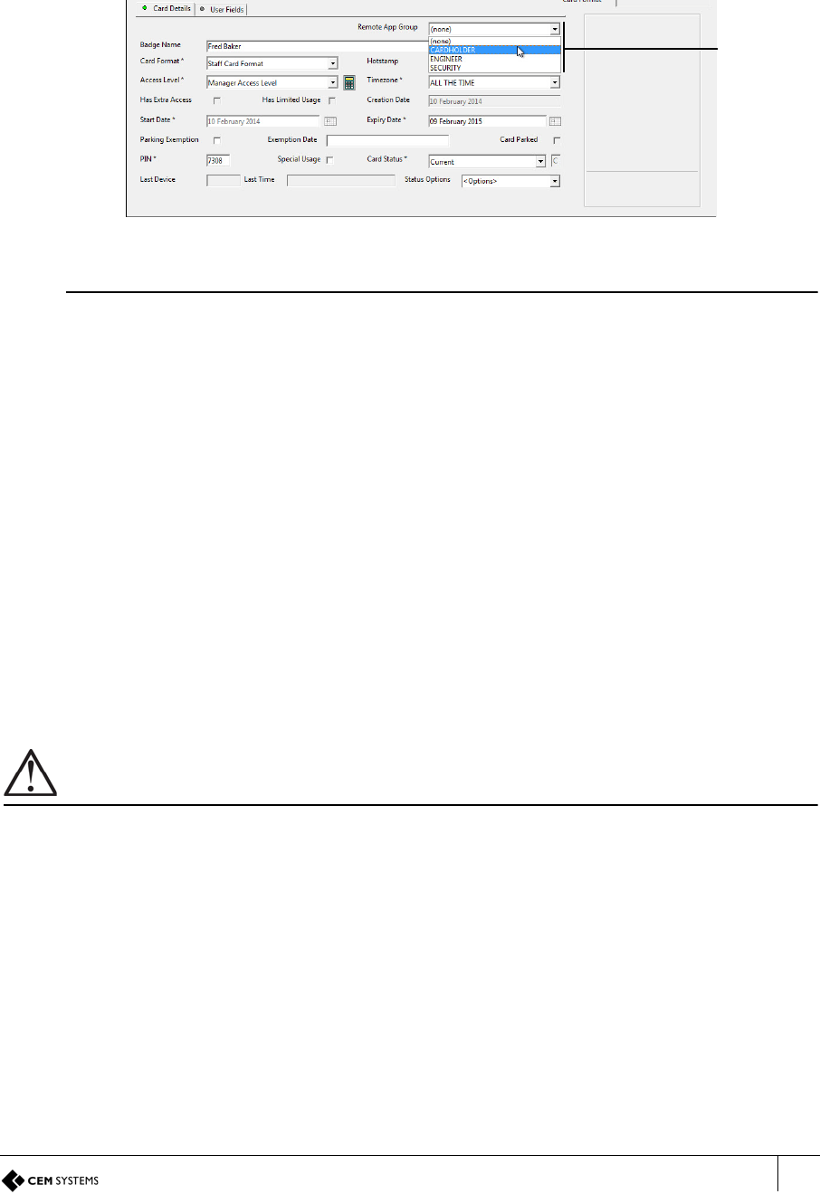
5.5.3 Assigning a remote application group to users
To assign a Remote Application Group to a cardholder:
1. Open AC2000SE | Enrolment | Personnel
2. Edit the cardholder’s record and select the appropriate listing from the Remote App.
Group drop down list.
Figure 33 Assigning Remote Application Group in Personnel
Note
If the Remote App Group drop down list is not visible in the Personnel interface, the option
has not yet been enabled. To enable this option, open the Configured application and scroll to
remote_app_group_enabled in the main pane. Type Y in the Value field and click Save. The
Remote App Group will now display as an option in Personnel records.
3. Click Save Changes button. The cardholder can now access the Remote Applications on
the terminal.
5.6 Next Steps
Congratulations! The emerald terminal is now fully installed. The remainder of the manual
details how to perform more advanced, complex tasks with the terminal including:
• Using the system configuration menu to view maintenance information and perform
terminal tests
• Configuring the terminal in additional modes such as passenger mode and control post.
• Upgrading terminal firmware
• Configuring device settings using the Device Settings Remote Application
Important
Advanced configuration of the terminal should only be carried out by users that have completed CEM AC2000
installer training.
Remote
App Group
drop down
list

A2SE67-UG-0011-1
46
This page is intentionally blank.
47
Chapter 6
The System Configuration Menu
emerald utilises an intuitive Graphical User Interface to access terminal functionality. At the basic level,
the screen is used to display meaningful messages regarding the current card swipe transaction. The
more advanced options allow the user to access information and reports that are relevant to them.
The emerald touch screen is a high quality capacitive screen, which is highly responsive in
multiple weather conditions. The reader interface provides access to a variety of tools, reports
and information such as:
• Terminal configuration options
• Diagnostics and tests
• Software and hardware versions
• User specific Remote Applications
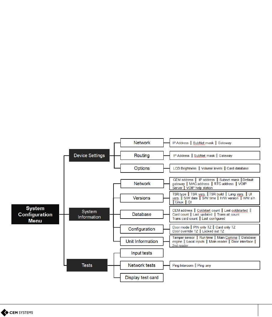
6.1 Menu Overview
Figure 34 Overview of the system configuration menu
TSR-IM-0045-1.6
CHAPTER 6 : The System Configuration Menu
48
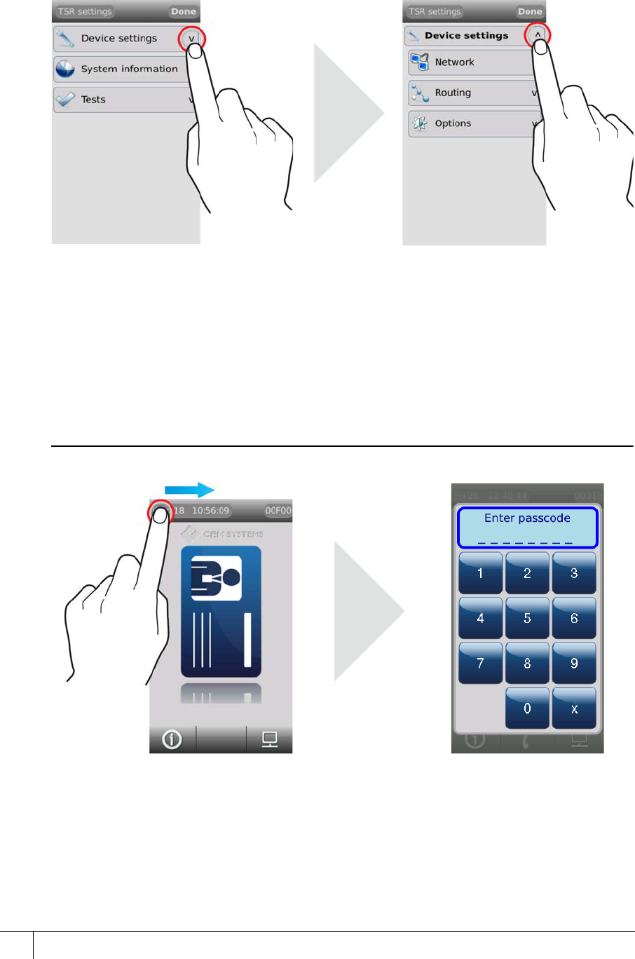
6.2 Navigation
Menus on the Touchscreen terminal are accessed by touching the menu option to expand.
• Menus are expanded and closed by pressing the menu name or the arrow.
Figure 35 Expanding and closing reader menus
6.3 Accessing the system configuration menu
To access the configuration menu:
1. Slowly swipe a finger across the date/time from left to right.
2. When prompted to enter passcode type 6767000.
Note
See Accessing the Configuration Menu on page 34 for more details on passcodes..
Figure 36 Accessing the configuration menu
Configuring the passcode
The final four digits of the passcode can be changed to a site or reader specific code.
1. Open the Device application and select the reader.
emerald TS100/200/300 Installation Manual
49
2. Select Configuration | Other | Diagnostic Pin.
3. Type the new PIN into the text field.
4. Click Save.
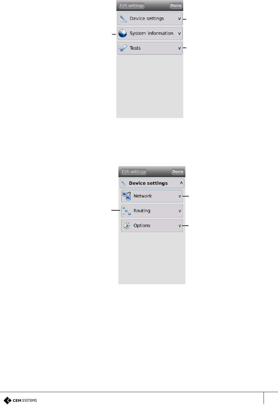
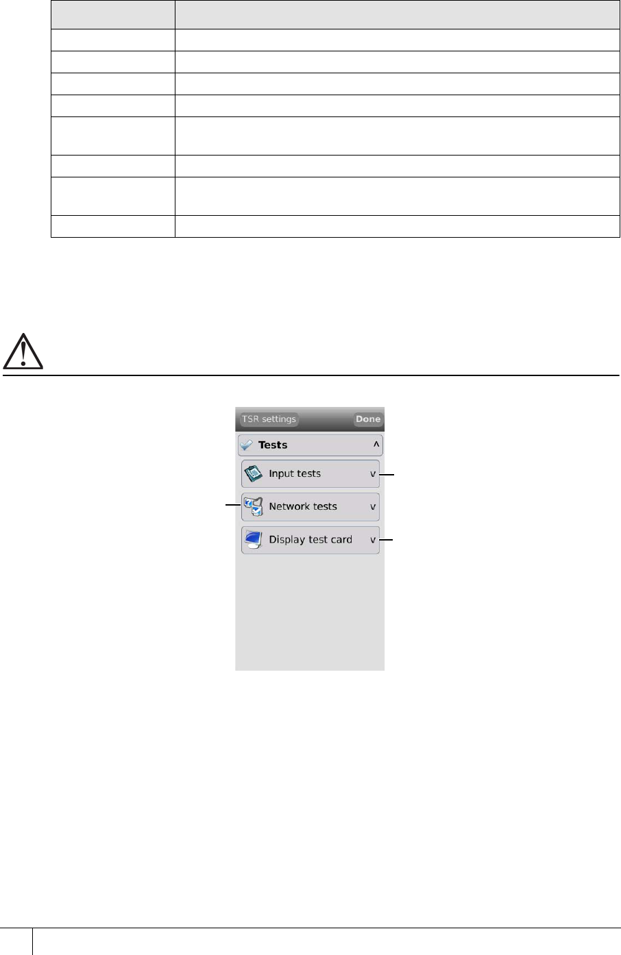
The system configuration menu has three sub-menus, each of which contains specific terminal
maintenance functions.
Figure 37 The system configuration menu
6.3.1 Device settings menu
The Device Settings menu is used to configure network and LCD settings.
Figure 38 The device settings menu
Configure terminal
settings
Access useful
information about the
terminal Administer tests to
check terminal
functionality
Configure terminal
network settings
Configure routing
settings in disjointed
networks Configure terminal
options
TSR-IM-0045-1.6
CHAPTER 6 : The System Configuration Menu
50
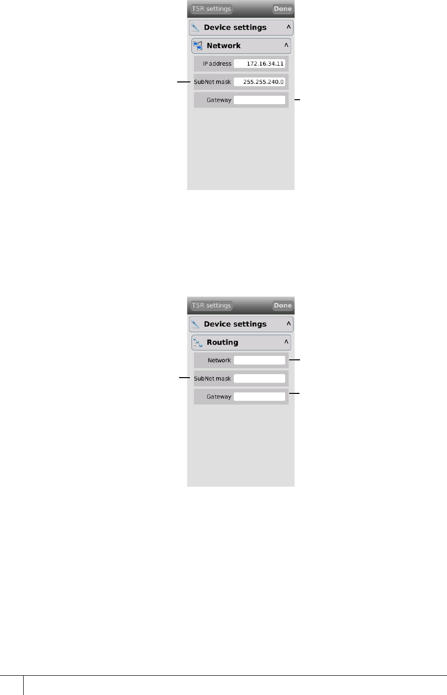
Network
The Network menu is used to configure the network settings for the terminal.
Figure 39 The Network menu
Routing
The emerald terminal needs to be able to communicate with the Central Database Computer
(CDC) and the Real Time Computer (RTC). If a network is fragmented and the reader, CDC
and RTC are on different parts of the network, it may be necessary to route communications to
the RTC. In this situation, contact the site network administrator.
Figure 40 The Routing menu
The IP address assigned to
the terminal
The SubNet mask of the
network that the terminal is
connected to The IP address of the
Gateway server where
appropriate
The IP address of the routing
network
The SubNet mask of the
routing network The IP address of the
gateway server
emerald TS100/200/300 Installation Manual
51
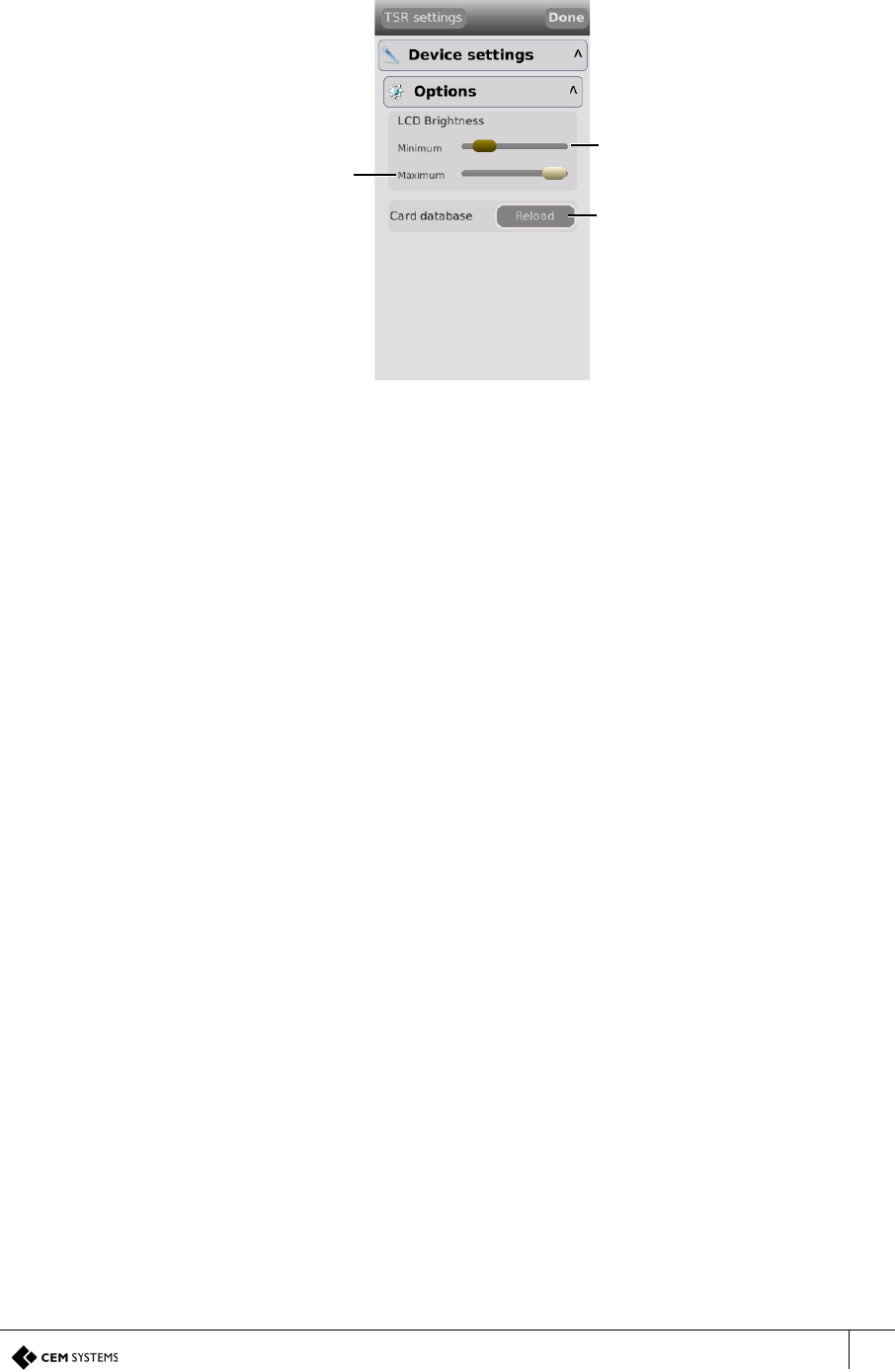
Options
The Options menu is used to change the LCD brightness and update the terminal’s onboard
cardholder database.
Figure 41 The Options menu
Use the slider to adjust the
minimum brightness of the
LCD (left is lowest)
Use the slider to adjust the
maximum brightness of the
LCD (left is lowest) Tap Reload to repopulate the
onboard database from the
CDC
TSR-IM-0045-1.6
CHAPTER 6 : The System Configuration Menu
52
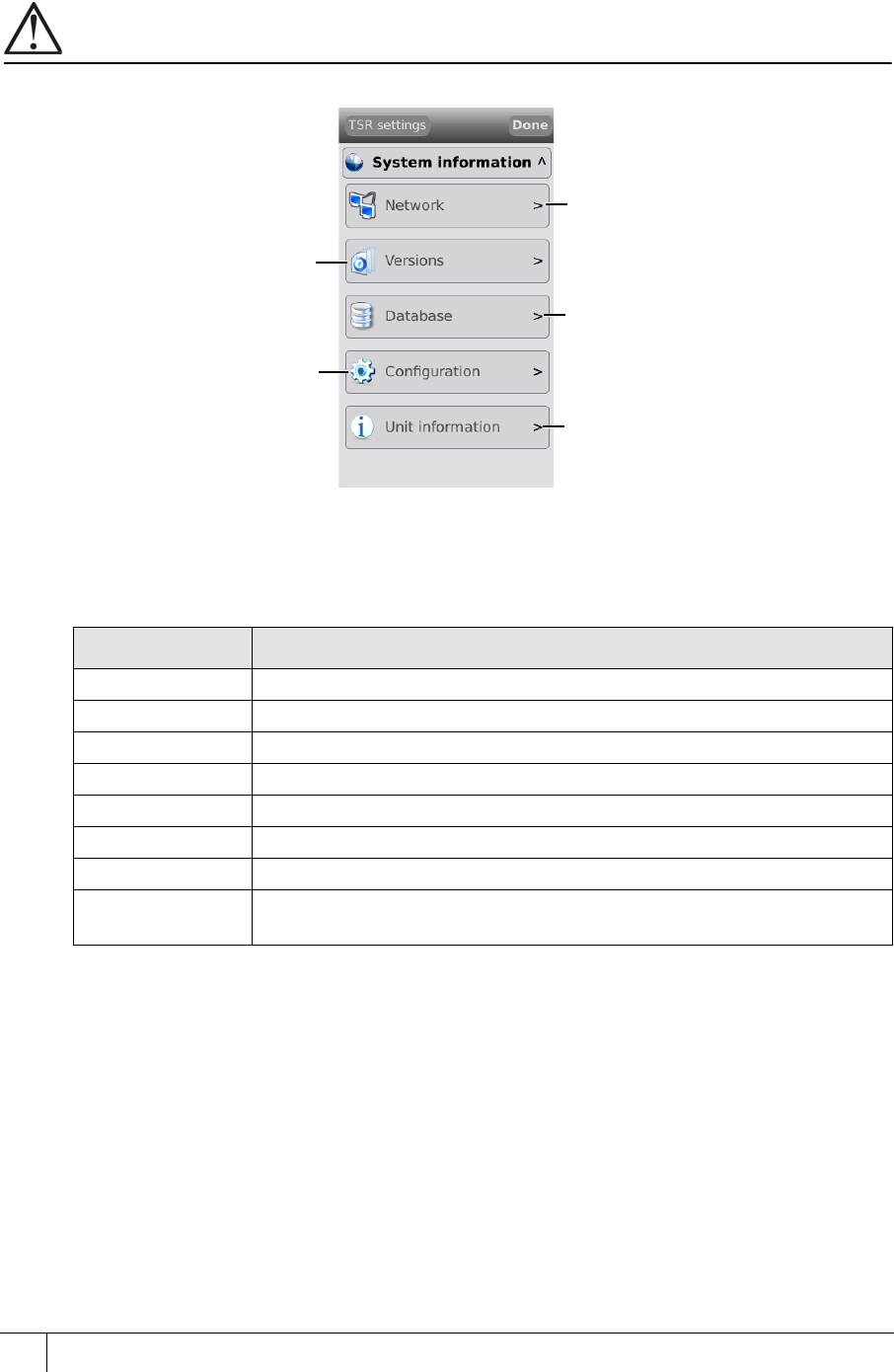
6.3.2 System Information menu
This menu contains information about the device including network, firmware version,
database and configuration.
Important
When contacting CEM support with any issues, this information may be asked for.
Network
The Network information section details all of the terminal network settings.
View terminal network
information
View firmware, software and
UI versions
View information about the
onboard cardholder database
View information about the
terminal device configuration View the status of terminal
connections, including
comms and tamper
Info Description
CEM address The CEM reader address of the terminal.
IP address The IP address of the terminal.
Subnet mask The subnet mask of the network hosting the terminal.
Default gateway The IP address of the gateway server.
MAC address The MAC address of the terminal.
RTC address The IP address of the RTC controlling the terminal.
VOIP server The IP address of the VOIP server for intercom functionality.
VOIP help station Intercom station number. This number is used to allow an intercom
workstation to communicate with the terminal.
Table 27: Terminal network information descriptions

emerald TS100/200/300 Installation Manual
53
Versions
The Versions information section details all hardware and software versions of the terminal.
Database
The Database information section details the information about the onboard card database.
Configuration
The Configuration menu provides information about terminal door modes.
Info Description
TSR Version Firmware version
UI Version User interface version
S/W Date Date of last firmware update
S/W Time Time of last firmware update on the S/W Date
H/W Version Version of the terminal hardware
H/W s/n Serial number of the terminal
Linux Linux kernel version, including date and time.
Qt Version of Qt library used by the UI.
Table 28: Terminal versions information descriptions
Info Description
CEM address The CEM reader address of the terminal.
Coldstart count Record of the number of times the terminal has been coldstarted.
Last coldstarted Date and time of the terminal’s last coldstart.
Card count Number of active cards held on the reader.
Last updated Date and time of the last database update from the server.
Trans all count Displays the number of buffered transactions and alarm events (in
offline mode). This is cleared when the terminal next goes online.
Trans card count Displays the number of buffered transactions only (in offline mode).
This is cleared when the terminal next goes online.
Last configured Displays the date and time that the terminal last received configuration
data from the server.
Table 29: Terminal database information descriptions
Info Description
Door mode Indicates the current door mode of the terminal. Standard Door,
Control Post, or Passenger mode.
PIN only TZ Displays a number to indicate which timezone is allocated as a PIN
only timezone.
Card only TZ Displays a number to indicate which timezone is allocated as a Card
only timezone
Door override TZ Displays a number to indicate which timezone is allocated as a Door
override timezone
Locked out TZ Displays a number to indicate which timezone is allocated as a Locked
out timezone
Table 30: Terminal configuration information descriptions
TSR-IM-0045-1.6
CHAPTER 6 : The System Configuration Menu
54
Unit information
The Unit information section provides information regarding the status of the terminal.
6.3.3 Tests menu
The emerald terminal has built in tests that can be performed to check specific functionality.
Important
When contacting CEM support with any issues, these tests may be requested.
Figure 42 The tests menu
Info Description
Tamper sensor Describes the status of the internal tamper switch.
Run time Information about the running time and load of the terminal.
Main comms Indicates the status of the main comms.
Database engine Indicates the status of the database engine.
Local inputs Indicates the status of the local inputs such as door position, lock
sense etc.
Main reader Indicates the status of the emerald master terminal.
Door interface Indicates whether a door interface unit is currently connected to the
emerald terminal.
2nd reader Indicates whether an exit reader is currently connected to the terminal.
Table 31: Terminal unit information descriptions
Test the terminal inputs
Test network settings
Display card for testing
LCD brightness and
display settings
emerald TS100/200/300 Installation Manual
55
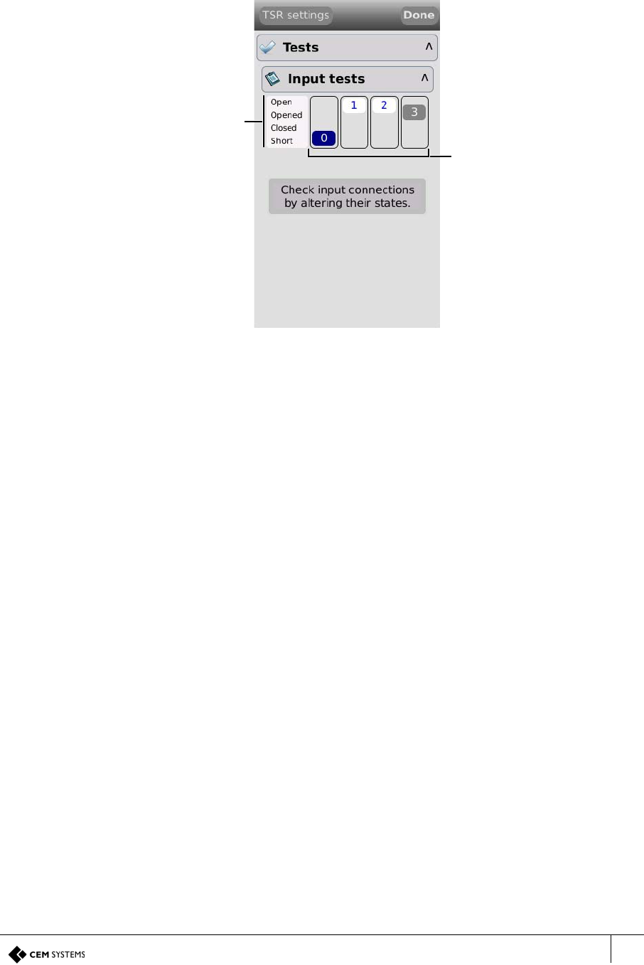
Input tests
The default Input tests screen displays the four terminal input states. When peripherals such
as an exit reader or door interface unit are attached to the terminal, their inputs will also be
displayed on the screen.
Figure 43 The input tests screen
Two state input test
When an input has been wired in a 2 state open and closed configuration only the Open and
Short tests can be administered.
Open - The input is opened.
Short - The input is closed.
Four state input test
When an input has been wired in a 4 state configuration as described in section 3.13.1 on
page 30, all four input state tests can be administered.
Open - Indicates a tamper cut condition.
Opened - The input is open.
Closed - The input is closed.
Short - Indicates a tamper short condition.
Inputs. Each number
correlates with a
terminal input number
as detailed in chapter
3. e.g input 0 is door
position.
The position of each
box corresponds with
an input state as
defined on the left of
the screen.
Input state. To test
the inputs, change the
state of the input e.g.
open and close the
door to test if the
terminal is registering
the state change.
TSR-IM-0045-1.6
CHAPTER 6 : The System Configuration Menu
56
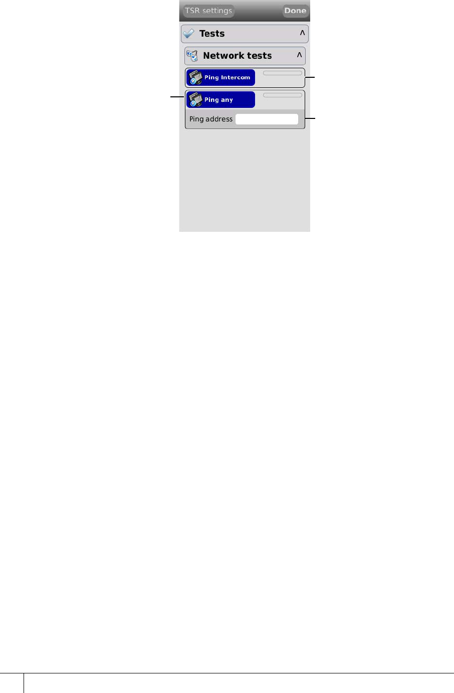
Network tests
The Network tests screen provides PING tests to check connectivity with the intercom server
and with any other provided IP address.
Figure 44 Terminal network tests
There are two possible responses for the ping utilities:
Red: No response received
Green: Response received
Press to PING the
intercom server
Press to Ping any to
PING the address
entered below Type an IP address to
PING with the Ping
any button
57
Chapter 7
Door Modes
The emerald terminal can be configured to function in different modes other than the standard
door mode described in the main section of the manual. The door modes are:
• Door mode including:
– Interlock
– Multi-swipe
• Control post
• Passenger mode including:
– Interlock
7.1 Door Mode
Door mode is the normal terminal configuration that is described in the main installation
section of this manual. It allows a terminal to control access to a door and monitor specific
inputs associated with that door.
7.1.1 Door mode timings
When a valid card is presented at a terminal in door mode, a chain of events takes place which
is dictated by specific settings in the Devices application. These timings are configurable in
the Devices application and also on the terminal itself.
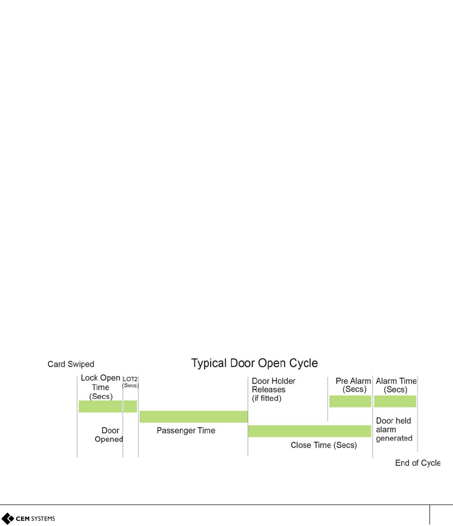
The door open cycle.
Figure 45 Illustration of typical door timings
A2SE67-UG-0011-1
CHAPTER 7 : Door Modes
58
1. The card is swiped at the terminal and access granted.
2. Lock power is dropped for a period of time known as Lock open time. (Five second
default) If the door is not opened by the end of this time, the lock re-engages.
3. After the door is opened by the cardholder the lock power remains off for a period of time
to prevent the lock re-engaging and closing the door before it is fully opened. This is the
Lock open time 2. (One second default)
4. The door is closed. If the door remains open longer than the Door close after time a door
held alarm will be generated on the terminal and the AC2000 system. (Default 15 seconds)
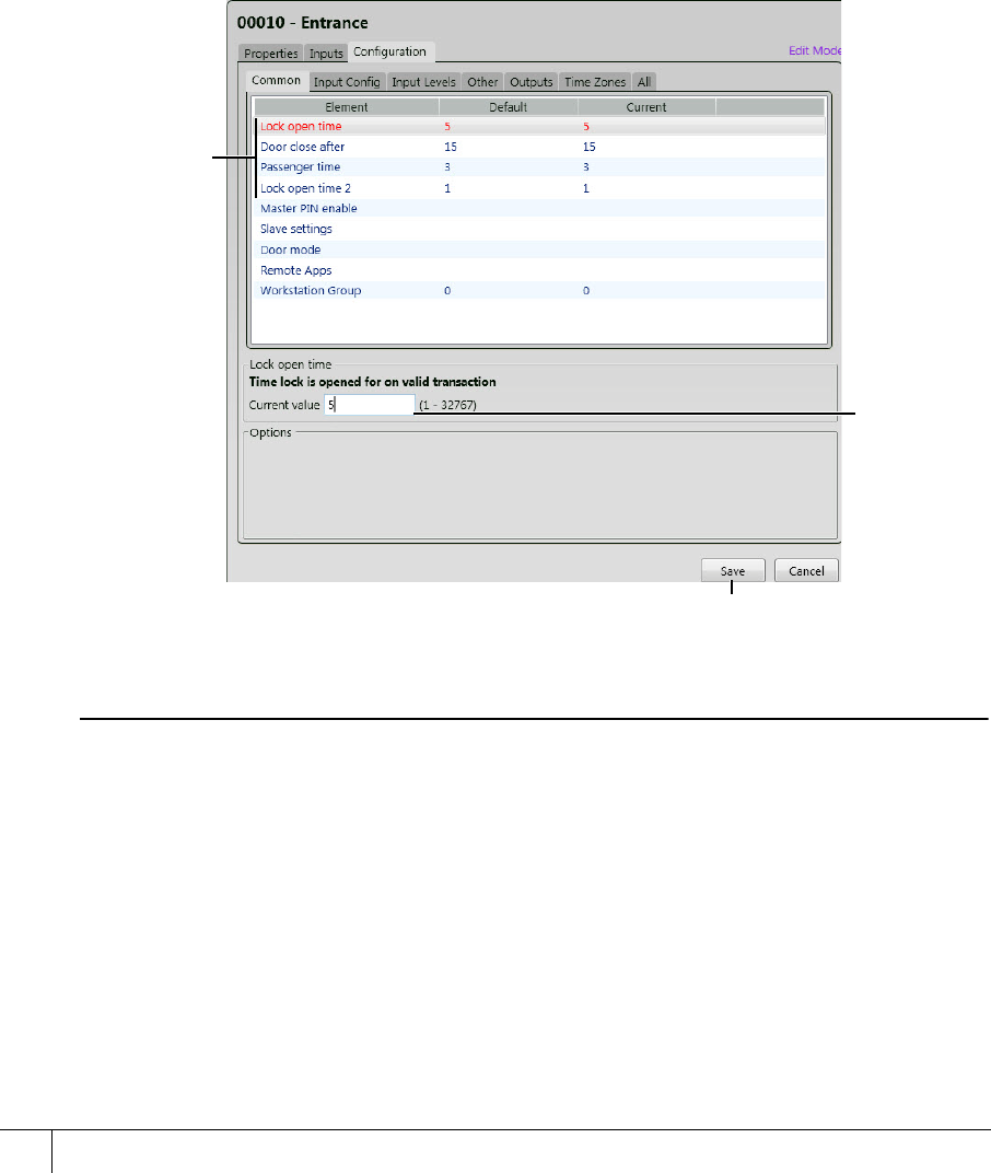
Configuring the timings in the devices application
1. From the Floatbar open Device Configuration | Devices.
2. Select the terminal from the list and open the Configuration panel.
3. Open the Common panel.
Figure 46 Updating the door cycle timings
Note
Configuration of other timings is covered in the appendices of this manual.
7.1.2 Multi-swipe access
The emerald terminal can be configured to require swipes from up to five valid cards before
granting access. This is configured using the Device application. Once this setting is
Select the
timing which
is to be
amended
Update the
value
required in
seconds
Click Save
AC2000 Getting Started Guide
59
configured, an initial valid swipe will prompt a request for further valid swipes on the screen
before opening the door. Once all valid cards are swiped the terminal will grant access.
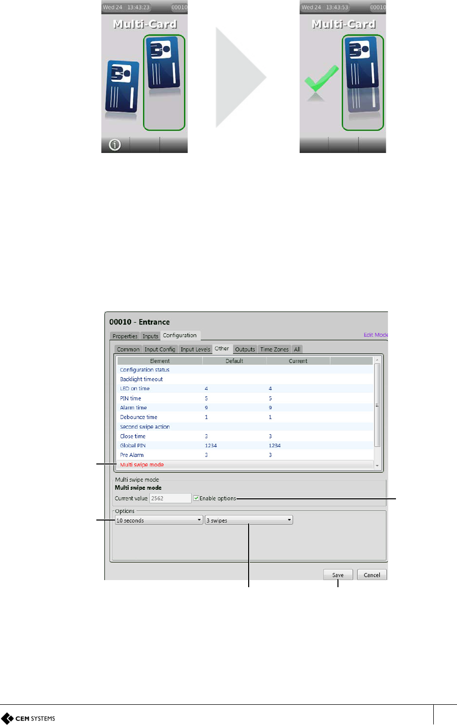
Figure 47 Multi-swipe request screen and access granted screen
The multi-card swipe screen will show the number of valid cards required to grant access, up
to a maximum of five cards. As each valid card is swiped a card image will move into the box
until all the required cards are swiped and access is granted.
Software configuration for multi-swipe access
1. From the Floatbar open Device Configuration | Devices.
2. Select the terminal from the list and open the Configuration panel.
3. Open the Other panel.
Figure 48 Configuring multi-swipe access
Select Multi
swipe mode
Place a tick
in Enable
options
Select the
maximum
wait time
between
swipes
Select the number
of swipes required
to open - max 5
Click Save
A2SE67-UG-0011-1
CHAPTER 7 : Door Modes
60
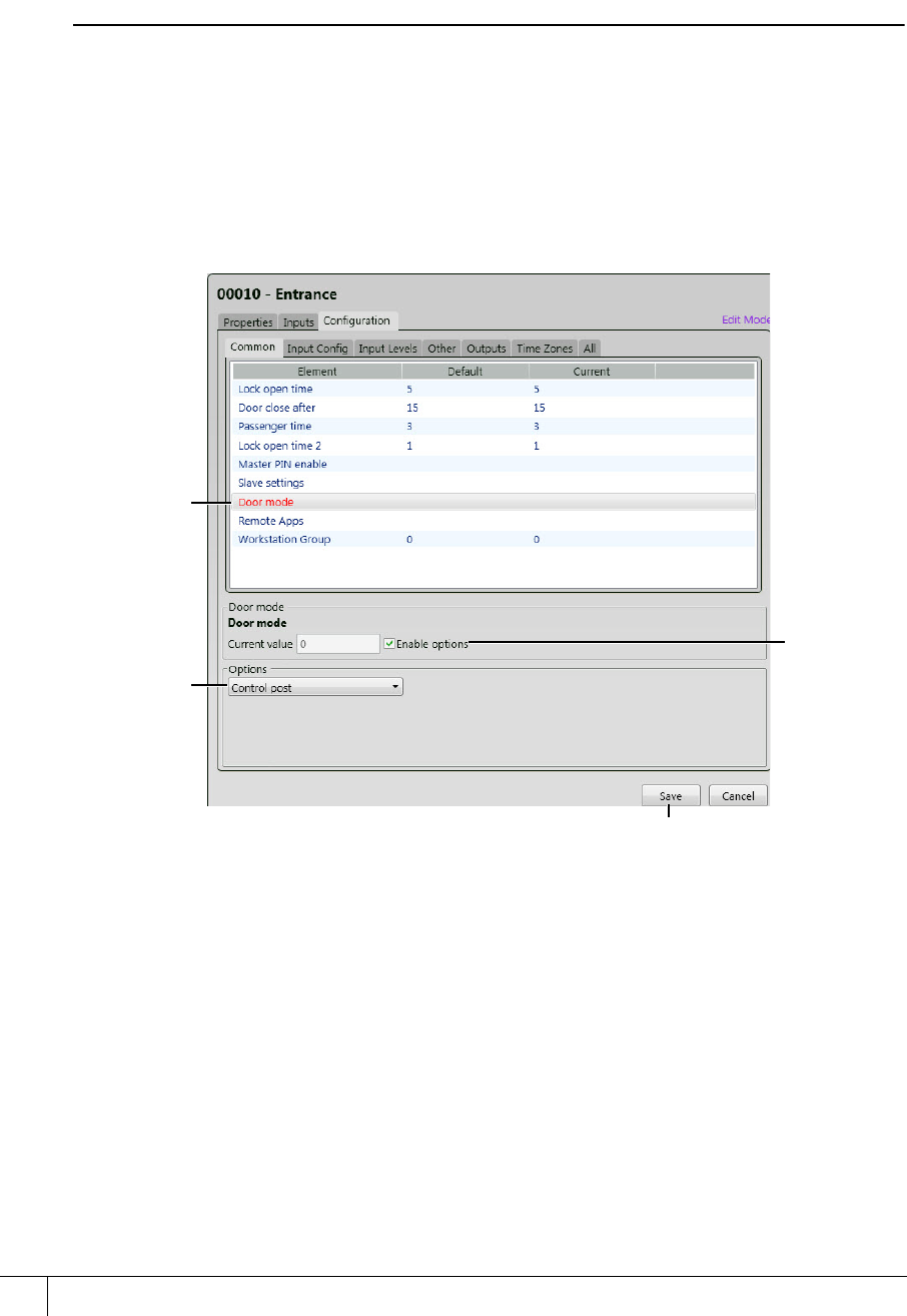
7.2 Control Post Mode
Control post mode places the terminal into a state where cards are swiped at a terminal with
no door equipment present. The terminal acknowledges the card but performs no other action.
Transaction logs are still maintained and all events can be observed in real time via the
Rolling Transaction Display application.
Note
All inputs may still be used as general purpose inputs and can be configured to trigger alarms
on the AC2000 software.
7.2.1 Software configuration for control post mode
1. From the Floatbar open Device Configuration | Devices.
2. Select the terminal from the list and open the Configuration panel.
3. Open the Common panel.
Figure 49 Configuring control post mode
Select Door
mode
Select
Control post
Click Save
Place a tick
in Enable
options
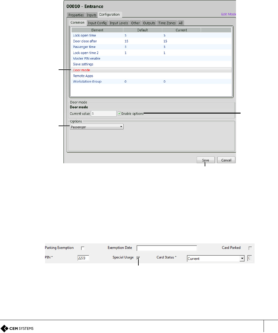
AC2000 Getting Started Guide
61
7.3 Passenger Mode
Passenger mode enables a door to stay open for a longer period of time when swiped with a
special usage card. This configuration is frequently used in airports to allow the free access of
passengers through the door.
7.3.1 Configuring passenger mode in the software
The terminal must be configured in passenger mode and cardholders allocated special usage.
Configuring the terminal as a passenger mode terminal
1. From the Floatbar open Device Configuration | Devices.
2. Select the terminal from the list and open the Configuration panel.
3. Select the Common tab.
Figure 50 Configuring passenger mode
Adding special access to a cardholder
1. From the Floatbar open Enrolment | Personnel.
2. Search for the cardholder to which the special access is to be applied.
3. Click the Edit button.
Figure 51 Adding special usage to a cardholder record
4. Place a tick in Special Usage.
5. Click Save.
Select Door
mode
Select
Passenger
Click Save
Place a tick
in Enable
options
Special Usage
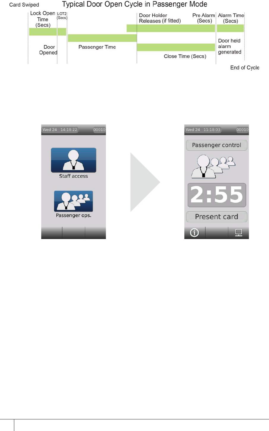
A2SE67-UG-0011-1
CHAPTER 7 : Door Modes
62
7.3.2 The passenger mode cycle
Figure 52 Illustration of passenger mode timing
1. A card with special usage allocated is swiped at a passenger mode terminal.
2. The terminal prompts whether Staff Access is required or Passenger ops. Selecting staff
access causes the terminal to act as in Door Mode.
3. Cardholder selects Passenger ops.
Figure 53 Pressing the passenger ops button
4. Lock power is dropped for a period of time known as Lock open time. (Five sec default) If
the door is not opened by the end of this time the lock re-engages.
5. After the door is opened the lock power remains off for a period of time to prevent the lock
re-engaging and closing the door before it is fully opened. This is the Lock open time 2.
(One sec default)
6. The terminal now enters Passenger Mode and the door may be held open for the period
of time as defined in the Passenger time before an alarm sounds. (Three min default)
7. Passenger Mode is deactivate by either: closing the door or swiping a valid special usage
card and selecting Cancel Access. This places the terminal back into Door Mode.
7.3.3 Lobby mode
Lobby mode is a combination of passenger mode and interlocking terminals. Two terminals
may be interlocked directly or more than two terminals may be interlocked via a third party
logic controller or interposing relays.
In lobby mode, as long as one door is open in passenger mode, interlocked doors will be
locked down to passengers but may be accessed with a valid card swipe.
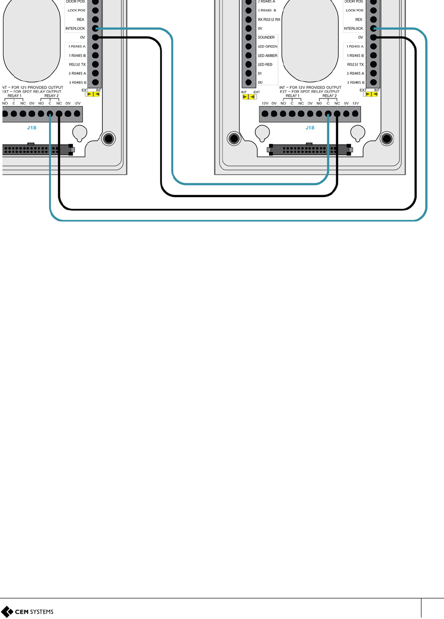
AC2000 Getting Started Guide
63
7.4 Interlock
Interlocking terminals are linked together so that only one terminal will open its door at any
given time. This is achieved using a combination of wiring and software configuration.
Interlocking between two terminals is achieved using a simple wiring configuration, however
interlocking more than two terminals requires the use of a third party logic controller or
interposing relay system.
7.4.1 Wiring two terminals for interlock
Figure 54 Wiring two terminals for interlock
Software configuration for interlock
1. From the Floatbar open Device Configuration | Devices.
2. Select the terminal from the list and open the Configuration panel.
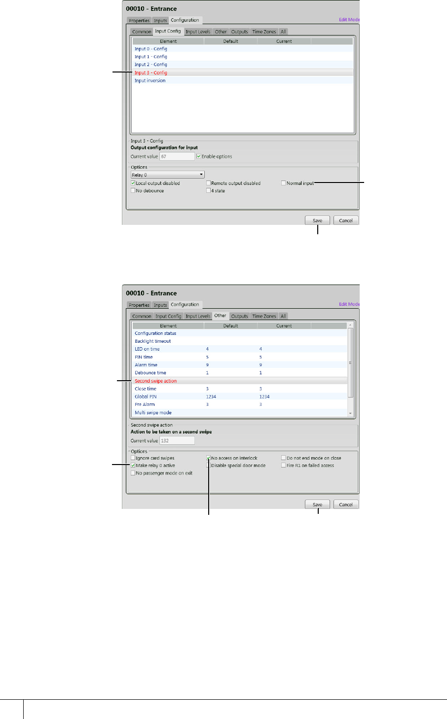
A2SE67-UG-0011-1
CHAPTER 7 : Door Modes
64
3. Open the Input Config panel.
Figure 55 Configuring input 3 for interlock
4. Open the Other tab.
Figure 56 Configuring interlock functionality
Select Input
3 - Config
(Input B
with DIU)
Remove the
check from
Normal Input
Click Save
Select
Second
swipe action
Place a tick
in Make relay
0 active
Place a tick in No
access on Interlock Click Save
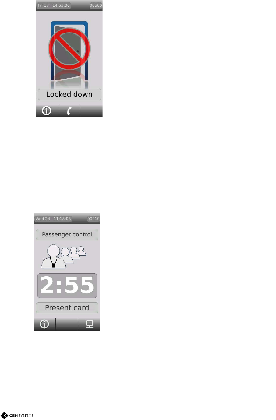
AC2000 Getting Started Guide
65
7.4.2 The interlock process in door mode
Interlock is configured and works the same way in Passenger Mode and Door Mode, with
only a slight change to end functionality.
7.4.3 The interlock process in passenger mode
1. The spare outputs of terminals are linked to input 3 of the other interlocked terminals.
2. When input 3 of the terminal is closed the terminal remains idle.
3. When a valid card is swiped at an interlocked terminal, both outputs on the terminal
change to the open state. This drops lock power at the swiped terminal and simultaneously
opens input 3 on any interlocked terminals.
Figure 57 Interlock locked down display
message in door mode
1. The spare outputs of terminals are linked to
input 3 of the other interlocked terminals.
2. When input 3 of the terminal is closed the
terminal remains idle.
3. When a valid card is swiped at an interlocked
terminal, both outputs on the terminal change
to the open state. This drops lock power at the
swiped terminal and simultaneously opens
input 3 on any interlocked terminals.
4. Interlocked terminals lock down and display
the lockdown message.
5. The interlock function ends when the original
swiped door is closed.
Figure 58 Passenger mode
countdown on the swiped
terminal
4. The swiped terminal displays a countdown screen
showing the time that the doors will remain interlocked.
(Passenger time in the Devices application)
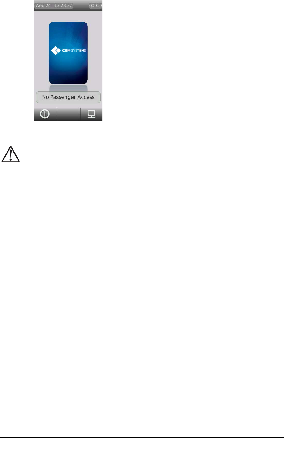
A2SE67-UG-0011-1
CHAPTER 7 : Door Modes
66
Important
If using a third party logic controller to control multiple doors, the interlock principles remain the same. The spare
output opens on a valid special usage swipe and input 3 is opened on interlock terminals to trigger lock down.
Figure 59 Interlock no passenger access
message in passenger mode
5. The interlocked terminals with input 3
now open will lock down, preventing
access until the swiped door is closed
or the mode ended. Interlocked
terminals will display a no passenger
access message. Normal card access
is allowed.
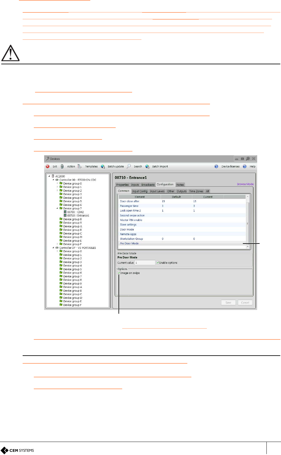
AC2000 Getting Started Guide
67
7.5 Image on Swipe
Image on swipe is enabled/disabled within Pre Door Mode configuration. When a cardholder
swipes a card on an emerald reader which has Image on swipe enabled, the cardholder’s
image is displayed on the screen. A security guard monitoring the reader will confirm if the
image on screen resembles the cardholder and select the green tick button to authorise
access or the red X button to deny access.
Important
If Image on swipe and Checklists are both enabled, Checklists can no longer be used.
7.5.1 Enabling Image on swipe
From the AC2000 Floatbar select Device Configuration | Devices.
1. Select the device from the list on the left that is to be configured.
2. Select the Configuration tab.
3. Select the Common tab.
4. Select Pre Door Mode from the list.
Figure 60 Enabling/disabling Pre Door Mode
5. In the Configuration panel, select the Enable options tick box to enable Pre Door Mode.
Note
Enabling Pre Door Mode activates the associated Options.
6. From the Options, select the Image on swipe checkbox.
7. Press Save to save all changes.
Pre
Door
Mode
Image on swipe option
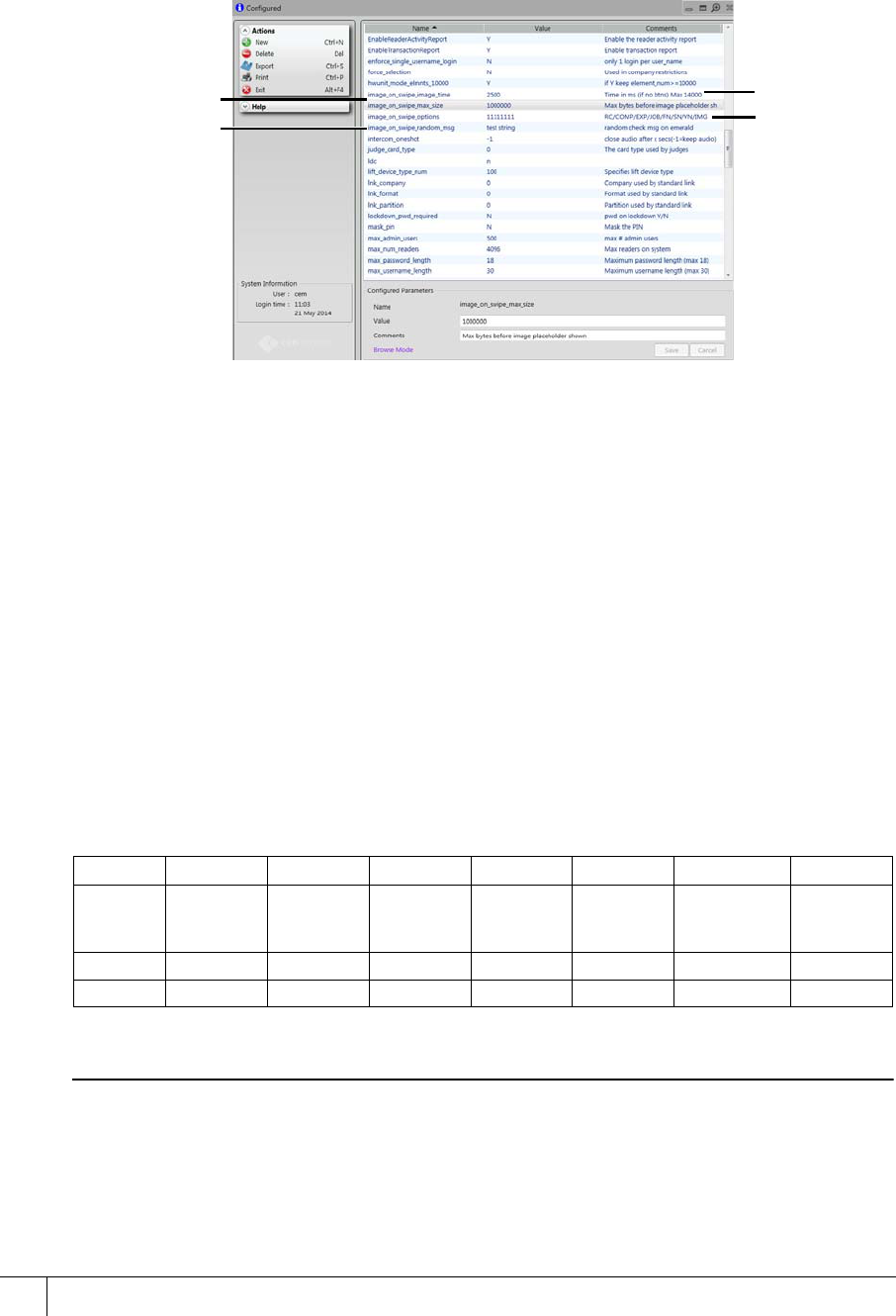
A2SE67-UG-0011-1
CHAPTER 7 : Door Modes
68
7.5.2 Configuring Image on swipe options
When Image on swipe is enabled and a cardholder presents a valid card at the emerald
reader, their cardholder details are displayed below the image. The details displayed are
determined by settings in the Configured application in AC2000.
1. From the AC2000 floatbar select Advanced Configuration | Configuration.
Figure 61 Configuring Image on swipe settings
2. Select the image_on_swipe_image_time field. This is the length of time the image will
display on the emerald reader and it is counted in milliseconds.
3. Type a Value e.g. 2500 (2.5 seconds).
4. Select the image_on_swipe_max_size field. This is the maximum image size in MB that
can be uploaded to display on the emerald reader. If the image is larger than this value, an
image placeholder is displayed. To ensure the image displays correctly, use a lower value
on slower network connections.
5. Type a Value e.g. 100000
6. Select the image_on_swipe_options field.
7. Type a Value. The default value is 01011111. The following table displays an example of
the default Value for the Image_on_swipe_options field. If a value is enabled it will
display when the user swipes a card at the emerald reader. If the value is disabled it will
not appear on the reader when a card is swiped.
Example of the deafult value for the Image_on_swipe_options field
Note
For more information on random checks, see section 7.5.2 Random Checks in this manual.
8. Select the image_on_swipe_random_msg field. This is the message that is displayed
when the cardholder swipes a valid card on the emerald reader when they have been
selected for a random check.
9. Type a Value e.g. send for drugs test.
RC COMP EXP JOB FN SN YN IMG
Random
check
Company Expiry
date
Job title First name Surname Confirmation
buttons
(Yes/No)
Image
display
010111 1 1
Disabled Enabled Disabled Enabled Enabled Enabled Enabled Enabled
Table 32: Example of the default value for the Image_on_swipe_options field
Image time
Max size Options
Random
message
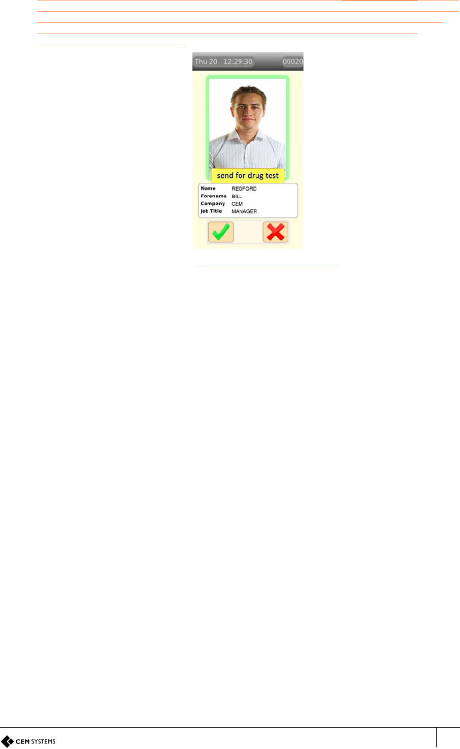
AC2000 Getting Started Guide
69
The next time that a card is swiped on the reader which has had the Image on Swipe function
activated, the image associated with that card will display on the emerald screen. Tapping the
green tick on the screen indicates that the image on screen resembles the cardholder and
access is granted. Tapping the red X indicates that the image does not resemble the
cardholder and access is denied.
Figure 62 Image on Swipe display on screen
Viewing cardholder details
There are several options available for viewing the cardholder information on the emerald
screen. Use a sequence of tapping the image to view the information as described below:
• To view the image and cardholder details, tap the image once
• To view a smaller image and a larger text display, tap the image twice
• To view a larger image and minimal text display tap the image three times
• To view more cardholder details in the list below the image, press and hold your finger on
the screen and drag the text area in a scrolling motion
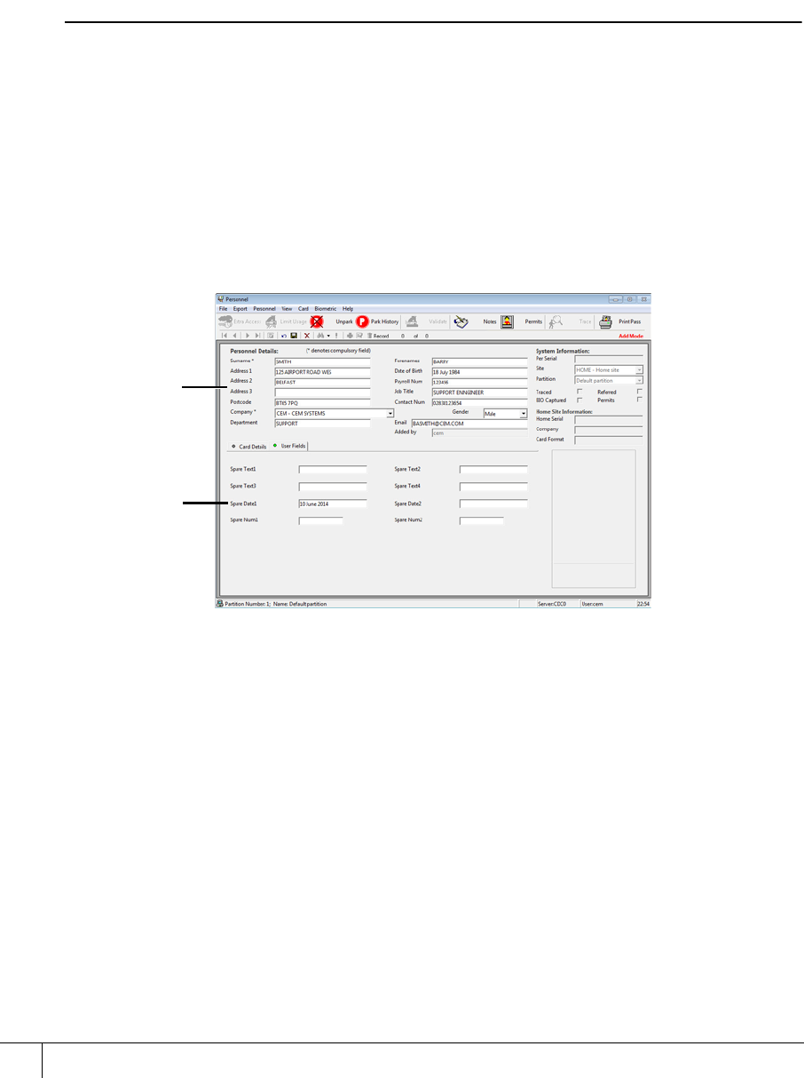
A2SE67-UG-0011-1
CHAPTER 7 : Door Modes
70
7.5.3 Random checks
In certain situations, it may be necessary to perform other checks in addition to authenticating
a cardholder’s card and confirming their identity as previously described. If appropriate, your
system administrator should implement this procedure and configure the system accordingly.
Example: A system administrator configures the system to prompt security guards using an
emerald reader that some cardholders need to be tested for drugs. When a cardholder who
has been selected for a random check swipes on a reader, a message will display on the
emerald screen stating the required action.
Note
The prompt displayed can be configured to read something other than Drugs test. For
example a construction site may prompt a security guard to Check PPE (Personal protective
equipment) for adherence to company policy, or an airport might use the Search prompt to
manage search ratios. The system administrator will advise you regarding procedures for the
configured prompts.
Confirming the random check completion
When a cardholder is selected to receive a random check, the date when they are selected is
displayed in the Spare date1 field in the cardholder’s records in Personnel. A new set of
cardholders are selected for a random check every day and the date entry on the personnel
file indicates the date that each cardholder was selected.
Figure 63 Personnel record dislaying Spare Date1
The person who executes the random check (ie. security guard or medical nurse) must have
access to the Personnel application in AC2000 so that this date field can be cleared, upon
successful completion of the random check. Failure to do so will cause the random check
prompt to be displayed every time the cardholder swipes their card from that point in time on.
To clear the message prompt following successful completion of the random check:
1. Open a workstation and log in to AC2000.
2. From the Floatbar, select Enrolment | Personnel.
3. Locate the cardholder:
a. Select Search.
b. Enter any appropriate search criteria (eg. name).
c. Select Query Database.
Spare Date1
Personnel
record
details

AC2000 Getting Started Guide
71
d. If no search criteria is entered, acknowledge the warning message that is
displayed by selecting Ignore.
e. Use the navigation arrows to locate the correct cardholder record from results
returned from the search (if required).
4. From the Database Toolbar, select Edit.
5. Click on the User Fields tab.
6. Delete the date entry in the Spare date1 field.
7. Select Save.
The random check prompt has now been cleared from the cardholder’s Personnel record.

A2SE67-UG-0011-1
72
This page is intentionally blank.
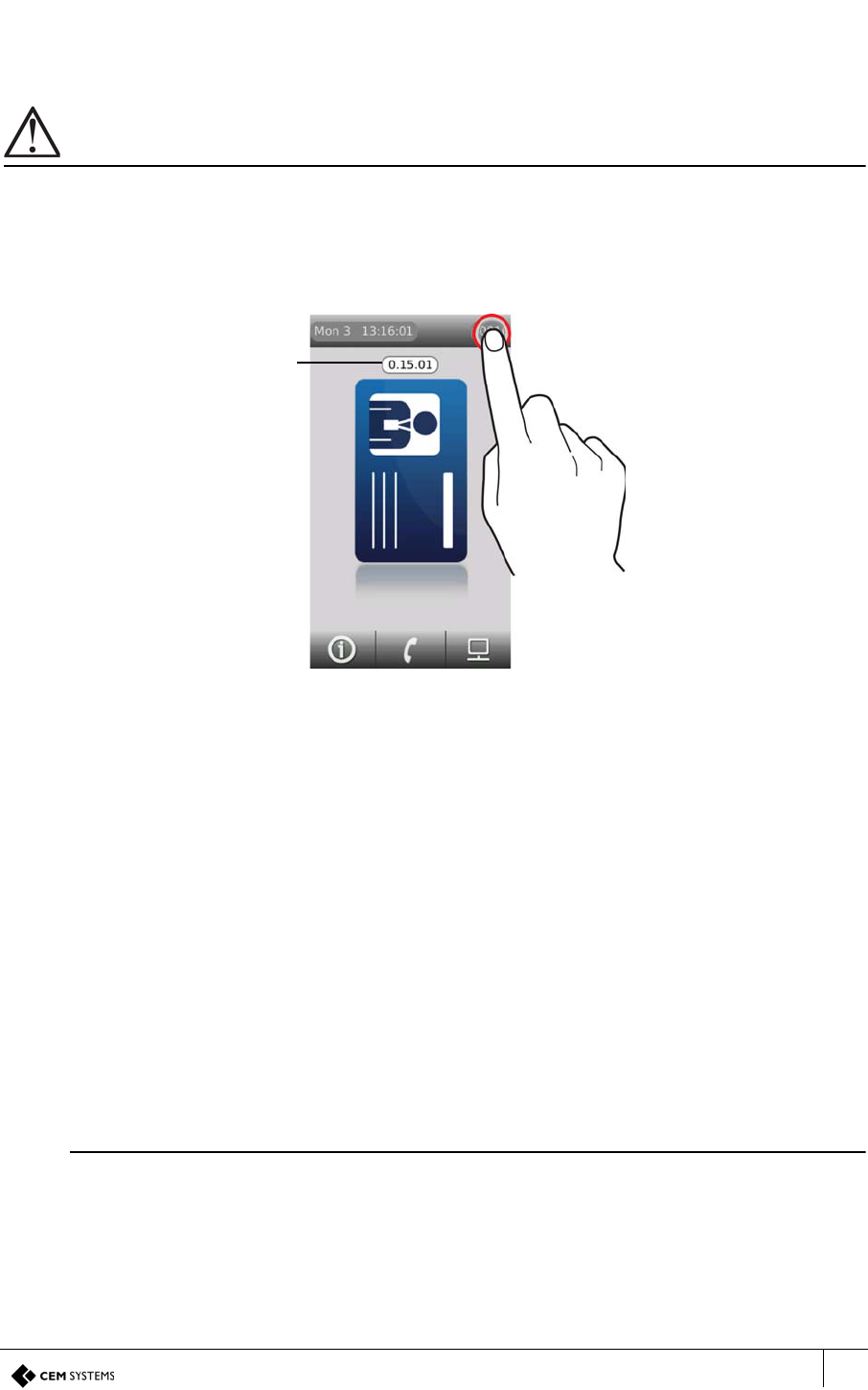
emerald TS100/200/300 Installation Manual
73
Appendix I: Updating Firmware
Updating the emerald terminal firmware (device defrosting) is accomplished by using the AC2000 web
pages to load the firmware pack on to the terminal and then manually updating the terminal.
Important
This process should only be carried out by an AC2000 administrator with relevant permissions.
Checking the firmware version of the terminal
Press and hold the reader address
Figure 64 Checking the terminal firmware version
Loading the firmware onto the terminal(s)
1. Obtain the firmware pack from CEM and save to an accessible location on the network.
2. Log into the web pages by opening a web browser.
3. Enter the Server IP Address, e.g.
https://192.168.1.10
If the IP address has been changed from the default, enter the new IP address.
4. Enter the username and password.
5. Click Login.
6. Select AC2000 WEB | Reader Setup | Device Defrost
7. Click Browse and select the device image file (.pak) that is to be loaded.
Note
This image will be provided by CEM support and should be saved in a secure location.
8. Click Upload
9. Click OK.
The firmware version is
displayed for as long as
the press is held on the
reader address
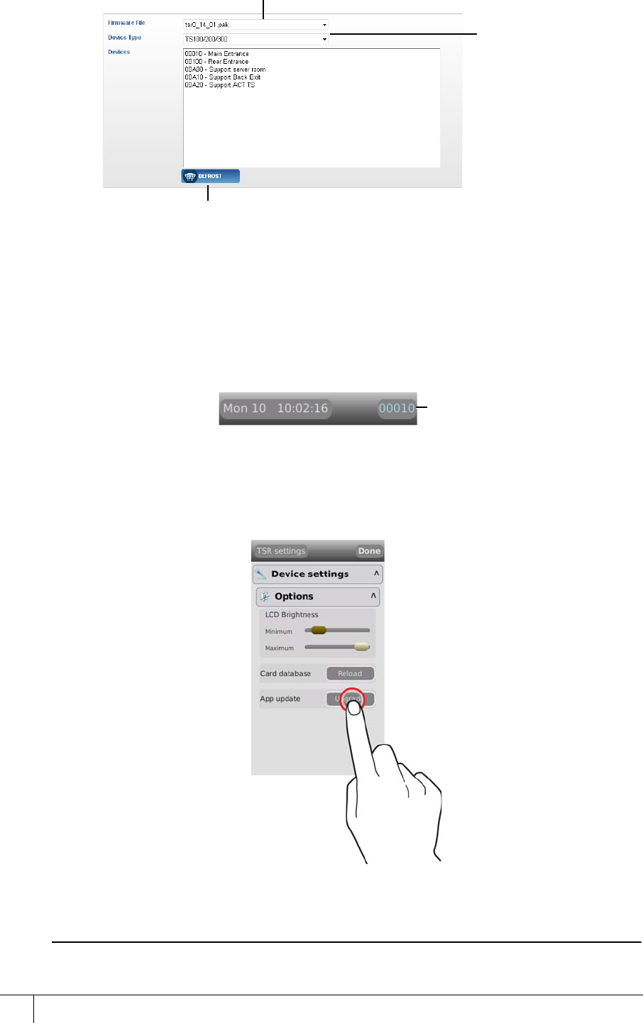
TSR-IM-0045-1.6
74
Figure 65 Selecting devices to defrost
A message will appear similar to the following:
Initiating defrost to device:XXXX with firmware file:<filename>
Updating the terminal
Once the terminal has received the firmware file, the reader address will be displayed in cyan
instead of white.
Figure 66 Cyan reader address
1. Access the terminal System Configuration menu.
2. Open Device settings | Options.
3. Press Upgrade.
Figure 67 Upgrading the terminal firmware
The reader will update and reboot.
Note
The reader will go offline momentarily whilst the upgrade takes place.
Select the firmware image
Select the device type to be
defrosted. This should match the
firmware file type
Select the devices to be defrosted.
Hold Ctrl + click multiple devices if
required.
Ensure that the selected devices
are of the correct type.
Click defrost to complete the process
Reader address
displayed in cyan
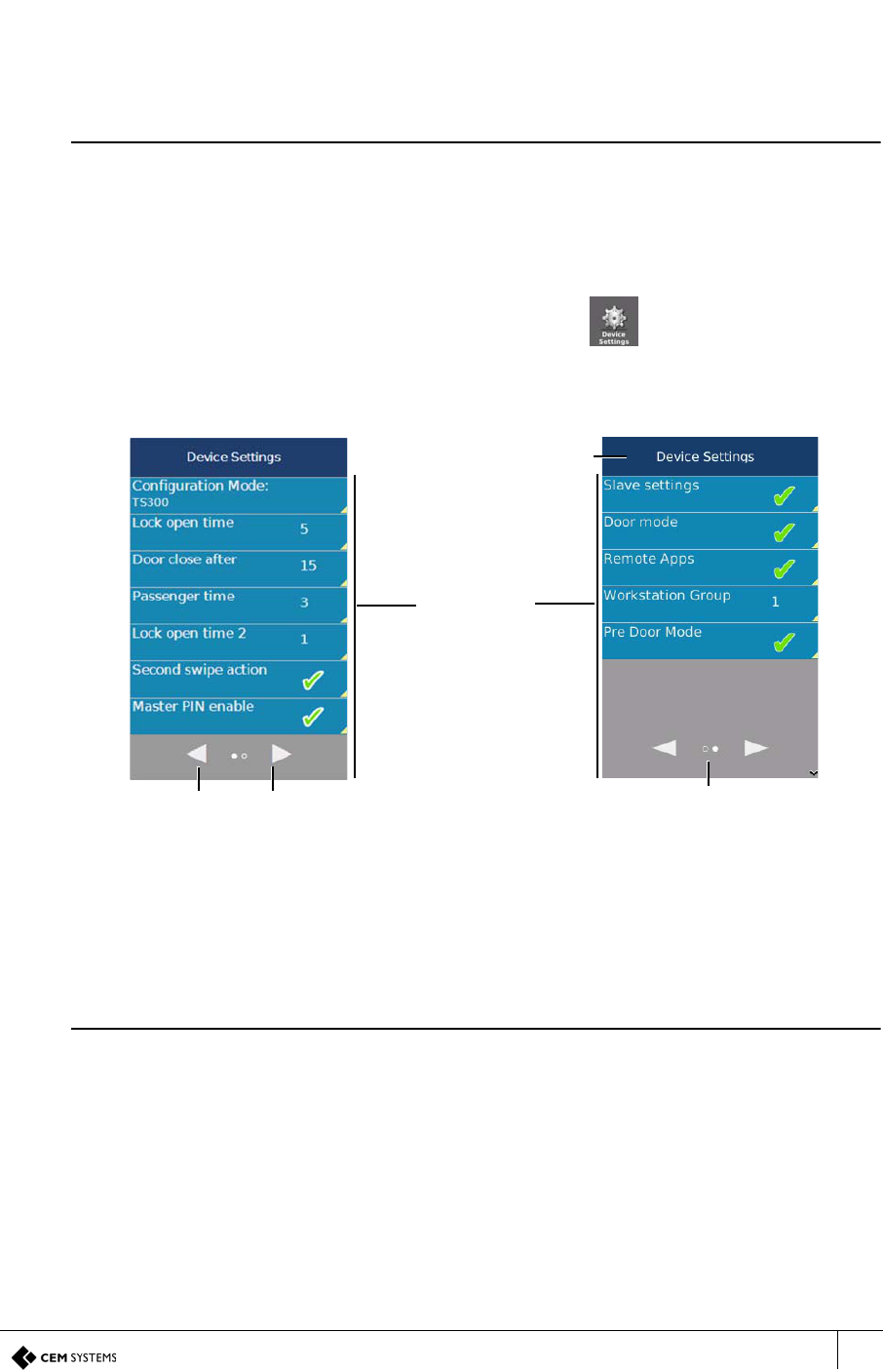
emerald TS100/200/300 Installation Manual
75
Appendix II: Device Settings Remote
Application
The Device Settings Remote Application is used to adjust specific terminal settings that would
ordinarily be carried out in the Devices application of AC2000.
Note
For information about configuring Remote Applications see the emerald User Guide.
Using the Application
1. Using a card which has the relevant permissions to access the Device Settings Remote
Application, press the Remote Applications icon and swipe the card when requested.
2. Press the Device Settings icon to open the application.
The configurable options are displayed in a two page list. The user can navigate between
pages by tapping the Next page or Previous page buttons. The number of pages in the list
are indicated by the number of dots between the Next page and Previous page buttons. The
filled dot represents the one currently in view on the screen.
Figure 68 The device settings remote application
3. Tap the option to be adjusted to open settings editor mode
4. Configure the settings as required (See Configuring the options).
5. Press the Save button to save changes made to each setting.
Note
In settings editor mode, a Save changes button is displayed at the top of the screen and the
symbol on the back button becomes red to indicate that going back without pressing Save
changes will cause any changes made to be lost.
Previous
page
button
Next
page
button
Page navigation
indicator
Back button
Tap any row
to edit
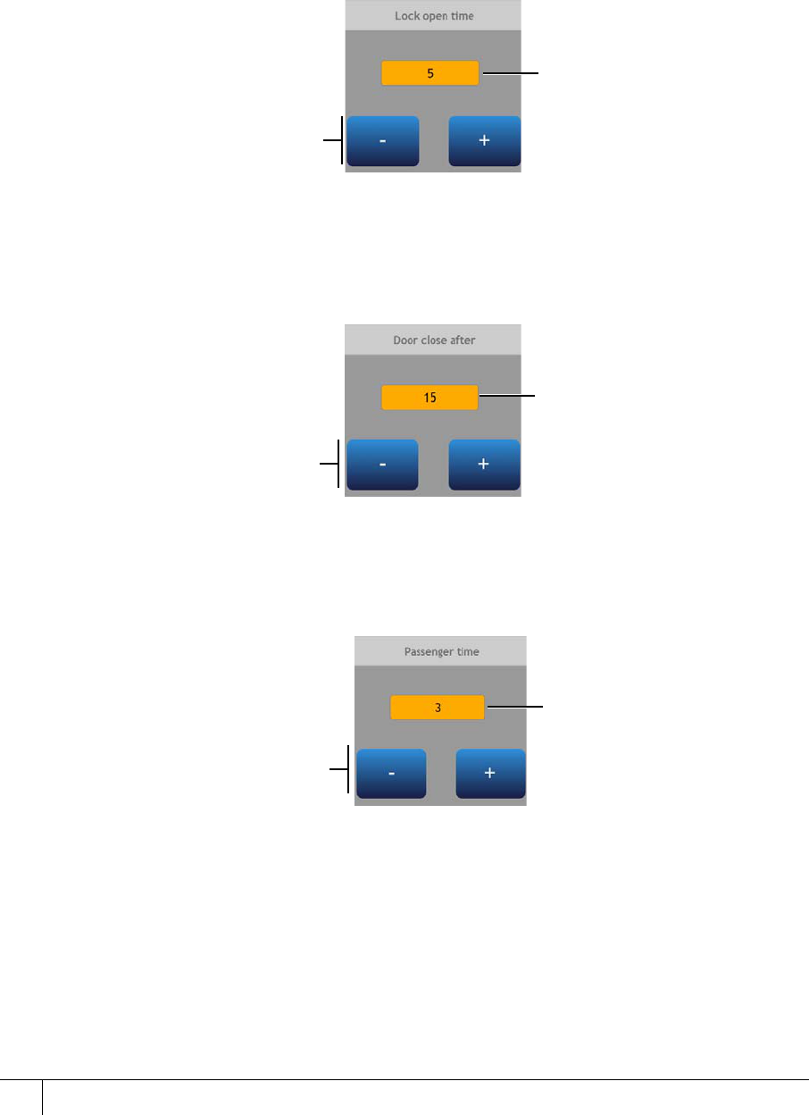
TSR-IM-0045-1.6
76
Configuring the options
There are nine options that may be configured via this application. All changes made on the
terminal are saved on the AC2000 server. After changes are made, press the save button.
Lock open time
Lock open time sets the length of time in seconds that the lock power will drop when a valid
card is swiped.
Figure 69 Configuring the lock open time
Door close after
Door close after time sets the length of time in seconds that the door may be held open after a
valid card swipe before a door held alarm is generated.
Figure 70 Configuring the door close after time
Passenger time
Passenger time sets the length of time in minutes that the door may be held open in passenger
mode before a door held alarm is generated.
Figure 71 Configuring the passenger time
Adjust the time in one second
increments by tapping the
plus and minus buttons
Time in seconds
Time in seconds
Adjust the time in one
second increments by
tapping the plus and minus
buttons
Adjust the time in one second
increments by tapping the
plus and minus buttons
Time in seconds
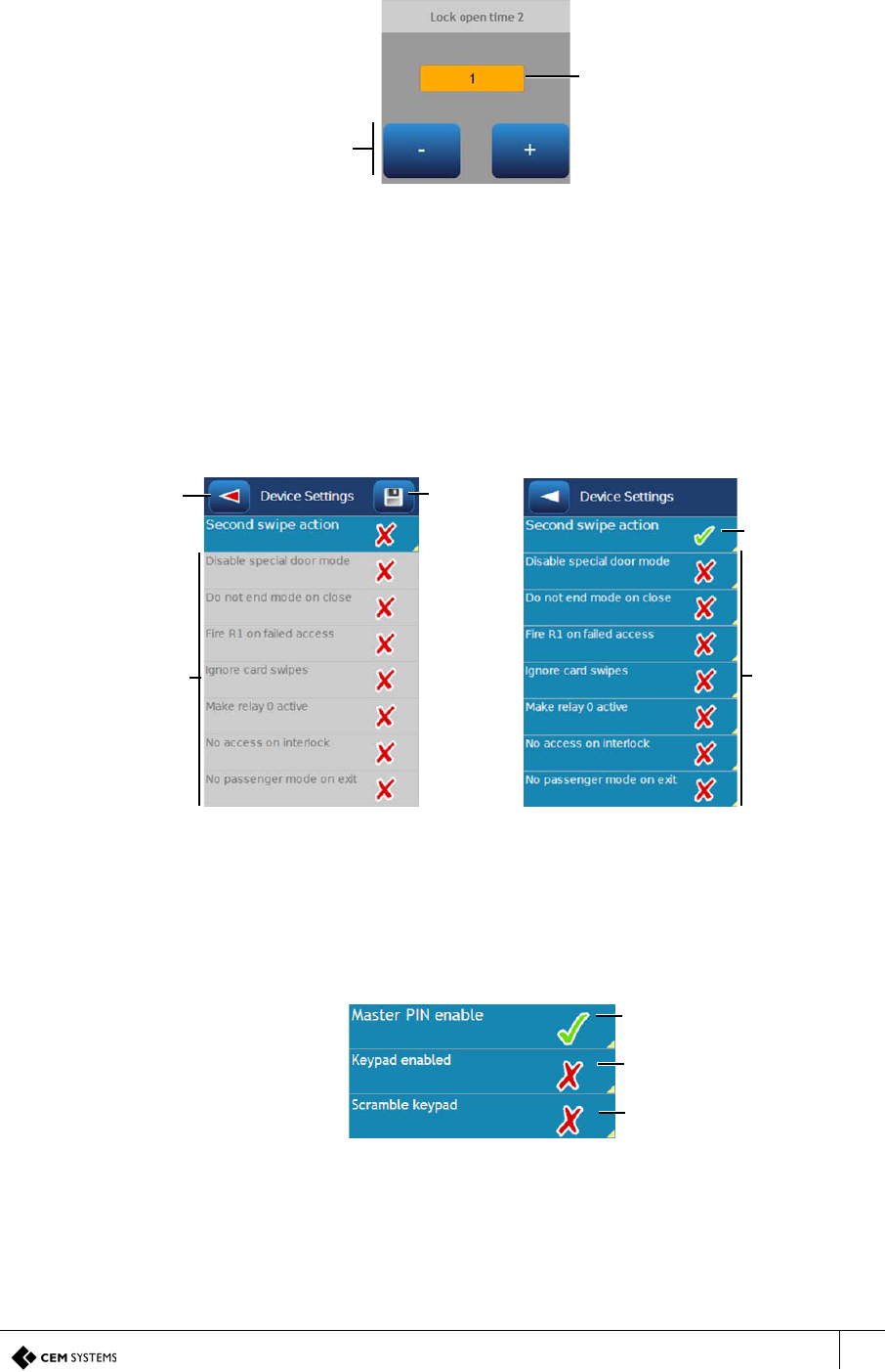
emerald TS100/200/300 Installation Manual
77
Lock open time 2
Lock open time 2 sets the length of time in seconds that the lock power remains off after the
door is opened to prevent the lock accidentally re-engaging.
Figure 72 Configuring the lock open time 2
Second swipe action
Second swipe action is used to enable an alternative action within a door mode e.g. If a reader
is in Passenger mode and Disable special door mode is enabled, using a special card as a
second swipe will disable interlock mode and the door will remain open for the specified time.
indicates that the setting is enabled
X indicates that the setting is disabled
Figure 73 Configuring second swipe action
Master PIN enable
Enable the PIN controlled access at the terminal.
indicates that the setting is enabled
X indicates that the setting is disabled
Figure 74 Configuring the master PIN settings
Time in seconds
Adjust the time in one second
increments by tapping the plus
and minus buttons
Back button
(without saving
changes
made)
Save
changes
Sub- elements
disabled when
main setting is
turned off
Sub- elements
enabled when
main setting is
turned on
Tap to
enable/disable
Second swipe
action
Tap to enable/disable master
PIN settings
Tap to enable/disable the
terminal keypad
Tap to enable/disable a
scrambled keypad as an
additional security measure
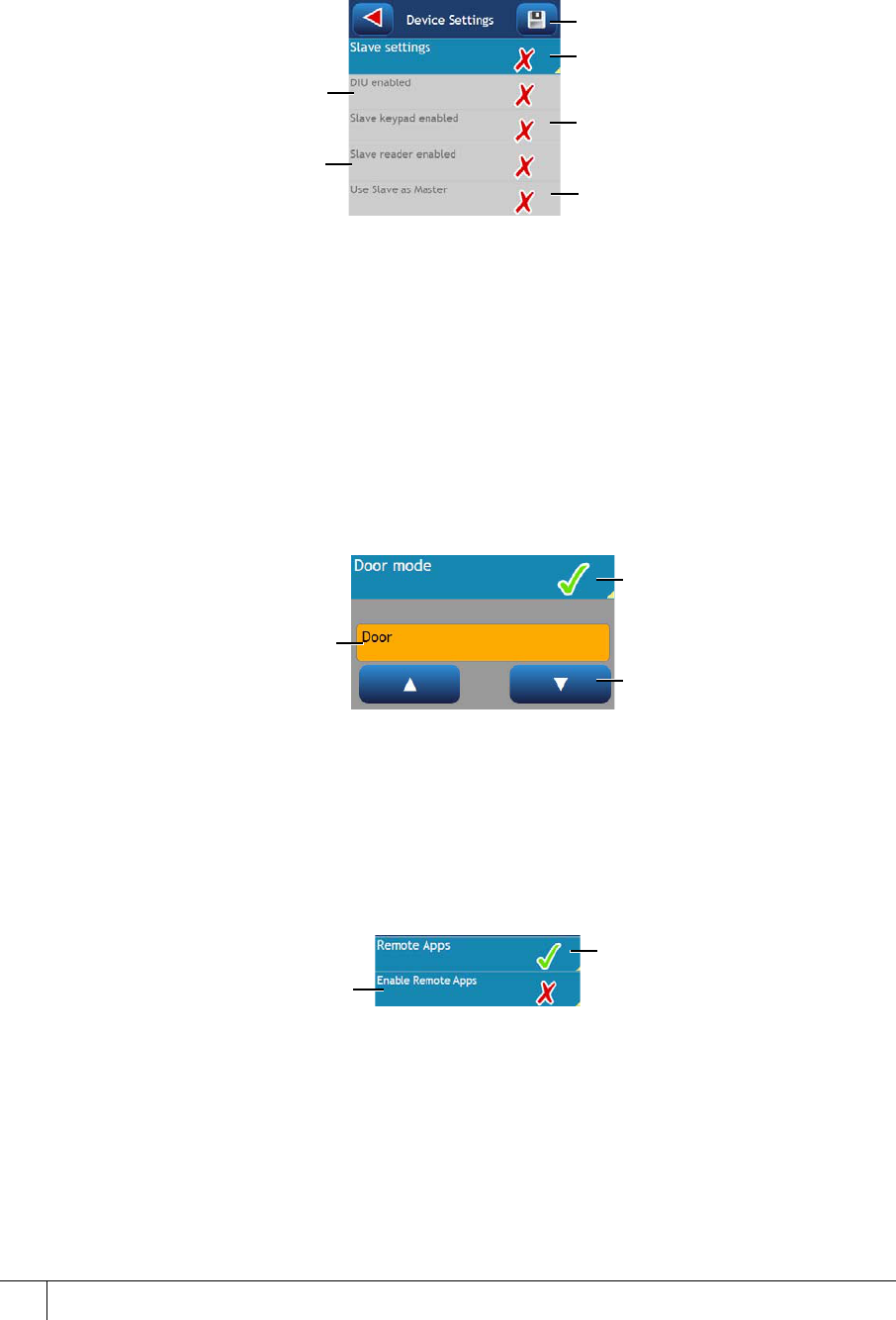
TSR-IM-0045-1.6
78
Slave settings
Toggle settings for any connected slave devices.
indicates that the setting is enabled
X indicates that the setting is disabled
Figure 75 Configuring the slave settings
Door mode
The door mode option is used to toggle between the available door modes:
• Door mode
• Control post
• Passenger mode
indicates that door setting mode is enabled
X indicates that door setting mode is disabled
Figure 76 Configuring the door mode setting
Remote Applications
The Remote Applications option is used to enable/disable Remote Application functionality for
the terminal.
indicates that the setting is enabled
X indicates that the setting is disabled
Figure 77 Configuring the remote applications setting
Tap to enable/disable
slave settings
Tap to enable/disable the
keypad the S610s slave
Tap to enable/disable an
attached S610s slave
Tap to enable/disable
an attached DIU
Tap to use the slave as
the master reader
Tap to save changed settings
Currently configured
door mode
Tap to enable/disable door
mode settings
Use the arrows to scroll
through available door modes
Tap to enable/disable Remote
Applications settings
Tap to enable/disable
Remote Applications on
the terminal
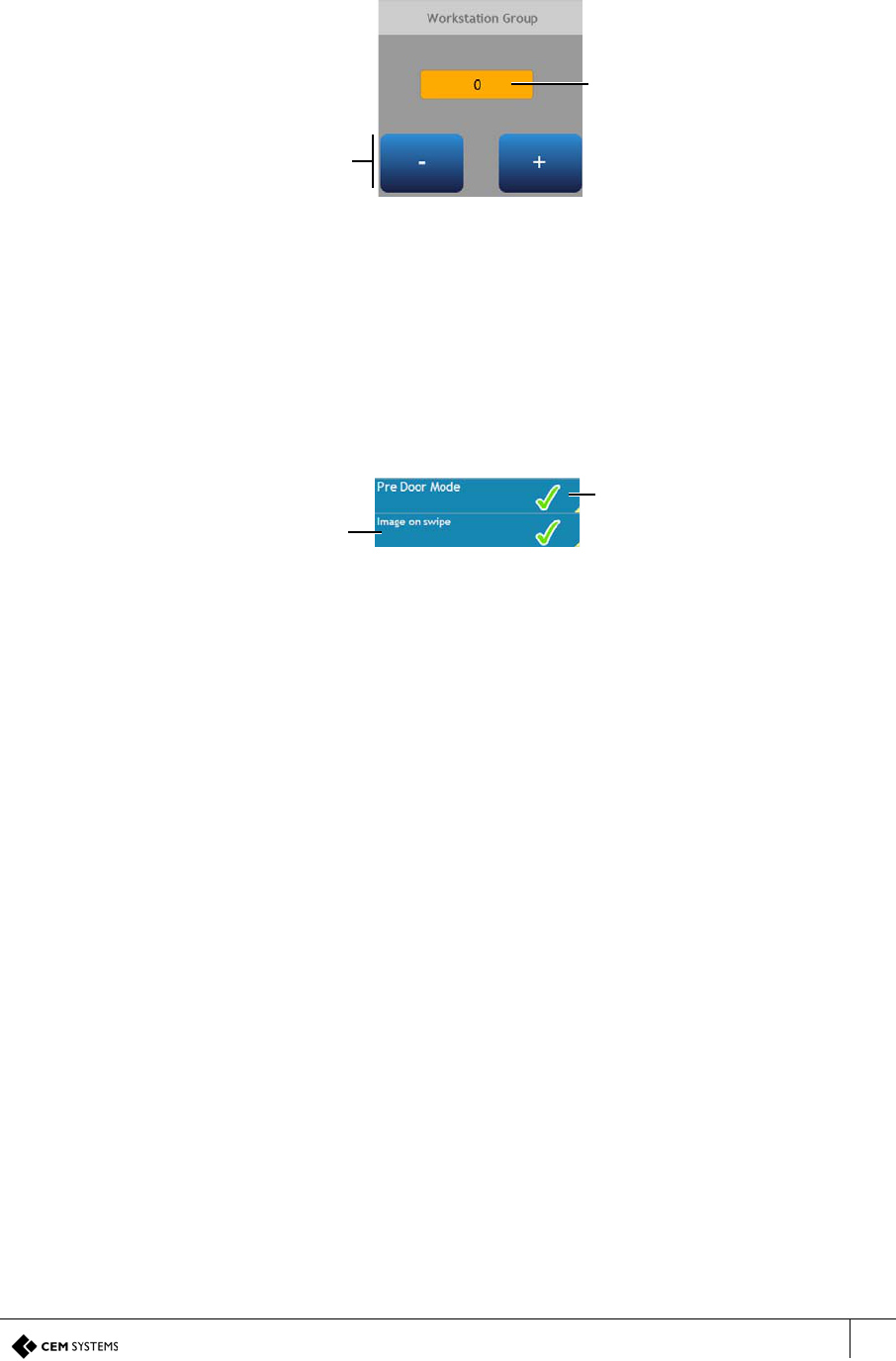
emerald TS100/200/300 Installation Manual
79
Workstation group
The workstation group option is used to assign an intercom workstation group to the terminal.
The terminal intercom function can only communicate with workstations assigned the same
workstation group number.
Figure 78 Configuring the workstation number setting
Pre Door Mode
The Pre Door Mode option is used to enable/disable Pre Door Mode functionality for the
terminal, including Image on Swipe.
indicates that the setting is enabled
X indicates that the setting is disabled
Figure 79 Configuring the Pre Door Mode setting
Current workstation
group number
Adjust the workstation
group by tapping the
plus and minus buttons
Tap to enable/disable Pre
Door Mode options
Tap to enable/disable
Image on Swipe mode
on the terminal

TSR-IM-0045-1.6
80

emerald TS100/200/300 Installation Manual
81
Appendix III: Broadcast and Timezone
Priorities
A state machine is used to determine the priority that different events such as broadcast and timezone
changes have on the terminal. The order is listed below in descending priority:
1. Broadcast open
2. Interlock input
3. Locked out TZ (timezone)
4. Door override TZ (timezone)
5. Card only TZ (timezone)
6. PIN only TZ (timezone)
Example
If there is an overlap between the Locked out TZ and the Card only TZ, the Locked out TZ
will take priority due to it being higher up the list. Once the Locked out TZ ends the Card only
TZ will take over.
Regardless of which state the terminal is in, a Broadcast open will open the door, overriding
all other options.
Note
For more information on Timezones consult the AC2000 Setup Guide, and for information
about Broadcasts consult the AC2000 Operator Guide.

TSR-IM-0045-1.6
82
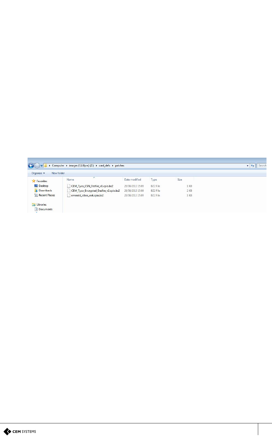
emerald TS100/200/300 Installation Manual
83
Appendix IV: Loading Card Definitions
In order for AC2000 to correctly process the information encoded on the smart cards the correct card
definitions must be loaded onto the CDC. These are loaded via the AC2000 Web pages.
1. Log into the AC2000 client software. This is done to allow access to the definition files on
the CDC.
2. Log into the web pages by opening a web browser.
3. Enter the Server IP Address, e.g.
https://192.168.1.10
If the IP address has been changed from the default, enter the new IP address.
4. Enter the username and password.
5. Click Login.
6. Select AC2000 WEB |System | Software Update
7. Click Browse and navigate to Z:\\card_defs\patches.
8. Select the device image file (.cpio.bz) that is to be loaded.
Figure 80 Card definition file list
9. Click Upload
10. Click OK.

TSR-IM-0045-1.6
84
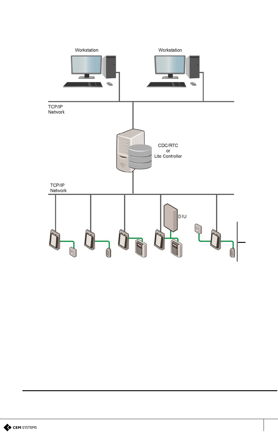
emerald TS100/200/300 Installation Manual
85
Appendix V: Configuring a Third Party Reader
as a Master
It is possible to configure an emerald with a third party read head as a master reader. This
configuration may be used in a system where two card technologies are in use and it is
necessary to have two read head technologies on the same side of a door. An exit request
(REX) switch may be used to control egress via the same door.
Figure 81 Possible system configurations
Hardware installation
For detailed wiring information, please refer to the following sections:
• Terminal with 3rd Party Wiegand Read Head on page 20
• Terminal with Request to Exit Switch on page 18
Software configuring
1. From the Floatbar open Device Configuration | Devices.
2. Follow the procedure for adding a TS100/TS200/TS300 device as described in Adding the
device to AC2000 on page 38.
Note
In the Configuration tab, ensure that the Door mode is set to Control Post.
Third party
master
reader and
REX
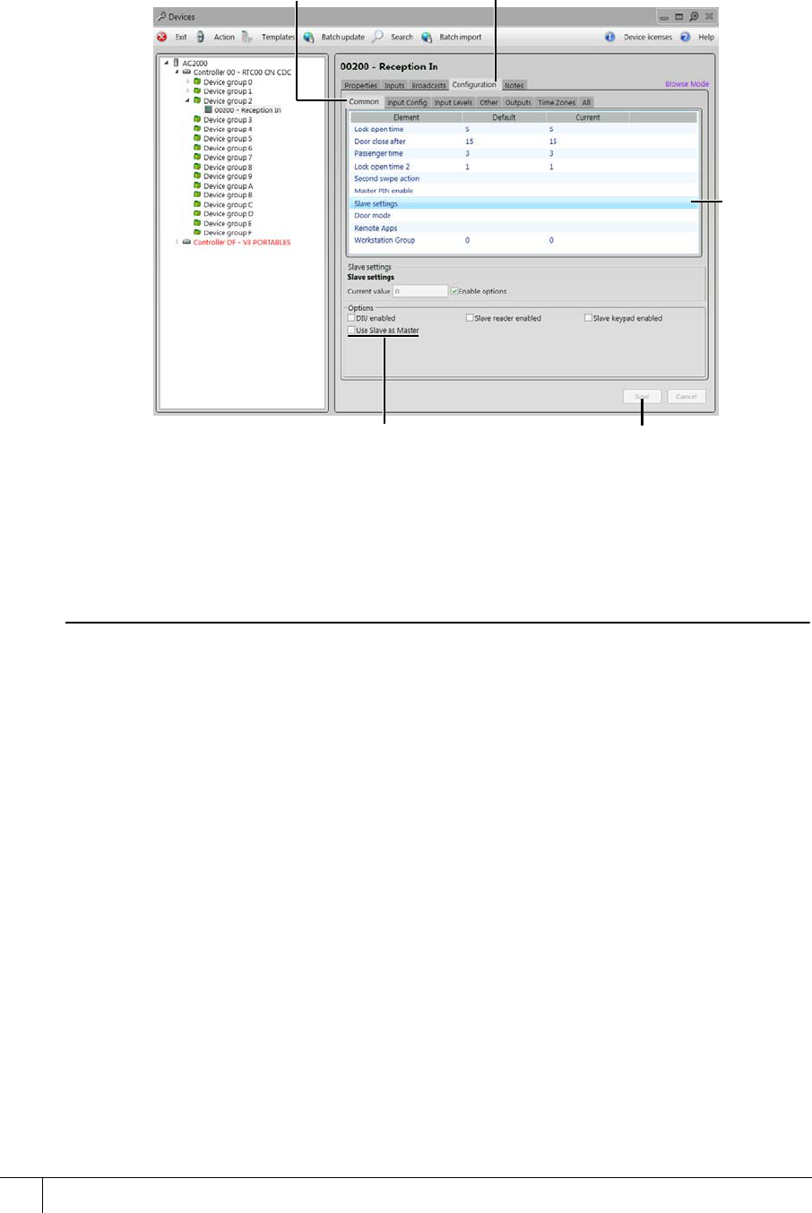
TSR-IM-0045-1.6
86
3. Once the device is added, select it from the list and open the Configuration panel.
4. Open the Common panel.
Figure 82 Setting slave as master reader
5. Select Slave settings from the panel list.
6. Check the option Use Slave as Master.
Note
If Use Slave as Master does not appear in the Options pane, please contact CEM Support to
obtain the relevant CDC patch file, which after application, will cause the Use Slave as Master
option to be displayed.
7. Click Save to save all changes made.
Configuration
panel
Common
panel
Slave
settings
Save
Use Slave
as Master
checkbox
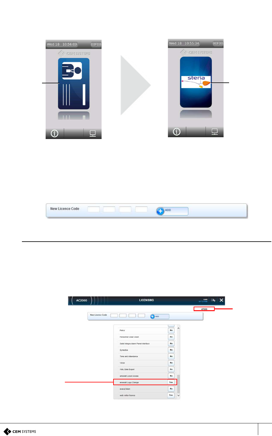
emerald TS100/200/300 Installation Manual
87
Appendix F: User Defined Logo
The Card Logo function is used to display a user defined logo on the emerald terminal. This logo
replaces the default CEM logo that appears on the dancing card on the main emerald screen.
Figure 83 Replacing existing dancing card logo with a user defined logo
To display a Card Logo on the emerald terminal, it must be uploaded using AC2000 WEB.
Licensing the emerald logo change function
1. Log into AC2000 Web.
2. Navigate to AC2000 Setup | Licensing.
Figure 84 Licensing code entry field
Note
If you do not have a license, contact CEM quoting your System ID number to receive a
emerald logo change license code.The System ID is displayed at the top right of the
Licensing application interface. (See Figure 85)
3. In the Licensing application, type the four part license code and click Add.
4. Once the license code has been applied, scroll the list of licenses to check that ‘Yes’ is
displayed beside the emerald Logo Change option.
Figure 85 emerald Logo Change license added to the CDC
Existing logo
on dancing
card
User defined
logo on
dancing card
emerald Logo
Change license
added
successfully
System ID
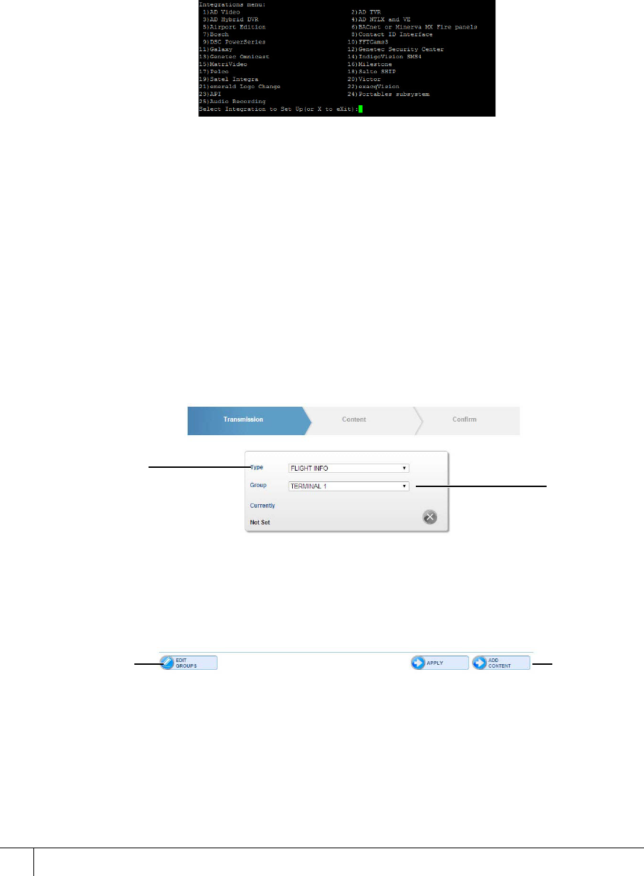
A2SE67-UG-0011-1
User Defined Logo
88
Enabling the emerald logo change function on the CDC
To enable the integration on the CDC:
5. Open an interface with the server, by either:
i. Remotely opening a SSH terminal emulator connection (such as Putty) with the CDC.
ii. Or, directly accessing the CDC console.
6. Login as user: root
7. Type I in the command line and press return to display the Integrations menu.
Figure 86 Integrations menu in a terminal emulator
8. Type the option number corresponding with emerald Logo Change (21 in the example
displayed in Figure 86) and press Return.
9. Press Return when prompted, to display the integrations menu again.
10. Type X and press Return to exit integrations menu.
11. Type L and press Return to log out of terminal emulator session.
Uploading a user defined Card Logo in AC2000 WEB
12. Log in to AC2000 WEB.
13. Select emerald Configuration | File Upload.
14. From the main File Upload page select the file Type as DISPLAY.
Figure 87 Creating a user defined logo
15. Select a Group from the list. For more information on Groups, see Creating a Group in
the AC2000 WEB manual.
File Type
Group
Edit
Groups Add
Content
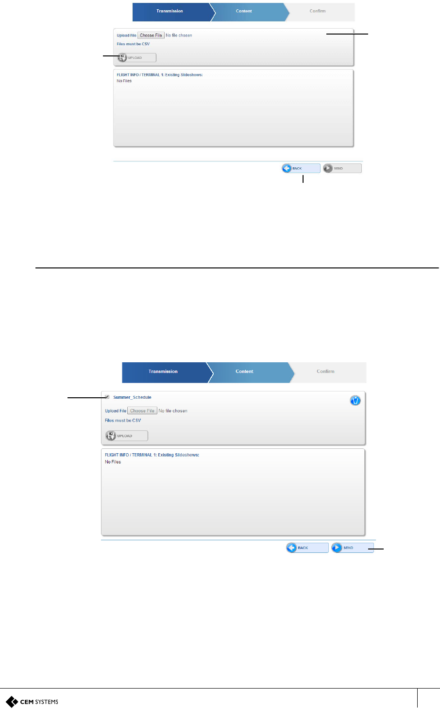
emerald TS100/200/300 Installation Manual
89
16. Click ADD CONTENT.
Figure 88 Uploading a logo
17. Click Browse.
18. Locate the required file and click Open.
Note
The image must be in PNG format. The recommended size is 287 pixels high by 143 pixels
wide and the maximum file size is 90kB.
19. Click UPLOAD.
20. Type a name for the logo in the content name field.
21. Click OK.
Figure 89 Verifying logo is uploaded
Upload
Browse to
file
Return to previous page
Logo
uploaded
successfull
Send logo

A2SE67-UG-0011-1
User Defined Logo
90
22. Click SEND.
Figure 90 Confirming logo is ready to be displayed on the emerald terminal
23. Click OK when the confirmation prompt is displayed (See Figure 90). This displays a
confirmation message that the image has been sent to all emerald readers on the system.
Note
The logo will only update on each reader, following a car swipe.
The uploaded logo will replace the existing logo on the dancing card display on the emerald
terminal. To add an additional logo, click ANOTHER.
Add additional logo

emerald TS100/200/300 Installation Manual
91

CEM Systems
195 Airport Road West
Belfast
BT3 9ED
United Kingdom
Tel: +44(0)2890 456767