Controlled Entry Distributors 300MCD21V2-CG Remote Controller User Manual
Controlled Entry Distributors, Inc. Remote Controller Users Manual
UserManual.wiki
>
Controlled Entry Distributors
>
300MCD21V2 CG User Manual
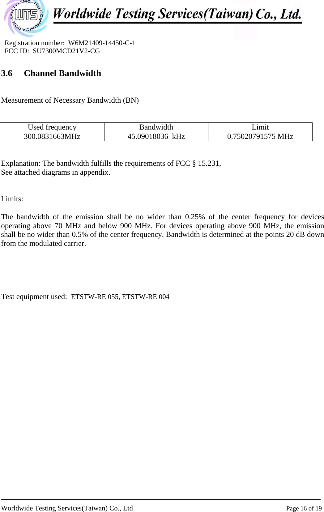
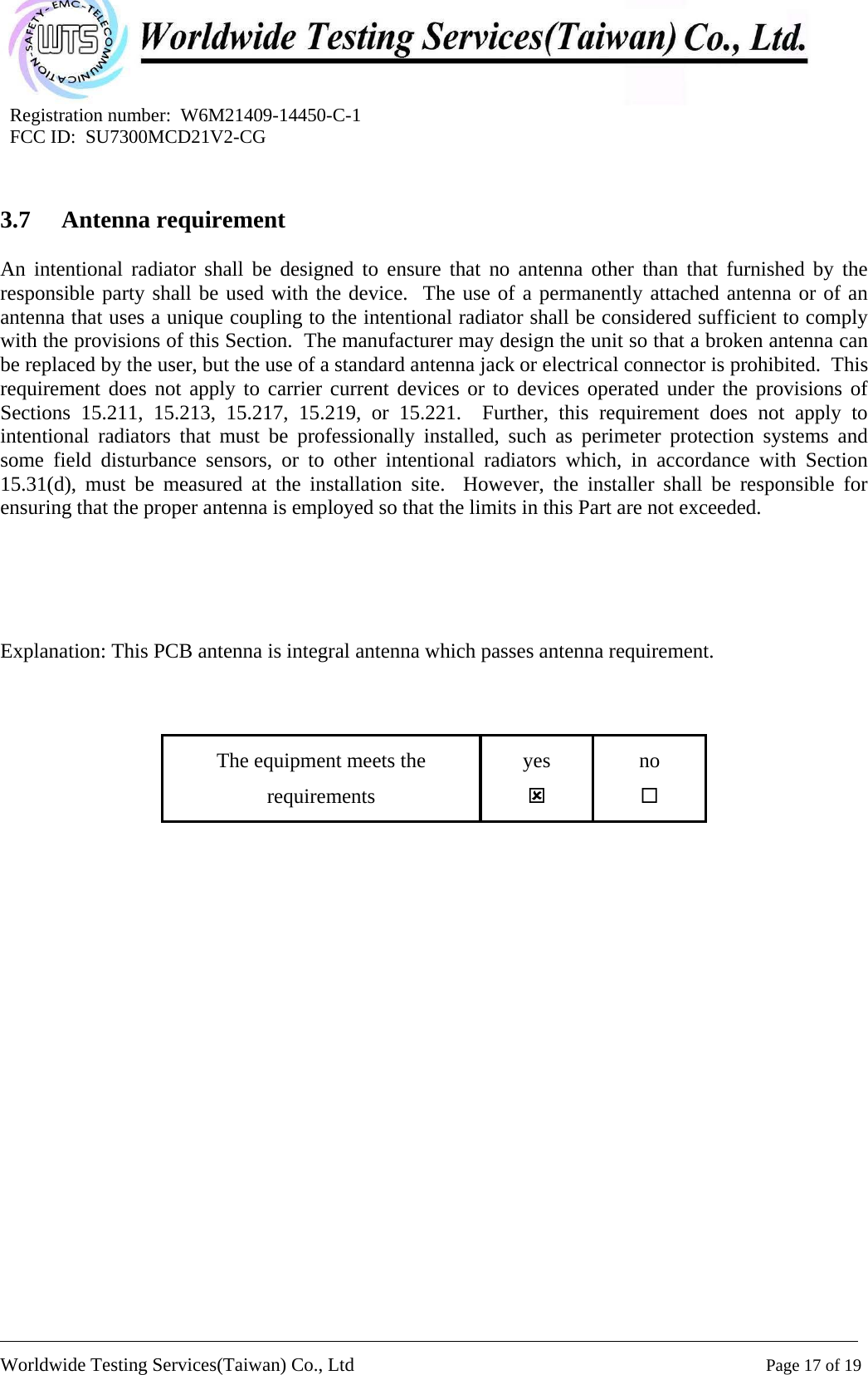
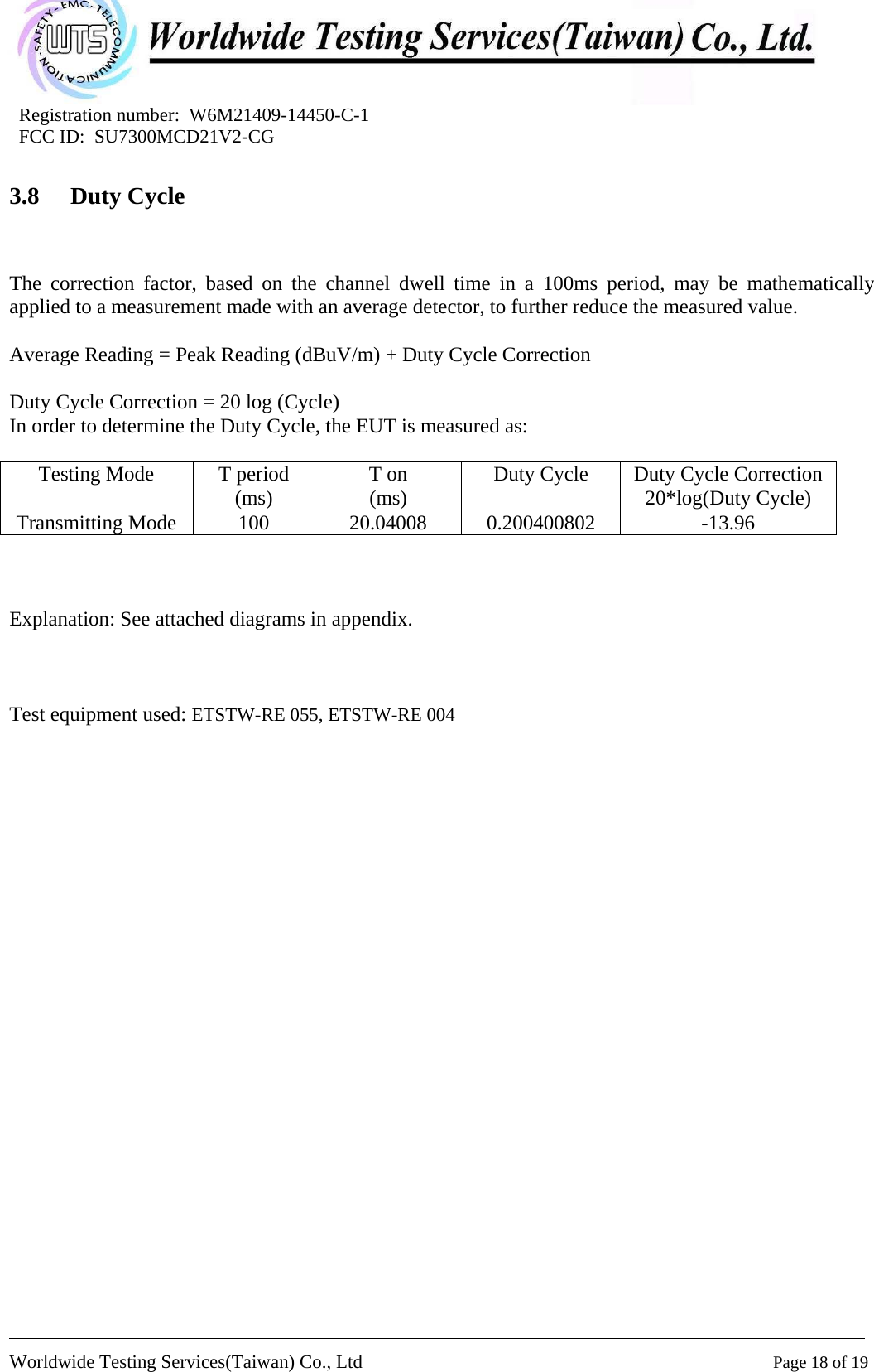
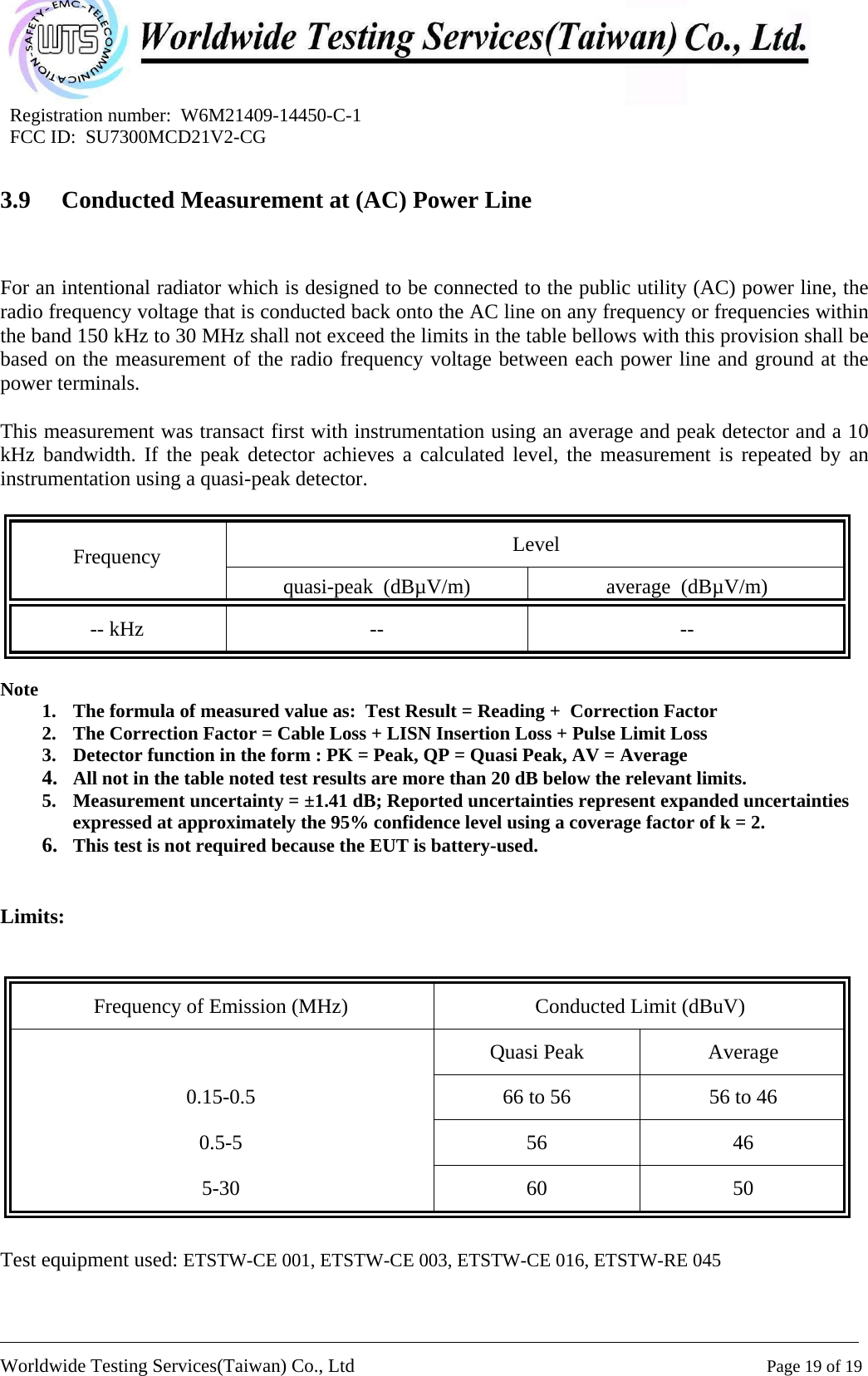
Users Manual
Navigation menu
Upload a User Manual
Namespaces
Wiki Guide
HTML
PDF
Info
Views
User Manual
Discussion / Help
Navigation