Controlled Entry Distributors 300MCD21V2-CG Remote Controller User Manual
Controlled Entry Distributors, Inc. Remote Controller Users Manual
Users Manual

of
Applicant: Controlled Entry Distributors, Inc.
Address: 2500 South 3850 West Suite A Salt Lake City Utah United States
84120
Tested and Prepared
by
Worldwide Testing Services (Taiwan) Co., Ltd.
FCC Registration No.: 930600
Industry Canada filed test laboratory Reg. No. IC 5679A-1
A2LA Accredited No.: 2732.01
Report No.: W6M21409-14450-C-1
6F, NO. 58, LANE 188, RUEY-KUANG RD., NEIHU TAIPEI 114, TAIWAN, R.O.C.
TEL: 886-2-66068877 FAX: 886-2-66068879 E-mail: wts@wts-lab.com
FCC PART 15 SUBPART C TEST REPORT
for
Remote Controller
Model No.: 300MCD21V2-C
FCC ID: SU7 300MCD21V2-CG

Registration number: W6M21409-14450-C-1
FCC ID: SU7300MCD21V2-CG
Worldwide Testing Services(Taiwan) Co., Ltd Page 1 of 19
TABLE OF CONTENTS
1 General Information........................................................................................................................2
1.1 Notes ...........................................................................................................................................2
1.2 Testing laboratory.......................................................................................................................3
1.2.1 Location ..................................................................................................................................3
1.2.2 Details of accreditation status................................................................................................3
1.3 Details of approval holder...........................................................................................................3
1.4 Application details......................................................................................................................4
1.5 Test item .....................................................................................................................................4
1.6 Test standards .............................................................................................................................5
2 Technical test..................................................................................................................................5
2.1 Summary of test results...............................................................................................................5
2.2 Test environment ........................................................................................................................5
2.3 Test equipment utilized...............................................................................................................6
2.4 General Test Procedure...............................................................................................................8
3 Test results (enclosure)...................................................................................................................9
3.1 Transmission Requirements......................................................................................................10
3.1.1 Limit of Transmission Time ..................................................................................................10
3.1.2 Active Time ...........................................................................................................................10
3.2 Output Power (Field Strength)..................................................................................................11
3.3 Out of Band Radiated Emissions..............................................................................................12
3.4 Transmitter Radiated Emissions in restricted Bands ................................................................13
3.5 Spurious Emission radiated, Transmitter..................................................................................14
3.6 Channel Bandwidth...................................................................................................................16
3.7 Antenna requirement.................................................................................................................17
3.8 Duty Cycle ................................................................................................................................18
3.9 Conducted Measurement at (AC) Power Line..........................................................................19
Appendix: Diagrams and photos

Registration number: W6M21409-14450-C-1
FCC ID: SU7300MCD21V2-CG
Worldwide Testing Services(Taiwan) Co., Ltd Page 2 of 19
1 General Information
1.1 Notes
The purpose of conformity testing is to increase the probability of adherence to the essential
requirements or conformity specifications, as appropriate.
The complexity of the technical specifications, however, means that full and thorough testing is
impractical for both technical and economic reasons.
Furthermore, there is no guarantee that a test sample which has passed all the relevant tests conforms to
a specification.
Neither is there any guarantee that such a test sample will interwork with other genuinely open systems.
The existence of the tests nevertheless provides the confidence that the test sample possesses the
qualities as maintained and that is performance generally conforms to representative cases of
communications equipment.
The test results of this test report relate exclusively to the item tested as specified in 1.5.
The test report may only be reproduced or published in full.
Reproduction or publication of extracts from the report requires the prior written approval of the
Worldwide Testing Services(Taiwan) Co., Ltd.
Tester:
September 09, 2014 Leon Chueh
Date WTS-Lab. Name Signature
Technical responsibility for area of testing:
September 09, 2014 Kevin Wang
Date WTS Name Signature

Registration number: W6M21409-14450-C-1
FCC ID: SU7300MCD21V2-CG
Worldwide Testing Services(Taiwan) Co., Ltd Page 3 of 19
1.2 Testing laboratory
1.2.1 Location
OATS
No.5-1, Lishui, Shuang Sing Village,
Wanli Dist., New Taipei City 207,
Taiwan (R.O.C.)
3 meter semi-anechoic chamber
No.35, Aly. 21, Ln. 228, Ankang Rd., Neihu Dist., Taipei City 114, Taiwan (R.O.C.)
TEL:886-2-6613-0228
FAX:886-2-2791-5046
Company
Worldwide Testing Services(Taiwan) Co., Ltd.
6F, NO. 58, LANE 188, RUEY-KUANG RD.
NEIHU, TAIPEI 114, TAIWAN R.O.C.
Tel : 886-2-66068877
Fax : 886-2-66068879
1.2.2 Details of accreditation status
Accredited testing laboratory
A2LA accredited number: 2732.01
FCC filed test laboratory Reg. No. 930600
Industry Canada filed test laboratory Reg. No. IC 5679A-1, IC 5107A
Test location, where different from Worldwide Testing Services (Taiwan) Co., Ltd. :
Name: ./.
Accredited number: ./.
Street: ./.
Town: ./.
Country: ./.
Telephone: ./.
Fax: ./.
1.3 Details of approval holder
Name : Controlled Entry Distributors, Inc.
Street : 2500 South 3850 West Suite A Salt Lake City 84120
Town : Utah
Country : United States
Telephone : 801-972-4331
Fax : 801-972-1202

Registration number: W6M21409-14450-C-1
FCC ID: SU7300MCD21V2-CG
Worldwide Testing Services(Taiwan) Co., Ltd Page 4 of 19
1.4 Application details
Date of receipt of test item: September 02, 2014
Date of test: from September 03, 2014 to September 09, 2014
1.5 Test item
Description of test item: Remote Controller
Type identification: 300MCD21V2-C
Brand name: ./.
Multi-listing model number: ./.
Transmitting frequency: 300 MHz
Operation mode: simplex
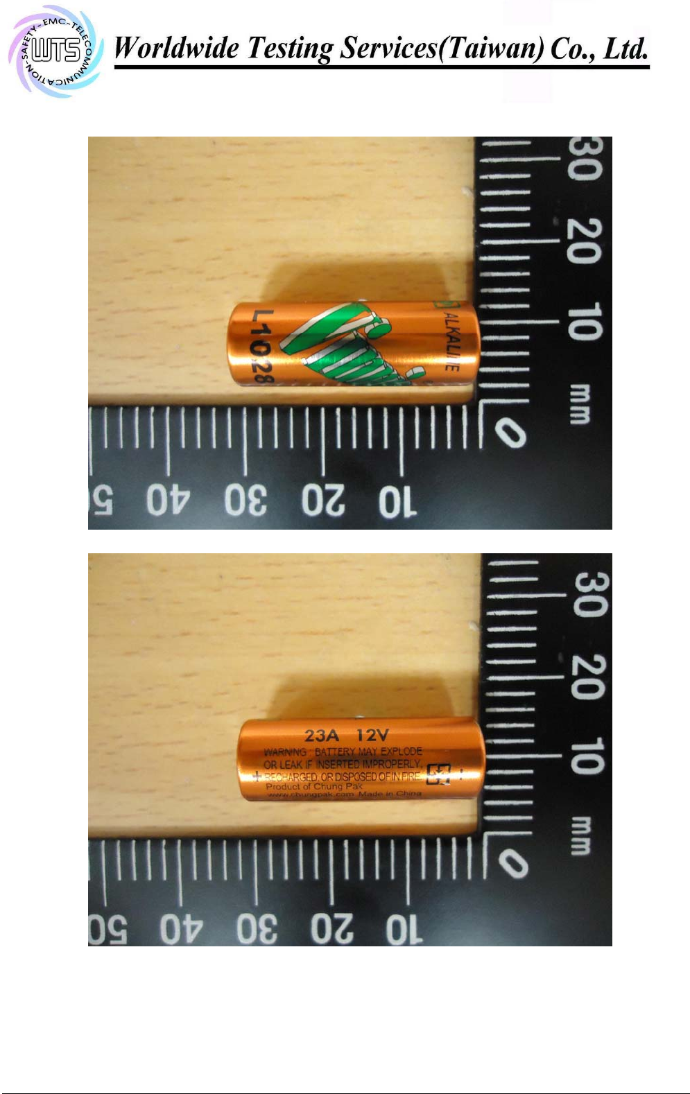
Voltage supply: Battery 12Vdc, 23A
(The device is tested under fresh battery condition.)
Highest clock frequency: 300 MHz
Antenna type: PCB Antenna
Photos: see Annex
Manufacturer (if applicable)
Name: Lighting Tech Co., Ltd.
Street: Room 1, 5F., No.530,Sec.2, Jhongshan Rd., Jhonghe City,
Town: Taipei County 235,
Country: Taiwan R.O.C.
Additional information: ./.

Registration number: W6M21409-14450-C-1
FCC ID: SU7300MCD21V2-CG
Worldwide Testing Services(Taiwan) Co., Ltd Page 5 of 19
1.6 Test standards
Technical standard : FCC RULES PART 15 SUBPART C § 15.231 (a) (2013-10)
2 Technical test
2.1 Summary of test results
No deviations from the technical specification(s) were ascertained in the course
of the tests performed.
or
The deviations as specified in 3 were ascertained in the course of the tests
performed.
2.2 Test environment
Temperature: 23
oC
Relative humidity content: 20 ... 75 %
Air pressure: 86 ... 103 kPa
Details of power supply: Battery 12Vdc, 23A

Registration number: W6M21409-14450-C-1
FCC ID: SU7300MCD21V2-CG
Worldwide Testing Services(Taiwan) Co., Ltd Page 6 of 19
2.3 Test equipment utilized
No. Test equipment Type Serial No. Manufacturer Cal. Date Next Cal.
Date
ETSTW-CE 001 EMI TEST RECEIVER ESHS10 842121/013 R&S 2014/9/3 2015/9/2
ETSTW-CE 003 AC POWER SOURCE APS-9102 D161137 GW Function Test
ETSTW-CE 008 HF-EICHLEITUNG RF
STEP ATTENUATOR
139dB DPSP 334.6010.02 844581/024 R&S Function Test
ETSTW-CE 009 TEMP.&HUMIDITY
CHAMBER GTH-225-40-1P-U MAA0305-009 GIANT FORCE 2014/7/8 2015/7/7
ETSTW-CE 016 TWO-LINE V-NETWORK ENV216 100050 R&S 2013/10/28 2014/10/27
ETSTW-RE 004 EMI TEST RECEIVER ESI 40 832427/004 R&S 2014/9/3 2015/9/2
ETSTW-RE 005 EMI TEST RECEIVER ESVS10 843207/020 R&S 2014/9/3 2015/9/2
ETSTW-RE 012 TUNABLE BANDREJECT
FILTER D.C 0309 146 K&L Function Test
ETSTW-RE 013 TUNABLE BANDREJECT
FILTER D.C 0336 397 K&L Function Test
ETSTW-RE 018 MICROWAVE HORN
ANTENNA AT4560 27212 AR 2013/10/15 2014/10/14
ETSTW-RE 027 Passive Loop Antenna 6512 00034563 ETS-Lindgren 2014/7/01 2015/6/30
ETSTW-RE 030 Double-Ridged Guide Horn
Antenna 3117 00035224 EMCO 2014/2/25 2015/2/24
ETSTW-RE 045 ESA-E SERIES
SPECTRUM ANALYZER E4404B MY45111242 Agilent Pre-test Use
ETSTW-RE 049 TRILOG Super Broadband
test Antenna VULB 9160 9160-3185 Schwarzbeck 2014/2/18 2015/2/17
ETSTW-RE 050 Attenuator 10dB 50HF-010-1 None JFW 2014/3/3 2015/3/2
ETSTW-RE 051 Attenuator 6dB 50HF-006-1 None JFW 2014/3/3 2015/3/2
ETSTW-RE 053 Attenuator 3dB 50HF-003-1 None JFW 2014/3/3 2015/3/2
ETSTW-RE 055 SPECTRUM ANALYZER FSU 26 200074 R&S 2014/6/05 2015/6/04
ETSTW-RE 060 Attenuator 30dB 5015-30 F651012z-01 ATM 2014/3/3 2015/3/2
ETSTW-RE 062 Amplifier Module CHC 2 None KMIC 2013/11/27 2014/11/26
ETSTW-RE 064 Bluetooth Test Set MT8852B-042 6K00005709 Anritsu Function Test
ETSTW-RE 069 Double-Ridged Guide Horn
Antenna 3117 00069377 EMCO Function Test
ETSTW-RE 072 CELL SITE TEST SET 8921A 3339A00375 HP 2013/10/7 2014/10/6
ETSTW-RE 088 SOLID STATE
AMPLIFIER KMA180265A01 99057 KMIC 2013/10/11 2014/10/10
ETSTW-RE 099 DC Block 50DB-007-1 None JFW 2014/3/3 2015/3/2
ETSTW-RE 106 Humidity Temperature
Meter TES-1366 091011113 TES 2013/12/04 2014/12/03
ETSTW-RE 111 TRILOG Super Broadband
test Antenna VULB 9160 9160-3309 Schwarz beck 2013/12/27 2014/12/26
ETSTW-RE 112 AC POWER SOURCE TFC-1005 None T-Power Function test
ETSTW-RE 115 2.4GHz Notch Filter N0124411 473874 MICROWAVE
CIRCUITS 2014/1/10 2015/1/09
ETSTW-RE 120 RF Player MP9200 MP9210-111022 ADIVIC Function test
ETSTW-RE 122 SIGNAL GENERATOR SMF100A 102149 R&S 2014/6/11 2015/6/10
ETSTW-RE 125 5GHz Notch filter 5NSL11-
5200/E221.3-O/O 1 K&L Microwave 2014/8/12 2015/8/11
Registration number: W6M21409-14450-C-1
FCC ID: SU7300MCD21V2-CG
Worldwide Testing Services(Taiwan) Co., Ltd Page 7 of 19
ETSTW-RE 126 5GHz Notch filter 5NSL11-
5800/E221.3-O/O 1 K&L Microwave 2014/8/12 2015/8/11
ETSTW-RE 127 RF Switch Box RFS-01 None WTS 2014/3/3 2015/3/2
ETSTW-RE 128 5.3GHz Notch filter N0153001 SN487233 Microwave Circits 2014/8/12 2015/8/11
ETSTW-RE 129 5.5GHz Notch filter N0555984 SN487234 Microwave Circits 2014/8/12 2015/8/11
ETSTW-RE 130 Handheld RF Spectrum
Analyzer N9340A CN0147000204 Agilent Pre-test Use
ETSTW-GSM 002 Universal Radio
Communication Tester CMU 200 109439 R&S 2013/10/7 2014/10/6
ETSTW-GSM 019 Band Reject Filter WRCTF824/849-
822/851-40 /12+9SS 3 WI 2014/1/10 2015/1/09
ETSTW-GSM 020 Band Reject Filter WRCD1747/1748-
1743/1752-32/5SS 1 WI 2014/1/10 2015/1/09
ETSTW-GSM 021 Band Reject Filter WRCD1879.5/1880.5
-1875.5/1884.5-
32/5SS 3 WI 2014/1/10 2015/1/09
ETSTW-GSM 022 Band Reject Filter WRCT901.9/903.1-
904.25-50/8SS 1 WI 2014/1/10 2015/1/09
ETSTW-GSM 023 Power Divider 4901.19.A None SUHNER 2014/9/3 2015/9/2
ETSTW-Cable 010 BNC Cable 5 M BNC Cable None JYE BAO CO.,LTD. 2014/2/27 2015/2/26
ETSTW-Cable 011 BNC Cable BNC Cable 1 None JYE BAO CO.,LTD. Pre-test Use NCR
ETSTW-Cable 012 N TYPE To SMA Cable Cable 012 None JYE BAO CO.,LTD. 2014/2/27 2015/2/26
ETSTW-Cable 016 BNC Cable Switch Box B Cable 1 Schwarz beck 2014/2/27 2015/2/26
ETSTW-Cable 017 BNC Cable X Cable B Cable 2 Schwarz beck 2014/2/27 2015/2/26
ETSTW-Cable 018 BNC Cable Y Cable B Cable 3 Schwarz beck 2014/2/27 2015/2/26
ETSTW-Cable 019 BNC Cable Z Cable B Cable 4 Schwarz beck 2014/2/27 2015/2/26
ETSTW-Cable 022 N TYPE Cable 5006 0002 JYE BAO CO.,LTD. 2014/2/19 2015/2/18
ETSTW-Cable 026 Microwave Cable SUCOFLEX 104 279075 HUBER+SUHNER 2014/3/3 2015/3/2
ETSTW-Cable 027 Microwave Cable SUCOFLEX 104 279083 HUBER+SUHNER 2014/3/3 2015/3/2
ETSTW-Cable 028 Microwave Cable FA147A0015M2020 30064-2 UTIFLEX 2013/10/11 2014/10/10
ETSTW-Cable 029 Microwave Cable FA147A0015M2020 30064-3 UTIFLEX 2013/10/11 2014/10/10
ETSTW-Cable 030 Microwave Cable SUCOFLEX 104
(S_Cable 9) 279067 HUBER+SUHNER 2014/3/3 2015/3/2
ETSTW-Cable 031 Microwave Cable SUCOFLEX 104
(S_Cable 10) 238092 HUBER+SUHNER
2013/11/27 2014/11/26
ETSTW-Cable 043 Microwave Cable SUCOFLEX 104 317576 HUBER+SUHNER 2013/11/27 2014/11/26
ETSTW-Cable 047 Microwave Cable SUCOFLEX 104 325518 HUBER+SUHNER 2013/11/27 2014/11/26
ETSTW-Cable 053 N TYPE To SMA Cable RG142 None JYE BAO CO.,LTD. 2014/2/19 2015/2/18
ETSTW-Cable 058 Microwave Cable SUCOFLEX 104 none HUBER+SUHNER 2014/2/19 2015/2/18
WTSTW-SW 002 EMI TEST SOFTWARE EZ_EMC None Farad Version ETS-03A1

Registration number: W6M21409-14450-C-1
FCC ID: SU7300MCD21V2-CG
Worldwide Testing Services(Taiwan) Co., Ltd Page 8 of 19
2.4 General Test Procedure
POWER LINE CONDUCTED INTERFERENCE: The procedure used was ANSI STANDARD C63.4-
2009 5.2 using a 50µH LISN (if necessary). Both lines were observed. The bandwidth of the spectrum
analyzer was 10 kHz with an appropriate sweep speed.
RADIATION INTERFERENCE: The test procedure used was ANSI STANDARD C63.4-2009 6.4
using a spectrum analyzer. The bandwidth of the spectrum analyzer was 100 kHz with an appropriate
sweep speed. The analyzer was calibrated in dB above a microvolt at the output of the antenna. The
resolution bandwidth was the 100 kHz and the video bandwidth was 300 kHz.
FORMULA OF CONVERSION FACTORS: The Field Strength at 3m was established by adding the
meter reading of the spectrum analyzer (which is set to read in units of dBµV) to the antenna correction
factor supplied by the antenna manufacturer. The antenna correction factors are stated in terms of dB.
Example:
Freq (MHz) METER READING + ACF + CABLE LOSS (to the receiver) = FS
33 20 dBµV + 10.36 dB/m + 6 dB = 36.36 dBµV/m @3m
ANSI STANDARD C63.4-2009 6.3.1 MEASUREMENT PROCEDURES: The EUT was placed on a
table 80 cm high and with dimensions of 1m by 1.5m (non metallic table). The EUT was placed in the
center of the table. The table used for radiated measurements is capable of continuous rotation. The
spectrum was scanned from 30 MHz to 10th harmonic of the fundamental.
Peak readings were taken in three (3) orthogonal planes and the highest readings.
Measurements were made by Worldwide Testing Services(Taiwan) Co., Ltd. at the registered open field
test site located at. The Registration Number: 930600
When an emission was found, the table was rotated to produce the maximum signal strength. At this
point, the antenna was raised and lowered from 1m to 4m. The antenna was placed in both the
horizontal and vertical planes.
ANSI STANDARD C63.4-2009 10.2.7: Any measurements that utilize special test software shall be
indicated and referenced in the test report. During testing, test software ’EZ EMC’ was used for setting
up different operation modes.
Registration number: W6M21409-14450-C-1
FCC ID: SU7300MCD21V2-CG
Worldwide Testing Services(Taiwan) Co., Ltd Page 9 of 19
3 Test results (enclosure)
1st test test after modification production test
TEST CASE Para. Number Required Test
passed Test
failed
Transmission Requirements FCC 15.231(a)
Radiated Emission FCC 15.231(b)
Bandwidth of Emission FCC 15.231(c)
Frequency Tolerance FCC 15.231(d)
Period Alternate Field Strength Requirements FCC 15.231(e)
Antenna Requirement FCC 15.203
Conducted Measurement at (AC) Power Line FCC 15.207
The following is intentionally left blank.

Registration number: W6M21409-14450-C-1
FCC ID: SU7300MCD21V2-CG
Worldwide Testing Services(Taiwan) Co., Ltd Page 10 of 19
3.1 Transmission Requirements
FCC 15.231(a)
3.1.1 Limit of Transmission Time
⌧ According to 15.231(a)(1), a manually operated transmitter shall employ a switch that will automatically
deactivate the transmitter within not more than 5 seconds of being released.
According to 15.231(a)(2), a transmitter activated automatically shall cease transmission within 5 seconds
after activation.
According to 15.231(a)(3), periodic transmissions at regular predetermined intervals are not permitted.
However, polling or supervision transmissions, including data, to determine system integrity of
transmitters used in security or safety applications are allowed if the total duration of transmissions does
not exceed more than two seconds per hour for each transmitter. There is no limit on the number of
individual transmissions, provided the total transmission time does not exceed two seconds per hour.
According to 15.231(a)(4), intentional radiators which are employed for radio control purposes during
emergencies involving fire, security, and safety of life, when activated to signal an alarm, may operate
during the pendency of the alarm condition.
According to 15.231(a)(5), transmission of set-up information for security systems may exceed the
transmission duration limits in paragraphs (a)(1) and (a)(2) of this section, provided such transmission
are under the control of a professional installer and do not exceed ten seconds after a manually operated
switch is released or a transmitter is activated automatically. Such set-up information may include data.
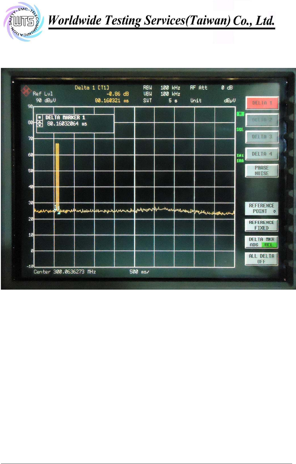
3.1.2 Active Time
⌧ This manually operated transmitter employs a switch that automatically deactivate the transmitter within
_80.16032064 ms of being released.
This transmitter is operated by automatic activation and active will cease transmission in _____ ms after
activation.
Others: This product is employed for radio control purpose during emergencies. When emergency switch is
pulled down, the EUT will transmit a signal around _____ ms and continue to retransmit the signal every 5
minutes during the pendency of the alarm condition.
Explanation: See attached diagrams in appendix.
Test equipment used: ETSTW-RE 055, ETSTW-RE 004
Registration number: W6M21409-14450-C-1
FCC ID: SU7300MCD21V2-CG
Worldwide Testing Services(Taiwan) Co., Ltd Page 11 of 19
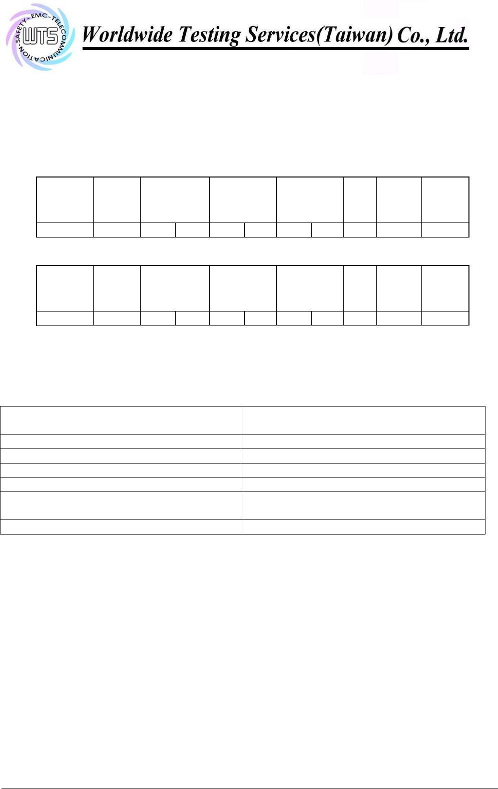
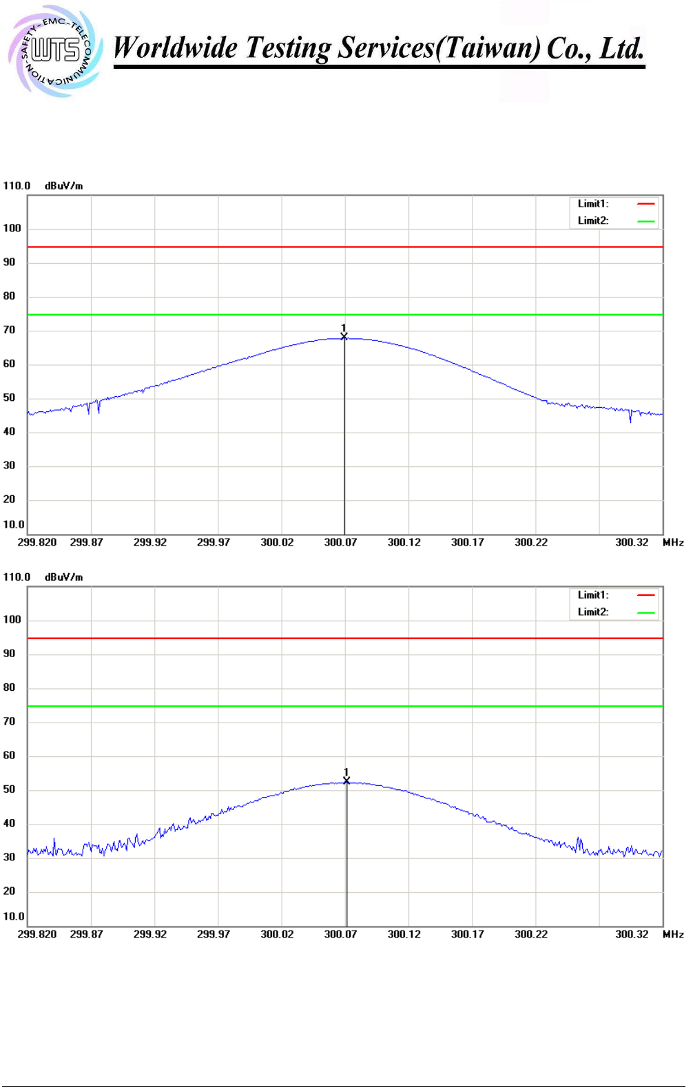
3.2 Output Power (Field Strength)
Model: 300MCD21V2-C Date: 2014/9/5
Mode: TX Temperature:
24
°C Engineer:
Leon
Polarization:
Horizontal
Humidity: 60
%
Frequency
(MHz)
Reading
(dBuV)
Peak
Factor
(dB)
Corr. Duty
Result @3m
(dBuV/m)
Peak Ave.
Limit @3m
(dBuV/m)
Peak Ave.
Margin
(dB)
Table
Degree
(Deg.)
Ant. High
(cm)
300.0691 51.79 15.99 -13.96
67.78
53.82
94.67
74.67
-20.85 260 100
Polarization:
Vertical
Frequency
(MHz)
Reading
(dBuV)
Peak
Factor
(dB)
Corr. Duty
Result @3m
(dBuV/m)
Peak Ave.
Limit @3m
(dBuV/m)
Peak Ave.
Margin
(dB)
Table
Degree
(Deg.)
Ant. High
(cm)
300.0711 36.31 15.99 -13.96
52.30
38.34
94.67
74.67
-36.33 190 100
Limit 15.231(b)
Fundamental Frequency
(MHz) Field strength of fundamental, limit
µV/m
40.66 – 40.70 2,250
70 – 130 1,250
130 – 174 1,250 to 3,750
174 – 260 3,750
260 – 470 3,750 to 12,500**
(300 MHz: 74.67 dBµV/m = 5416.677 µV/m)
Above 470 12,500
** linear interpolation
Explanation: See attached diagrams in appendix.
Test equipment used: ETSTW-RE 004, ETSTW-RE 111

Registration number: W6M21409-14450-C-1
FCC ID: SU7300MCD21V2-CG
Worldwide Testing Services(Taiwan) Co., Ltd Page 12 of 19
3.3 Out of Band Radiated Emissions
FCC Rule: 15.231(b) , 15.35
For out of band emissions that are close to or that exceed the 20 dB attenuation requirement
described in the specification, radiated measurements were performed at a 3 m separation distance
to determine whether these emissions complied with the general radiated emission requirement.
Guidance on Measurement of pulsed emission: 15.35(c)
“the measurement field strength shall be determined by averaging over one complete pulse train,
including blanking intervals, as long as the pulse train does not exceed 0.1 seconds. As an alternative
(provided the transmitter operates for longer than 0.1 seconds) or in cases where the pulse train exceeds
0.1 seconds, the measured field strength shall be determined from the average absolute voltage during a
0.1 second interval during which the field strength is at its maximum value.”
Duty Cycle correction = 20 log (dwell time/100ms or one period)
Limits:
For frequencies (Average measurements)
Correction factor conform 15.35 (c) (Average measurements)
Duty cycle correction :
Max. Peak reading – duty cycle correction
Max permitted average Limits = Max permitted Fundamental limit – 20 dB
For example for 300 fundamental carrier:
Max permitted average Limit: 74.67 dBµV/m - 20 dB= 54.67 dBµV/m
For frequencies above 1GHz (Peak measurements).
Modified Limits for peak conform 15.35 (b) = Max Permitted average Limits + 20dB (because Peak
detector is used)
Explanation: See attached diagrams in appendix.
Test equipment used: ETSTW-RE 004, ETSTW-RE 030, ETSTW-RE 111,

Registration number: W6M21409-14450-C-1
FCC ID: SU7300MCD21V2-CG
Worldwide Testing Services(Taiwan) Co., Ltd Page 13 of 19
3.4 Transmitter Radiated Emissions in restricted Bands
FCC Rules: 15.231 (b), 15.205, 15.209, 15.35
Radiated emission measurements were performed from 30 MHz to 8000 MHz.
For radiated emission tests, the analyzer setting was as followings:
RES BW VID BW
Frequency <1 GHz 100 kHz 100 kHz (Peak measurements)
Frequency >1 GHz 1 MHz 1 MHz (Peak measurements)
1 MHz 1 MHz (Average measurements)
Limits:
For frequencies below 1GHz :
Frequency of Emission
(MHz) Field strength
(microvolts/meter) Field Strength
(dB microvolts/meter)
30 – 88 100 40.0
88 – 216 150 43.5
216 – 960 200 46.0
Above 960 500 54.0
For frequencies above 1GHz (Average measurements).
Guidance on Measurement of pulsed emission:
“If the emission is pulsed, modify the unit for continues operation , use the settings shown above,
then correct the reading by subtracting the peak-average correction factor, derived from the
appropriate duty cycle calculation.
For frequencies above 1GHz (Average measurements).
The correction factor, based on the channel dwell tine in a 100 ms period, may be mathematically
applied to a measurement made with an average detector, to further reduce the value.
Duty cycle correction = 20 log (dwell time/100ms)
No duty cycle correction was added to the reading
Modified Limits for peak conform 15.35 (b) = Max Permitted average Limits + 20dB (because Peak
detector is used)
Above 960 MHz
For mode DSSS CW: 54 dBµV/m + 20 dB = 74 dBµV/m
Explanation: See attached diagrams in appendix.
Registration number: W6M21409-14450-C-1
FCC ID: SU7300MCD21V2-CG
Worldwide Testing Services(Taiwan) Co., Ltd Page 14 of 19
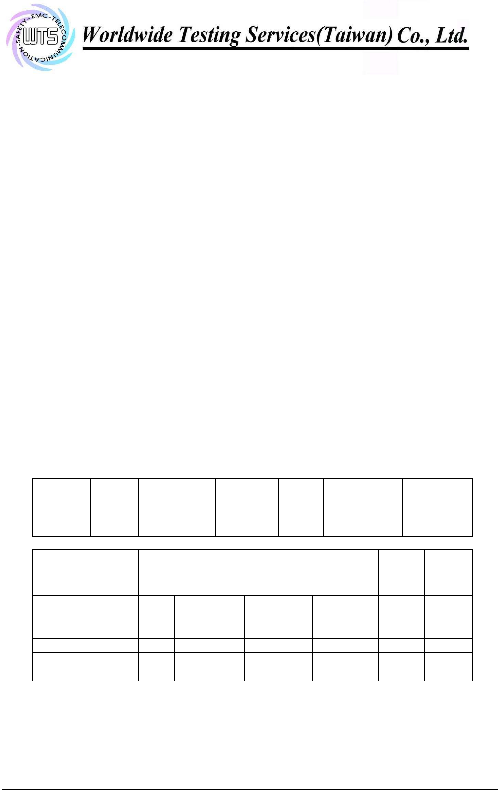
3.5 Spurious Emission radiated, Transmitter
Spurious emission was measured with modulation (declared by manufacturer).
The limits on the field strength of the spurious emission in the table § 15.231(b) are based on the
fundamental frequency of the intentional radiator. Spurious emission shall be attenuated to the average
(or alternatively, CISPR quasi-peak) limits shown in this table or to the general limits shown in §
15.209, whichever limit permits a higher field strength.
In addition, radiated emission which fall in the restricted bands, as defined in § 15.205(a), must also
comply with the radiated emission limits specified in § 15.209(a) (See § 15.205(c)).
SAMPLE CALCULATION OF LIMIT. All results will be updated by an automatic measuring system
in accordance to point 2.3.
Calculation of test results:
Such factors like antenna correction, cable loss, external attenuation etc. are already included in the
provided measurement results. This is done by using validated test software and calibrated test system
according the accreditation requirements.
The peak and average spurious emission plots was measured with the average limits.
In the Table being listed the critical peak and average value an exhibit the compliance with the above
calculated Limits.
Summary table with radiated data of the test plots
Model: 300MCD21V2-C Date: 2014/9/5
Mode: 300MHz Temperature:
24
°C Engineer: Leon
Polarization: Horizontal Humidity: 60
%
Frequency
(MHz) Reading
(dBuV)
Detector
Factor
(dB)
Result
(dBuV/m) Limit
(
dBuV/m
)
Margin
(dB)
Table
Degree
(Deg.)
Ant.
High
(cm)
130.1002 3.38 peak 14.16
17.54 43.50 -25.96
135 100
Frequency
(MHz)
Reading
(dBuV)
Peak
Factor
(dB)
Corr. Duty
Result @3m
(dBuV/m)
Peak Ave.
Limit @3m
(dBuV/m)
Peak Ave.
Margin
(dB)
Table
Degree
(Deg.)
Ant. High
(cm)
600.2002 29.33 23.20 -13.96
52.53
38.57
74.67
54.67
-16.10 210 100
900.4008 34.75 27.15 -13.96
61.90
47.94
74.67
54.67
-6.73 195 100
1200.4010 65.99 -9.52 -13.96
56.47
42.51
74.00
54.00
-11.49 235 100
1501.0020 52.71 -9.04 -13.96
43.67
29.71
74.00
54.00
-24.29 90 100
1800.0000 44.37 -7.01 -13.96
37.36
23.40
74.67
54.94
-31.54 110 100
2100.2000 45.22 -5.77 -13.96
39.45
25.49
74.67
54.94
-29.45 125 100
Registration number: W6M21409-14450-C-1
FCC ID: SU7300MCD21V2-CG
Worldwide Testing Services(Taiwan) Co., Ltd Page 15 of 19
Polarization: Vertical
Frequency
(MHz) Reading
(dBuV)
Detector
Factor
(dB) Result
(dBuV/m) Limit
(
dBuV/m
)
Margin
(dB)
Table
Degree
(Deg.)
Ant.
High
(cm)
114.9498 2.27 peak 12.81
15.08 43.50 -28.42
40 100
Frequency
(MHz)
Reading
(dBuV)
Peak
Factor
(dB)
Corr. Duty
Result @3m
(dBuV/m)
Peak Ave.
Limit @3m
(dBuV/m)
Peak Ave.
Margin
(dB)
Table
Degree
(Deg.)
Ant. High
(cm)
600.2003 24.67 23.20 -13.96
47.87
33.91
74.67
54.67
-20.76 145 100
900.4008 21.55 27.15 -13.96
48.70
34.74
74.67
54.67
-19.93 190 100
1200.4010 52.07 -9.52 -13.96
42.55
28.59
74.00
54.00
-25.41 210 100
1500.0000 44.49 -9.05 -13.96
35.44
21.48
74.00
54.00
-32.52 145 100
1800.0000 43.98 -7.01 -13.96
36.97
23.01
74.67
54.94
-31.93 80 100
2100.0000 43.61 -5.77 -13.96
37.84
23.88
74.67
54.94
-31.06 30 100
Note 1. Correction Factor = Antenna factor + Cable loss - Preamplifier
2. The formula of measured value as: Test Result = Reading + Correction Factor
3. Detector function in the form : PK = Peak, QP = Quasi Peak, AV = Average
4. All not in the table noted test results are more than 20 dB below the relevant limits.
5. Measurement uncertainty for 3m measurement: 30-1000 MHz = ± 3.68 dB, 1-18 GHz = ± 5.37
dB, 18-40 GHz= ± 3.43 dB ; Reported uncertainties represent expanded uncertainties expressed
at approximately the 95% confidence level using a coverage factor of k = 2.
6. See attached diagrams in appendix.
All other not noted test plots do not contain significant test results in relation to the limits
Test results: The unit meet the FCC requirements.
Test equipment used: ETSTW-RE 004, ETSTW-RE 030, ETSTW-RE 111

Registration number: W6M21409-14450-C-1
FCC ID: SU7300MCD21V2-CG
Worldwide Testing Services(Taiwan) Co., Ltd Page 16 of 19
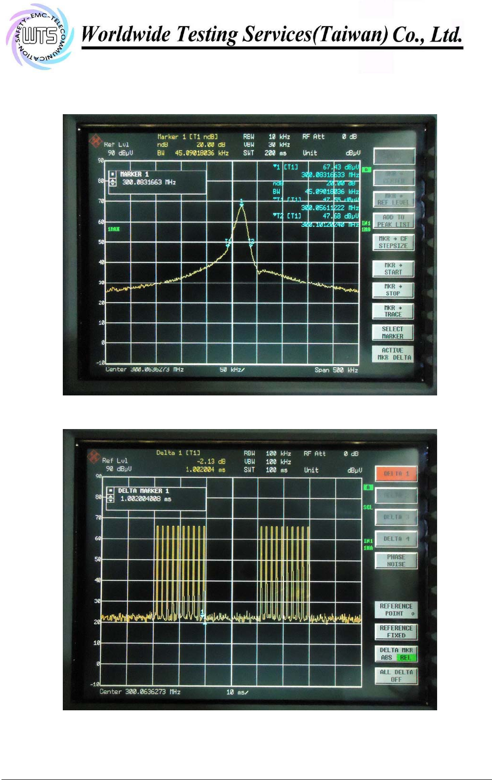
3.6 Channel Bandwidth
Measurement of Necessary Bandwidth (BN)
Used frequency Bandwidth Limit
300.0831663MHz 45.09018036 kHz 0.75020791575 MHz
Explanation: The bandwidth fulfills the requirements of FCC § 15.231,
See attached diagrams in appendix.
Limits:
The bandwidth of the emission shall be no wider than 0.25% of the center frequency for devices
operating above 70 MHz and below 900 MHz. For devices operating above 900 MHz, the emission
shall be no wider than 0.5% of the center frequency. Bandwidth is determined at the points 20 dB down
from the modulated carrier.
Test equipment used: ETSTW-RE 055, ETSTW-RE 004

Registration number: W6M21409-14450-C-1
FCC ID: SU7300MCD21V2-CG
Worldwide Testing Services(Taiwan) Co., Ltd Page 17 of 19
3.7 Antenna requirement
An intentional radiator shall be designed to ensure that no antenna other than that furnished by the
responsible party shall be used with the device. The use of a permanently attached antenna or of an
antenna that uses a unique coupling to the intentional radiator shall be considered sufficient to comply
with the provisions of this Section. The manufacturer may design the unit so that a broken antenna can
be replaced by the user, but the use of a standard antenna jack or electrical connector is prohibited. This
requirement does not apply to carrier current devices or to devices operated under the provisions of
Sections 15.211, 15.213, 15.217, 15.219, or 15.221. Further, this requirement does not apply to
intentional radiators that must be professionally installed, such as perimeter protection systems and
some field disturbance sensors, or to other intentional radiators which, in accordance with Section
15.31(d), must be measured at the installation site. However, the installer shall be responsible for
ensuring that the proper antenna is employed so that the limits in this Part are not exceeded.
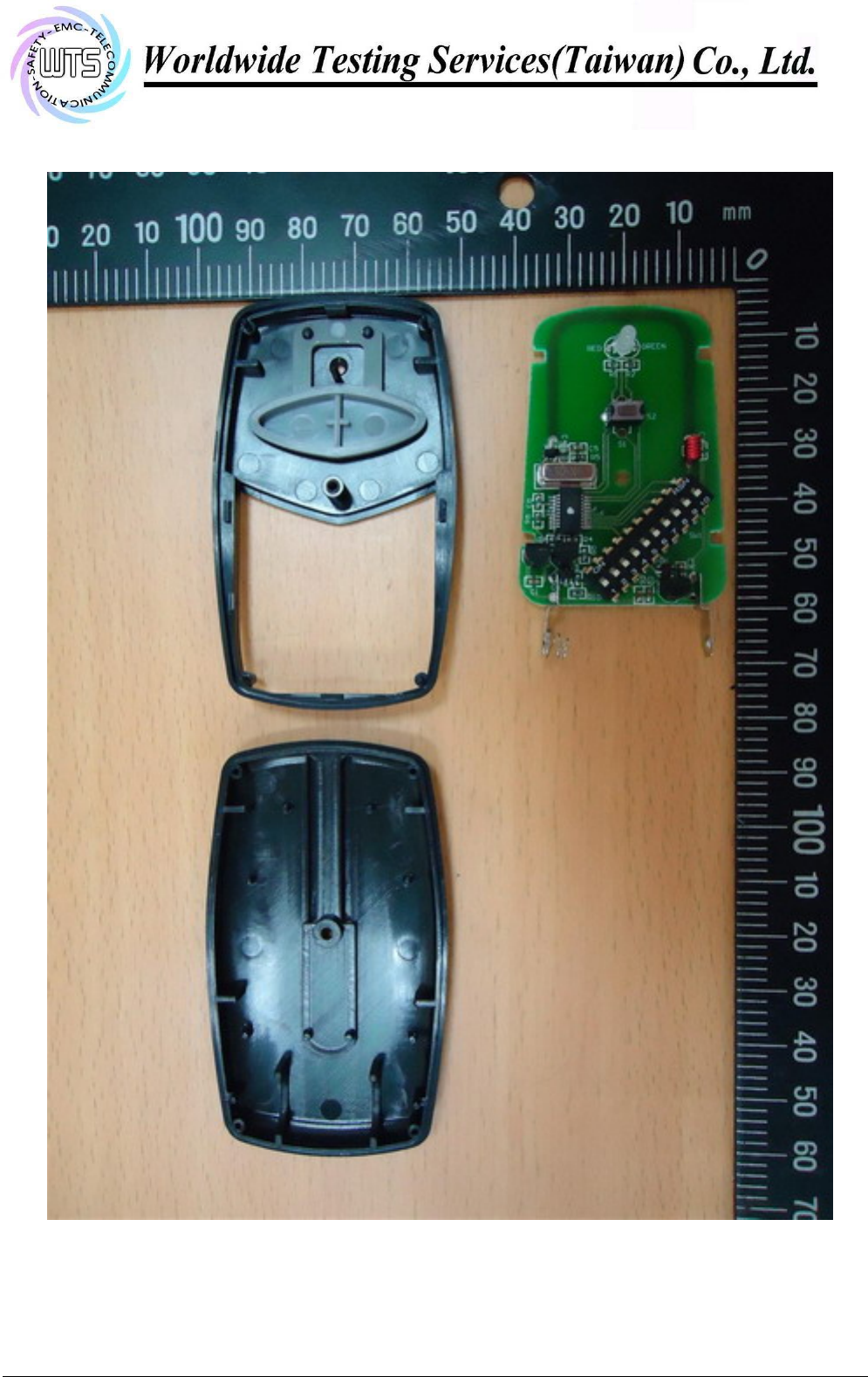
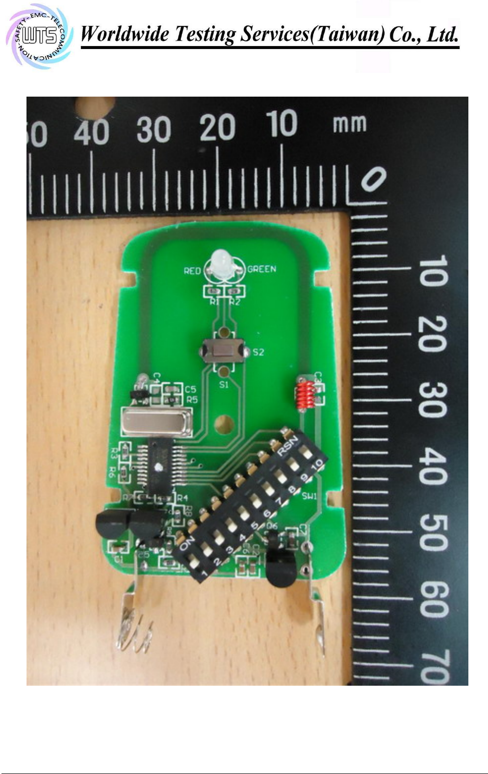
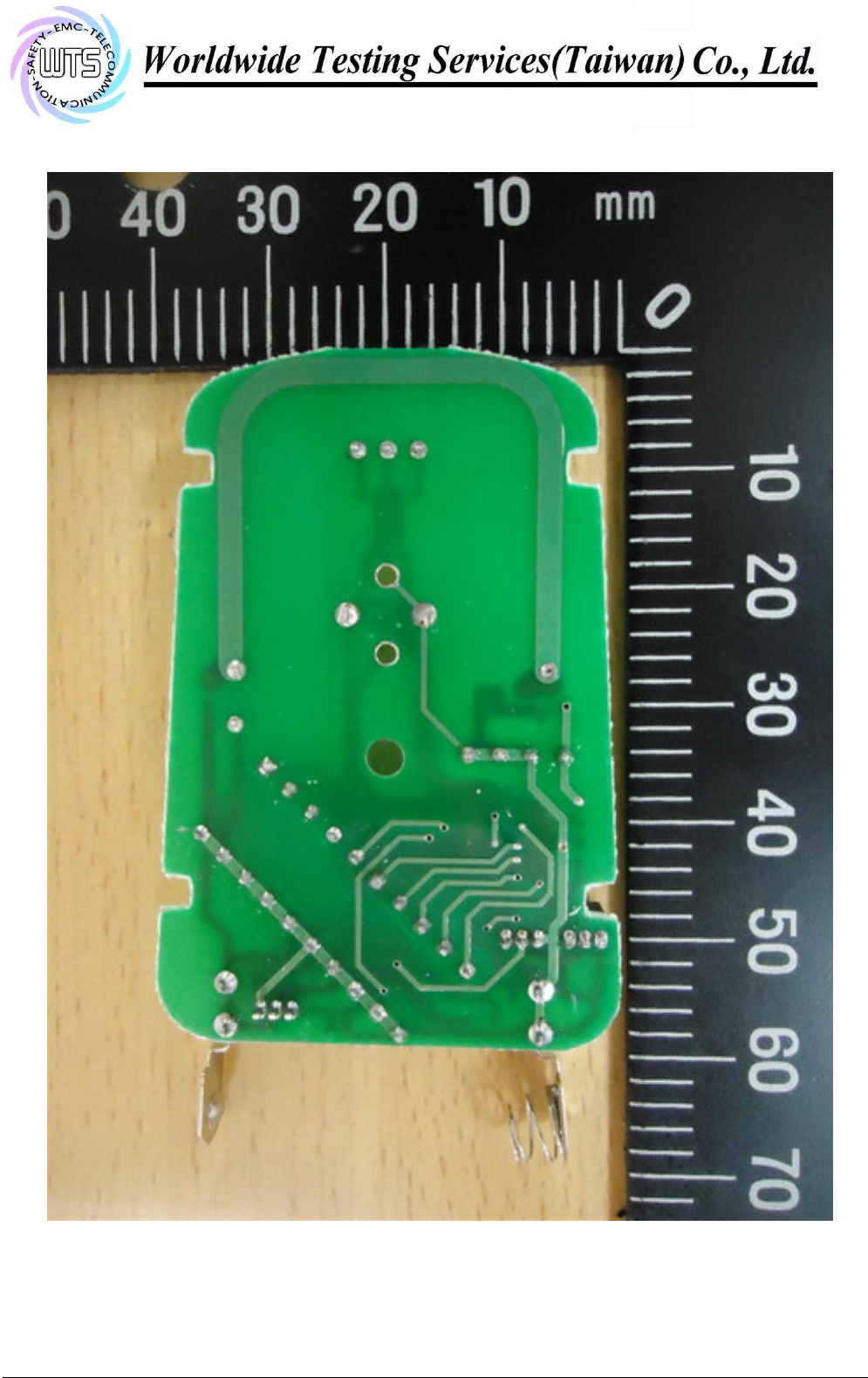
Explanation: This PCB antenna is integral antenna which passes antenna requirement.
The equipment meets the
requirements
yes
no

Registration number: W6M21409-14450-C-1
FCC ID: SU7300MCD21V2-CG
Worldwide Testing Services(Taiwan) Co., Ltd Page 18 of 19
3.8 Duty Cycle
The correction factor, based on the channel dwell time in a 100ms period, may be mathematically
applied to a measurement made with an average detector, to further reduce the measured value.
Average Reading = Peak Reading (dBuV/m) + Duty Cycle Correction
Duty Cycle Correction = 20 log (Cycle)
In order to determine the Duty Cycle, the EUT is measured as:
Testing Mode T period
(ms) T on
(ms) Duty Cycle Duty Cycle Correction
20*log(Duty Cycle)
Transmitting Mode 100 20.04008 0.200400802 -13.96
Explanation: See attached diagrams in appendix.
Test equipment used: ETSTW-RE 055, ETSTW-RE 004
Registration number: W6M21409-14450-C-1
FCC ID: SU7300MCD21V2-CG
Worldwide Testing Services(Taiwan) Co., Ltd Page 19 of 19
3.9 Conducted Measurement at (AC) Power Line
For an intentional radiator which is designed to be connected to the public utility (AC) power line, the
radio frequency voltage that is conducted back onto the AC line on any frequency or frequencies within
the band 150 kHz to 30 MHz shall not exceed the limits in the table bellows with this provision shall be
based on the measurement of the radio frequency voltage between each power line and ground at the
power terminals.
This measurement was transact first with instrumentation using an average and peak detector and a 10
kHz bandwidth. If the peak detector achieves a calculated level, the measurement is repeated by an
instrumentation using a quasi-peak detector.
Level
Frequency
quasi-peak (dBµV/m) average (dBµV/m)
-- kHz -- --
Note
1. The formula of measured value as: Test Result = Reading + Correction Factor
2. The Correction Factor = Cable Loss + LISN Insertion Loss + Pulse Limit Loss
3. Detector function in the form : PK = Peak, QP = Quasi Peak, AV = Average
4. All not in the table noted test results are more than 20 dB below the relevant limits.
5. Measurement uncertainty = ±1.41 dB; Reported uncertainties represent expanded uncertainties
expressed at approximately the 95% confidence level using a coverage factor of k = 2.
6. This test is not required because the EUT is battery-used.
Limits:
Frequency of Emission (MHz) Conducted Limit (dBuV)
Quasi Peak Average
0.15-0.5 66 to 56 56 to 46
0.5-5 56 46
5-30 60 50
Test equipment used: ETSTW-CE 001, ETSTW-CE 003, ETSTW-CE 016, ETSTW-RE 045

Registration number: W6M21409-14450-C-1
FCC ID: SU7300MCD21V2-CG
Worldwide Testing Services(Taiwan) Co., Ltd Appendix Page 1 of 20
Appendix
A Measurement diagrams
1. Active Time
2 . Output Power
3. Spurious Emissions radiated
4. Bandwidth
5. Duty Cycle
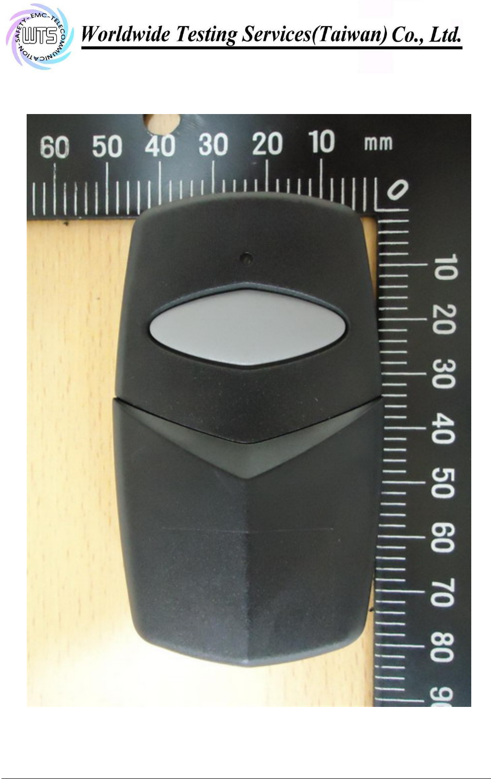
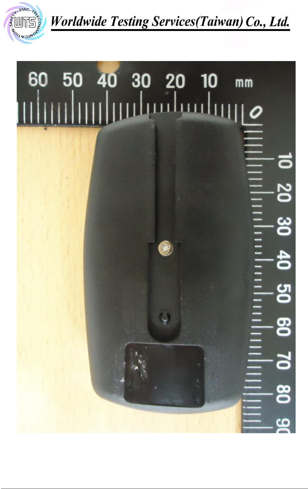
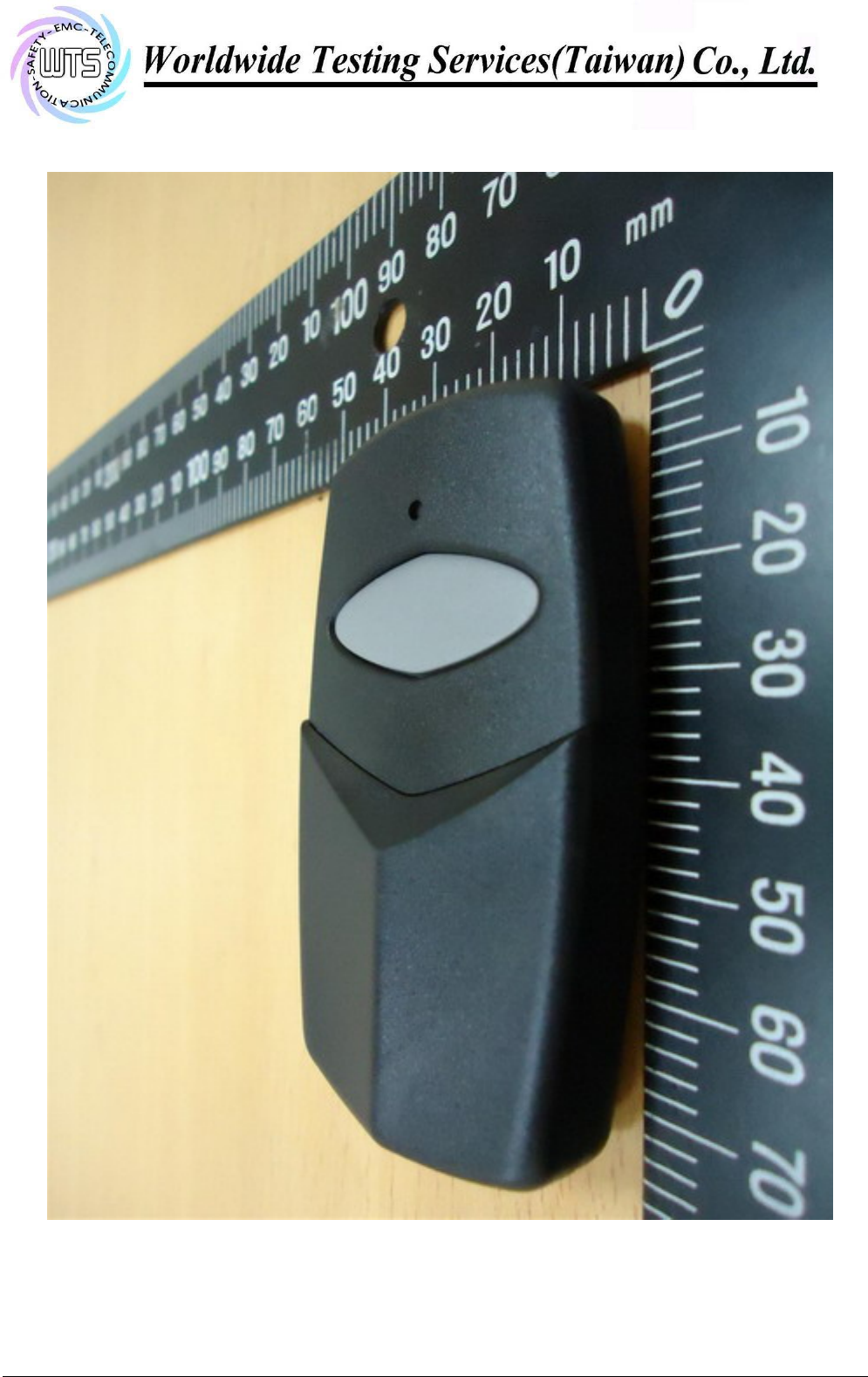
B Photos
1. External Photos
2. Internal Photos
3. Set Up Photos
Registration number: W6M21409-14450-C-1
FCC ID: SU7300MCD21V2-CG
Worldwide Testing Services(Taiwan) Co., Ltd Appendix Page 2 of 20
Active Time
Registration number: W6M21409-14450-C-1
FCC ID: SU7300MCD21V2-CG
Note:
Up Line: Peak Limit Line, Down Line: Ave Limit Line
1. The attached measurement plots are preliminarily pre-scanned with peak detector for determining the final
checking frequencies and are for reference only.
2. The some frequencies may exceed the limit line without the specified detectors, but that cannot present the
results are failed to the specification of test standard.
3. For corrected test results are listed in the relevant table of Field Strength test data of this test report.
Worldwide Testing Services(Taiwan) Co., Ltd Appendix Page 3 of 20
Output Power
Antenna Polarization H
Antenna Polarization V
Registration number: W6M21409-14450-C-1
FCC ID: SU7300MCD21V2-CG
Note:
Up Line: Peak Limit Line, Down Line: Ave Limit Line
1. The attached measurement plots are preliminarily pre-scanned with peak detector for determining the final
checking frequencies and are for reference only.
2. The some frequencies may exceed the limit line without the specified detectors, but that cannot present the
results are failed to the specification of test standard.
3. For corrected test results are listed in the relevant table of radiated test data of this test report.
Worldwide Testing Services(Taiwan) Co., Ltd Appendix Page 4 of 20
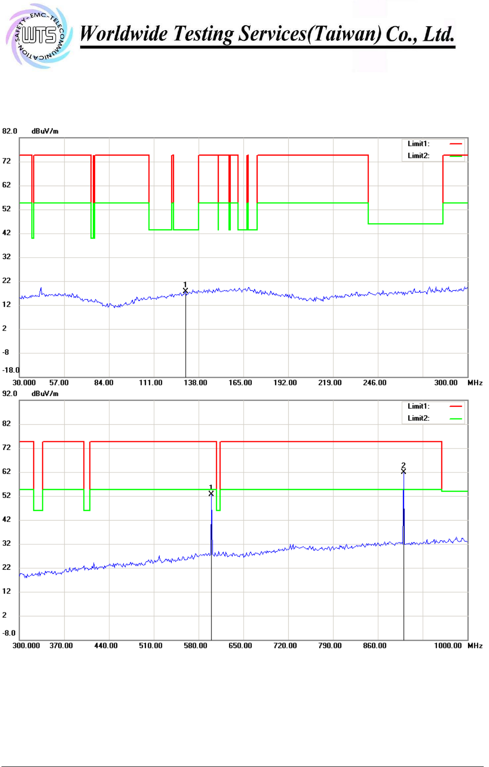
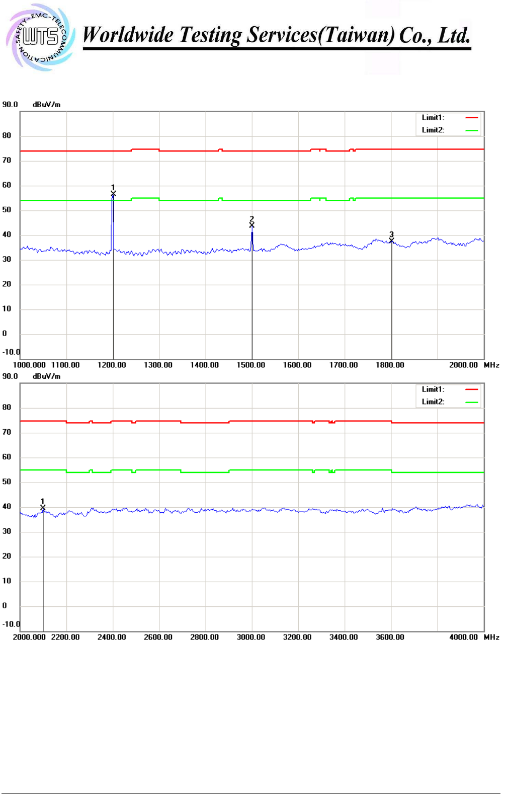
Spurious Emissions radiated
Antenna Polarization H
Registration number: W6M21409-14450-C-1
FCC ID: SU7300MCD21V2-CG
Note:
Up Line: Peak Limit Line, Down Line: Ave Limit Line
1. The attached measurement plots are preliminarily pre-scanned with peak detector for determining the final
checking frequencies and are for reference only.
2. The some frequencies may exceed the limit line without the specified detectors, but that cannot present the
results are failed to the specification of test standard.
3. For corrected test results are listed in the relevant table of radiated test data of this test report.
Worldwide Testing Services(Taiwan) Co., Ltd Appendix Page 5 of 20
Registration number: W6M21409-14450-C-1
FCC ID: SU7300MCD21V2-CG
Note:
Up Line: Peak Limit Line, Down Line: Ave Limit Line
1. The attached measurement plots are preliminarily pre-scanned with peak detector for determining the final
checking frequencies and are for reference only.
2. The some frequencies may exceed the limit line without the specified detectors, but that cannot present the
results are failed to the specification of test standard.
3. For corrected test results are listed in the relevant table of radiated test data of this test report.
Worldwide Testing Services(Taiwan) Co., Ltd Appendix Page 6 of 20
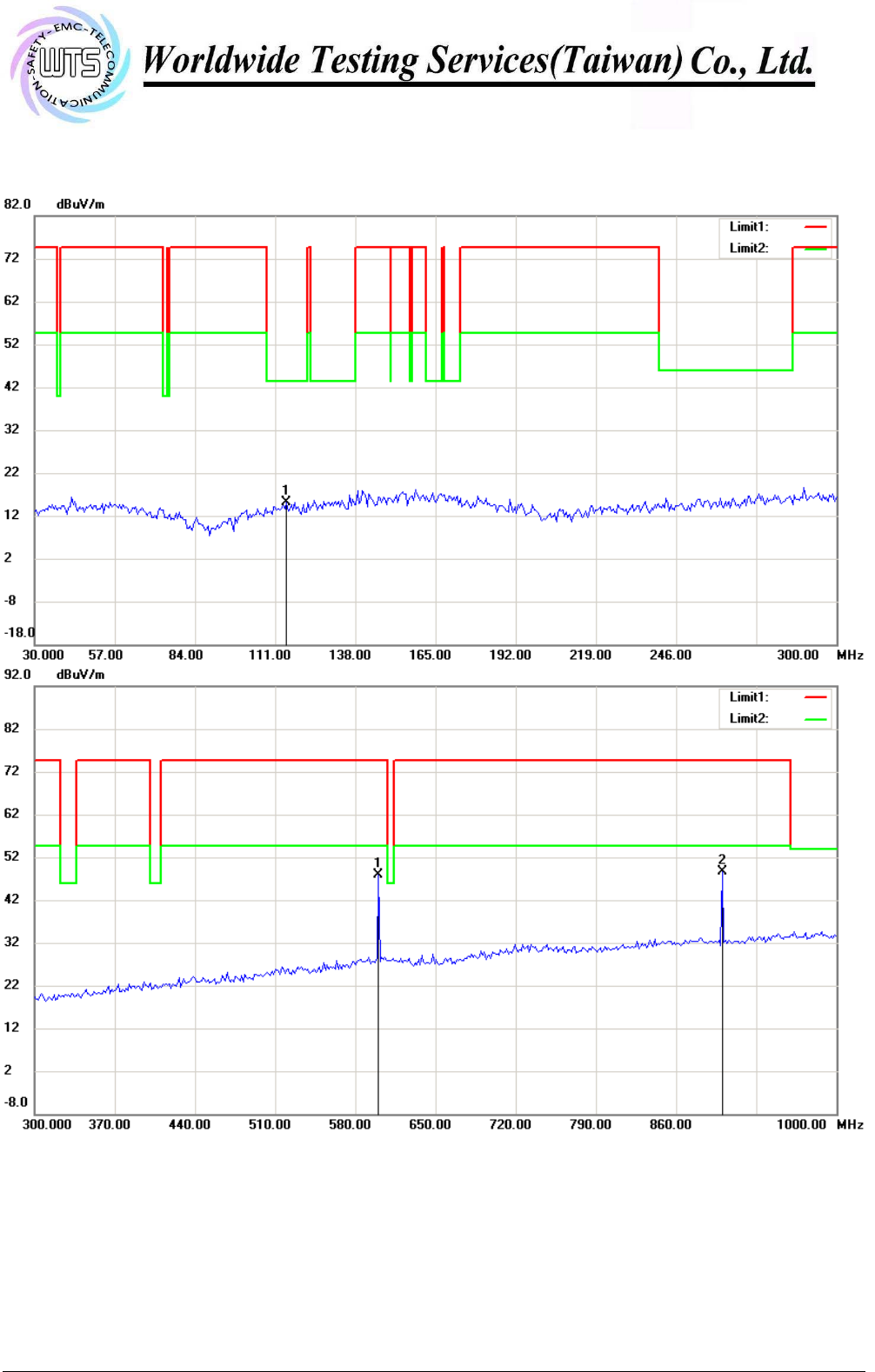
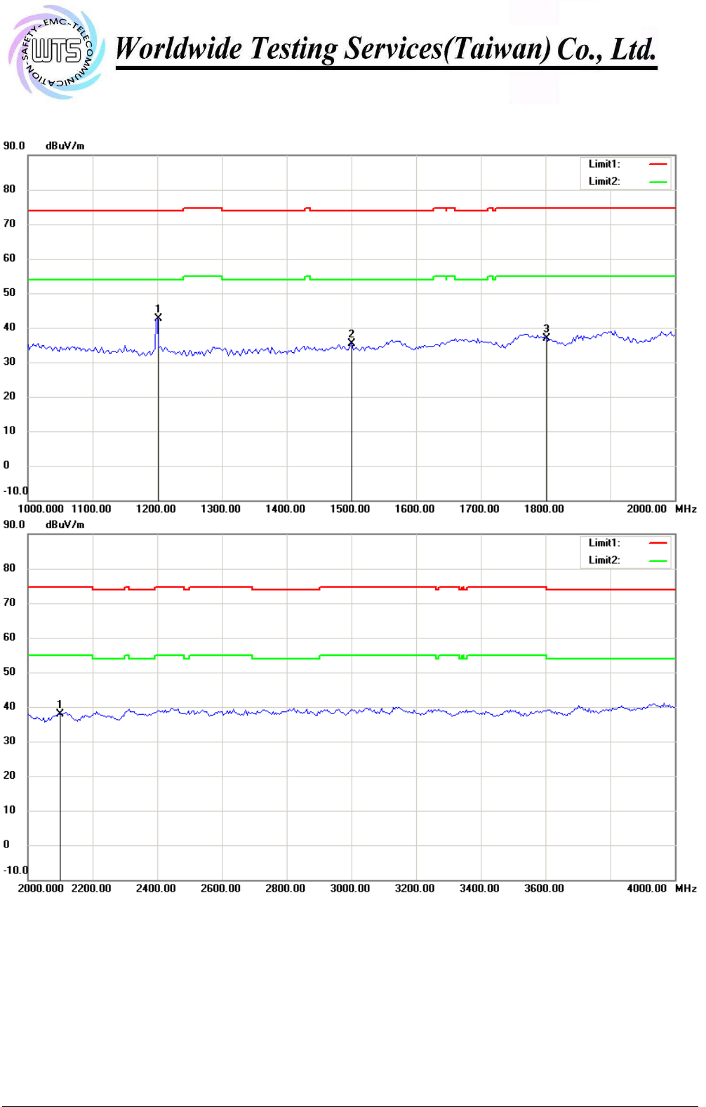
Antenna Polarization V
Registration number: W6M21409-14450-C-1
FCC ID: SU7300MCD21V2-CG
Note:
Up Line: Peak Limit Line, Down Line: Ave Limit Line
1. The attached measurement plots are preliminarily pre-scanned with peak detector for determining the final
checking frequencies and are for reference only.
2. The some frequencies may exceed the limit line without the specified detectors, but that cannot present the
results are failed to the specification of test standard.
3. For corrected test results are listed in the relevant table of radiated test data of this test report.
Worldwide Testing Services(Taiwan) Co., Ltd Appendix Page 7 of 20
Registration number: W6M21409-14450-C-1
FCC ID: SU7300MCD21V2-CG
Worldwide Testing Services(Taiwan) Co., Ltd Appendix Page 8 of 20
Bandwidth
Duty Cycle
Registration number: W6M21409-14450-C-1
FCC ID: SU7300MCD21V2-CG
Worldwide Testing Services(Taiwan) Co., Ltd Appendix Page 9 of 20
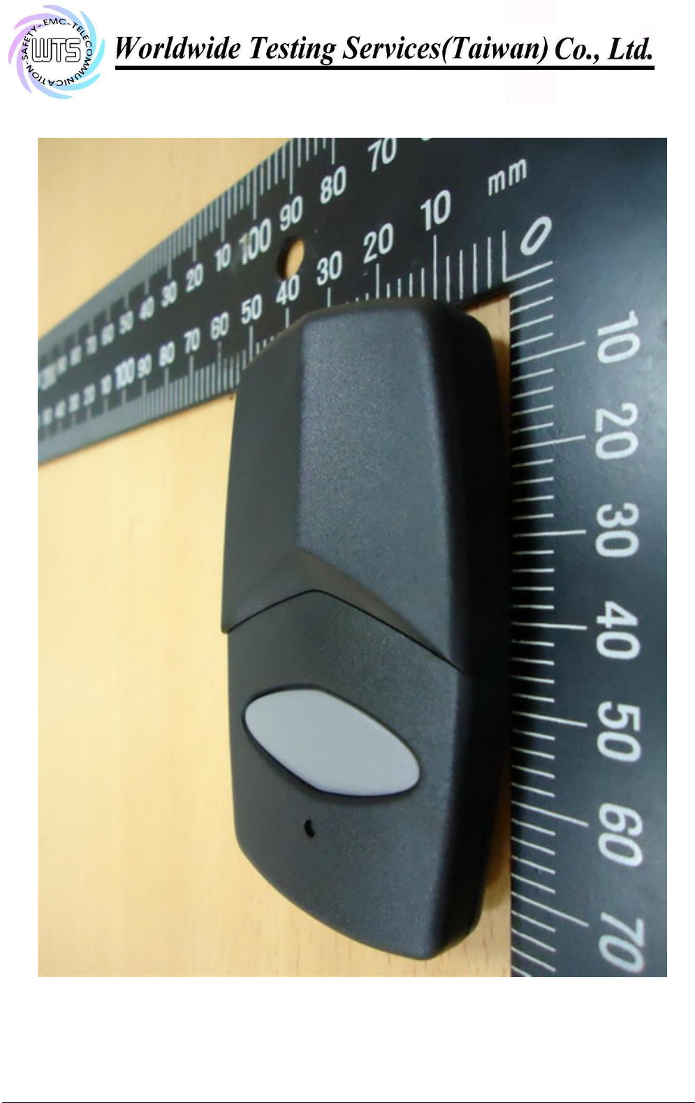
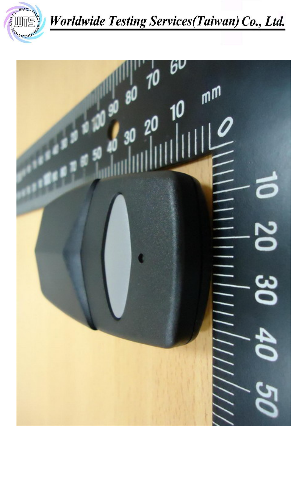
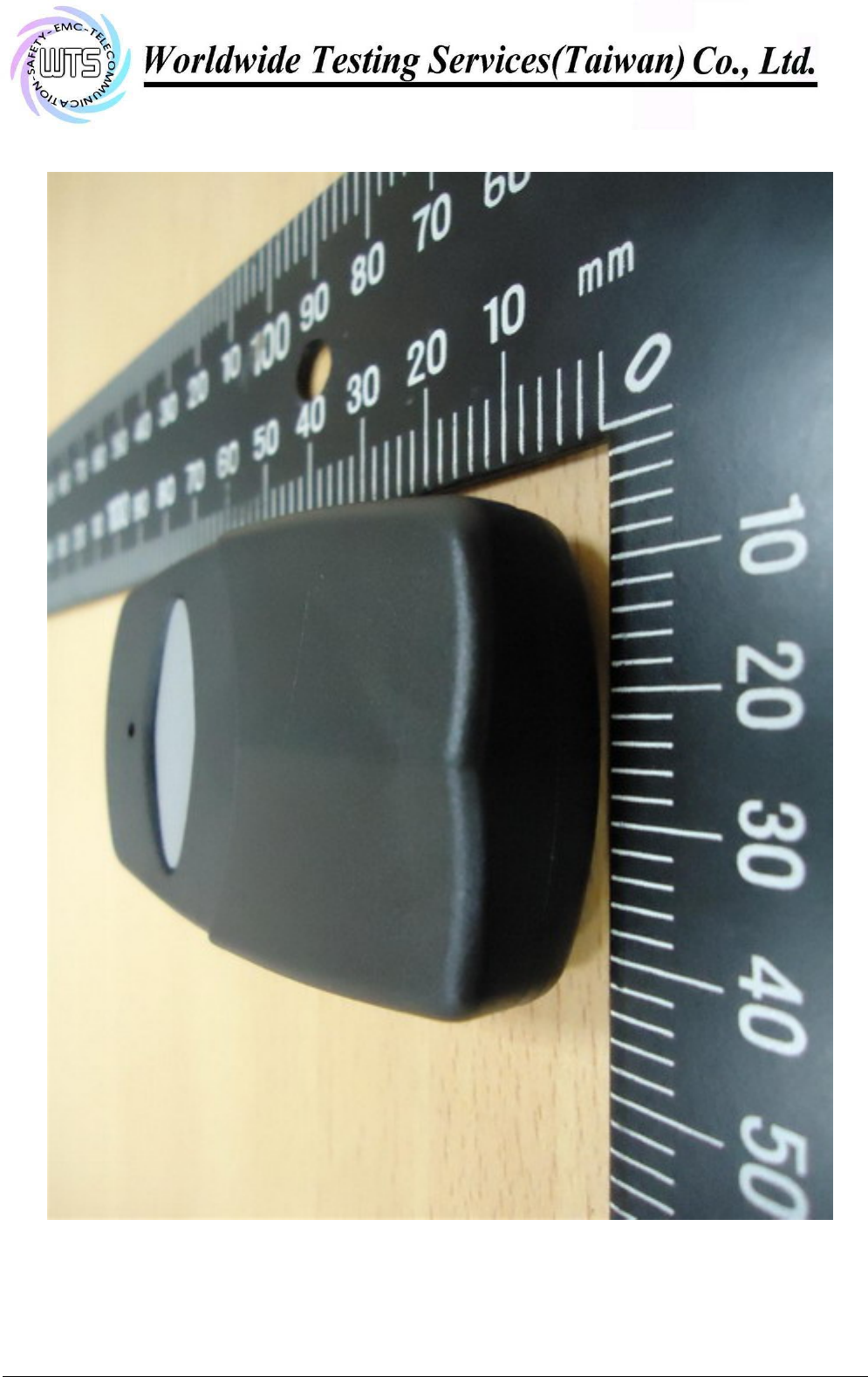
External Photos
Registration number: W6M21409-14450-C-1
FCC ID: SU7300MCD21V2-CG
Worldwide Testing Services(Taiwan) Co., Ltd Appendix Page 10 of 20
Registration number: W6M21409-14450-C-1
FCC ID: SU7300MCD21V2-CG
Worldwide Testing Services(Taiwan) Co., Ltd Appendix Page 11 of 20
Registration number: W6M21409-14450-C-1
FCC ID: SU7300MCD21V2-CG
Worldwide Testing Services(Taiwan) Co., Ltd Appendix Page 12 of 20
Registration number: W6M21409-14450-C-1
FCC ID: SU7300MCD21V2-CG
Worldwide Testing Services(Taiwan) Co., Ltd Appendix Page 13 of 20
Registration number: W6M21409-14450-C-1
FCC ID: SU7300MCD21V2-CG
Worldwide Testing Services(Taiwan) Co., Ltd Appendix Page 14 of 20
Registration number: W6M21409-14450-C-1
FCC ID: SU7300MCD21V2-CG
Worldwide Testing Services(Taiwan) Co., Ltd Appendix Page 15 of 20
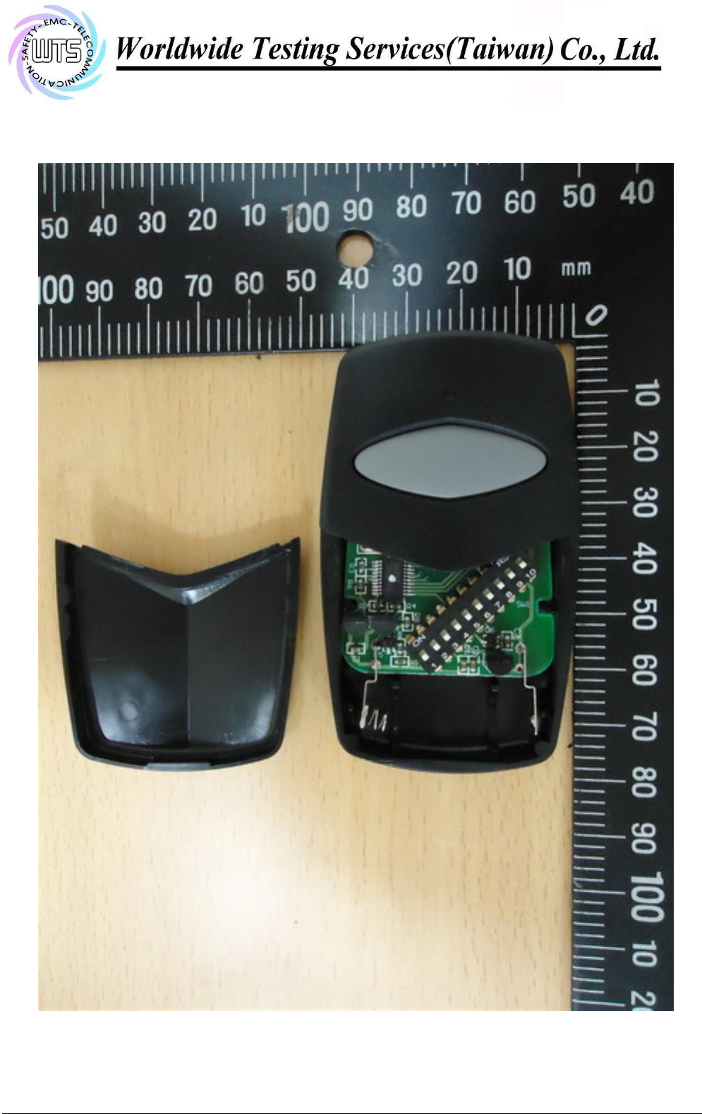
Internal Photos
Registration number: W6M21409-14450-C-1
FCC ID: SU7300MCD21V2-CG
Worldwide Testing Services(Taiwan) Co., Ltd Appendix Page 16 of 20
Registration number: W6M21409-14450-C-1
FCC ID: SU7300MCD21V2-CG
Worldwide Testing Services(Taiwan) Co., Ltd Appendix Page 17 of 20
Registration number: W6M21409-14450-C-1
FCC ID: SU7300MCD21V2-CG
Worldwide Testing Services(Taiwan) Co., Ltd Appendix Page 18 of 20
Registration number: W6M21409-14450-C-1
FCC ID: SU7300MCD21V2-CG
Worldwide Testing Services(Taiwan) Co., Ltd Appendix Page 19 of 20
Registration number: W6M21409-14450-C-1
FCC ID: SU7300MCD21V2-CG
Worldwide Testing Services(Taiwan) Co., Ltd Appendix Page 20 of 20
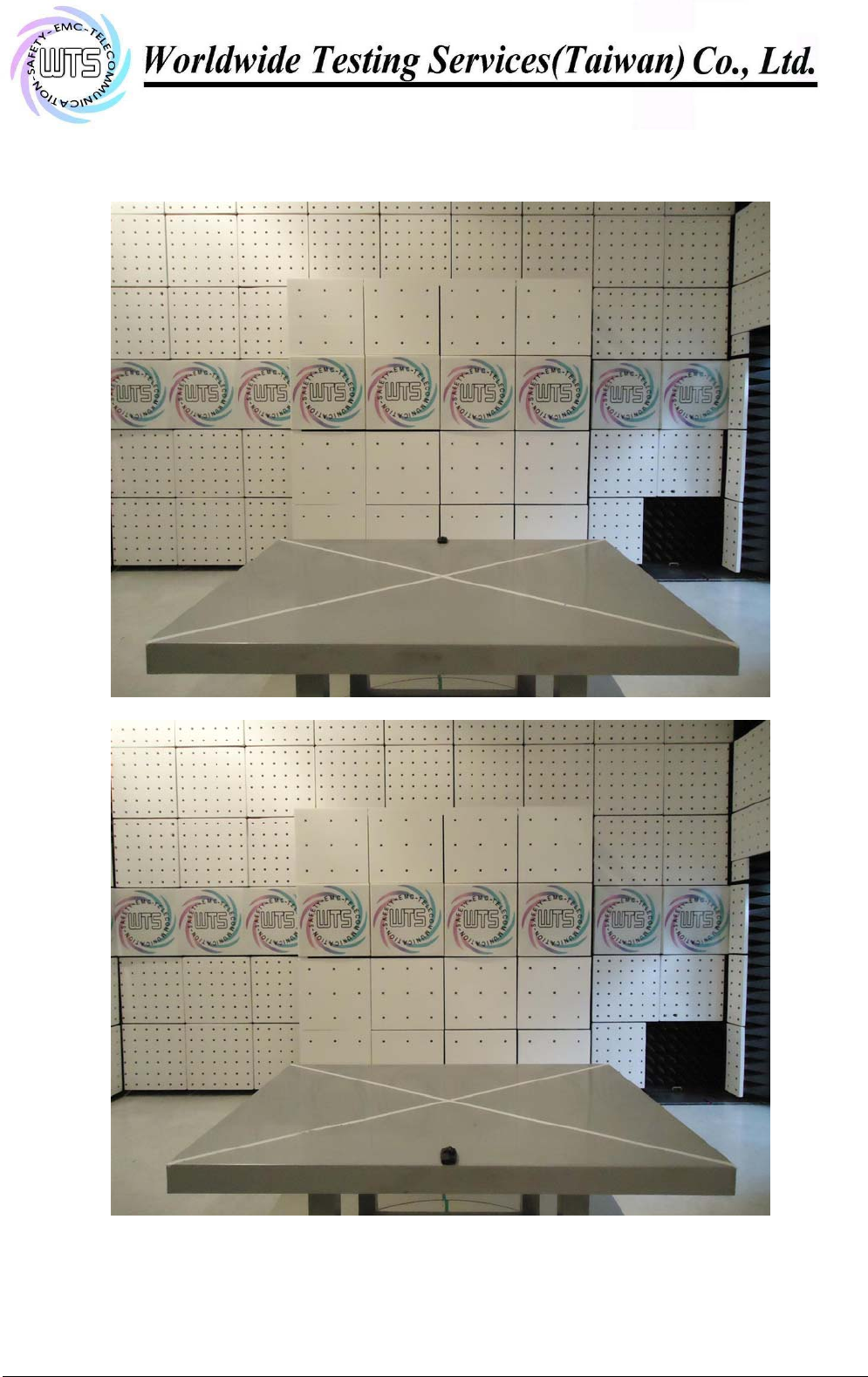
Set Up Photos of Radiated emission