Controlled Entry Distributors 418ELPW1K Model 418ELPW1K User Manual Exhibit 8
Controlled Entry Distributors, Inc. Model 418ELPW1K Exhibit 8
Exhibit 8
ELPRO INNOTEK S.p.A.
TCF-107
MONARCH ONE BUTTON - Type:
418ELPW1K
Annex 8 : User manual
CONTENTS
1A - General information
1B - Technical specifications
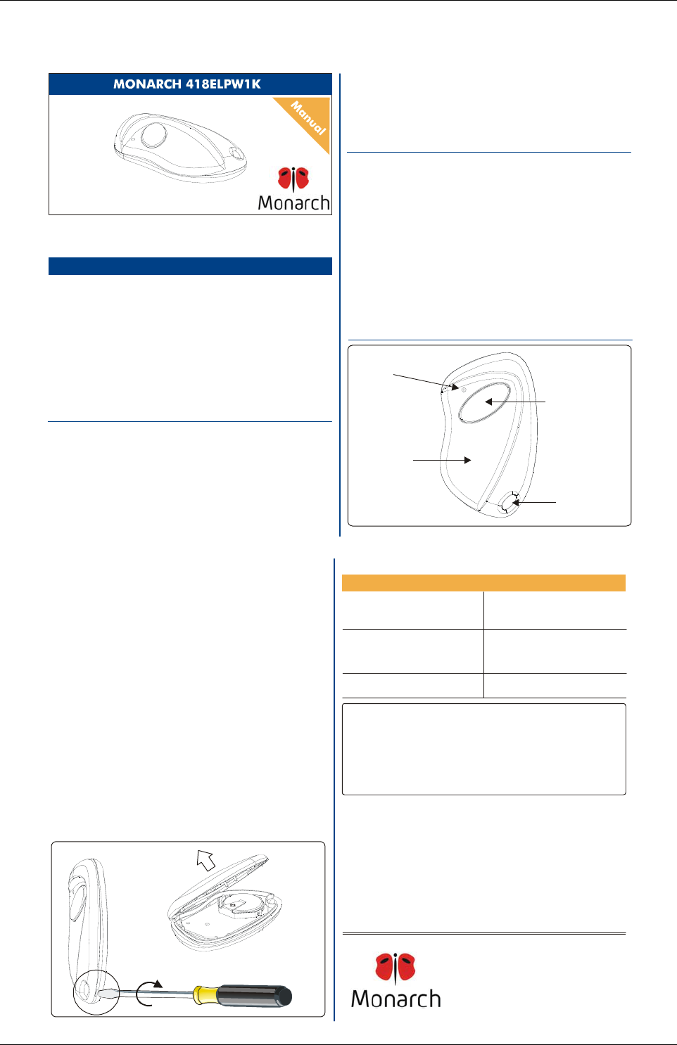
1C - Main components
1 - TRANSMITTER OVERVIEW
2 - NUMBERING
3 - PROGRAMMING
4 - OPERATION
5 - BATTERY ACCESS
1B - Technical specifications
Operating frequency 418 MHz
Number of keys: 1
Battery life: 18 24 months
Battery : 2 x 3V lithium batteries CR2016
÷
Number combinations : 65,536
Protocol : Elite compatible
Different Facilities codes 256
Operating temperature: -20°F÷+131°F (-20°C÷+55°C)
Overall dimensions: 2.4”x1.4”x0.51” (61x36x13 mm)
Weight: 0.49 oz. (14 gr.)
1C - Main components
Red
LED
Key
holder
ring
Green
push-button
6 - TROUBLESHOOTING
Dark grey
case
Fig. 2
1A - General information
The Transmitter Solutions - Monarch 418ELPW1K transmitter is a key
chain style mini transmitter operating at 418 MHz. It has been designed
for use with programmable telephone entry, security, and access control
systems operating with a 418 MHz frequency receiver. The code sent by
the transmitter includes a 16 bit security code which allows up to
65,536 code combinations and 8 bits of facility code which allows up to
256 facility codes .
The Transmitter Solutions - 418R receiver which operates with this
transmitter has a Wiegand 26 bit output and can operate any type of
access control system equipped with the same protocol. The CR 2016
lithium batteries of the transmitter have a shelf life of about 6 months.
Part 15 of FCC Regulations and The product fully complies with the
European Directives 99/5/CE, 89/336/CEE, 73/23/CEE.
Transmitter
Solutions
Thank you for choosing a Transmitter Solutions product .
Please read this manual carefully before using the product.
Made in Italy. Copyright
© 2006 by Transmitter Solutions
2 - NUMBERING 6 - TROUBLESHOOTING
PROBLEM SOLUTION
The operating range is reduced
Check to verify the
transmitter is programmed
into your system
Replace the transmitter
batteries
IS-TM141CCUK Rev. 1 del 19.05.2006
To access the battery open the case with a screwdriver acting on the slot between
the cover and the bottom and remove the bottom, as shown in fig. 3a and 3b.
Slide out the old batteries and replace them with the new ones ]
respecting the polarity, with the positive (+) side upward.
[CR2016
NOTE: Please dispose of the batteries properly according to local laws and
regulations.
Test proper battery installation by verifying that the red LED illuminates when
the button is pushed.
5 - BATTERY ACCESS
3 - PROGRAMMING
Each transmitter is manufactured and sold with a different factory-set serial
number .
The transmitter must be programmed into your system memory.
Your own installer or reseller will provide you the necessary instructions for your
system.
Replace the transmitter
batteries
The warranty period of 418 transmitters is 24 months,
beginning from the manufacturing date of the transmitter. During this period, if the
product does operate correctly, due to a defective component, the product will be
repaired or replaced at the sole discretion of .
The warranty does not extend to the transmitter case which can be damaged by
conditions outside the control of or to battery life.
Transmitter Solutions
Tra nsm itt er Solution s
Tra nsm itt er Solution s
WARRANTY
Transmitter Solutions - Type : 418ELPW1K
FCC ID : SU7418ELPW1K
This device complies with FCC Rules
Operation is subject to the following two conditions:
(1) This device may not cause harmful interference, and
(2) this device must accept interference received, including
interference that may cause undesired operation.
Part. 15 of the
Notice
Any changes or modification to equipment not expressly
approved by could void the manufacturer’s warranty.
Transmitter Solutions
Transmitter Solutions
The system does not receiver the
transmitter signal.
The transmitter LED is ON
The system does not receiver the
transmitter signal.
The transmitter LED will not light
4 - OPERATION
A - Firmly depress the button until the small red LED illuminates.
B - After the LED has illuminated, release the button.
If the device you are attempting to activate does not respond, repeat steps A and B
or consult section 6 ( Troubleshooting ) of this manual.
Fig. 3a
Fig. 3b
TRANSMITTER SOLUTIONS
2505 Chandler Avenue, Suite, 1
Las Vegas, NV 89120 -
(866) 975-0101 - (866) 975-0404 Fax
sales@transmittersolutions.com
Annex 8 = User manual Pag 1 of 1