Controlled Entry Distributors RCOO900P Remote Controller User Manual
Controlled Entry Distributors, Inc. Remote Controller Users Manual
Users Manual
iGAZE® REP KIT
BI-DIRECTIONAL
COMMUNICATION
Movable Device
TCOO900
Fixed Device
RCOO900P
INSTRUCTION MANUAL
v.05.24.18
Transceiver System for 10kΩ, or 8.2kΩ
Resistive Safety Edges
Pulsed output
2
TRANSCEIVER SYSTEM FOR SAFETY EDGES
TECHNICAL SPECIFICATIONS
QUICK START GUIDE
BELOW IS THE MOST COMMON INSTALLATION
Movable device name TCOO900
Fixed device name RCOO900P
Frequency 902-928 Mhz
Range of the system in free space 20 m / 60 feet
TCOO900 power supply 2 x 1.5V batteries (AA)
RCOO900P power supply 12/24 Vac-dc
Battery duration 2 years (normal functioning mode).
5 years (Low power mode).
Minimum battery level (TCOO900) 1.9V
Compatible safety edges (TCOO900) Resistive (8.2 kΩ / 10kΩ)
Number of outputs (RCOO900P) 2
Maximum number of Transmitters for each
RCOO900P
8 for each device.
Maximum number of safety edges for each output 8 for each relay.
Power draw on RCOO900P (24Vdc) 15mA (3-wire or 4-wire pulsed)
50mA (2-wire pulsed)
Resistive Safety Edge (max value) 5kOhm < R < 20KOhm (safety edge OK)
R<5KOhm (safety edge in short circuit)
R>20KOhm (OPEN safety edge)
Frequency for alternate current (RCOO900P) 50-60Hz
Operating Temperature -10°C to +55°C / 14°F to 131°F
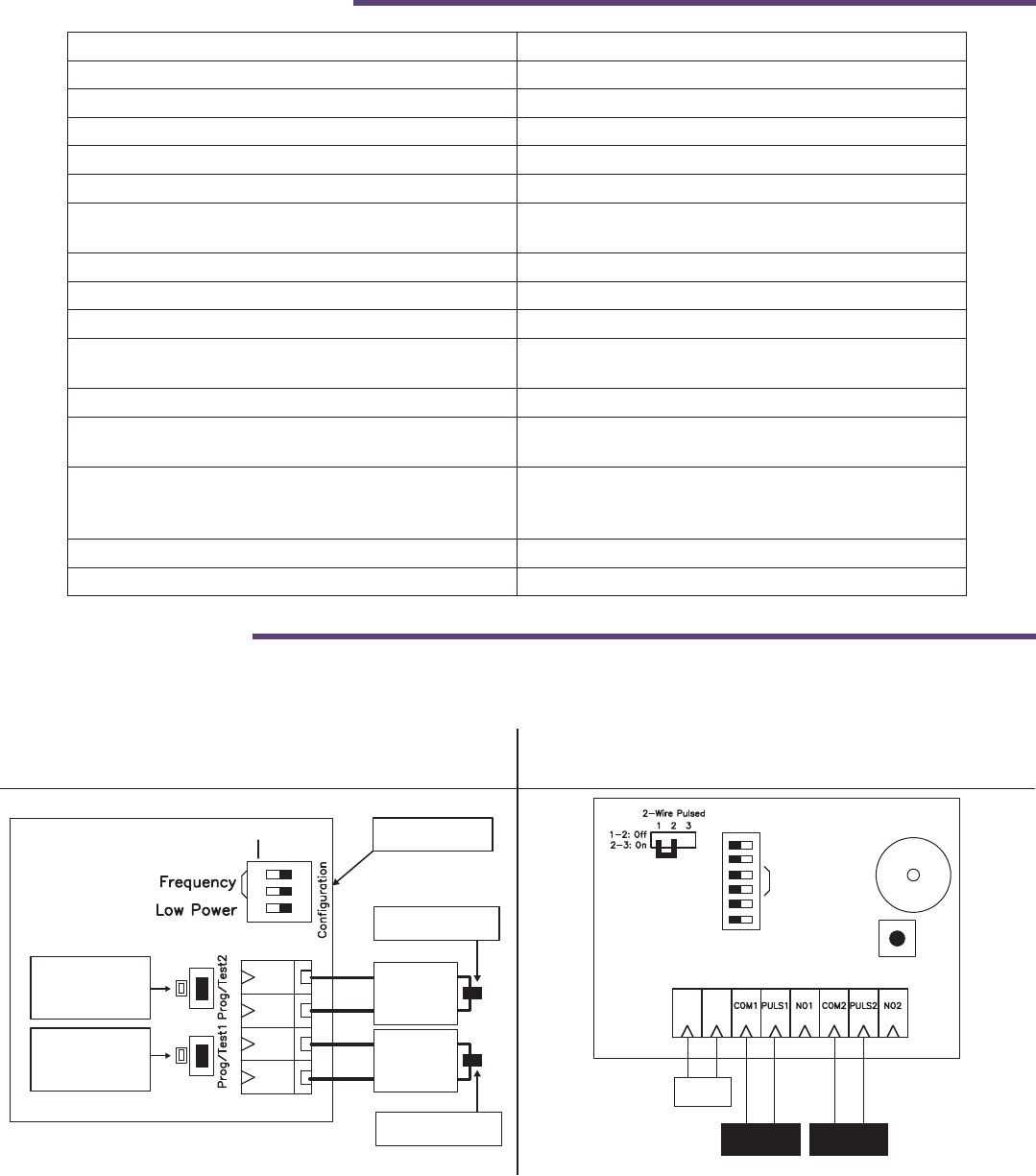
TCOO900 - Both safety edges are 8.2kΩ or
10kΩ resistive.
RCOO900P - Pulsed 2 Frequency on both
channels
12 3 OFF
ON
Resistive
edge 2
Resistive
edge 1
Resistive edge 2
8.2kΩ / 10kΩ (N.C.)
Dip switch
Led and
programming /
test key 2
Led and
programming /
test key 1
Resistive edge 1
8.2kΩ / 10kΩ (N.C.)
Safety2
Safety1
DIP
12/24
Vac/Vdc
+-
operator 1
pulsed input
operator 2
pulsed input
2Freq/3Freq
Buzzer OFF
Frequency
Out1 - 10k
Out2 - 10k
OFF ON
Programming/
Reset key
Buzzer
RCO900P
3
STEP 2
STEP 1
DESCRIPTION
CONFIGURATION AND ELECTRICAL CONNECTIONS
The iGAZE® REP transceiver system is intended as a safety device for automated gates and rolling doors. The system is
comprised of 1 fixed device (RC00900P) with 2 pulsed outputs, which is connected to the operator, and up to 8 movable
devices (TC00900) for each relay. The system TCOO900 will accept only resistive safety edge 10kΩ or 8.2kΩ. The
transmission signal is bi-directional and utilizes the frequencies 902-928MHz. Maximum range between the movable and
fixed devices is 60 feet.
TCOO900 is suitable for outdoor use. RCOO900P is suitable for indoor use only (“indoor” means inside the
operator box). The installation of the system must be carried out by a qualified installer.
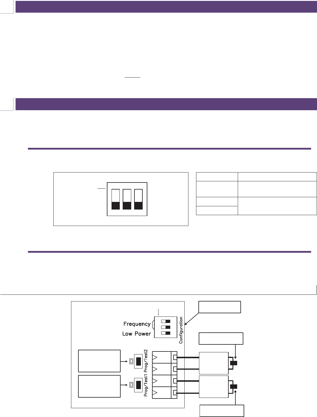
CONNECT THE SAFETY EDGE TO THE SAFETY EDGE MOVABLE DEVICE (TCOO900)
DIP SWITCHES CONFIGURATION OF TCOO900
EXAMPLE 1 - Both safety edges are 8.2kΩ or 10kΩ resistive
12 3 OFF
ON
Resistive
edge 2
Resistive
edge 1
Resistive edge 2
8.2kΩ / 10kΩ (N.C.)
Dip switch
Led and
programming /
test key 2
Led and
programming /
test key 1
Resistive edge 1
8.2kΩ / 10kΩ (N.C.)
Safety2
Safety1
DIP
123
TCOO900
DIP
ON
OFF
(All switches in example above are set to OFF)
A
B
N°DIP Function
1Low Power (see section E on
page 9)
2Frequency channel selection
(see page 4)
3
ATTENTION! If external operators or devices are installed, wiring type CL2, CL2P, CL2R or CL2X complying with UL 13 or
other cable with equivalent or better electrical, mechanical, and flammability ratings shall be used.
4
STEP 3
STEP 4
It is possible to associate a maximum of 8 TCOO900
to each RCOO900P.
WARNING: for a correct functioning of the system,
every TCOO900 must have the frequency dip
switch set the same way as the corresponding
RCOO900P.
On a safety system with more than one Receiver, to avoid interference, we recommend the use of dierent frequency
settings on each set of a RCOO900P and the associated TCOO900.
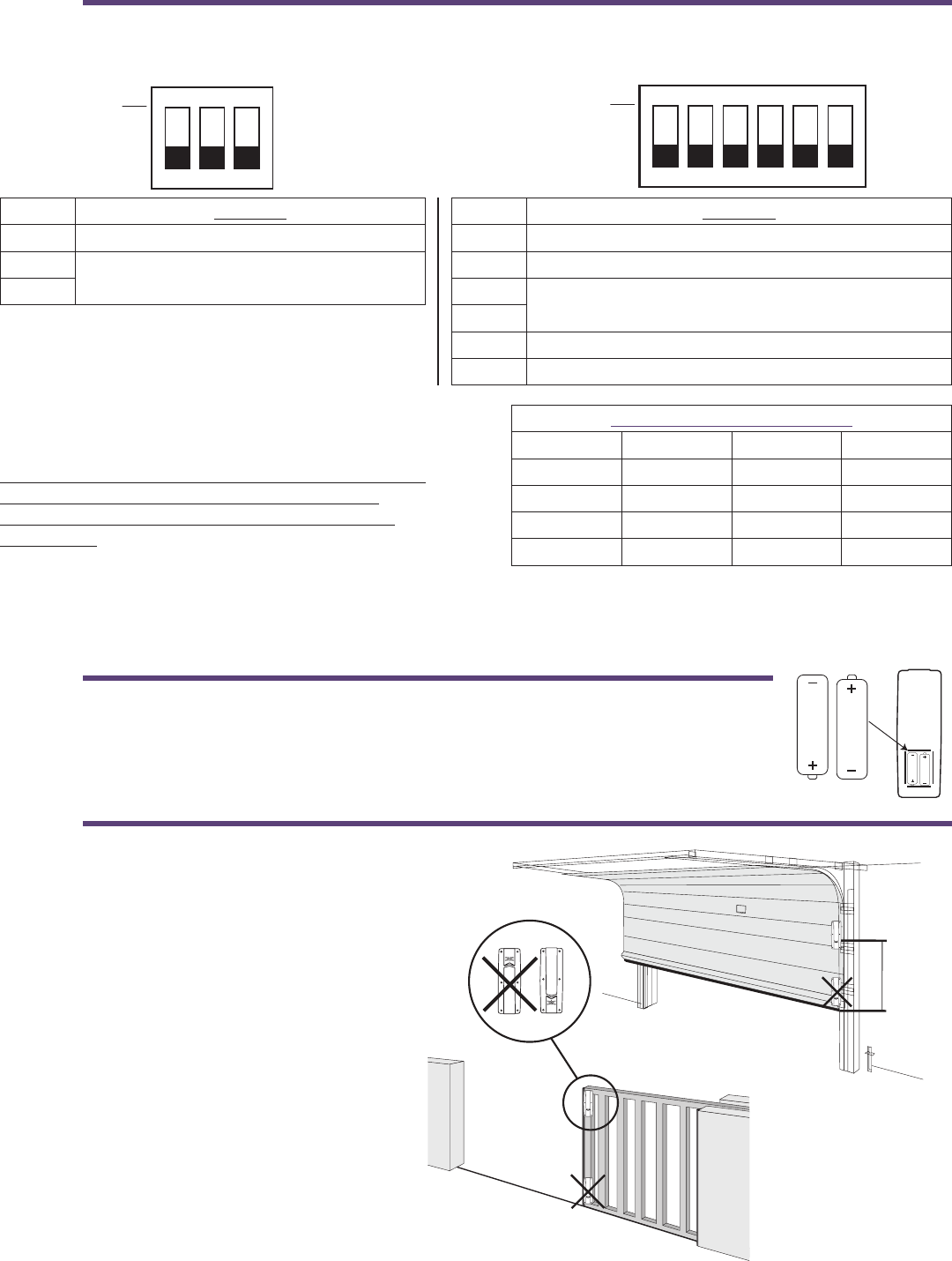
POWER THE TCOO900 BY INSTALLING THE TWO AA BATTERIES (1.5V) INTO THE
BATTERY HOLDER. PLEASE NOTE THE CORRECT POLARITY.
1.5V
1.5V
N° DIP Function
1 Low power. (see Section E on page 9)
2Frequency channel selection
3
N° DIP Function
1 2 Freq / 3 Freq
2 Buzzer ON / OFF
3Frequency channel selection
4
5 Out1 type: N.O. contact (OFF) or 10k signal (ON) 1
6 Out2 type: N.O. contact (OFF) or 10k signal (ON) 2
Frequency channel selection
Channel Dip 3 (2) Dip 4 (3) Frequency
1 OFF OFF 912.900
2 OFF ON 914.900
3 ON OFF 916.900
4 ON ON 918.900
SET DIP SWITCHES 2 AND 3 ON THE TCOO900 AND 3 AND 4 ON THE RCOO900P TO THE SAME SETTINGS.
123
TCOO900
DIP
ON
OFF
123
RCOO900P
DIP
ON
OFF
4 5 6
STEP 5
Height min: 8”
Height
min: 8”
MOUNT THE TCOO900 AS HIGH AS POSSIBLE
AND IN SUCH A WAY AS THERE ARE NO
OBSTACLES IN THE DIRECTION OF THE
RCOO900P AND IN SUCH A WAY AS THE
MAXIMUM DISTANCE BETWEEN THE TWO
DEVICES IS LESS THAN 60 FEET (MAX 20
METERS / 60 FEET).
WARNING: install the TCOO900 at a minimum
height of 8” from the ground.
Keep the installation area clean of debris which
can eect the normal operation of the system.
NOTE: Transmitter Solutions is not responsible for
any damage caused by an improper, incorrect, or
unintended use of the product.
5
STEP 6
STEP 7
MOUNT THE RCOO900P AS CLOSE AS POSSIBLE TO THE TCOO900. IF MOUNTED TO A WALL, USE SUITABLE
SCREWS AND ANCHORS TO SECURE THE RCOO900P.
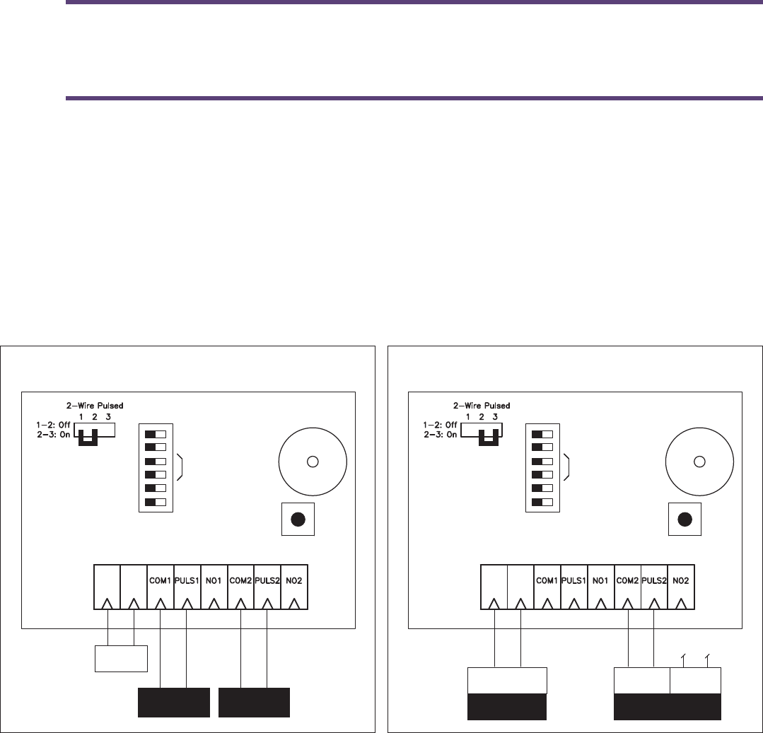
DEPENDING ON THE TYPE OF SIGNAL REQUIRED, CONNECT THE OUTPUTS AS EXPLAINED IN THE
FOLLOWING EXAMPLES.
NOTE: The signals given on the outputs 1 and 2 are a N.O. contact, resistive output (10kΩ) or pulsed output, depending on
the setting of dip switches 5 and 6, and the wiring connection.
NOTE: The level of acoustic noise generated by the device is less than 70 dBA.
EXAMPLE 1 - Pulsed 2 Frequency on both channels EXAMPLE 2 - Pulsed 2-wire on channel 1 and pulsed
4-wire on channel 2
12/24
Vac/Vdc
+-
operator 1
pulsed input
operator 2
pulsed input
2Freq/3Freq
Buzzer OFF
Frequency
Out1 - 10k
Out2 - 10k
OFF ON
Programming/
Reset key
Buzzer
RCO900P
12/24Vdc
Power / Signal
+-
Operator 1
2-wire pulsed
Signal
2Freq/3Freq
Buzzer OFF
Frequency
Out1 - 10k
Out2 - 10k
OFF ON
Programming/
Reset key
Buzzer
RCO900P
Power
Operator 2
4-wire pulsed
not connected
WARNING: The power supply for the receiver must be an insulated transformer to protect against short circuits
6
STEP 8 STEP 9
MOUNT THE IGAZE® REP RCOO900P POWER THE RCOO900P WITH 12-24 VAC/DC
INSULATED POWER SUPPLY (NOT INCLUDED WITH
THE IGAZE® REP KIT).
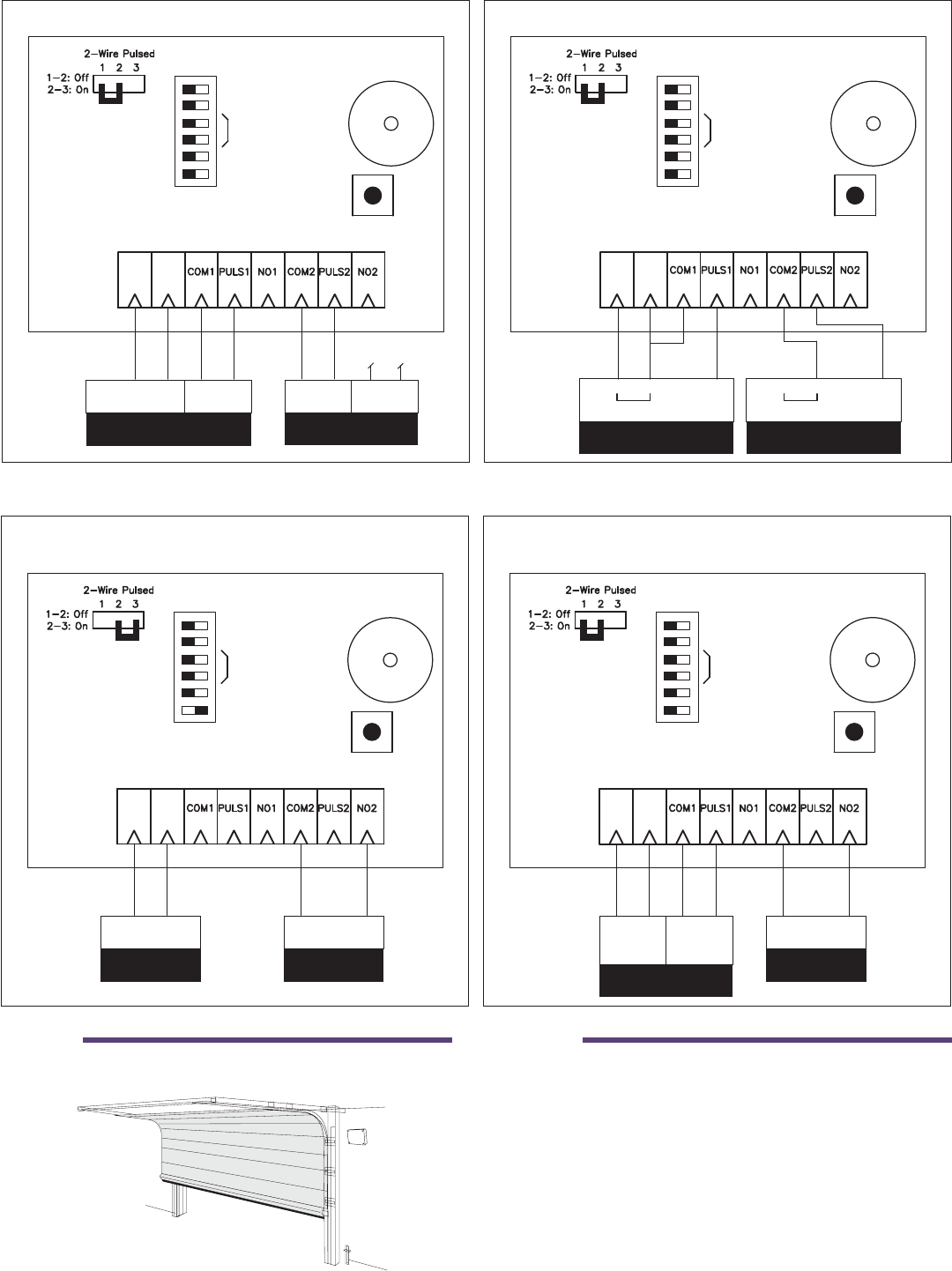
EXAMPLE 3 - Pulsed 4-wire on both channels EXAMPLE 4 - Pulsed 3-wire on both channels
12/24 Vac/Vdc
Power
+-
Operator 1
4-wire pulsed
Signal
2Freq/3Freq
Buzzer OFF
Frequency
Out1 - 10k
Out2 - 10k
OFF ON
Programming/
Reset key
Buzzer
RCO900P
Power
not connected
Signal
Operator 2
4-wire pulsed
+-
2Freq/3Freq
Buzzer OFF
Frequency
Out1 - 10k
Out2 - 10k
OFF ON
Programming/
Reset key
Buzzer
RCO900P
POWER
Operator 1
3-wire pulsed
12/24 Vac/Vdc
COM Signal POWER
Operator 2
3-wire pulsed
12/24 Vac/Vdc
COM Signal
EXAMPLE 5 - Pulsed 2-wire on channel 1 and 10k on
channel 2
EXAMPLE 6 - Pulsed 4-wire on channel 1 and N.O. on
channel 2
+-
2Freq/3Freq
Buzzer OFF
Frequency
Out1 - 10k
Out2 - 10k
OFF ON
Programming/
Reset key
Buzzer
RCO900P
Operator 2
10k
Resistive input
10k
Operator 1
2-wire pulsed
Power / Signal
12/24Vdc
+-
2Freq/3Freq
Buzzer OFF
Frequency
Out1 - 10k
Out2 - 10k
OFF ON
Programming/
Reset key
Buzzer
RCO900P
Operator 2
N.O.
N.O. contact
input
Operator 1
4-wire pulsed
Power
12/24
Vdc/Vac
Signal
7
STEP 10
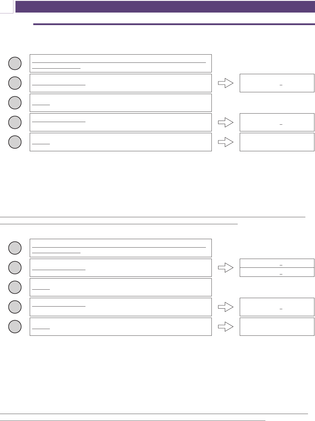
PROGRAM THE TCOO900 TO THE RCOO900P ACCORDING TO THE FOLLOWING INSTRUCTIONS:
PROGRAMMING OF THE MOVABLE DEVICE ON CHANNEL 1 OUTPUT OF THE FIXED DEVICE
To enter more TCOO900 in the RCOO900P, repeat the operation from step 2. (on page 3)
(*) If you hear 4 BEEPS, it means that the maximum number of safety edges for the selected channel has been reached
and that no new devices on the same channel output can be memorized.
NOTE: When the TCOO900 is used with two connected safety edges, it is necessary to carry out the learning process
two times, one for each input.
WARNING: The same output of the TCOO900 can be memorized on both output channels. To erase the memo-
rized input it is necessary to perform a complete reset of the RCOO900P (see page 8).
To enter more TCOO900 in the RCOO900P, repeat the operation from step 2. (on page 3)
(*) If you hear 4 BEEPS, it means that the maximum number of safety edges for the selected channel has been reached
and that no new devices on the same channel output can be memorized.
NOTE: When the TCOO900 is used with two connected safety edges, it is necessary to carry out the learning process
two times, one for each input.
WARNING: The same output of the TCOO900 can be memorized on both RCOO900P output channels. To erase
the memorized input it is necessary to perform a complete reset of the RCOO900P (see page 8).
1Check that the DIP 2 and 3 of the TCOO900 and DIP 3 and 4 of the RCOO900P
are set the same way.
2Press and keep pressed the programming/ reset button on the RCOO900P. RCOO900P emits 1 BEEP.
3Release the programming/reset button on the RCOO900P
4Press and keep pressed the programming/reset button on the TCOO900 relative to
the used input. Prog./Test1 for safety edge 1, Prog/Test2 for safety edge 2. RCOO900P emits 2 BEEPS. (*)
5Release the programming/reset button on the TCOO900. Programming has succeeded
PROGRAMMING
C
1Check that the DIP 4 and 5 of the TCOO900 and DIP 3 and 4 of the RCOO900P
are set the same way.
2Press and keep pressed the programming/ reset button on the RCOO900P.
RCOO900P emits 1 BEEP.
RCOO900P emits 2 BEEPS.
3Release the programming/reset button on the RCOO900P
4Press and keep pressed the programming/reset button on the TCOO900 relative to
the used input. Prog./Test1 for safety edge 1, Prog/Test2 for safety edge 2. RCOO900P emits 2 BEEPS. (*)
5Release the programming/reset button on the TCOO900. Programming has succeeded
PROGRAMMING OF THE TRANSMITTER ON CHANNEL 2 OUTPUT OF THE FIXED DEVICE
8
STEP 11
STEP 12
TEST THAT THE PROGRAMMING OF THE MOVABLE DEVICE WAS SUCCESSFUL.
On each TCOO900, two buttons, labeled “programming/test key”, and two leds are present. Pushing the programming
button of the edge to test during normal functioning (so not in programming) produces a signal that is sent to the
RCOO900P activates the output channel and responds to this signal with:
NOTE: If one TCOO900 is in the alarm state and it is necessary to open or close the operating device, press
and keep pressed the programming / test button of the TCOO900 in alarm at the same time the operating
device is activated to open or close.
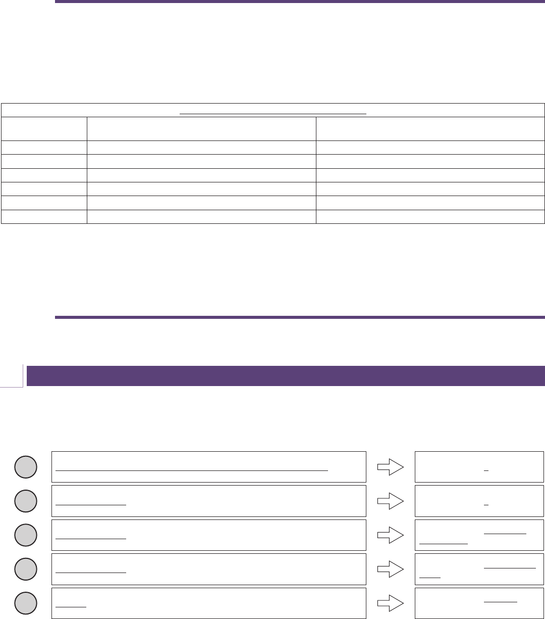
VERIFY THE CORRECT FUNCTION OF EACH SAFETY EDGE, MOVABLE AND FIXED DEVICES WITH
THE OPERATOR INSTALLED.
Using the program/reset key, it is possible to erase all TCOO900 that are programmed into the RCOO900P.
NOTE: This proceedure resets all memory to factory defaults.
Acoustic signaling during the normal functioning
Number of BEEP/
BLINK
Meaning What to do
1 Regular functioning, no mistake found. -
2 One or more safety edges faulty. Check the safety edge connections
3 One or more 8.2k / 10k resistive edges disconnected. Check the resistive edges connected
4 Battery level low. Substitute the batteries of the indicted device
5 Low battery. Replace the batteries
6 One or more associated devices disconnected Check each associated device
RECEIVER RESET
D
1Press and keep pressed the programming / reset button on the RCOO900P. RCOO900P emits 1 BEEP
2DO NOT RELEASE the programming/reset button on the RCOO900P. RCOO900P emits 2 BEEPS
3DO NOT RELEASE the programming/reset button on the RCOO900P. RCOO900P emits a series of
rapid BEEPS.
4DO NOT RELEASE the programming/reset button on the RCOO900P. RCOO900P emits a continuous
BEEP
5Release the programming/reset button on the RCOO900P RCOO900P emits 6 BEEPS. The
reset is complete.

9
With the dip switch set to low power it is important to remember that the TCOO900 will only check in with the
RCOO900P every 15 seconds. If a power failure (dead battery) were to occur during this 15 second interval,
the RCOO900P will only signal an alarm after the 15 second interval has been reached.
TCOO900 Dip switch 1 set ON: (Low power activated) state of the transmitter is checked every 15 seconds.
TCOO900 Dip switch 1 set OFF: (Low power deactivated) state of the transmitter is checked each second.
FCC ID: SU7TCO900 and SU7RCOO900P
This device complies with part 15 of the fcc rules. Operation is subject to the following two conditions: (1) this device
may not cause harmful interference, and (2) this device must accept any interference received, including interference that
may cause undesired operation.
IMPORTANT! Any changes or modifications not expressly approved by the party responsible for compliance could void
the user’s authority to operate this equipment.
ENERGY SAVING (LOW POWER)
E
FCC COMPLIANCE
F
FCC Radiation Exposure Statement
This equipment complies with FCC RF radiation exposure limits set forth for an uncontrolled environment. This equipment
should be installed and operated with a minimum distance of 20 centimeters between the radiator and your body.
This transmitter must not be co-located or operating in conjunction with any other antenna or transmitter.
The antennas used for this transmitter must be installed to provide a separation distance of at least 20 cm from all persons
and must not be co-located or operating in conjunction with any other antenna or transmitter.

10
1 – Ensure that wire leads from safety edge are securely attached to the movable device (TCOO900).
NOTE: Wire leads from safety edge have no specific polarity and can be placed in either terminal of Safety
device Input1 or Safety device Input2 on the movable device.
Ensure that wire leads into the fixed device (RCOO900P) are firmly connected and into proper terminals (ie
N.C. or N.O.) for help in wiring RCOO900P inputs see STEP 7 examples.
2 – Make sure that the type of safety edge attached to the TCOO900 is resistive.
How to determine the type of edge if there is no clear label:
A voltmeter can be used to determine the type of edge:
1- Set voltmeter to read Ohms
2- Place a test probe on each of the wire leads from the safety edge
3- If the voltmeter registers resistance (ie 8.2KΩ or 10KΩ) the safety edge is resistive
4- If the voltmeter does not register resistance (ie 1) the safety edge is mechanical
If safety edge is mechanical, the system RCOO900P / TCOO900 is NOT compatible.
Determine what type of output signal the gate operator is looking for:
•Doorking – 10K resistive device
•NICE – 8.2K resistive device
•If 8.2k or 10k (resistive): DIP switch 5 or 6 on the RCOO900P need to be in the ON position (DIP 5 for
Output1 and Safety Device 1 and DIP 6 for Output2 and Safety Device 2)
•If N.O. contact: DIP switch 5 or 6 on the RCOO900P needs to be in the o position (DIP 5 for Output1 and
Safety Device 1 and DIP 6 for Output2 and Safety Device 2)
3 – To ensure that the TCOO900 and RCOO900P are communicating within the same frequency DIP
switch 2 and 3 on the TCOO900 and DIP switch 3 and 4 on the RCOO900P need to be in the same
position.
4 – Check batteries in TCOO900 to ensure correct polarity and sucient power.
5 – If TCOO900 and RCOO900P are still not communicating ensure that obstacles between the devices
are moved and mount devices as high as possible and away from metal objects.
TROUBLESHOOTING
G
11
WARRANTY
The warranty period of this product is 24 months, beginning from the manufacturing date. During this period, if the product
does not operate correctly, due to a defective component, the product will be repaired or replaced at the sole discretion of
Transmitter Solutions. This warranty does not extend to the product casing which can be damaged by conditions outside of
the control of Transmitter Solutions.
EXCEPT AS SET FORTH ABOVE, TRANSMITTER SOLUTIONS MAKES NO WARRANTIES REGARDING THE GOODS, EXPRESS OR IMPLIED,
INCLUDING WARRANTY OF MERCHANTABILITY OR WARRANTY OF FITNESS FOR A PARTICULAR PURPOSE. BUYER MAKES NO RELIANCE ON ANY
REPRESENTATION OF TRANSMITTER SOLUTIONS, EXPRESS OR IMPLIED, WITH REGARD TO THE GOODS AND ACCEPTS THEM “AS-IS/WHERE-IS”.
TRANSMITTER SOLUTIONS SELLS THE GOODS TO BUYER ON CONDITION THAT TRANSMITTER SOLUTIONS WILL HAVE NO LIABILITY OF ANY KIND
AS A RESULT OF THE SALE. BUYER AGREES THAT TRANSMITTER SOLUTIONS SHALL HAVE NO LIABILITY FOR DAMAGES OF ANY KIND, WHETHER
DIRECT, INCIDENTAL OR CONSEQUENTIAL DAMAGES, INCLUDING INJURIES TO PERSONS OR PROPERTY, TO BUYER, ITS EMPLOYEES OR AGENTS,
AS A RESULT OF THE SALE. BUYER ALSO AGREES TO HOLD TRANSMITTER SOLUTIONS HARMLESS FROM ANY CLAIMS BUYER, OR ANY THIRD
PARTY, MAY HAVE AS A RESULT OF BUYER’S USE OR DISPOSAL OF THE GOODS. BUYER HAS READ THIS DISCLAIMER AND AGREES WITH ITS TERMS
IN CONSIDERATION OF RECEIVING THE GOODS.

2 480 South 3850 West, Suite
Salt Lake City, UT 84120
(866) 975-0101 • (866) 975-0404 fa
www.transmittersolutions.com