Controlled Entry Distributors SAM1000 ACCESS CONTROLS User Manual
Controlled Entry Distributors, Inc. ACCESS CONTROLS
UserManual.wiki
>
Controlled Entry Distributors
>
SAM1000 User Manual
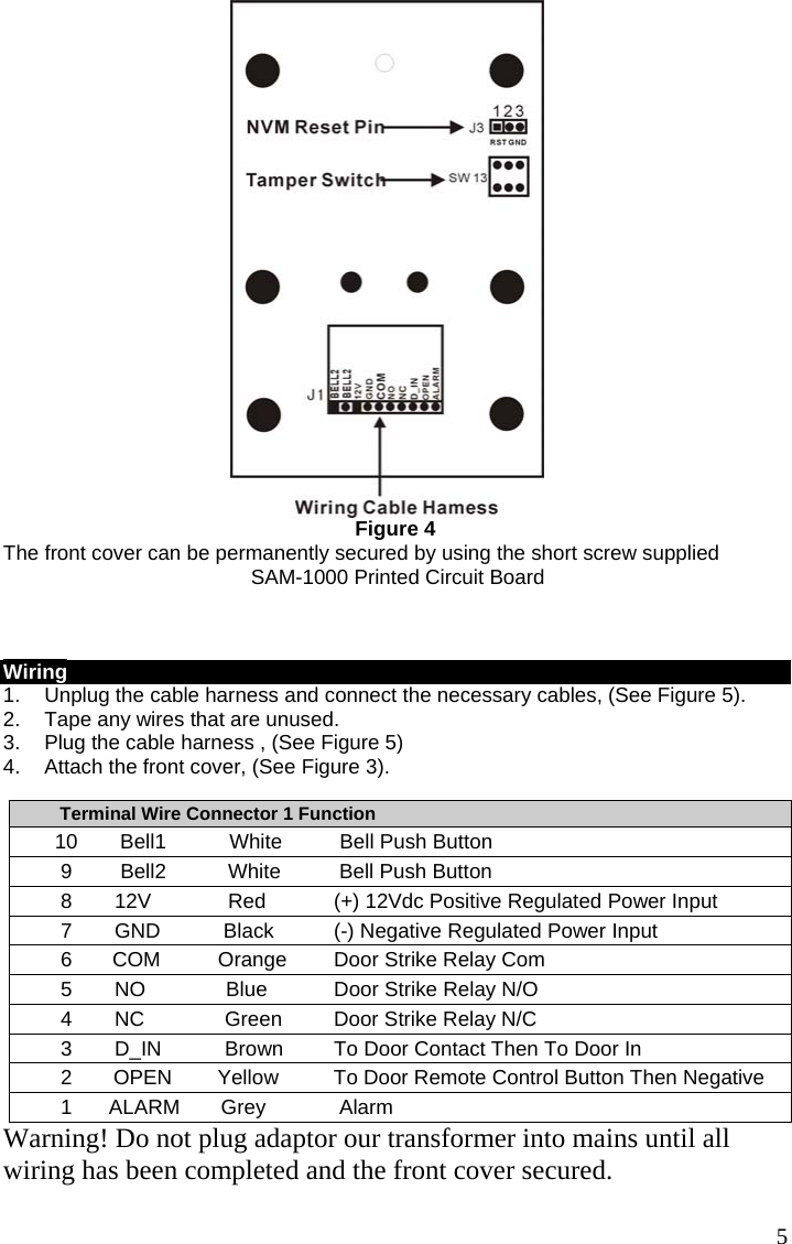
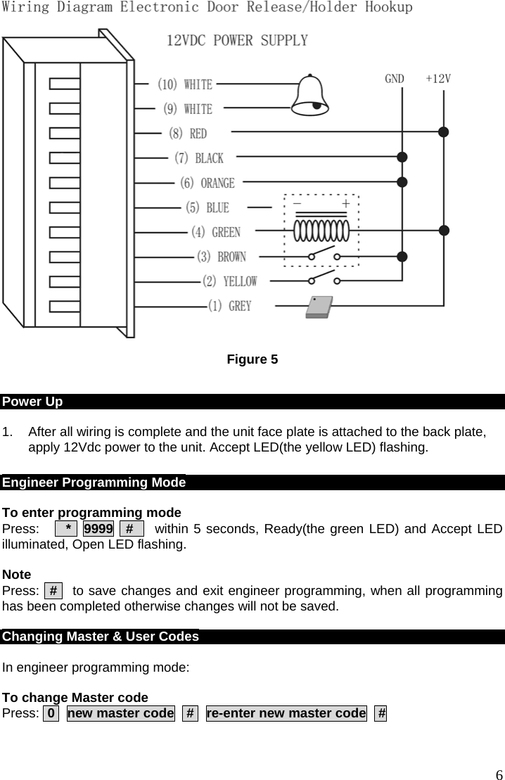
USERS MANUAL
Navigation menu
Upload a User Manual
Namespaces
Wiki Guide
HTML
PDF
Info
Views
User Manual
Discussion / Help
Navigation