Cooltrax Asia Pacific CTRX-UB-T2 RFID Tag User Manual
Cooltrax Asia Pacific Pty Ltd RFID Tag
user manual

Version1.1 September2008

CoolTraxUMDV2InstallationManual September2008
Page2of23
THIS DEVICE COMPLIES WITH PART 15 OF THE FCC RULES. OPERATION IS SUBJECT TO THE FOLLOWING
TWO CONDITIONS.
(1) THIS DEVICE MAY NOT CAUSE HARMFUL INTERFERENCE, AND (2) THIS DEVICE MUST ACCEPT ANY
INTERFERENCE RECEIVED, INCLUDING INTERFERENCE THAT MAY CAUSE UNDESIRED OPERATION.
Warning: Changes or modifications not expressly approved by the party responsible for compliance could
void the user’s authority to operate this equipment.
Note: This equipment has been tested and found to comply with the limits for a Class B digital device,
pursuant to part 15 of the FCC Rules. These limits are designed to provide reasonable protection against
harmful interference in a residential installation. This equipment generates uses and can radiate radio
frequency energy and, if not installed and used in accordance with the instructions, may cause harmful
interference to radio communications.
However, there is no guarantee that interference will not occur in a particular installation. If this
equipment does cause harmful interference to radio or television reception, which can be determined by
turning the equipment off and on, the user is encouraged to try to correct the interference by one or more
of the following measures:
—Reorient or relocate the receiving antenna.
—Increase the separation between the equipment and receiver.
—Connect the equipment into an outlet on a circuit different from that to which the receiver is connected.
—Consult the dealer or an experienced radio/TV technician for help.

CoolTraxUMDV2InstallationManual September2008
Page3of23
TableofContents:
TableofContents:...................................................................................................................................................3
UMDInstallationV2RF:ThermoKing....................................................................................................................4
StandardSystemKitofParts:.............................................................................................................................4
SystemInstallationInitialSetup:........................................................................................................................5
FirstStep–InstallAntenna’s:.............................................................................................................................5
DualBandGSM/GPSAntenna:.......................................................................................................................5
RFAntenna:.....................................................................................................................................................7
RFAntennaInstallation–PhysicalLocationInsidetheTrailer:......................................................................9
RFAntennaInstallation–PhysicalLocationoutsidetheTrailerBox:............................................................9
ThermoKingI‐BoxandLoomAssembly:..........................................................................................................12
TKuP1VoruPVoruPV1I‐Boxinstallation:......................................................................................................12
FromtheBatteryCompartmentSideoftheControllerCabinet:.................................................................13
TKSR2I‐Boxinstallation:..................................................................................................................................14
UMD/FridgeCommsCable:............................................................................................................................15
UMDtoi‐BOXConnection:...............................................................................................................................16
DiagnosticTests:...............................................................................................................................................16
SystemTest:......................................................................................................................................................17
Boot‐UpSequence:...........................................................................................................................................17
WirelessTagInstallation:..................................................................................................................................18
CoolTraxWirelessTemperatureTag:...........................................................................................................18
CoolTraxWirelessDoorTagandMagnet:....................................................................................................19
PostInstallation:...............................................................................................................................................20
UMDSpecifications:..........................................................................................................................................21
RFTagSpecifications:........................................................................................................................................22
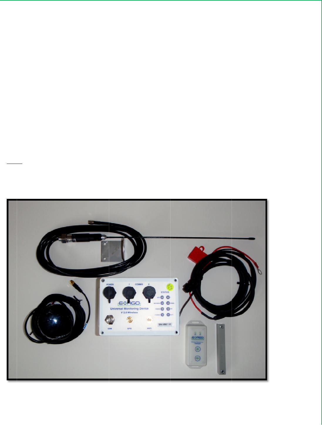
Co
o
U
M
St
a
Wit
No
t
trai
l
Pic
t
o
lTraxUMD
M
DI
n
a
ndardS
y
1. Uni
v
2. On
e
3. RF
T
4. RF
D
5. RF
T
6. On
e
htheTher
m
1. On
e
2. On
e
t
e:Ensure
t
l
er,therea
r
t
ure1:UM
D
V2Installa
t
n
stall
a
y
stemKi
t
v
ersalMon
e
DualBan
d
T
emperatu
r
D
oorTaga
n
T
ruckMou
n
e
1.5MUM
D
m
oKingFri
d
e
ThermoK
i
e
1.5MFrid
g
t
hattheI‐B
o
r
etwotyp
e
D
SystemKi
t
t
ionManu
a
a
tion
V
t
ofPart
s
itoringDev
d
Antenna
w
r
eTags–if
r
n
dMagnet
–
n
tAntenna
D
PowerCa
d
geinterfa
c
i
ngI‐Boxw
i
g
eComms
C
o
xkitisthe
e
sofTKi‐B
o
t
a
l
V
2R
F
s
:
ice(UMD).
w
ithco‐axia
r
equiredb
y
–
ifrequire
d
ble.
c
ethefollo
w
i
thinstallat
C
able.
correctty
p
o
xes–SR2
C
Page4of
F
:The
r
lcablesatt
a
y
thecusto
m
d
bythecu
s
w
ingadditi
o
ionkit.Thi
s
p
efortheT
C
ompatible
23
r
mo
K
a
ched.
m
er
s
tomer
o
nalcomp
o
s
itemisto
b
hermoKin
g
andµP1V,
K
ing.
o
nentsare
r
b
esupplie
d
g
Fridgeco
n
V&V1co
m
r
equired.
d
byTherm
o
n
trollerdep
l
m
patible.
Septemb
o
King(TK).
l
oyedonth
er2008
e
CoolTraxUMDV2InstallationManual September2008
Page5of23
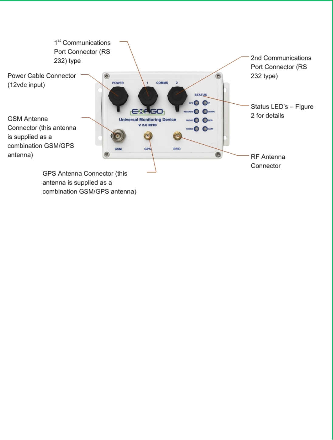
Picture2:UMDConnections
SystemInstallation
InitialSetup:
1. Openthefrontenginebayaccessdoors
2. OpenRHelectronicscompartmentaccessdoor
3. TurnOFFthemaintoggleswitchonthesideorfrontoftheTKControllercabinet–ensurethe
fridgeisinOFFMode.
4. DisconnectTKRefrigerationSystemBattery.IfafridgeinterfaceistobeinstalledANDthefridge
controllerisauPIV,uPVoruPVIthesystembatterymustberemoved.
5. OpentheTKelectronicsenclosuredoor.
FirstStep–InstallAntenna’s:
DualBandGSM/GPSAntenna:
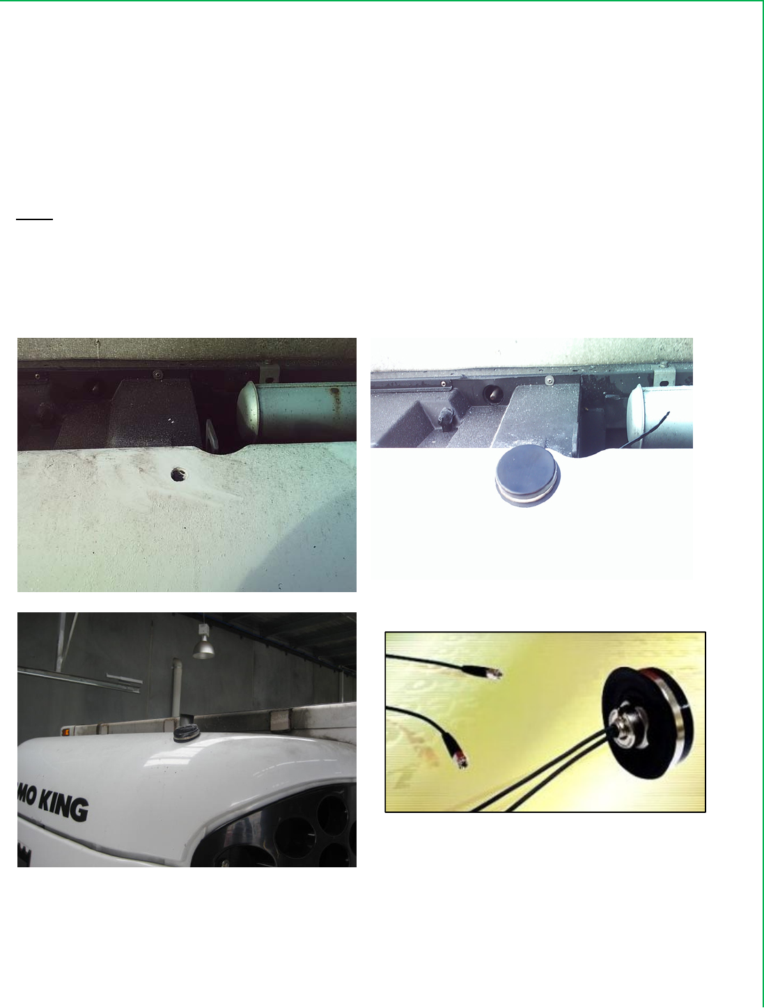
1. LocatetheDualBandUMDAntennaontopofthefiberglasscanopydirectlyabovetheheadertank
andapproximately40mminfromthebackedge.
2. Drilla13mmor0.5”holethroughthecanopy.
3. Feedthetwoseparatelengthsofantennacableinto20mmconvolutedtubingforprotection
4. Removethesplitnutfromtheundersideoftheantenna.
5. Fromthetopside,lowerthetwoco‐axialcablesfullythroughthedrilledhole.
CoolTraxUMDV2InstallationManual September2008
Page6of23
6. Fromtheundersideofthecanopy,placethesplitnutoverboththeco‐axialcableswiththeserrated
sideup,spinontothethreadedantennashaftandfirmlytighten.
7. Cabletietheco‐axialcablestotheTKsystem’swiringharnessorfixedhardwarethatdoesnotget
hot.
8. Loopandsecuretheexcessco‐axialcableintheUMDcavityandconnectandfingertightentheco‐
axialconnectorstotheUMD.
Note:
IftheUMDisinstalledinsidetheControllerBoxthentheantennacablescanbefedthroughtheexistingcable
hole/glandatthebackandbottomoftheControllerboxorelseaholecanbedrilledinthesideofthebox.
Picture4:GSM/GPSAntennaLocation
1/2”HoledrilledinFridgeUnitCanopy GSM/GPSAntennaInstalled
GSM/GPSAntennaInstalled–sideshot DualGSM/GPSor3GAntenna
CoolTraxUMDV2InstallationManual September2008
Page7of23
Picture4:UMDCableOptionsforUMDinstalledinControllerBox:
HoledrilledinsideofControllerBoxforUMD
Cables
ExistingCableHole/Glandinbottomof
ControllerBoxwhichcanbeusedforUMD
Cables
RFAntenna:
TheRFantennashouldbemountedinsidetherefrigeratedtrailer(the“box”)foroptimalresultswhen
receivingdatafromRFtemperatureordoortagslocatedwithinthetrailer.Ifthecustomerconfigurationisfor
fridgeinterfaceonlywithNOinternalRFTagsthentheAntennacanbelocatedontheoutsideofthetrailer
BUTwithinthefridgeunitsoitcan’tbeseenoreasilyaccessed/tamperedwith.
InternalRFAntenna:
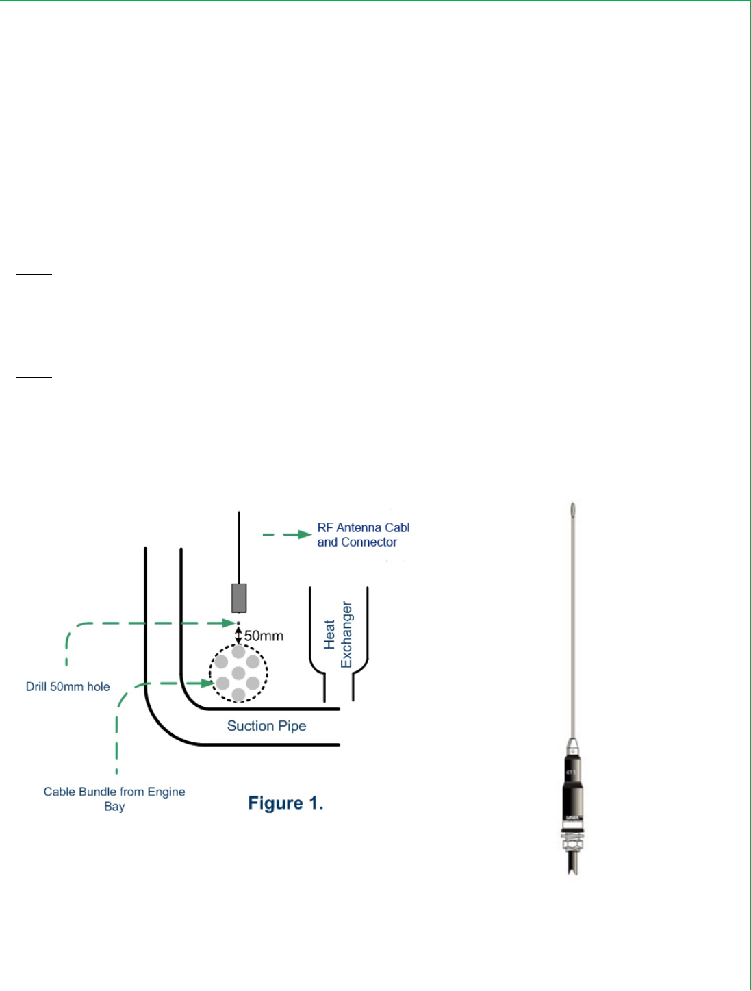
1. Fromtheenginebayside,locatethecablebundlethatgoesthroughthefirewallfromthediesel/
compressorcompartmenttotherefrigeratedcompartment.Ensurethatthearea50mmabove
thecablebundleisclearofcablesandenginebayhardware.Thecablesfromtherefrigerated
areawillentertheenginebaythrougha25mmholetobedrilledthroughthefirewallinthisarea.
Thisareamustbeclearedforthedrillingprocesssothatloomsorhardwarewithintheengine
bayarenotdamagedshouldthedrillbitentertheenginebay.
2. Fromwithintherefrigeratedarea,removethebulkheadsandevaporatorpaneltoexposethe
primaryevaporator.
3. LocatethecableloomtotheLHSoftheevaporatornearthelowerendoftheheatexchangerand
thebottomLHcornerofthesuctionpipe.RefFig1below
4. Markapointonthefirewallapproximately50mmabovethecableloomandinbetweentheheat
exchangerandthesuctionpipe.
5. Drillasmallpilotholethroughthefirewallandensuretheloomandhardwareclearancefromthe
enginebaysideisadequate.
6. IfOK,enlargetheholeto25mm.
7. Removeanydrillswarffrombothsidesofthefirewall
CoolTraxUMDV2InstallationManual September2008
Page8of23
8. FeedthemountingplateontotheRFAntennaCableandtightenintoplaceusingthesupplied
lock‐nut.
9. Feedthelengthofantennacableinto20mmconvolutedtubingforprotection
10. FrominsidethetrailerfeedtheconnectorendoftheRFAntennathroughthepreparedhole
leavingsufficientcabletoreachthepreferredmountinglocationinsidethetrailer.
11. Loopandsecuretheexcessco‐axialcableinthecavityandconnectandfingertightentheco‐axial
RFconnectortotheUMD
12. Cabletietheantennacabletoexistingcablingorcomponentsthatdonotgethotnearthe
firewallholeanduptheevaporatorcavity.
Note:Onsometrailerbodiesitistoodifficulttoremovetheinternalbulkhead–thereareanumberof
variationswhichdifferfromManufacturertoManufacturer–inthiscasemeasureupasuitablelocationto
drillaholethroughfromthefrontwhichwillexitjusttotheleftoftheinternalbulkheadandfeedtheantenna
cablethroughasdescribedabove.
Note:
IftheUMDisinstalledinsidetheControllerBoxthentheantennacablecanbefedthroughtheexistingcable
hole/glandatthebackandbottomoftheControllerboxorelseaholecanbedrilledinthesideofthebox.
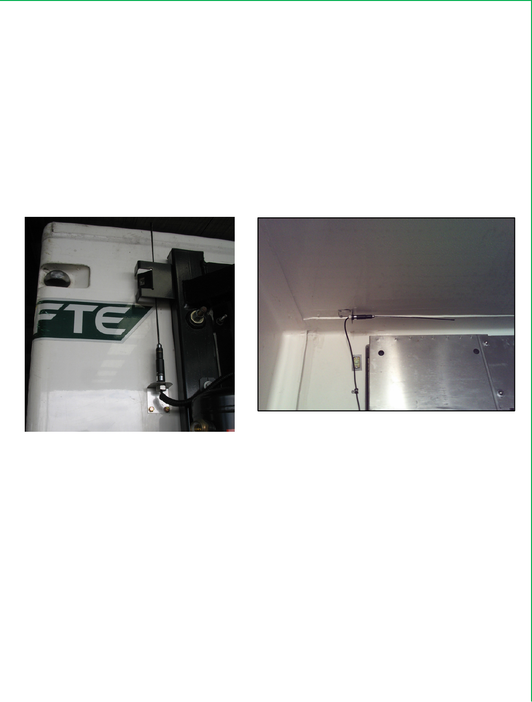
Figure1:DrillLocationforRFAntennaHolePicture5:RFTruckAntenna
CoolTraxUMDV2InstallationManual September2008
Page9of23
RFAntennaInstallation–PhysicalLocationInsidetheTrailer:
Foroptimalresultstheantennashouldbemountedtotheroofofthetrailerinahorizontalposition.Ensure
thattheantennaislocatedoutfromthebackwallasfaraspossiblebutwhereitisstillprotectedfrom
damagebytheinternalbulkheadofthefridgeunit–thisprovidesthebestopportunityfortheantennato
communicateconsistentlywithanytagslocatedinsidethetrailer.
WhereverpossibletheRFAntennashouldbelocated300mmawayfromanysteelsuchasfridgesupports,
internalbulk‐headsetc
UseP‐Clipstotidyupexcesscablingandfastentotheinternalwall.
Picture6:RFAntennaLocationinsidetheTrailerBox
RFAntennaLocationbehindtheSidePanel
oftheFridgeUnit
RFAntennaLocatedAboveInternalBulkhead–
HorizontalOrientation
RFAntennaInstallation–PhysicalLocationoutsidetheTrailerBox:
IftherearenoTagsinstalledwithinthetrailerthentheRFAntennacanbelocatedwithinthefridgeuniton
theoutsideofthetrailer.Theantennaisinstalledbehindoneofthesidepanelsofthefridgesothatitisoutof
sighttopreventunauthorizedaccessortamperingwiththesystem.Seebelowforasuggestedlocation.
Co
o
U
M
The
con
Pic
t
Po
w
o
lTraxUMD
M
DPowe
r
CoolTrax
P
nectorato
t
ure7:Coo
l
w
erCable
1.
Threa
d
tothe
UMD
s
2.
Coila
n
3.
Cable
t
harne
s
Note:
IftheUMD
hole/gland
andanten
n
Note:
Continuou
s
Picture8:
C
V2Installa
t
r
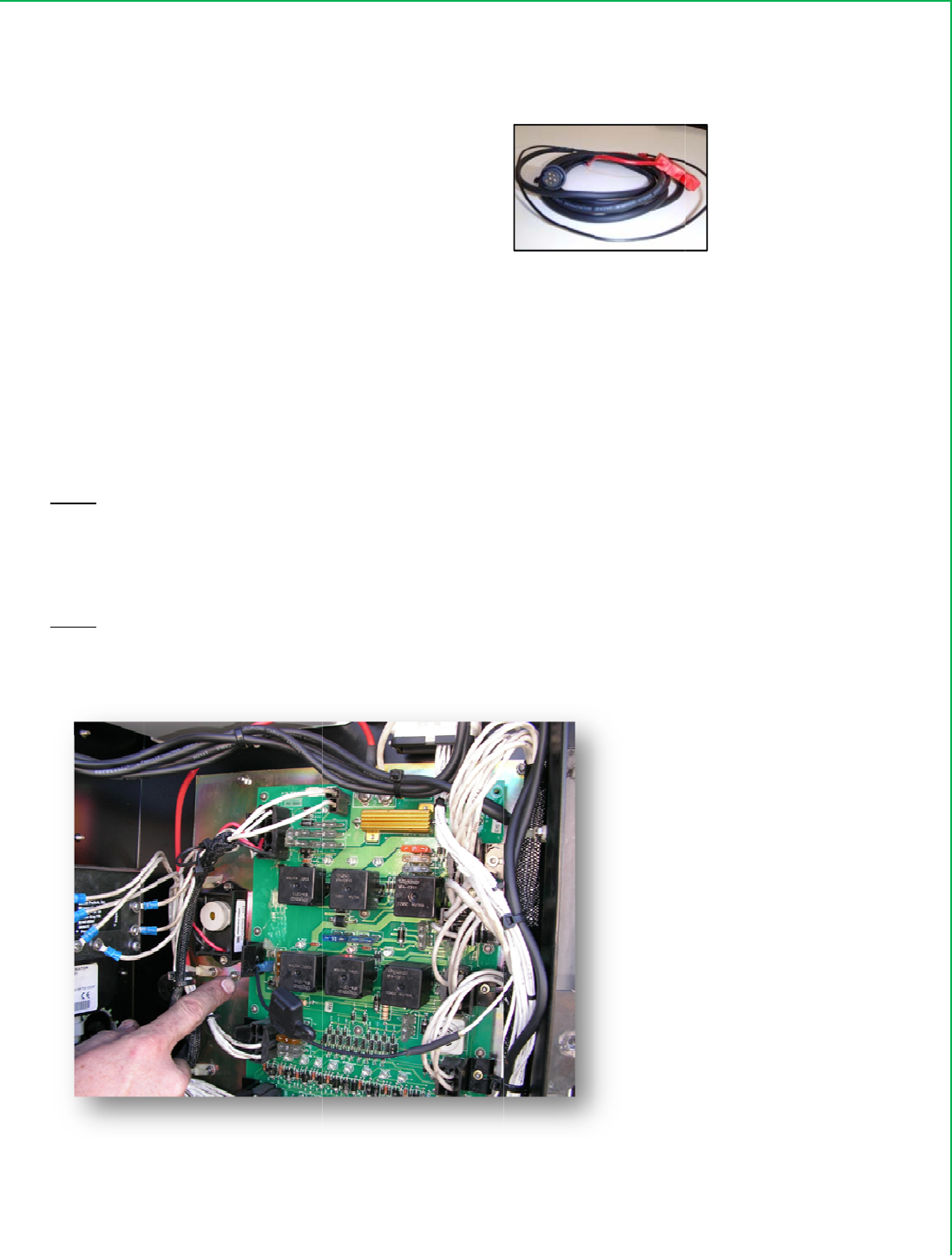
Cable:
P
owerCabl
e
neendand
l
TraxPowe
r
d
thepowe
r
UMD.
DO
N
s
othatther
e
n
dtiedown
t
ietheUM
D
s
sorfixed
h
isinstalled
atthebac
k
n
acables.
s
powerca
n
C
ontinuous
t
ionManu
a
e
comesco
m
eye‐conne
r
Cable
r
cableUM
D
N
OTCONN
E
e
willben
o
anyexcess
D
Powerca
b
h
ardwaret
h
insidethe
k
oftheCo
n
n
alsobeta
k
Powertak
e
a
l
m
pletewit
h
ctorsatth
e
D
connecto
r
E
CTTOTHE
o
tensiono
n
PowerCa
b
b
lefromth
e
h
atdoesno
t
Controller
B
n
trollerbox
k
enfromt
h
e
nfromCo
n
Page
10
o
f
h
a2Ain‐lin
e
other.
r
upfromt
h
UMD
atth
n
thecable
w
b
leLengthi
n
e
UMDare
a
t
gethot.
B
oxthent
h
orelseah
o
h
emotherb
o
n
trollerMo
t
f
23
efuse.The
h
ebattery
a
istimebut
w
henitisc
o
n
theUMD
a
downtot
h
epowerca
o
lecanbe
d
o
ardofthe
t
herboard
cableis1.
5
a
reabehin
d
leaveeno
u
o
nnected.
area.
hebattery
a
blecanbe
f
d
rilledinth
e
controller
5
Mlongan
d
d
alltheen
g
u
ghcablein
a
reaontot
f
edthroug
h
e
sidefort
h
rathertha
n
Septemb
d
hasa6‐Pi
n
g
inebayha
r
theareao
f
heexisting
h
theexisti
n
h
epowerc
a
n
fromthe
b
er2008
n
r
dware
f
the
wiring
n
gcable
a
ble
b
attery.
CoolTraxUMDV2InstallationManual September2008
Page11of23
InstallingtheUMD
IfyouarefittingtheUMDtoaSB310orlatermodelTKfridgetheUMDislocatedinsidethecontrollerbox
itself.
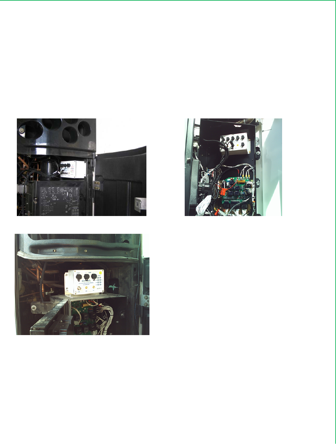
IfyouarefittingtheUMDtoaSpectrum,SL200/400EorearliermodelfridgetheUMDistypicallylocatedina
spaceimmediatelyabovethecontroller–seeimagesbelow.
Picture9:UMDInstallationLocation.
UMDLocatedAbovetheFridge
Controller–V2UMDinpicture
UMDLocatedinsidetheFridge
Controller‐V1UMDinpicture
UMDattachedtobracketontopof
ControllerBox‐V2UMDinpicture
ThemethodoffittingtheUMDdependsuponthefridgecontrollerandwhereyouchoosetolocateit,the
UMDcanbefixedtothecontrollerboxorfridgechassiswithanycombinationofthefollowing:
1. TheUMDcanbepop‐rivetedorscrewedtothechassisofthefridgeifitisinstalledinthegapabove
thefridgecontrollerbox

CoolTraxUMDV2InstallationManual September2008
Page12of23
2. TheUMDcanbepop‐riveteddirectlytotheinsideofthecontrollerboxitself–asseeninthesecond
pictureabove
3. TheUMDcanbeattachedtoamountingbracketandthebracketthensecuredtothetopofthe
controllerboxinthecaseofaSB400Installationorothers.
OncetheUMDisinstalledtheThermoKingi‐Boxcanbefitted.
ThermoKingIBoxandLoomAssembly:
ThisprocedureshouldbereadinconjunctionwiththeTKI‐Boxinstallationprocedure,whichformspartofthe
I‐Boxkit.ThereareatleasttwodifferenttypesofI‐BoxtosuitvarioustypesofTKcontrollers.
1. uPIVoruPVoruPVIorTGV1–TKPartNo#40‐816
2. SR2TKpartNo#40‐870
EnsuretheI‐BoxkitprovidedmatchestheTKControllertype.
MostTKcontrollershavetheoptionalDataAcquisitionSystem‘DAS’fitted.IftheDASisfitteditislocatedon
theinsidetopoftheTKcontrollerdoor.TheDASismountedonthreefixedstudswithitscableloomonthe
bottomface.ThisI‐Boxinstallationprocedureaddressesbothoptions,thatisTKControllerswithandwithout
theDASfitted.
TKuP1VoruPVoruPV1IBoxinstallation:
RefertoTKInstructionSheetforthe40‐816
IFATK‘DAS’BOXISALREADYFITTED:
1. Removethenyloknutsandwashers,whichsecuretheDASbox.
2. PulltheDASboxawayfromtheControllerdoorandletitgentlyhangbyitscableharness.
3. FittheI‐BoxoverthethreepanelstudswiththeI‐Boxconnectorfacingdownandfirmly
securewiththreetappedhexspacerssuppliedintheI‐Boxinstallationkit.
4. PlugintheI‐BoxcableharnesssuppliedintheI‐Boxinstallationkitandensureitsconnector
lockingclipengages.
5. PlaceDASboxoverthetopoftheI‐Boxonthethreehexspacersandsecureitwiththree
screws,plainandshake‐proofwasherssuppliedintheI‐Boxinstallationkit.
IFTHEREISNO‘DAS’BOXFITTED:
1. FittheI‐BoxoverthethreepanelstudswiththeI‐Boxconnectorfacingdownandfirmly
securewiththreeplainwashersandnyloknutssuppliedintheI‐Boxinstallationkit.
2. PlugintheI‐BoxcableharnesssuppliedintheI‐Boxinstallationkitandensureitsconnector
lockingclipengages.
I‐BOXWIRING:

CoolTraxUMDV2InstallationManual September2008
Page13of23
1. Connectthetwoblueeyeterminals,oncablesofsimilarlength,tothechassisterminalsin
thebottomrearoftheTKcontrollercabinet.
2. Connectthebackfusedleadtoswitched12Vfromthesystem’sON/OFFswitch.Ensurethe
leadisconnectedtotheoutputsideoftheswitch.
3. Pushthethreefemalecrimpedterminalsandthelongerblueeyeterminallead,jacketedin
theblackcablesleeving,throughthecabinet’smaincableentryportinthebottomrearof
thecabinet.Fromthebatterysideofthecabinetpulltheseleadsthroughuntiltheredtape
ontheloomjustappears.
4. Locatethethreeun‐terminatedwiresintheI‐Boxharnesslabeled‘TXD3,RXD3andCOM3’.
Stripapproximately4mmofinsulationfromthesewires.
5. Hardwirethei‐BoxHarnesswiresandtheUMDFridgeInterfacecableasfollows:
HARNESSWIRELABEL UMDFRIDGECOMMSCABLE
RXD3RedWire
TXD3White/ClearWire
COM3BlackWire
FromtheBatteryCompartmentSideoftheControllerCabinet:
1. Connecttheblueeyeterminaltothechassisconnectionabovethecableharnessexitfromthe
enclosure.
2. Threadthestrainreliefback‐shelloftheDeutschconnectorfromtheI‐Boxkitoverthewire
harnesswiththethreefemalecrimpedterminalswiththecablesupportbracketawayfromthe
femaleterminals.
3. Insertthethreefemaleterminalsintothe6wayDeutschconnectorfromtheI‐Boxkitfromthe
connectorrearandensuretheyapressedfullyhomeandlocked.Thesearetobeinsertedas
follows:
4. WIRELABELDEUTSCHCONNECTORLOCATION
5. TXD2 A
6. RXD2 B
7. COM2 C
8. Insertthethreeblanking/sealingpinsintotheunusedconnectorlocations,D,E&F
9. Screwthestrainreliefontotherearoftheconnectorandtighten.
10. Cabletiethethreewirecablebundletothestrainrelief.
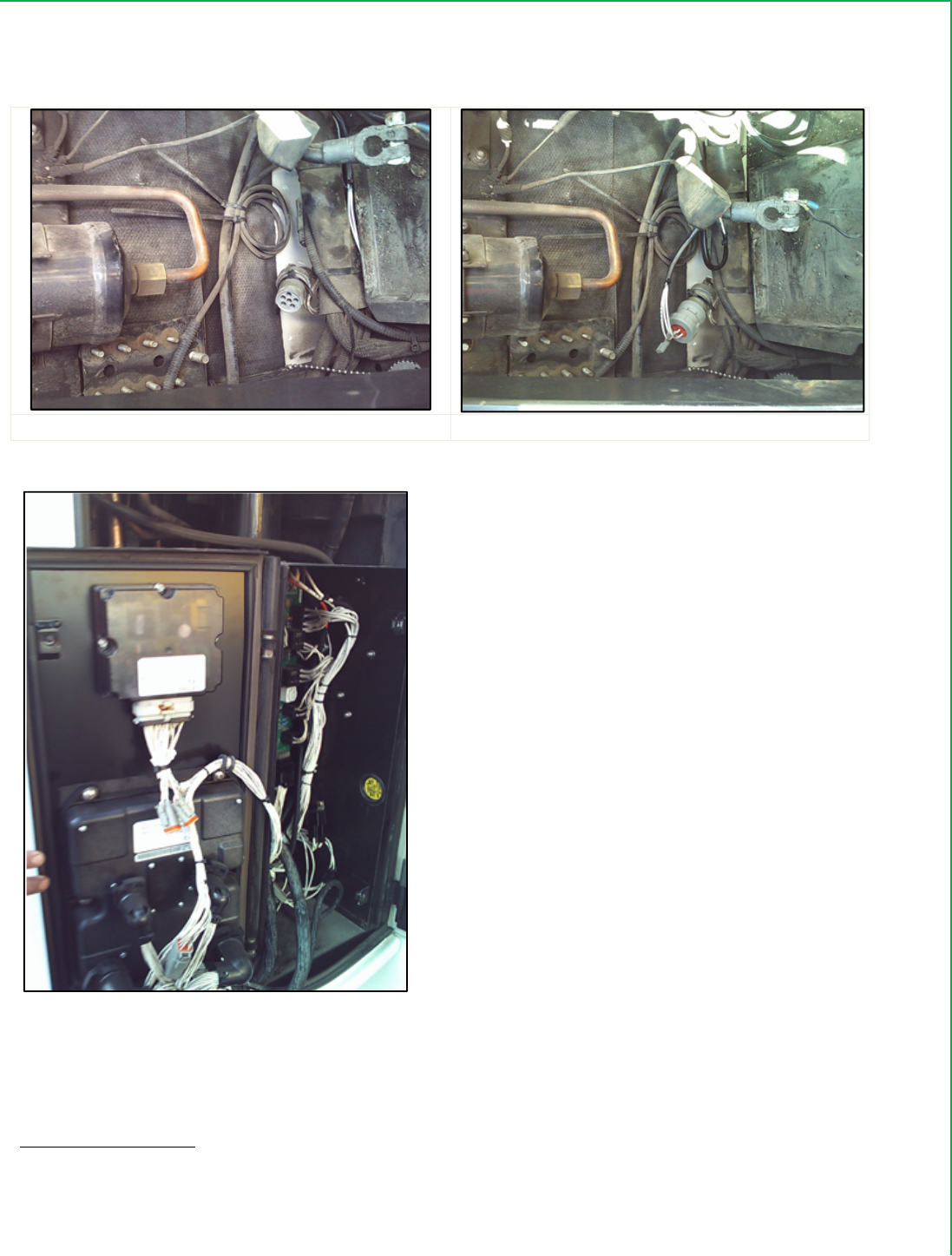
11. Locatetheunused6wayDeutschconnectorthatshouldbetieddownwiththecablebundle
thatrunsbehindthebatteryontheflooroftheenginebay.Thiscable/connectorassembly
shouldhaveasealingcapfitted.Removethecap.
12. ConnectandlocktheDeutschconnectorfromtheI‐Boxtothisconnector.
13. Stowthematedconnectorsandcabletietothemainwiringharness.
CoolTraxUMDV2InstallationManual September2008
Page14of23
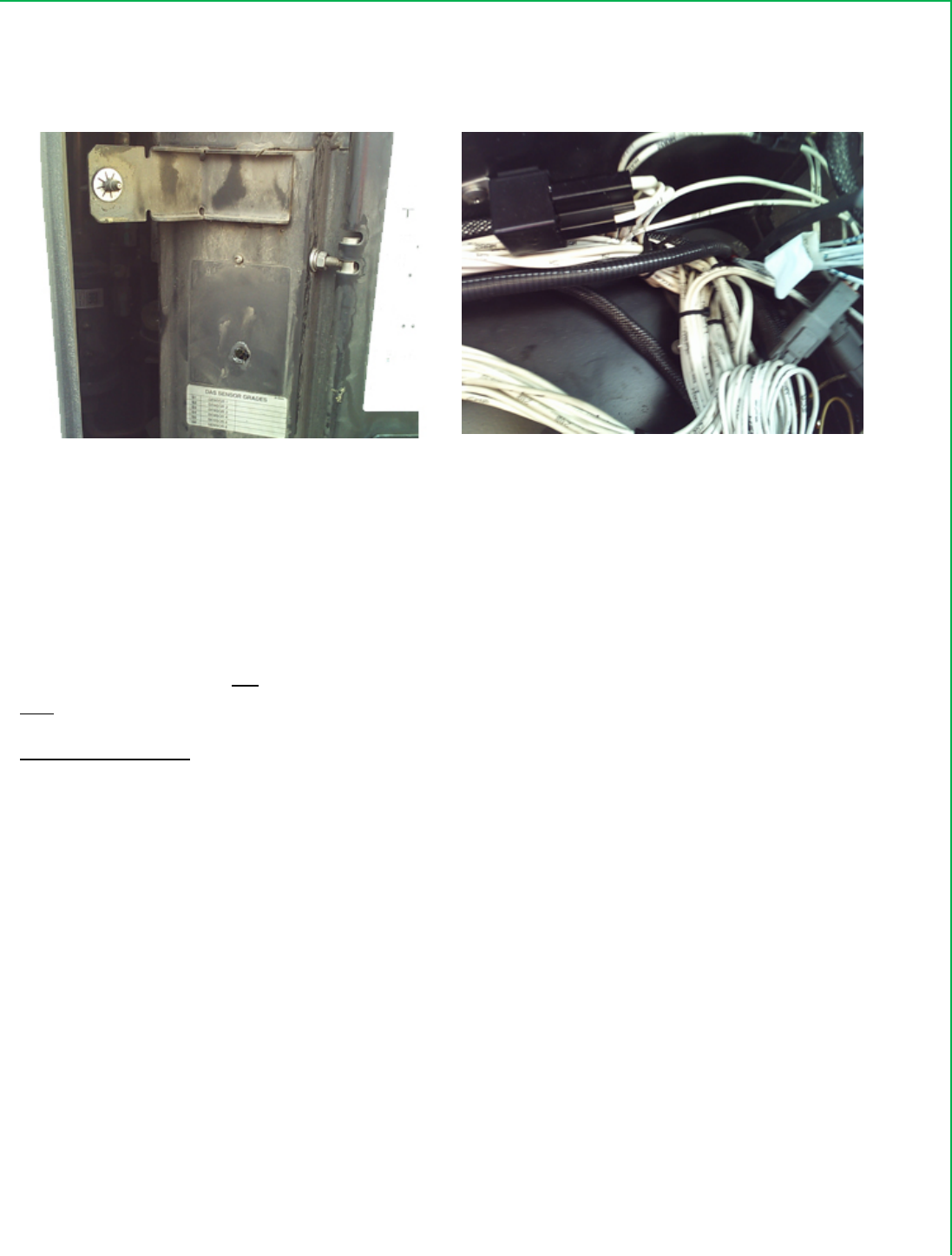
Picture10:i‐BoxConnectiontoDeutschConnector
DeutschConnectorlocatedbehindthebatteryi‐BoxconnectedtoDeutschConnector
Picture11:DAS
TKSR2IBoxinstallation:
RefertoTKInstructionSheetprovidedwiththe40‐870Kit.WiththeseunitstherewillnotbeaseparateDAS
boxfittedsothethreeinternalstudsonthecontrollercabinetdoorshouldbefree.
I‐BOXINSTALLATION:
CoolTraxUMDV2InstallationManual September2008
Page15of23
1. FittheI‐BoxoverthethreepanelstudswiththeI‐Boxconnectorfacingdownandfirmly
securewiththreeplainwashersandnyloknutssuppliedintheI‐Boxinstallationkit.
2. PlugintheI‐BoxcableharnesssuppliedintheI‐Boxinstallationkitandensureitsconnector
lockingclipengages.
I‐BOXWIRING:
1. CutoffthethreefemalecrimpedterminalsfromtheleadslabeledTXD2,RXD2andCOM2
andstripapproximately4mmofinsulationfromtheseleads.
2. Hardwirethei‐BoxHarnesswireswiththeUMDfridgeInterfacecablewiresasperthe
connectionsbelow
3. PushtheCOM2blueeyeterminalleadthroughthecabinet’smaincableentryportinthe
bottomrearofthecabinet.Fromthebatterysideofthecabinetpullthisleadthroughuntil
theredtapeonthewirejustappears.Connectthisleadtothechassisconnectionpointon
thefirewall,behindtheControllercabinet
4. Attachthe8pinconnectortotheconnectorlabeledJ12ontheTKControllerPCB.
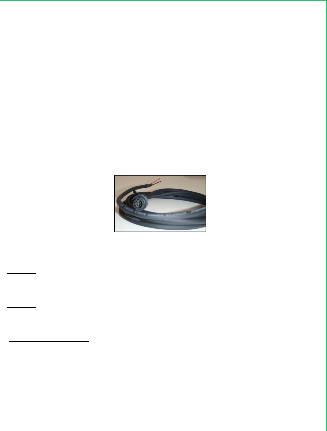
UMD/FridgeCommsCable:
Picture12:InterfaceCable
TheUMDFridgecommscablecanbeinstalledintwoways.
OPTION1:TheUMDFridgecommscablecanbeinstalledthroughthegrommetedholeinthebottomrearof
thecontrollercabinetifthereisroom.Thisisthepreferredoption.IfthereisnotroomtofittheUMDcomms
cableinthisarea,thesecondoptionmaybeused.
OPTION2:TheUMDFridgecommscablecanbeinstalledthroughanexistingholeinthesideoftheTK
ControllerCabinet.Thisholehasasealingpatchfittedoverit.Ifthisoptionisused,theholemustbere‐sealed
withsiliconeadhesiveaftertheUMDCommscablehasbeeninstalled.
OPTION1CableInstallation:
1. FeedtheUMDFridgeCommscablefromtheUMDdownthebackoftheTKControllercabinet
behindtheenginebayhardware.(InthesameareathattheotherUMDcableshavebeenrun.).
LeaveenoughcableintheUMDareasothatwhentheUMDCommsCableconnectorisconnectedto
theUMDthereisnotensiononthecableorconnector.
2. CabletietheUMDCommscableattherearoftheTKControllercabinet.

CoolTraxUMDV2InstallationManual September2008
Page16of23
3. Fromthebatterycompartmentside,gentlypushthethreeloosecrimpedmalepinsandcablebody
throughthegrommetedholeinthebottomrearortheTKControllercabinet.Pullanyexcesscable
lengthintotheTKControllercabinet.
OPTION2CableInstallation:
1. PushaholethroughthesealingpatchwheretheholeisintheTKControllercabinet(Ref.Fig.6.)
2. FeedtheUMDFridgeCommsacrossthetopoftheTKControllercabinet,downthesideandthrough
theformedhole.LeaveenoughcableintheUMDareasothatwhentheUMDCommsCable
connectorisconnectedtotheUMDthereisnotensiononthecableorconnector.
3. PullanyexcesscablelengthintotheTKControllercabinet.
4. Siliconesealaroundtheformedhole.
UMDtoiBOXConnection:
ForµP1V,VandV1i‐Boxes:
1. TheRxd3wireconnectstotheUMDscommscableredwire
2. TheTxd3wireconnectstotheUMDscommscablewhite/clearwire.
3. TheCom3connectstotheUMDscommscableblackwire.
ForSR2 i‐Boxes:
1. TheRXD2wiretotheUMDcableREDwire
2. TheTXD2wiretotheUMDcableWHITE/CLEARwire
3. TheCOM3wiretotheUMDcableBLACKwire
FinalStepstoConnectUMDandI‐BOX:
UnplugthedustcapontheUMD‘COMM1’connector
ConnecttheUMDFridgeCommsCabletothe‘COMM1’portontheUMD
DiagnosticTests:
Inallcases,aftertheseconnectionsaremadeandtheI‐boxandUMDareON,thefollowingvoltagesshouldbe
present.
• SetaDigitalMultiMetertoDCvolts
• Connectthemetersnegativeleadtothechassisandconnectthepositiveleadofthemultimeterto
UMDcableREDWire.Thisshouldread‐8to‐11Volts
• MovethemeterspositiveleadtotheUMDcableWHITE/CLEARwire.Thisshouldread0volts
• ThenmovethemeterspositiveleadtoRXD(x)fromtheThermoKingI‐Box.Thisshouldread0Volts(To
REDwireonUMD)
• ThenmovethemeterspositiveleadtotheTXD(x)fromtheThermoKingI‐Box.Thisshouldread‐8to‐
11Volts(toBlackwireonUMD)
CoolTraxUMDV2InstallationManual September2008
Page17of23
Makesurealltheleadsarefullyinsulatedandsupportedafterthecorrectconnectionsareverified.
SystemTest:
1. ChecktheEngineBayforanytools,fixingsoroff‐cuts,whichmayhavebeenleftbehind.
2. Installandre‐connectTKSystemBattery
3. TieallnewI‐BoxandUMDloomingwithintheTKControllerCabinet.
4. Un‐plugtheUMD‘POWER’connectordust‐capandconnecttheUMDPowerlead.
5. TurnONtheTKControllerusingthemain12VON/OFFswitchandbepreparedfortherefrigeration
systemtostart.
6. EnsurethattheREDledintheI‐BoxineitherauPoranSRapplicationisglowingasteadyRED.
7. ScrewclosedtheTKControllerCabinetDoor.
PleaseNote:AlwaysconnectthepowertotheUMDlast!
BootUpSequence:
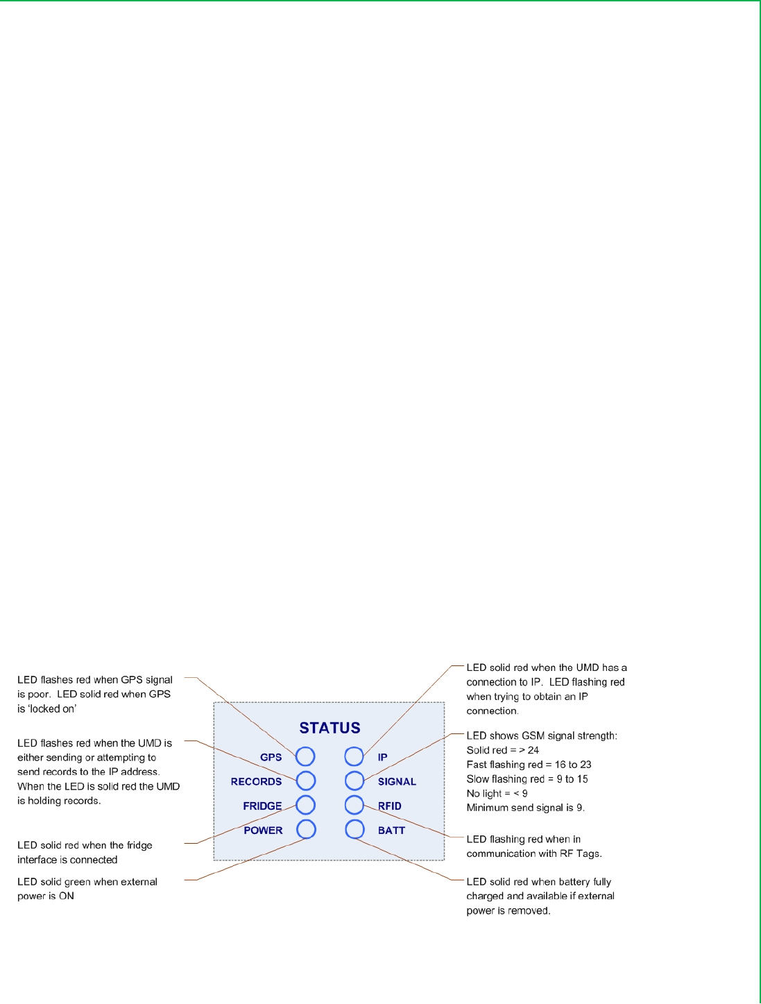
1. Withinapproximately30secondstheUMD‘Power’LEDwilllightupGREEN,followedcloselybythe
batterylight.
2. ShortlyaftertheSignalLEDwillbegintoflash,assumingthatthereisGPRSor3Gserviceavailableon
theGSM/3Gnetwork.
3. TheIPLEDwillatfirstflashandthenremaininaconstantONStateonceanIPconnectionhasbeen
established
4. TheGPSLEDwilllightupaconstantREDtoindicatethatGPShasbeenacquired–typicallyin30secs
orless.
5. IfRFTagshavebeeninstalledthentheRFLEDwillflasheveryfewsecondsasthetagscommunicate
withtheRFReadersectionoftheUMD
Picture13:UMDLED’s
Co
o
Wi
The
sav
e
rea
d
co
m
req
u
Pic
t
Co
o
Eac
h
the
Ch
e
trai
l
Im
p
wit
h
rep
o
Te
m
int
h
o
lTraxUMD
relessT
a
newRFID
U
e
sconsider
a
d
ingpoints
m
municate
w
u
irements.
t
ure14:Wi
r
W
o
lTrax
W
i
h
CoolTrax
T
trailerwall
e
ckwithCo
o
l
er.
p
ortantNo
t
h
andinstal
o
rttothat
U
m
perature
a
h
etrailers
n
V2Installa
t
a
gInstal
l
U
MDcom
m
a
bleinstall
a
inthetrail
e
w
ithourU
M
r
elessTem
p
W
irelessTe
m
i
relessT
e
T
aghasafl
ordoor.
o
lTraxorth
t
e:
TheRFI
D
ledwithth
e
U
MD.
a
ndDoorT
a
n
ormaldail
y
t
ionManu
a
l
ation:
m
unicates
w
a
tiontime.
e
roradoo
r
M
D,theset
a
p
eraturean
d
m
perature
e
mperatu
angedbas
e
ecustome
r
D
Tagssupp
e
specificU
a
gsneedto
y
operation
a
l
w
ithCoolTr
a
Dependin
g
r
openand
c
a
gsshould
d
DoorTag
s
Tag
reTag:
e
withhole
s
r
forinform
liedwitha
U
MD.IfRF
T
belocated
s–byfork‐
Page
18
o
f
a
xremotet
e
g
onthecu
s
c
losetaga
n
locatedby
t
s
s
toallowt
h
ationinre
s
U
MDares
p
T
agsfroma
n
inapositi
o
liftswhenl
f
23
e
mperatur
e
s
tomersde
s
n
dmagnet,
t
heinstalle
Wireles
s
h
einstaller
t
s
pecttowh
e
p
ecificfort
h
n
otherUM
D
o
nwithinth
oadingpall
e
e
anddoor
s
s
iretohav
e
CoolTraxp
raccording
s
DoorTag
a
t
oeithersc
e
rethetag
s
h
atparticul
D
Kitarein
s
etrailerw
h
e
tsetc.
s
ensorsvia
e
independ
e
rovidesRF
c
tothecus
t
a
ndMagne
t
reworpop
s
shouldbe
arUMDth
e
s
talledthey
h
eretheyw
Septemb
wireless;t
h
e
nttemper
c
apableta
g
t
omer’s
t
‐rivetthet
a
locatedin
e
e
ymustbe
willnotbe
illnotbed
a
er2008
h
is
ature
g
swhich
a
gto
e
ach
kept
ableto
a
maged
CoolTraxUMDV2InstallationManual September2008
Page19of23
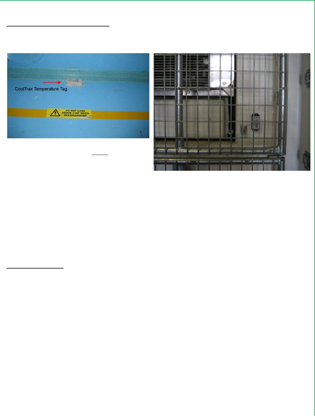
ExampleTemperatureTagLocations:
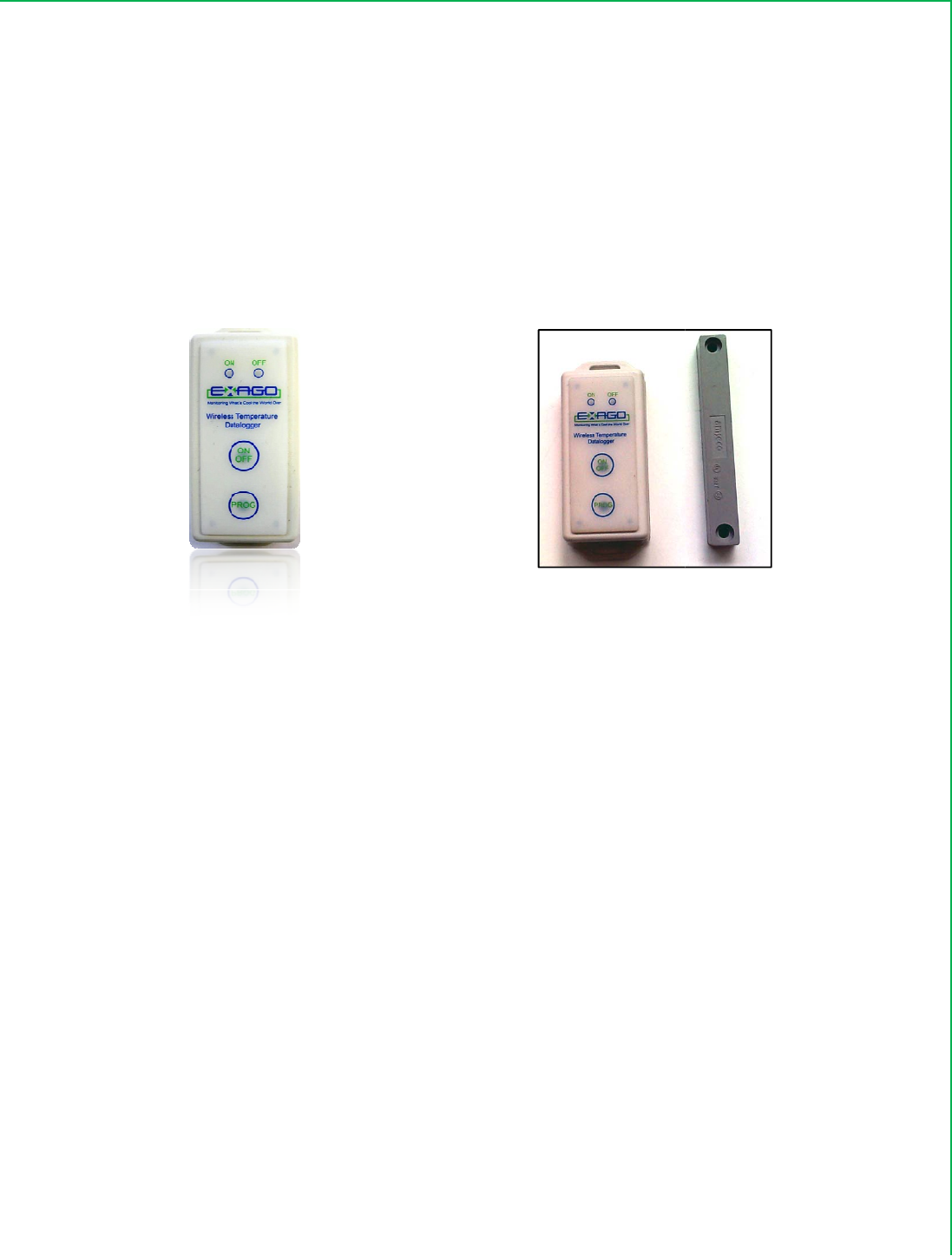
Picture15:WirelessTemperatureTags
TemperatureTaglocatedabovetheload
linealongthetrailerwall.
TemperatureTaglocatedbytheReturnAirduct
CoolTraxWirelessDoorTagandMagnet:
ThelocationoftheDoorTagsandMagnetwillvaryaccordingtothevariousbodytypesofthetrailerand
whetherthefitteddoorsarerollerorbarnstyle.Theimportantconsideration,again,istolocatetheTagand
Magnetinapositionwheretheywillnotbedamaged.Thisrequiresacarefulassessmentbytheinstallerona
casebycasebasisastherearesomanyvariationsfromtrailertotrailerandevenbetweenthedifferentdoor
types.
InstallationOptions:
1. OntheInsideoftheBarndoorswiththemagnetlocatedontheRHdoor(lookingfrominsidethetrailer
out
2. IftheTrailerbodyhasalipalongthetopattherearthenthetagcanbelocatedontheinsideofthatlip
whereitisprotectedandthemagnetattachedtoabracketontheinsideofthedoor
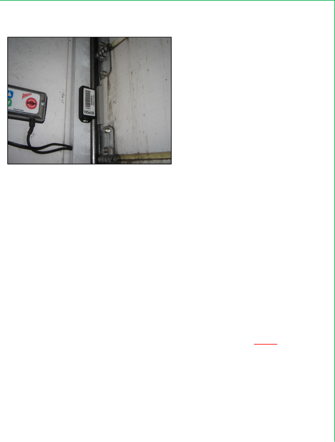
3. InthecaseofarollertypedoorthetagistypicallylocatedontheinsideLHsidewalldirectlyadjacent
totherollerdoorandthemagnetlocatedontherollerdooritself–checkingforclearancewhenthe
dooris“rolledup”.Seepicturebelow.
CoolTraxUMDV2InstallationManual September2008
Page20of23
Picture16:WirelessDoorTags
DoorTagfittedtoaRollerDoorInstallation DoorTagandMagnetfittedtoBarnDoor
PostInstallation:
OncethephysicalinstallationoftheunitiscompleteandtheUMDispoweredoncontactCoolTraxSupport
staffsothattheycancheckthattheunitisreportingasexpected.
OncontactprovidethefollowingInstallationDetails(viaphoneorfaxthecompletedInstallerTemplate
providedbyCoolTrax):
1. TheCustomerName
2. TheFleetIDoftheTrailer
3. TheUMDID(locatedonthefrontoftheUMD–typicallyUBXXXX
4. TheFridgeModel
5. TheSensorlocationwithSensorID–iffitted
6. Theinstallernameandcontactdetails–mobilephonenumbertocalloncetheunithasbeentested
PleaseensurethatCoolTraxstaffconfirmsthattheunitisreportingdataasexpectedBEFOREthetrailerleaves
theinstallerspremises.
CoolTraxstaffwillaskyoutoconductanumberoffridgeoperationsaspartoftheInstallationChecktomake
suretheunitfridgeinterfaceiscorrectlyinstalledandconfigured.
• PowerthefridgeunitonandofftochecktheFridgeInterfaceisfunctioningasexpected
• ChangeSetPointTemperature

CoolTraxUMDV2InstallationManual September2008
Page21of23
• OpenandClosetheRearDoortotestDoorTagiffitted.
CoolTraxSupportContacts:
AndrewWongYen–(613)96866011
JosephBortignon–(613)96866011
UMDSpecifications:
UMD Power Power Supply 12VDC to 48VDC
Average Power Consumption Less than 2W
Internal Fuse 2A (not field replaceable)
Discrete Type Closing contact
No of Channels 2
WiFi Interface Band 430 MHz UHF ISM
Transmit Power 10 dBm Max Burst Transmission
Receive Sensitivity -100 dBm typical
Range 50m typical in clear line of sight
Serial Data Comms Comm 1 RS-232
Data Rate 9600 Baud Standard -
configurable up to 38.4K Baud
by firmware
Function Typical use for fridge interface
Comm 2 RS-232
Data Rate 9600 Baud Standard -
configurable up to 38.4K Baud
by firmware
Function Typical use for firmware
upgrades
GPS Specifications subject to
available / visible satellites
Acquisition Time Power Up < 1min typical

CoolTraxUMDV2InstallationManual September2008
Page22of23
Re-acquisition < 1 sec typical
Accuracy Horizontal < 2.5 meters CEP
Enclosure Dimensions Length 2170 mm
Width 103 mm
Height 95 mm
Min height clearance 160 mm
Mounting Centers (4 by 5.0mm slot holes in base
flanges) Mountable in any attitude
Length 157 mm
Width 60 mm
Environmental Specifications Sealing IP65
Operational Temperature -30°C to +60°C (external)
RFTagSpecifications:
Tag Power Internal battery 3.6V lithium thionyl chloride
Average Power Consumption Less than 70 uW
Expected Life < 3 years
Range and Accuracy Temp measurement accuracy ±0.50C by calculation
Temp range -300C to +700C
Stabilisation period 4 hrs typical
Sample Rates and
Temperature Data Storage Sample send rate (temp mode) 20 secs average
Sample rate (consignment mode) 1 min to 4 hrs in 1 min increments
Temp data storage capacity
(consignment mode) 31,488 samples
Temp data upload rate 400 samples per sec
Range 50m typical in clear line of sight
WiFi Interface Band 430 MHz UHF ISM

CoolTraxUMDV2InstallationManual September2008
Page23of23
Transmit Power 10 dBm Max Burst Transmission
Receive Sensitivity -100 dBm typical
Range 50 m typical in clear line of sight
Enclosure Dimensions Length 97 mm
Width 40 mm
Height 22 mm
Mounting Centers (2 by 3.5mm by 13mm slot holes in
base flanges) Mountable in any attitude
subject to antenna requirements
Environmental Specifications Sealing Wet assembled
Operational Temperature -30°C to +70°C (external)