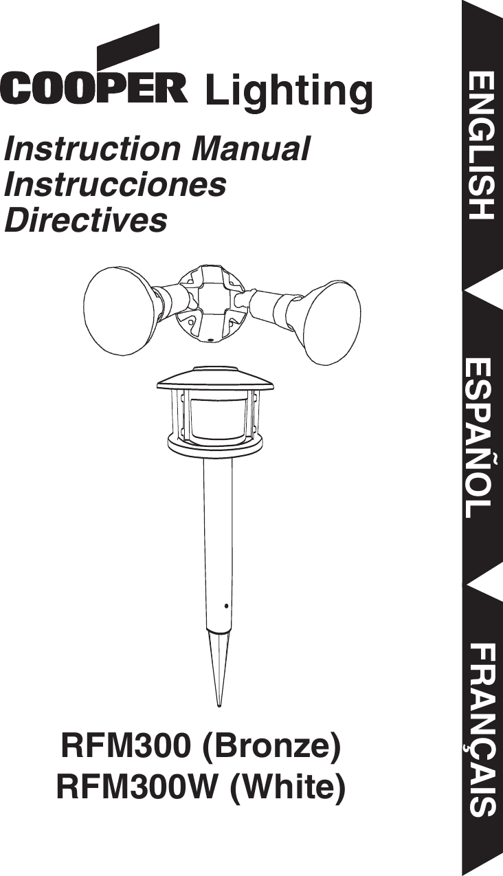
Cooper Lighting TS180DC PIR Transmitter User Manual RFM300 I S 325 XXXX

Cooper Lighting PIR Transmitter RFM300 I S 325 XXXX

User Manual

RFM300 (Bronze)RFM300W (White)ENGLISH ESPAÑOL FRANÇAISInstruction ManualInstruccionesDirectives
RFM300 (Bronze)RFM300W (White)Congratulations. You have just purchased a Cooper Lighting digital wirelesscommunication system. The battery operated landscape motion sensor con-tains a radio frequency (RF) transmitter. The twin par floodlight contains a RFreceiver and can be mounted to a standard junction box. When the sensordetects motion, it automatically sends a signal to the receiver, which turnson the floodlight.What you need• Phillips screwdriver • Electric drill• 1/8" drill bit• Outdoor weatherproof silicone caulking• (4) "AA" alkaline batteries • Safety Glasses• Hammer or malletWhat’s included• Battery operated landscape motion sensor (A)• (2) 6-32 Light fixture mounting screws (B)• Light fixture (receiver) (C)• Coverplate gasket (D)• (2) 8-32 Light fixture mounting screws (E)• Wire nuts (F)• (2) Floodlight bulbs (G)• Stainless steel post mounting screws (H)• Motion sensor post (I)• Motion sensor spike (J)What to knowPLEASE READ THESE IMPORTANT SAFETY INSTRUCTIONS.• For outdoor use only.• UL/cUL LISTED for wet locations.• Landscape motion sensor must be powered by (4) AA Alkaline Batteries(6VDC Rating)• Floodlight must be connected to a 120Volt, 60Hz power source. Any otherconnection voids warranty.2ENGLISHCall for customer service and/or missing or damaged parts (800-334-6871)ABCDEHIJFG
3ENGLISH• WARNING: Risk of fire/electric shock. This motion activated floodlightsystem, should be installed by persons with experience in householdwiring or by a qualified electrician. The electrical system, and the methodof electrically connecting the fixture to it, must be in accordance with theNational Electrical Code and local building codes. • WARNING: Risk of fire. If uncertain, consult an electrician. • Disassembly of your fixture will void the warranty.• Exercise care in handling the batteries in order not to short the batterywith conductive materials such as rings, bracelets and keys.  The batteryor conductor may overheat and cause burns.• Observe proper polarity orientation between the batteries and batterycompartment.• Do not mix old and new batteries or batteries of different sizes in this product.• This device complies with Part 15 of the FCC Rules. Operation is subjectto the following two conditions: (1) This device may not cause harmfulinterference, and (2) this device must accept any interference received,including interference that may cause undesired operation. Under Part 15of the FCC Rules, any changes or modifications to the motion detectordescribed in this instruction sheet that are not expressly approved byCooper Lighting could void the user’s authority to operate the equipment.NOTE: This equipment has been tested and found to comply with the lim-its for a Class B digital device, pursuant to part 15 of the FCC Rules.These limits are designed to provide reasonable protection against harm-ful interference in a residential installation.  This equipment generates,uses and can radiate radio frequency energy and if not installed and usedin accordance with the instructions, may cause harmful interference toradio communications.  However, there is no guarantee that interferencewill not occur in a particular installation.  If this equipment does causeharmful interference to radio or television reception, which can be deter-mined by turning the equipment off and on, the user is encouraged to tryto correct the interference by one or more of the following measures:• Reorient or relocate the receiving antenna.• Increase the separation between the equipment and receiver.• Connect the equipment into an outlet on a circuit different from that towhich the receiver is connected.• Consult the dealer or an experienced radio/TV technician for help.•NOTE: FCC Regulations state that any unauthorized changes or modifi-cations to this equipment not expressly approved by the manufacturercould void the user's authorization to operate this equipment. • Floodlight is suitable for wall-mount only.
For best results• Locate motion sensor so motion moves acrossdetection zone (K).• Locate sensor away from heat producing sources toprevent false triggering. Also, be very careful not toinclude objects such as windows, white walls and waterin the detection zone whenever possible.• Locate sensor away from moving objects such as street traffic.Installing your landscape motion sensor transmitterStep 1: Choose a desired location in your yard for landscape motion sen-sor that has a clear view of driveway, walkway or area where motion is tobe detected. The landscape motion sensor will transmit up to 100 feet inmost cases, therefore, it must be located within this range from floodlightreceiver (a closer distance will achieve more consistent performance). Step 2: Contact your local Utility Company to be sure that there are noburied utilities in the selected installation site before installing spike. Adjustinstallation site until a safe location has been found. Do not continue untilthis step has been completed!Step 3: Safety glasses must be worn during this installation step.Place pointed end of mounting spike (J) on ground in approvedinstallation location. Using hammer/mallet drive mounting spikeinto ground making sure that spike is as close to vertical as pos-sible. Do not drive spike in ground any further than first horizontalflange from the pointed end.Step 4: Slide bottom end of post over top end of spike makingsure that vertical ribs on spike slide in between vertical ribs insideof post. Holes on post align with holes in spike (L). Post will stopwith bottom of post at the top of largest horizontal rib on spike.Step 5: Install both post mounting screws through holes in sideof post to secure post to spike.Step 6: Loosen two screws on top flange of post andpoint arrow towards center of desired detection area.This could require removing the screws and installingthem again if slotted holes will not allow arrow to pointto center of desired detection area (M).Step 7: Remove battery cover from driveway sensor head (A) by removingscrew from recessed hole in center of back cover. Install (4) "AA" alkalinebatteries in battery compartment making sure that batteries are installed inthe correct orientation as shown on printed diagram in battery area. Allow60 seconds after batteries are installed before testing (see How to operateyour fixture for correct settings before replacing cover). Replace back coverby aligning groove around perimeter of back cover with rib around perime-ter of battery compartment while making sure that recessed screw holealigns with screw boss. Replace screw in recessed hole in battery coverand tighten to secure cover to sensor housing.4ENGLISHKLM
Step 8: Install motion sensor head (A) on driveway sensor post (I) by align-ing slots in flange on bottom of sensor head with protrusions on side of posttop. NOTE: Make sure motion sensor front is in the same orientation asarrow on post flange. Rotate sensor head clockwise until locked in place.Lens of sensor head should be pointing toward desired detection area.Mounting your light fixture (receiver)Step 1: WARNING: Risk of electric shock.Disconnect power at fuse or circuit breakerbefore installing or servicing.Step 2: This mounting plate has beendesigned to work with a variety of differentjunction boxes. Line up the knockout holesin the mounting plate with the screw loca-tions in your junction box. Drill out thematching holes in the mounting plate, using an electric drill and a 1/8" drillbit or knock out the hole with a punch and hammer.Step 3: Take the gasket included with this mounting plate and position itbehind the mounting plate. Line up the screws in the mounting plate withthe appropriate hole pattern in the gasket and remove gasket material inthose holes. When wall mounting, locate arrow on back of mounting plateand mount with arrow pointing up. Step 4: Connect lampholder wires to supply wires from house (white towhite and black to black) using wire nuts included. No ground wirerequired. Attach any ground wire from your house to the junction box.Step 5: Attach the mounting plate to your junction box using screws includ-ed, making sure that the gasket is properly aligned and that all screws aretightly secured. To prevent moisture from entering the junction box, apply abead of silicone sealant around the edge of the mounting plate where itattaches to the junction box.Step 6: Turn power on at the main fuse/breaker box. Aiming the lightLoosen the knob on the side of the lamp holder. Tilt lamp holder up ordown to desired position then retighten knob. Tilt lamp holders at least 15°downward. NOTE: Deviation from the assembly instructions may result in arisk or electric shock.How to operate your fixture Step 1: Make sure motion sensor and remote light areset to the same house code (fixtures will come fromfactory already set to the same code). You may resetthe house code by turning the dial inside the batterycompartment of the driveway sensor head and the bot-tom of the floodlight to the same number (N). There are16 different selectionsStep 2: Move slide switch inside battery compartmentof driveway sensor head to "TEST". Set sensitivityknob to medium (halfway).5ENGLISHNRound        Rectangular (horizontal)     OctagonalYour fixture mounts to the following standard junction boxes:
Step 3: Turn on power to floodlight receiver.Step 4: Aim driveway sensor head toward desired detection area.Step 5: Walk across the detection zone at the farthest distance you wishyour detector to detect motion. Adjust sensitivity until you get desired results.Step 6: Your sensor is equipped with two lens shutters,which will allow you to customize your detection areadown to 90 degrees. If the sensor is seeing at too wideof an angle, or if you wish to block certain areas frombeing detected, you can do so by simply locating theshutters on either side of the lens. Carefully pull theshutter(s) out using the two tabs on the front of the shutter (O). NOTE: Besure to use two fingers and pull the upper and lower tab simultaneously toinsure proper and even sliding. Each shutter will extend approximately 1-1/2" to help prevent either side of the sensor from detecting motion.Step 7: Move slide switch inside battery compartment to 4 MIN or 12 MIN(AUTO mode). At dusk your lights will operate in the AUTO setting.Step 8: Replace cover after all adjustments are made.How to select your desired feature6ENGLISHAuto Setting (motion activated)Floodlight will automatically turn ON whenmotion is detected by themotion sensor, and willremain ON for four ortwelve minutes after motionhas stopped. Set slide switch to:4 MINor12 MINMake sure power is on to the floodlight.Manual OverrideAllows floodlight to be manually turned ON andused as a standard flood-light. Light will stay on for four hours.Any position Turn power to the floodlightoff for 2 seconds and backto the ON position usingindoor wall switch.Test Setting This mode is used for set up of fixture during initialinstallation. It allows flood-light to turn on both day and night and stay ON foreight seconds.TEST Make sure power is on to the floodlight.Mode of Operation: Motion Sensor(Transmitter) Floodlight(Receiver)Reset Manual OverrideTo resume motion activated mode.To reset floodlight turnpower off for 10 secondsand resume power formotion activated mode.O
7ENGLISHWhat to do if . . .QUENTIAL DAMAGES RESULTING FROM Is there power to the floodlight?•Check to see that the circuit breaker has not been tripped.• Be sure the wall switch is in the “ON” position.•Be sure that the bulb is not burned out or broken.Is the surrounding external ambient light too bright?  (If so,the unit may think it’s daytime.)•Relocate or reposition the unit away from the light.Do the batteries need replacing in landscape motion sensor?TURN OFF POWER BEFORE CONTINUING.Is the wiring to the fixture loose?•Check wiring and reconnect, if necessary, using Quick-ConnectTM or wire nuts provided.OUTDOOR FLOODLIGHTDOES NOT COMEON WITH MOTION AT NIGHTIs there motion in the detection zone?• Make sure the sensor is not picking up moving objectssuch as trees, traffic, etc.TEST FOR YOURSELF• Cover the sensor lens with cardboard to prevent sensorfrom detecting motion. If the floodlight stays off, some-thing in the detection zone is triggering the sensor.• If this is the case, reduce the sensitivity.* If the light stays on with sensor lens covered, contact customer service.Is the unit in the AUTO mode?OUTDOOR FLOODLIGHTCOMES ON FOR NOAPPARENT REASON AT NIGHTFLOODLIGHT CONTINU-OUSLY BLINKS ON ANDOFF AT NIGHTThe light given off from a lantern or a light source next to it isaffecting the motion sensor.• Reposition away from light.CANNOT ACTIVATEDUSK TO DAWN MODEAT NIGHT (OVERRIDE)Is the surrounding external ambient light too bright? (If so, theunit may think it’s daytime.)• Relocate or reposition the unit away from the light.Are you allowing adequate time to enter the dusk to dawnmode?•Turn the inside light switch to the “OFF” position for 5 seconds, and then back to the “ON” position.FLOODLIGHT STAYS ONAT NIGHT AND DOESNOT TURN OFFIs there motion in the detection zone?• Make sure the sensor is not picking up moving objectssuch as trees, traffic, etc.• If this is the case, reduce the sensitivity.• Rotate lens to reposition motion sensor.If there is no motion, then the unit may be in the overridemode.• Turn the inside light switch to the “OFF” position for 90 seconds, and then back to the “ON” position.  This willsend the unit back into the AUTO mode.* If the floodlight continues to stay on, contact customer service.Is the unit in the AUTO mode?FLOODLIGHT IS ONDURING THE DAYIs the switch on the floodlight base plate in the test mode?• Move the switch to the AUTO 4 or AUTO 12 position.Is the motion detector shadowed?•Reposition motion sensor.•Reposition floodlight.
Two Year Limited WarrantyCooper Lighting (“the Company”) warrants this product (“the product”) againstdefects in material or workmanship for a period of two years from date of originalpurchase, and agrees to repair or, at the Company’s option, replace a defectiveproduct without charge for either replacement parts or labor during such time. Thisdoes not include labor to remove or install fixtures.This warranty is extended only to the original purchaser of the product. A pur-chasers receipt or other proof of date of original purchase acceptable to theCompany is required before warranty performance shall be rendered.This warranty only covers product failure due to defects in materials or workmanshipwhich occurs in normal use. It does not cover the bulb or failure of the productcaused by accident, misuse, abuse, lack of reasonable care, alteration, or faultyinstallation, subjecting the product to any but the specified electrical service or anyother failure not resulting from defects in materials or workmanship. Damage to theproduct caused by separately purchased, non-Company brand replacement bulbsand corrosion or discoloration of brass components are not covered by this warranty.There are no express warranties except as described above.THE COMPANY SHALL NOT BE LIABLE FOR INCIDENTAL, SPECIAL OR CONSE-QUENTIAL DAMAGES RESULTING FROM THE USE OF THE PRODUCT OR ARIS-ING OUT OF ANY BREACH OF THIS WARRANTY. ALL IMPLIED WARRANTIES, IFANY, INCLUDING IMPLIED WARRANTIES OF MERCHANTABILITY AND FITNESSFOR A PARTICULAR PURPOSE, ARE LIMITED IN DURATION TO THE DURATIONOF THIS EXPRESS WARRANTY. Some states do not allow the exclusion or limitationof incidental or consequential damages, or limitations on how long an implied warrantylasts, so the above exclusions or limitations may not apply to you.No other warranty, written or verbal, is authorized by the Company.This warrantygives you specific legal rights, and you may also have other rights which vary fromstate to state. To obtain warranty service, please write to Cooper Lighting, 1121 Highway 74South, Peachtree City, GA 30269. Enclose product model number and problemsyou are experiencing, along with your address and telephone number. You will thenbe contacted with a solution, or a Return Goods Authorization number and fullinstructions for returning the product. All returned products must be accompanied bya Return Goods Authorization Number issued by the Company and must bereturned freight prepaid. Any product received without a Return GoodsAuthorization Number from the Company will be refused.Cooper Lighting is not responsible for merchandise damaged in transit. Repaired orreplaced products shall be subject to the terms of this warranty and are inspectedwhen packed. Evident or concealed damage that is made in transit should bereported at once to the carrier making the delivery and a claim filed with them.8ENGLISH1121 Highway 74 South, Peachtree City, GA 30269 USA1-800-334-6871www.cooperlighting.comReproductions of this document without prior written approval of Cooper Lighting are strictly prohibited.Printed in China

Navigation menu