Cooper Lighting TS180DC PIR Transmitter User Manual RFM300 I S 325 XXXX
Cooper Lighting PIR Transmitter RFM300 I S 325 XXXX
User Manual
RFM300 (Bronze)
RFM300W (White)
ENGLISH ESPAÑOL FRANÇAIS
Instruction Manual
Instrucciones
Directives
RFM300 (Bronze)
RFM300W (White)
Congratulations. You have just purchased a Cooper Lighting digital wireless
communication system. The battery operated landscape motion sensor con-
tains a radio frequency (RF) transmitter. The twin par floodlight contains a RF
receiver and can be mounted to a standard junction box. When the sensor
detects motion, it automatically sends a signal to the receiver, which turns
on the floodlight.
What you need
• Phillips screwdriver
• Electric drill
• 1/8" drill bit
• Outdoor weatherproof silicone caulking
• (4) "AA" alkaline batteries
• Safety Glasses
• Hammer or mallet
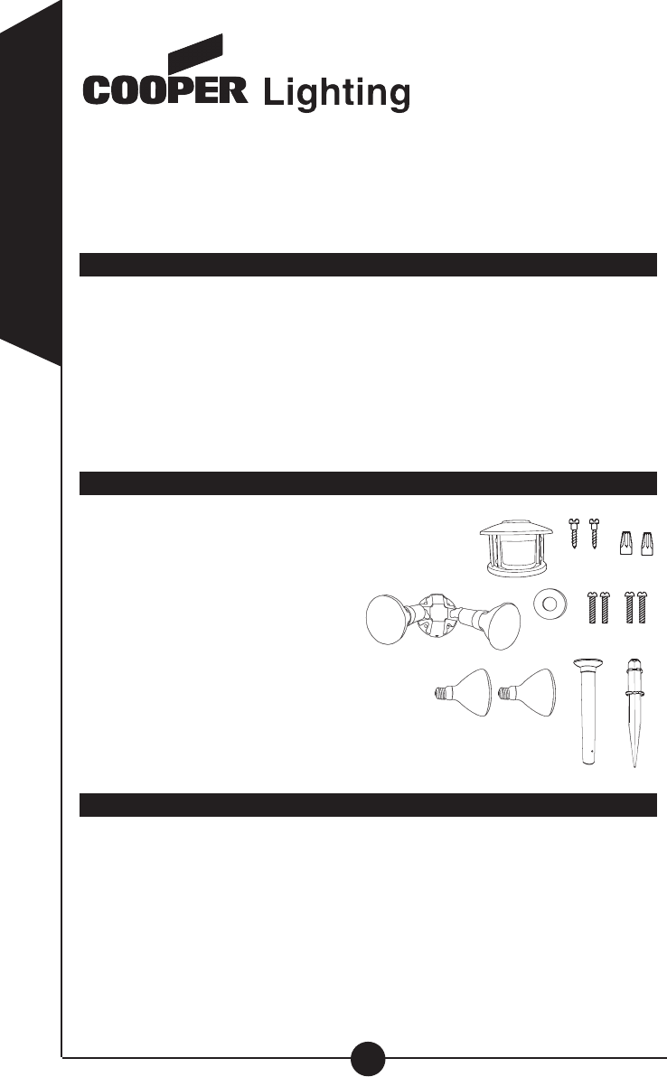
What’s included
• Battery operated landscape motion sensor (A)
• (2) 6-32 Light fixture mounting screws (B)
• Light fixture (receiver) (C)
• Coverplate gasket (D)
• (2) 8-32 Light fixture mounting
screws (E)
• Wire nuts (F)
• (2) Floodlight bulbs (G)
• Stainless steel post mounting screws (H)
• Motion sensor post (I)
• Motion sensor spike (J)
What to know
PLEASE READ THESE IMPORTANT SAFETY INSTRUCTIONS.
• For outdoor use only.
• UL/cUL LISTED for wet locations.
• Landscape motion sensor must be powered by (4) AA Alkaline Batteries
(6VDC Rating)
• Floodlight must be connected to a 120Volt, 60Hz power source. Any other
connection voids warranty.
2
ENGLISH
Call for customer service and/or missing
or damaged parts (800-334-6871)
AB
CDEH
IJ
F
G

3
ENGLISH
• WARNING: Risk of fire/electric shock. This motion activated floodlight
system, should be installed by persons with experience in household
wiring or by a qualified electrician. The electrical system, and the method
of electrically connecting the fixture to it, must be in accordance with the
National Electrical Code and local building codes.
• WARNING: Risk of fire. If uncertain, consult an electrician.
• Disassembly of your fixture will void the warranty.
• Exercise care in handling the batteries in order not to short the battery
with conductive materials such as rings, bracelets and keys. The battery
or conductor may overheat and cause burns.
• Observe proper polarity orientation between the batteries and battery
compartment.
• Do not mix old and new batteries or batteries of different sizes in
this product.
• This device complies with Part 15 of the FCC Rules. Operation is subject
to the following two conditions: (1) This device may not cause harmful
interference, and (2) this device must accept any interference received,
including interference that may cause undesired operation. Under Part 15
of the FCC Rules, any changes or modifications to the motion detector
described in this instruction sheet that are not expressly approved by
Cooper Lighting could void the user’s authority to operate the equipment.
NOTE: This equipment has been tested and found to comply with the lim-
its for a Class B digital device, pursuant to part 15 of the FCC Rules.
These limits are designed to provide reasonable protection against harm-
ful interference in a residential installation. This equipment generates,
uses and can radiate radio frequency energy and if not installed and used
in accordance with the instructions, may cause harmful interference to
radio communications. However, there is no guarantee that interference
will not occur in a particular installation. If this equipment does cause
harmful interference to radio or television reception, which can be deter-
mined by turning the equipment off and on, the user is encouraged to try
to correct the interference by one or more of the following measures:
• Reorient or relocate the receiving antenna.
• Increase the separation between the equipment and receiver.
• Connect the equipment into an outlet on a circuit different from that to
which the receiver is connected.
• Consult the dealer or an experienced radio/TV technician for help.
•NOTE: FCC Regulations state that any unauthorized changes or modifi-
cations to this equipment not expressly approved by the manufacturer
could void the user's authorization to operate this equipment.
• Floodlight is suitable for wall-mount only.
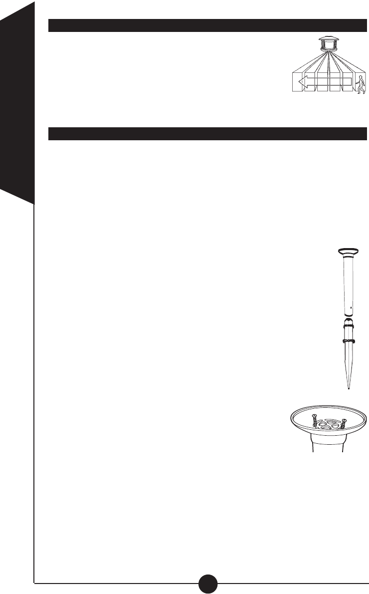
For best results
• Locate motion sensor so motion moves across
detection zone (K).
• Locate sensor away from heat producing sources to
prevent false triggering. Also, be very careful not to
include objects such as windows, white walls and water
in the detection zone whenever possible.
• Locate sensor away from moving objects such as street traffic.
Installing your landscape motion sensor transmitter
Step 1: Choose a desired location in your yard for landscape motion sen-
sor that has a clear view of driveway, walkway or area where motion is to
be detected. The landscape motion sensor will transmit up to 100 feet in
most cases, therefore, it must be located within this range from floodlight
receiver (a closer distance will achieve more consistent performance).
Step 2: Contact your local Utility Company to be sure that there are no
buried utilities in the selected installation site before installing spike. Adjust
installation site until a safe location has been found. Do not continue until
this step has been completed!
Step 3: Safety glasses must be worn during this installation step.
Place pointed end of mounting spike (J) on ground in approved
installation location. Using hammer/mallet drive mounting spike
into ground making sure that spike is as close to vertical as pos-
sible. Do not drive spike in ground any further than first horizontal
flange from the pointed end.
Step 4: Slide bottom end of post over top end of spike making
sure that vertical ribs on spike slide in between vertical ribs inside
of post. Holes on post align with holes in spike (L). Post will stop
with bottom of post at the top of largest horizontal rib on spike.
Step 5: Install both post mounting screws through holes in side
of post to secure post to spike.
Step 6: Loosen two screws on top flange of post and
point arrow towards center of desired detection area.
This could require removing the screws and installing
them again if slotted holes will not allow arrow to point
to center of desired detection area (M).
Step 7: Remove battery cover from driveway sensor head (A) by removing
screw from recessed hole in center of back cover. Install (4) "AA" alkaline
batteries in battery compartment making sure that batteries are installed in
the correct orientation as shown on printed diagram in battery area. Allow
60 seconds after batteries are installed before testing (see How to operate
your fixture for correct settings before replacing cover). Replace back cover
by aligning groove around perimeter of back cover with rib around perime-
ter of battery compartment while making sure that recessed screw hole
aligns with screw boss. Replace screw in recessed hole in battery cover
and tighten to secure cover to sensor housing.
4
ENGLISH
K
L
M
Step 8: Install motion sensor head (A) on driveway sensor post (I) by align-
ing slots in flange on bottom of sensor head with protrusions on side of post
top. NOTE: Make sure motion sensor front is in the same orientation as
arrow on post flange. Rotate sensor head clockwise until locked in place.
Lens of sensor head should be pointing toward desired detection area.
Mounting your light fixture (receiver)
Step 1: WARNING: Risk of electric shock.
Disconnect power at fuse or circuit breaker
before installing or servicing.
Step 2: This mounting plate has been
designed to work with a variety of different
junction boxes. Line up the knockout holes
in the mounting plate with the screw loca-
tions in your junction box. Drill out the
matching holes in the mounting plate, using an electric drill and a 1/8" drill
bit or knock out the hole with a punch and hammer.
Step 3: Take the gasket included with this mounting plate and position it
behind the mounting plate. Line up the screws in the mounting plate with
the appropriate hole pattern in the gasket and remove gasket material in
those holes. When wall mounting, locate arrow on back of mounting plate
and mount with arrow pointing up.
Step 4: Connect lampholder wires to supply wires from house (white to
white and black to black) using wire nuts included. No ground wire
required. Attach any ground wire from your house to the junction box.
Step 5: Attach the mounting plate to your junction box using screws includ-
ed, making sure that the gasket is properly aligned and that all screws are
tightly secured. To prevent moisture from entering the junction box, apply a
bead of silicone sealant around the edge of the mounting plate where it
attaches to the junction box.
Step 6: Turn power on at the main fuse/breaker box.
Aiming the light
Loosen the knob on the side of the lamp holder. Tilt lamp holder up or
down to desired position then retighten knob. Tilt lamp holders at least 15°
downward. NOTE: Deviation from the assembly instructions may result in a
risk or electric shock.
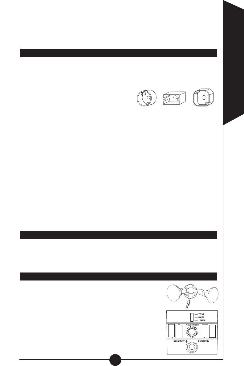
How to operate your fixture
Step 1: Make sure motion sensor and remote light are
set to the same house code (fixtures will come from
factory already set to the same code). You may reset
the house code by turning the dial inside the battery
compartment of the driveway sensor head and the bot-
tom of the floodlight to the same number (N). There are
16 different selections
Step 2: Move slide switch inside battery compartment
of driveway sensor head to "TEST". Set sensitivity
knob to medium (halfway).
5
ENGLISH
N
Round Rectangular (horizontal) Octagonal
Your fixture mounts
to the following standard
junction boxes:
Step 3: Turn on power to floodlight receiver.
Step 4: Aim driveway sensor head toward desired detection area.
Step 5: Walk across the detection zone at the farthest distance you wish
your detector to detect motion. Adjust sensitivity until you get desired results.
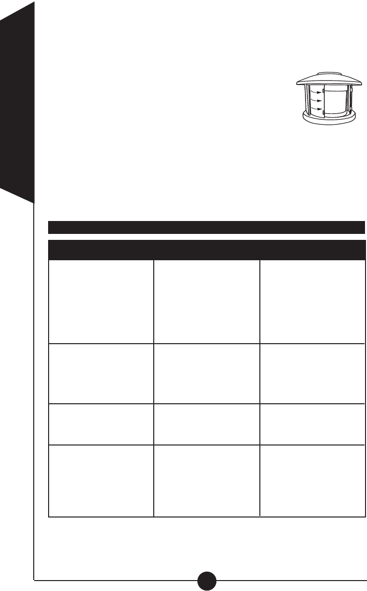
Step 6: Your sensor is equipped with two lens shutters,
which will allow you to customize your detection area
down to 90 degrees. If the sensor is seeing at too wide
of an angle, or if you wish to block certain areas from
being detected, you can do so by simply locating the
shutters on either side of the lens. Carefully pull the
shutter(s) out using the two tabs on the front of the shutter (O). NOTE: Be
sure to use two fingers and pull the upper and lower tab simultaneously to
insure proper and even sliding. Each shutter will extend approximately 1-
1/2" to help prevent either side of the sensor from detecting motion.
Step 7: Move slide switch inside battery compartment to 4 MIN or 12 MIN
(AUTO mode). At dusk your lights will operate in the AUTO setting.
Step 8: Replace cover after all adjustments are made.
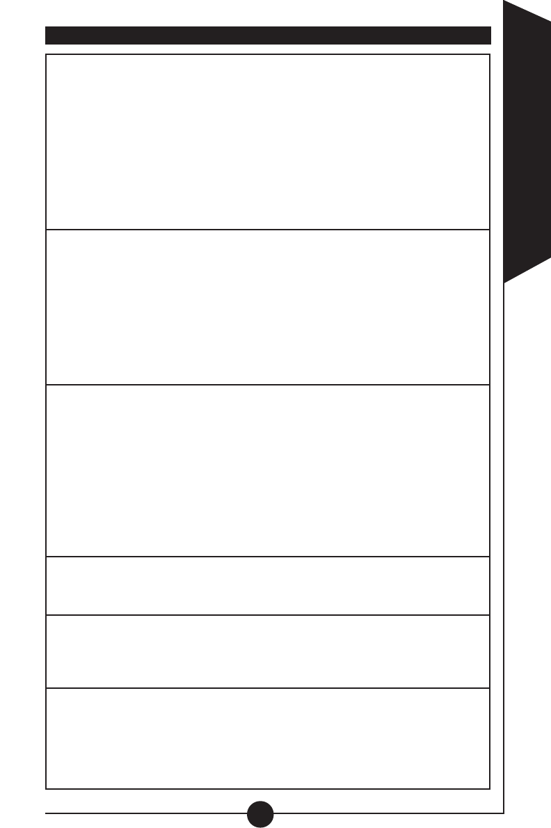
How to select your desired feature
6
ENGLISH
Auto Setting
(motion activated)
Floodlight will
automatically turn ON when
motion is detected by the
motion sensor, and will
remain ON for four or
twelve minutes after motion
has stopped.
Set slide switch to:
4 MIN
or
12 MIN
Make sure power
is on to the
floodlight.
Manual Override
Allows floodlight to be
manually turned ON and
used as a standard flood-
light. Light will stay on
for four hours.
Any position Turn power to the floodlight
off for 2 seconds and back
to the ON position using
indoor wall switch.
Test Setting
This mode is used for
set up of fixture during initial
installation. It allows flood-
light to turn on both day
and night and stay ON for
eight seconds.
TEST Make sure power is on
to the floodlight.
Mode of
Operation: Motion Sensor
(Transmitter) Floodlight
(Receiver)
Reset Manual Override
To resume motion
activated mode.
To reset floodlight turn
power off for 10 seconds
and resume power for
motion activated mode.
O
7
ENGLISH
What to do if . . .QUENTIAL DAMAGES RESULTING FROM
Is there power to the floodlight?
•Check to see that the circuit breaker has not
been tripped.
• Be sure the wall switch is in the “ON” position.
•Be sure that the bulb is not burned out or broken.
Is the surrounding external ambient light too bright? (If so,
the unit may think it’s daytime.)
•Relocate or reposition the unit away from the light.
Do the batteries need replacing in landscape motion sensor?
TURN OFF POWER BEFORE CONTINUING.
Is the wiring to the fixture loose?
•Check wiring and reconnect, if necessary, using Quick-
ConnectTM or wire nuts provided.
OUTDOOR FLOODLIGHT
DOES NOT COME
ON WITH MOTION
AT NIGHT
Is there motion in the detection zone?
• Make sure the sensor is not picking up moving objects
such as trees, traffic, etc.
TEST FOR YOURSELF
• Cover the sensor lens with cardboard to prevent sensor
from detecting motion. If the floodlight stays off, some-
thing in the detection zone is triggering the sensor.
• If this is the case, reduce the sensitivity.
* If the light stays on with sensor lens covered, contact
customer service.
Is the unit in the AUTO mode?
OUTDOOR FLOODLIGHT
COMES ON FOR NO
APPARENT REASON
AT NIGHT
FLOODLIGHT CONTINU-
OUSLY BLINKS ON AND
OFF AT NIGHT
The light given off from a lantern or a light source next to it is
affecting the motion sensor.
• Reposition away from light.
CANNOT ACTIVATE
DUSK TO DAWN MODE
AT NIGHT (OVERRIDE)
Is the surrounding external ambient light too bright? (If so, the
unit may think it’s daytime.)
• Relocate or reposition the unit away from the light.
Are you allowing adequate time to enter the dusk to dawn
mode?
•Turn the inside light switch to the “OFF” position for 5
seconds, and then back to the “ON” position.
FLOODLIGHT STAYS ON
AT NIGHT AND DOES
NOT TURN OFF
Is there motion in the detection zone?
• Make sure the sensor is not picking up moving objects
such as trees, traffic, etc.
• If this is the case, reduce the sensitivity.
• Rotate lens to reposition motion sensor.
If there is no motion, then the unit may be in the override
mode.
• Turn the inside light switch to the “OFF” position for 90
seconds, and then back to the “ON” position. This will
send the unit back into the AUTO mode.
* If the floodlight continues to stay on, contact
customer service.
Is the unit in the AUTO mode?
FLOODLIGHT IS ON
DURING THE DAY
Is the switch on the floodlight base plate in the test mode?
• Move the switch to the AUTO 4 or AUTO 12 position.
Is the motion detector shadowed?
•Reposition motion sensor.
•Reposition floodlight.

Two Year Limited Warranty
Cooper Lighting (“the Company”) warrants this product (“the product”) against
defects in material or workmanship for a period of two years from date of original
purchase, and agrees to repair or, at the Company’s option, replace a defective
product without charge for either replacement parts or labor during such time. This
does not include labor to remove or install fixtures.
This warranty is extended only to the original purchaser of the product. A pur-
chasers receipt or other proof of date of original purchase acceptable to the
Company is required before warranty performance shall be rendered.
This warranty only covers product failure due to defects in materials or workmanship
which occurs in normal use. It does not cover the bulb or failure of the product
caused by accident, misuse, abuse, lack of reasonable care, alteration, or faulty
installation, subjecting the product to any but the specified electrical service or any
other failure not resulting from defects in materials or workmanship. Damage to the
product caused by separately purchased, non-Company brand replacement bulbs
and corrosion or discoloration of brass components are not covered by this warranty.
There are no express warranties except as described above.
THE COMPANY SHALL NOT BE LIABLE FOR INCIDENTAL, SPECIAL OR CONSE-
QUENTIAL DAMAGES RESULTING FROM THE USE OF THE PRODUCT OR ARIS-
ING OUT OF ANY BREACH OF THIS WARRANTY. ALL IMPLIED WARRANTIES, IF
ANY, INCLUDING IMPLIED WARRANTIES OF MERCHANTABILITY AND FITNESS
FOR A PARTICULAR PURPOSE, ARE LIMITED IN DURATION TO THE DURATION
OF THIS EXPRESS WARRANTY. Some states do not allow the exclusion or limitation
of incidental or consequential damages, or limitations on how long an implied warranty
lasts, so the above exclusions or limitations may not apply to you.
No other warranty, written or verbal, is authorized by the Company.This warranty
gives you specific legal rights, and you may also have other rights which vary from
state to state.
To obtain warranty service, please write to Cooper Lighting, 1121 Highway 74
South, Peachtree City, GA 30269. Enclose product model number and problems
you are experiencing, along with your address and telephone number. You will then
be contacted with a solution, or a Return Goods Authorization number and full
instructions for returning the product. All returned products must be accompanied by
a Return Goods Authorization Number issued by the Company and must be
returned freight prepaid. Any product received without a Return Goods
Authorization Number from the Company will be refused.
Cooper Lighting is not responsible for merchandise damaged in transit. Repaired or
replaced products shall be subject to the terms of this warranty and are inspected
when packed. Evident or concealed damage that is made in transit should be
reported at once to the carrier making the delivery and a claim filed with them.
8
ENGLISH
1121 Highway 74 South, Peachtree City, GA 30269 USA
1-800-334-6871
www.cooperlighting.com
Reproductions of this document without prior written approval of Cooper Lighting are strictly prohibited.
Printed in China