Corning Optical Communication Wireless 1C85P19L70A17 OPTICAL NETWORK EVOLUTION DAS User Manual GENII
Corning Optical Communication Wireless OPTICAL NETWORK EVOLUTION DAS GENII
Contents
- 1. User Manual
- 2. Users Manual
User Manual

APRIL 2013
Corning
ONE™ Wireless Platform
User Manual

Preface Material
P/N 709C011801
Page 2
Preface Material
About This Manual
This user guide provides all the information necessary to understand the architecture and perform the installation of
Corning® ONE™ Wireless Platform.
Hardware
Corning warrants to the original purchaser (“Customer”) that for the duration of the warranty period, one (1) year,
commencing on the date of shipment of the Hardware, unless otherwise agreed in writing by Corning (the “Hardware
Warranty Period”), the Hardware furnished by Corning shall be free in all material respects from defects in material
and workmanship, and shall conform to the applicable portions of the Specifications, as defined below (the
“Hardware Warranty”).
If notified by Customer of any such defects in material or workmanship or nonconformity with applicable portions of
the Specifications within the Hardware Warranty Period, Corning shall promptly, at its own election and expense,
repair or replace any such Hardware proven to be defective under the terms of this Hardware Warranty.
Such repair or replacement shall be Customer’s sole remedy and Corning sole obligation in the event this Hardware
Warranty is invoked. If any components comprising a part of the Hardware are replaced or repaired during the
Hardware Warranty Period, the Hardware Warranty Period for such repaired or replaced components shall extend to
the longer of (i) the balance of the Hardware Warranty Period or (ii) three (3) months from the date of repair or
replacement. For purposes of this Warranty, “Specifications” shall mean the specifications and performance
standards of the Products as set forth in documents published by Corning and delivered to Customer which contain
technical specifications or performance standards for the Products.
If Customer invokes this Hardware Warranty, it shall notify Corning promptly of the claimed defect.
Customer will allow Corning to inspect the Hardware at Customer’s location, or to return the Hardware to Corning
closest repair facility. For Hardware returned to Corning repair facility, Customer shall be responsible for payment of
all transportation and freight costs (including insurance) to Cornings’ repair facility, and Corning shall be responsible
for all transportation and freight costs (including insurance) incurred in connection with the shipment of such
Hardware to other repair facilities of Corning and/or its return to Customer.
Notwithstanding the foregoing, in no event will Corning be liable for damage to Products resulting from improper
handling during or after shipment, misuse, neglect, improper installation, operation or repair (other than by
authorized Corning personnel), alteration, accident, or for any other cause not attributable to defects in materials or
workmanship on the part of Corning. Corning shall not reimburse or make any allowance to Customer for any labor
charges incurred by Customer for replacement or repair of any goods unless such charges are authorized in advance
in writing by Corning.

Preface Material
P/N 709C011801
Page 3
Software Warranty
Corning warrants to the original purchaser (“Customer”) that for the duration of the warranty period, one (1) year,
commencing on the date of shipment of the Software, unless otherwise agreed in writing by Corning (the “Software
Warranty Period”), the Software shall conform with, and perform the functions set forth in the Specifications, and
shall be free from defects in material or workmanship (the “Software Warranty”). In the event the Software is proven
to be defective under the terms of this Software Warranty, Corning shall correct such defects or failure and ensure
that the Software conforms with, and performs the functions set forth in, the Specifications. Customer will allow
Corning to inspect the Software at Customer’s location or to return it to Cornings’ closest repair facility.
Notwithstanding the foregoing, Corning shall have no obligation under the Software Warranty if the
Software is modified or used with hardware or software not supplied or approved by Corning or if the Software is
subject to abuse, improper installation or application, accident, electrical or environmental over-stress, negligence in
use, storage, transportation or handling.
Third-party software distributed with the Software may carry certain warranties which, to the maximum extent
allowed by law, Corning hereby assigns, transfers and otherwise conveys to Customer, provided, however, that
Corning itself provides no warranty of any kind, express, implied, statutory or otherwise, for any third-party software
provided hereunder.
Corning does not warrant any hardware, software or services not provided by Corning.
THIS WARRANTY IS THE ONLY WARRANTY MADE BY CORNING AND IS IN LIEU OF ALL OTHER
WARRANTIES, EXPRESS OR IMPLIED INCLUDING, BUT NOT LIMITED TO, THE IMPLIED
WARRANTIES OF MERCHANTABILITY AND FITNESS FOR A PARTICULAR PURPOSE. CORNING
SHALL NOT BE LIABLE FOR ANY OTHER DAMAGE INCLUDING, BUT
NOT LIMITED TO, INDIRECT, SPECIAL OR CONSEQUENTIAL DAMAGES ARISING OUT OF OR
IN CONNECTION WITH FURNISHING OF GOODS, PARTS AND SERVICE HEREUNDER, OR THE
PERFORMANCE, USE OF, OR INABILITY TO USE THE GOODS, PARTS AND SERVICE.
CORNING SALES AGENTS OR REPRESENTATIVES ARE NOT AUTHORIZED TO MAKE
COMMITMENTS ON WARRANTY RETURNS.
Returns
In the event that it is necessary to return any product against above warranty, the following procedure shall be
followed:
1. Return authorization is to be received from Corning prior to returning any unit. Advise Corning of the model,
Serial number, and discrepancy. The unit may then be forwarded to Corning, transportation prepaid. Devices
returned collect or without authorization may not be accepted.
2. Prior to repair, Corning will advise the customer of our test results and any charges for repairing customer-caused
problems or out-of-warranty conditions etc.
3. Repaired products are warranted for the balance of the original warranty period, or at least 90 days from date of
shipment.

Preface Material
P/N 709C011801
Page 4
Limitations of Liabilities
Corning’s liability on any claim, of any kind, including negligence for any loss or damage arising from, connected
with, or resulting from the purchase order, contract, quotation, or from the performance or breach thereof, or from the
design, manufacture, sale, delivery, installation, inspection, operation or use of any equipment covered by or
furnished under this contact, shall in no case exceed the purchase price of the device which gives rise to the claim.
Except as expressly provided herein, Corning makes no warranty, expressed or implied, with respect to any goods,
parts and services provided in connection with this agreement including, but not limited to, the implied warranties of
merchantability and fitness for a particular purpose. Corning shall not be liable for any other damage including, but
not limited to, indirect, special or consequential damages arising out of or in connection with furnishing of goods,
parts and service hereunder, or the performance, use of, or inability to use the goods, parts and service.
Reporting Defects
The units were inspected before shipment and found to be free of mechanical and electrical defects. Examine the
units for any damage that may have been caused in transit. If damage is discovered, file a claim with the freight
carrier immediately. Notify Corning as soon as possible in writing.
N ote: Keep all packing material until you have completed the inspection

Warnings and Admonishments
P/N 709C011801
Page 5
Warnings and Admonishments
There may be situations, particularly for workplace environments near high-powered RF sources, where
recommended limits for safe exposure of human beings to RF energy could be exceeded. In such cases, restrictive
measures or actions may be necessary to ensure the safe use of RF energy.
The equipment has been designed and constructed to prevent, as far as reasonably, practicable danger. Any work
activity on or near equipment involving installation, operation or maintenance must be, as far as reasonably, free
from danger.
Where there is a risk of damage to electrical systems involving adverse weather, extreme temperatures, wet,
corrosive or dirty conditions, flammable or explosive atmospheres, the system must be suitably installed to prevent
danger.
Equipment provided for the purpose of protecting individuals from electrical risk must be suitable for the purpose
and properly maintained and used. This covers a range of activities including lifting, lowering, pushing, pulling,
carrying, moving, holding or restraining an object, animal or person from the equipment. It also covers activities that
require the use of force or effort, such as pulling a lever, or operating power tools.
Where some of the abovementioned activities are required, the equipment must be handled with care to avoid being
damaged.
Observe standard precautions for handling ESD-sensitive devices. Assume that all solid-state electronic devices are
ESD-sensitive. Ensure the use of a grounded wrist strap or equivalent while working with ESD-sensitive devices.
Transport, store, and handle ESD-sensitive devices in static-safe environments.
RF Safety
To comply with FCC RF exposure compliance requirement, adhere to the following warnings:
Warning! Antennas used for this product must be fixed mounted on indoor permanent structures, providing a separation
distance of at least 50 cm from all persons during normal operation.
Warning! Each individual antenna used for this transmitter must be installed to provide a minimum separation distance of 50 cm
or more from all persons and must not be co-located with any other antenna for meeting RF exposure requirements.
Warning! Antenna gain should not exceed 12.5 dBi.
Warning! The design of the antenna installation needs to be implemented in such a way so as to ensure RF radiation safety
levels and non-environmental pollution during operation.

Company Certification
P/N 709C011801
Page 6
ATTENTION!
Compliance with RF safety requirements:
• Corning products have no inherent significant RF radiation
• The RF level on the downlink is very low at the downlink ports. Therefore, there is no dangerous RF radiation
when the antenna is not connected.
CAUTION!
Use of controls, adjustments or performance of procedures other than those specified herein may result in hazardous
radiation exposure.
Laser Safety
• Fiber optic ports of the ONE™ system emit invisible laser radiation at the 1310/1550 nm wavelength window.
• External optical power is less than 10 mW, Internal optical power is less than 500 mW.
• To avoid eye injury never look directly into the optical ports, patchcords or optical cables. Do not stare into beam
or view directly with optical instruments. Always assume that optical outputs are on.
• Only technicians familiar with fiber optic safety practices and procedures should perform optical fiber
connections and disconnections of ONE™ devices and the associated cables.
• ONE™ has been tested and certified as a Class 1 Laser product to IEC/EN 60825-1 (2007). It also meets the
requirements for a Hazard Level 1 laser product to IEC/EN 60825-2: 2004 to the same degree.
• ONE™ complies with 21 CFR 1040.10 and 1040.11 except for deviations pursuant to Laser Notice NO. 50
(2007).
• ONE™ employs a Class 3B laser and therefore the following label is affixed inside the unit adjacent to the laser:
Care of Fiber Optic Connectors
• Do not remove the protective covers on the fiber optic connectors until a connection is ready to be made. Do not
leave connectors uncovered when not connected.
• The tip of the fiber optic connector should not come into contact with any object or dust.
• Refer to the cleaning procedure for information on the cleaning of the fiber tip.
Company Certification
ISO 9001: 2000 and ISO 13485: 2003

Table of Contents
P/N 709C011801
Page 7
T
Ta
ab
bl
le
e
o
of
f
C
Co
on
nt
te
en
nt
ts
s
Preface Material ................................................................................................................................................... 2
About This Manual ................................................................................................................................................. 2
Hardware ............................................................................................................................................................... 2
Software Warranty ................................................................................................................................................. 3
Returns .................................................................................................................................................................. 3
Limitations of Liabilities .......................................................................................................................................... 4
Reporting Defects .................................................................................................................................................. 4
Warnings and Admonishments........................................................................................................................... 5
RF Safety ............................................................................................................................................................... 5
Laser Safety ........................................................................................................................................................... 6
Care of Fiber Optic Connectors .............................................................................................................................. 6
C ompany C ertification ......................................................................................................................................... 6
Table of Contents ................................................................................................................................................. 7
1 Introduction ................................................................................................................................................. 13
1.1 About ONE™ ................................................................................................................................................ 13
1.2 Key Features and Capabilities ....................................................................................................................... 14
1.3 General System Specifications and Requirements ........................................................................................ 14
1.3.1 Supported Browsers ............................................................................................................................. 14
1.3.2 Environmental and Regulatory Specifications ...................................................................................... 14
1.3.2.1 Temperature and Humidity ..................................................................................................... 14
1.3.2.2 Safety and Regulatory Approvals ........................................................................................... 15
1.3.3 Power Consumption of Units ................................................................................................................ 15
1.3.3.1 General Power Safety Instructions ......................................................................................... 15
1.3.4 Dimensions and Weight of Units .......................................................................................................... 16
1.3.5 Optical Specifications ........................................................................................................................... 16
1.3.6 Default Network and User Settings ...................................................................................................... 17
1.3.6.1 Default Network Parameters ................................................................................................... 17
1.3.6.2 System Administrator or "Super User" .................................................................................... 17
1.3.6.3 Default Group Admin .............................................................................................................. 17

Table of Contents
P/N 709C011801
Page 8
1.4 Installation Guidelines ................................................................................................................................... 18
1.4.1 Rack Mount Procedure ........................................................................................................................ 18
1.4.1.1 General Instructions ............................................................................................................... 18
1.4.1.2 Rack Installation Safety Instructions ....................................................................................... 19
1.4.2 Power Consumption, Connections and Power Supplies ....................................................................... 19
1.4.2.1 Power Safety Instructions ....................................................................................................... 19
1.4.2.2 Types of Power Supplies ........................................................................................................ 19
1.4.2.3 Circuit Breakers ...................................................................................................................... 19
1.5 System Architecture and Topologies ............................................................................................................. 20
1.5.1 RF Path ................................................................................................................................................ 20
1.5.2 Digital Path .......................................................................................................................................... 21
1.6 ONE™ WEB Management Application .......................................................................................................... 21
1.6.1 Overall Device Display - Configuration Tab .......................................................................................... 23
1.6.2 Session Access .................................................................................................................................... 23
1.7 User Controlled Sectorization ........................................................................................................................ 24
1.7.1 MIMO Configurations ........................................................................................................................... 25
1.7.2 Single Sector Example ......................................................................................................................... 25
1.7.3 Dual Sector Example ........................................................................................................................... 26
1.7.4 Tri-sector Example ............................................................................................................................... 26
1.7.5 Tri-sector Example with Two HEUs ...................................................................................................... 27
2 Unit Des criptions - R F P ath ........................................................................................................................ 29
2.1 RF Path - Headend Components .................................................................................................................. 29
2.1.1 HEU (Headend Unit) ............................................................................................................................ 29
2.1.1.1 HCM (Headend Control Module) ............................................................................................ 30
2.1.1.2 RIM/RIM-M (RF Interface Module) .......................................................................................... 31
2.1.1.3 RIX (RF Expander Module) .................................................................................................... 33
2.1.1.4 PSM (Power Supply Module) .................................................................................................. 33
2.1.2 OIU (Optical Interface Unit) .................................................................................................................. 34
2.1.2.1 ACM (Auxiliary Control Module).............................................................................................. 35
2.1.2.2 OIM (Optical Interface Module) ............................................................................................... 36

Table of Contents
P/N 709C011801
Page 9
2.1.2.3 OIX (Optical Expander Module) .............................................................................................. 37
2.2 RF Path Remote End Site Components ........................................................................................................ 38
2.2.1 ICU (Intermediate Centralized Unit) ..................................................................................................... 38
2.2.2 RAU (Remote Antenna Unit) ................................................................................................................ 39
2.2.2.1 RxU (Remote Expansion Unit) ................................................................................................ 40
3 Unit Des criptions - Digital P ath .................................................................................................................. 41
3.1 Digital Path Components ............................................................................................................................... 41
3.2 CEU (Centralized Ethernet Unit) ................................................................................................................... 41
3.2.1 CEM (Centralized Ethernet Module) ..................................................................................................... 42
3.3 GEM (Gigabit Ethernet Module) .................................................................................................................... 43
3.4 GEU-S (GEM Standalone) ............................................................................................................................ 44
4 Ins tallation – R F P ath E lements ................................................................................................................. 45
4.1 RF Headend Installation ................................................................................................................................ 45
4.1.1 HEU Installation ................................................................................................................................... 45
4.1.2 Example of HEU Master-Slave Installation ........................................................................................... 47
4.1.3 OIU Installation .................................................................................................................................... 47
4.2 RF Remote-End Installation .......................................................................................................................... 48
4.2.1 ICU Installation ..................................................................................................................................... 48
4.2.1.1 General Information ................................................................................................................ 48
4.2.2 RAU Installation ................................................................................................................................... 49
4.2.2.1 General Information ................................................................................................................ 49
4.2.3 RxU Installation .................................................................................................................................... 50
4.2.3.1 General Information ................................................................................................................ 50
5 Ins tallation – Digital Coverage E lements ................................................................................................... 51
5.1 CEU Installation ............................................................................................................................................ 51
5.2 GEM .............................................................................................................................................................. 52
5.2.1 GEM Installations with RAU Module ..................................................................................................... 52
5.2.2 GEU-S Installations .............................................................................................................................. 53
6 Commis sioning the S ys tem ....................................................................................................................... 55
6.1 Opening a Local Session .............................................................................................................................. 55
6.2 Configuring HCM Network Settings for Local and Remote Management ....................................................... 57
6.2.1 Default Network Parameters ................................................................................................................ 59

Table of Contents
P/N 709C011801
Page 10
6.2.2 Ping Tool - Verifying IP Host Access .................................................................................................... 60
6.3 Required Pre-Setup Procedures ................................................................................................................... 61
6.4 Running the Setup Procedure ....................................................................................................................... 63
6.5 System Adjustment Procedure ...................................................................................................................... 73
6.6 About the Setup Tool .................................................................................................................................... 74
6.6.1 Overview of Setup Procedure .............................................................................................................. 75
6.6.2 Default Values Assigned in Setup Tool ................................................................................................ 76
6.6.3 Navigating the Setup Tool .................................................................................................................... 76
6.6.3.1 Module Owner ........................................................................................................................ 78
6.6.3.2 Zone Information .................................................................................................................... 79
6.6.3.3 MIMO-SETUP ........................................................................................................................ 81
6.6.3.4 RF Path .................................................................................................................................. 82
6.6.3.5 Max Input ............................................................................................................................... 84
6.6.3.6 ALC ........................................................................................................................................ 84
6.6.3.7 UL Gain .................................................................................................................................. 85
6.6.3.8 AGC ....................................................................................................................................... 87
6.6.3.9 Adjustment ............................................................................................................................. 89
7 Device Configuration .................................................................................................................................. 91
7.1 System Management (HCM) ......................................................................................................................... 93
7.2 HEU Configuration ........................................................................................................................................ 94
7.2.1 HEU ACM ............................................................................................................................................ 94
7.2.2 RIM ...................................................................................................................................................... 95
7.3 OIU Configuration ......................................................................................................................................... 97
7.3.1 OIU ACM ............................................................................................................................................. 97
7.3.2 OIM ...................................................................................................................................................... 98
7.4 RAU Configuration ........................................................................................................................................ 99
7.5 RxU Configuration ....................................................................................................................................... 101
7.6 Removing a Hosted Device from Baseline .................................................................................................. 103
8 Administration ........................................................................................................................................... 105
8.1 Management Menu Tab .............................................................................................................................. 105
8.2 Multi User Account Management ................................................................................................................ 106
8.2.1 Defining User Groups ......................................................................................................................... 107
8.2.2 Defining User Accounts ...................................................................................................................... 109

Table of Contents
P/N 709C011801
Page 11
8.2.3 Group Users Access Levels ............................................................................................................... 111
8.2.4 Modifying Passwords ......................................................................................................................... 112
8.2.4.1 System Admin Password Change ........................................................................................ 112
8.2.4.2 Group Admin Password Change .......................................................................................... 113
8.2.4.3 User Own Password Change ............................................................................................... 115
8.2.5 Session Timeout Settings................................................................................................................... 116
8.3 Backup & Restore Configurations ............................................................................................................... 117
8.4 Generating Device Reports ......................................................................................................................... 118
8.5 Activity Log .................................................................................................................................................. 120
8.6 Firmware Upgrade ...................................................................................................................................... 121
9 Monitoring and Troubleshooting ............................................................................................................. 123
9.1 Overview ..................................................................................................................................................... 123
9.2 Network Topology Tree - Fault Sourcing ..................................................................................................... 124
9.3 Fault Sourcing through the Device View and Alarms Tab ............................................................................ 126
9.3.1 HCM (System Management) Device View and Alarms ....................................................................... 126
9.3.2 ACM Device Alarms and View ........................................................................................................... 127
9.3.3 RIM Module Device View and Alarms ................................................................................................ 129
9.3.4 OIM Device View and Alarms ............................................................................................................. 130
9.3.5 RAU Device View and Alarms ............................................................................................................ 131
9.3.6 RxU View ........................................................................................................................................... 132
9.4 Masking Irrelevant Alarms ........................................................................................................................... 133
9.5 Events Display ............................................................................................................................................ 134
9.5.1 Filtering Displayed Events .................................................................................................................. 135

Table of Contents
P/N 709C011801
Page 12
10 S NMP Management ................................................................................................................................... 137
10.1 SNMP Destination Address Configuration .......................................................................................... 137
10.2 Modifying the Read/Write Community Parameters ............................................................................. 138
10.3 SNMP Management using any Third Party SNMP Manager .............................................................. 138
10.4 Loading the MIB Files ........................................................................................................................ 139
10.5 Viewing the Traps .............................................................................................................................. 139
10.6 Binding Table ..................................................................................................................................... 140
10.7 Monitoring the Managed System ........................................................................................................ 141
10.8 List of Traps ....................................................................................................................................... 142
Appendix A: S pecifications ............................................................................................................................. 145
Supported Services ............................................................................................................................................ 145
RF Parameters per Service ................................................................................................................................ 145
Environmental, Standards and Optical ............................................................................................................... 146
Unit Specifications ............................................................................................................................................. 147
RF Coverage Component Specifications ............................................................................................ 147
Digital Coverage Component Specifications ...................................................................................... 150
Ordering Information .......................................................................................................................................... 153
HEU Chassis and Modules ................................................................................................................ 153
OIU Chassis and Modules .................................................................................................................. 153
Remote Units ..................................................................................................................................... 154
Digital Path Units ............................................................................................................................... 154
Accessories........................................................................................................................................ 154
Introduction
P/N 709C011801
Page 13
1 Introduction
1.1 About ONE™
The Optical Network Evolution Platform (ONE™) by Corning provides a flexible in-building RF and network digital coverage
solution based on a fiber optic transport backbone.
The fiber-optics infrastructure is easily deployable via a wide range of pre-terminated composite cables and advanced
end-to-end equipment. Easy to design, Plug and Play™ connectors, significantly reduce installation cost and deployment time.
The ONE™ solution is an ideal fit for large, high-rise or campus-style deployments. It generates significant CAPEX savings and
OPEX savings through the use of user configurable sectorization and an infrastructure that is simple to deploy and efficient in
usage.
Dynamic sectorization management allows precise service distribution control to meet changing density needs, and provides
further savings by enabling sharing of equipment at various levels for service providers.
Radio source agnostic, remote units can be used as network extenders. Ethernet capability with dedicated fiber link for Wi-Fi
offload brings a higher level of granularity and support for devices and applications with very high speed requirements.
Figure 1-1. Illustration of Precise Service Distribution over Selected Remote Areas
Introduction
P/N 709C011801
Page 14
1.2 Key Features and Capabilities
• Comprehensive Service Support - SISO/MIMO services. Currently – CELL, PCS, LTE700 and AWS
• Flexible, user controlled sectorization - Advanced capacity and coverage management for better macro offload and
enhanced user experience.
• Broadband enabled:
• A range of ready-made fiber-optic (and power) composite cables simplify installation at all levels.
• Fiber backbone unleashes unlimited RF Spectrum
• Easy scales to higher speeds requirements
• Ethernet Support - Dedicated fiber link for Ethernet backhaul, enables optimal use and offload of Wi-Fi resources.
• Scalable and customizable - Infrastructure can be quickly expanded to support more services or increase coverage
without downtime
• Carrier Grade Network Management:-
• Single-source, remote end-to-end field upgradable platform.
• Ready for SON, HetNet and future network requirements.
1.3 General System Specifications and Requirements
1.3.1 Supported Browsers
ONE™ system Web GUI Management has been optimized to operate on the following browsers:
• Microsoft Internet Explorer v7.0 and higher
• Mozilla Firefox v3.2 and higher
• Sun Solaris Mozilla
• Google Chrome 8.0 and higher
1.3.2 Environmental and Regulatory Specifications
1.3.2.1 Temperature and Humidity
The environmental specifications listed below are relevant to all ONE™ solution devices.
Operating Storage
Temperature 0°C to +50°C (32°F to 122°F) -20 C to 85 C (-4°C to 185°C)
Humidity 95% (non-condensing) 95% (non-condensing)
Table 1-1. Temperature and Humidity Specifications
Introduction
P/N 709C011801
Page 15
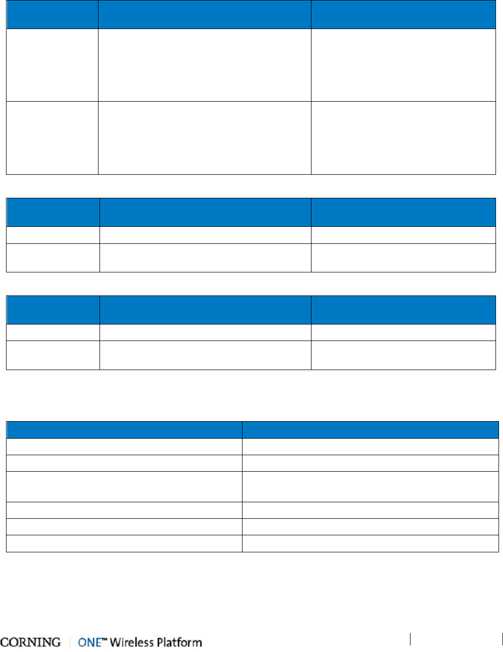
1.3.2.2 Safety and Regulatory Approvals
The safety and regulatory specifications listed below are relevant to all ONE™ devices.
Regulation/Standard
Category
Approval
Laser Safety FDA/CE 21 CFR 1040.10 and 1040.11 except for deviations pursuant to laser notice no.
50 (July 26, 2001) and IEC 60825-1, Amendment 2 (January 2001)
EMC CE EN 301 489, EN55022, EN 61000
FCC 47 CFR Part 15, 22, 24, 27
Safety
UL 60950
CAN/CSA-C22.2 No.60950-1-03
Fire Safety UL 2043 (Applicable for Antenna Unit Only)
Table 1-2. Safety and Regulatory Approvals
1.3.3 Power Consumption of Units
This section summarizes to power requirements of all ONE™ RF and digital coverage devices.
1.3.3.1 General Power Safety Instructions
• Use only UL approved power supplies.
• Use only the power cables (AC and DC) and any other relevant accessories provided with the unit to connect the power
supply to the ONE™ units.
• All devices connect to 110 to 240VAC power source.
RF Head End Units Power Consumption for Full
Chassis
HEU Chassis with 12 RIMs and 2 RIX:
200W
OIU Chassis with 12 OIMs and 2 OIX:
300W
Table 1-3. RF Headend Units Power Consumption
RF Remote End Units Max. Power Consumption
RAU (alone) 31W
RxU 21.5W
Table 1-4. RF Remote End Units Power Consumption
Digital Remote End Units Power Consumption
GEM installed in RAU 4.5W
GEM installed in Docking station 4.5W
Table 1-5. Digital Path Remote End Power Specifications
Introduction
P/N 709C011801
Page 16
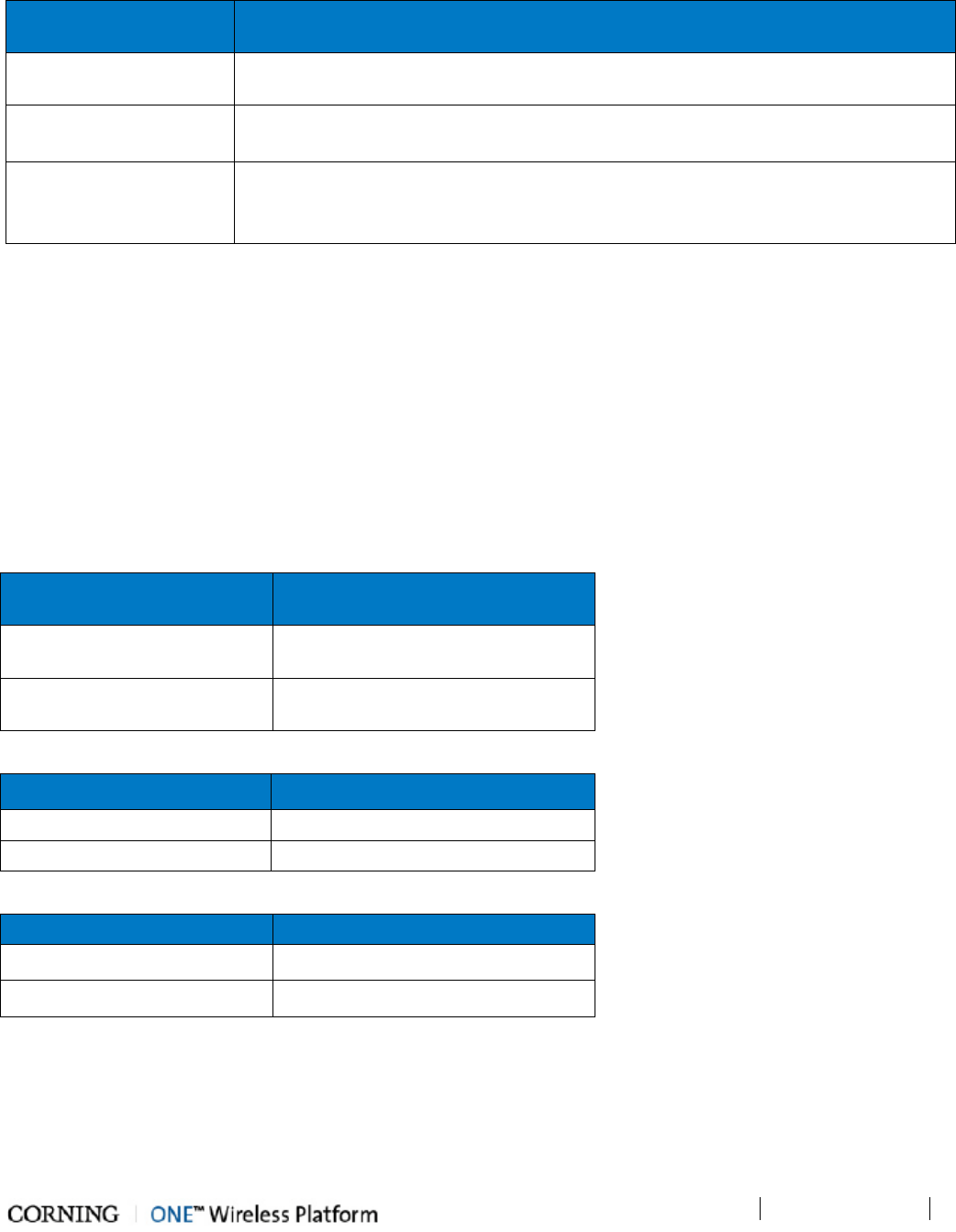
1.3.4 Dimensions and Weight of Units
The tables below describe the physical specifications of the ONE™ units.
Table 1-6. RF Path Headend Units
Unit Dimensions (H x W x D) US
[International]
Weight: lbs [kg]
HEU 7 x 17.3 x 18.95 in [177.8 x 440 x 481.7 mm]
Chassis: 37 lbs [16.8 kg]
Per RIM: 1.9 lbs [0.9 kg]
Per RIX: 1.54 lbs [0.7 kg]
HCM: 2.2 lbs [1.0 kg]
PSM: 1.98 lbs [0.9 kg]
OIU 7 x 17.3 x 18.95 in [177.8 x 440 x 481.7 mm]
Chassis: : 37 lbs [16.8 kg]
Per OIM: 0.7Kg [1.5lbs]
Per OIX: 1.54 lbs [0.7 kg]
ACM: 2.2 lbs [1.0 kg]
PSM: 1.98 lbs [0.9 kg]
Table 1-7. RF Path Remote Units
Unit Dimensions (H x W x D) US
[International]
Weight: lbs [kg]
ICU 17 x 15 x 19.2 in [430.5 x 379.8 x 488 mm] 5.5 lbs [2.5 kg] – without PSM
RAU (including
mounting bracket)
13.1 x 13.1 x 4 in [332.7 x 332.7 x 101.6 mm]
RAU only = 7.05 lbs [3.2Kg];
RAU+RxU+GEM = 14 lbs [5.5 Kg]
Table 1-8. Digital Path Units
Unit Dimensions (H x W x D) US
[International]
Weight: lbs [kg]
GEM
1.28 x 3.79 x 5.95 in [32.7 x 96.3 x 151.3 mm]
1.1 lbs [0.5 kg]
GEU-S 5.01 x 10.51 x 3.26 in (including mounting
bracket) [127.5 x 267 x 83 mm]
2.64 lbs [1.2 kg]
1.3.5 Optical Specifications
Parameter Specification
Optical Output Power <9 dBm
Max. Optical Budget 5 dB
Optical Connector OIM: MTP connector
RAU: LC/APC SM
Fiber Type Corning SMF-28 or Compatible
Wavelength 1310±10nm (Standard)
Maximum Distance (headend to remote end) 2Km (SMF)
Table 1-9. Optical Specifications
Introduction
P/N 709C011801
Page 17
1.3.6 Default Network and User Settings
1.3.6.1 Default Network Parameters
The following table identifies the default settings for each of the Network Ethernet ports located on the front panel of the HCM.
Port Name Configuration
LOCAL
DHCP: off
IP: 193.168.1.1
Subnet Mask: 255.255.0.0
LAN
DHCP: Client, or Static IP (default)
IP: 192.168.1.1
Subnet Mask: 255.255.0.0
Internal
DHCP: server on (this local port is set by default set to act as a DHCP Server and provide an
IP address to the connected computer so no configuration of the computer is required)
IP: 11.0.0.1
Subnet Mask: 255.0.0.0
Table 1-10. Default Network Port Parameters
1.3.6.2 System Administrator or "Super User"
One System Administrator or "Super User" is available. This user has the highest access level, does not belong to any group and
is the only user that can create groups.
NOTE: Upon initial login, the System Administrator should create user groups. Each new group created along with a default
Group Administrator.
User Name admin (cannot be modified)
Password default provided by Corning (and should be changed immediately)
Group none (leave blank)
Table 1-11. User Default Info
1.3.6.3 Default Group Admin
Groups can only be created by the Admin user. As a group is created, a default Group Administrator is automatically generated
for that group. The Group Administrator User Name and Password are based on the group name. For example, if the group is
named 'accounting', the default Group Administrator name will be accounting_Admin (note capital ‘A’ in Admin).
The Group Administrator is authorized to create and manage the users for his/her group. See section group passwords for
detailed description of default group_ Admin user.
Introduction
P/N 709C011801
Page 18
1.4 Installation Guidelines
The following installation assumes that site survey and installation planning (including power requirements) have been
completed. This includes planning the distribution of antennas to provide the required coverage, as well as planning the layout
of the devices and cables in the telecom closet or shaft.
1.4.1 Rack Mount Procedure
These guidelines are relevant to the system components which are installed in 19-in communication racks:
• RF Path components: HEU, OIU and ICU
• Digital Coverage components: CEU
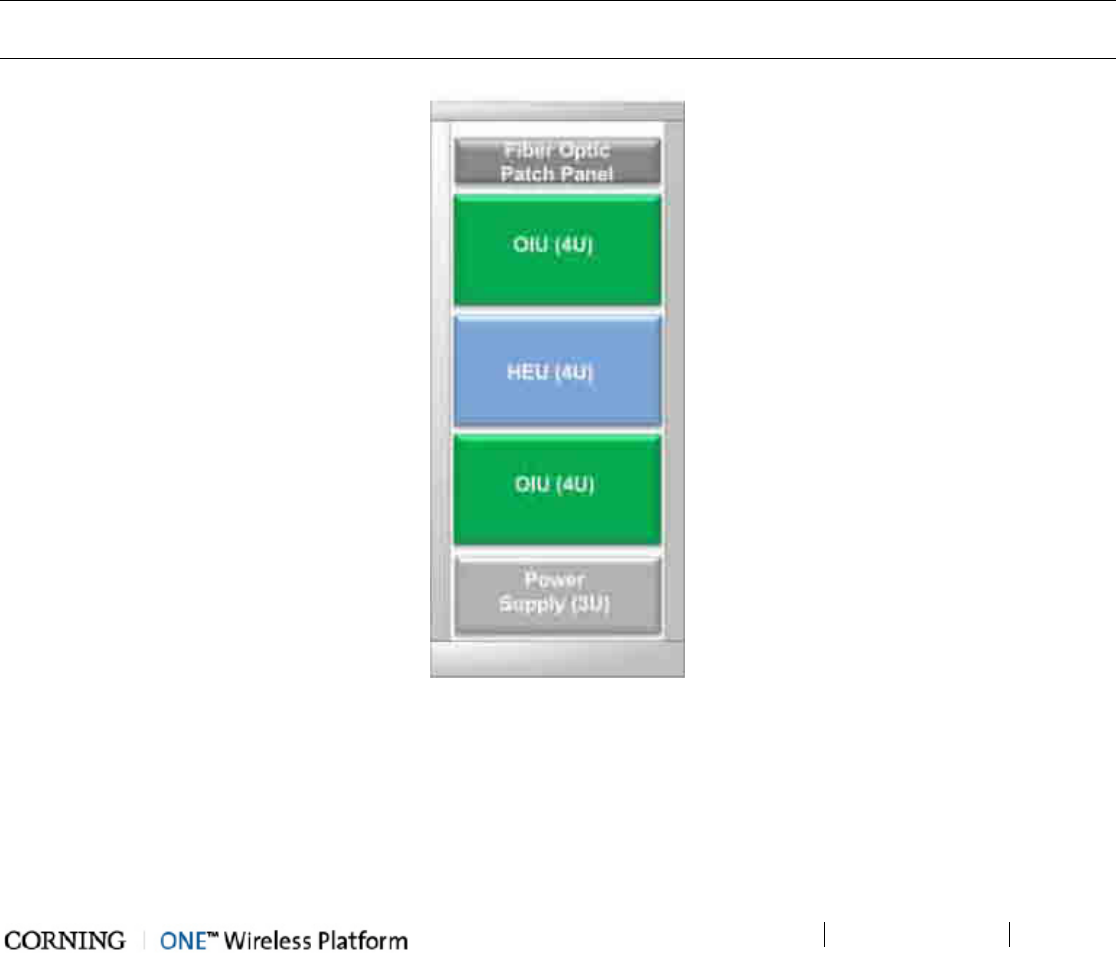
1.4.1.1 General Instructions
Verify that the rack height can support all the units to be installed, where you may also want to consider future installations. The
figure below illustrates the recommended physical location of the headend elements in the rack, so as to facilitate and simplify
the cabling connections.
NOTE: The configuration is for a single operator. If the site is serviced by more than one operator, each operator often installs
their equipment in a separate rack.
Figure 1-2. Example of Communication rack Installation

Introduction
P/N 709C011801
Page 19
1.4.1.2 Rack Installation Safety Instructions
The following guidelines help ensure your safety and protect the equipment from damage during the installation.
• Only trained and qualified personnel should be allowed to install or replace this equipment.
• Verify that ambient temperature of the environment does not exceed 50°C (122°F)
• If installed in a closed or multi-unit rack, the ambient temperature of the rack environment must be taken into consideration
in terms of exceeding the maximum rated ambient temperature (indicated in the previous item).
• To maintain a low center of gravity, ensure that heavier equipment is installed near the bottom of the rack and load the rack
from the bottom to the top.
• Ensure that adequate airflow and ventilation within the rack and around the installed components so that the safety of the
equipment is not compromised. It is recommended to allow for at least about 2 cm of airspace between devices in the rack.
• Verify that the equipment is grounded as required – especially the supply connections.
1.4.2 Power Consumption, Connections and Power Supplies
1.4.2.1 Power Safety Instructions
SAFETY WARNINGS!!!! When installing or selecting the power supplies:
• Be sure to disconnect all power sources before servicing.
• Calculate the required power according to the requirements of the specific installation and then determine the configuration
of the power supplies. The required DC cables will then be determined by the selected PS configuration.
• Use only UL approved power supplies
• Install external over-current protective devices for the system according to the requirements described in Power
Consumption of Units section (on page 15).
1.4.2.2 Types of Power Supplies
CMA supplies various power supplies that can be installed in a rack or mounted on a wall, depending on your configuration.
1.4.2.3 Circuit Breakers
Calculate the required fuse protection while referring to Power Consumption of Units section (on page 15). Also, when
Install fuse protections for the system taking into account that there may be other CMA system elements that require external
fuse protection.
Introduction
P/N 709C011801
Page 20
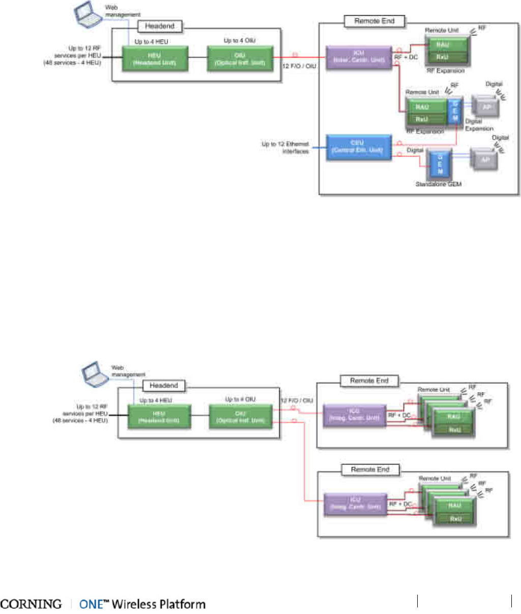
1.5 System Architecture and Topologies
The ONE™ solution fiber-optic infrastructure is used to transmit both RF and digital services:
• RF services – fiber-optics infrastructure transfers converged wireless services from the headend towards Remote Antenna
Units (RAU) deployed at the remote end locations according to user defined configuration.
• Digital services – fiber-optics infrastructure transfers Digital services from the corporate LAN to Gigabyte Ethernet Modules
(GEM) and then 3rd party equipment deployed on each floor.
Figure 1-3. ONE™ Solution Basic Architecture
1.5.1 RF Path
At the headend, RF signals from the RF signal sources (e.g. BTS/BDA) are conditioned by service specific (conditioner) modules
in the HEU (Headend Unit) and organized into (up to three) user configurable sectors. The conditioned RF signals are converted
to optic signals by the (wideband) OIU (Optic Interface Unit) and specific sectors are routed towards selected remote locations
according to user defined configurations.
The optic fibers at the OIU are routed to the ICU (Integrated Centralized Unit) at the remote end. From the ICU the optic fibers
are distributed along with DC to the Remote Antenna Units (RAU).
Figure 1-4. RF coverage Architecture
Introduction
P/N 709C011801
Page 21
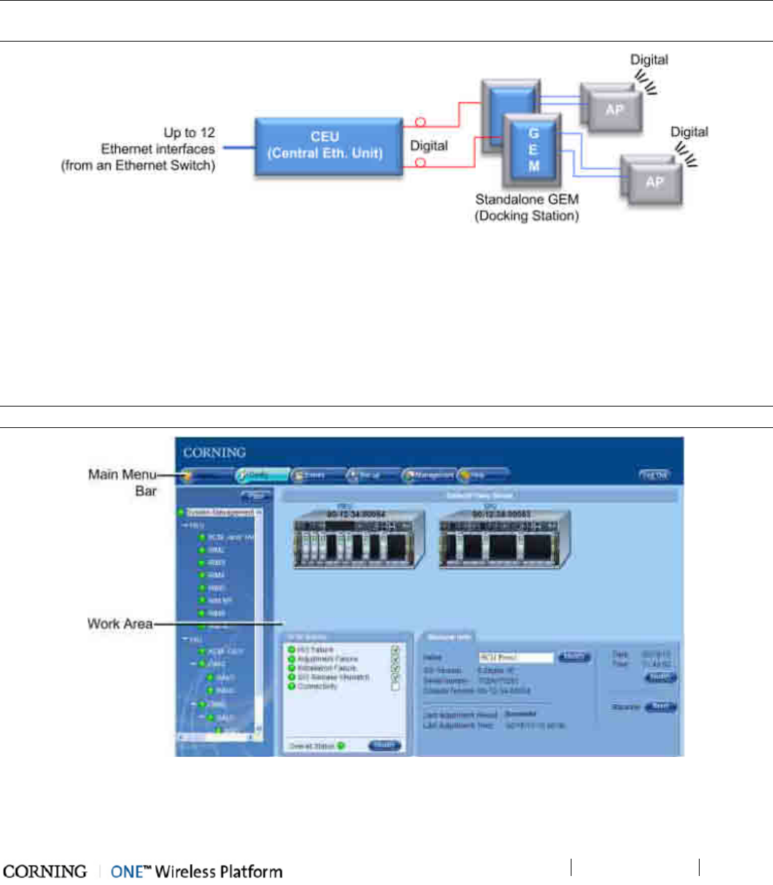
1.5.2 Digital Path
The Digital services from the corporate LAN (received via Ethernet Switch) are converted to optic signals by the CEU (Centralized
Ethernet Unit) and routed over optic fibers towards the GEM units. The optical traffic is then converted to 1GbE by the GEM
(Gigabit Ethernet Modules) modules and distributed to two third party equipment such as Access Points, Ethernet switch, etc.
NOTE: GEMs can be connected to the CEU either directly, or via an ICU (described under RF Path (on page 20)). In that case,
the ICU can also provide DC to the GEMs.
Figure 1-5. ONE™ Solution Digital Path Architecture
1.6 ONE™ WEB Management Application
The ONE™ solution consisting of the HEU and its hosted elements is managed via a WEB session to the HEU. The GUI based WEB
management application provides all the required configuration, management and monitoring options for the ONE™ system.
The ONE™ Web management application consists of the Main Menu bar, where the displayed side-bar and work area options
vary according to the selected menu option.
NOTE: The available tabs and capabilities vary depending on the access level used to open your session.
Figure 1-6. Main Window (Config Tab - Default Display)
Introduction
P/N 709C011801
Page 22
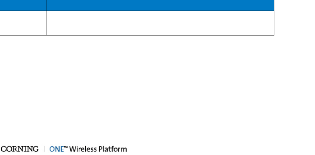
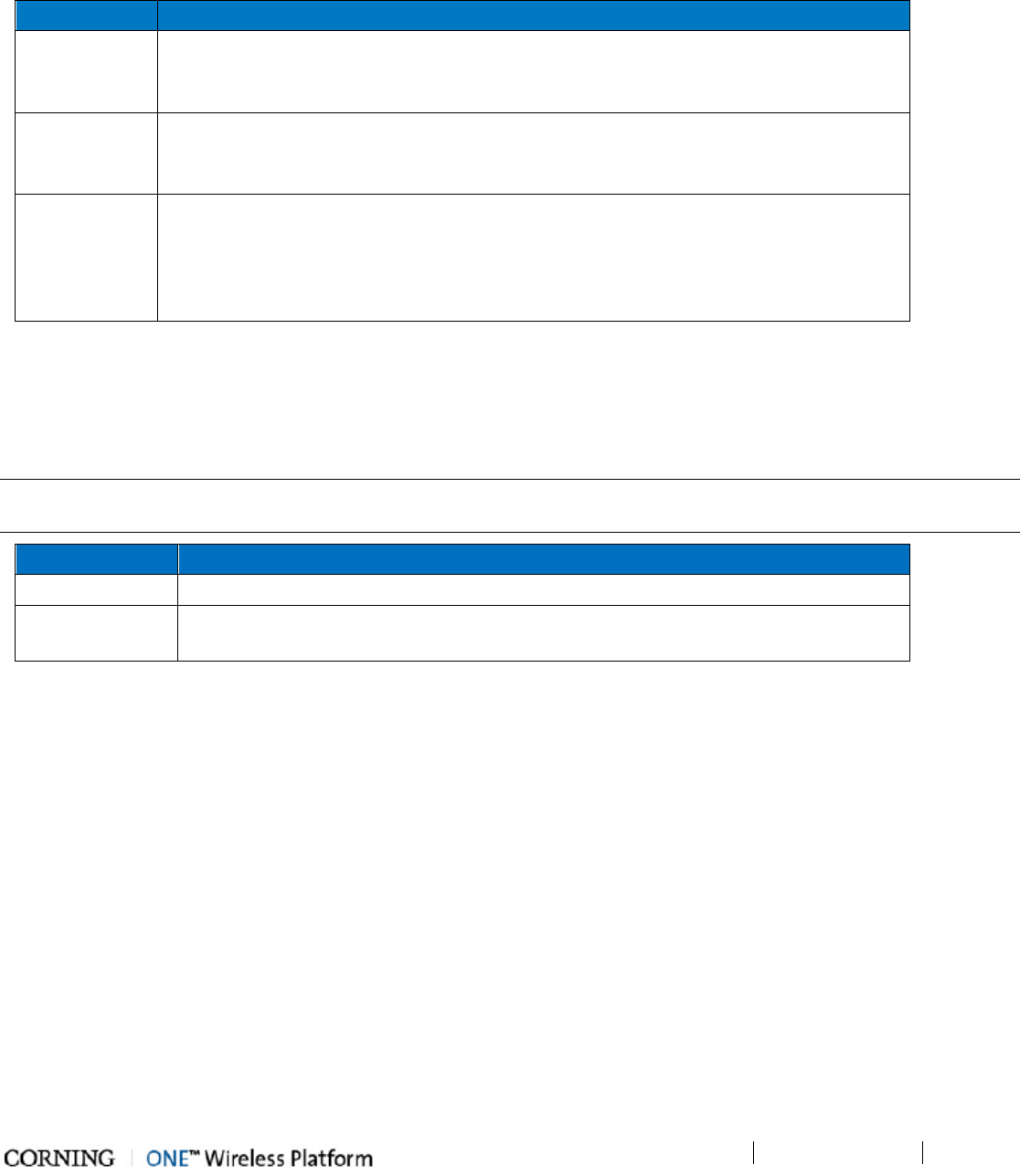
The Main Menu Bar includes the following tabs:
Tab Description
Monitor N/A
Config Displayed upon login by default. Displays general module information and
device alarms and provides the configuration options for the available
selected site devices. A brief description is given in Overall Device
Display - Config Tab (on page 22). A detailed description is given in
Device Configuration section (on page 91).
Events Displays the events that occurred on the monitored devices and enables
generating reports. Configuration changes that are initiated by the network
manager are not considered events display. See Events Display section.
Set-up Set-up tool used for initial system set-up, commissioning of system devices
and adjustment procedure. See About the System Setup Tool section (
on
page 74) for details.
Management Provides administration options such as firmware upgrade, user management
options and IP settings required for receiving traps.
Help Provides access to Online Help
Table 1-12. Main Menu tabs
Introduction
P/N 709C011801
Page 23
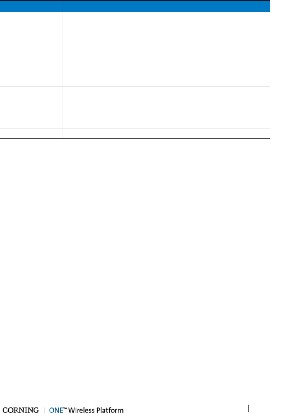
1.6.1 Overall Device Display - Configuration Tab
The Config window is displayed by default upon login and includes the following for each selected element:
• Network Topology Tree - hierarchically displays the connected and available site devices and their status.
• Device Configuration Tabs - device specific which include the configurable parameters (e.g. service control, RF parameters)
and general information (e.g. device name, Firmware version)
• Device View - visualization of device, with LEDs corresponding to the device status. Device view can be used for fault
sourcing at a glance.
• Alarms - displays the device alarms for fault sourcing and provides alarm masking options
Note the following:
• The device selected in the Network Topology Tree appears green in the Device View Mode area
• Point to module in Device View to display property info
Figure 1-7. Config Tab
1.6.2 Session Access
• Number of simultaneous sessions - the HCM supports up to three simultaneous sessions for multiple users (local/remote
access).
• Login Priorities - the login of users is enabled according to priority – when the maximum amount of multiple users are logged
in, the HEU terminates the session running for the lowest level user logged in the longest (user receives alert message and
force logout is performed) in order to enable a higher access level user to login to the system. A message indicating logon
denial appears when the maximum number of users is logged in and a lower level user attempts to log in to the system.
Introduction
P/N 709C011801
Page 24
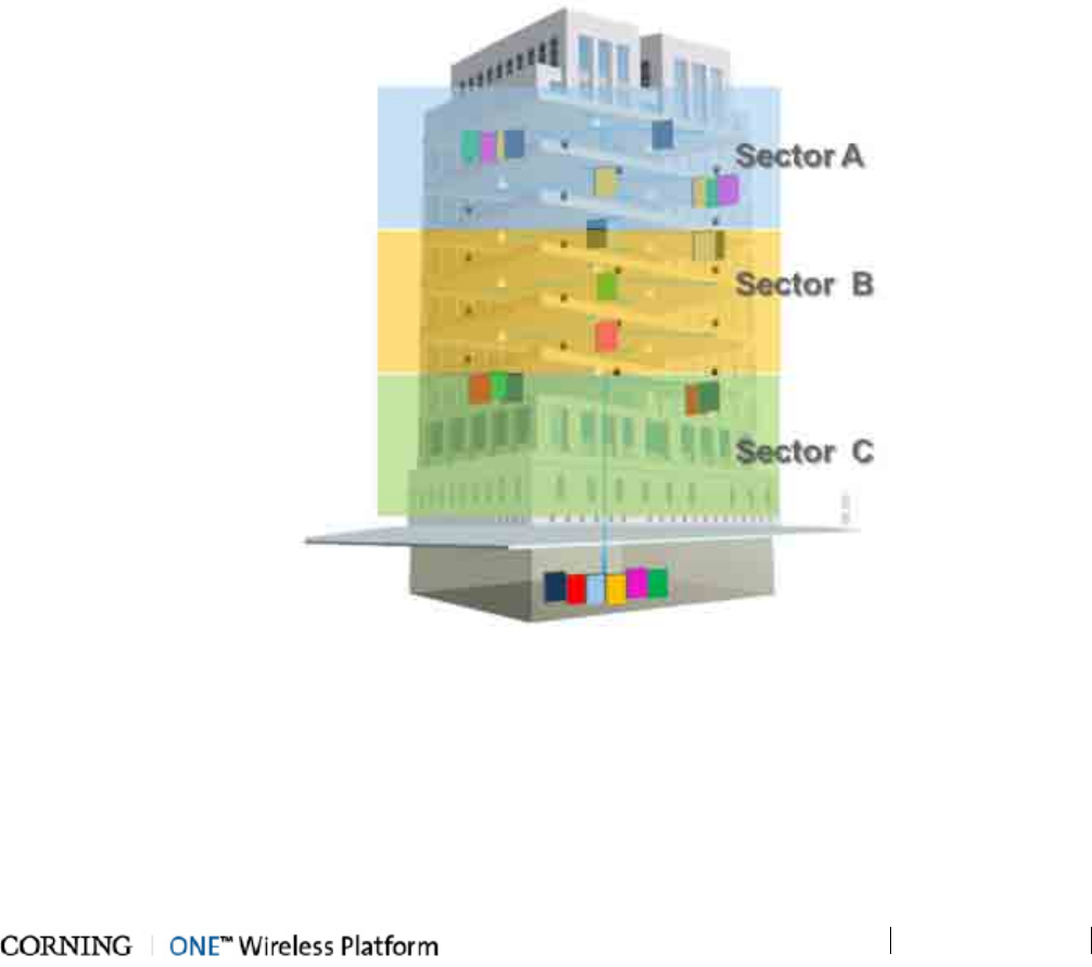
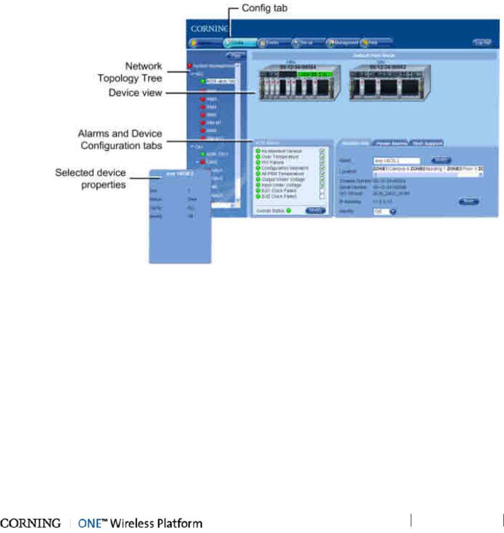
1.7 User Controlled Sectorization
ONE™ fiber-optics infrastructure allows various combinations of SISO and MIMO services to be routed from the headend to
specified remote locations on each floor, according to user defined configurations. This allows optimizing service coverage and
provides equipment savings. While the fiber-optics infrastructure is common, the services can be routed via service provider
shared or dedicated equipment. By default, the system is configured to support a single sector: all services are transferred to all
remote locations. This default configuration can be easily modified according to site requirements.
The following figure illustrates service distribution from the head-end to various locations on ach remote floor. Each color
represents a specific service, where different combinations of services are distributed at various locations on the same floor
according to coverage requirements.
Figure 1-8. Illustration of Sectorization
Introduction
P/N 709C011801
Page 25
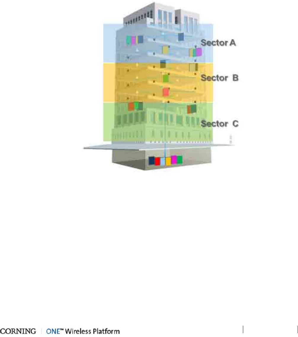
1.7.1 MIMO Configurations
MIMO topologies provide more density by using two independent RF paths for the same service, where the independent paths
are implemented by dedicated modules along the path.
MIMO configuration is implemented by routing the two RF bands over dedicated RF paths at both the entry point (in the Headend
Unit) and at the exit point (at the Remote Unit). Note that the Optical Interface Unit is wideband and the services are combined
in a single OIM for routing to the same Remote End Unit. At the Remote End Unit, the services are distributed by two dedicated
modules.
NOTE: MIMO configuration can also be implemented by two separate Remote End Units.
Figure 1-9. Example of MIMO Configuration
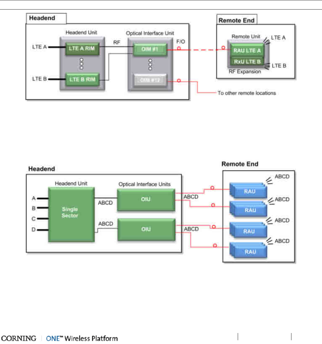
1.7.2 Single Sector Example
In this example, all four services (A,B,C,D) are routed to all (up to 72) remote locations. In the illustrated topology, a single HEU
conditions the services and feeds them to two OIU systems for conversion to optic signals. Each OIU supports up to 36 RAU
(Remote Antenna Units).
Figure 1-10. Single Sector Configuration
Introduction
P/N 709C011801
Page 26
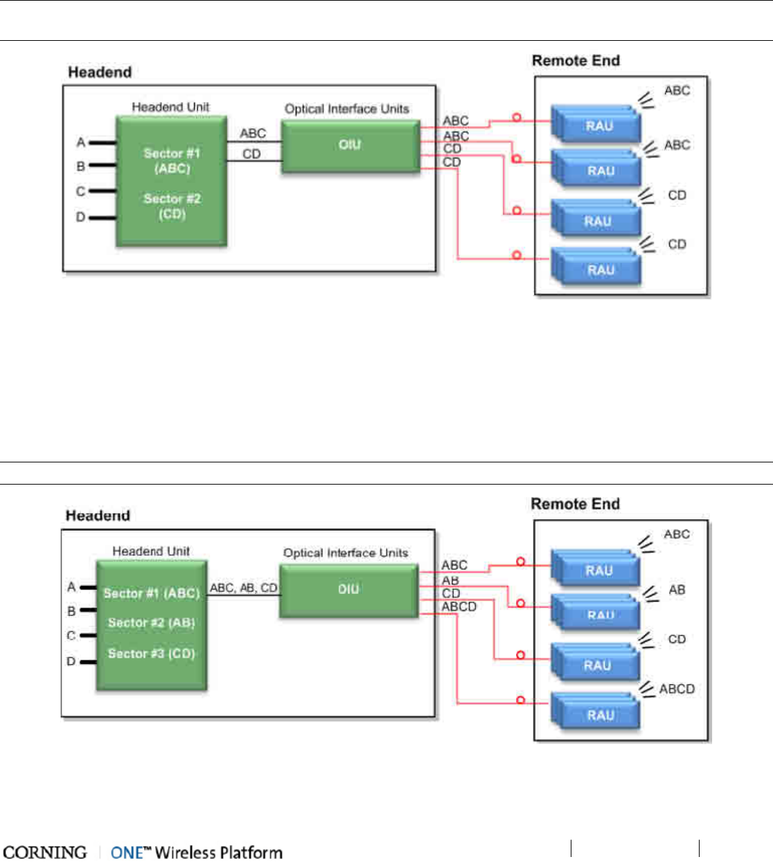
1.7.3 Dual Sector Example
In this example, two sectors (groups/layers) of services are defined: A,B,C and C,D. Note that a service can be allocated to any
of the sectors at the same time. For example, service C is allocated to both Sectors. Both sectors are routed to the OIU for optic
conversion. Each OIU module (OIM) can be configured to support either one or (if they do not have a common band) to both
sectors and the corresponding services are routed from the OIM to its hosted RAU units.
NOTE: In the example below, band C is common to both Sector #1 and #2; therefore, an OIM cannot be assigned both sectors
(i.e. ABC + CD).
Figure 1-11. Example of Dual Sector Configuration
1.7.4 Tri-sector Example
In this example, three sectors (groups/layers) of services are defined: ABC, AB,CD. Note that a service can be allocated to any
of the sectors at the same time. For example, services C and B are allocated to two of the sectors. The sectors are routed to
the OIU for optic conversion. Each OIU module (OIM) can be configured to support either one, two or three sectors in any
combination and the corresponding services are routed from the OIM to its hosted RAU units.
NOTE: An OIM cannot support two sectors that have a common band (e.g. ABC and BC, or ABC and CD).
Figure 1-12. Example of Tri-sector Configuration
Introduction
P/N 709C011801
Page 27
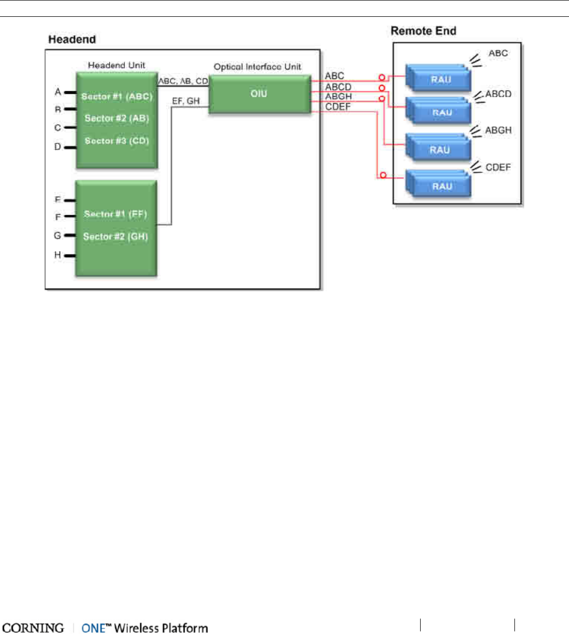
1.7.5 Tri-sector Example with Two HEUs
This tri-sector example supports two HEUs. In this topology, one HEU supports three sectors (groups/layers) and the other two
sectors for a total of five sectors. These groups of services are all routed towards a common OIU. Each OIU module (OIM) can
be configured to support any (legal) combination of sectors and the corresponding services are routed from the OIM to its hosted
RAU units.
NOTE: Multiple sectors allocated to the same OIM cannot share any identical frequency bands.
Figure 1-13. Example of Tri-sector Configuration with Two HEUs
Unit Descriptions - RF Path
P/N 709C011801
Page 29
2 Unit Descriptions - R F P ath
This chapter provides detailed descriptions of the ONE™ solution components. The descriptions are organized according to RF
and Digital path headend and remote end components. This includes port and LED interface descriptions.
2.1 RF Path - Headend Components
ONE™ RF Path coverage solution includes the following headend elements:
• HEU – Headend Unit
• OIU – Optical Interface Unit
Figure 2-1. RF Path Headend Components
2.1.1 HEU (Headend Unit)
The HEU performs the following main functions:
• Conditions (up to 12) RF sources to a level required for feeding to the Optical Interface Unit (OIM).
• Enables the configuration of up to three sectors consisting of groups of RF services.
• Provides single source control and management of the ONE™ solution RF path.
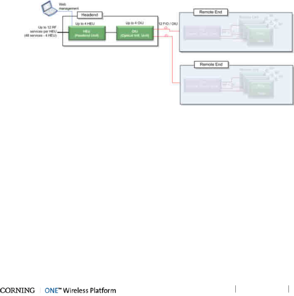
Each HEU supports up to 12 services. For additional services or density, two or more HEU units can be cascaded in a
Master/Slave configuration that is managed from the Master HEU. For HEU installation procedure, see section Installation –
RF Path Elements (on page 45).
Unit Descriptions - RF Path
P/N 709C011801
Page 30
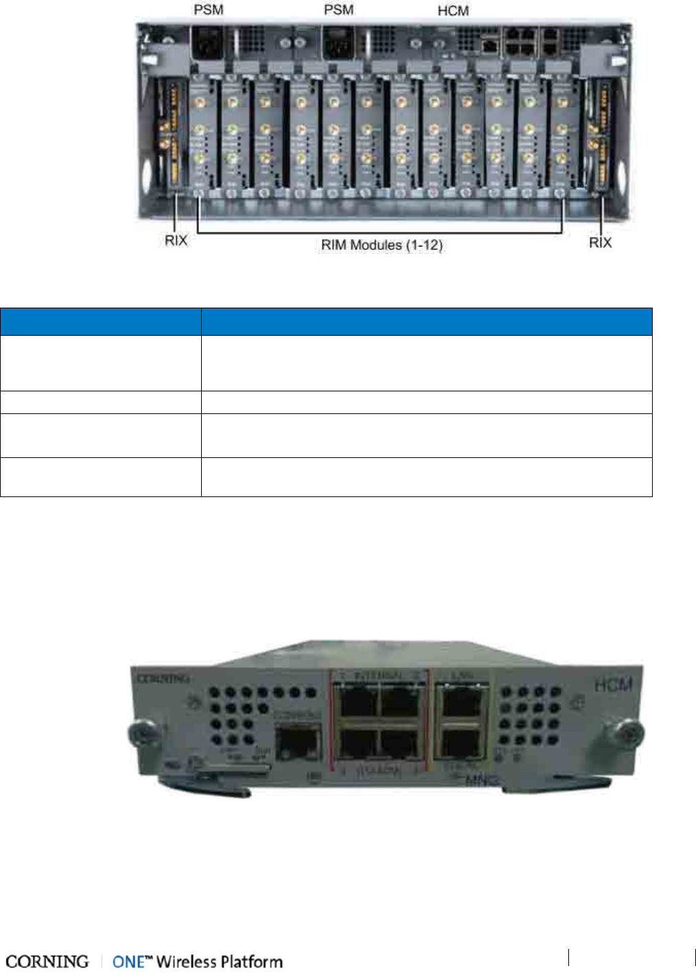
Figure 2-2. HEU Front Panel with Installed Modules
Module Description
HCM (Headend Control
Module) (on page 30)
Provides system management and control functions. In Master/Slave
configurations, HCM is installed in the Master and ACM (on page 34) in
the Slave.
PSM (Power Supply Modules) 110-230VAC. If two are installed, both must be powered on.
RIX (RF Expander Module) – Service specific conditioner units.
OIX (Expander Module (on
page 32)) Used to interface with the parallel Expander Unit on the HEU.
Table 2-1. OIU Front Panel Interface Definitions
2.1.1.1 HCM (Headend Control Module)
The HCM provides management and control capabilities for the ONE™ system. Each INTERNAL port is dedicated to a single OIU
(see OIU (on page 33)) management connection. The HCM module includes Local and LAN management ports and LED status
indicators.
Figure 2-3. HCM Module
Unit Descriptions - RF Path
P/N 709C011801
Page 31
Port Description
INTERNAL (TO ACM) [4] RJ45, 100Mb Ethernet ports -
used for management of connected OIU systems
(and/or HEU Slaves).
LAN RJ45, 1Gb Ethernet port - connects to the corporate LAN for remote management
LOCAL RJ45, 1Gb Ethernet port - local configuration and management
CONSOLE RJ45, serial port - local configuration for service personnel
SD Card Slot Supports uSD cards up to 32GB (used for example for saving configuration files)
Table 2-2. HCM Ports
LED Description
PWR Steady Green - Power supplied to unit
Off – No power is supplied to the unit
RUN
Steady Green – HCM Boot up sequence complete and functioning
Blinking Green – HCM Boot up sequence in process
Off – No power supplied to the unit
SYS Indicates overall status of the managed system
FAN Green – Normal operation status
Red – Faulty fan (s)
Table 2-3. LED Description
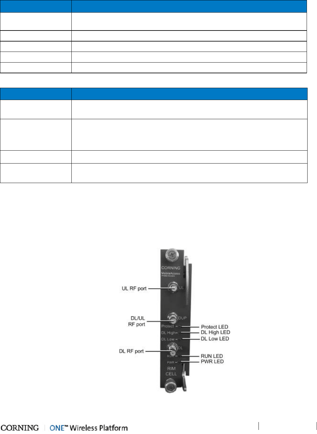
2.1.1.2 RIM/RIM-M (RF Interface Module)
Up to 12 service specific conditioning modules are installed in the HEU chassis. Each RIM supports both Simplex and Duplex RF
connectors. RIM-M modules support MIMO services (e.g.700 MHz LTE, AWS). LEDs provide status indications on signal level and
module operation.
Figure 2-4. RIM Module
Unit Descriptions - RF Path
P/N 709C011801
Page 32
The following tables provide a description of the RIM ports and LED status indicators.
Port Description
DL/UL UL and DL simplex connections to the RF signal source
DUP Duplexed UL and DL connection to the RF signal source
Table 2-4. RIM Ports Description
LED Description
Protect
Green – RF signal is at normal level
Red (Blinking) - Indicates the RF signal is too high and that the protection
mechanism is enabled
DL High Provides indication on DL RF level in conditioner module:
Red – Signal is 2 dB above max. expected power
DL Low Provides indication on DL RF level in conditioner module::
Red – No signal or 15 dB below max. expected power
RUN
Steady Green - Power on and module SW has initialized and is up and
running
Blinking Green- Fault detected (e.g. RIM module SW halted) orSW
upgrade in process
Off - No power
PWR On - Input power is within required range
Table 2-5. RIM LED Descriptions
Unit Descriptions - RF Path
P/N 709C011801
Page 33
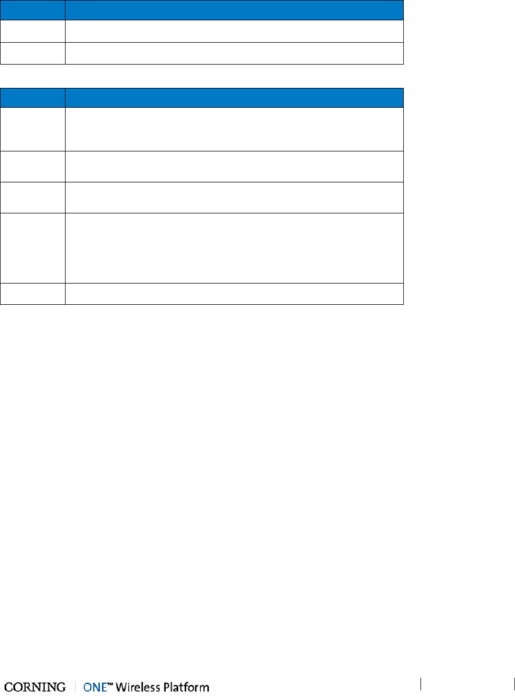
2.1.1.3 RIX (RF Expander Module)
The RIX Expander module provides the RF interface to the OIU unit. Two RIX Expander modules can be installed in each HEU
chassis, to support up to four OIU (per HEU). If only one Expander module is installed, it is required to terminate the empty slot
with the supplied termination.
NOTE: The OIU Expander Modules are similar in appearance to the HEU Expander modules but are NOT INTERCHANGEABLE.
Each Expander module is indicated as RIX or OIX on the bottom of the module.
Figure 2-5. RIX Expander Module Interfaces
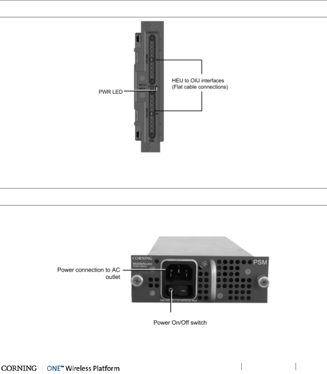
2.1.1.4 PSM (Power Supply Module)
NOTE: The Power Supply modules and installation are the same for the HEU and OIU chassis. If two power supplies are
installed, both must be switched ON to begin system operation.
The HEU (and OIU) chassis can support two power supply modules (110-240VAC), where the second power supply provides
redundancy in case one of the supplies fails. If two modules are installed, both must be connected to the AC outlet and turned
on at all times.
Figure 2-6. Power Supply Module
Unit Descriptions - RF Path
P/N 709C011801
Page 34
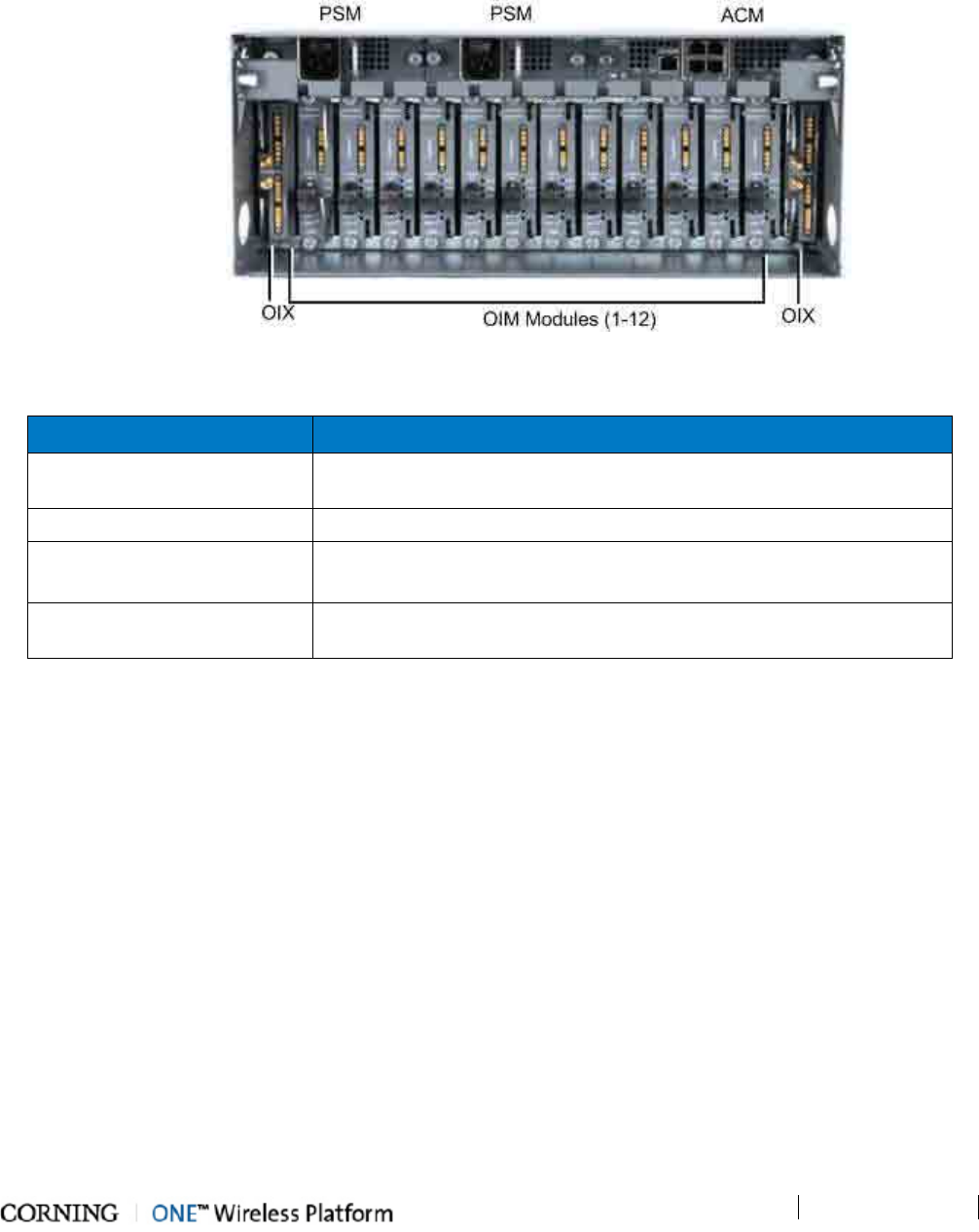
2.1.2 OIU (Optical Interface Unit)
The OIU interfaces to the HEU, performs the RF to optic conversion of the received signal and distributes the wireless RF services
to the RAU units over the fiber optic infrastructure to the remote site. Each OIU supports up to 12 SM optic fibers (one fiber per
OIM), which are routed to up to 36 RAU (three Remote Antenna Units per OIM).
Figure 2-7. OIU Front Panel with Installed Modules
Module Description
ACM (Auxiliary Control
Module) (on page 34).
Auxiliary Control Module – interfaces with the HEU's HCM to provide
remote management capabilities.
PSM (Power Supply Modules) 110-230VAC. If two are installed, both must be powered on.
OIM (Optical Interface
Module) (on page 35) Wideband, optical to RF (and vice versa) conversion units.
OIX (Expander Module (on
page 32)) Used to interface with the parallel Expander Unit on the HEU.
Table 2-6. OIU Front Panel Interface Definitions
Unit Descriptions - RF Path
P/N 709C011801
Page 35
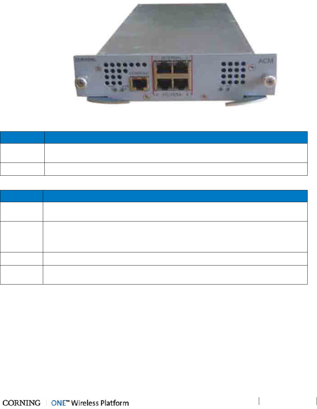
2.1.2.1 ACM (Auxiliary Control Module)
The ACM provides basic control functions (only) for the host chassis via a local connection. The ACM module can be remotely
managed via an HCM (on page 30) connection.
Figure 2-8. ACM Module
Port Description
INTERNAL
(TO HCM) [4] RJ45, 100Mb Ethernet ports used for OIU and/or HEU slave management connections
Console [1] RJ45, serial port used for basic IP configuration and local connection for service personnel
Table 2-7. ACM Ports Description
LED Description
PWR Steady Green - Power supplied to unit
Off – No power is supplied to the unit
RUN
Steady Green – HCM Boot up sequence complete and functioning
Blinking Green – HCM Boot up sequence in process
Off – No power supplied to the unit
SYS Indicates overall status of the managed system
FAN Green – Normal operation status
Red – Faulty fan (s)
Table 2-8. ACM LED Indicators Description
Unit Descriptions - RF Path
P/N 709C011801
Page 36
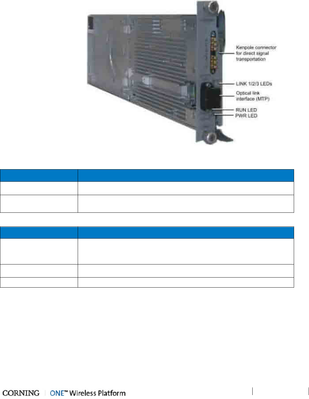
2.1.2.2 OIM (Optical Interface Module)
The OIM is a wideband RF to F/O (and vice-versa) media conversion module. Up to 12 OIM units can be installed in each OIU,
where each OIM can support up to three Remote Antenna Unit (RAU) connections.
Figure 2-9. Optical Interface Module
Port Description
Optical Link MTP Connector for optical interface connection; SMF
Expansion [6] Kenpole connector for 1:1 direct signal transportation, 3 UL and 3 for DL
Enables (DL and UL) broad band connection to each optical link
Table 2-9. OIM Ports Description
LED Description
Link 1-3
ON - the optical link to/from the connected remote functions within the
specifications in both directions.
Blinking - optical power from remote is lower than required
RUN Steady Green – SW Boot up sequence complete and functioning
PWR Steady Green – Power input detected for corresponding module
Table 2-10. OIM LED Descriptions
Unit Descriptions - RF Path
P/N 709C011801
Page 37
2.1.2.3 OIX (Optical Expander Module)
Each OIX Expander module provides the RF interface to up to two HEU units via two 9-pin connectors. Two OIX Expander
modules can be installed in each OIU chassis. Up to four OIU units can be hosted by an HEU. If only one Expander module is
installed, it is required to terminate the empty slot with the supplied termination.
NOTE: The OIU Expander Modules are similar in appearance to the HEU Expander modules but are NOT INTERCHANGEABLE.
Each Expander module is indicated as RIX or OIX on the bottom of the module.
Figure 2-10. OIX Expander Module Interfaces
Unit Descriptions - RF Path
P/N 709C011801
Page 38
2.2 RF Path Remote End Site Components
The RF coverage solution remote end components comprise the following elements:
• ICU (Intermediate Centralized Unit) - forwards optics along with DC to the RAU and its sub-modules.
• RAU (Remote Antenna Unit) - provides RF distribution and includes internal antennas. It can also encase data distribution
module (GEM).
• RxU (Remote Expansion Unit) - installed in the RAU. Provides support for two additonal RF services for a total of 6 services
per RAU.
Figure 2-11. RF Path Remote End Components
A detailed description of the remote end components is provided in the following sections
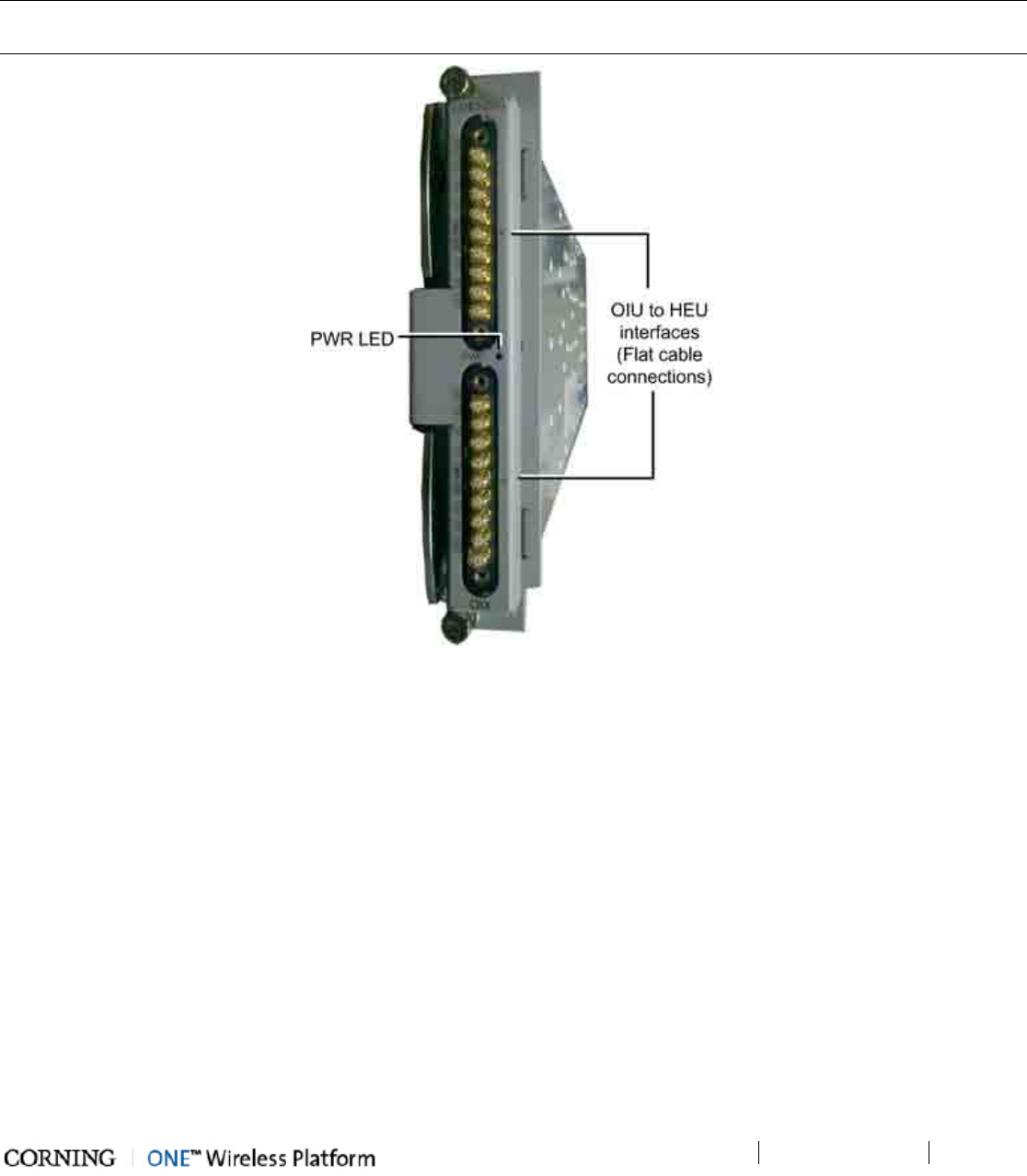
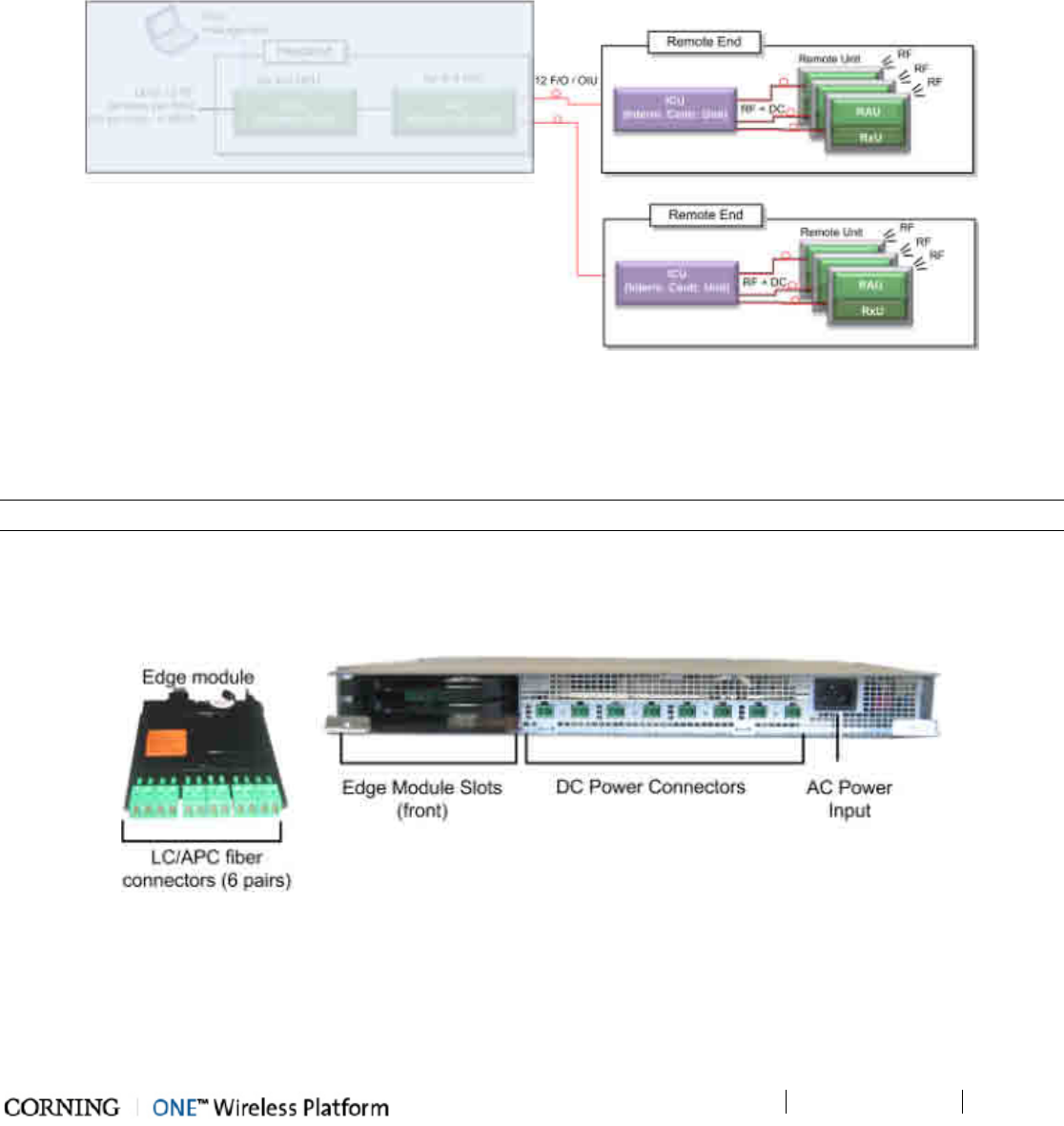
2.2.1 ICU (Intermediate Centralized Unit)
NOTE: The ICU can also be used on the digital path.
The ICU is installed at the floor level. It provides the LC/APC optical interface along with DC power to the RAU RF (and data)
sub-modules. The optical and DC signals are routed via a composite cable connected between the ICU and hosted RAU modules.
The optics signal is provided via one or two dedicated Edge modules that convert MTP optic interfaces to LC/APC interface; the
DC power is provided by up to four dedicated power supplies. A single power connection feeds all ICU power supply modules.
Figure 2-12. ICU Front Panel Interfaces and Modules
Unit Descriptions - RF Path
P/N 709C011801
Page 39
Interface Description
Power Connectors Up to eight DC power connectors, depending on number of power supply
modules installed.
LC/APC SM optics connectors implemented by up to two Edge modules inserted
from the rear: six connectors per Edge module.
AC Power Input 110-230VAC power input to unit.
Table 2-11. ICU Front Panel Interface Descriptions
Edge modules and power supplies are extracted and inserted from the rear of the unit.
Figure 2-13. ICU Rear Panel Interfaces and PSM Modules
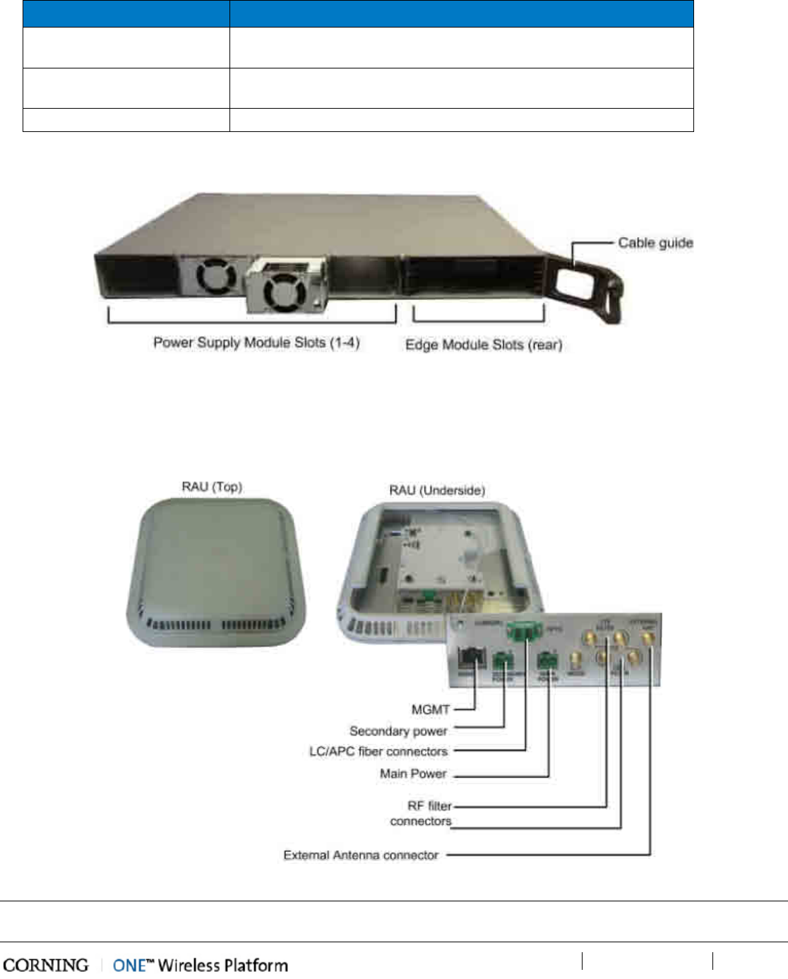
2.2.2 RAU (Remote Antenna Unit)
The RAU distributes up to four RF services via internal antennas (external antennas are optional). The RF services are received
over optic cables and converted for distribution over internal (or optionally external) antennas.
Figure 2-14. RAU Module
NOTE: The RAU enclosure can host two additional modules: RxU for MIMO support and GEM for digital coverage. See relevant
sections for details on these modules.
Unit Descriptions - Digital Path
P/N 709C011801
Page 40
Interface Description
MGMT RJ45 local management connection
PWR
DC power inputs
Main - connect to DC (from composite cable)
Secondary –
in case of PoE clients. Used when GEM modules are installed
(in addition to Main)
F/O LC/APC SM connectors for UL and DL optic connections
Listening Mode N/A
RF Filter (e.g. LTE, CELL) QMA RF ports for external cavity filter use (In/Out). For CELL and LTE
filters.
External Antenna Optional connection to broadband external antennas. Requires GUI
configuration (internal antenna is enabled by default).
Table 2-12. RAU Interfaces
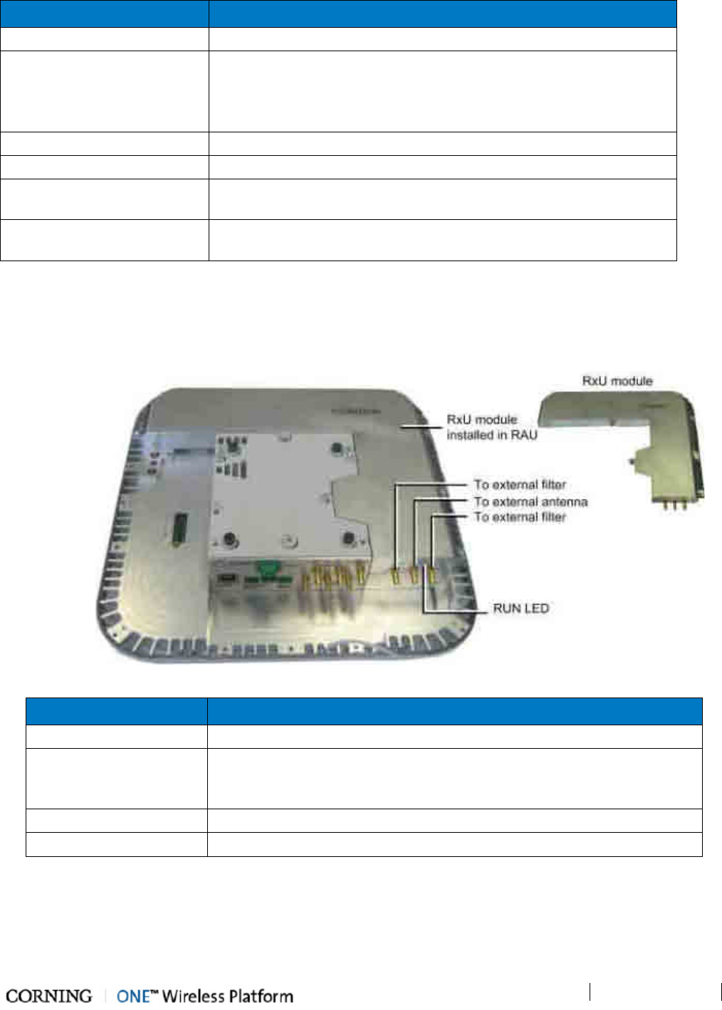
2.2.2.1 RxU (Remote Expansion Unit)
The RxU is an Add-on to the RAU which provides support for MIMO services (i.e. 700MHz LTE, AWS).
Figure 2-15. RxU Interfaces
Module Description
Filter Filter connections to the corresponding filter.
External Antenna
RF Connection to external antenna, used for above-ceiling installation.
(Both the RxU and the RAU antennas are used since this implements a MIMO
configuration)
External RF Filters QMA RF ports for external cavity filter use. For CELL and LTE filters.
RUN LED Indicates SW is up and running.
Table 2-13. RxU Front Panel Interface Connections
Unit Descriptions - Digital Path
P/N 709C011801
Page 41
3 Unit Descriptions - Digital Path
This chapter provides detailed descriptions of the Digital Path components.
3.1 Digital Path Components
The digital path comprises the following elements - located at the remote end
• CEU – Centralized Ethernet Unit
• GEM – Gigabit Ethernet Module -
NOTE: The GEM module can be installed in two configurations: in the RAU enclosure or (as illustrated below) as a standalone
unit in a Docking Station.
Figure 3-1. ONE™ Digital Path Architecture
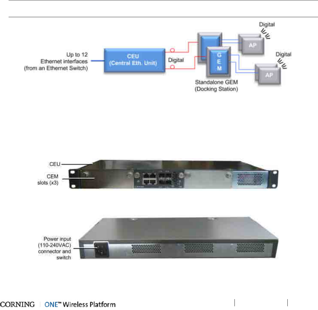
3.2 CEU (Centralized Ethernet Unit)
The CEU is a Centralized Ethernet-over-Fiber Media Converter Unit. Located at the remote end, it converts Ethernet media (from
a LAN switch) to fiber media for routing towards GEM modules. The CEU hosts three Centralized Media Converter Modules
[CEMs]. Each module supports four Ethernet ports (LAN switch connections) and four F/O connectors (towards GEM modules).
Figure 3-2. CEU Front Panel with Installed CEM Module
Figure 3-3. CEU Rear Panel
Unit Descriptions - Digital Path
P/N 709C011801
Page 42
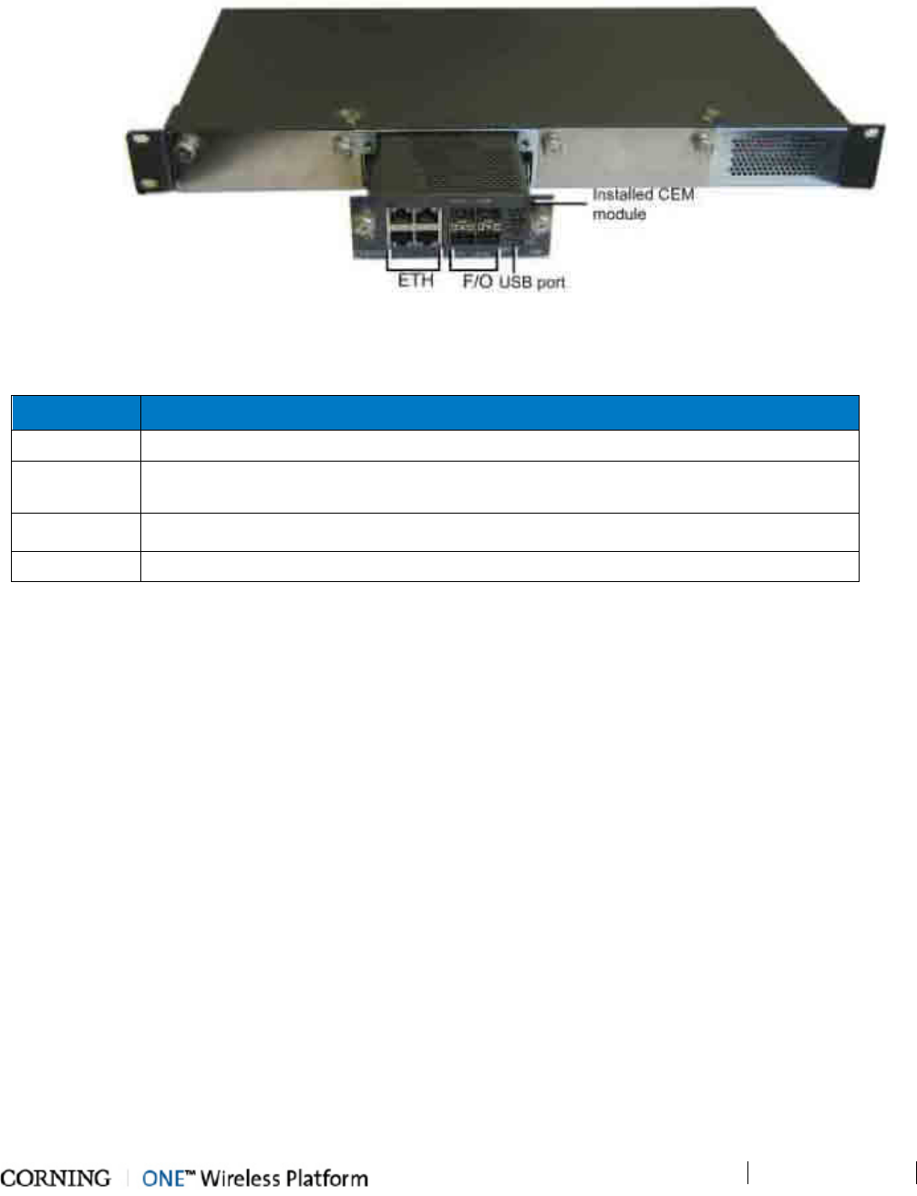
3.2.1 CEM (Centralized Ethernet Module)
The CEU supports up to three CEM modules, where each CEM supports four Ethernet ports (LAN switch connections) and four
F/O connectors (towards GEM modules). All interfaces (except for power) are located on the front panel (see section CEM).
Figure 3-4. CEM Interfaces (Installed in CEU)
The CEM module interfaces include Ethernet connections to the Ethernet switch, F/O connections and LED status indicators.
The following table provides a description of the CEM ports.
Port Description
ETH Four ETH connections to LAN switch
F/O [4] 10/100/1000BASE-T RJ-45 connectors to [4] LC/UPC fiber connectors (using SFP
–small-form pluggable module)
USB port USB serial port - service port
PWR Steady Green – Power input detected for corresponding module
Table 3-1. Ports Description
Unit Descriptions - Digital Path
P/N 709C011801
Page 43
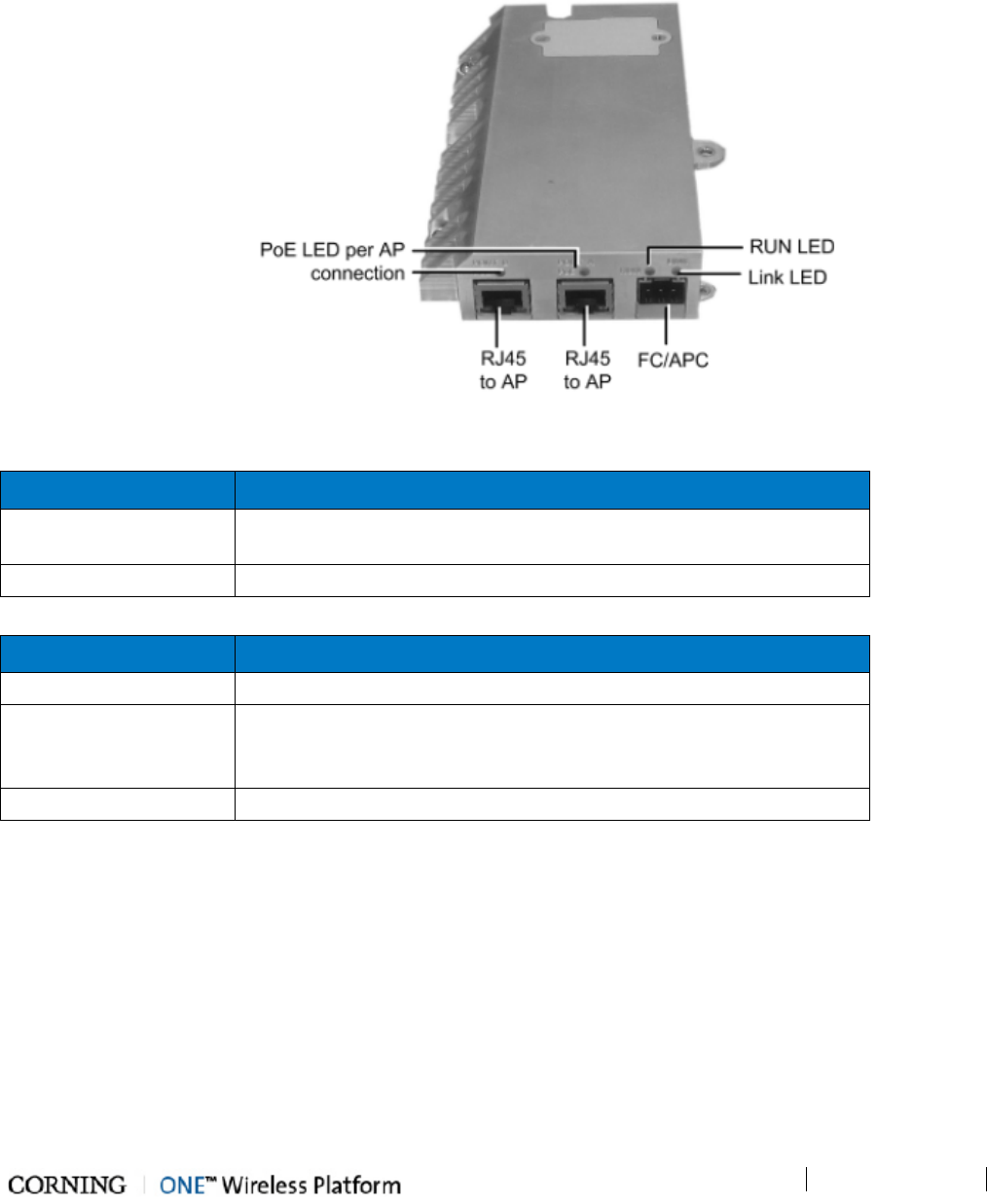
3.3 GEM (Gigabit Ethernet Module)
The GEM converts the received optical signal to two Ethernet digital connections, which are then routed along with PoE to two
remote access points. The GEM module can be installed in the following configurations:
• Installed in RAU - as an optional plug-in module (see RAU (on page 39))
• As a standalone module (GEU-S) - (see section GEU-S Installations (on page 52))
Figure 3-5. GEM Interfaces
The following tables provide descriptions of the ports and LED indicators.
Port Description
PORT A/PORT B [2] RJ45 ports supporting 10/100/1000Base-T copper interface with
PoE+ 802.3at PSE capability for connections to remote access points
FC/APC [1] LC/UPC Fiber optic port
Table 3-2. GEM Port Interfaces
LED Description
PoE (PORT A/PORT B) Indicates power supplied to connected AP
Link
ON - the optical link to/from the connected remote functions within the
specifications in both directions.
Blinking - optical power from remote is lower than required
RUN Steady Green – GEM module SW is up and running
Table 3-3. GEM LED Indicator Descriptions
Unit Descriptions - Digital Path
P/N 709C011801
Page 44
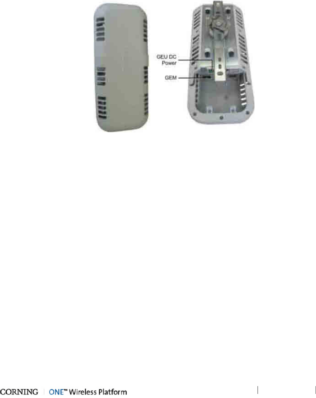
3.4 GEU-S (GEM Standalone)
The GEU-S serves as the GEM docking station, enabling it to function as a standalone unit. The GEU provides the mounting
option and DC power supply for the GEM module. See GEU-S Installations (on page 52) section for details on installation.
Figure 3-6. GEU Enclosure: Top (Left) and Open Underside (Right)

Installation – RF Path Elements
P/N 709C011801
Page 45
4 Ins tallation – R F Path E lements
This chapter describes the installation of the RF path components. It contains only brief descriptions of the approach of each
installation procedure. For step-by-step installation descriptions, refer to the Quick Start Guides provided with the ordered units
and modules, and for specific guidelines on infrastructure planning, design and installation, please consult with a Corning
Product Line Manager or Corning approved Installer.
4.1 RF Headend Installation
The (RF coverage) headend site installation consists of installing the HEU and OIU units.
Note the following information (for both HEU and OIU units):
• The chassis and modules are supplied separately and must be inserted by the user. Only the fan module is factory installed
in the HEU/OIU chassis rear.
• The HEU and OIU units are installed at the IDF (Intermediate Distribution Frame), adjacent (or as close as possible) to each
other to facilitate the connections.
• Hot-swappable modules: RIM (RF Interface Modules) and Power Supply(ies), Fan Modules and RIX/OIX (HEU/OIU
Expander Modules). HCM, ACM modules are not hot-swappable.
• If a redundant power supply is provided, both supplies must be installed, connected to AC power and switched ON.
4.1.1 HEU Installation
Note the following information:
• The RF service interfaces are implemented by service specific RIM/RIM-M modules that are provided separately according to
your order.
• In a Master/Slave configuration, the HEU unit determined as the Slave is managed via the Master unit using an RJ45
connection. Also, the Slave HEU will include an ACM (Auxiliary Control Module) and not an HCM.
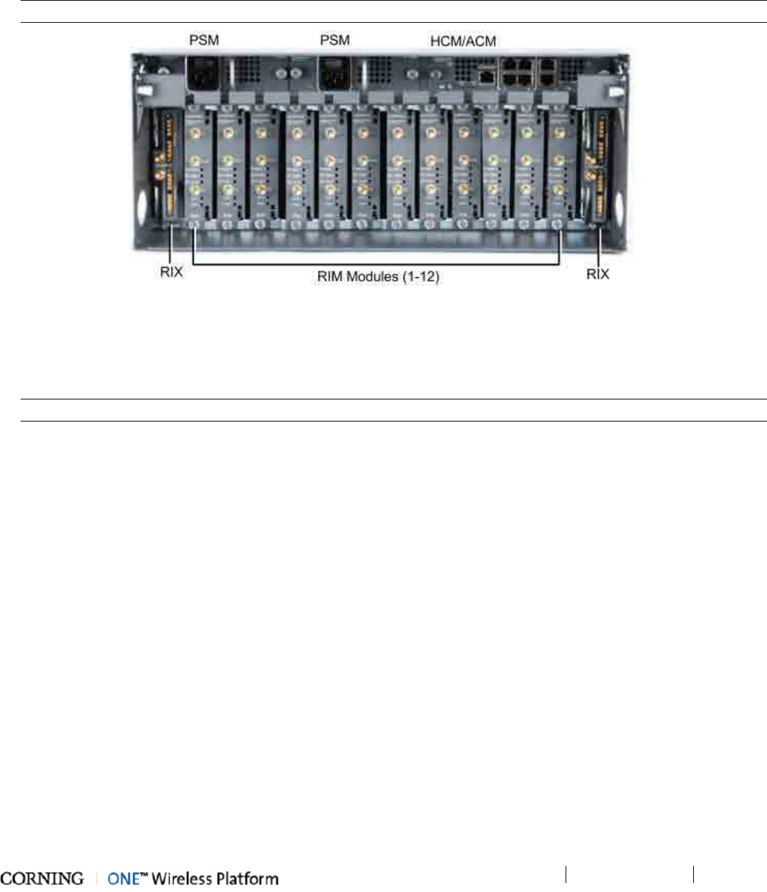
Installation – RF Path Elements
P/N 709C011801
Page 46
To install HEU
1. Mount HEU chassis - mount the (empty) HEU chassis in the 19-in rack.
2. Install modules - install modules (RIM, RIX, PSM and HCM (or ACM for Slaves) into their respective slots (see following
figure).
IMPORTANT! Unoccupied RIX (Expander Module) slots must be terminated with an Expander Termination module.
Figure 4-1. Fully Occupied HEU Chassis
3. Power-On - connect the power cable(s) to the AC outlet(s) and switch On. If two PS modules are installed, both must be
connected.
4. RF connections - connect the RIM/RIM-M QMA (simplex or duplex connections) to the corresponding RF source (e.g.
BTS, BDA).
IMPORTANT! Be sure to terminate any unused QMA connectors with 50 ohm terminators.
5. HEU Management connections:
• Master/Stand-alone HEU - connect HCM LAN port to the corporate LAN
• Slave HEU - connect a Slave ACM RJ45 INTERNAL port (any port) to a Master HCM RJ45 INTERNAL port.
6. HEU to OIU connections:
• RF - connect the HEU RIX to the corresponding OIU OIX port using the expander cable (provided with the OIU).
• Management - connect an HEU HCM/ACM INTERNAL port to an OIU ACM INTERNAL port.
7. Verify HEU normal operation:
• Check LEDs on the HCM/ACM. See section HCM (Headend Control Module) (on page 30)
• Check LEDs on each RIM/RIM-M module. See RIM (RF Interface Module) (on page 31).
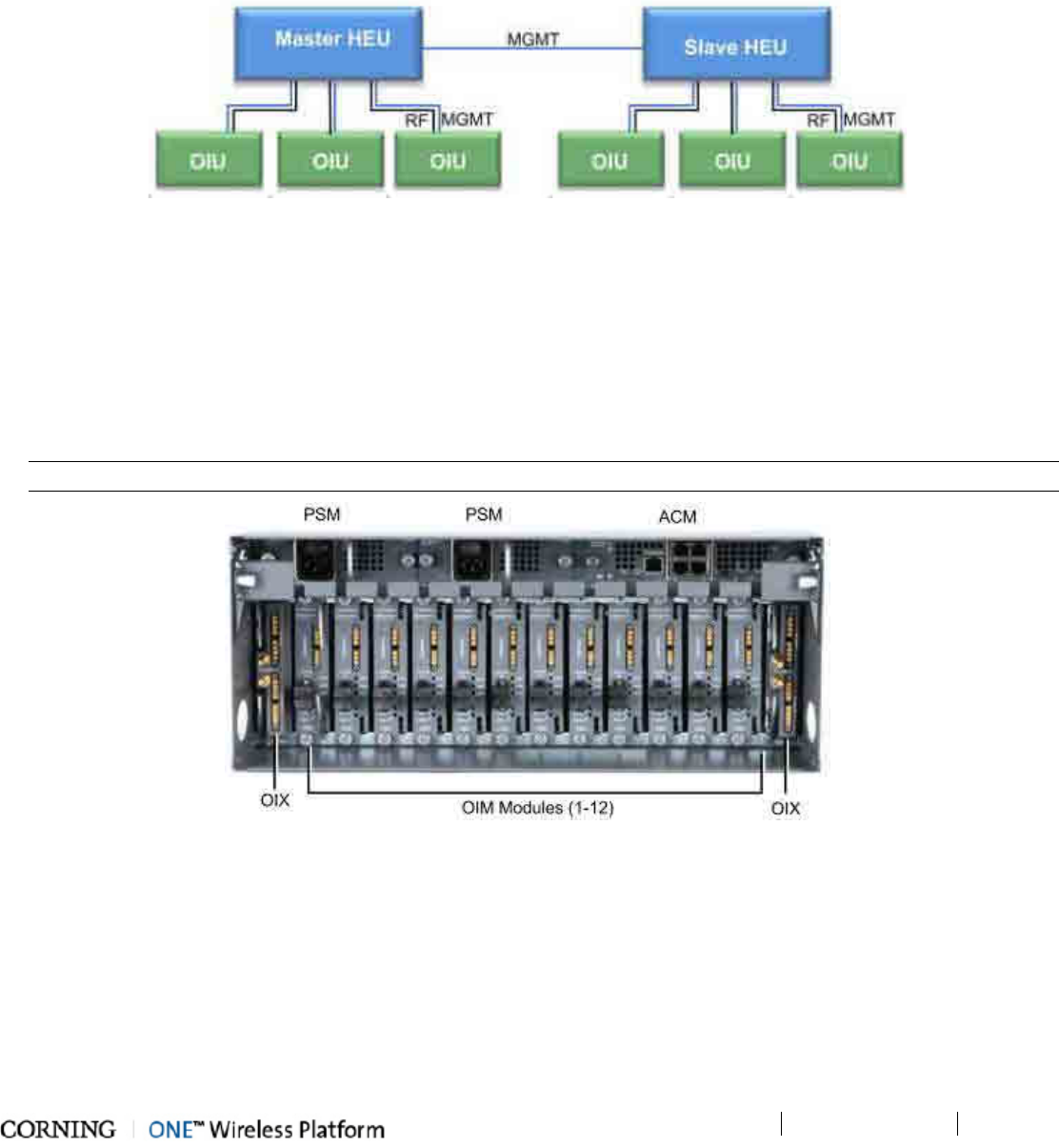
Installation – RF Path Elements
P/N 709C011801
Page 47
4.1.2 Example of HEU Master-Slave Installation
A Master-Slave HEU configuration enables single source management of several HEUs (and hosted elements) from a single HCM.
The following figure provides an example of the connections between a Master and one Slave.
Each OIU is connected to its host HEU through two connections: MGMT (ETH to INTERNAL port) and RF (RIX/OIX ports). For
standalone configurations, up to four OIU can be connected to an HEU; for Master/Slave configurations, up to three OIU can be
connected to an HEU (since one of the MGMT ports is used by the Master/Slave connections.)
Figure 4-2. Example of Connections for Master-Slave Configurations
4.1.3 OIU Installation
Note that each OIU interfaces to one HEU; each OIM interfaces to up to three RAU units (located at the remote end) via an MTP
connection.
To install OIU
1. Mount OIU - mount the (empty) OIU chassis in the 19-in rack.
2. Install modules - install modules (OIM, OIX, PSM and ACM) into their respective slots. See following figure.
IMPORTANT! Unoccupied OIX (Expander Module) slots must be terminated with an Expander Termination module.
Figure 4-3. Fully Occupied OIU Chassis
3. Power-On - connect the Power Supply Module(s) to the AC outlet(s) and switch On. If two modules are installed, both
must be connected.
4. HEU connections:
o Connect the OIU OIX to the corresponding HEU RIX port using the provided Expander cable.
o Connect an ACM INTERNAL port to an HEU HCM INTERNAL port with an Ethernet cable.
5. OIM connections - connect the optic modules to the designated optic ports in the fiber-optic patch panel.
6. Verify OIU normal operation - via the LED indicators on the ACM and OIM modules. See sections ACM (Auxiliary
Control Module) (on page 34) and OIM (Optical Interface Module) (on page 35) respectively for description of
LEDs.
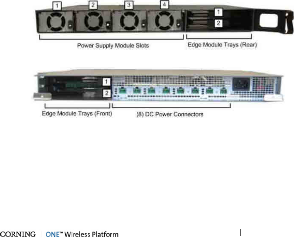
Installation – RF Path Elements
P/N 709C011801
Page 48
4.2 RF Remote-End Installation
The remote end site (RF coverage) installation consists of installing the ICU (on page 48) unit and RAU (on page 48) module(s).
4.2.1 ICU Installation
4.2.1.1 General Information
• The ICU is a passive unit installed at the floor level and provides the power and fiber interfaces to the RAU units (and to the
GEU for the digital path).
• Connections between the ICU and the RAU units are performed via Corning composite cables (ordered separately) consisting
of:
• 2 DC wires
• 3 LC/APC pairs
• The chassis and modules are supplied separately and must be inserted by the user.
• All ICU modules (i.e. PS and Edge) are hot-swappable
• Each ICU chassis hosts up to four Power Supply modules and up to two Edge modules
To install the ICU
1. Install modules - install Power Supply (from rear) and Edge modules (from rear/front).
Figure 4-4. Location of Modules in ICU
2. Mount ICU - mount the ICU in a 19-in rack or on wall.
3. OIU connections - connect the optic fibers from the patch panel on the floor level leading from the OIU to Edge module
MTP connector (accessed from ICU rear).
4. RAU connections – using the Corning composite cable, connect the DC wiring and LC/APC fibers to the corresponding
ICU Edge module and DC power connectors and to the relevant RAU(s).
5. Power up – connect the ICU to the AC power outlet using the provided 110-240V AC power cable.
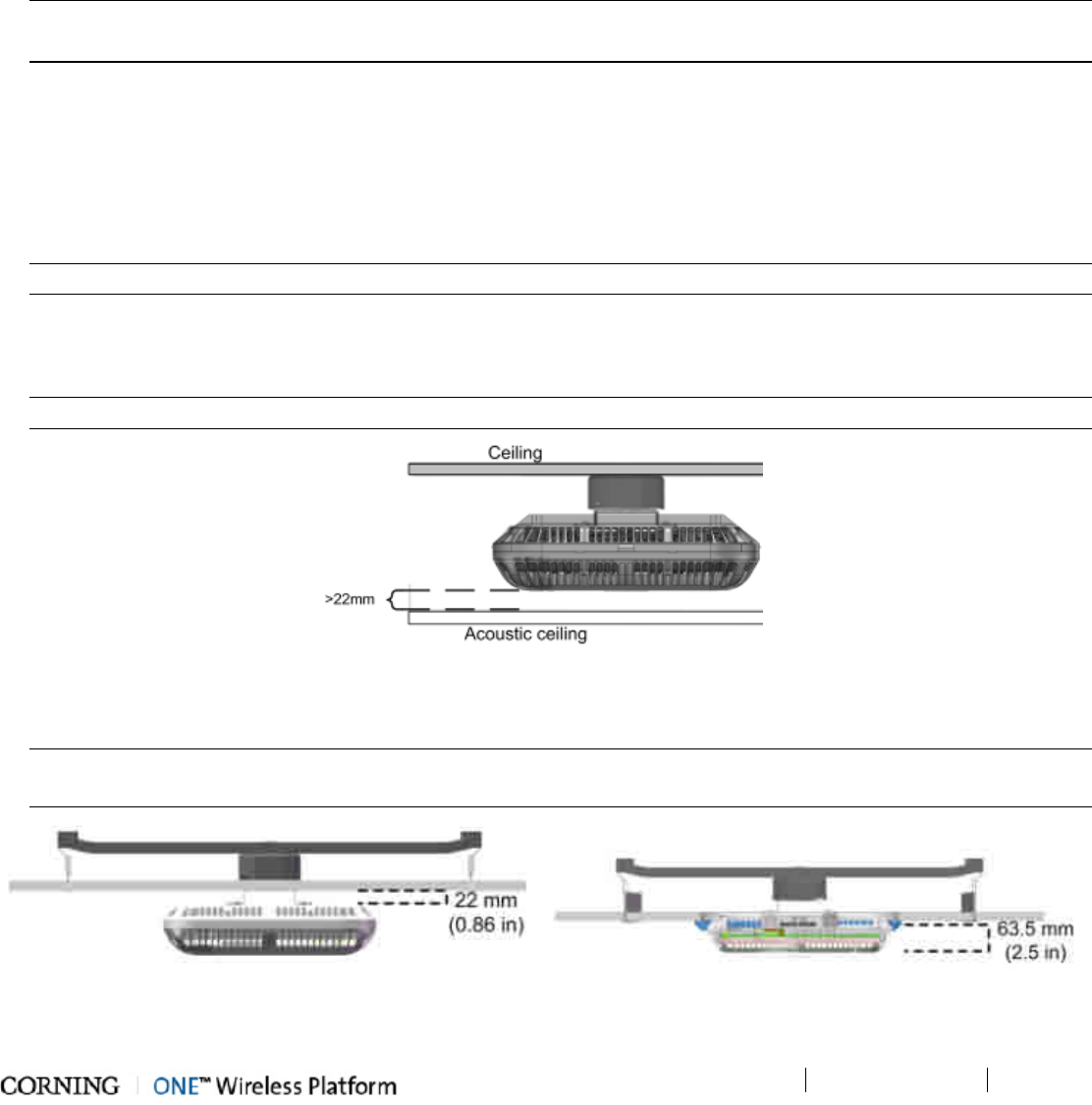
Installation – RF Path Elements
P/N 709C011801
Page 49
4.2.2 RAU Installation
4.2.2.1 General Information
• The RAU modules are deployed on the floor level and interface to the RF antennas.
• The RAU can be provided in a number of configurations:
• RAU (without RxU and GEM)
• RAU + RxU
• RAU + GEM
• RAU + RxU + GEM
NOTE: Existing RAU units can be upgraded with RxU and/or GEM modules – relevant Quick Start Guide with installation
instructions are provided with ordered units.
• The RAU supports various mounting installation options: wall/ceiling/acoustic ceiling
If the RAU is installed below or mid-mount an acoustic ceiling, a support bar (T-Bar) is required (not included).
Acoustical Ceiling grid work is not designed to support the weight of the enclosure.
• RAU optic fiber connections and DC power are provided via a Corning Composite cable (ordered separately).
To install the RAU
1. Locate fiber and DC connections cables - Corning Composite cable wiring leading from ICU.
NOTE: RAU units that include GEM modules, require additional DC wire for Secondary Power connection and Ethernet.
2. Mount the installation bracket according to one of the following installation options:
• Wall-mount: mount bracket on wall
• Concrete/Above Acoustic Ceiling: route connections cables through bracket and install bracket on ceiling
NOTE: When installing above acoustic ceiling, allow for at least 22 mm (0.86 in) above the acoustic ceiling for ventilation.
Figure 4-5. RAU Installed Above Acoustic Ceiling
3. Below/Mid-Mount Acoustic ceiling: Cut-out opening in acoustic tile (mid-mount only), install T-Bar in ceiling above, route
connections and install bracket on T-Bar.
NOTE: For Below ceiling installations - 22 mm (0.86 in) between ceiling tile and RAU; For Mid-Mount installations - 63.5 mm
(2.5 in) between ceiling and lowest part of RAU.
Figure 4-6. Below Ceiling Installation (left figure) and Mid-Mount Ceiling Installation (right image)
4. Connect cables:
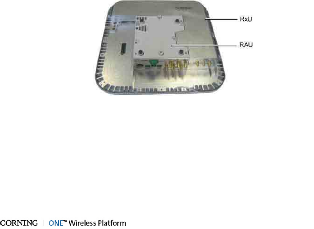
Installation – RF Path Elements
P/N 709C011801
Page 50
• DC connection:
o RAU (without GEM) - MAIN POWER connection
o RAU + GEM - MAIN POWER + SECONDARY POWER connections
• Fiber optic connection
• External antenna (for above ceiling installations)
• (Optional) RF filter connections (check with site planner) - for RAU and RxU (if exists)
• GEM module connections (for RAU+GEM) - Ethernet and 3PE connections
5. Verify normal operation - via front cover LEDs:
• RUN - Blinking green
• LINK – Steady green
• POWER – Steady green
4.2.3 RxU Installation
4.2.3.1 General Information
• The RxU expands the RAU band support to additional 2 MIMO bands.
• The RxU can either be pre-installed in the RAU module (according to order) or easily added at a later stage when required.
• The installation of the RxU module in the RAU unit does not require disconnecting cables or power.
To assemble RxU on to RAU
1. Dismount RAU from mounting bracket and remove RAU enclosure cover.
2. Assemble RxU - fit RxU into dedicated location (on the right) and replace cover (except for front panel).
Figure 4-7. RAU and RxU Module Assembly
3. (If required by site planner) - connect the filter to the RF filter connectors on the RxU.
4. Verify normal operation – via front enclosure cover:
• RUN – Blinking Green
• POWER – Steady Green
• LINK – Steady Green
5. Re-mount RAU onto mounting bracket.
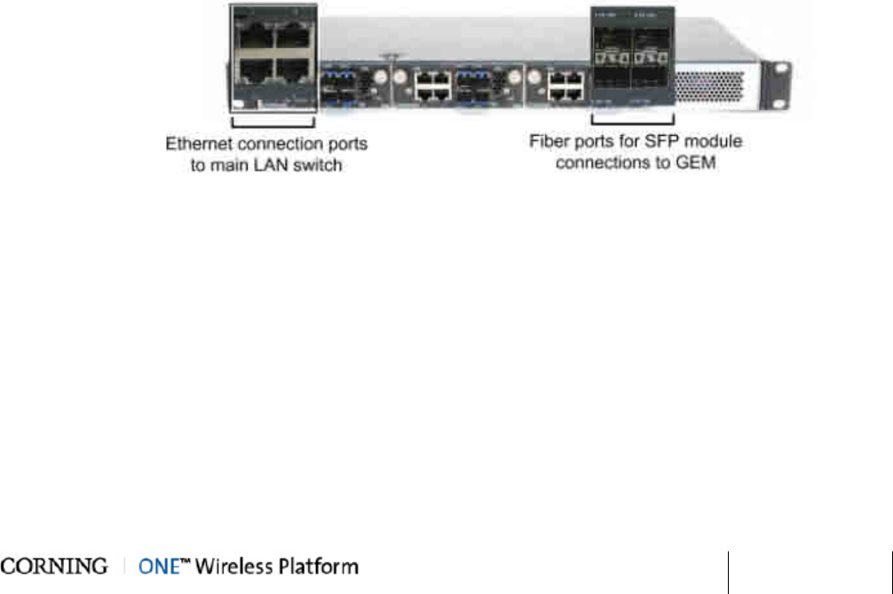
Installation – Digital Coverage
Elements
P/N 709C011801 Page 51
5 Ins tallation – Digital Coverage Elements
This chapter describes the installation of the Digital Coverage components. It contains only brief descriptions of the approach of
each installation procedure. For step-by-step installation descriptions refer to the Quick Start Guides provided with the ordered
units, and for specific guidelines on infrastructure planning, design and installation, please consult with a Corning Product Line
Manager or Corning approved Installer. All these elements are installed at the remote end.
5.1 CEU Installation
General Information
• The CEU interfaces to the main Ethernet switch and to the remote Gigabit Ethernet Modules (GEM).
• The CEU is rack mounted or wall mounted at the IDF (Intermediate Distribution Frame).
• The CEU can host up to 3 CEM (Centralized Ethernet Modules), which are not included in the CEU package.
• The CEM Tx/Rx Ethernet fiber ports, used for interfacing to the GEM modules, require SFP modules (included) and LC-UPC
to LC-APC adapter.
To install the CEU
1. Install CEM modules in the CEU chassis.
2. Mount CEU chassis - rack mount or wall mount
3. Connect CEM to main LAN (Ethernet switch).
4. Con
5. nect fiber – fiber connections between CEU SFP modules and GEM modules.
Figure 5-1. CEU Ethernet and Fiber Ports
6. Power up – using 110-240VAC power cable.
7. Verify normal operation - via F/O, ETH and PWR status LEDs.
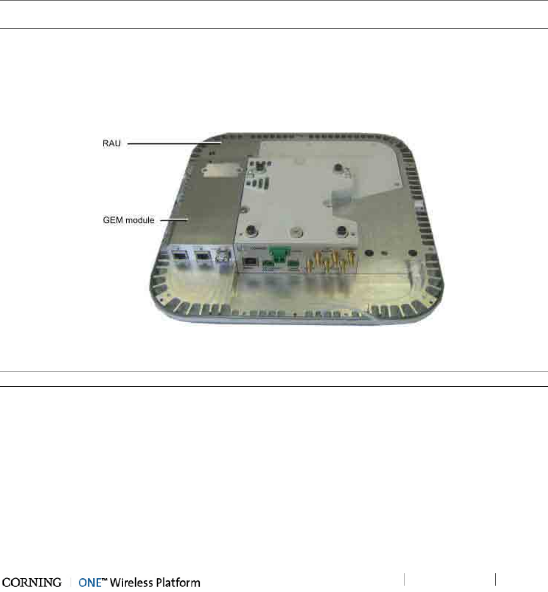
Installation – Digital Coverage Elements
P/N 709C011801
Page 52
5.2 GEM
The GEM unit is either pre-installed in the RAU unit or in the Gigabit Ethernet Unit (GEU):
• RAU + GEM configurations - only require GEM module connections to Ethernet and 3rd party Access Points (DC power
provided via RAU Secondary Power connection)
• GEU (includes GEM) configurations - standalone installation which requires mounting the GEU and performing the power and
Ethernet connections.
NOTE: GEM modules can also be installed in existing RAU enclosures for expanded data coverage. Detailed instructions on how
to install the GEM module in an RAU enclosure are provided in the Quick Start Guide provided with the module.
5.2.1 GEM Installations with RAU Module
To mount the GEM on to the RAU module
1. Dismount the RAU (if already installed).
2. Plug in the GEM module into the dedicated location (left side of the RAU module) and replace cover (except for front
panel).
Figure 5-2. Inserting GEM in the RAU Enclosure
3. Remount the RAU.
NOTE: Refer to GEM QSG for a more detailed procedure.
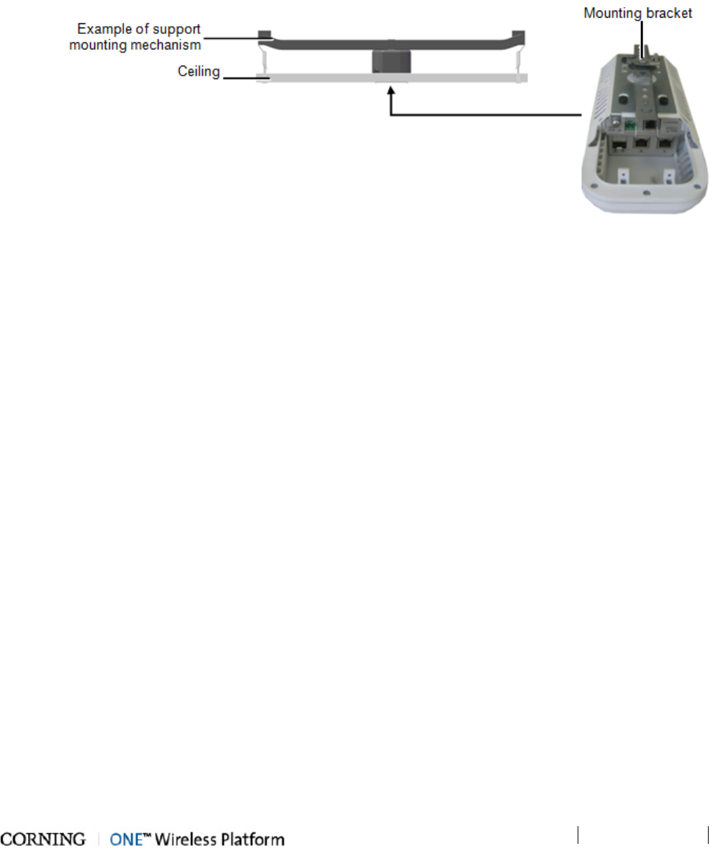
Installation – Digital Coverage Elements
P/N 709C011801
Page 53
5.2.2 GEU-S Installations
To install the GEU-S assembly
1. Locate the Ethernet and DC power wiring cables.
2. Hold the GEU near the mounting mechanism (not provided) and route the ETH and F/O cables through the mounting
bracket. See QSG for details.
3. Mount the GEM with GEU enclosure onto a mounting mechanism.
Figure 5-3. Overview of GEU-S Installation
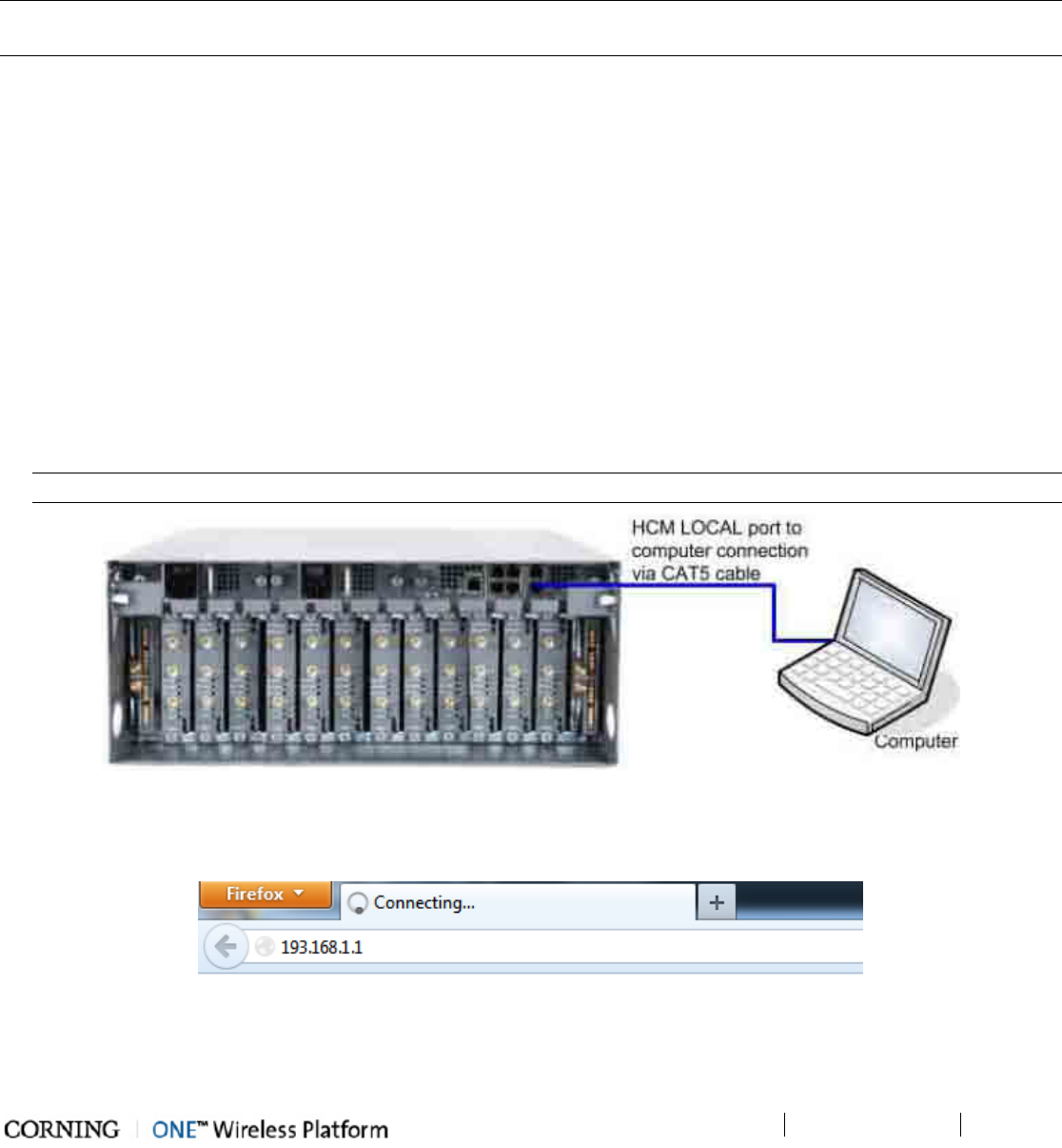
Commissioning the System
P/N 709C011801
Page 55
6 Commissioning the System
After physically installing all of the headend and remote-end elements, the initial setup procedure can be performed and the
system can be commissioned either via a local or remote connection.
NOTE: When unconfigured elements are detected the following message appears in the Config window of the Web Management
GUI: "New uncommissioned units found, please run setup".
The initial setup procedure consists of the following steps:
• Opening a local Web Management session (on page 55) using the default IP address assigned to the HEU
• Configuring the LAN and LOCAL Port Network Settings (on page 56) for remote or local management
• Performing required pre-setup procedures
• Running the Setup procedure (on page 62)
• Performing the System Adjustment Procedure (on page 73)
6.1 Opening a Local Session
To open a local Web Management session
1. Verify that your computer Local Area Connection (Properties / TCP/IP / Properties) is set to obtain the "DNS Server Address
Automatically".
2. Connect a computer (i.e. laptop) directly to the HEU HCM LOCAL port via the supplied RJ-45 Ethernet cable (P/N
705900003) as shown in the following figure.
WARNING! DO NOT connect the HCM LOCAL port to a network as its DHCP server can disrupt LAN IP addressing.
Figure 6-1. Local Connection Between (HEU) HCM and Computer
3. Assign your computer an IP address to operate in the same subnet as the HCM (default HCM IP address = 193.168.1.1).
4. Open the Web browser and enter the HCM IP Address (default HCM IP address = 193.168.1.1).
Figure 6-2. Entering HCM IP Address into browser
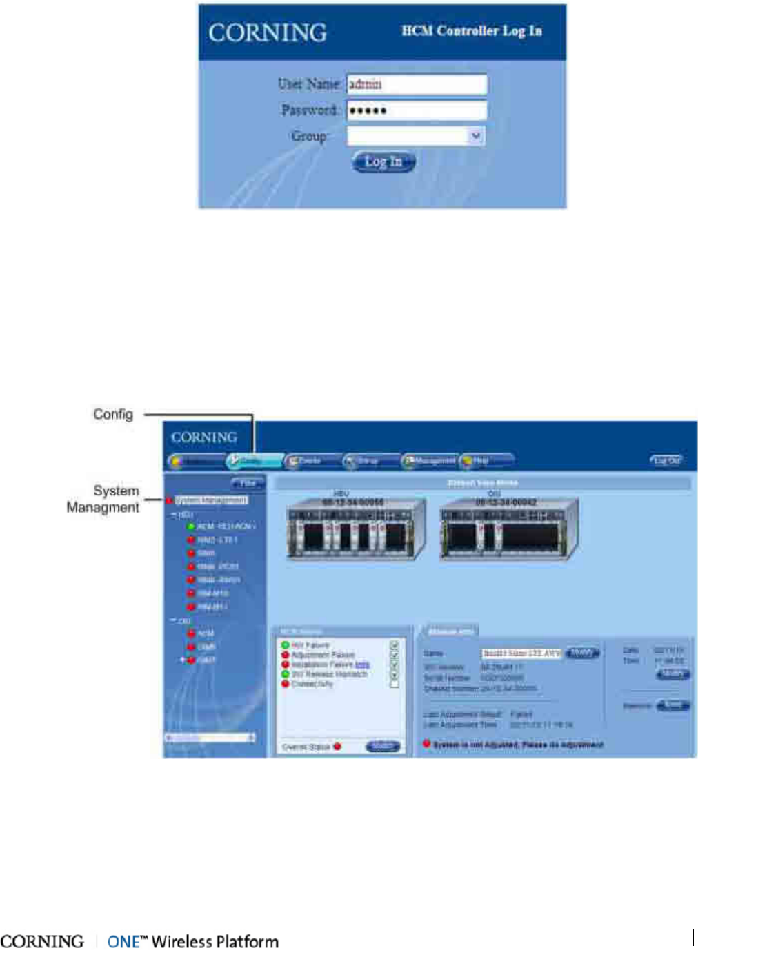
Commissioning the System
P/N 709C011801
Page 56
The HCM Controller Log In dialog appears.
Figure 6-3. Log In Dialog
5. First time access authentication:
• User Name = admin
• Password = default provided with your system - to receive from CMA
• Group = leave blank
NOTE: For security, it is highly recommended to immediately change the password (Management tab, Security option) and
login again using the new password.
6. Click the Log In button. The System Management (HCM) Module Info tab appears.
Figure 6-4. System Management Module Info tab
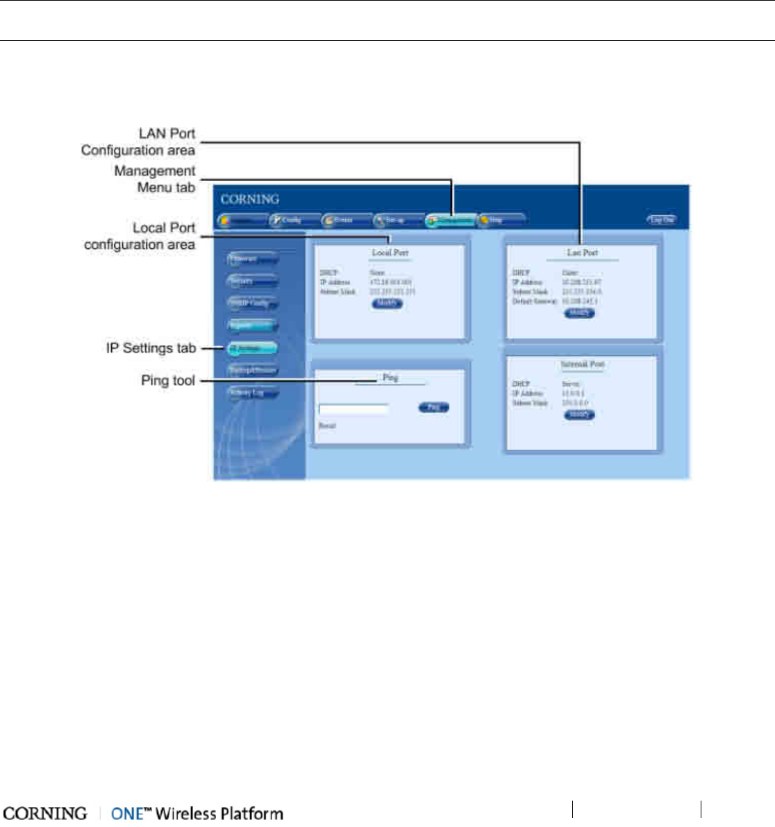
Commissioning the System
P/N 709C011801
Page 57
6.2 Configuring HCM Network Settings for Local and Remote
Management
There are two options for configuring the HCM network parameters for remote management across the customer LAN:
• HCM LAN port – assigning the HCM LAN port a static or dynamic IP address
• HCM LOCAL port – assigning a static IP address and connecting to the customer’s LAN for remote management; however,
for troubleshooting and service purposes, a local connection is recommended.
NOTE: The IP address configuration options are provided on the Management, IP Settings pane. The same pane also provides
a Ping tool used for verifying access to other IP hosts (see section Ping Tool - Verifying IP Host Access (on page 59)).
To Configure HCM for Remote/Local Management
1. Open a Web session
2. Select the Management tab and then click IP Settings on the side bar menu.
Figure 6-5. Management-IP Settings Tab
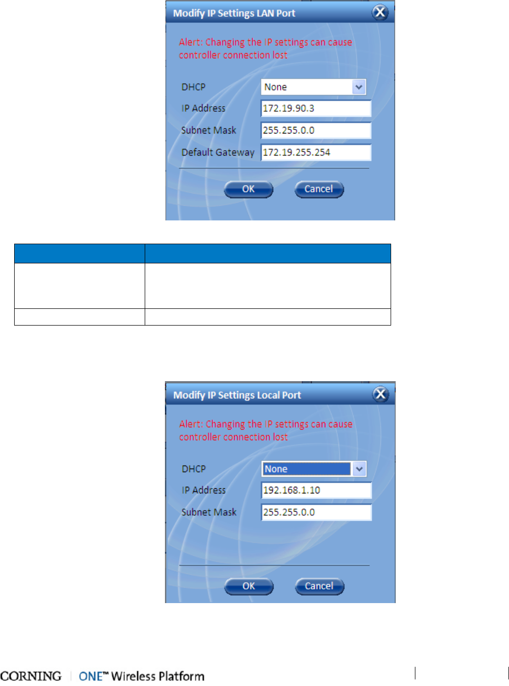
Commissioning the System
P/N 709C011801
Page 58
3. To change the LAN Port network settings, click the Modify button in the LAN Port Configuration Area. The following
dialog appears.
Figure 6-6. IP Settings LAN Port Modify Dialog
To Define… Do This…
Static IP Address
Set DHCP as None.
Enter the IP Address, Subnet and Gateway.
Click OK.
Dynamic IP Address Set DHCP as Client and click OK.
Table 6-1. LAN Port IP Settings
4. To change the LOCAL Port network settings, click the Modify button in the LOCAL Port Configuration Area. The
following dialog appears.
Figure 6-7. IP Settings Local Port Modify Dialog
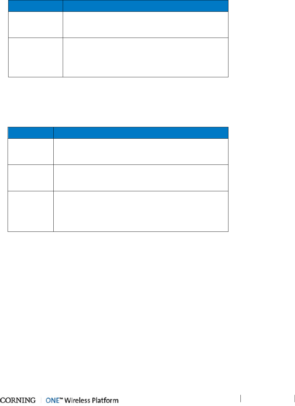
Commissioning the System
P/N 709C011801
Page 59
To Define… Do This…
Static IP Address
Set DHCP as None.
Enter the IP Address and Subnet.
Click OK.
DHCP Server
Set DHCP as Server and click OK.
WARNING!!! If LOCAL port is set as DHCP Server, DO NOT
connect a network device, as its DHCP server can disrupt LAN
IP addressing. Only use this setting if using the port for direct
connection to a client device (i.e. PC).
Table 6-2. Local Port IP Settings
6.2.1 Default Network Parameters
The following table describes the default settings for each of the Network Ethernet ports located on the Headend Control Module
(HCM).
Port Name Configuration
LOCAL
DHCP: off
IP: 193.168.1.1
Subnet Mask: 255.255.0.0
LAN
DHCP: Client, or Static IP (default)
IP: 192.168.1.1
Subnet Mask: 255.255.0.0
INTERNAL
DHCP: server on (this local port is set by default set to act as a
DHCP Server and provide an IP address to the connected
computer so no configuration of the computer is required)
IP: 11.0.0.1
Subnet Mask: 255.0.0.0
Table 6-3. Default network parameters
D
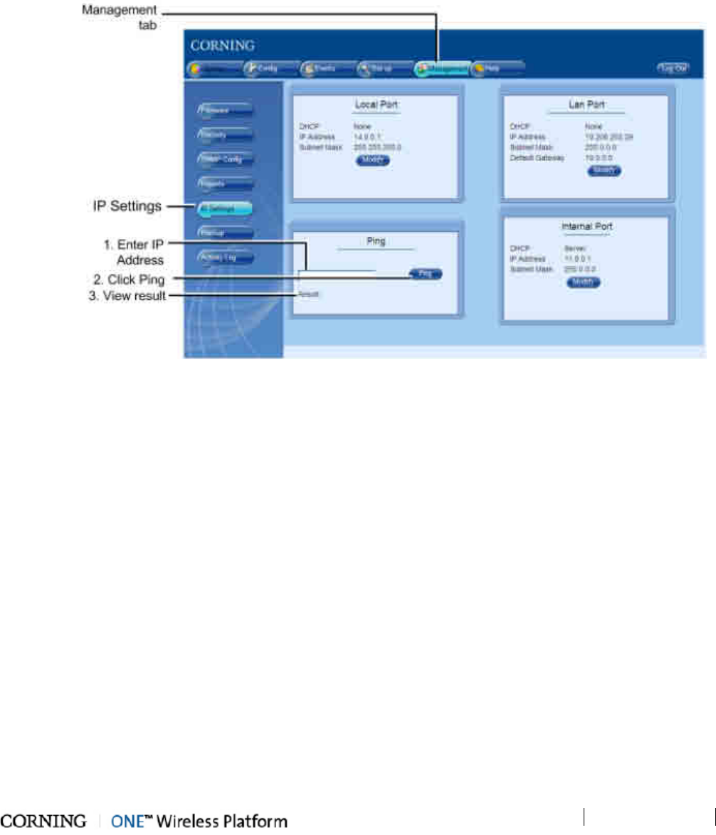
Commissioning the System
P/N 709C011801
Page 60
6.2.2 Ping Tool - Verifying IP Host Access
A Ping Tool option is provided in the IP Settings pane. Use this tool to verify access to IP hosts (rather than opening another
application).
To use the Ping tool
1. Click the Management tab and then the IP Settings menu option.
2. In the Ping work area, enter the IP address and the click the Ping button.
3. The validity/invalidity result of the IP address will appear in the Result line.
Figure 6-8. Management-IP Settings-Ping Tool Option
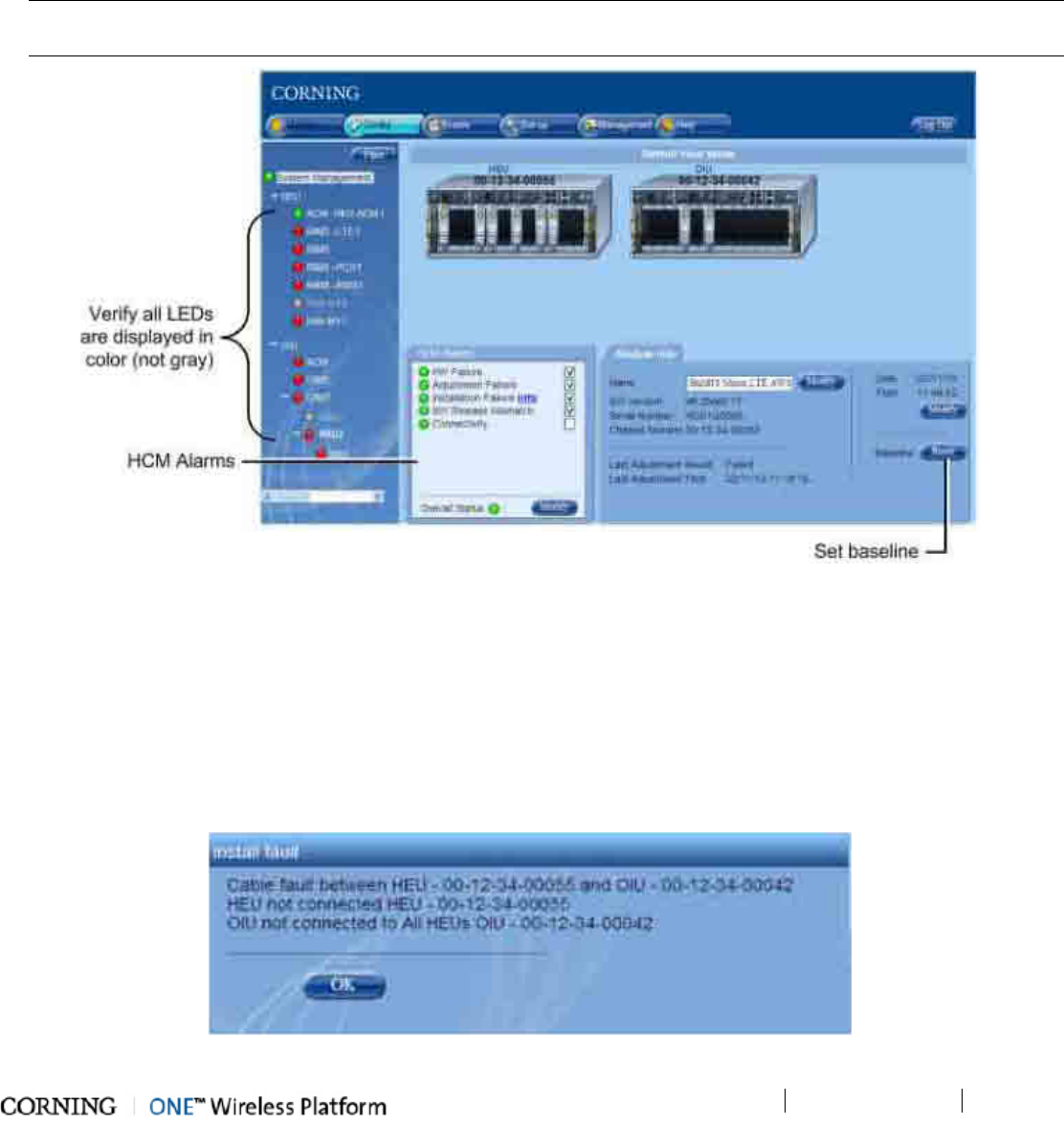
Commissioning the System
P/N 709C011801
Page 61
6.3 Required Pre-Setup Procedures
Perform the pre-setup procedures as follows:
1. Verify that all of the installed devices have been automatically detected:
• Click the Config tab. In the Topology Tree.
• Verify that the LEDs adjacent to all of the Topology Tree items (ACM, RIMs, OIMs, RAUs, etc.) are colored in any other
color but gray.
• If an item is gray, verify the physical connections.
NOTE: You may use the Baseline reset button to set all of the devices currently displayed in the Network Topology pane as
a reference and continue displaying them (in gray) even if communication is lost with a device.
Figure 6-9. Verifying detected Device in Network Topology
Verify all devices are displayed in the tree
2. In the HCM alarms tab, verify that all system alarms are green:
• In the Topology Tree, click System Management.
• In the HCM Alarms tab, verify all alarms are green.
• If any of the alarms are not green, refer to HCM Alarms (on page 126).
• If the Installation Failure alarm is red, click on the Info hyperlink. The Installation Failure dialog will appear, listing the
detected faulty connections.
Figure 6-10. Install Fault Details Dialog
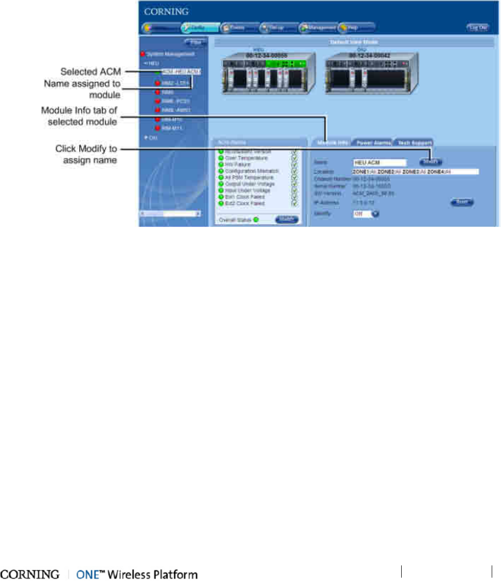
Commissioning the System
P/N 709C011801
Page 62
3. Verify the correct system time and date are set (used for Events time stamp):
• In the Topology Tree, click System Management.
• In the Module Info tab, Date and Time area, click Modify and set the time and date.
4. (Optional) - you may assign a recognizable name to each of the modules (e.g. ACM, RIM, OIM, etc.) as follows:
• Click on the module item in the topology tree. A dedicated Module Info tab is displayed for each module.
• Click on the (Name) Modify button and enter the name. The assigned name will appear in the network topology
adjacent to the module item.
Figure 6-11. Assigning Module Name
5. Define User Groups (on page 107) (indicating carriers) to which the HEU RIM modules will be assigned during the
setup procedure.
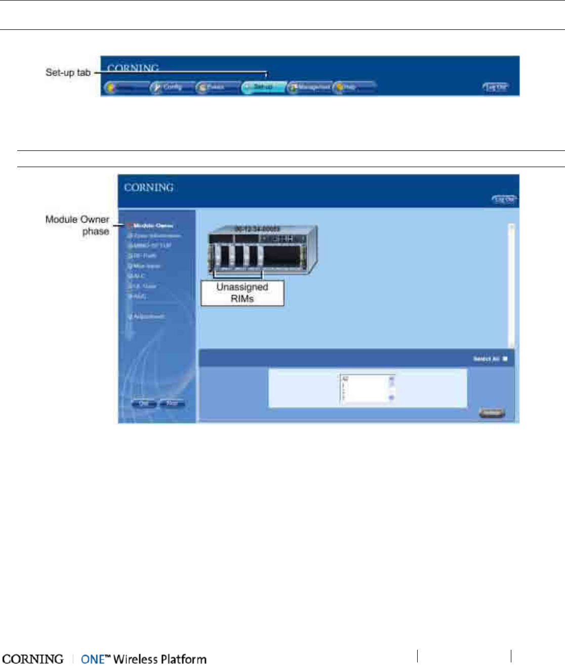
Commissioning the System
P/N 709C011801
Page 63
6.4 Running the Setup Procedure
To perform the setup procedure
NOTE: Make sure that you have performed the required pre-setup procedures (see section Required Pre-Setup Procedures)
before running the Setup tool.
1. Click on the main menu Set-up tab.
Figure 6-12. Setup Tab in Main Menu
The Module Owner screen appears (first phase) and the HEU is displayed in the device view area. The unconfigured and
un-assigned RIM modules appear gray.
NOTE: The RIM information can be viewed by placing the pointer on the RIM icon device.
Figure 6-13. Module Owner Screen – Before Group Assignment
2. Click on the RIMs to be assigned to a group (appear green upon selection), select the group to which the RIMs are to
be assigned and then click Submit.
• Repeat for all RIMs until are modules are assigned to a group.
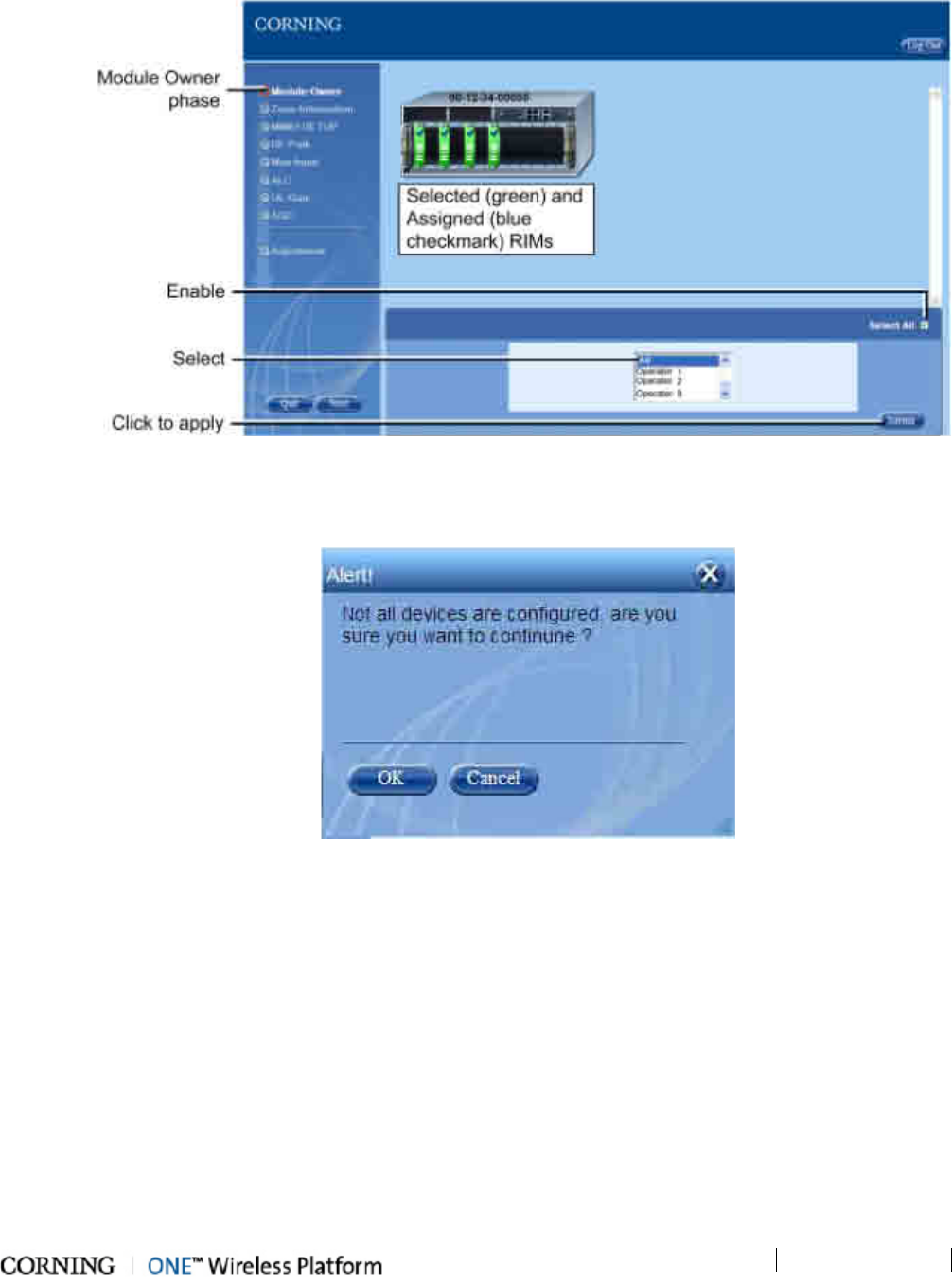
Commissioning the System
P/N 709C011801
Page 64
• If all of the RIM modules are to be accessible to all groups, enable the Select All checkbox and then select All from the
list of groups.
Figure 6-14. Assigned RIM Modules
• The selected and assigned RIM modules appear in green with a blue checkmark.
• If not all of the RIM modules are assigned to a group, the following message appears:
Figure 6-15. Unassigned RIM Module Alert Message
• Click OK to continue or Cancel to assign the remaining RIM modules.
3. Click Next to continue to the Zone Information phase. The Zone Information screens appears with the list of all of the
detected system modules (displayed according to type - e.g. RIM, OIM, etc. and serial number).
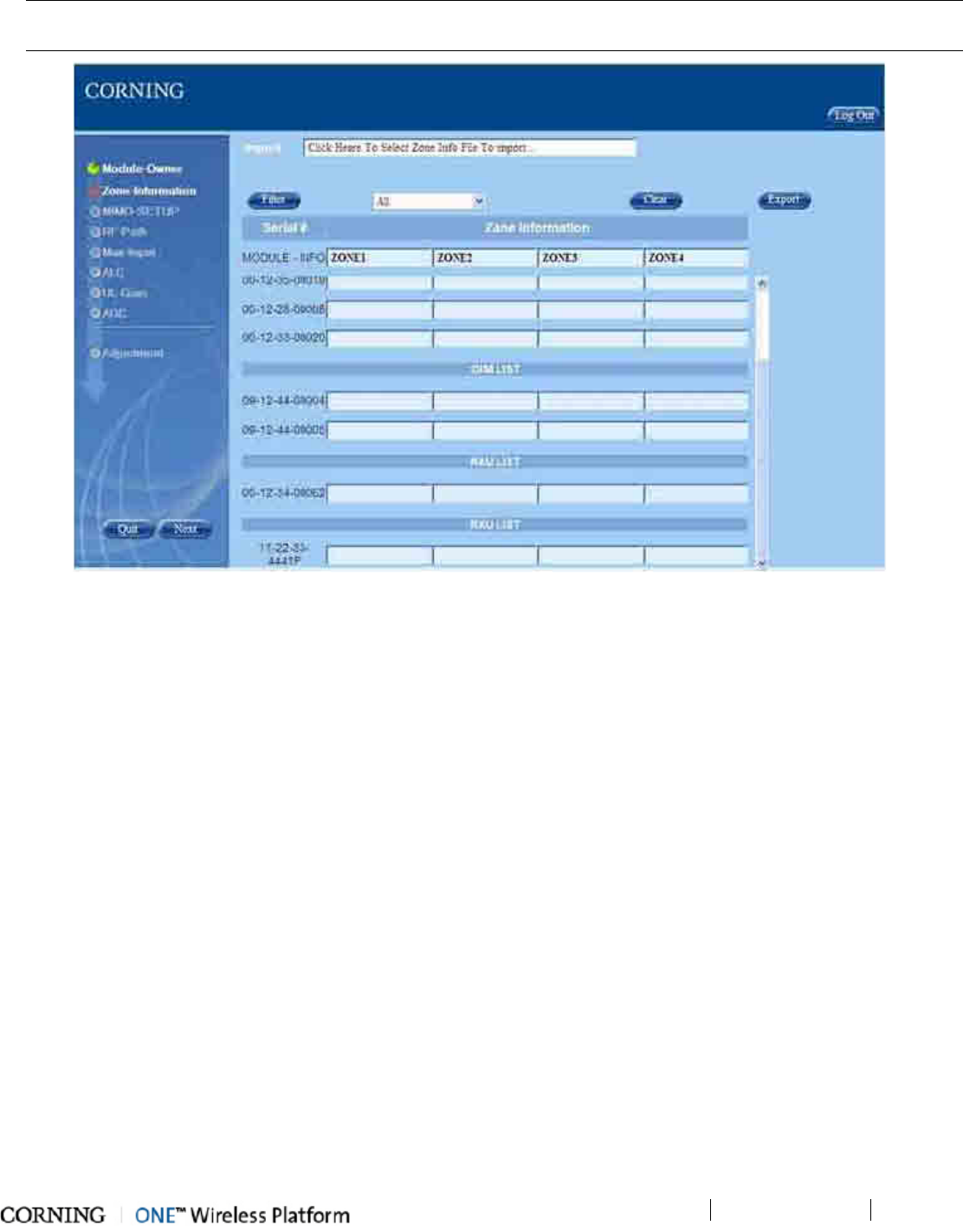
Commissioning the System
P/N 709C011801
Page 65
NOTE: The displayed modules can be filtered according to module type by selecting the module type from the drop-down list
and clicking the Filter button.
Figure 6-16. Zone-Information Screen
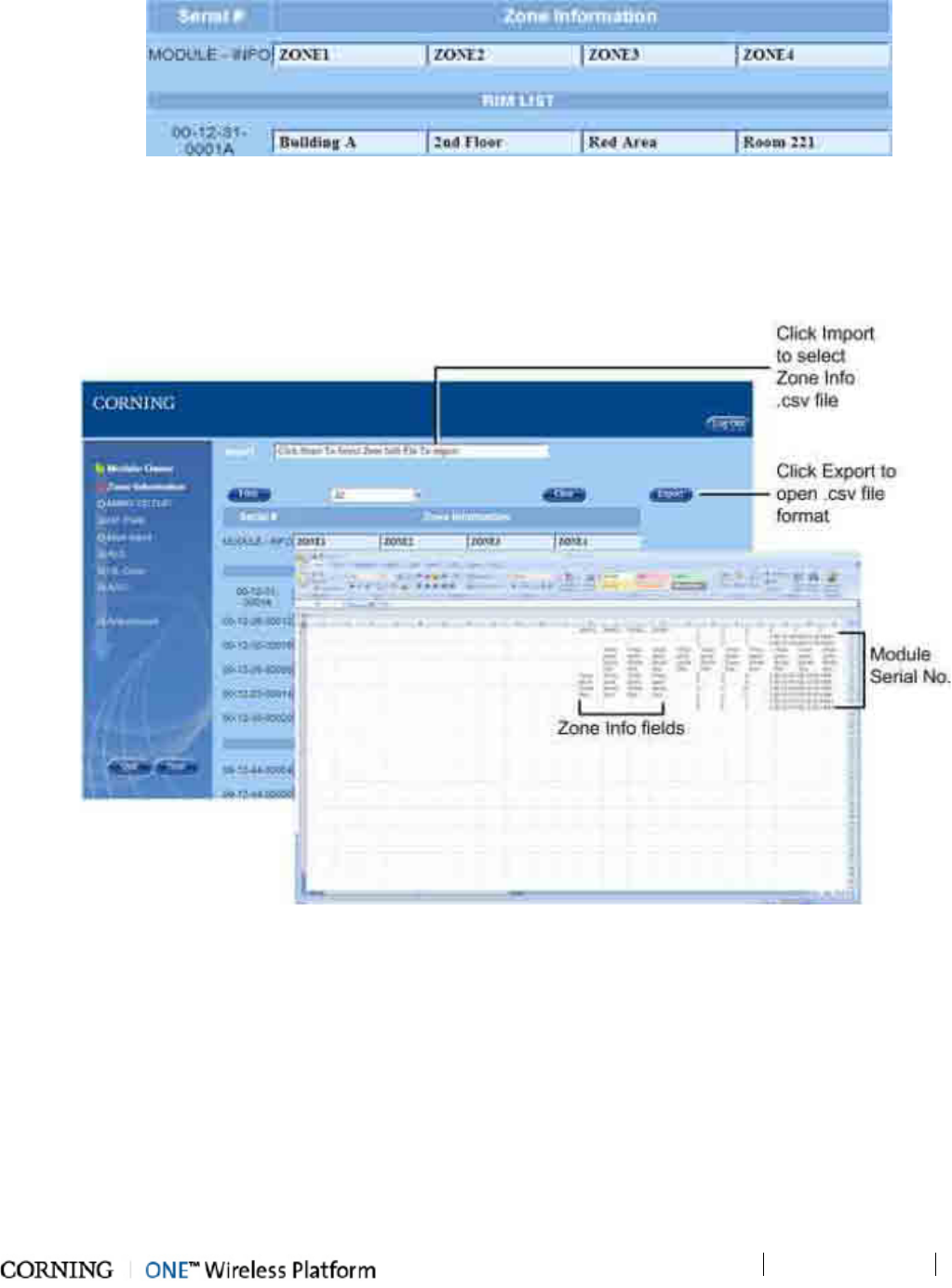
Commissioning the System
P/N 709C011801
Page 66
4. Enter the location description of all of the modules in the ZONE1-ZONE4 fields. Refer to following figure for example.
Figure 6-17. Entering Zone Information
There are two options for entering the zone info:
• Entering the zone information description directly in the ZONE1-ZONE4 fields (as shown in figure above)
• Clicking the Export button to access the Zone Info file (.csv) format. The Zone Info file appears with the list of all
detected modules:
Figure 6-18. Example of Zone Information .CSV File
o Enter the module location information in the ZONE1 - ZONE4 fields of the .csv file and save the file on a location in
your computer.
o In the Import field, click on the "Click Here To Select Zone Info File To import..." text to import the .csv file previously
saved. The download procedure can take up to 5 min.
o A Download Is Completed message will appear upon completing the import process.
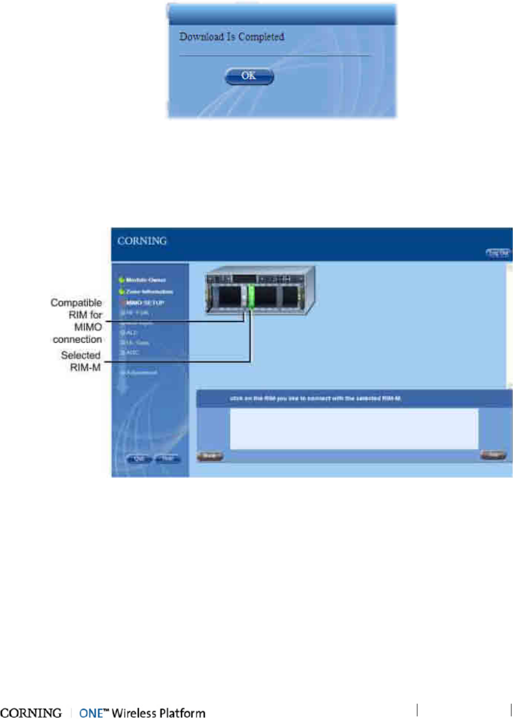
Commissioning the System
P/N 709C011801
Page 67
Figure 6-19. Download Complete Message
The Zone Info is displayed in the Zone Information screen in the corresponding fields and in the (Config) Module Info
tabs of each module.
5. Click Next to continue to the MIMO SETUP screen.
6. To configure modules for MIMO path:
o Select a RIM-M and the available RIM module(s) is indicated.
Figure 6-20. MIMO Setup Phase
o Click on the RIM module to be connected to the RIM-M, so that both appear in green.
o Click on the Join button to connect the selected pair.
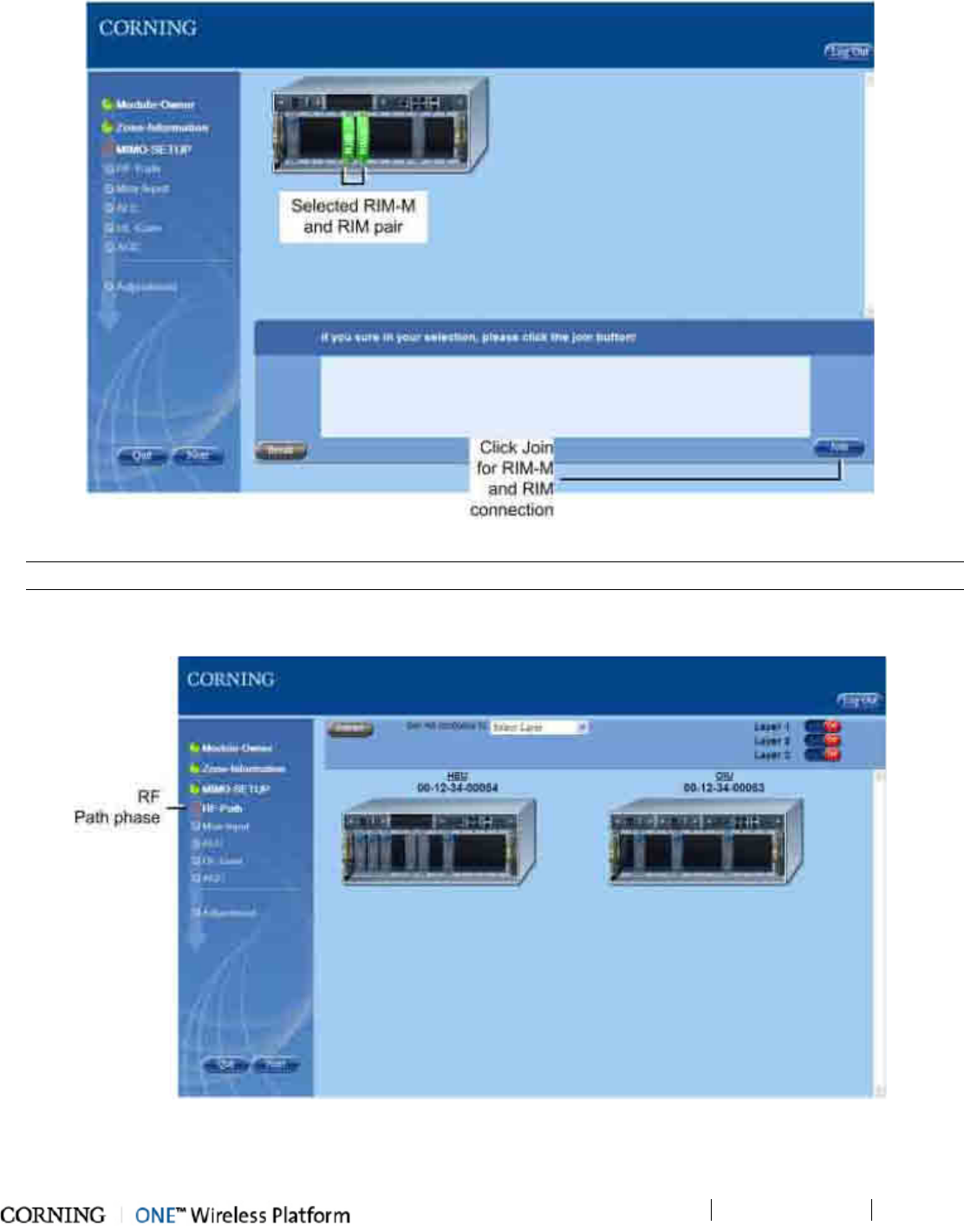
Commissioning the System
P/N 709C011801
Page 68
Figure 6-21. Connecting RIM and RIM-M Modules
NOTE: Each RIM-M can only be connected to one RIM. Use the Break button to disconnect a pair of RIM-M and RIM modules.
o Click OK if Progress Result is successful and repeat for additional MIMO pairs.
7. Click Next to continue to the RF Path phase. The RF Path screen appears.
Figure 6-22. RF Path Screen - Default Display upon Initial Setup
8. Configure the RF paths between the headend and the remote-end units.
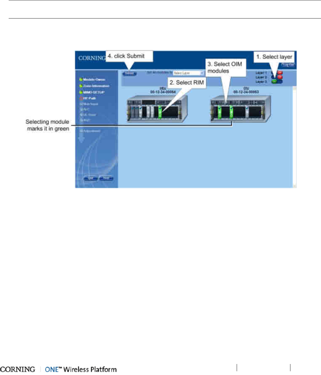
Commissioning the System
P/N 709C011801
Page 69
• For up to 3 groups (Layers 1-3) of services, where each group of services is transmitted only to RAUs connected to OIM
modules assigned to the layer:
o Set the Layer to be configured to On (green)
o Select a RIM module (will appear green)
NOTE: When a RIM-M module is selected the connected RIM module is automatically selected as well. The user must
verify that an RxU is installed before configuring the RF path with a MIMO pair.
o Select one OIM module or more to which the supported RIM service will be transmitted
o Click the Submit button. The configured modules will appear with a blue checkmark.
o Repeat for all RIM modules and additional layers
Figure 6-23. Configuring RF Paths for Layer
• To assign all modules to a single layer, where all RIM module services are transmitted through all of the OIM modules
and to their connected RAU units at the remote sites:
o Select a layer (Layer 1/2/3) in the Set All Modules to field.
o Click the Submit button. An "Are you sure you want to set all modules to layer…". message appears.
o Click OK.
Note the following:
• Only one layer can be configured/displayed at a time.
• Each RIM can be associated to all layers.
• Each RIM can be assigned to more than one OIM
• RIM and OIM modules which have been assigned to each other in a specific layer cannot be assigned to each other in
another layer. For example, if OIM #5, 8 and 9 are assigned to RIM #4 in Layer 1, they cannot be assigned to each
other in Layer 2. Upon selecting either RIM or OIMs the associated modules will be displayed transparently, indicating
unavailability for that layer.
9. Click Next to continue to the Max Input phase.
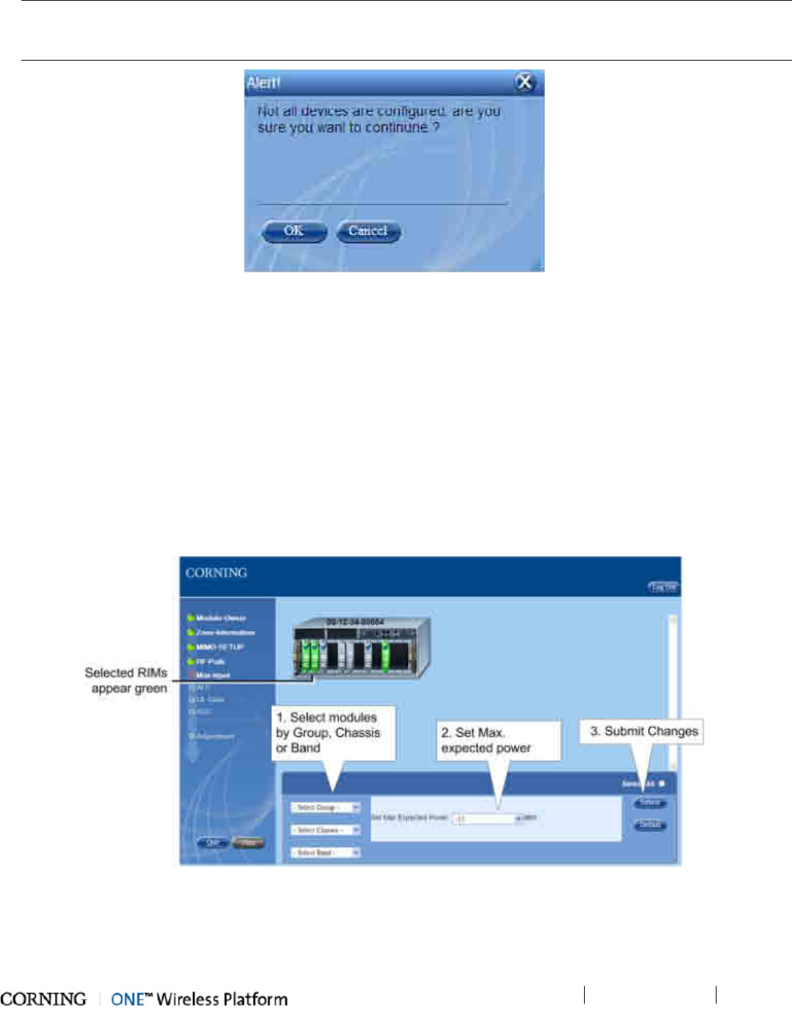
Commissioning the System
P/N 709C011801
Page 70
NOTE: If not all of the modules all configured before continuing to the next phase of the setup procedure the following alert
will appear: "Not all devices are configured, are you sure you want to continue?" Click OK to continue to Max Input or Cancel
to configure remaining devices.
Figure 6-24. Unconfigured Devices Alert Message
10. Set the BTS DL Max Expected Power for each RIM.
• Select the RIM(s) to be configured. All the RIMs can be selected simultaneously (Select All checkbox), individually or
according to Group (owner), Chassis or Band (service).
• Select the BTS DL Max Expected Power.
Note the following:
o Default Max. Expected Power = 30 dBm for unit protection
o Range: -15 dBm to 37 dBm in 1 dB steps
o PCS: 0 to 37 dBm
o A number of RIMs can be configured at a time, however if one of the selected RIMs has a limited range (e.g. PCS)
the Max. Expected Power allowed will be set according to limited range.
• Click Submit to apply setting.
Figure 6-25. Setting Max-Input Power
11. Click Next to continue to the ALC (Automatic Level Control) phase:
• Select the RIM(s) to be set. All the RIMs can be selected simultaneously (Select All checkbox), individually or according
to Group (owner), Chassis or Band (service).
• Enable (ON=default) or disable (OFF) the ALC operation for the selected RIM.
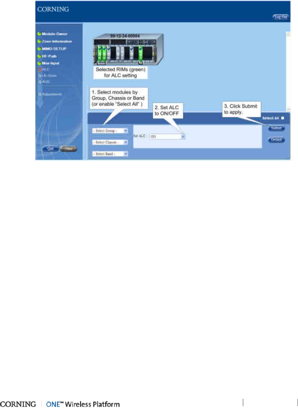
Commissioning the System
P/N 709C011801
Page 71
• Click Submit to apply setting.
Figure 6-26. Setting ALC
12. Click Next to continue to the UL-Gain phase. Set the Gain Mode for each RIM:
• Select the RIM(s) to be configured, either individually or according to Group, Chassis, or Band (selected Rims appear in
green).
• Set the Gain Mode for the selected RIM(s) to one of the following options:
o AutoSymmetrical (default): UL_gain_delta = band target power - max_exp_pwr
o Manual: select the value in the range of -19dB and +15dB (in 1dB steps).
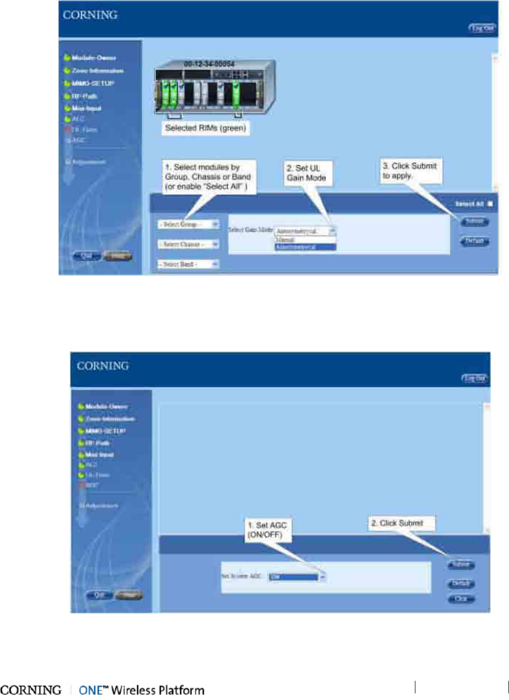
Commissioning the System
P/N 709C011801
Page 72
• Click the Submit button.
Figure 6-27. Setting UL-Gain (Manual)
13. Click Next to continue to AGC phase:
• Set System AGC (Automatic Gain Control): On (default)/Off.
• Click Submit to apply setting.
Figure 6-28. Setting AGC
14. Click Next to continue to Adjustment procedure phase. See System Adjustment Procedure (on page 73) section.
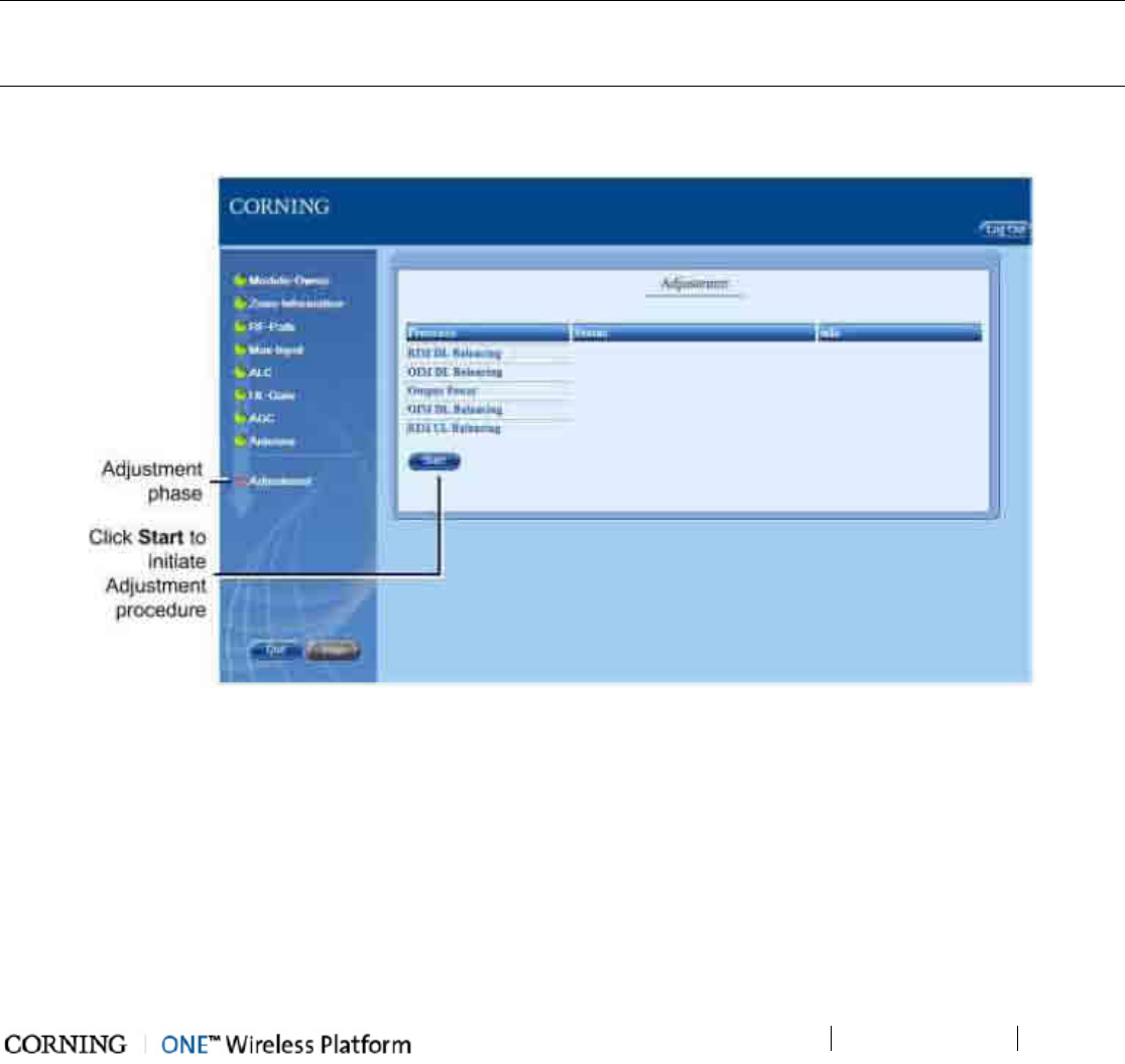
Commissioning the System
P/N 709C011801
Page 73
6.5 System Adjustment Procedure
The system Adjustment procedure phase is the last stage of the setup procedure.
The Adjustment procedure consists of the following processes:
• RIM DL Balancing – adjustment of unbalanced power loss at the RIM ports on the DL path to achieve the same required gain
from all RIM module outputs
• OIM DL Balancing – adjustment of unbalanced loss between different sectors on the DL path to achieve the same required
gain from all OIM modules outputs
• Output Power – adjustment of each service in the RAU/RXU so that they transmit the target output power
• RIM UL Balancing – adjustment of unbalanced power loss between all OIM modules towards the each RIM
• OIM UL Balancing - adjustment of unbalanced loss between different sectors on the UL path to achieve the same required
gain from all OIM modules output
NOTE: The user does not have to re-perform the complete setup procedure in order to re-perform the adjustment procedure (if
required at a later stage) – simply click Next in each setup stage until the Adjustment phase is reached. The Setup tool
remembers the last configuration for which it performed the adjustment procedure.
To Initiate the Adjustment Procedure
1. Click the Start button in the Adjustment phase screen.
Figure 6-29. Adjustment Phase Screen
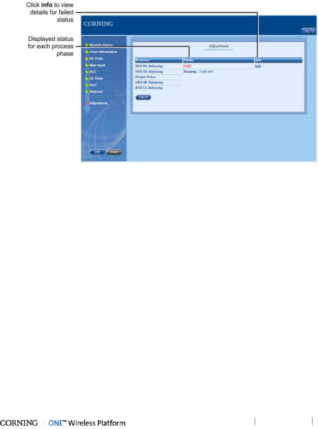
Commissioning the System
P/N 709C011801
Page 74
2. The Adjustment procedure runs through the five process phases where the status is displayed for each process.
Figure 6-30. Running the Adjustment Procedure
3. For failed processes – click the info link in the adjacent column to view the fail status details.
4. Upon successfully completing the Adjustment procedure the user can exit the Setup tool and monitor the system and the
individual ONE™ solution devices through the Config GUI.
5. The balancing procedure will begin and balance each module in the system.
6. Components that have failed the commissioning procedure will be shown in red as FAILED. Click the info button to
determine the reason the component failed (see section 7.1).
6.6 About the Setup Tool
The Setup Tool automates the commissioning procedure for the ONE™ system. The user is prompted to use the Setup Tool upon
one of the following:
• Non-configured module/device discovered
• Non-adjusted module/device discovered
• Erroneous adjustment termination of a module detected
• Adjustment time stamp mismatch between HCM and module information
• User request
The Setup tool consists of 3 main stages:
1. Commissioning – the user assigns RIM modules to pre-defined groups (e.g. indicating carriers), defines zone information
for modules, configures the RF paths for up to three layers (sectors) and RF parameters configuration.
2. Adjustment Procedure – automatic adjustment procedure performed according to the user configuration performed in
previous steps
3. Reports stage – presents the commission process results.
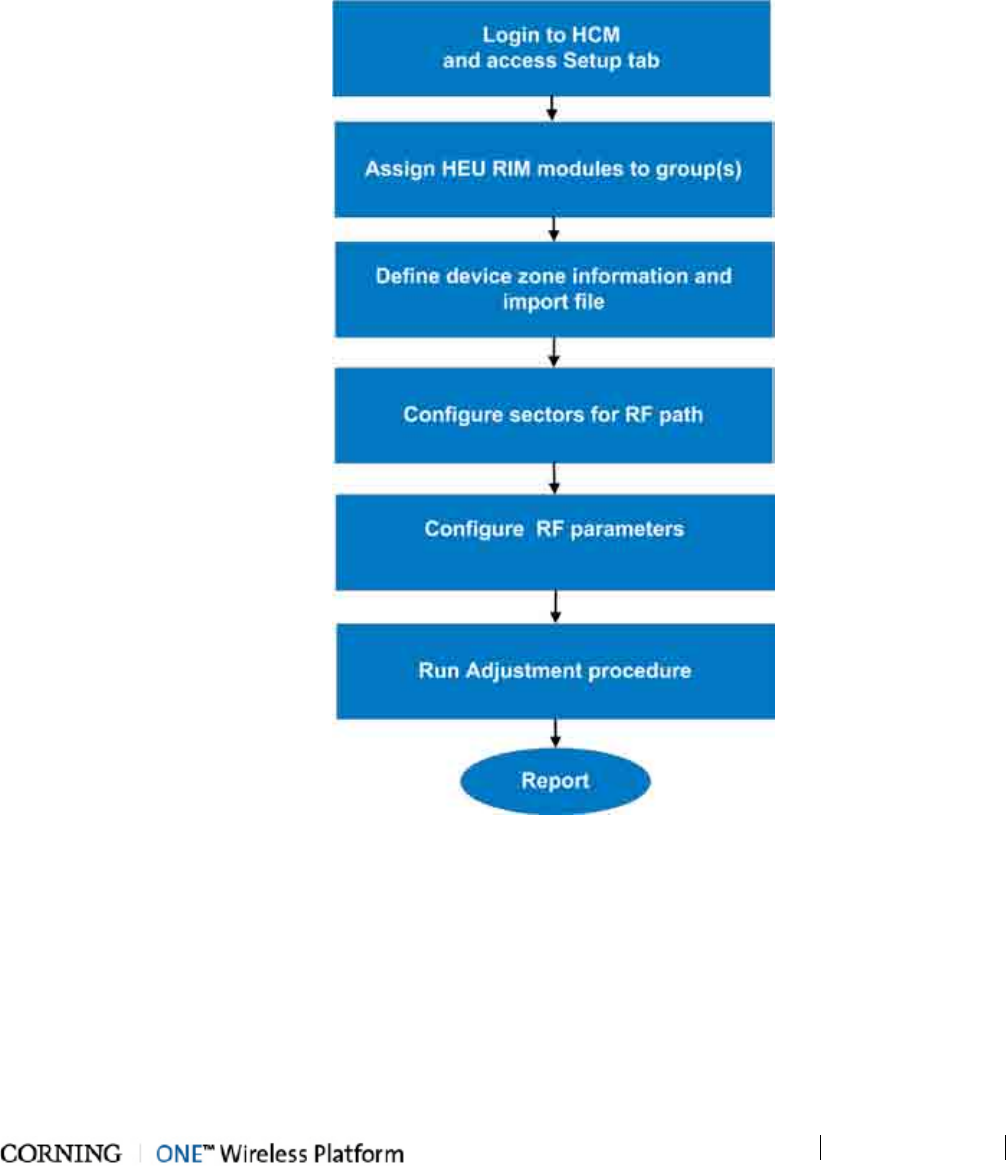
Commissioning the System
P/N 709C011801
Page 75
How does it work?
• When a Web access session is opened, the system automatically detects the existence of uncommissioned devices and
provides a notification message to the user.
• The user can then launch the Setup Tool by clicking the Setup tab.
• The user is prompted through various GUI screens which display the required parameters and information for configuration.
• Upon completion, the user can view a report for each Failed adjustment phase
6.6.1 Overview of Setup Procedure
Figure 6-31. Setup Procedure Overview
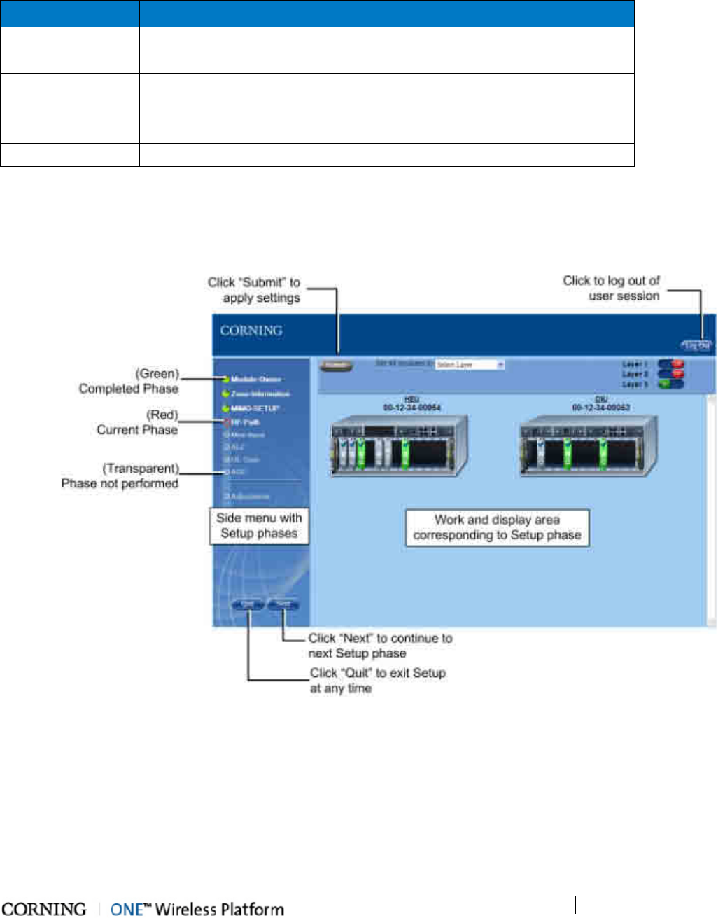
Commissioning the System
P/N 709C011801
Page 76
6.6.2 Default Values Assigned in Setup Tool
Each phase of the Setup Tool consists of configuring various parameters or settings, where default values are provided, enabling
the user to continue to the next phase can if no other user input is given. Refer to the following table for the default values.
Parameter Default Value
RF Path All modules allocated to Layer 1
Max-Input to RIM 37 dBm (RIM level)
ALC ON (RIM level)
UL-Gain Autosymetrical
AGC 0 (system level)
Antenna Internal (system level)
Table 6-4. Default System Values
6.6.3 Navigating the Setup Tool
The following figure shows one of the Setup screens with the main features and options common for all setup screens.
Figure 6-32. Example of Setup Screen (RF-Path Phase)
Navigating the Setup Tool
• The process comprises several phases that are displayed in a menu to the left of the screen. The current phase is indicated
by a red circle, where each completed phase shows a green status indicator.
• Default values are assigned to all the screen parameters, allowing the user to proceed to the next phase without having to
configure or modify the parameters (if are appropriate for site requirements).
• After the Setup procedure has been run at least once, the user can skip phases using the "Next" button until the required
phase is reached.
• The user can quit the Setup procedure any time (using the Quit button) and access the tool at any time (using the Setup tab).

Commissioning the System
P/N 709C011801
Page 77
• The user cannot toggle between Setup operation and other screens while the Setup tool is running. To access configuration
screens of specific devices, it is required to quit the Setup procedure. The Web GUI management application will appear.
• The module information (e.g. Serial No., Slot, Band, etc.) can be viewed by pointing on the module (module property window
will appear on bottom left of screen).
Color legend
The colors in which the RIM/OIM modules and LEDs appear in the setup device view provide the status indications:
Item Color Status
RIM/OIM module Green Selected
Grey Not selected
Transparent Disconnected
LED Blue Checkmark
Assigned/Configured
Table 6-5. Module and LED Color Legend
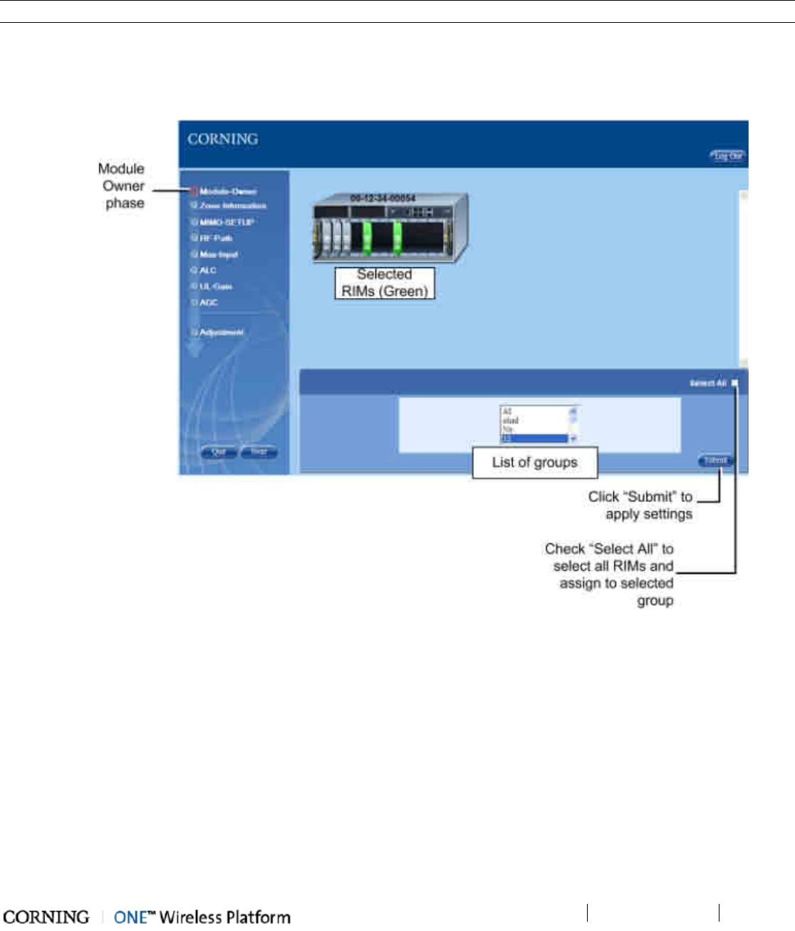
Commissioning the System
P/N 709C011801
Page 78
6.6.3.1 Module Owner
The Module Owner phase enables the user to assign the (HEU) service specific RIM modules to groups (usually corresponding
to operators).
NOTE: The groups must be created before running the Setup Tool - see Defining User Groups (on page 107) section.
After a RIM module has been assigned to a specific group, only a user from that group will have access to the RIM. In addition,
the Setup Tool enables assigning all of the RIM module to all of the groups ("All" option in group list) so that they are all
accessible to everyone.
The default setting for this phase is that all RIMs are shared (group=All).
Figure 6-33. Module Owner Screen
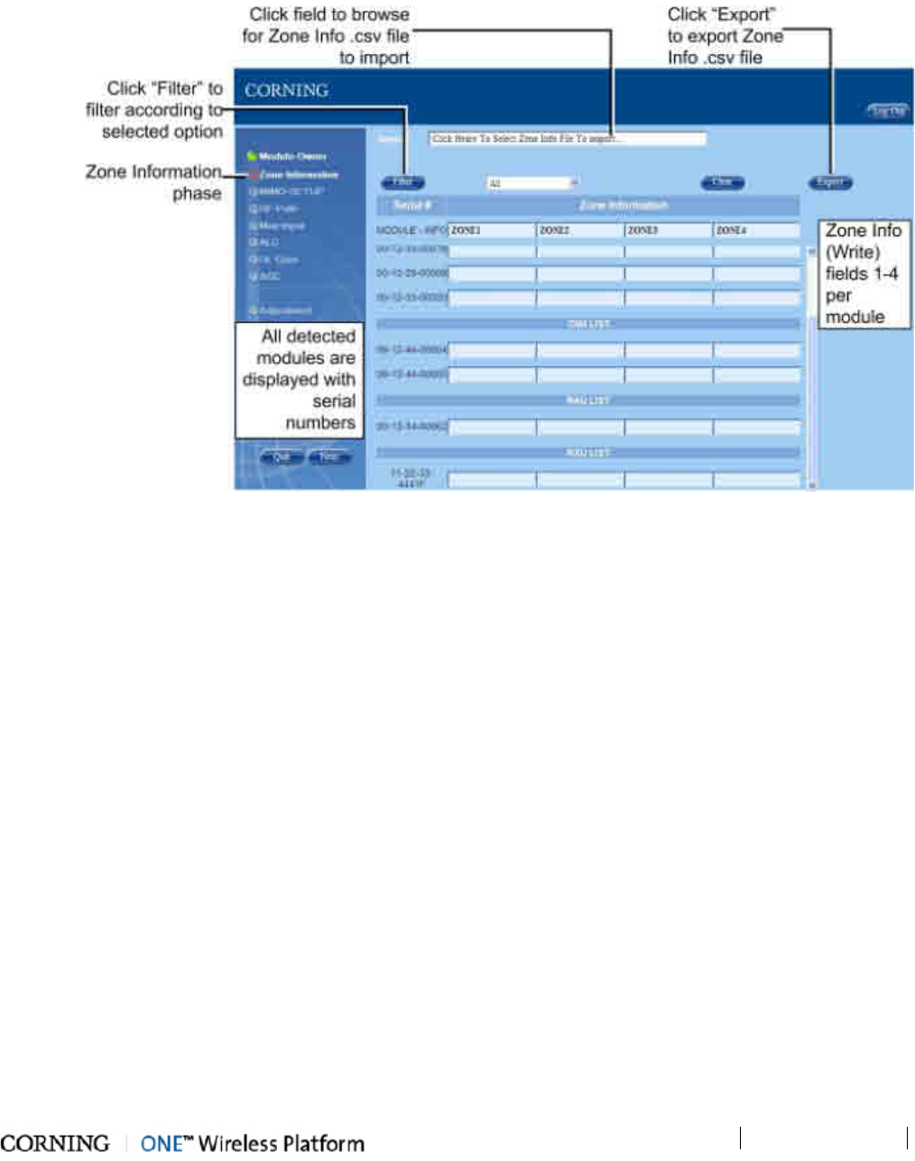
Commissioning the System
P/N 709C011801
Page 79
6.6.3.2 Zone Information
The Zone Information phase enables the user to label each unit in the system to help classify and locate the different units with
ease. An example of zone information defined for an RAU can be: Building 1; Floor 1; Room 1. The zone information defined in
this phase will appear in the Module Info tab (Read-Only) of the device in the Web GUI Management (Config).
Figure 6-34. Zone Information Screen
• All of the detected devices for configuration appear in the Zone Information screen. The devices are displayed according to
module type along with their serial number.
• The displayed devices can be filtered according to module type, chassis, etc.
• The zone information consists of a 4 field structure and should be defined so that it provides an indication of the exact
location of the device. This will facilitate easily locating the device if troubleshooting or maintenance is required.
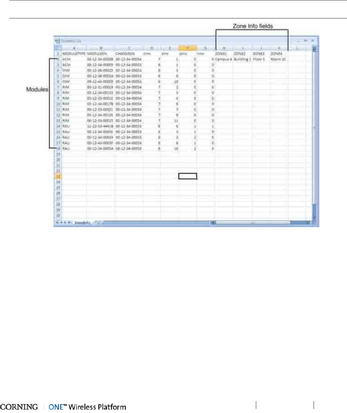
Commissioning the System
P/N 709C011801
Page 80
The user is provided with two options for configuring the zone information:
• Entering the zone info in the ZONE1 to ZONE4 fields of each module in the Setup Tool Zone Information screen
• Importing a Zone Information .csv file with all the zone information for each module
NOTE: Upon initial setup, requires first exporting a .csv file and entering all of the information. The CSV file is stored on the
HCM of the master HEU. It can be exported to a local PC and be saved for later reference, or imported into the HCM.
Figure 6-35. Example of Zone Information CSV File
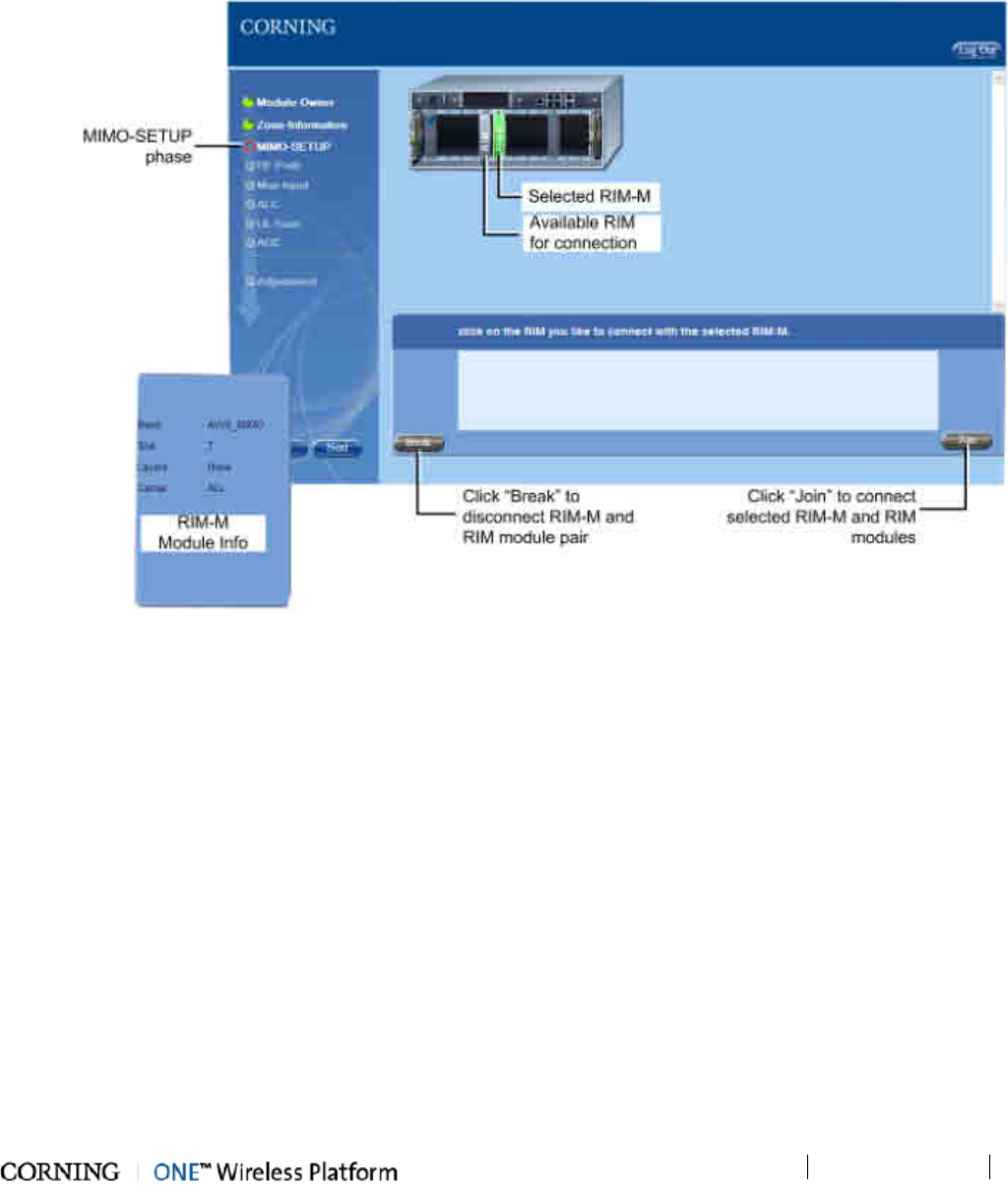
Commissioning the System
P/N 709C011801
Page 81
6.6.3.3 MIMO-SETUP
The MIMO-SETUP phase enables the user to configure the RIM modules for the MIMO paths. The user is required to connect
pairs of RIM-M and RIM modules supporting the same band (e.g. AWS) which will then be extended to the corresponding RAU
(via the OIM).
Figure 6-36. MIMO Setup Procedure
• Only one RIM-M can be connected to a specific RIM.
• When a RIM-M is selected, the available and compatible RIM modules will appear in grey. Incompatible/unavailable RIM
modules will appear transparent.
• Before configuring an RF path (connecting with OIM) with a RIM-M and RIM pair, the installation of an RxU must be verified.
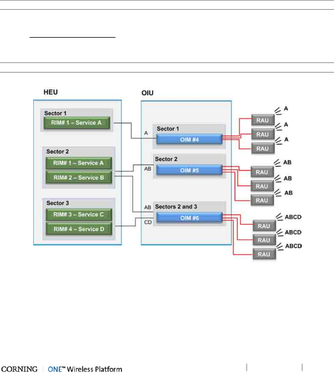
Commissioning the System
P/N 709C011801
Page 82
6.6.3.4 RF Path
In the RF Path phase, up to three groups of services (Sectors) can be configured, where each sector consists of a number of
services (RIM). A RIM can belong to any or all of the sectors at the same time and each OIM module can then be assigned one
or more of the sectors in any combination. (The same RIM service cannot be allocated to the same OIM in multiple sectors). The
RAU modules hosted by each OIM distributed the services routed by the host OIM.
NOTE: In the GUI, Sectors are referred to as Layers (Layer-1, Layer-2 and Layer-3).
The following block diagram illustrates an example of three configured RF Paths (Layers):
• Sector 1 - consists of Service A and is routed only to OIM #4 to the hosted RAU modules. See example of configuration via
GUI in RAU Configuration – section 7.4.
• Sector 2 – consists of Service A and B and is routed to OIM#5 and to OIM #6, to the hosted RAU modules
• Sector 3 – consists of Service A, B, C and D and is routed to OIM #6, to the hosted RAU modules
NOTE: RIMs and OIMs can be assigned to Layers in any combination.
Figure 6-37. Example of RF Path Allocation
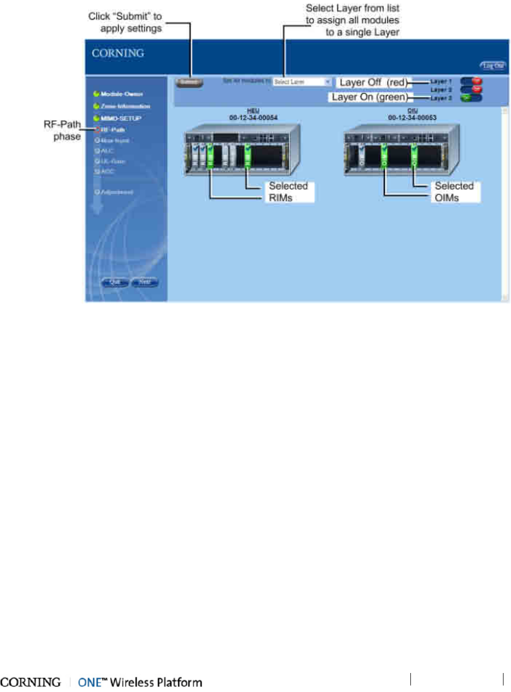
Commissioning the System
P/N 709C011801
Page 83
The following figure shows the RF-Path phase screen.
Figure 6-38. RF-Path Phase Screen
Note the following:
• RF-Path phase default settings:
• Layers 1-3 - Off
• (HEU) RIM and (OIU) OIM modules - appear transparent ("ghost")
• A number of RIMs can be associated with an OIM on each Layer
• One RIM can be associated with a number of OIMs on a Layer
• When selecting a RIM-M, the connected RIM is automatically selected as well and configured for the same Layer.
• A RIM associated with an OIM in Layer 1 cannot be associated with the same OIM in Layer 2 or 3 (and vice versa)
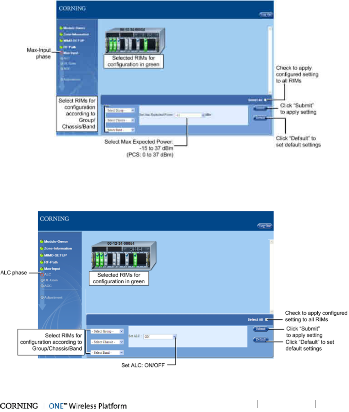
Commissioning the System
P/N 709C011801
Page 84
6.6.3.5 Max Input
The Max Input phase is used to set the BTS DL Max Expected Power for each RIM. The following figure shows the Max-Input
phase screen.
Figure 6-39. Max-Input Phase Screen
6.6.3.6 ALC
The ALC phase of the Setup procedure enables the user to enable or disable the ALC (Automatic Level Control) function for each
RIM module (Default=On). The following figure shows the ALC phase screen.
Figure 6-40. ALC Phase Screen
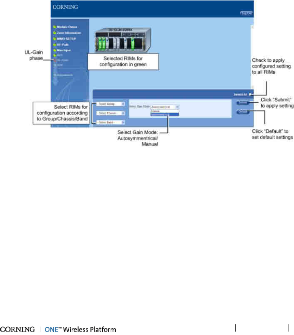
Commissioning the System
P/N 709C011801
Page 85
6.6.3.7 UL Gain
The UL-Gain phase of the Setup Tool is used to set the system UL gain control. There are two modes:
• Autosymmetrical gain setting (default): UL Gain Delta=Band Target Power - Max Exp. Power
• Manual gain setting: UL Gain delta=User definition (gain range value between -19 to +15 dB)
The following figure shows the UL Gain screen.
Figure 6-41. UL Gain Phase Screen
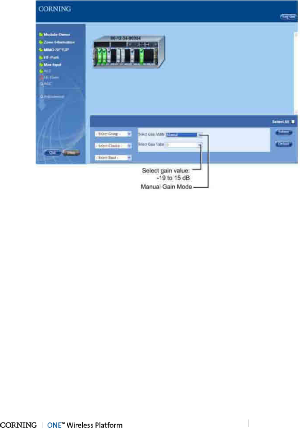
Commissioning the System
P/N 709C011801
Page 86
Figure 6-42. UL Gain Phase Screen - Manual Gain Mode
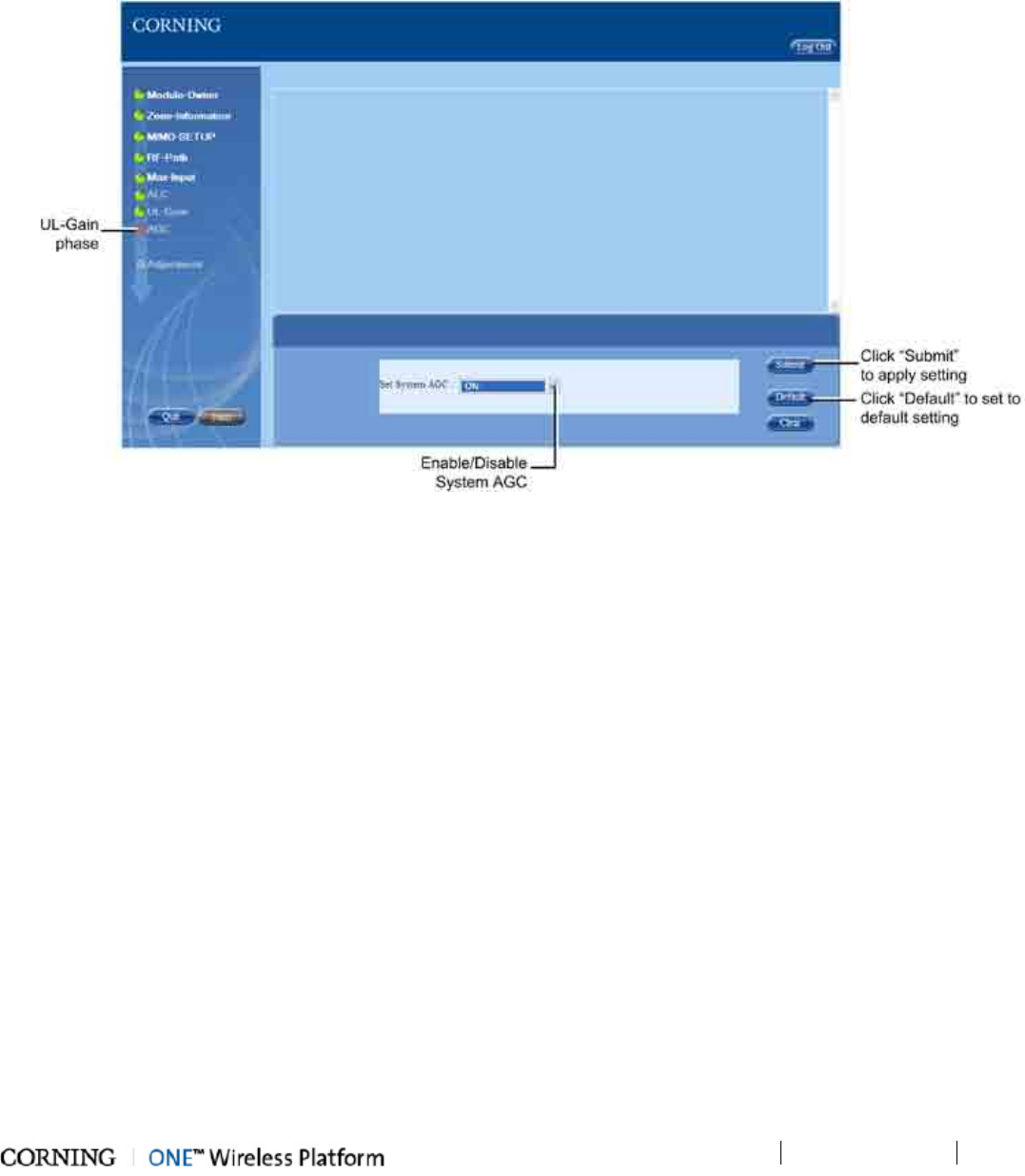
Commissioning the System
P/N 709C011801
Page 87
6.6.3.8 AGC
The AGC phase of the Setup Tool enables the user to enable/disable the AGC (Automatic Gain Control) function (system level)
for the uplink and downlink. The following figure shows the AGC phase screen.
Figure 6-43. AGC Phase Screen
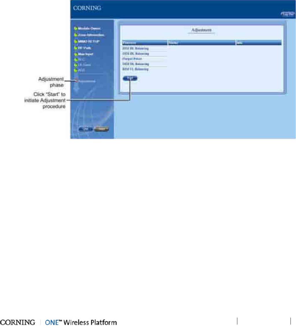
Commissioning the System P/N 709C011801 Page 89
6.6.3.9 Adjustment
The Adjustment phase performs the adjustment procedure for the uplink and downlink gain of the RIMs and OIMs, as well as
adjusting the target output power of the services transmitted from the RAU/RxU.
The Adjustment procedure is initiated upon clicking the "Start" button in the screen. The following figure shows the Adjustment
phase screen.
Figure 6-44. Adjustment Phase Screen
There are six processes, where the status for each one is displayed i the adjacent field. A detailed description of a failed status
can be viewed by clicking on the "Info" link of the process. This can be sued as reference for troubleshooting the failed process.
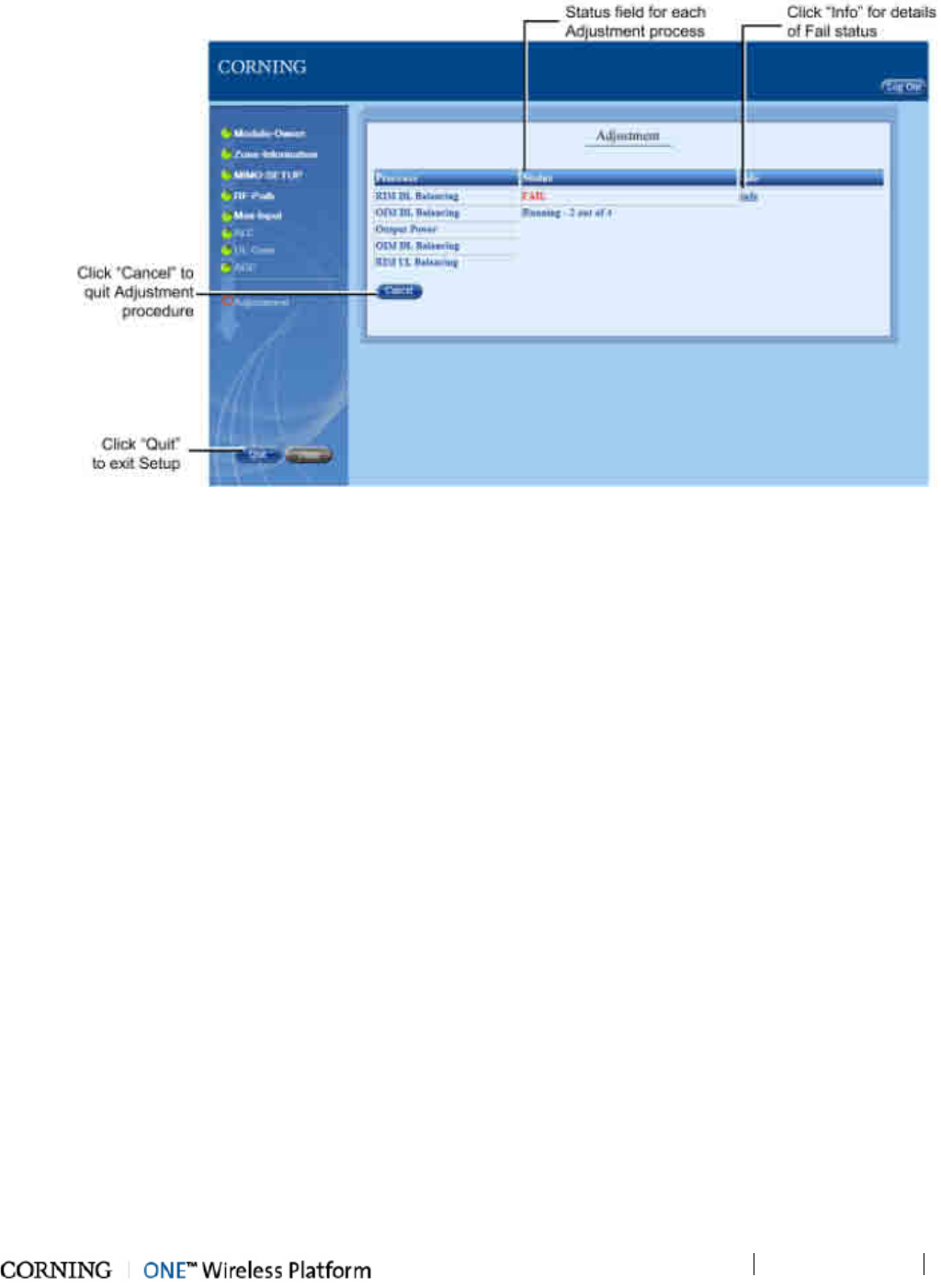
Commissioning the System P/N 709C011801 Page 90
Figure 6-45. Adjustment Phase Screen - Running Procedure
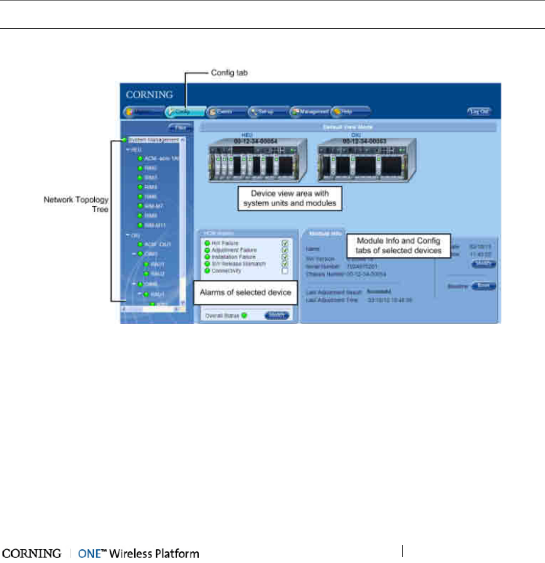
Device Configuration
P/N 709C011801
Page 91
7 Device Configuration
After successfully commissioning the system and performing the setup procedure (using the Setup Tool), you may now proceed
with (manually) fine tuning and modifying device parameters to suit the site needs via the Web GUI Management application.
The manual configuration and monitoring options are accessed via the Config tab, which provides dedicated configuration tabs
for each device/module.
NOTE: The monitoring and device alarms are described in detail in the Monitoring and Troubleshooting (on page 122)
section.
To configure, view and modify device parameters, click on any of the device elements appearing in the topology tree, or on the
icons in the device view. The corresponding Module Info and configuration option tabs will appear.
Figure 7-1. Web Management GUI - Example of Config Screen
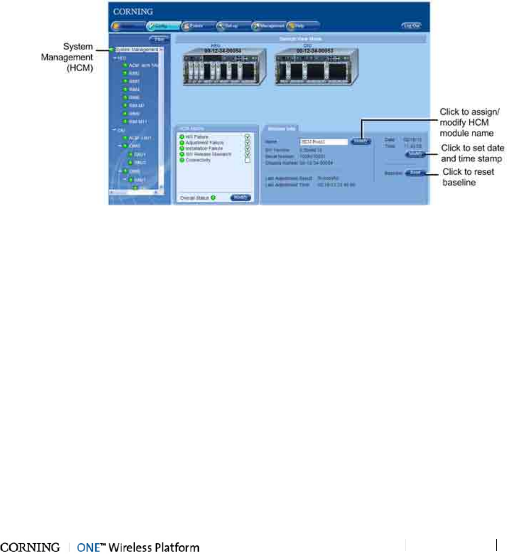
Device Configuration
P/N 709C011801
Page 93
7.1 System Management (HCM)
The System Management element is the root element of the Network Topology Tree and is representative of the (HEU) HCM
module. Upon selecting the System Management element, all of the HEU and connected OIU chassis (including RIM and OIM
modules) are displayed in the device view area.
The System Management Config screen also displays the HCM Alarms tab (see section System Management (HCM) Alarms for
details) and the Module info tab.
Figure 7-2. System Management Config Screen
The Module Info tab displays the HCM general information (e.g. SW version, S/N, Adjustment result, etc.) and provides the
following options:
• Assigning the HCM an indicative name (or modifying) - click (Name) Modify button, enter name and click OK. Name will
appear in Network Topology.
• Setting the Time and Date stamp - click (Date/Time) Modify button, set date and time and click OK.
• Resetting (Refresh) baseline (see Removing a Hosted Device from Baseline (on page 103) for details) - click (Baseline)
Reset button.
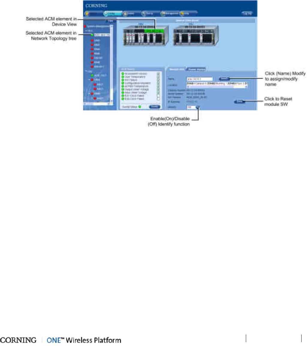
Device Configuration
P/N 709C011801
Page 94
7.2 HEU Configuration
The HEU configuration consists of defining parameters for the ACM (Auxiliary Controller Module) and for each installed RIM (RIM
Interface Module), where each module is configured through dedicated configuration options tabs.
7.2.1 HEU ACM
To access the (HEU) ACM, click on the ACM hosted by the HEU in the Network Topology or in the device view area. The ACM
Config pane appears and includes the ACM Alarms (detailed description in HEU (ACM) Alarms section), Power Alarms (detailed
description in ACM Power Alarms section) and Module Info tabs.
Figure 7-3. (HEU) ACM Config Screen
The (HEU) ACM Module Info tab provides the following:
• Module Name (R/W) - click Modify button, enter name and click OK. Name will appear in corresponding field and adjacent
to the device element in the Network Topology Tree.
• General Info (Read-Only) - module information such as Location (defined via Setup Tool - see Zone Information section
for details (on page 78), and S/N, IP address, etc.
• Identify option - when this option is turned On, the corresponding LED on the physical HW (identified as HCM) flickers
rapidly, enabling the physical location to be detected.
• Reset button - enables resetting the module SW by remote
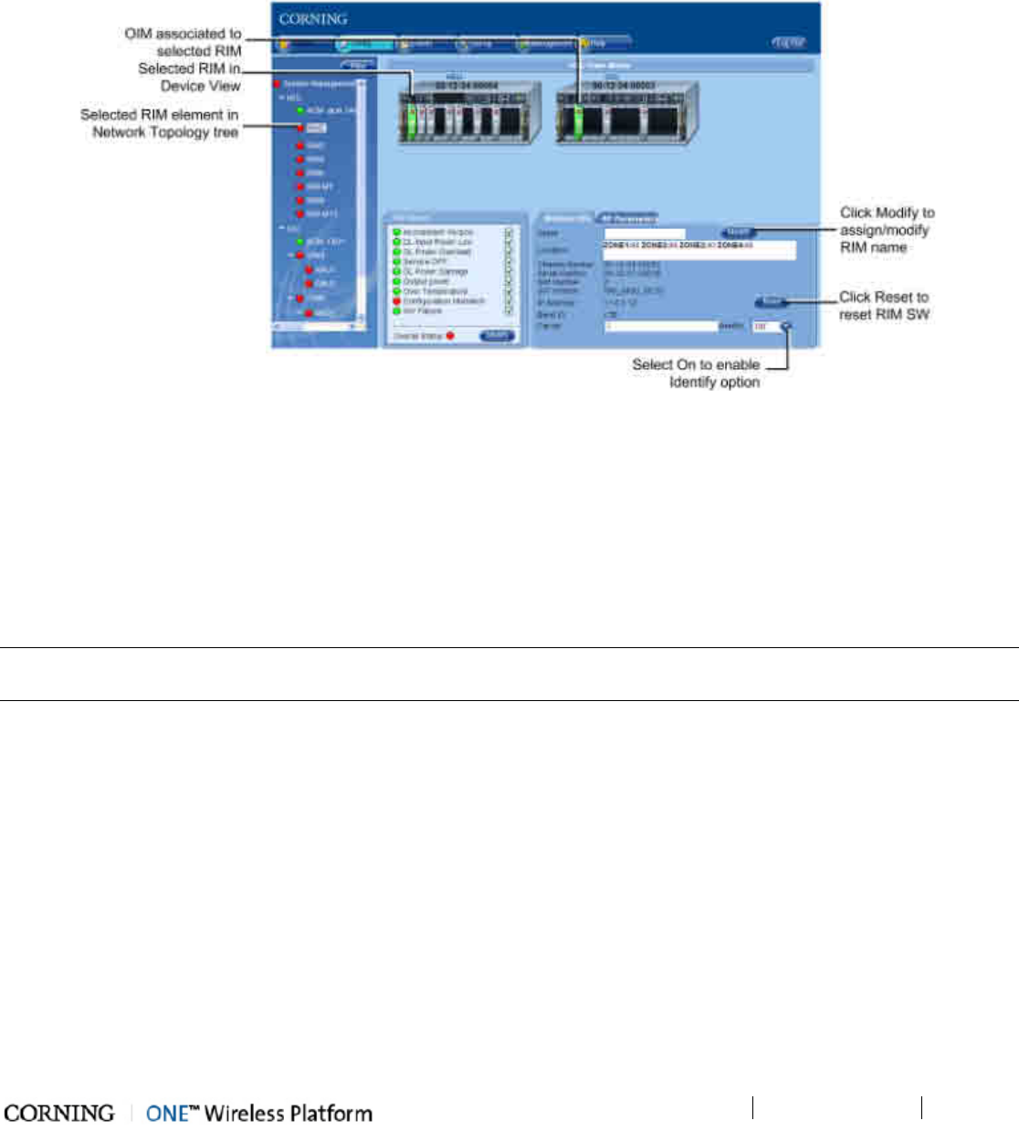
Device Configuration
P/N 709C011801
Page 95
7.2.2 RIM
Each RIM must be configured individually through its' dedicated Config tabs.
To configure RIM
1. Click on the RIM in the Network Topology or in the device view area. The Module Info tab is displayed by default. The
selected RIM (and associated OIM) will appear green in the Device View area.
Figure 7-4. RIM Module Info Tab
The Module Info tab includes general information (R/O) such as Location (defined during Setup procedure), S/N, Band,
Carrier, etc.
2. (Optional) Assign RIM name (if not already assigned):
• Click (Name) Modify button
• Enter indicative name in field
• Click OK
• Assigned name will appear in the Name filed and in the topology tree
NOTE: The Module Info tab includes a Reset button (module SW reset) and Identify function which when turned to On causes
corresponding LED on physical module to flicker rapidly enabling to detect the physical location.
3. Click on the RF Parameters tab. The following tab appears.
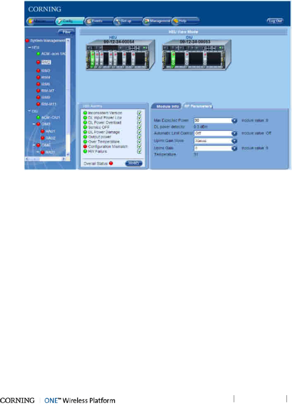
Device Configuration
P/N 709C011801
Page 96
Figure 7-5. RIM RF Parameters Tab
4. Configure RF parameters according to site settings:
• Max Expected Power - set the BTS DL Max Expected Power:
o Default Max. Expected Power = 30 dBm for unit protection
o Range: -15 dBm to 37 dBm in 1 dB steps
o PCS: 0 to 37 dBm
• Automatic Limit Control (ALC) - enable (On=default)/ disable (Off) ALC function for RIM
• Uplink Gain Mode - set the Gain Mode for the selected RIM:
o AutoSymmetrical (default): UL _gain_delta = band target power - max_exp_pwr
o Manual: select the value in the range of -19dB and +15dB (in 1dB steps)
• Uplink Gain - set UL gain value between -19 to 15 dB (in 0.5 dB steps)
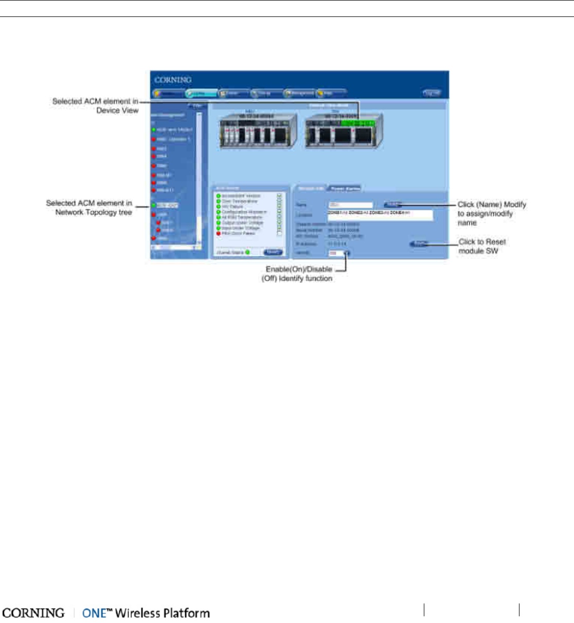
Device Configuration
P/N 709C011801
Page 97
7.3 OIU Configuration
The OIU configuration consists of defining parameters for the ACM (Auxiliary Controller Module) through which the unit is
controlled and managed and for each installed OIM (Optical Interface Module). Each module is configured through dedicated
configuration options tabs.
7.3.1 OIU ACM
NOTE: The ACM Module Info and Power Alarms are the same for modules installed in either HEU or OIU chassis.
To access the (HEU) ACM, click on the ACM hosted by the HEU in the Network Topology or in the device view area. The ACM
Config pane appears and includes the ACM Alarms (detailed description in HEU (ACM) Alarms section), Power Alarms (detailed
description in ACM Power Alarms section) and Module Info tabs.
Figure 7-6. (OIU) ACM Config Screen
The (OIU) ACM Module Info tab provides the following:
• Module Name (R/W) - click Modify button, enter name and click OK. Name will appear in corresponding field and adjacent
to the device element in the Network Topology Tree.
• General Info (Read-Only) - module information such as Location (defined via Setup Tool - see Zone Information section
for details (on page 78), and S/N, IP address, etc.
• Identify option - when this option is turned On, the corresponding LED on the physical HW (identified as HCM) flickers
rapidly, enabling the physical location to be detected.
• Reset button - enables resetting the module SW by remote
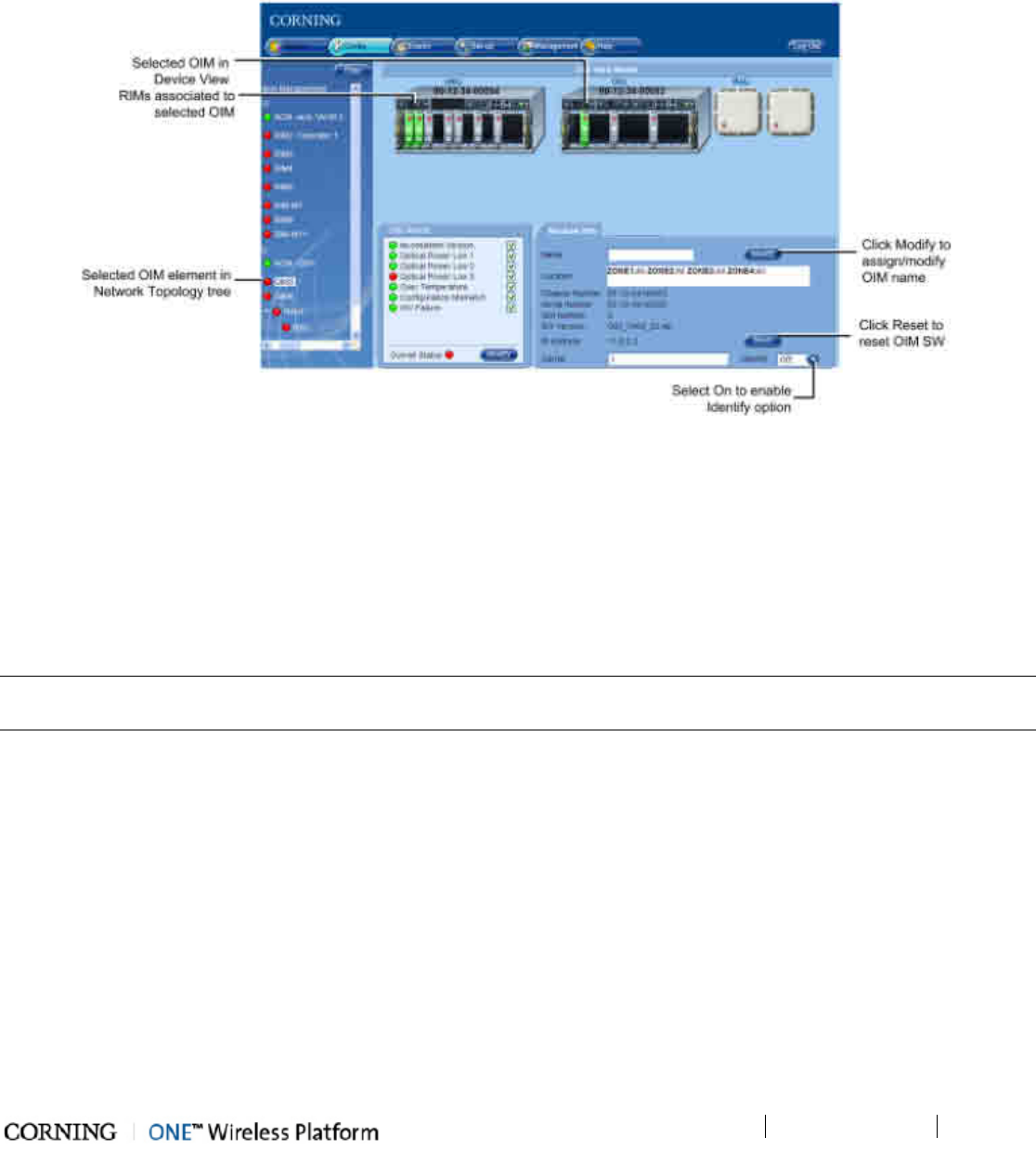
Device Configuration
P/N 709C011801
Page 98
7.3.2 OIM
The OIM configuration only consists of assigning the OIM an indicative name (optional).
To configure OIM
1. Click on the OIM in the Network Topology or in the device view area. The Module Info tab is displayed by default. The
selected OIM (and associated RIMs) will appear green in the Device View area.
Figure 7-7. OIM Module Info Tab
The Module Info tab includes general information (R/O) such as Location (defined during Setup procedure), S/N, Band,
Carrier, etc.
2. (Optional) Assign OIM name (if not already assigned):
• Click (Name) Modify button
• Enter indicative name in field
• Click OK
• Assigned name will appear in the Name filed and in the topology tree
NOTE: The Module Info tab includes a Reset button (module SW reset) and Identify function which when turned to On causes
corresponding LED on physical module to flicker rapidly enabling to detect the physical location.
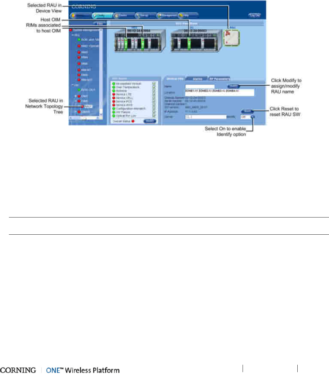
Device Configuration
P/N 709C011801
Page 99
7.4 RAU Configuration
To configure the RAU
1. Click on the RAU in the Network Topology (under the hosted OIM) or in the device view area. The Module Info tab is
displayed by default. The selected RAU (and associated OIM) will appear green in the Device View area.
Figure 7-8. RAU Module Info Tab
The Module Info tab includes general information (R/O) such as Location (defined during Setup procedure), S/N, Carrier,
etc.
2. (Optional) Assign RAU name (if not already assigned):
• Click (Name) Modify button
• Enter indicative name in field
• Click OK
• Assigned name will appear in the Name filed and in the topology tree
NOTE: The Module Info tab includes a Reset button (module SW reset) and Identify function which when turned to On
causes corresponding LED on physical module to flicker rapidly enabling to detect the physical location.
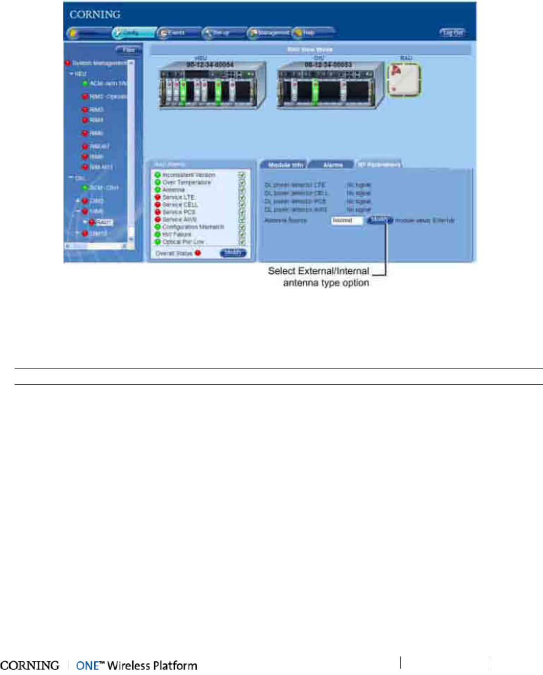
Device Configuration
P/N 709C011801
Page 100
3. Click on the RF Parameters tab. The following tab appears.
Figure 7-9. RAU RF Parameters Tab
The RAU RF Parameters tab includes the input power (dBm) measured by the DL power detector for each service and
the RAU Antenna Source option.
4. The Antenna Source type is set to Internal by default. To change to External - click the Modify button, select External
option and click OK.
NOTE: make sure that an external antenna is connected to the RAU.
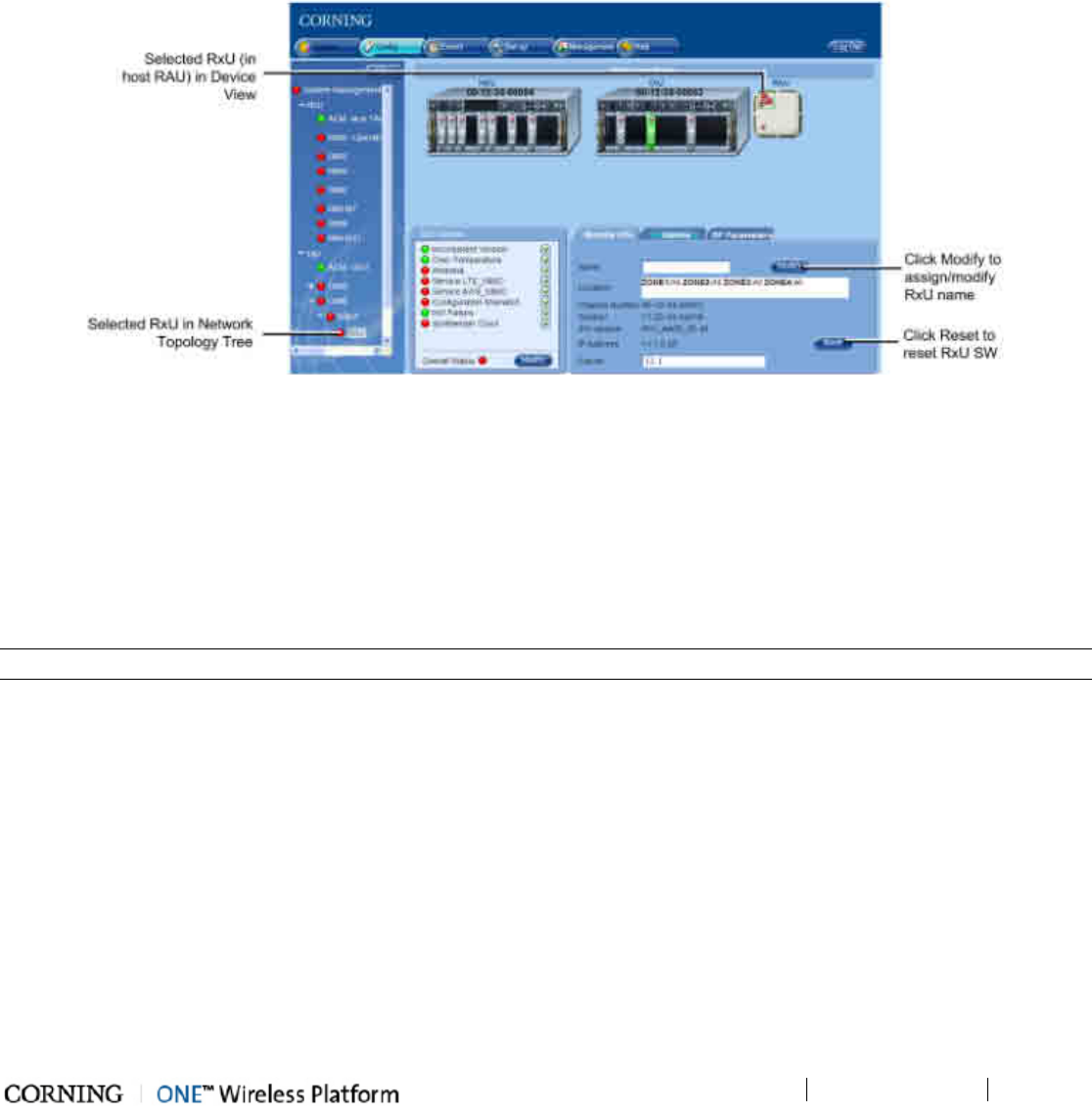
Device Configuration P/N 709C011801 Page 101
7.5 RxU Configuration
To configure the RxU
1. Click on the RxU in the Network Topology (under the hosted RAU) or in the device view area. The Module Info tab is
displayed by default. The selected RxU (and associated RAU and OIM) will appear green in the Device View area.
Figure 7-10. RxU Module Info Tab
The Module Info tab includes general information (R/O) such as Location (defined during Setup procedure), S/N, Carrier,
etc.
2. (Optional) Assign RxU name (if not already assigned):
• Click (Name) Modify button
• Enter indicative name in field
• Click OK
• Assigned name will appear in the Name filed and in the topology tree
NOTE: The Module Info tab includes a Reset button (module SW reset).
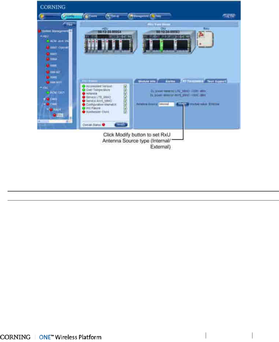
Device Configuration P/N 709C011801 Page 102
3. Click on the RF Parameters tab. The following tab appears.
Figure 7-11. RxU RF Parameters Tab
The RxU RF Parameters tab includes the input power (dBm) measured by the DL power detector for each MIMO service
and the RxU Antenna Source option.
4. The Antenna Source type is set to Internal by default. To change to External - click the Modify button, select External
option and click OK.
NOTE: make sure that an external antenna is connected to the RxU.

Device Configuration P/N 709C011801 Page 103
7.6 Removing a Hosted Device from Baseline
The System Management application automatically detects system elements physically connected to it and adds it to the
base-line. When the communication with a device is faulty (i.e. the device is disconnected) an alarm is generated. Therefore,
when removing (disconnecting) a hosted device from the system, the base-line must be re-set in order to update the removal
and to prevent an alarm from being raised.
To Perform Reset the Baseline
1. Double-click on the System Management root in the Network Topology. The HCM Module Info tab is displayed.
2. Click (Baseline) Reset button to set new baseline that does not include the disconnected device.
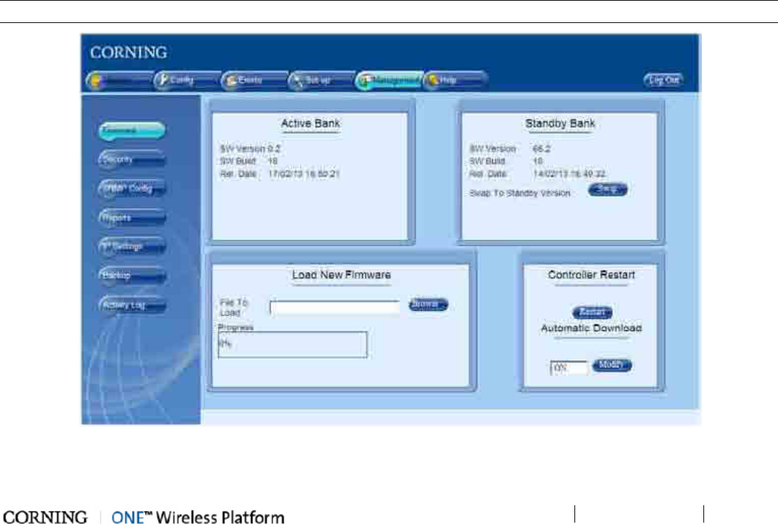
Administration
P/N 709C011801
Page 105
8 Adminis tration
This chapter describes the administrative options supported by the ONE™ system. These include:
• IP and SNMP settings
• Creating and managing multi-user account groups
• Configuration backup and restore
• Software version upgrades
• Viewing information on devices and various modules
• Viewing the activity logs
The administrative operations described in this chapter are accessed from the Management Menu Tab (on page 105).
8.1 Management Menu Tab
The Management menu tab provides access to all the administrative options described in this chapter (in addition to other
options that are described in detail in other chapters).
To access the Management menu options
Click the Management tab. The Management tab sidebar lists the available sub-options. The Firmware page is selected by
default. The options in the table following the figure, are described in the order that they appear in the sub-menus.
NOTE: Some of the options are described in detail in other chapters where the descriptions are (more) relevant.
Figure 8-1. Management tab and Sub-menus
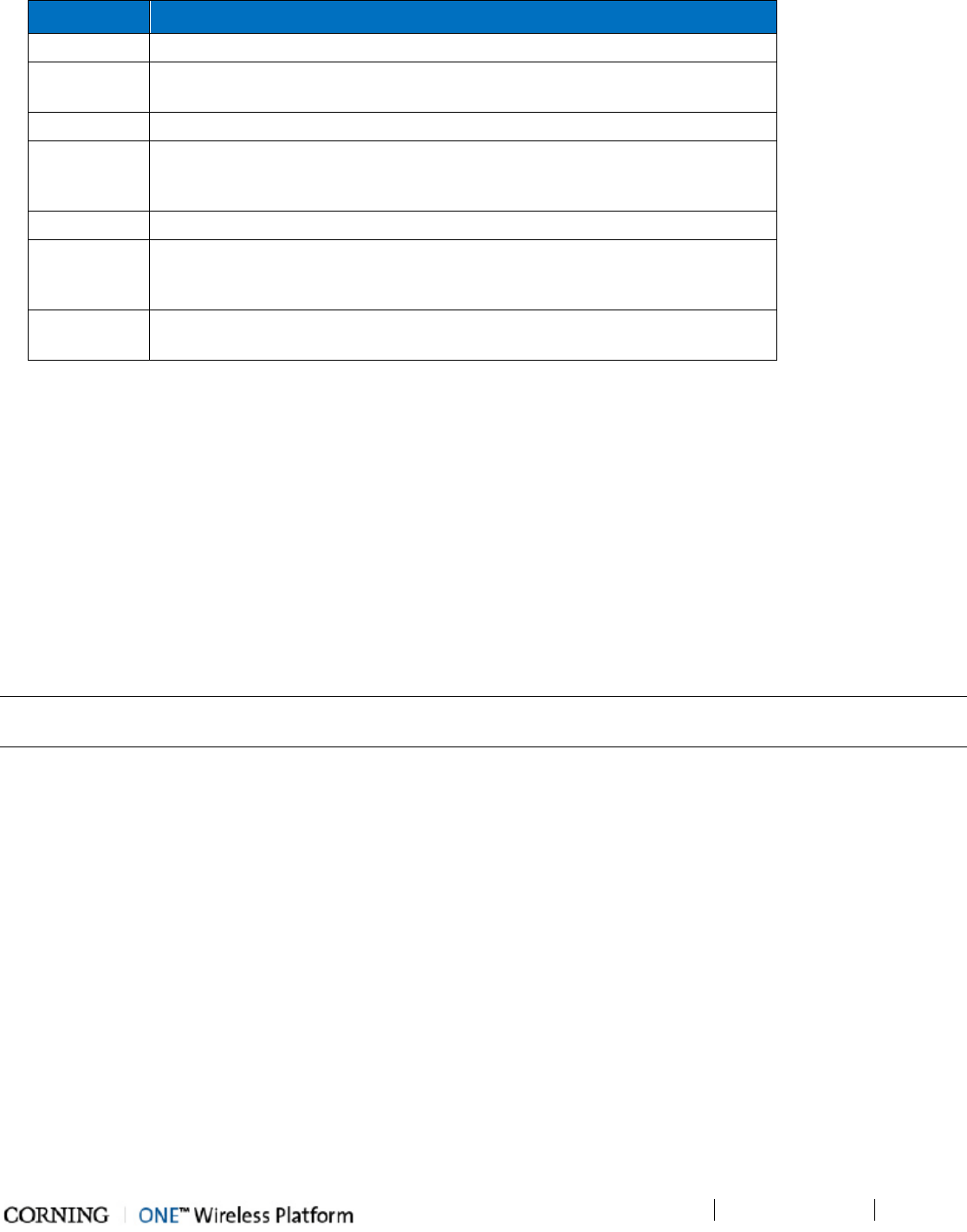
Administration
P/N 709C011801
Page 106
Options Descriptions
Firmware HEU HCM firmware upgrade. See Firmware Upgrade (on page 120).
Security Creating and managing multi-user account groups and monitoring user activities.
See Multi User Account Management (on page 106).
SNMP Config For using any SNMP manager. See SNMP Config (on page 137).
Reports Summary information on various types of devices in the network along with basic
physical and configuration information on each device. See Generating Device
Reports (on page 117).
IP Settings IP Settings for the HCM (HEU control and management unit).
Backup Backup of the configuration of the HEU and all hosted devices to a selected
location and restore saved configuration of HEU and hosted devices. See Backup
& Restore.
Activity Log A security measure used to monitor user operations such as configuration
changes. See Activity Log (on page 120).
Table 8-1.Management Tab Menu Options
8.2 Multi User Account Management
Access security is based on the definition of a number of user groups created by the system administrator. Groups are used to
limit access to specific devices so that only devices allocated to a group are accessible by members of that group. Each group is
automatically assigned a group administrator as it is created. Each group administrator creates user accounts for his/her group,
where the user accounts in each group can be of various authentication levels (five hard-coded authentication levels are
available).
The system management (HCM) platform supports up to 31 groups, which can be assigned to up to 20 users per group – for a
maximum of 500 users per HCM. The various combinations of groups, users and access levels provide flexible management
options and enable encapsulation of the management capabilities (monitoring, device configuration, etc.) according to groups
and users.
NOTE: Each user (including the system administrator) can modify his own password, where the Group Administrator can modify
passwords of users in his/her group.
All Multi-User Account operations are performed via the Management tab, Security sub-tab, where the Security screen
options vary according to the login user level.
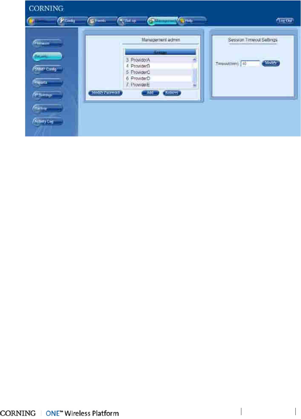
Administration
P/N 709C011801
Page 107
Figure 8-2. Management Tab – Security Menu Option
8.2.1 Defining User Groups
Only the System Administrator defines Groups, where the Groups are defined only by name. After the groups are defined, user
accounts are created where each user is defined within a group. In addition, during the set-up procedure the system modules
(i.e. RIMs) are also associated to defined groups.
The group names comprise of case sensitive, alphanumeric characters (no spaces allowed).
Note the following:
• The group names must comprise of case sensitive, alphanumeric characters (no spaces allowed).
• As each group is defined, a Group Administraor with default authentication is automatically assigned by the system:
User Name - admin (lower case letters)
Password - admin (lower case letters)
Group -
groupname
• Groups along with all their users can be removed (click the Remove button); however, User Accounts cannot be moved to
another group.
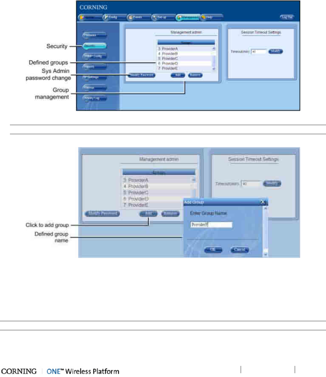
Administration
P/N 709C011801
Page 108
To create a new group
1. Login as System Administrator.
2. Click on the Security option of the Management tab. The Group Management dialog appears, displaying all defined
groups.
Figure 8-3. Group Management Dialog
NOTE: To remove a group, click Remove. The group along with its accounts is removed after a verification prompt.
3. Click Add. The Add Group dialog appears.
Figure 8-4. Add a New Group
4. Enter new group name (enter only alphanumeric characters - no spaces) and click OK. Two operations occur:
• The new group name will be listed.
• The Group Administrator is automatically created with default authentication as previously described).
5. Notify each Group Administrator of his/her login name, password and group name along with a strong recommendation
(requirement) to change the Group Administrator default assigned password (on page 112).
NOTE: Only the Group Admin has access to his/her own password definitions.
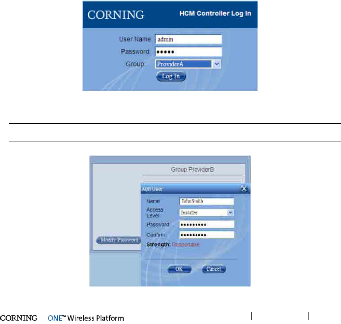
Administration
P/N 709C011801
Page 109
8.2.2 Defining User Accounts
The Group Administrator is assigned default authentication (which should be modified). Each Group Admin can define and
manage the users in his/her group. The Group Administrator does not have access to users from any other Group.
Note the following:
• Each group can support up to 20 Users.
• Each new User is defined by a Name, User Level and Password.
• Users in a group can be of different access levels. The Group Administrator can modify the Passwords of Users in his/her
Group (including their own) and users in the group can modify their own passwords.
• Additional Group Admin level user(s) can be created by a Group Admin and the default Group Admin can be removed.
To add users to a group
1. Log in to the HEU as the Group Admin (default User Name = admin; default Password = admin):
Figure 8-5. Group Admin Login Dialog
2. Click the Security option of the Management tab. The list of defined users for that group will be displayed (empty at
first).
NOTE: If you are currently using the default password, click Modify Password and change the password. (Use the new
password with your next login).
3. Click the Add button. The Add User dialog appears.
Figure 8-6. Adding a User to the Group
4. Enter the User Name - no spaces allowed.
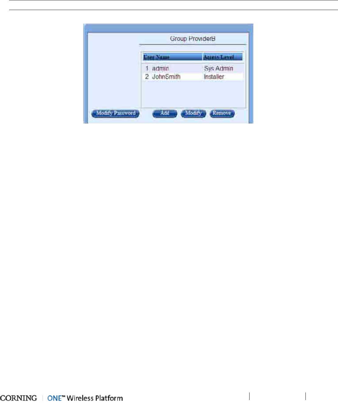
Administration
P/N 709C011801
Page 110
5. Select the Access Level (on page 110). The User can be assigned one of five access levels, where users in a group can
be of different access levels.
6. Assign the Password - it is recommended to use numbers as well as letters. Re-enter the Password to Confirm.
NOTE: Weak passwords will not be accepted. The user may then change his/her own password at any time.
7. Click OK. The new User Account will be added to the Group list.
Figure 8-7. List of Groups
8. You may also:
• Add more Admin Level users to the Group – all will have equal access levels.
• Remove selected users from the list (select and click Remove).
• Modify the selected User Account (select account and click Modify).
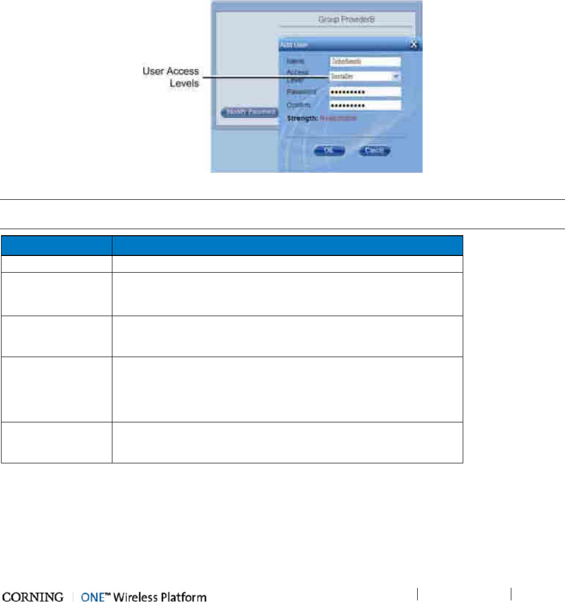
Administration
P/N 709C011801
Page 111
8.2.3 Group Users Access Levels
A Group user can be assigned one of five Access Levels, where users of different access levels can be defined in the same Group.
The HCM supports up to three simultaneous sessions for multiple users (local/remote access). The login of users is enabled
according to priority – when the maximum amount of multiple users are logged in, the HEU terminates the session running for
the lowest level user logged in the longest (user receives alert message and force logout is performed) in order to enable a
higher access level user to login to the system. A message indicating logon denial appears when the maximum number of users
are logged in and a lower level user attempts to log in to the system.
Figure 8-8. Access Levels
NOTE: Any number of users with the same user levels (including Group Administrators) can be created per group, for a
maximum of 20 users per group (up to 500 per system).
Level Description
Operator R/O access to Monitor, Config and Events screens.
Installer R/O Access to Monitor, Config and Events screens.
Write access to
free text parameters
to allow defining location and
identification information.
RF Tech Access to Commissioning Wizard and Monitor, Config and Events screens:
• Write access to all
RF
parameters
• R/O to all other parameters
IT Tech Access to Monitor, Config and Management screens:
• Write access to all
non-RF
parameters
• Access to activity log of all users and groups
• HEU SW upgrade
•
R/O to all other parameters
(Group) Administrator Capabilities:
• All IT Tech capabilities
• Can create and manage users in this group.
Table 8-2.Group Access Level descriptions
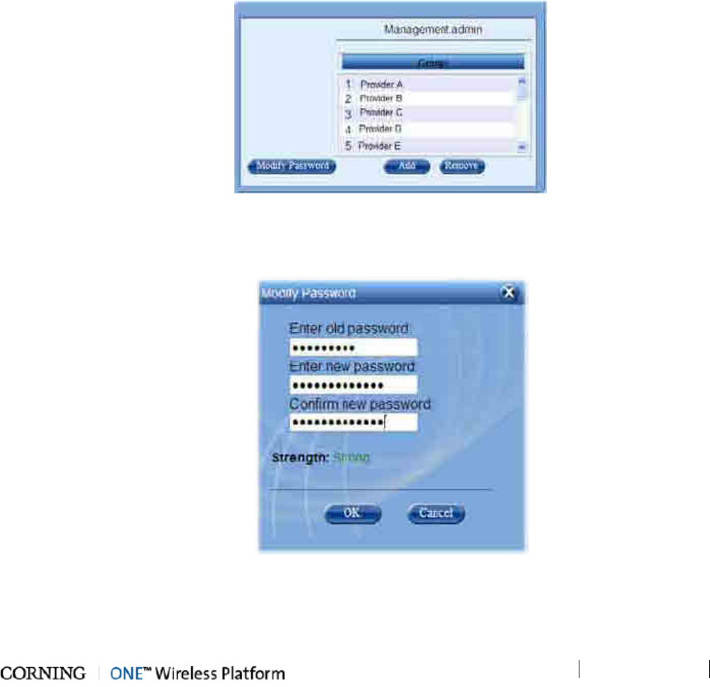
Administration
P/N 709C011801
Page 112
8.2.4 Modifying Passwords
Note the following:
• Each user (including Admin level (on page 112)) can modify his/her own password
• The Group Administrator (on page 112) of each group can reset the passwords of the users in his/her group (does not
require old password)
• User passwords must consist of at least 8 alphanumeric characters (no spaces); however only four asterisks (****) are
displayed.
• HCM management auto-checks the strength of the password and indicates if the password is too weak. Only a "reasonable"
or higher strength level of password will be accepted - passwords indicated as "weak" will not be accepted:
8.2.4.1 System Admin Password Change
To Modify the System Administrator Password
1. Log in to the HCM Management GUI and click on the Security option of the Management tab. The display will slightly
vary depending on your user level. The following figure illustrates the Sys Admin level display.
Figure 8-9. System Admin level Security options display
2. Click the option Modify Password.
3. Enter the Old Password, New Password, confirm the New Password and click OK.
Figure 8-10. Modify (own) Password dialog
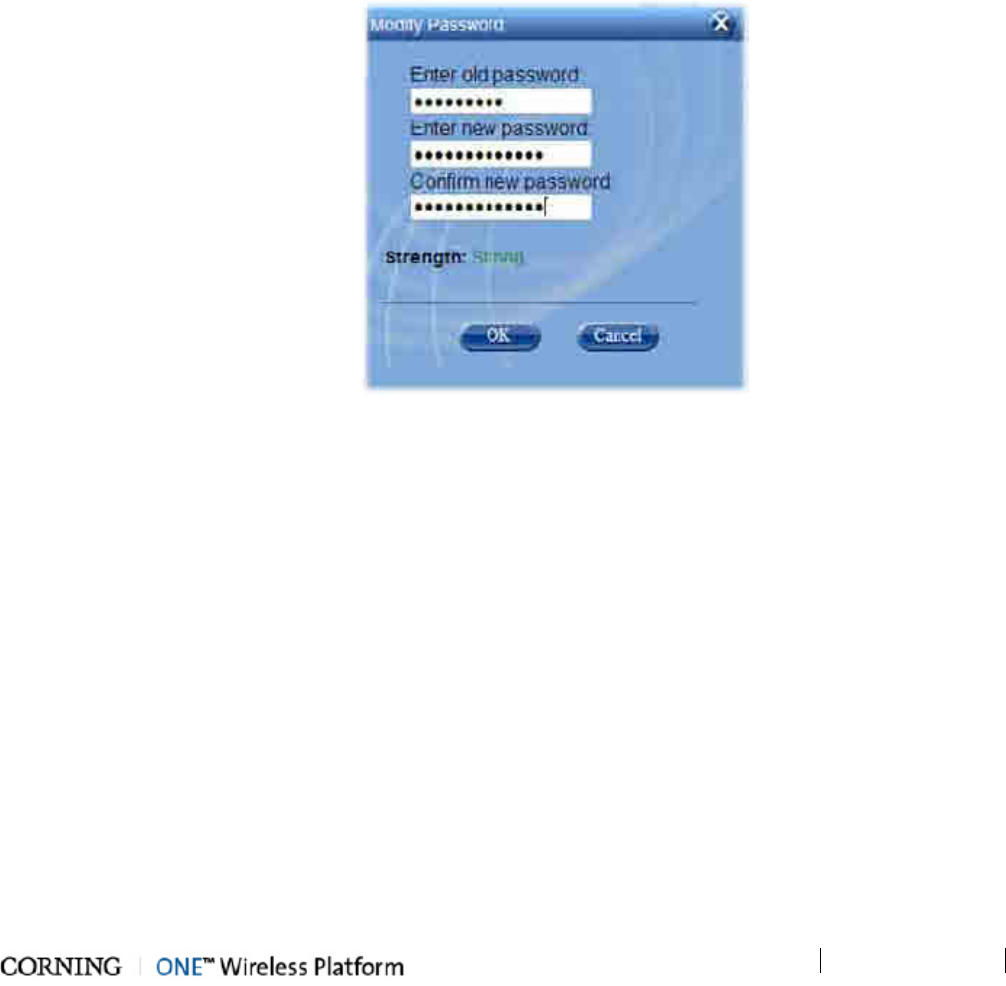
Administration
P/N 709C011801
Page 113
8.2.4.2 Group Admin Password Change
When the System Administrator creates a group, the group is automatically assigned a Group Administrator with default
authentication according to the group name. It is recommended that each Group Administrator change the default
authentication.
This section describes two operations:
• Password change of the Group Admin
• Password change of the User by the Group Admin
To Modify the Group Admin Password
1. Log in to the HCM Management GUI with your Group Admin authentication.
2. Click on the Security option of the Management tab.
3. To change your (Group Admin) password:
• Click Modify Password.
• Enter the Old Password, New Password, confirm the New Password and click OK.
Figure 8-11. Modify (own) Password dialog
4. To modify User information (including password):
• Select the User (can also be the Group Admin) and click Modify.
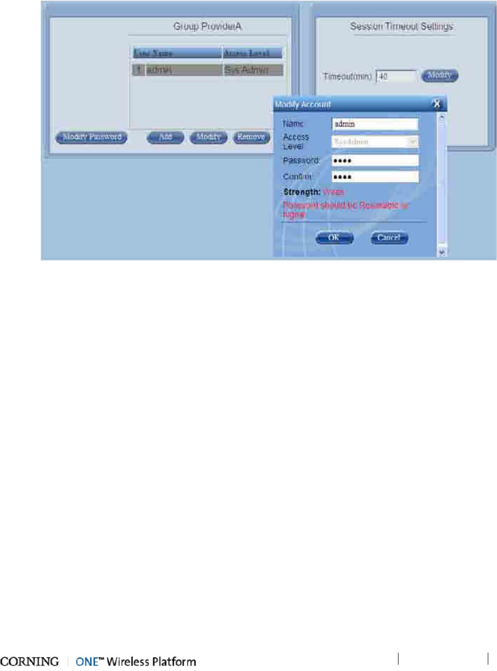
Administration
P/N 709C011801
Page 114
• You may change the User Name and/or Password. Click OK.
Figure 8-12. Modify a User Account dialog
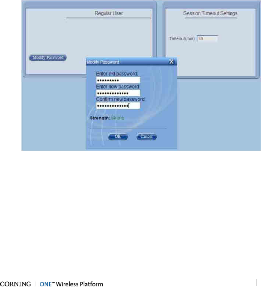
Administration
P/N 709C011801
Page 115
8.2.4.3 User Own Password Change
Each user can modify his/her password. The User password can also be modified by the Group Admin. (on page 112)
User change of own password
1. Log in to the HEU Management GUI with your User authentication.
2. Click on the Security option of the Management tab.
3. To change your password:
• Click Modify Password.
• Enter the Old Password, New Password, confirm the New Password and click OK.
Figure 8-13. User Level Password change
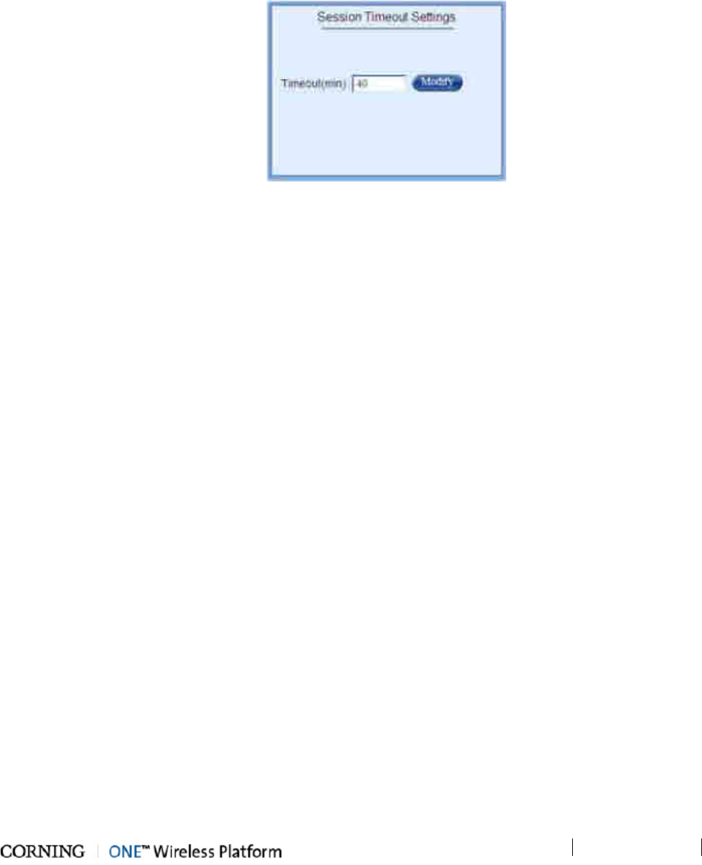
Administration
P/N 709C011801
Page 116
8.2.5 Session Timeout Settings
User session timeout is enforced in the event that no user activity has been detected over a specific time period. The session
timeout period is configurable between 1 min – never.
To configure session timeout period
1. Click the Management tab of the Web GUI and then click the Security menu option.
Figure 8-14. Management Tab – Security Menu Option
2. In the Session Timeout Settings work area, click the Modify button.
3. Enter timeout value between 1 min. and Never.
4. Click OK.
5. Enter timeout value between 1 min. and Never.
6. Click OK.
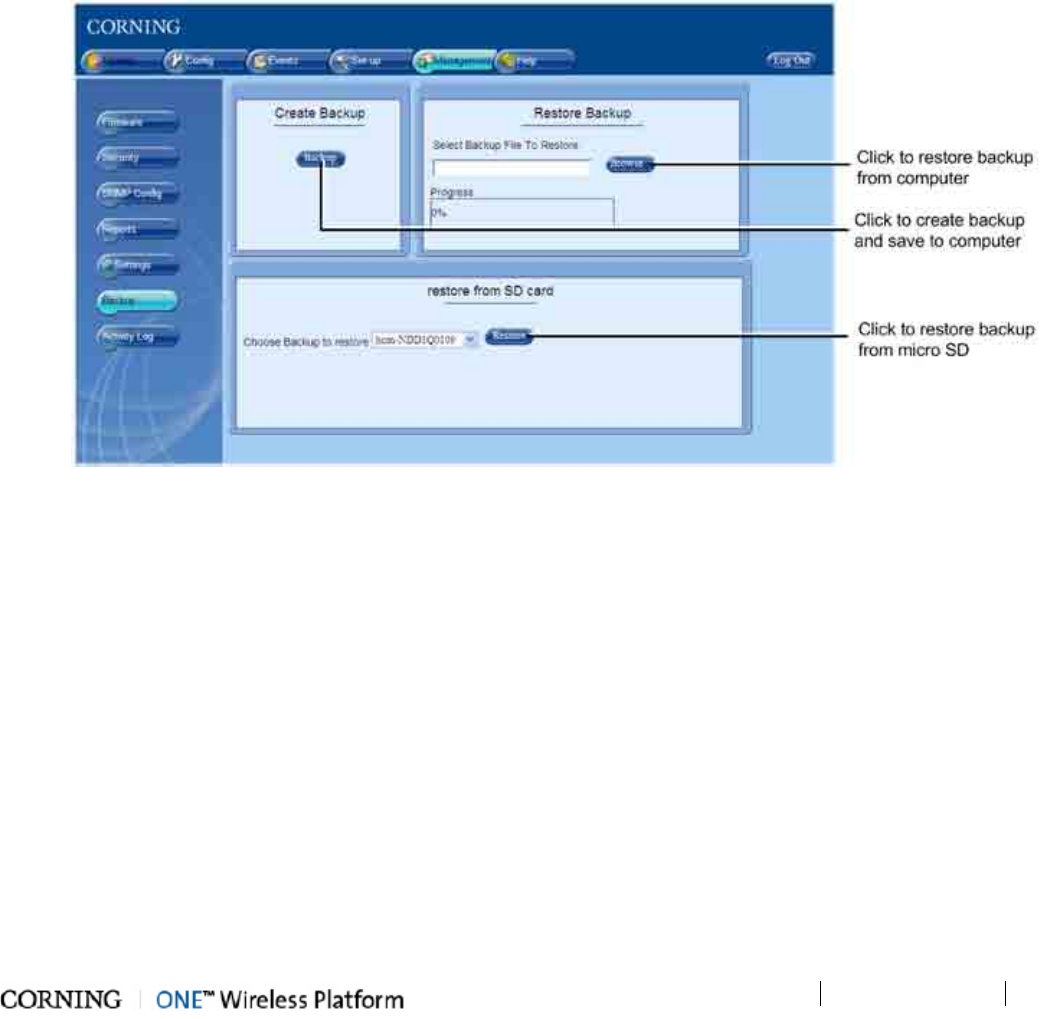
Administration
P/N 709C011801
Page 117
8.3 Backup & Restore Configurations
The management application enables backing up a system configuration, which can later be restored. The configuration file can
be stored on a computer or on a micro SD card inserted in the HCM (see section 2.1.1.1 for SD card slot location). It is
recommended to backup the configuration after each configuration change.
To backup or restore a configuration
1. Click on the Management main menu tab and then click the Backup & Restore sub-menu item.
2. To backup current system configuration - click Backup in the Create Backup area and select a location for the
configuration file.
3. To restore a previously saved configuration:
• From computer - click the Browse button in the Restore Backup area and select a configuration file to restore
• From HCM SD card - select the configuration file from the drop-down list in the Restore from SD Card area and then
click the Restore button
Figure 8-15. Backup & Restore Window
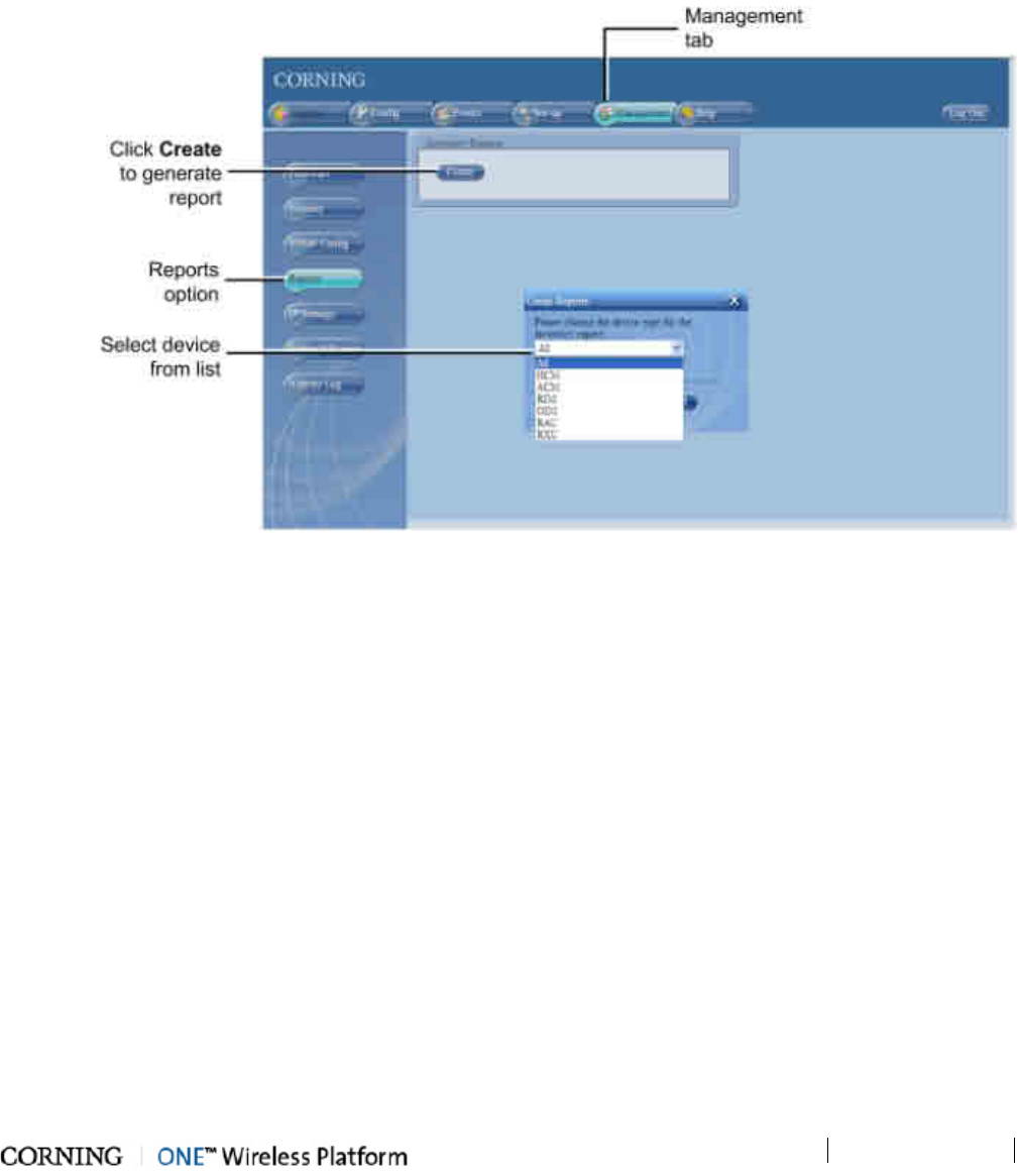
Administration
P/N 709C011801
Page 118
8.4 Generating Device Reports
Inventory reports listing the network elements including module info such as IP and serial number can be generated. The
information displayed in the inventory reports varies according to the type of unit or module.
To Generate a Report
1. Click the Management tab and click the Reports sub-menu.
2. Click the Create button in the Inventory Reports area.
3. Select a device from the drop-down list (or select All reports including all network devices) and click OK.
Figure 8-16. Reports Tab
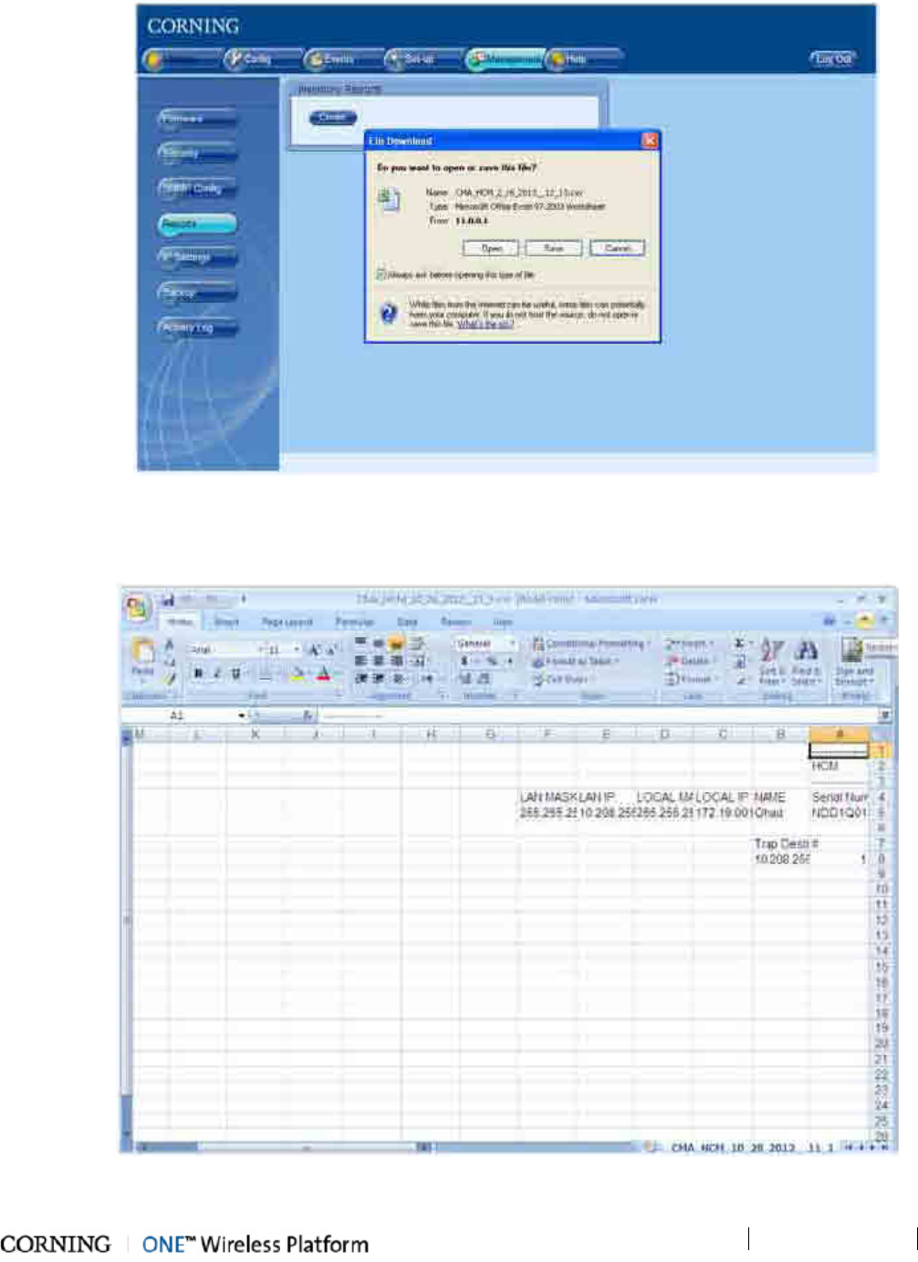
Administration
P/N 709C011801
Page 119
The File Download dialog appears.
Figure 8-17. File Download Dialog
4. Click the Open option to view the report file without saving or Save to save on the generated report on the computer.
5. The inventory report is generated as a .csv file. Example shows report for HCM unit.
Figure 8-18. Example of Generated Inventory report in .CSV File
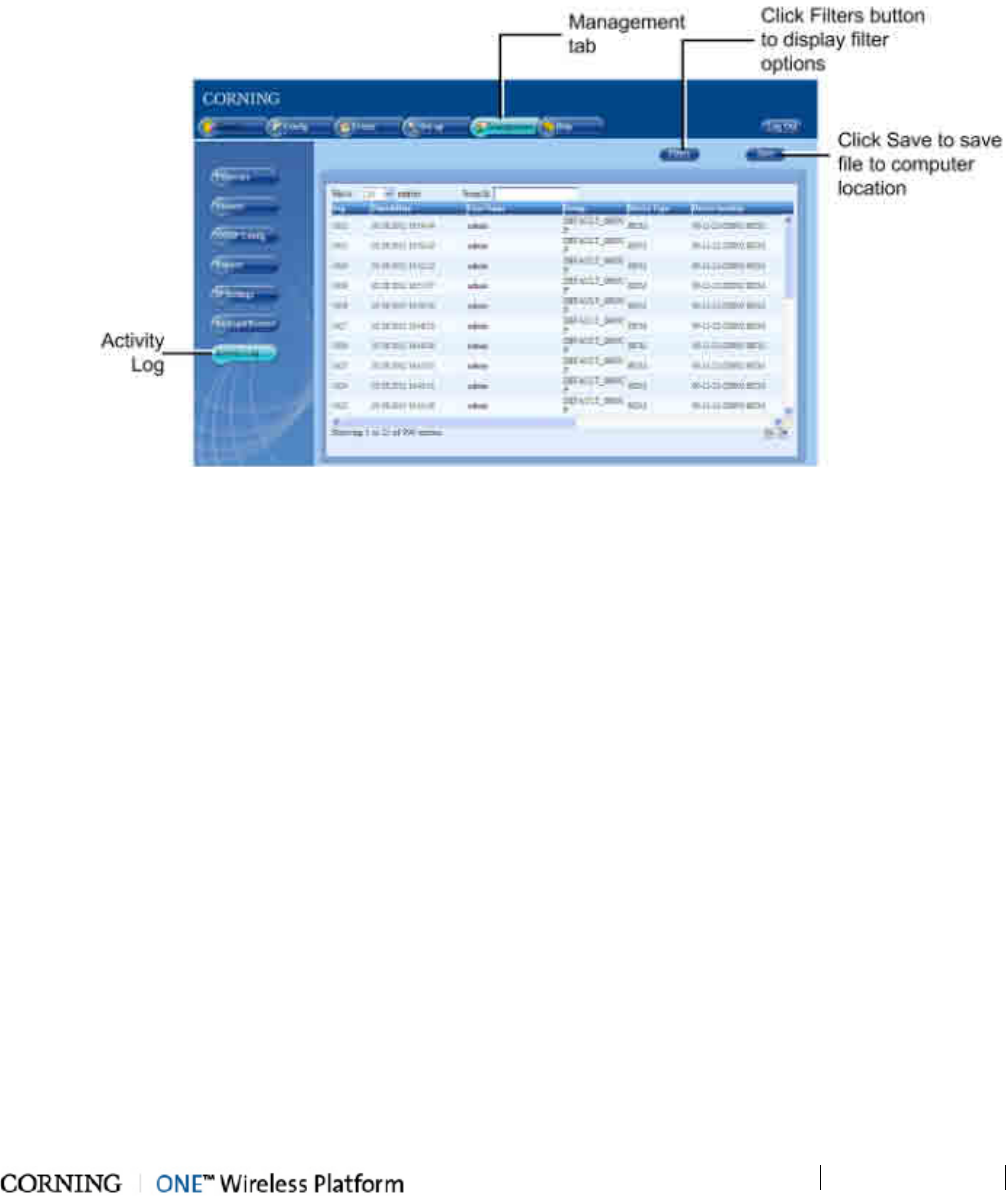
Administration
P/N 709C011801
Page 120
8.5 Activity Log
The Activity Log is used to view activities such as configuration changes, according to a range of criteria such as User, Date,
Device or Activity type. The information can be saved in *.csv format.
To view the activity log
Click on the Management tab and then on the User Activity Log sub-tab. The full log list of all user activities in your group
is displayed.
Figure 8-19. Activity Log Display
Display options:
• Use Show entries to determine the number of displayed events per page.
• Click on a specific header to rearrange activities according to the selected criteria.
• Enter a specific value in Search (i.e. Serial Number, exact Time and Date and so forth) to display a single activity row
• Use Filters to limit the displayed information according to Device Type, Action Type, Date, etc.
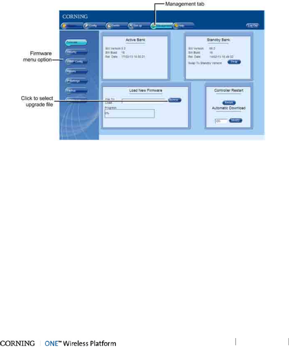
Administration
P/N 709C011801
Page 121
8.6 Firmware Upgrade
The HCM firmware can be upgraded via the web-based GUI. Upgrading the SW requires loading the SW to the Standby Bank,
and swapping the Standby Bank with the Active Bank.
To perform SW upgrade on an HCM installed in the master HEU
1. Open session to HCM (see Opening a Local Session). Click the Management tab and then the Firmware menu option. The
following screen appears.
Figure 8-20. Firmware Upgrade Procedure
2. If necessary, download Bootloader for upgrade procedure as follows:
• In the Load New Firmware area, click the Browse button and select the SW upgrade Bootloader file: boo HCM vX.btl
• Click the Load button (appears after file is selected) to load the selected upgrade file on to the HCM.
• Download progress appears in Progress bar. Click OK when “Download is Complete message” appears (see following
figure).
3. Download the new SW for upgrade procedure as follows:
• In the Load new Firmware area, click the browse button and select SW upgrade img file: HCM VerX.img
• Click the Load button
• Download progress appears in Progress bar. Click OK when Download is Complete message appears
4. After the SW download (in previous step) is complete, perform SW upgrade on the HCM as follows:
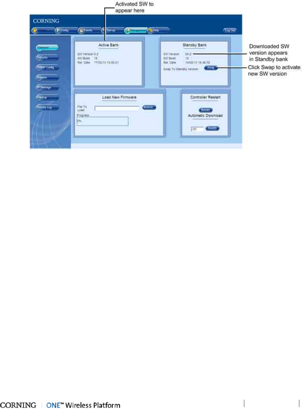
Administration
P/N 709C011801
Page 122
• Downloaded SW version appears in Standby Bank.
Figure 8-21. Management-Firmware Screen
5. Click the Swap button. The Swap and Restart prompt appears.
• Click OK.
• Downloaded SW version appears in Active Bank area and HCM is automatically restarted.
6. Log out of the system when procedure is complete.
7. Repeat Step 1 (login) and Step 4 (download new SW) - the SW Download procedure is repeated so that the new SW
appears in both the Active Bank and the Standby Bank.
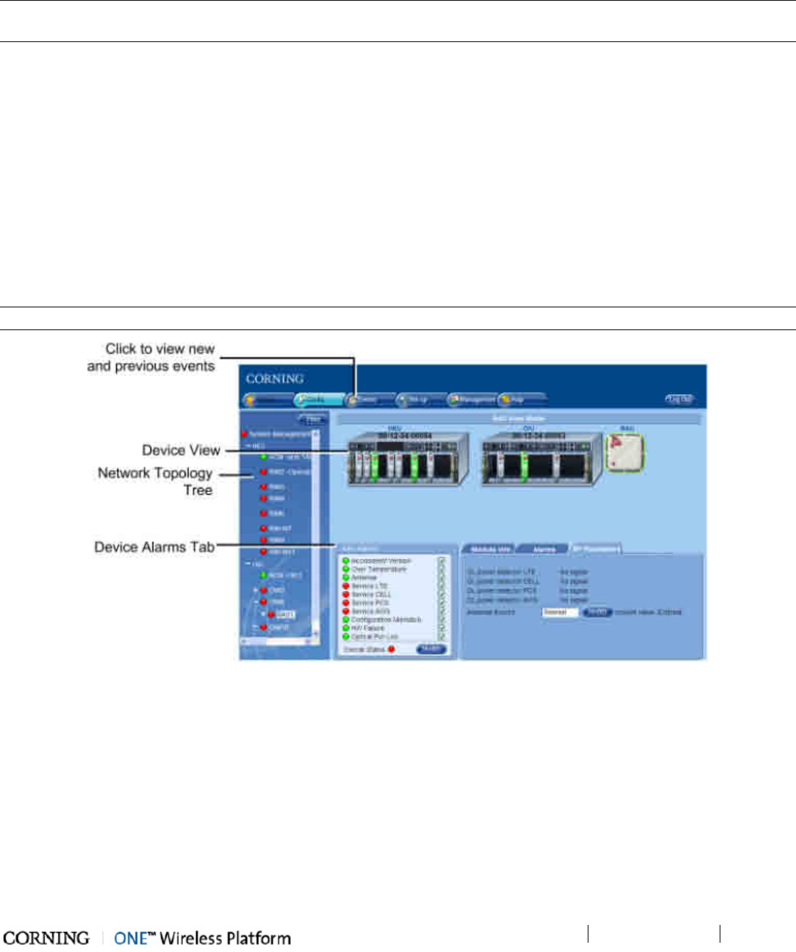
Monitoring and Troubleshooting
P/N 709C011801
Page 123
9 Monitoring and Troubleshooting
IMPORTANT: The available tabs and options in the System Management Web GUI may vary depending on the access level used
to open your session.
9.1 Overview
The Web Management Application provides several tools for monitoring and troubleshooting the site. The tools are available in
the Config and in the Events tabs.
The tools include:
• Network topology tree (on page 123) - provides general view of system status and status of each device (Config tab).
• Device view (on page 125) - fault sourcing at a glance. Device specific view showing the module and main LEDs (Config
tab)
• Device specific alarms (on page 125) - provide detailed information on device alarm viewed in the Topology Tree (Config
tab)
• Display of events (on page 133) - show device fault (trap) notifications such as low power, disconnect, etc.
NOTE: Configuration changes can be viewed in the Activity Log (on page 120).
Figure 9-1. Overview of Fault Sourcing Tools
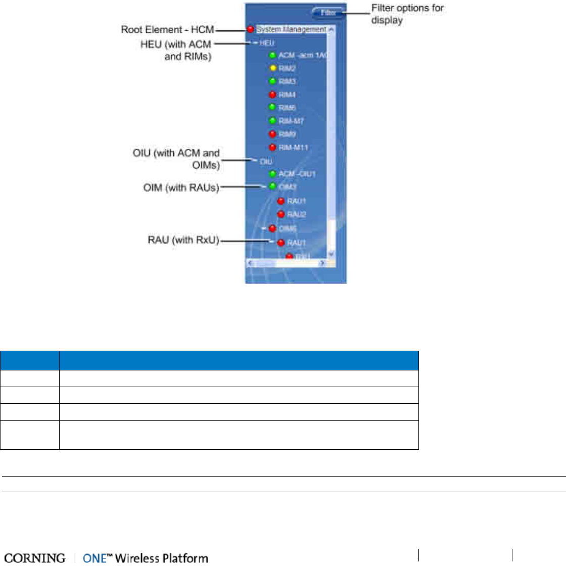
Monitoring and Troubleshooting
P/N 709C011801
Page 124
9.2 Network Topology Tree - Fault Sourcing
The Web GUI Management application Network Topology Tree is viewed in the Config main menu tab. The Network Topology
tree shows the elements of the HCM controller to which the session was opened, and the hosted devices. The connected network
devices are automatically detected in the baseline and displayed in the Network Topology Tree in the hierarchy in which they are
connected.
The Network Topology tree includes problem sourcing features such as:
• Color indication corresponding to the elements status
• Real-time updates of device status
• Upward propagated element status colors
Figure 9-2. Example of Network Topology Tree
Each device element in the network topology is displayed along with adjacent LED corresponding to their status. Faults are
propagated only through an arrow so that the faulty device can be quickly identified by its color. The tree colors indicate the
status of the elements.
Color Indicates
Green OK
Yellow Minor Error
Red Major Error
Gray No communication to a device set in Base-
Line. To remove from baseline, click
the Baseline Reset button in the System Management (HCM) Module Info tab.
Table 9-1. Tree Color Code Descriptions
NOTE: If communication to a device that was not set in Base-Line is lost, the device disappears from the display.
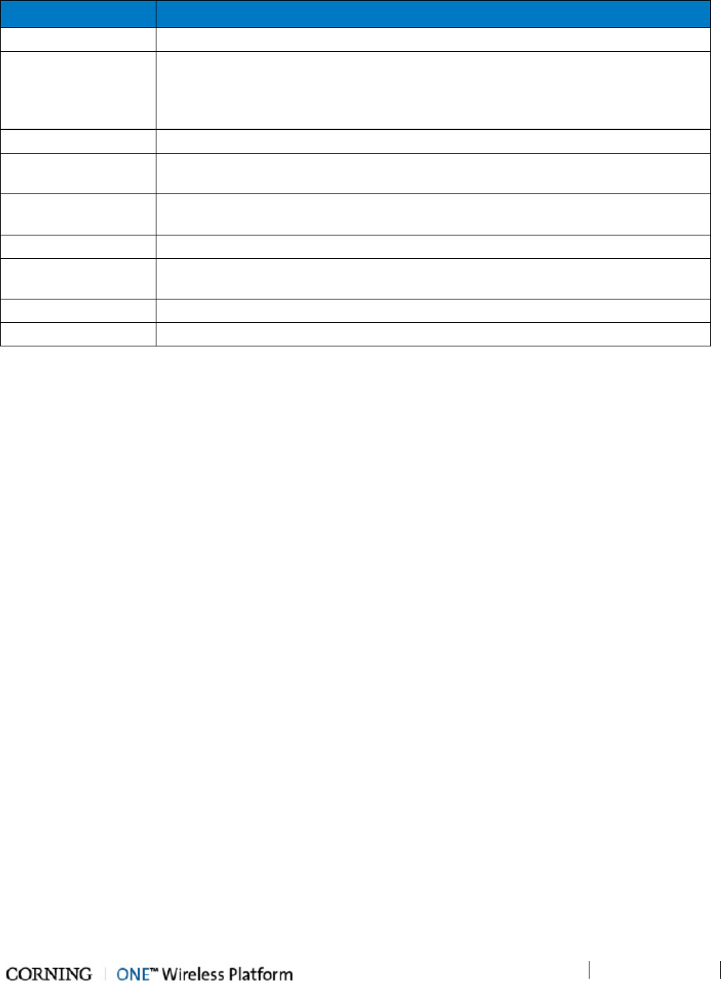
Monitoring and Troubleshooting
P/N 709C011801
Page 125
The ONE system element devices are displayed as follows:
Item in Tree Description
System Management Root item, represents the HCM controller (physically installed in the HEU)
HEU
Headend Unit hosting corresponding modules (ACM, RIM).
NOTE: The HCM controller module is physically installed in the HEU chassis, however in
terms of management is divided into two elements (HCM - System Management and
ACM).
ACM Auxiliary Control Module (both HEU and OIU units host this module)
RIM RIM modules displayed under host HEU with the number of the slot in which it is
installed (e.g. RIM2)
RIM-M RIM MIMO modules displayed under host HEU with the number of the slot in which it is
installed (e.g. RIM-M2)
OIU Optical Interface Unit with corresponding modules (ACM, RAU)
OIM Optical Interface Module under host OIU with the number of the slot in which it is
installed (e.g. OIM3)
RAU RF Antenna Unit. Each RAU is displayed under the host OIM.
RxU RF Expansion Unit. Each RxU is displayed under the host RAU.
Table 9-2. System devices Displayed in Network Topology tree
Quickly Finding the Faulty Unit
The color of each unit (except the System Management element - HCM) depends on its local status and on the status of its'
hosted units. The System management element (HCM) will always be colored by the severest color of any of the units under it
or due to its local inputs (or operation). Units name in the tree will consist of the unit type description followed by the user free
text (defined via Module Info tab): e.g. RIM2-"Operator 1 - CELL". The unit’s relative connection (port and slot) will continue
to appear in the elements private window on the top bar
Once the setup and adjustment procedures have been completed successfully for all of the system elements the adjustment
procedures all devices should be displayed in green in the Network Topology tree. In addition, the Event display can be used
to verify that no
new
events are received and that the system is stable.
If fault notifications are received (events) or devices are displayed in red or yellow colors in the Network Topology tree, the
Alarms tab of the relevant devices can be used to source the problem.
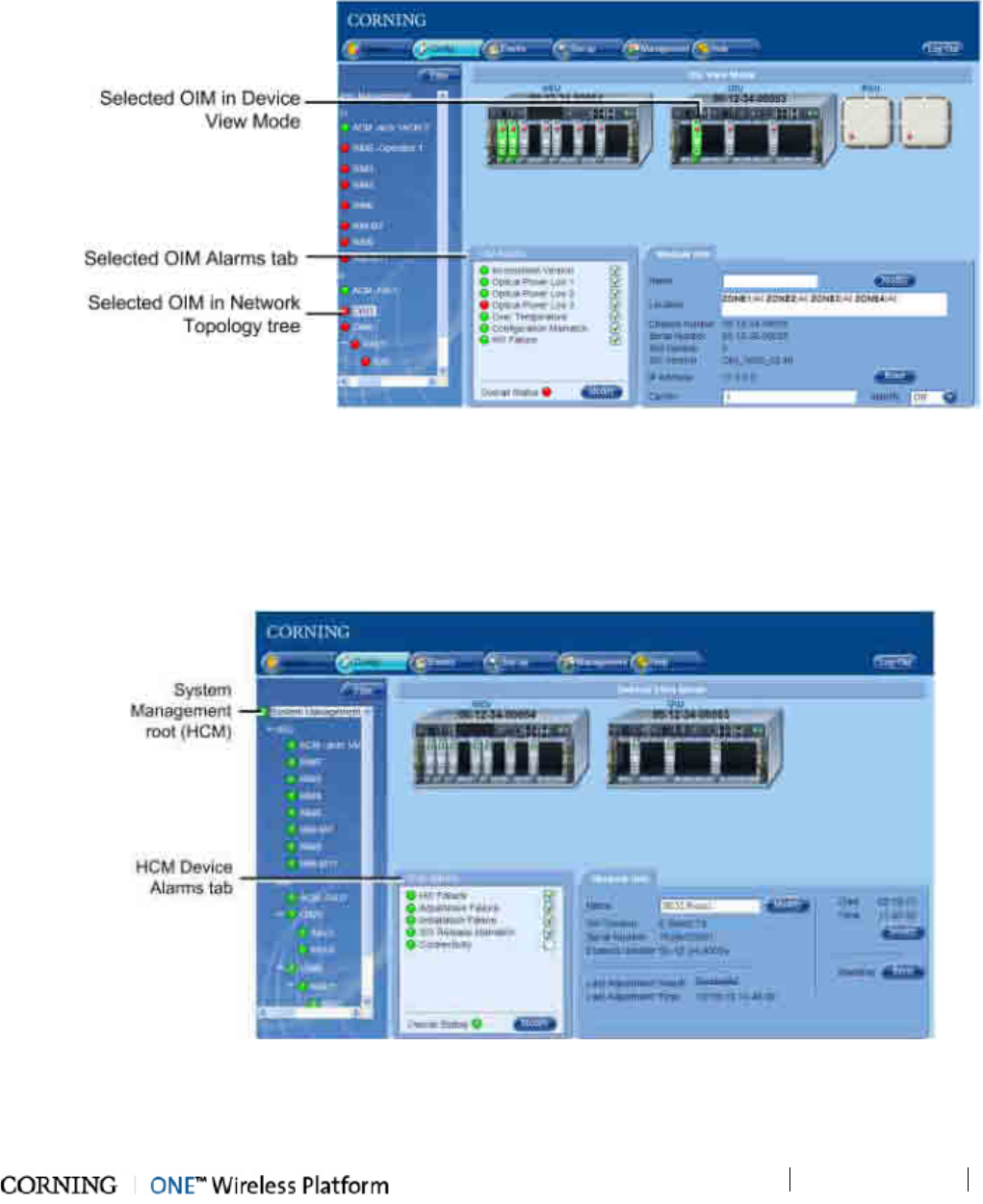
Monitoring and Troubleshooting
P/N 709C011801
Page 126
9.3 Fault Sourcing through the Device View and Alarms Tab
When an item in the Network Topology Tree is clicked, an icon representative of the device view appears along with the
configuration and Alarms tabs. The LED indicator on each module in the device view represents the overall status of the module
which corresponds to the Overall Status alarm in the Alarms tab and the LED in the Network Topology. The administrator can
then assess the display at a glance and further analyze the situation via the device Alarms tab displayed for each module.
Figure 9-3. Example of Selected Device in Network Topology and Device View
9.3.1 HCM (System Management) Device View and Alarms
The HCM (System Management root item) is the only network element for which a device view is not displayed. The Alarms tab
displays the HCM alarms.
Figure 9-4. HCM Device Alarms
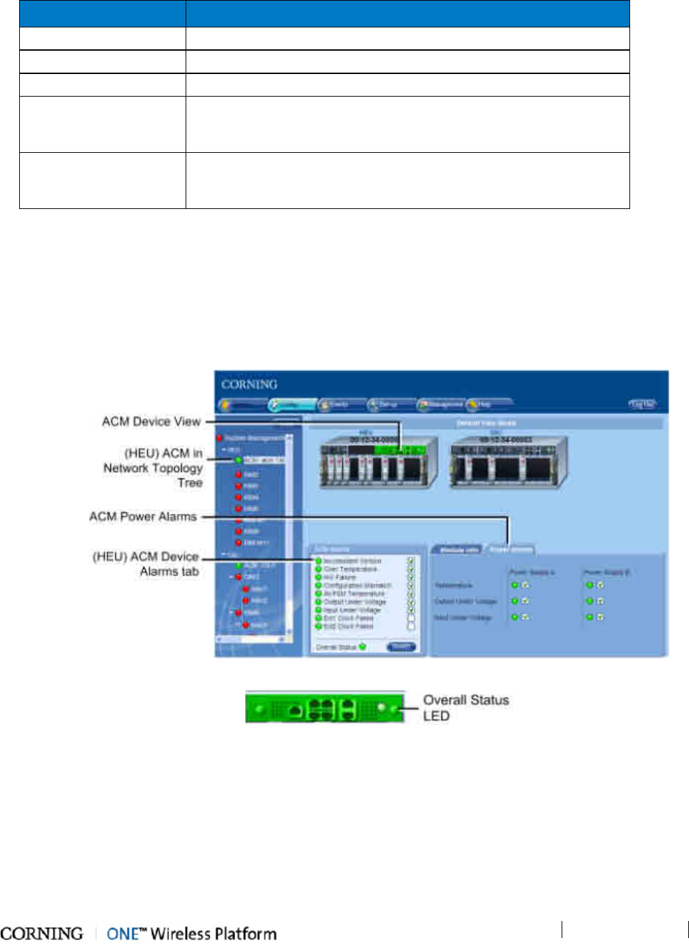
Monitoring and Troubleshooting
P/N 709C011801
Page 127
Alarm Name
Description
HW Failure Indicates HCM faulty HW
Adjustment Failure Indicates unsuccessful adjustment procedure
Installation Failure Indicates faulty physical installation in one of the modules
SW Release Mismatch Indicates that a module (or modules) in the system does not have the
defined active release; several modules may not have corresponding
SW versions; severity – minor
Connectivity Indicates faulty connectivity state in one of the in one of the previously
discovered (baseline) system modules. Module should appear grey in
the Network Topology and the Device View Mode.
Table 9-3. HCM Alarms Descriptions
9.3.2 ACM Device Alarms and View
The device alarms and view for the ACM module are similar for both HEU and OIU chassis. The ACM Device view and Alarms are
viewed by clicking on the ACM item (under the host HEU or OIU) in the Network Topology. The ACM monitors the PSM alarms,
where the alarms for each PSM can be viewed via the Power Alarms tab.
Figure 9-5. (HEU) ACM Device View and Alarms
Figure 9-6. ACM Device View and Overall Status LED
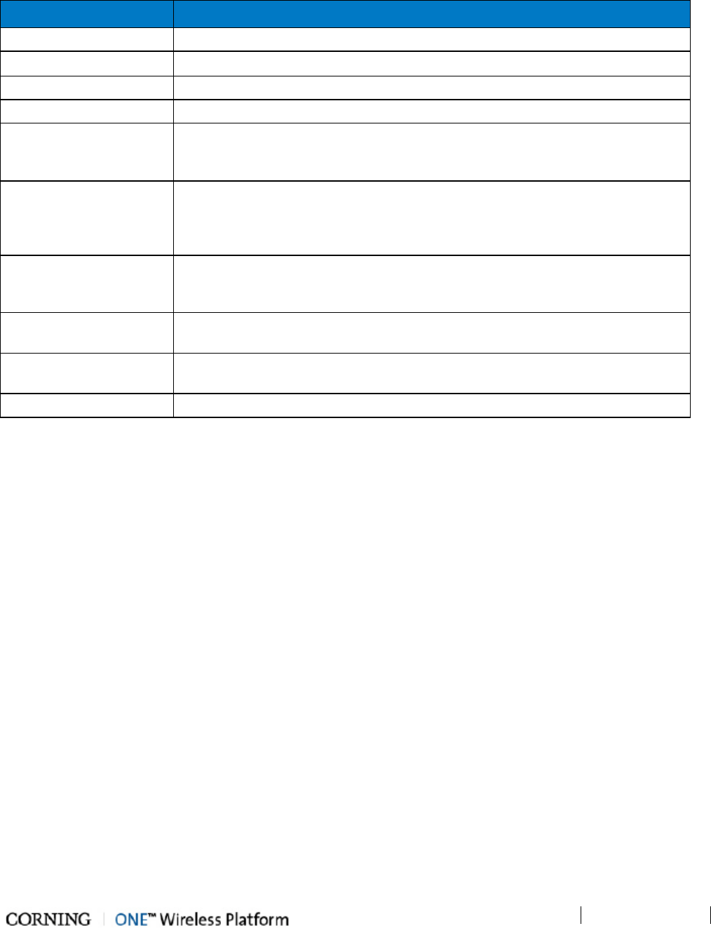
Monitoring and Troubleshooting
P/N 709C011801
Page 128
The following table provides the descriptions for the ACM Alarms. Alarms that are specific for the HEU or the OIU ACM module
are indicated as such.
Device Alarm Description
Inconsistent Versions Indicates that the module does not have the defined active release
Over Temperature Ambient temperature inside the ACM is > 75
◦
C
HW Failure Indicates ACM faulty HW upon initialization or during operation
Configuration Mismatch Unsuccessful adjustment procedure for the selected module
All PSM Temperature Indicates that the temperature of either one (Severity – minor) or both (Severity –
Major) of the PSM modules is > + 100°C. Refer to Power Alarms to check which
PSM module has generated the alarm.
Output Under Voltage Indicates that the ACM has detected an input voltage value < 10.8V DC from either
one of the PSM modules (Severity – minor) or both (Severity – Critical) during 3
consequent samplings. Refer to Power Alarms to check which PSM module has
generated the alarm
Input Under Voltage Indicates that the ACM has detected an input voltage value of < 60V AC from
either one PSM module (Severity – minor) /both PSM modules (Severity – Critical).
Refer to Power Alarms to check which PSM module has generated the alarm.
(HEU-ACM) Ext1/Ext2
Clock Failed
Indicates failure in master reference clock
(OIU-ACM) Pilot Clock
Failed
Indicates failure in reference in the pilot clock in the OIU Expander
Overall Status Overall status of enabled (unmasked) alarms
Table 9-4. ACM Power Alarms Descriptions
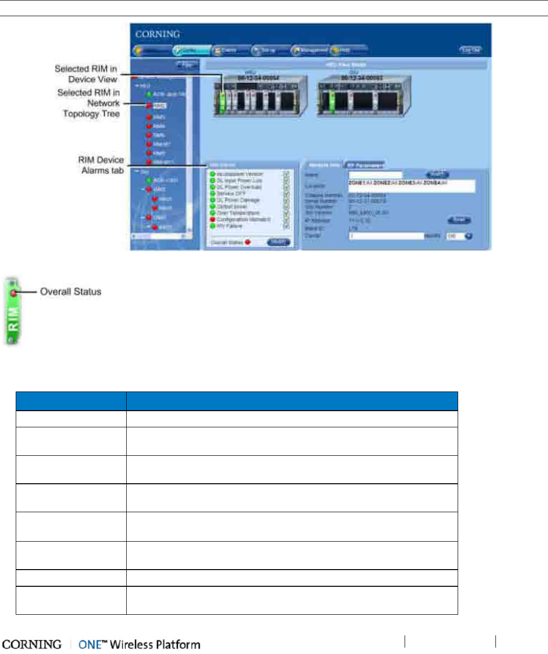
Monitoring and Troubleshooting
P/N 709C011801
Page 129
9.3.3 RIM Module Device View and Alarms
Click on the RIM module in the Network Topology to display the RIM device Alarms and the module device view.
NOTE: When the RIM is selected, the RIM module and the associated OIM module appear green in the Device View Mode.
Figure 9-7. RIM Device View and Alarms
Figure 9-8.
RIM Device View Icon
The following table provides the descriptions for the RIM Device Alarms tab.
Device Alarm
Description
Inconsistent Versions Indicates that the module does not have the defined active release
DL Input Power Low Red (major fault): BTS RF power input to the RIM is at least 15 dB lower
than the configured max. expected power
DL Power Overload Red (major fault): BTS RF power input to the RIM is at least 3 dB higher
than the value measured during the adjustment procedure.
Service OFF Indicates that service has been disabled by the user; Severity – minor
(yellow)
DL Power Damage Indicates that the input RF power level ≥ 43 dB; Severity – minor
(yellow).
In this case the over power protection mechanism is enabled.
Output power
Indicates that the detected power is 20 dBm or more below the configured
output power level
Over Temperature Ambient temperature inside the RIM is > 75
Configuration
Mismatch
Unsuccessful adjustment procedure for the selected module
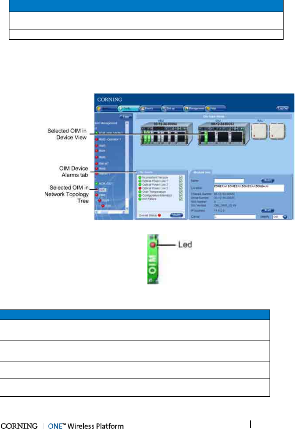
Monitoring and Troubleshooting
P/N 709C011801
Page 130
Device Alarm
Description
HW Failure Indicates HW problem during startup or during normal operation; Alarm
severity – minor (yellow)
Overall Status Indicates overall status of enabled (unmasked) alarms
Table 9-5. RIM Device Alarms Descriptions
9.3.4 OIM Device View and Alarms
Click on the OIM hosted by the OIU module in the Network Topology to display the OIM module Alarms tab and the module
device view. When the OIM is selected, the corresponding RIM(s) in the RF path are also indicated (appears green).
Figure 9-9.
OIM Alarms Tab and Device View
Figure 9-10. OIM Device View and Overall Status LED
The following table provides the descriptions for the OIM Alarms tab.
Device Alarm
Description
Inconsistent Version Indicates that the module does not have the defined active release
Optical Power LOW 1/2/3 Red – indicates optical link power (PDI) is < 3dBm
Over Temperature Indicates that the ambient temperature in the OIM is
≥
75
◦
C
Configuration Mismatch Unsuccessful adjustment procedure for the selected module
HW Failure Indicates HW problem during startup or during normal operation;
Severity – minor (yellow)
Overall Status Overall status of enabled (unmasked) alarms. Reflects the maximum
severity of the device alarms.
Table 9-6. OIM Device Alarms Descriptions
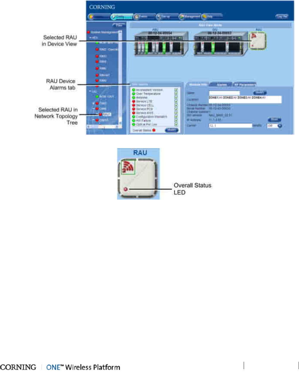
Monitoring and Troubleshooting
P/N 709C011801
Page 131
9.3.5 RAU Device View and Alarms
Click on the RAU hosted under the hosted OIM module in the Network Topology to display the RAU Alarms tab and the module
device view. When the RAU is selected, the corresponding OIM and RIM modules in the RF path are also indicated (appear
green).
Figure 9-11. RAU Alarms Tab and Device View Mode
Figure 9-12. RAU Device View and Overall Status LED
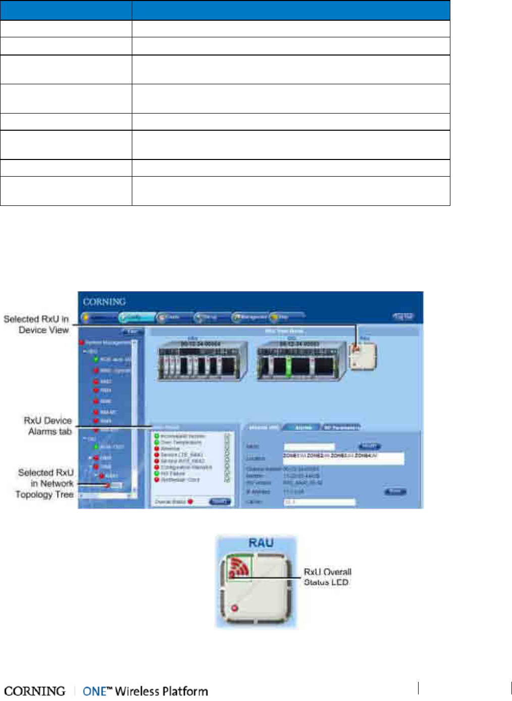
Monitoring and Troubleshooting
P/N 709C011801
Page 132
The following table provides the descriptions for the RAU Device Alarms tab.
Device Alarm
Description
Inconsistent Version Indicates that the module does not have the defined active release
Over Temperature Indicates that the ambient temperature in the OIM is
≥
75°
◦
C
Antenna Indicates faulty antenna connectivity –
external antenna not detected;
Severity – major (red)
Service
LTE/CELL/PCS/AWS
Indicates that service has been disabled by user
Configuration Mismatch Unsuccessful adjustment procedure for the selected module
HW Failure Indicates HW problem during startup or during normal operation;
Severity – minor (yellow)
Optical Pwr Low Red – indicates optical link power (PDI) is < 3dBm
Overall Status Overall status of enabled (unmasked) alarms. Reflects the maximum
severity of the device alarms.
Table 9-7. RAU Device Alarms Descriptions
9.3.6 RxU View
Click on the RxU under the hosted RAU module in the Network Topology to display the RxU Alarms tab and the module device
view. Note that the RxU device view is in the RAU icon.
Figure 9-13. RxU Alarms Tab and Device View
Figure 9-14. RxU Device View and Overall Status LED
The following table provides the descriptions for the RxU Device Alarms tab.
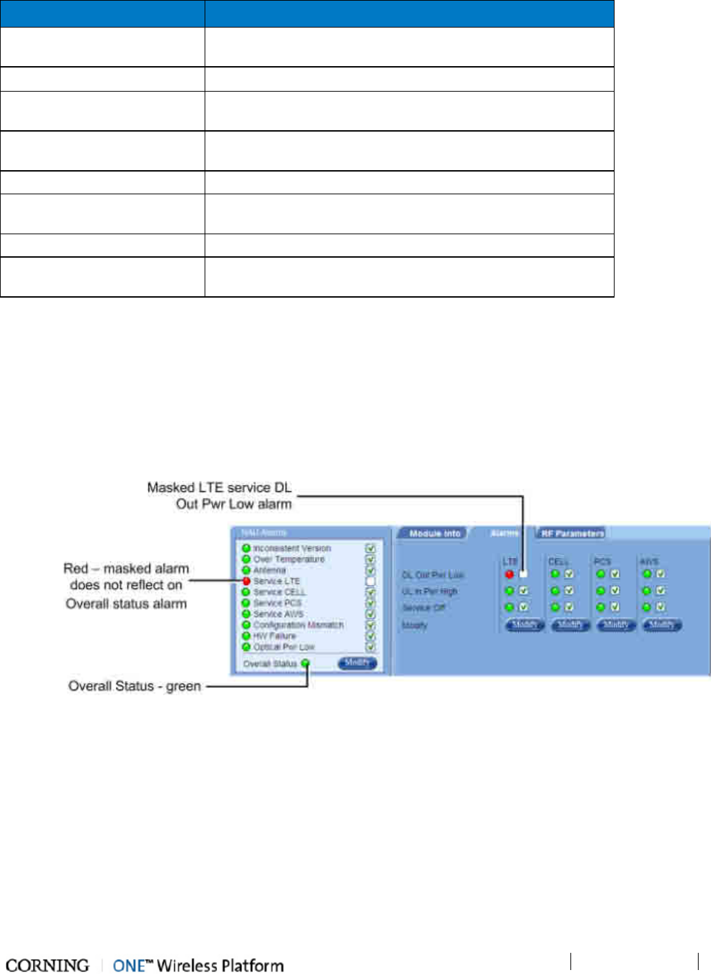
Monitoring and Troubleshooting
P/N 709C011801
Page 133
Device Alarm Description
Inconsistent Version Indicates that the module does not have the defined active
release
Over Temperature Indicates that the ambient temperature in the OIM is
≥
75
◦
C
Antenna Indicates faulty antenna connectivity –external antenna not
detected; Severity – major (red)
Service
LTE_MIMO/AWS_MIMO
Service disabled by user
Configuration Mismatch Unsuccessful adjustment procedure for the selected module
HW Failure Indicates HW problem during startup or during normal operation;
Severity – minor (yellow)
Synthesizer Clock Indicates locked synthesizer clock; Severity – major (red)
Overall Status Overall status of enabled (unmasked) alarms. Reflects the
maximum severity of the device alarms.
Table 9-8. RxU Device Alarms Descriptions
9.4 Masking Irrelevant Alarms
Irrelevant alarms can be masked (disabled) so that they do not affect the overall status of the device alarms. Masking an alarm
suppresses it.
In the example below, the RAU Alarms dialog shows the alarm response if the DL Out Pwr Low alarm is masked (disabled). In
that case the Service LTE will be red but the Overall Status will be green.
Figure 9-15. Example of Masked RAU Alarm
To Mask Irrelevant Alarms
1. Select the device in the network topology tree (See section Network Topology).
2. Click the Alarms tab Modify button.
3. Uncheck the alarm to be masked.
4. Click OK to apply.
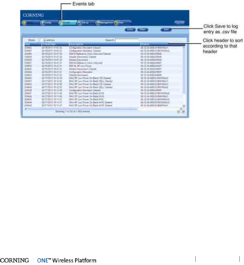
Monitoring and Troubleshooting
P/N 709C011801
Page 134
9.5 Events Display
The event display is automatically updated with every change in the status of any of the system elements. By default, up to 1,000
reported events can be displayed. Use the scroll bar on the right to scroll through the displayed events.
Only events occurring on the network ports or the device are displayed: configuration changes that are initiated by the network
manager are not considered events.
The viewed events may be acknowledged and filtered according to various user defined criteria.
To View the Events Log
Click on the main menu Events tab. The Event window appears. Each notification consists of a unique sequence number, event
date and time stamp, description and device generating the event and the event severity.
Figure 9-16. Events Tab
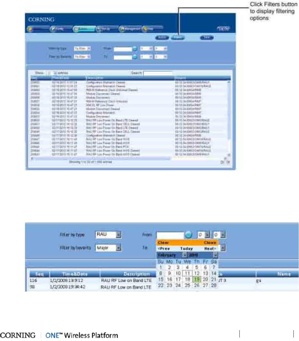
Monitoring and Troubleshooting
P/N 709C011801
Page 135
9.5.1 Filtering Displayed Events
You may filter the displayed events according to various criteria such as device source, event level (major, minor, etc.), event
date, etc.
To Filter the Displayed Events:
1. In the Events window, click the Filters button.
Figure 9-17. Events - Filtering Options
2. To display only events from one type of device, choose the device in Filter by Type field: RIM, OIM, RAU, etc.
3. To display only events from a specific severity level and up, choose the minimum level in the Filter by Severity field. For
example, choosing Notify will display all severity levels; choosing Minor will display Minor and Major levels only.
• To display only events initiated within a limited range of time:
Figure 9-18. Defining date Range for Events Display
• Browse to display the appropriate months and click on the days to determine the range of time for the displayed events.

Monitoring and
Troubleshooting
P/N 709C011801
Page 136
• You may also enter specific hours and minutes to further limit the range of time:
Figure 9-19. Defining Time Range for Events Display
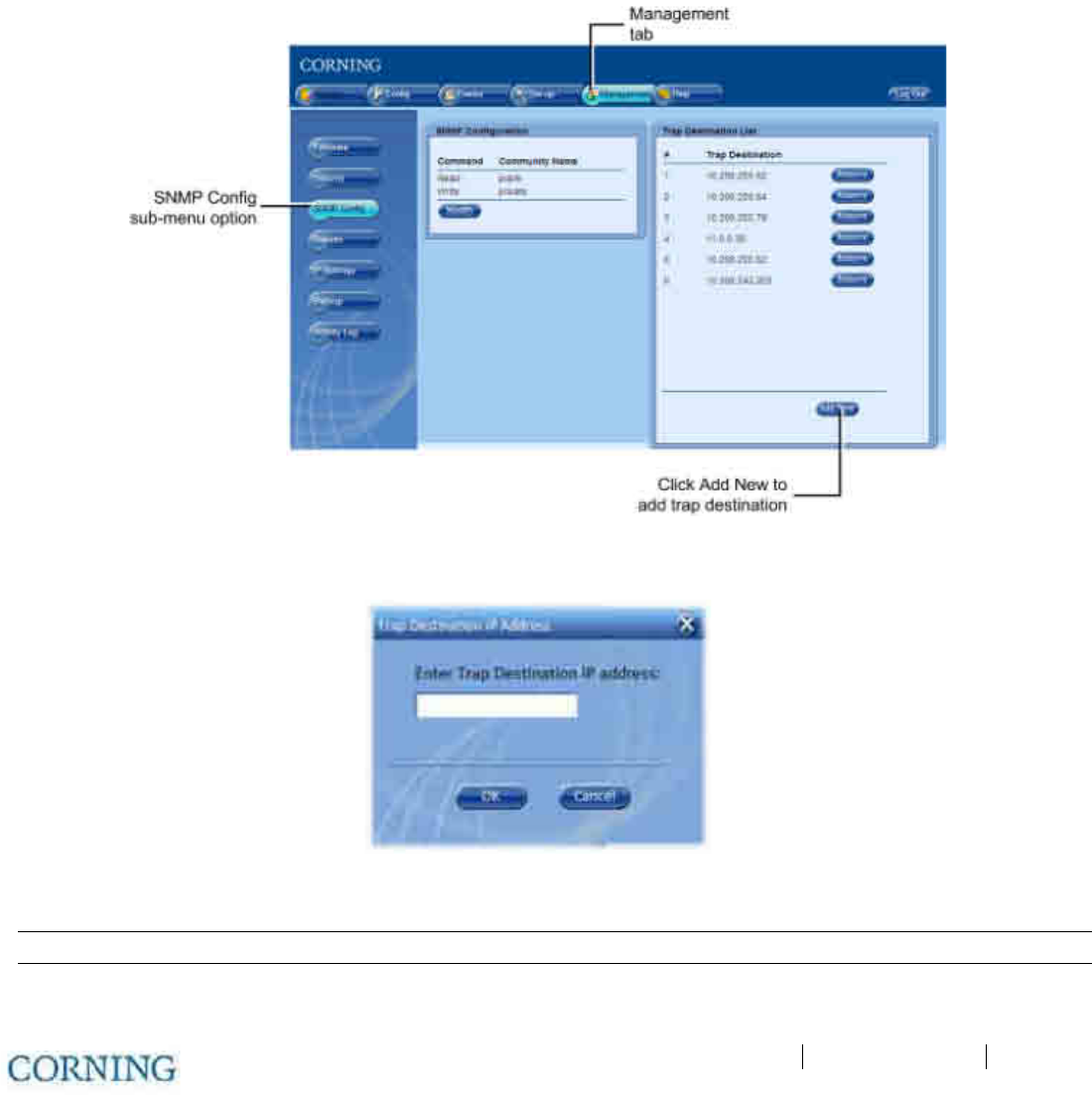
SNMP Management P/N 709C011801 Page 137
10 SNMP Management
The SNMP Management is performed using any standard SNMP Manager.
10.1 SNMP Destination Address Configuration
Use this option to define the IP addresses to which SNMP traps will be sent. The IP addresses are defined per domain and are
relevant to all the HCM controller modules assigned to that domain. Up to 10 IP addresses can be defined per domain.
To Define the Destination IP Addresses
1. Click the main menu Management tab and select SNMP Config (side bar) menu option. The following pane appears.
Figure 10-1. SNMP Config Tab
2. Click Add New button in Trap Destination List area. The Trap Destination IP Address dialog appears.
Figure 10-2. Trap Destination IP Address Dialog
3. Enter the IP address and click OK. The IP address will be added to the list.
NOTE: To remove the IP address, click the Remove button adjacent to the IP address in the displayed list.
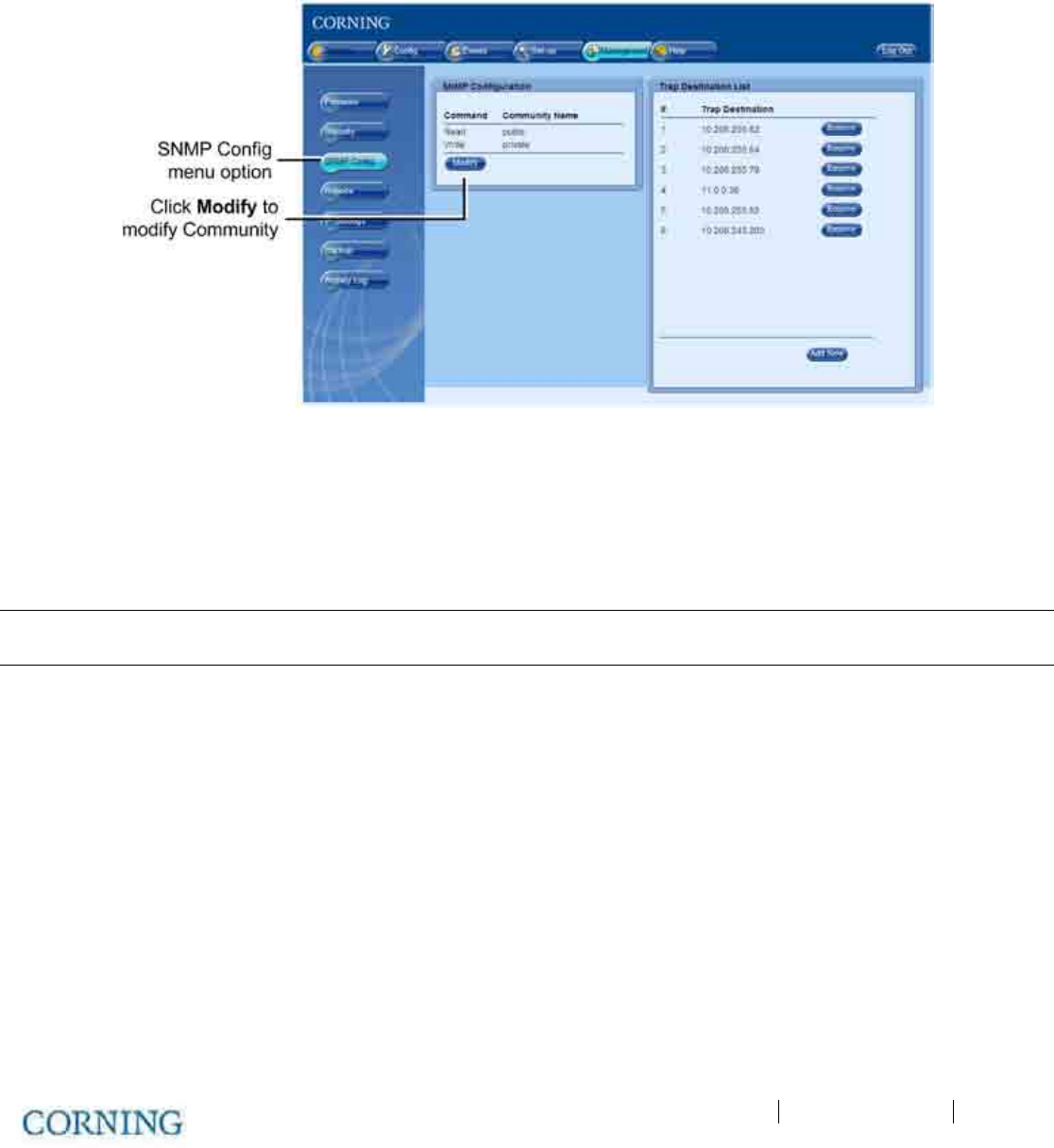
SNMP Management P/N 709C011801 Page 138
10.2 Modifying the Read/Write Community Parameters
Use this option to modify the Read/Write Community Name of the HCM.
To Modify the Read/Write Community Name
1. Click the Management in the menu bar and select SNMP Config in the side bar. The Management pane appears.
2. In the SNMP Configuration area, click Modify.
Figure 10-3. Management-SNMP Config Screen
3. Define the new Read and Write values and click OK.
10.3 SNMP Management using any Third Party SNMP Manager
The MIBs provide information regarding the managed system and general indication of system failure.
NOTE: The Web GUI management application provides a graphical view of the managed network topology, a graphical view of
the managed element parameters and enables identifying the source of the problem at a glance.
The HCM includes several MIB files that enable viewing traps sent by the controller and to configure and monitor the managed
Corning ONE™ system through any third party SNMP manager (such as HP OpenView, CA Unicenter, IBM Tivoli, Castelrock
SNMPc).
Types of MIBs provided:
• MIB-II system group parameters group (RFC-1213) – A standard MIB supported by all SNMP managed devices.
• maEvents – the events in the system and the definitions of the events and their destinations.
• maTraps – Includes the traps in the system and the definitions of the traps and their destinations.

SNMP Management P/N 709C011801 Page 139
10.4 Loading the MIB Files
To View the Traps Using a Third Party Management Application:
NOTE: It is assumed that the HCM IP address has been configured and that the trap destination addresses are configured
according to SNMP Destination Address Configuration section (on page 137).
1. Start the management application.
2. Load and compile the MIB-II file (a public domain file which can be found on http://www.rfc-editor.org).
3. Load and compile the maEvents.mib file.
4. Load and compile the maTraps.mib file.
NOTE: In most cases the MIB file is loaded and compiled using the MIB menu tool items on the main menu of the management
application.
10.5 Viewing the Traps
After performing the configuration commands, use the MIB browser utility to view the trap destination table. To do so, simply
select the trapDestinationsTable MIB entry and use the table view utility (mostly part of the MIB browser). The viewed table
should hold a list of IP address to whom traps will be send.
NOTE: Set the SNMP manager GET community to the correct community string (default GET community string is "public").
Default Trap community string is "trap". All Get and Set commands are SNMP V2c; all traps are SNMP V2c.
All traps generated by the HCM will now be sent to the configured list of the SNMP managers. A complete list of traps is found
on the ma_events.mib file.
Viewing the Events Table
The HCM logsis logging the last sent events in a table (about approx. the last 1000 sent events). Each sent trap is kept as single
entry in the events table.
Use the MIB browser utility, simply select the traps Table MIB entry and use the table view utility (mostly part of the MIB
browser).
The viewed table should hold include a list of logged events (traps). Each trap entry holds includes the following data items:
• Event unique sequence ID (trapsSequenceID column) – Unique identifier of the logged event (unsigned long, 32 bits).
• Event time stamp (trapsTimeStamp column) – The time and date of the logged event (string formatted time and date
HH:MM:SS DD/MM/YY).
• Event generic type (trapsGenericType column) – The event generic type (currently all events are proprietary, generic type
= 6).
• Event source Band number (trapsBandNumber column) – The band number of the device which generated the event.
• Event specific type (trapsSpecificType column) – The event specific type (equals to the trap type, according to the list of
traps as found on the ma_events.mib file).
• Event source device type (trapsDeviceType column) – The device type which generated the event (i.e. controller, ACM, RIM,
OIM, RAU, RxU).
• Event device source serial number (trapsDeviceSerial column) – The device serial number which generated the event.
• Event controller source serial number (trapsCtrlSerialNum column) – The serial number of the controller which generated the
event (string format)
• Event controller source last sequence ID (trapsCtrlLastSeqID) – The last sequence ID of the controller which generated the
event

SNMP Management P/N 709C011801 Page 140
• Event source indexes (trapsChassisIndex, trapsSlotIndex, trapsPortIndex, trapsRemoteIndex columns) – The device indexes
in the system (chassis index, controller port index, device slot and RAU/RxU index) which generated the event.
• Event text description (trapsEventText) – A short textual description of the event.
• Event source device name (trapsCtrlName) – The textual name of the device which generated the event.
• Event severity (trapsSeverity) – The severity (Notify, Minor or Major) of the event.
10.6 Binding Table
Object Name Description
maEvents 1: trapsLastTrapSeqID
The sequence number of the last trap that was sent by the device
agent.
2:
trapsTableMaximumSize
The maximum size of the trap history table.
3: trapsTable Table listing all of the traps
4: trapSequenceID Trap sequence ID to be sent with the trap. Varbind that is attached to the
trap message in order to allow the manager to track missing traps
5: trapTimeStamp Time and Date that the event occurred. Format - H:M:S D/M/Y
6: trapDevice Type of module that generated the trap:
HCM = 1
ACM = 2
RIM = 3
OIM = 4
RAU = 5
RxU = 6
7: trapDeviceSerial Additional data sent with the trap. Serial number of the device that
generated the trap.
8: trapChassisIndex Chassis index of the controller that generated the trap
9: trapSlotIndex Port index of the of the controller which generated the trap
10: trapPortIndex Additional data sent with the trap. Connector index of the base controller
connected to the device that generated the trap
11: trapRemoteIndex Internal index within the generating device (i.e. RAU # within OIM)
12: trapEventText Free text field
13: trapCtrlSerialNu Field including the S/N of the controller generating the trap
14: trapCtrlLastSeqID Filed which includes the last sequence ID of the controller which generated
the trap
15: trapCtrlName Name of Controller
16: trapSeverity Alarm severity: 1=notify
2=minor
3=major
17: trapChannel Trap channel for RAU band number for OIM optic port.
18: trapChassisSN Chassis SN of the module
19:
trapChannelDescription
Trap channel for RAU band name for the OIM optical port
trapsTable 1: trapsEntry Trap entered the traps table

SNMP Management P/N 709C011801 Page 141
Object Name Description
trapsEntry 1: trapsSequenceID Trap sequence ID varbind - sequence number of the trap in the last traps
table. Enables tracking missing traps.
2: trapsTimeStamp Time and Date of the current trap. Format H:M:S D/M/Y
3: trapsGeneric The generic type of the trap instance
4: trapsBandNumber The band number that generated the alarm.
5: trapsDeviceType Type of module that generated the trap:
HCM = 1
ACM = 2
RIM = 3
OIM = 4
RAU = 5
RxU = 6
6: trapsDeviceSerial Additional data sent with the trap. Serial number of the device that
generated the trap.
7: trapsChassisIndex Index of the base controller which generated the trap
8: trapsSlotIndex Additional data sent with the trap. Port index of the controller that
generated the trap. Only describes controller number index.
9: trapsPortIndex Additional data sent with the trap. Connector index of the base controller
connected to the device that generated the trap.
10: trapsRemoteIndex Additional data sent with the trap. Internal index within the device which
generated the trap (e.g. RAU # within OIM)
11: trapsEventText Additional data sent with the trap. Free text field.
12: trapsCtrlSerialNum Additional data sent with the trap. Field which includes the S/N of the
controller which generated the trap.
13: trapsCtrlLastSeqID Additional data sent with the trap. Field which includes the last sequence ID
of the controller which generated the trap
14: trapsCtrlName Name of Controller
15: trapsSeverity Alarm severity: 1=notify
2=minor
3=major
16: trapsBand This is the band number that the trap was generate on
17: trapsChassisSerial Chassis Serial number
18: trapChassisSN Chassis SN of the module
19:
trapChannelDescription
Trap channel for RAU band name for the OIM optical port
Table 10-1. Binding Table
10.7 Monitoring the Managed System
The MIB browser utility enables you to view and modify managed system parameters. The maStd.mib file contains all the
parameters for the managed system in one parameters group (maGEN2 MIB entry) and six tables (maHcmTable, maAcmTable,
maRimTable, maRauTable,maRxuTable and maOimTable,).

SNMP Management P/N 709C011801 Page 142
To Monitor the Managed System
Using the MIB browser, select the desired MIB entry (one of the tables or specific object ID inside the maStd parameters group)
and choose table view (in case of a table) or a simple GET command (in case of a maStd parameter).
NOTE: Set the SNMP manager GET community to the correct community string (default GET community string is "public").
In order to modify a parameter just select the desired object ID, set a desired value and commit (apply the command).
NOTE: Set the SNMP manager SET community to the correct community string (default SET community string is "private").
10.8 List of Traps
Trap Name Description End
OID
controllerFirstRun Controller first run indication 0
controllerPowerUp Controller power up indication 1
controllerAdjustFault HCM Adjustment Fault 2
moduleDisconnected Module disconnected 4
moduleDetected Module detected 5
versionMismatch Module Version Mismatch 6
versionMismatchClear Module Version Mismatch clear 7
configurationMismatch Configuration Mismatch 8
configurationMismatchClear Configuration Mismatch clear 9
hwFailure HW Failure 10
hwFailureClear HW Failure Clear 11
adjustFault Faulty adjustment procedure set 20
adjustFaultClear Adjustment Fault clear 21
installFault Faulty installation 22
installFaultClear Installation Fault clear 23
releaseMismatch Modules have been detected with mismatched versions 24
releaseMismatchClear All Modules Versions OK 25
connectivity Disconnected modules have been detected 26
connectivityClear All Modules are connected 27
acmPSMAOverTemperature ACM Power Supply A over Temperature 100
acmPSMAOverTemperatureClear ACM Power Supply A over Temperature Clear 101
acmOverTemperature ACM Over Temperature 102
acmOverTemperatureClear ACM Over Temperature clear 103
acmPSMBOverTemperature ACM Power Supply B over Temperature 104
acmPSMBOverTemperatureClear ACM Power Supply B over Temperature Clear 105
acmPSMOverTemperature ACM Power Supply Modules Temperature Temp Both 106
acmPSMOverTemperatureClear ACM Power Supply Modules Temperature Clear 107
acmPSMAOutputUnderVoltage ACM Power Supply A Output Under Voltage 108
acmPSMAOutputUnderVoltageClear ACM Power Supply A Output Under Voltage Clear 109

SNMP Management P/N 709C011801 Page 143
Trap Name Description End
OID
acmPSMBOutputUnderVoltage ACM Power Supply B Output Under Voltage 110
acmPSMBOutputUnderVoltageClear ACM Power Supply B Output Under Voltage Clear 111
acmPSMOutputUnderVoltage ACM Power Supplies Output Under Voltage 112
acmPSMOutputUnderVoltageClear ACM Power Supplies Output Under Voltage Clear 113
acmMasterClock ACM Master Clock 114
acmMasterClockClear ACM Master Clock Clear 115
acmSlaveClock ACM Slave Clock 116
acmSlaveClockClear ACM Slave Clock Clear 117
acmMasterPilot ACM Master Pilot 118
acmMasterPilotClear ACM Master Pilot Clear 119
acmPSMAInputUnderVoltage ACM Power Supply A Input Under Voltage 120
acmPSMAInputUnderVoltageClear ACM Power Supply A Input Under Voltage Clear 121
acmPSMBInputUnderVoltage ACM Power Supply B Input Under Voltage 122
acmPSMBInputUnderVoltageClear ACM Power Supply B Input Under Voltage Clear 123
acmPSMInputUnderVoltage ACM Power Supplies Input Under Voltage 124
acmPSMInputUnderVoltageClear ACM Power Supplies Input Under Voltage Clear 125
rimDLRFLowPower RIM DL RF Low Power 200
rimDLRFLowPowerClear RIM DL RF Low Power Clear 201
rimDLOverPower RIM DL Over Power 202
rimDLOverPowerClea RIM DL Over Power Clear 203
rimServiceOff RIM Service Off 204
rimServiceOffClear RIM Service Off Clear 205
rimDLDamagePower RIM DL Damage Power 206
rimDLDamagePowerClea RIM DL Damage Power Cle 207
rimOverTemperature RIM Over Temperature 208
rimOverTemperatureClear RIM Over Temperature Clear 209
rimOutputPower RIM Output Power 210
rimOutputPowerClear RIM Output Power Clear 211
rimUlSynthesizerUnlocked RIM UL Synthesizer Unlocked 250
rimUlSynthesizerUnlockedClear RIM UL Synthesizer Unlocked Clear 251
rimDlSynthesizerUnlocked RIM DL Synthesizer Unlocked 252
rimDlSynthesizerUnlockedClear RIM DL Synthesizer Unlocked Clear 253
rimReferenceClockUnlocked RIM Reference Clock Unlocked 254
rimReferenceClockUnlockedClear RIM Reference Clock Unlocked Clear 255
oimRAUDisconnect OIM RAU Disconnect 300
oimRAUDisconnectClear OIM RAU Disconnect Clear 301
oimOpticalLowPower OIM Optical Low Power 302
oimOpticalLowPowerClear OIM Optical Low Power Clear 303
oimOverTemperature OIM Over Temperature 304

SNMP Management P/N 709C011801 Page 144
Trap Name Description End
OID
oimOverTemperatureClear OIM Over Temperature Clear 305
rauRFLowPower RAU RF Low Power 400
rauRFLowPowerClear RAU RF Low Power Clear 401
rauULOverPower RAU UL Over Power 402
rauULOverPowerClear RAU UL Over Power Clear 403
rauServiceOff RAU Service Off. 404
rauServiceOffClear RAU Service Off Clear 405
rauOpticalPower RAU Optical Power 406
rauOpticalPowerClear RAU Optical Power Clear 407
rauOverTemperature RAU Over Temperature 408
rauOverTemperatureClear RAU Over Temperature Clear 409
rauAntennaDisconnect RAU Antenna Disconnect 410
rauAntennaDisconnectClear RAU Antenna Disconnect Clear 411
rxuRFLow RXU RF Low 500
rxuRFLowClear RXU RF Low Clear 501
rxuULOverPower RXU UL Over Power 502
rxuULOverPowerClear RXU UL Over Power Clear 503
rxuServiceOff RXU Service Off 504
rxuServiceClear RXU Service Off Clear 505
rxuOpticalPower RXU Optical Power 506
rxuOpticalPowerClear RXU Optical Power Clear 507
rxuOverTemperature RXU Over Temperature 508
rxuOverTemperatureClear RXU Over Temperature Clear 509
rxuAntennaDisconnect RXU Antenna Disconnect 510
rxuAntennaDisconnectClear RXU Antenna Disconnect Clear 511
rxuSynthLock RXU Synthesizer Lock 512
rxuSynthLockClear RXU Synthesizer Lock Clear 513
rxuDlSynthLock RXU DL Synthesizer Lock 514
rxuDlSynthLockClear RXU DL Synthesizer Lock Clear. 515
rxuUlSynthLock RXU DL Synthesizer Lock 516
rxuUlSynthLockClear RXU DL Synthesizer Lock Clear 517
Table 10-2. Traps List
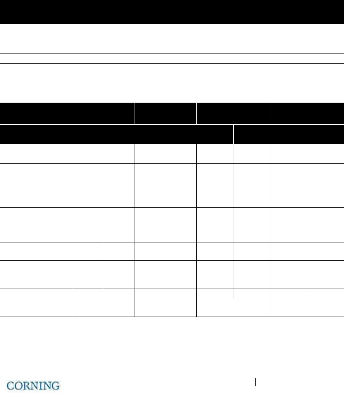
Appendix A: Specifications P/N 709C011801 Page 145
Appendix A: S pecifications
Supported Services
Technology
Frequency Range (MHz)
Service/Band Uplink (UL) Downlink (DL)
LTE 700MHz 698-716
777-787
728-746
746-756
CDMA/WCDMA**/ TDMA/GSM/LTE* CELL800 824-849 869-894
CDMA/WCDMA**/TDMA/GSM/LTE* PCS1900 1850-1915 1930-1995
WCDMA**/LTE* AWS2100 1710-1755 2110-2155
RF Parameters per Service
Service/Band LTE
700 MHz
CELL
800 MHz
PCS
1900 MHz
AWS
2100 MHz
RF
Parameter
DL UL DL UL DL UL DL UL
Frequency Range
[MHz]
728-746
746-756
698-716
777-787 869-894
824-849 1930-1995 1850-1910 2110-2155 1710-1755
Max Output Power
Per
Antenna Port
14 14 17 17
Max Input Power
[dBm] 0 to 37 15 to 37
0 to 37 0 to 37
Mean Gain [dB] -19 to 10 -19 to 10 -19 to 10 -19 to 10
Input IP3 [dBm]
AGC OFF Min -7 -7 -7 -7
Input IP3 [dBm]
AGC ON Min 5 5 5 5
SFDR** [dB] 59 63 63 59
Max Intermod
Distortion [dBm] -13 -13 -13 -13
UL NF*[dB] 12 12 12 12
Gain Flatness/Ripple
[dB] ±2.0 ±2.0 ±2.0 ±2.0
*Typical for single remote antenna
** SFDR calculated with BW of 1.23MHz for the CELL and PCS and with 5MHz for the LTE and AWS

Appendix A: Specifications P/N 709C011801 Page 146
Environmental, Standards and Optical
Environmental
Operating Temperature 0°C to +50°C (32°F to 122°F)
Storage -20°C to 85°C (-4°F to 185°F)
Standards and Approvals
Laser Safety FDA/CE 21 CFR 1040.10 and 1040.11 except for deviations pursuant to
laser notice no. 50 (July 26, 2001) and IEC 60825-1, Amendment 2
(January 2001)
EMC CE EN 301 489, EN55022, EN 61000
FCC 47 CFR Part 15, 22, 24, 27
Safety
Optical
Optical Output Power <9dBm
Max. Optical Budget 5 dB
Optical Connector OIM: MTP connector
RAU: LC/APC SM
Fiber Type Corning SMF-28 or Compatible
Wavelength 1310±10nm [@25 degrees C]
Maximum Distance (Headend to Remote End) 2Km [SMF]
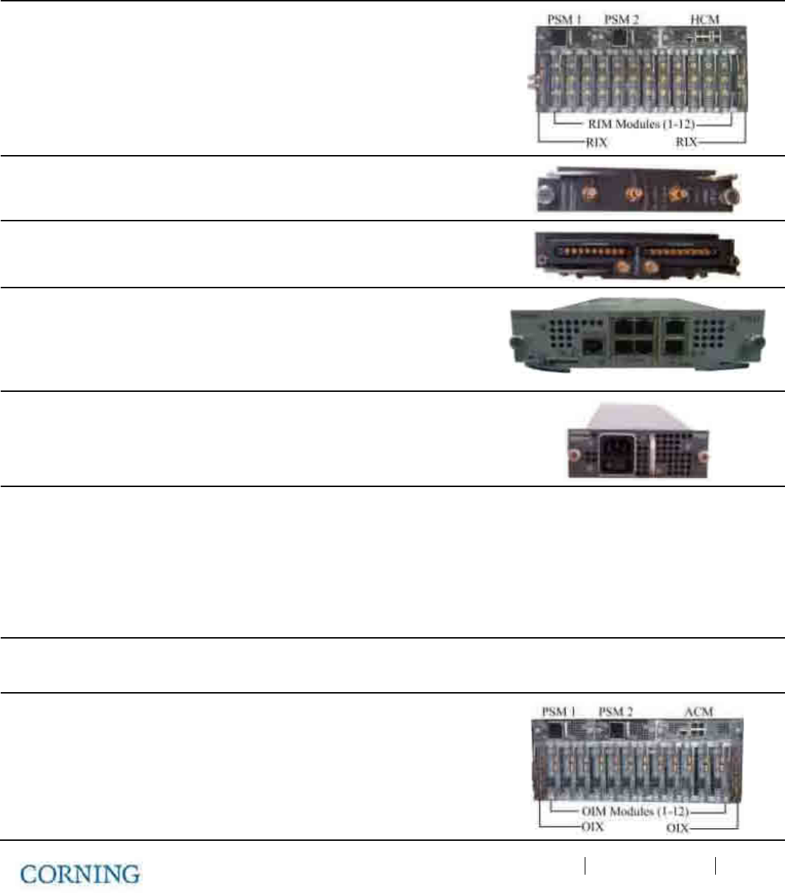
Appendix A: Specifications P/N 709C011801 Page 147
Unit Specifications
RF Coverage Component Specifications
Head End Unit (HEU)
HEU will host the following modules:
• RIM - Radio Interface Module; RF source conditioner. Up to 12 RIMs can
be hosted by the HEU.
• RIX - Radio Interface Expander; HEU to OIU interface module
• HCM - Headend Control Module; Overall system management module
• PSM - Power Supply Module; AC Power Supply
RIM Interfaces [3] QMA RF ports; UL, DL and Duplex
RIX Interfaces [2] 9-pin connectors [ one per OIX]
HCM Interfaces
[HEU Control Module]
ACM Interfaces: [4] RJ45 INTERNAL ports
Remote management: [1] RJ45 LAN port
Local Management: [1] RJ45 LOCAL port
Local Configuration: [1] CONSOLE port
System LEDs – PWR, RUN, SYS, FAN
PSM
Input: AC 100-220v
Power Consumption [Full Chassis]: 200W
ON/Off Switch
Optional: Additional PSM for redundancy
Physical
Characteristics
[Chassis]
Rackmount - 19" and 4U
Dimensions [H x W X D] US [International]: 7 x 17.3 x 18.95 in [177.8 x 440 x 481.7 mm]
Weight lbs [kg]: Chassis: 37 lbs [16.8 kg]
Per RIM: 1.9 lbs [0.9 kg]
Per RIX: 1.54 lbs [0.7 kg]
HCM: 2.2 lbs [1.0 kg]
PSM: 1.98 lbs [0.9 kg]
Optical Interface Unit [OIU]
OIU will host the following modules:
• OIM - Optical Interface Modules; Converts the RF to 3 optical links
• OIX - Optical Interface Expander; OIU to HEU interface module
• ACM - Auxiliary Control Module; Manages unit domestic modules,
"Slave" controller to the HCM
• PSM - Power Supply Module; Powers the unit
• ERFC85 - RF interface cable, 9-PIN 85 cm
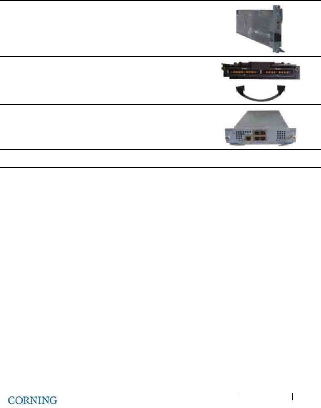
Appendix A: Specifications P/N 709C011801 Page 148
OIM Interfaces Optical Interface: [1] MTP Connector
[6] Kenpole connector for 1:1 direct signal
transportation, 3 UL and 3 for DL
OIX Interfaces RF Interface – [2] 9-pin connectors
ACM Interfaces [4] RJ45 INTERNAL ports
[1] RJ-45 CONSOLE port
System LEDs – PWR, RUN, SYS, FAN
PSM
(See PSM in HEU section for interfaces)
Power Consumption [Full Chassis]: 300W
Physical
Characteristics
[Chassis]
Mounting: Rackmount - 19" and 4U
Dimensions [H x W X D] US [International]: Chassis: 7 x 17.3 x 18.95 in [177.8 x 440 x
481.7 mm]
Cable Management tray: 6.96 x 20.02 x 4.35
in [176.9 x 508.6 x 110.6 mm]
Weight lbs [kg]:
Chassis : 37 lbs [16.8 kg]
Per OIM:1.5 lbs [0.7 kg]
Per OIX: 1.54 lbs [0.7 kg]
ACM: 2.2 lbs [1.0 kg]
PSM: 1.98 lbs [0.9 kg]
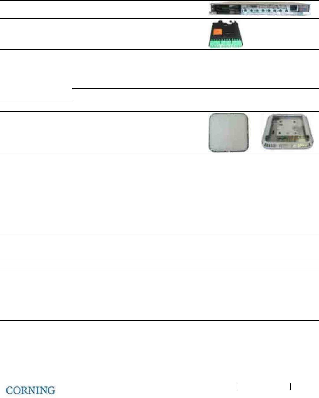
Appendix A: Specifications P/N 709C011801 Page 149
Intermediate Centralized Unit [ICU]
Chassis Interfaces Power Input: 110-240V AC, 50-60 Hz power
Output: [8] DC ports- 57V DC, Max. 60V [UL limit]
Edge Module
Interfaces
[1] MTP SM fiber port to
[6] LC/APC SM
Physical
Characteristics
Mounting: Rackmount - 19" 1U
Dimensions [HxWxD]: US [International] 17 x 15 x 19.2 in [430.5 x 379.8 x 488 mm]
Weight lbs [kg]: 5.5 lbs [2.5 kg] – without PSM
Remote Antenna Unit [RAU]
Supported Services SISO: CELL, PCS, AWS, 700LTE
MIMO: AWS/ 700LTE (with Expansion Module -
RxU)
Interface Connections [2] LC/APC SM fiber connectors; UL and DL
[2] DC power Inputs ports; Main and secondary
incase of PoE clients.
[2] QMA RF Ports; for External cavity filter
(In/Out) use
LTE and CELL filters
[1] External antenna
[1] RJ45 MGMT [local] connection
RxU module interface – Power, Digital and RF
GEM module Interface – Power and Digital
Antenna Omni Directional; 0dBi (15 Deg down from
horizon)
Broadband External antenna QMA Connector
Management Managed via the HCM
Physical
Characteristics
Mounting: Horizontal mount above or below Acoustic
Ceiling
Dimensions [H x W X D] US [International]: 13.1 x 13.1 x 4 in (including mounting
bracket) [332.7 x 332.7 x 101.6 mm]
Weight lbs [kg]: RAU only: 7.93 lbs [3.6 kg]
RAU + RXU + GEM: 12.12 lbs [5.5 kg]
Environment Ambient Temperature: Wall-mount installations: 45◦C [113◦F]
Ceiling-mount installations: 50
◦
C [122
◦
F]
*
Mounting below acoustic ceiling requires the appropriate support bracket (not supplied).
**Second connection used when a GEM module is installed
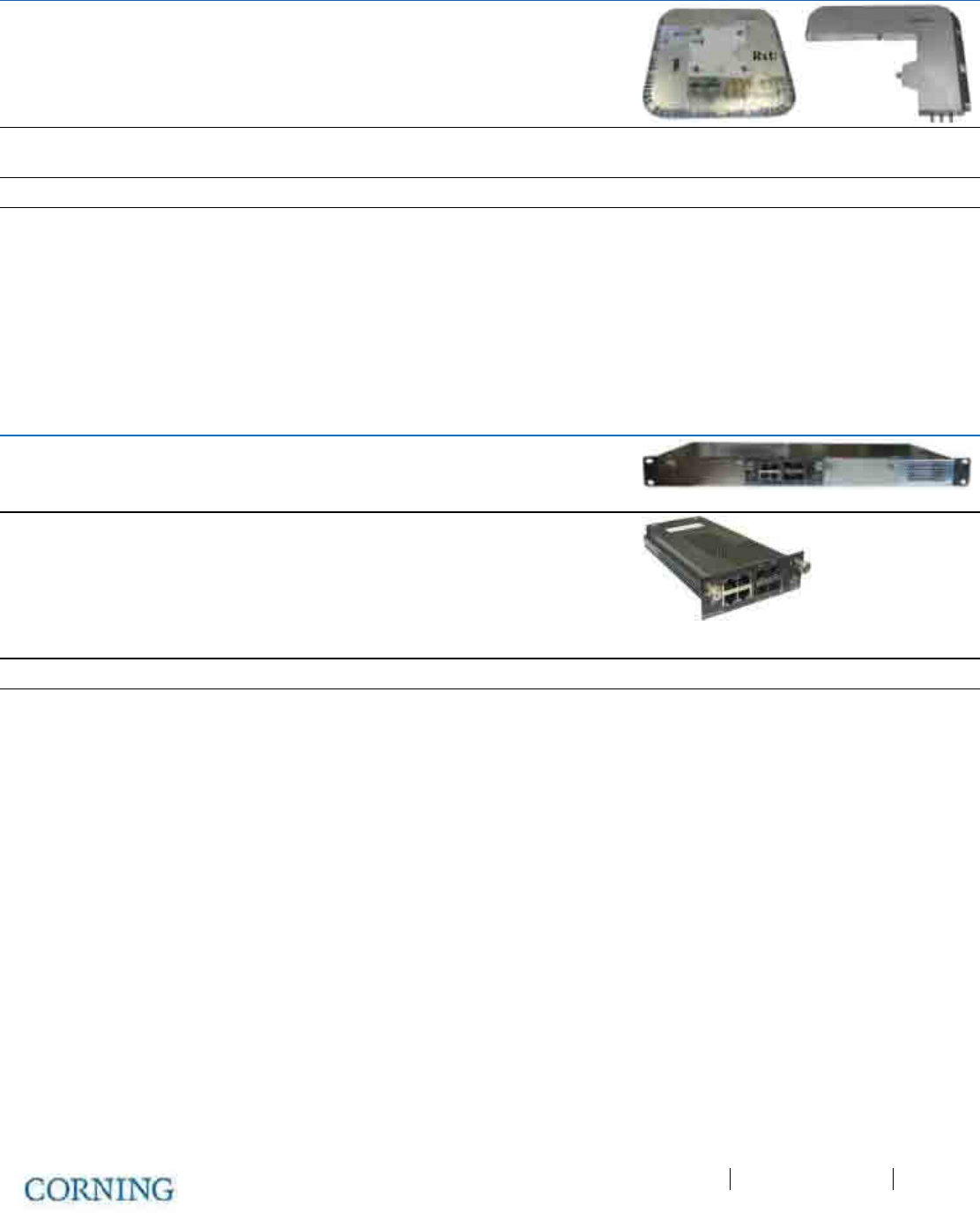
Appendix A: Specifications P/N 709C011801 Page 150
Remote Expansion Unit (RxU)
Services Add-on unit supporting two service
AWS MIMO and LTE700) MIMO
Interfaces
[3] pins for integration with RAU [power, control
and RF]
Management Management via host RAU
Physical Characteristics
Mounting: Installed in the RAU enclosure
Dimensions [H x W X D] US [International]: 1.09 x 12.8 x 9.8 in [27.7 x 327.5 x 250
mm]
Weight lbs [kg]: 3.08 lbs [1.4 kg]
Digital Coverage Component Specifications
Centralized Ethernet Unit (CEU)
Services Centralized Media Converter Unit Ethernet over
Fiber
Hosts Three Media Converter Modules [CEMs]
CEM Interfaces
[Centralized Ethernet
Module]
CEM supports [4] 10/100/1000BASE-T RJ-45
connectors
to [4] LC/UPC fiber connectors [4]
10/100/1000BASE-T Copper ports
[4] 1000BASE-X fiber
[1] USB serial port – service port
Power Input: 110-240vac, 50-60 Hz power
Physical
Characteristics
Mounting: Rackmount 19-in; 1U
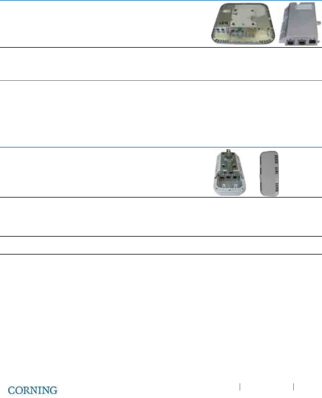
Appendix A: Specifications P/N 709C011801 Page 151
Gigabit Ethernet Module/Unit [GEM]/GEU]
Services GEM – Media converter, Ethernet over fiber to
Copper.
10/100/1000BASE-T Ethernet 1000BASE-X fiber.
[2] 802.3at compliant Power over Ethernet [PoE]
PSE ports
Interfaces [1] LC/UPC Fiber optic port
[2] RJ45 ports supporting
10/100/1000BASE-T copper interface with PoE +
802.3at PSE capability
Physical
Characteristics
Mounting: Standalone: GEU
Add-on: RAU Upgrade Module
Dimensions [HxWxD] US [International]: 1.28 x 3.79 x 5.95 in [32.7 x 96.3 x 151.3
mm]
Weight lbs [kg]: 1.1 lbs [0.5 kg]
Gigabit Ethernet Unit [GEU-S]
GEU-S will host the following module:
GEM; Gigabit Ethernet Module; Media converter, Ethernet over fiber to Copper.
Services Supplies power and management port for hosted
modules.
When it hosts a GEM it allows it to perform media
conversion services from Fiber to Copper and to
supply PoE+ PSE services
Interfaces DC PWR connector
Service Port – RJ45 (to GEM)
Physical
Characteristics
Mounting: Wall/Ceiling mount
Dimensions [HxWxD] US [International]: 5.01 x 10.51 x 3.26 in (including mounting
bracket) [127.5 x 267 x 83 mm]
Weight lbs [kg]: 2.64 lbs [1.2 kg]
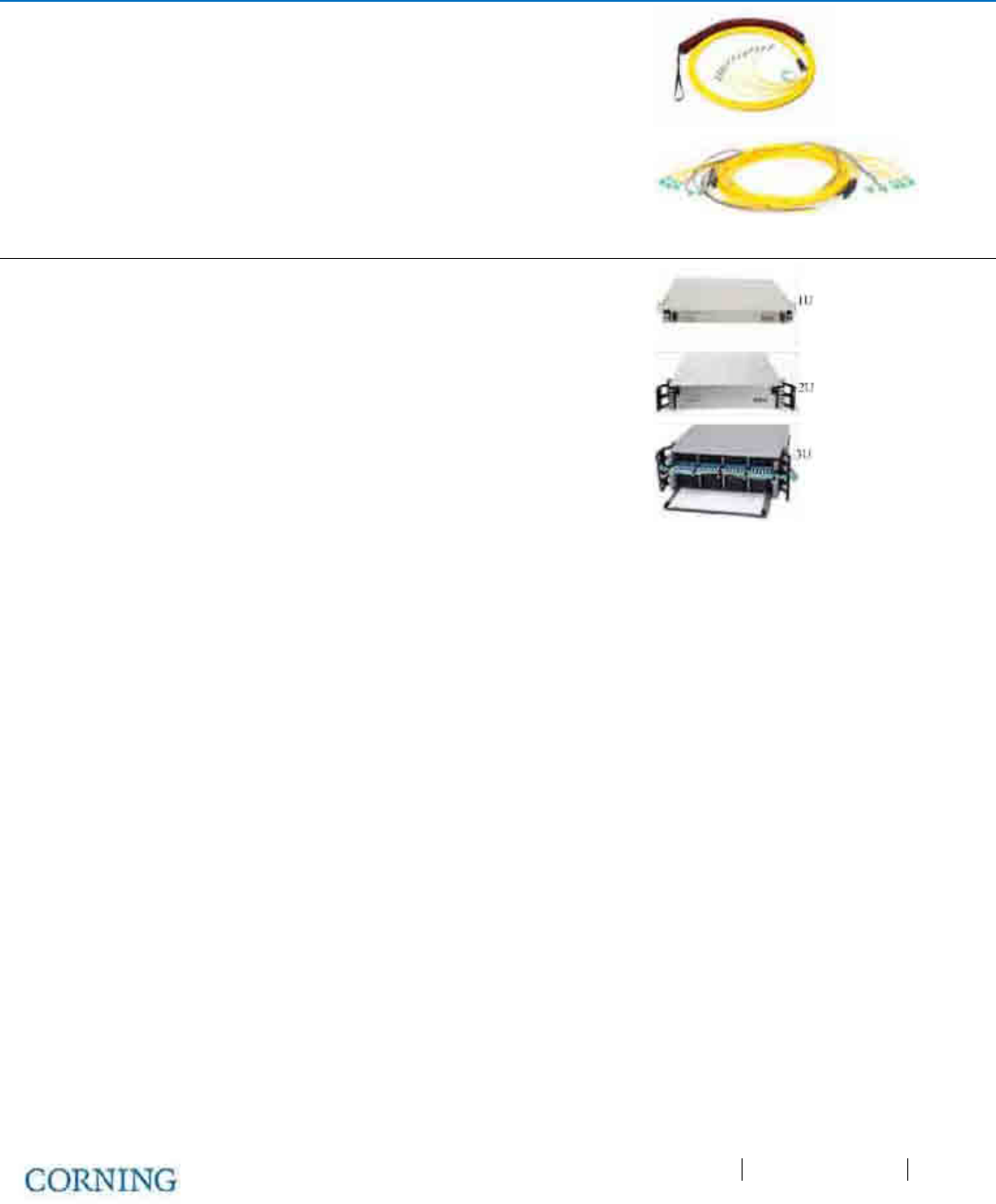
Appendix A: Specifications P/N 709C011801 Page 152
Optical: Cabling, Unit/Modules Specifications
Cabling: Vertical Plug & Play™ Plenum Optical cables
MTP Fiber Connectors
12 – 144 fibers
2-sided or 1-sided
Armored, Non-Armored
Horizontal Composite Plenum Tether Assemblies
Fiber: LC/APC, 2 – 24 fibers
Cu: 16AWG, 14AWG, 12AWG; 2 – 12
Conductors
Armored, Non-Armored
Fiber
Management
FMU 1U: 144 Fibers
2U: 288 Fibers
4U: 576 Fibers
Plug & Play™ Modules or Splice Cassettes

Appendix A: Specifications P/N 709C011801 Page 153
Ordering Information
HEU Chassis and Modules
Part Number Description
HEU Head End Unit Assembly, Support for 1-12 Radio Interface Modules (w/o RIMs)
PSM-HO Head End/Optical Interface Unit Power Supply; Includes US plug power cords
HCM Head End Control Module; Includes (2) RJ45 cables (2m)
FAM-HO Head End/Optical Interface Unit Fan module; One module including four fans
RIX Radio Interface Expander – HEU Expansion Module; Two must be ordered
RIM-L70 LTE 700 MHz service Radio Interface Module for HEU Chassis
RIM-C85 CELL 850 MHz service Radio Interface Module for HEU Chassis
RIM-P19 PCS 1900 MHz service Radio Interface Module for HEU Chassis
RIM-A17 AWS 17000 MHz service Radio Interface Module for HEU Chassis
RIM-L70-M LTE 700 MHz MIMO service Radio Interface Module for HEU Chassis
RIM-A17-M AWS 1700 MHz MIMO service Radio Interface Module for HEU Chassis
OIU Chassis and Modules
Part Number Description
OIU Optical Interface Unit Assembly, Support for 1-12 Optical Interface Modules (w/o OIMs)
OIM Optical Interface Module for OIU Chassis; 3 Optical Links
PSM-HO Head End/Optical Interface Unit Power Supply; Includes US plug power cords
ACM Auxiliary Control Module; Includes (2) RJ45 cables (2m)
FAM-HO Head End/Optical Interface Unit Fan module; One module including four fans
OIX Optical Interface Expander – OIU Expansion Module; Two must be ordered

Appendix A: Specifications P/N 709C011801 Page 154
Remote Units
Part Number Description
RAU-C85P19L70A17 CELL 850, PCS1900, LTE700 and AWS1700 Remote Antenna Unit Quad-service CELL, PCS, 700
MHz LTE and AWS; SMF
RAU-G-C85P19L70A17-E
Remote Antenna Unit with assembled GEM module; Support for CELL/PCS/ 700 MHz LTE and
AWS; Support for Ethernet services.
RXU-L70A17-M 700LTE/AWS MIMO Services Remote Expansion Unit for 700 MHz LTE and AWS MIMO support;
SMF
RAU-R-C85P19L70A17-M Remote Antenna Unit with assembled RxU;
RAU-R-G-C85P19L70A17-
M-E
Remote Antenna Unit with assembled RxU and GEM modules
ICU-1U Intermediate Centralized Unit; Hosts 4 x PSM-I modules. US power cord included.
PSM-I ICU Power Supply
Digital Path Units
Part Number Description
GEM Gigabit Ethernet Module
GEU Gigabit Ethernet Unit - docking station for GEM module (not included)
GEU-S Gigabit Ethernet Unit Standalone - docking station including assembled GEM module (for
standalone installations without RAU)
CEU Centralized Ethernet Unit; Host up to 3 x CEM modules
CEM Centralized Ethernet Module, includes; SFP and UPC to APC adapter
Accessories
Part Number Description
ETM Expander Termination Module; 50 Ohm Termination Expander Module
CblTray HEU/OIU Cable management tray + door sleeve; Chassis sleeve for managing cables and
door for covering front panel
ERFC85 Expander RF Cable; L= 85 cm; 9 pin SMP to SMP connector
ERFC60 Expander RF Cable; L= 60 cm; 9 pin SMP to SMP connector