Corning Optical Communication HX-WCS-SISO Optical Repeater Basic model name - HX-WCS-SISO Multi model name - HX-WCS-SISO-PLUS, HX-WCS-SISO-NU User Manual HX WCS
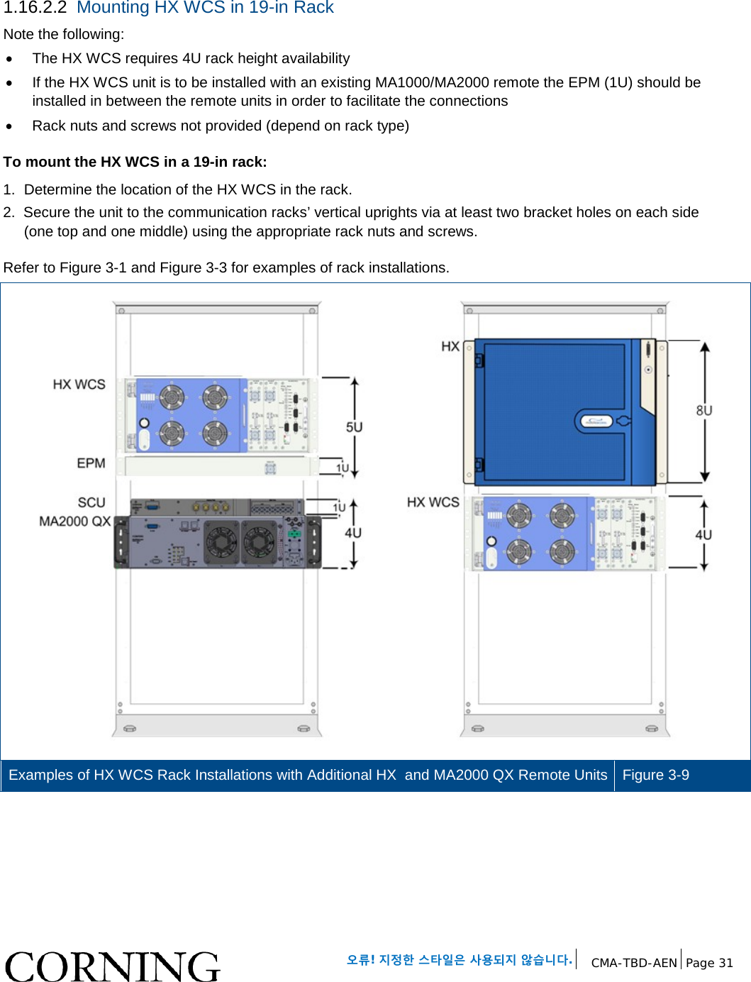
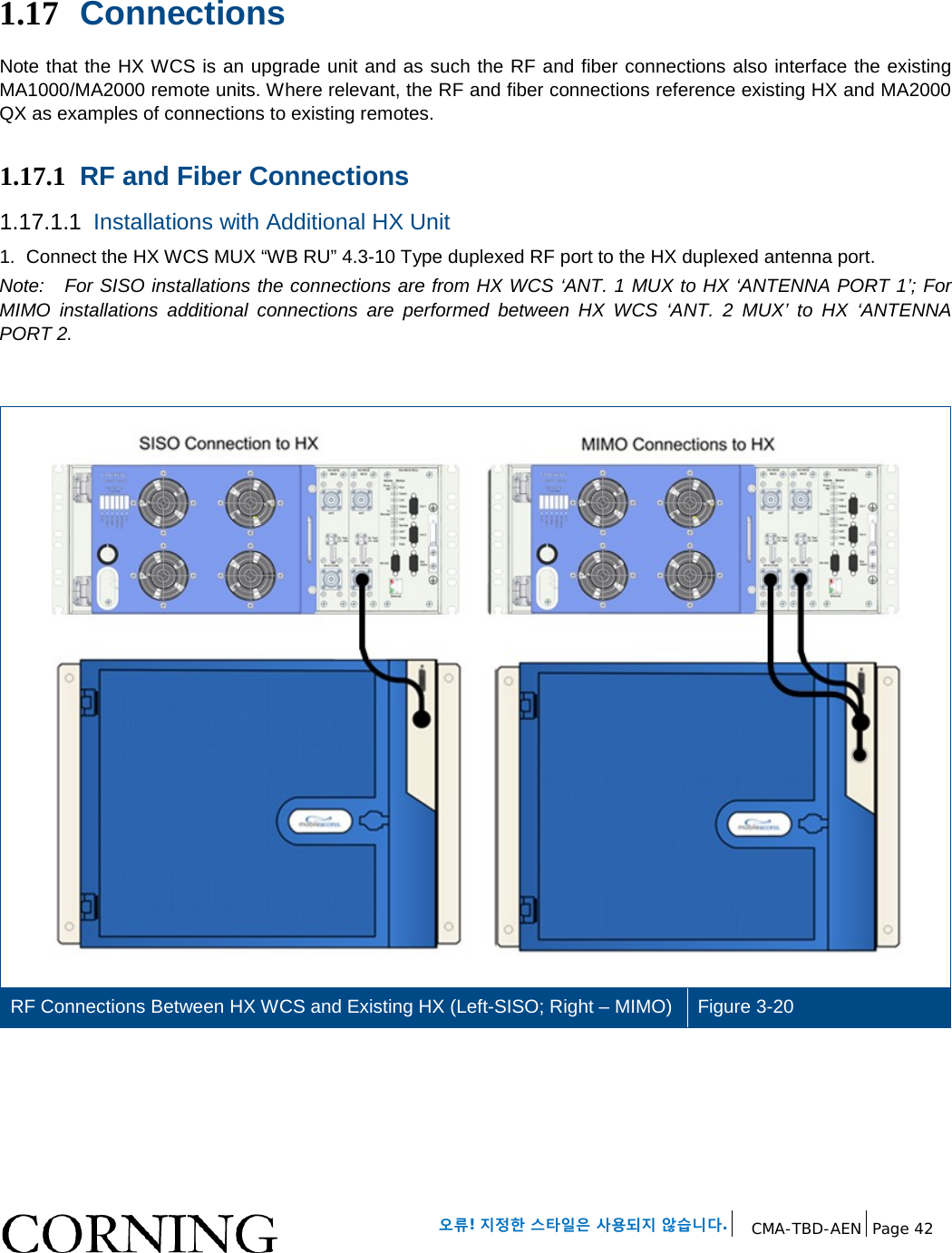
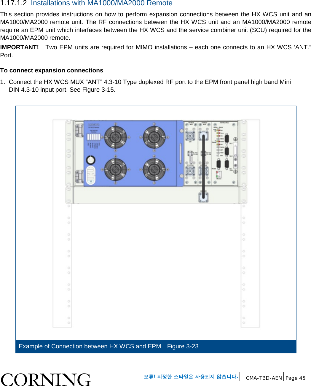
Corning Optical Communication Wireless Optical Repeater Basic model name - HX-WCS-SISO Multi model name - HX-WCS-SISO-PLUS, HX-WCS-SISO-NU HX WCS
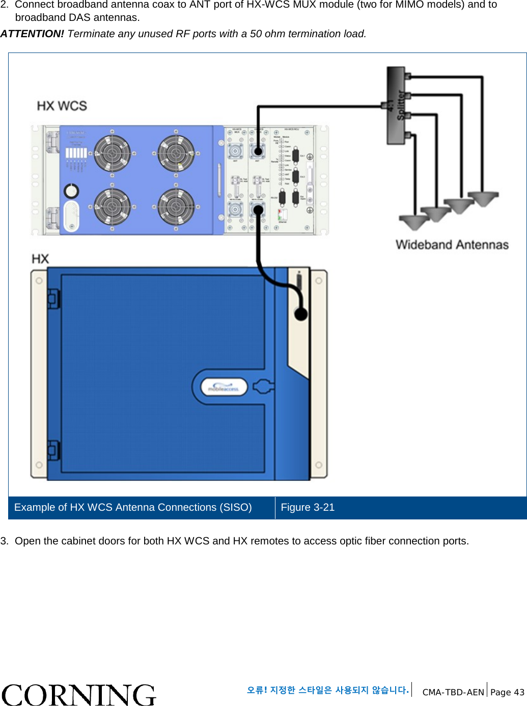
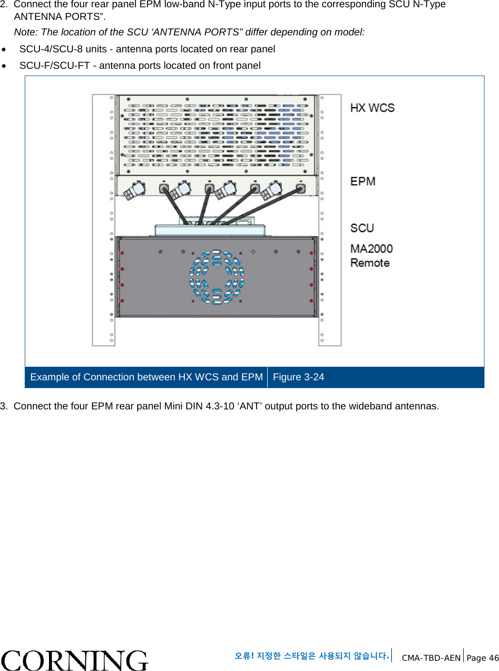
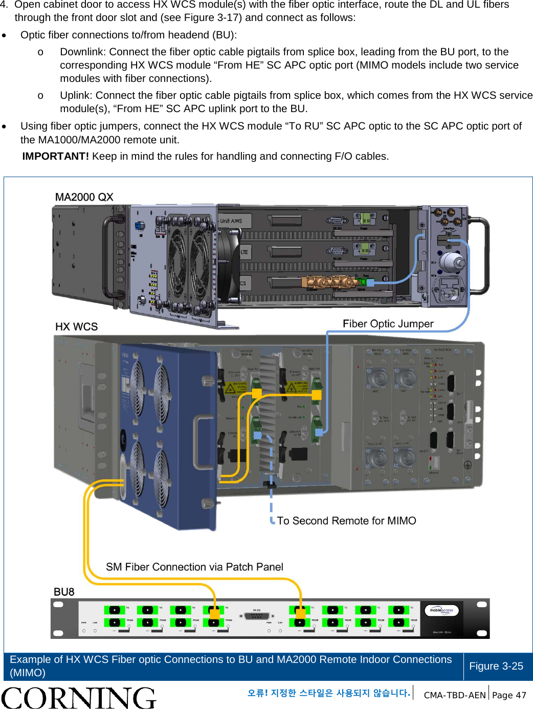
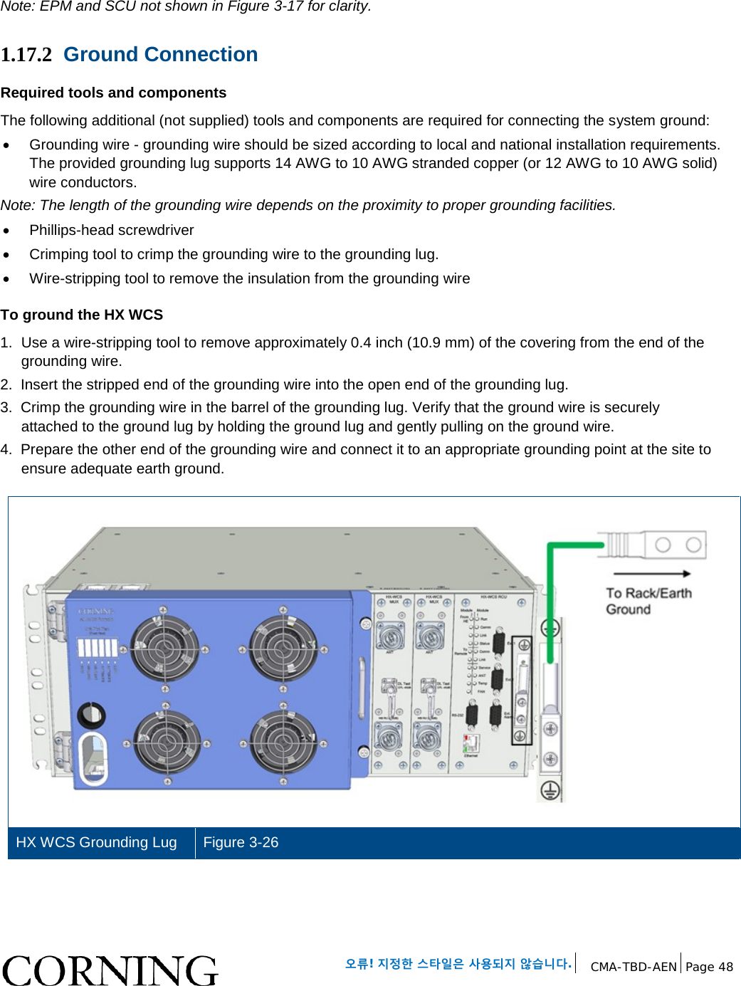
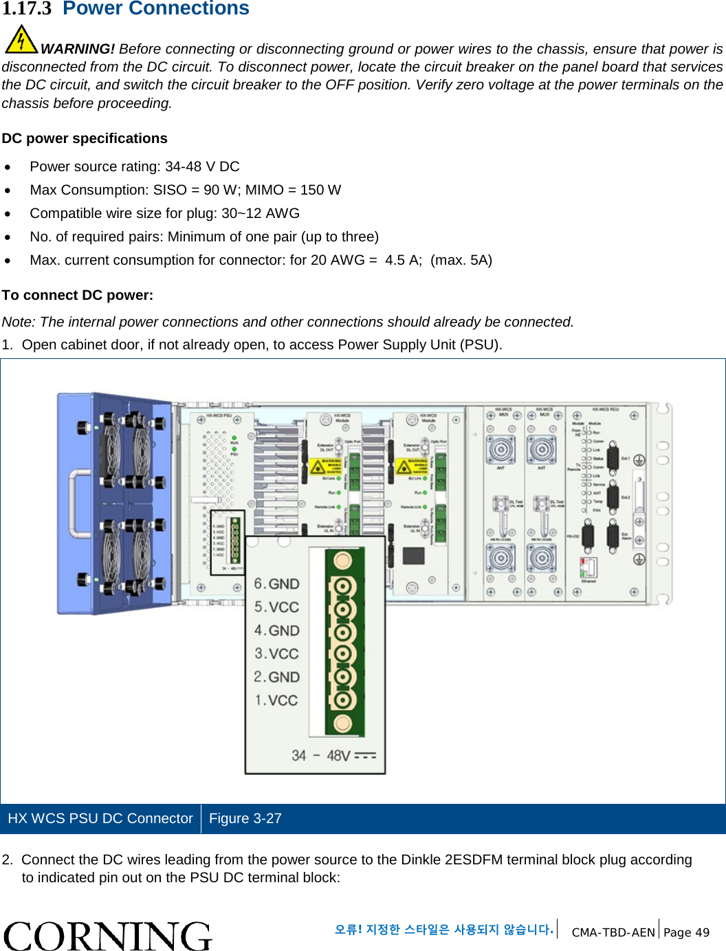
09 manual_UM_MobileAccessHX WCS 02OCTOBER2015_cs


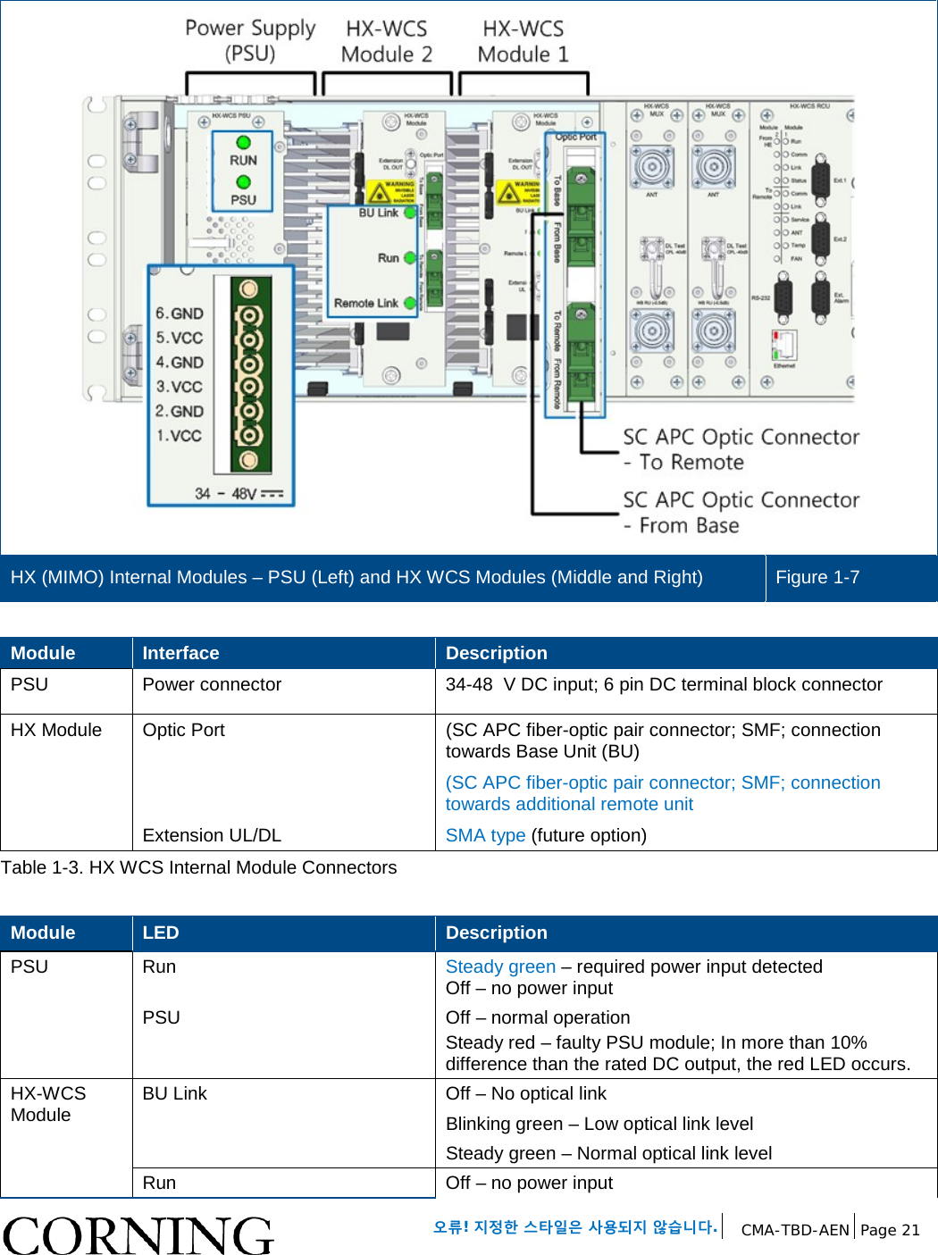
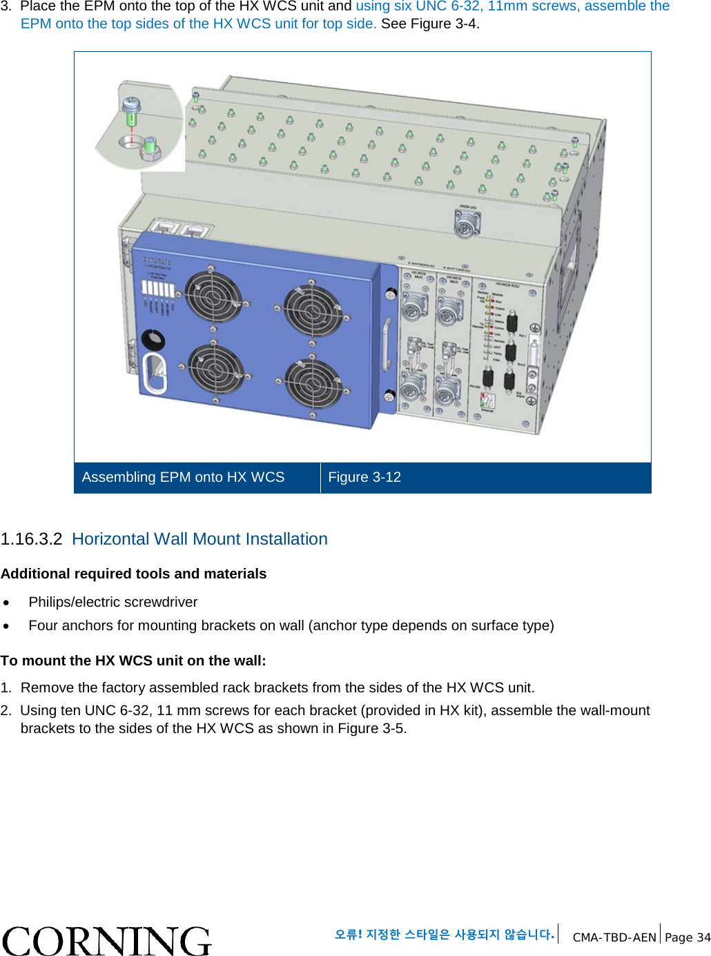
![오류! 지정한 스타일은 사용되지 않습니다. CMA-TBD-AEN Page 17 1.4 HX Unit Description The HX WCS unit consists of the following main modules: • RCU – Remote Control Unit; Includes status LEDs for each module and control ports • HX-WCS MUX – Multiplexer [ANT. 1 MUX (right) for SISO; ANT. 2 MUX (left) for MIMO] including interfaces to RF antennas and to MA1000/MA2000 units; combines signal sources additional external RF signals (when connected to HX unit and MA1000/MA2000 remote) while providing the proper filtering into a single antenna port • HX Module – [ANT. 1 (right) for SISO; ANT. 2 (left) for MIMO] Internal module that interfaces to the optical converter unit (Base Unit) connects via an SMF pair and supports one service. The HX WCS module provides the additional amplification on the DL signals routed from the BU towards the Multiplexer. • Power Supply - DC power; Internal module The unit plot plan is provided on the left side of the enclosure door: HX WCS Unit Plot Plan Figure 1-4 The following sections provide details on the front panel and internal module interfaces.](https://usermanual.wiki/Corning-Optical-Communication/HX-WCS-SISO/User-Guide-2813765-Page-17.png)
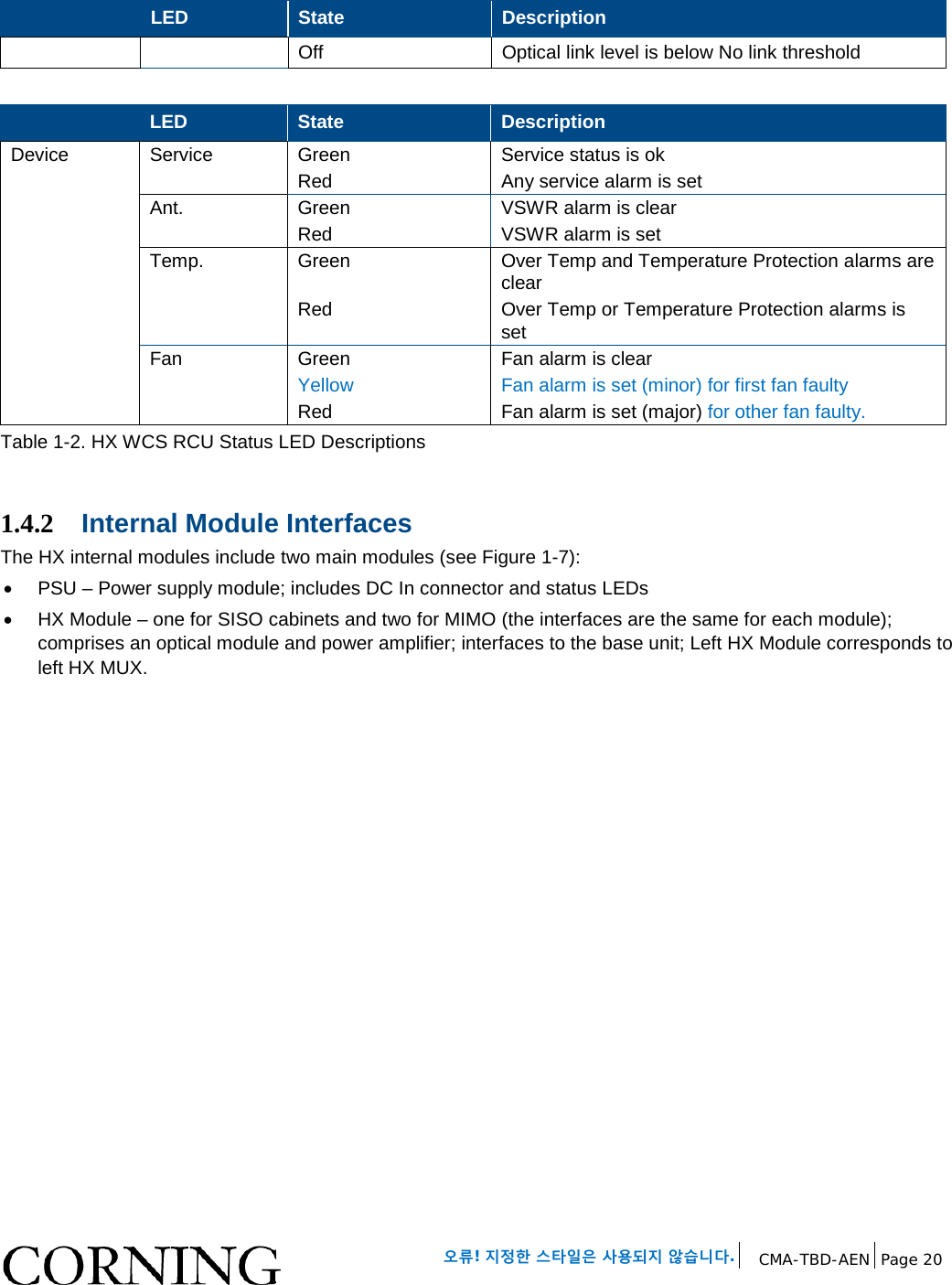
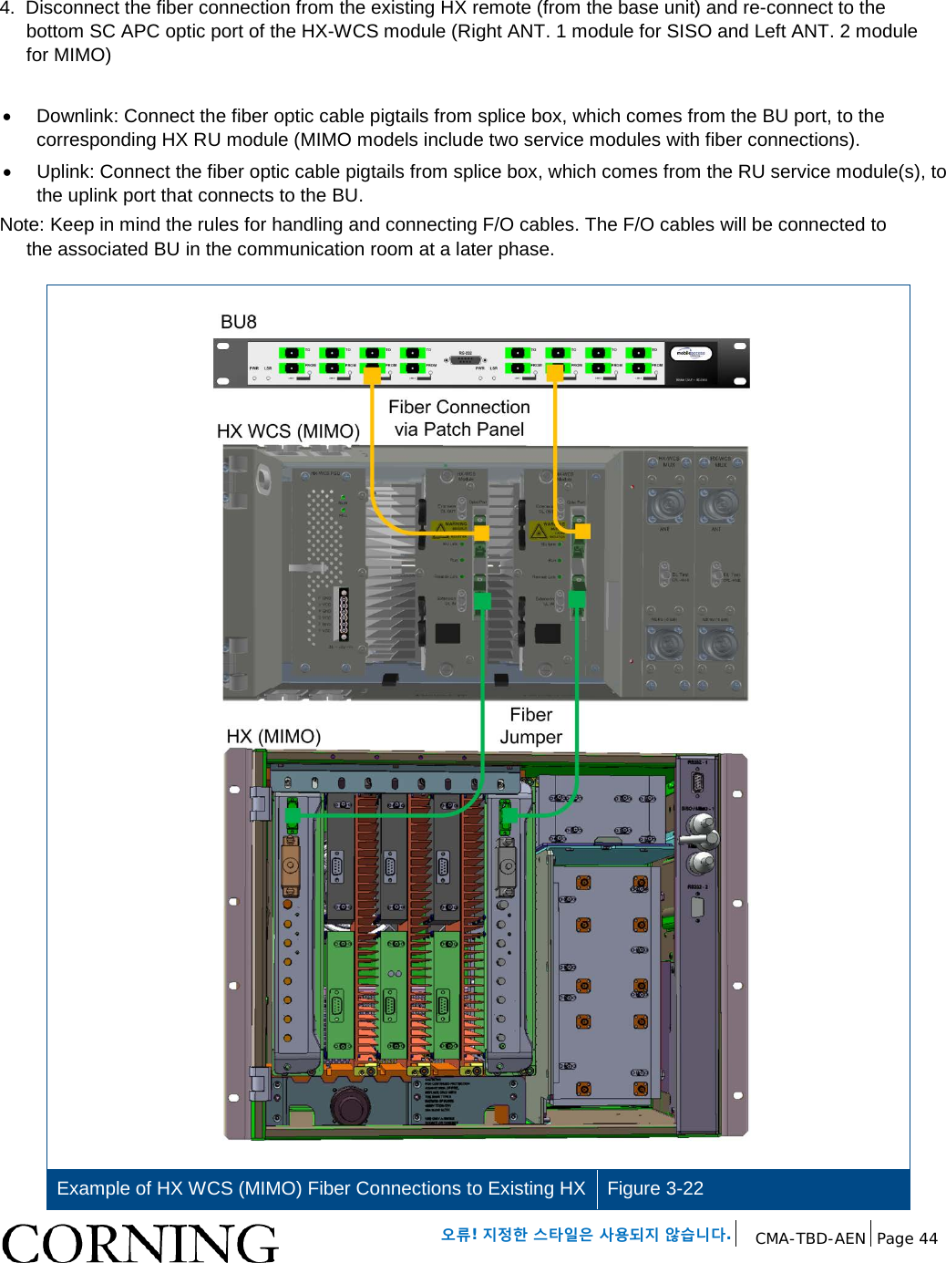
![오류! 지정한 스타일은 사용되지 않습니다. CMA-TBD-AEN Page 19 Refer to Figure 1-6 and Table 1-2 for description of HX status LEDs. HX WCS RCU Module Status LEDs Figure 1-6 Note: Module 1 and Module 2 LEDs correspond to installed modules [Module 1 for ANT. 1 (SISO); Module 2 for ANT. 2 (MIMO)]. LED State Description From HE (from headend) Run Blinking green Off Power input detected Unit powered off Comm Green Short blink upon receiving FSK message (Off at any other time) Link Steady green Optical link level is above normal threshold Blinking green Optical link level is lower than Normal threshold but above no-link threshold Off Optical link level is below No link threshold Status Green / Yellow / Red Color according to device’s overall status To Remote Comm Green Short blink upon receiving FSK message (Off at any other time) Link Steady green Optical link level is above normal threshold Blinking green Optical link level is lower than Normal threshold but above no-link threshold](https://usermanual.wiki/Corning-Optical-Communication/HX-WCS-SISO/User-Guide-2813765-Page-19.png)