Corning Optical Communication HX-WCS-SISO Optical Repeater Basic model name - HX-WCS-SISO Multi model name - HX-WCS-SISO-PLUS, HX-WCS-SISO-NU User Manual HX WCS
Corning Optical Communication Wireless Optical Repeater Basic model name - HX-WCS-SISO Multi model name - HX-WCS-SISO-PLUS, HX-WCS-SISO-NU HX WCS
09 manual_UM_MobileAccessHX WCS 02OCTOBER2015_cs

UM_MobileAccessHX WCS
Corning
Mid-Power HX WCS DAS System
User Manual

Warranties
CMA-318-AEN
Page 2
UM_MobileAccessHX WCS
Warranties
Hardware
Corning Optical Communications Wireless, Inc. (“Corning”) warrants to the original purchaser (“Customer”) that
for the duration of the warranty period, one (1) year, commencing on the date of shipment of the Hardware,
unless otherwise agreed in writing by Corning (the “Hardware Warranty Period”), the Hardware furnished by
Corning shall be free in all material respects from defects in material and workmanship, and shall conform to the
applicable portions of the Specifications, as defined below (the “Hardware Warranty”).
If notified by Customer of any such defects in material or workmanship or nonconformity with applicable portions
of the Specifications within the Hardware Warranty Period, Corning shall promptly, at its own election and
expense, repair or replace any such Hardware proven to be defective under the terms of this Hardware Warranty.
Such repair or replacement shall be Customer’s sole remedy and Corning’s’ sole obligation in the event this
Hardware Warranty is invoked. If any components comprising a part of the Hardware are replaced or repaired
during the Hardware Warranty Period, the Hardware Warranty Period for such repaired or replaced components
shall extend to the longer of (i) the balance of the Hardware Warranty Period or (ii) three (3) months from the date
of repair or replacement. For purposes of this Warranty, “Specifications” shall mean the specifications and
performance standards of the Products as set forth in documents published by Corning
Corning and delivered to Customer which contain technical specifications or performance standards for the
Products.
If Customer invokes this Hardware Warranty, it shall notify Corning promptly of the claimed defect.
Customer will allow Corning to inspect the Hardware at Customer’s location, or to return the Hardware to Corning’
closest repair facility. For Hardware returned to Corning’s’ repair facility, Customer shall be responsible for
payment of all transportation and freight costs (including insurance) to Corning’s’ repair facility, and Corning shall
be responsible for all transportation and freight costs (including insurance) incurred in connection with the
shipment of such Hardware to other repair facilities of Corning and/or its return to Customer.
Notwithstanding the foregoing, in no event will Corning be liable for damage to Products resulting from improper
handling during or after shipment, misuse, neglect, improper installation, operation or repair (other than by
authorized Corning personnel), alteration, accident, or for any other cause not attributable to defects in materials
or workmanship on the part of Corning. Corning shall not reimburse or make any allowance to Customer for any
labor charges incurred by Customer for replacement or repair of any goods unless such charges are authorized in
advance in writing by Corning.
Software Warranty
Corning warrants to the original purchaser (“Customer”) that for the duration of the warranty period, one (1) year,
commencing on the date of shipment of the Software, unless otherwise agreed in writing by Corning
(the “Software Warranty Period”), the Software shall conform with, and perform the functions set forth in the
Specifications, and shall be free from defects in material or workmanship (the “Software Warranty”). In the event
the Software is proven to be defective under the terms of this Software Warranty, Corning shall correct such
defects or failure and ensure that the Software conforms with, and performs the functions set forth in, the
Specifications. Customer will allow Corning to inspect the Software at Customer’s location or to return it to
Corning’s closest repair facility.
Notwithstanding the foregoing, Corning shall have no obligation under the Software Warranty if the

Warranties
P/N 709C015102
Page 3
Software is modified or used with hardware or software not supplied or approved by Corning or if the Software is
subject to abuse, improper installation or application, accident, electrical or environmental over-stress, negligence
in use, storage, transportation or handling.
Third-party software distributed with the Software may carry certain warranties which, to the maximum extent
allowed by law, Corning hereby assigns, transfers and otherwise conveys to Customer, provided, however, that
Corning itself provides no warranty of any kind, express, implied, statutory or otherwise, for any third-party
software provided hereunder.
Corning does not warrant any hardware, software or services not provided by Corning.
THIS WARRANTY IS THE ONLY WARRANTY MADE BY CORNING AND IS IN LIEU OF ALL OTHER
WARRANTIES, EXPRESS OR IMPLIED INCLUDING, BUT NOT LIMITED TO, THE IMPLIED WARRANTIES OF
MERCHANTABILITY AND FITNESS FOR A PARTICULAR PURPOSE. CORNING S SHALL NOT BE LIABLE
FOR ANY OTHER DAMAGE INCLUDING, BUT NOT LIMITED TO, INDIRECT, SPECIAL OR CONSEQUENTIAL
DAMAGES ARISING OUT OF OR
IN CONNECTION WITH FURNISHING OF GOODS, PARTS AND SERVICE HEREUNDER, OR THE
PERFORMANCE, USE OF, OR INABILITY TO USE THE GOODS, PARTS AND SERVICE. CORNING SALES
AGENTS OR REPRESENTATIVES ARE NOT AUTHORIZED TO MAKE COMMITMENTS ON WARRANTY
RETURNS.
Returns
In the event that it is necessary to return any product against above warranty, the following procedure shall be
followed:
1. Return authorization is to be received from Corning prior to returning any unit. Advise Corning of the model,
Serial number, and discrepancy. The unit may then be forwarded to Corning, transportation prepaid. Devices
returned collect or without authorization may not be accepted.
2. Prior to repair, Corning will advise the customer of our test results and any charges for repairing customer-
caused problems or out-of-warranty conditions etc.
3. Repaired products are warranted for the balance of the original warranty period, or at least 90 days from date
of shipment.
Limitations of Liabilities
Corning’s liability on any claim, of any kind, including negligence for any loss or damage arising from, connected
with, or resulting from the purchase order, contract, quotation, or from the performance or breach thereof, or from
the design, manufacture, sale, delivery, installation, inspection, operation or use of any equipment covered by or
furnished under this contact, shall in no case exceed the purchase price of the device which gives rise to the
claim.
Except as expressly provided herein, Corning makes no warranty, expressed or implied, with respect to any
goods, parts and services provided in connection with this agreement including, but not limited to, the implied
warranties of merchantability and fitness for a particular purpose. Corning shall not be liable for any other damage
including, but not limited to, indirect, special or consequential damages arising out of or in connection with
furnishing of goods, parts and service hereunder, or the performance, use of, or inability to use the goods, parts
and service.

Warranties
P/N 709C015102
Page 4
Reporting Defects
The units were inspected before shipment and found to be free of mechanical and electrical defects. Examine the
units for any damage that may have been caused in transit. If damage is discovered, file a claim with the freight
carrier immediately. Notify Corning as soon as possible in writing.
Note: Keep all packing material until you have completed the inspection

Warnings and Admonishments
P/N 709C015102
Page 5
Warnings and Admonishments
There may be situations, particularly for workplace environments near high-powered RF sources, where
recommended limits for safe exposure of human beings to RF energy could be exceeded. In such cases,
restrictive measures or actions may be necessary to ensure the safe use of RF energy.
The equipment has been designed and constructed to prevent, as far as reasonably, practicable danger. Any
work activity on or near equipment involving installation, operation or maintenance must be, as far as reasonably,
free from danger.
Where there is a risk of damage to electrical systems involving adverse weather, extreme temperatures, wet,
corrosive or dirty conditions, flammable or explosive atmospheres, the system must be suitably installed to
prevent danger.
Equipment provided for the purpose of protecting individuals from electrical risk must be suitable for the purpose
and properly maintained and used. This covers a range of activities including lifting, lowering, pushing, pulling,
carrying, moving, holding or restraining an object, animal or person from the equipment. It also covers activities
that require the use of force or effort, such as pulling a lever, or operating power tools.
Where some of the abovementioned activities are required, the equipment must be handled with care to avoid
being damaged.
Observe standard precautions for handling ESD-sensitive devices. Assume that all solid-state electronic devices
are ESD-sensitive. Ensure the use of a grounded wrist strap or equivalent while working with ESD-sensitive
devices. Transport, store, and handle ESD-sensitive devices in static-safe environments.
RF Safety
WARNING! To comply with FCC RF exposure compliance requirements, each individual antenna used for this
transmitter must be installed to provide a separation distance greater than 115 cm or more from all persons during
normal operation and must not be co-located with any other antenna for meeting RF exposure requirements.
WARNING! Antenna gain should not exceed 12.5 dBi.
WARNING! Each individual antenna used for this transmitter must be installed to provide a separation distance
greater than 115 cm or more from all persons and must not be co-located with any other antenna for meeting RF
exposure requirements.
WARNING! The design of the antenna installation needs to be implemented in such a way so as to ensure RF
radiation safety levels and non-environmental pollution during operation.
Compliance with RF safety requirements:
• Corning products have no inherent significant RF radiation.
• The RF level on the downlink is very low at the downlink ports. Therefore, there is no dangerous RF radiation
when the antenna is not connected.
Power requirements for DC Inputs
WARNING! Only use a special DC supply cable with connector
WARNING! Always keep DC IN connectors connected during the product operation

RF Safety
P/N 709C015102
Page 6
WARNING! Disconnect all power from the equipment by means of an external circuit breaker before connecting
or disconnecting the DC IN connectors.
WARNING! UL certified power supply.
Laser Safety
P/N 709C015102
Page 7
Laser Safety
Fiber optic ports of the MobileAccessHX system emit invisible laser radiation at the 1310/1550 nm wavelength
window.
The laser apertures /outputs are the green SC/APC Bulkhead adapters located on the front panel of the
equipment.
The product is Class 1/Hazard level 1
External optical power is less than 10 mW, Internal optical power is less than 500 mW.
To avoid eye injury never look directly into the optical ports, patchcords or optical cables. Do not stare into beam
or view directly with optical instruments. Always assume that optical outputs are on.
Only technicians familiar with fiber optic safety practices and procedures should perform optical fiber connections
and disconnections of MobileAccessHX devices and the associated cables.
MobileAccessHX has been tested and certified as a Class 1 Laser product to IEC/EN 60825-1 (2007). It also
meets the requirements for a Hazard Level 1 laser product to IEC/EN 60825-2: 2004 to the same degree.
MobileAccessHX complies with 21 CFR 1040.10 and 1040.11 except for deviations pursuant to Laser Notice NO.
50 (2007).
Care of Fiber Optic Connectors
Do not remove the protective covers on the fiber optic connectors until a connection is ready to be made. Do not
leave connectors uncovered when not connected.
The tip of the fiber optic connector should not come into contact with any object or dust.
Regulatory Compliance Information
WARNINGS!
• This is NOT a CONSUMER device. It is designed for installation by FCC LICENCEES and QUALIFIED
INSTALLERS. You MUST have an FCC LICENSE or express consent of an FCC Licensee to operate this
device. Unauthorized use may result in significant forfeiture penalties, including penalties in excess of
$100,000 for each continuing violation.
• ANTENNAS:
(1) Use only authorized and approved antennas, cables and/or coupling devices! The use of unapproved
antennas, cables or coupling devices could cause damage and may be of violation of FCC regulations.
The use of unapproved antennas, cables and/or coupling devices is illegal under FCC regulations and
may subject the user to fines.
(2) Caution messages for use of unauthorized antennas, cables, and/or coupling devices not conforming
with ERP/EIRP and/or indoor-only restrictions.
Standards and Certifications
P/N 709C015102
Page 8
Standards and Certifications
Corning products have met the approvals of the following certifying organizations:
Category Standards
Safety: UL 60950-1
CAN/CSA-C22.2 No.60950
Laser Safety:
SCDRH 21 CFR 1040.10, 1040.11 (Except for
deviations per notice No.50, July 26, 2001)
IEC/EN 60825-1:1994+A1:2002+A2:2001
Radio: FCC 47: Part 2, 27
ISO: ISO 9001: 2000 and ISO 13485: 2003
Licensee Contact Information
Industrial Boosters may only be used by FCC licensees or those given express (individualized) consent of license.
Corning certifies all of the VARs listed as licensed installers for Corning. For the list of licensed VARs, please
contact the Corning Tech Support Hotline: (US) 410-553-2086 or 800-787-1266.
About this Guide
This Installation Guide describes how to perform the physical installation of the MobileAccessHX unit. The
installation procedures of other units (e.g. RIU, OCH-HX, SC-450) relevant to the system are detailed in their user
manuals (see Additional Relevant Documentation below).
Additional Relevant Documents
The following documents are required if the corresponding units are included in your system.
Document Name
RIU Installation and Configuration Guide
MA2000 User Manual (includes BU information)
System Controller (SC-450) User Manual
MA Software Version Update Tool

List of Acronyms
P/N 709C015102
Page 9
List of Acronyms
BTS Base Transceiver Station
BTSC Base Transceiver Station Conditioner
BU Base Unit
DL Downlink
HX High Power Remote
MUX Multiplexer
PA Power Amplifier
PSU Power Supply Unit
RCU Remote Control Unit
RIU Radio Interface Unit
RU Remote Unit (module)
SC-450 System Controller
UL Uplink

Table of Contents
P/N 709C015102
Page 10
Table of Contents
Warranties ................................................................................................................................ 2
Hardware ....................................................................................................................................................... 2
Software Warranty ........................................................................................................................................ 2
Returns .......................................................................................................................................................... 3
Limitations of Liabilities ................................................................................................................................. 3
Reporting Defects ......................................................................................................................................... 4
Warnings and Admonishments ............................................................................................... 5
RF Safety .................................................................................................................................. 5
Compliance with RF safety requirements: .................................................................................................... 5
Power requirements for DC Inputs ................................................................................................................ 5
Laser Safety .............................................................................................................................. 7
Care of Fiber Optic Connectors .................................................................................................................... 7
Regulatory Compliance Information ....................................................................................... 7
Standards and Certifications ................................................................................................... 8
Licensee Contact Information ................................................................................................. 8
About this Guide ...................................................................................................................... 8
List of Acronyms ...................................................................................................................... 9
Table of Contents ................................................................................................................... 10
1 Introduction ..................................................................................................................... 13
1.1 Key Features and Capabilities ............................................................................................................ 14
1.2 System Architecture ............................................................................................................................ 15
1.3 System Monitoring and Management ................................................................................................. 16
1.4 HX Unit Description ............................................................................................................................. 17
1.4.1 HX WCS External Interfaces ..................................................................................................... 18
1.4.2 Internal Module Interfaces ........................................................................................................ 20
1.5 External Passive Module (EPM).......................................................................................................... 23
2 Installation Guidelines .................................................................................................... 24
2.1 Site Considerations ............................................................................................................................. 24
2.2 Environmental ..................................................................................................................................... 24
2.3 Installation Requirements .................................................................................................................... 24

Table of Contents
P/N 709C015102
Page 11
2.4 Fiber Optic Requirements ................................................................................................................... 25
2.4.1 Authorized Optic Cables ........................................................................................................... 25
2.4.2 Fiber Optic Rules ...................................................................................................................... 25
2.5 RF Coaxial Cable Guidelines .............................................................................................................. 26
2.5.1 General Cable Installation Procedures ..................................................................................... 26
2.5.2 RF Rules ................................................................................................................................... 26
2.5.3 Coax Cable Lengths and Losses .............................................................................................. 26
2.5.4 Cable Routing ........................................................................................................................... 27
2.6 Antenna Specifications and Guidelines ............................................................................................... 27
2.6.1 Authorized Antennas and Couplers .......................................................................................... 27
2.6.2 General Antenna Installation Guidelines ................................................................................... 28
2.7 Grounding Requirement ...................................................................................................................... 28
2.8 Manual Handling ................................................................................................................................. 28
2.9 Installation Requirements .................................................................................................................... 28
3 HX Physical Installation .................................................................................................. 29
3.1 Unpacking and Inspection ................................................................................................................... 29
3.2 Mounting .............................................................................................................................................. 30
3.2.1 General Instructions .................................................................................................................. 30
3.2.2 Rack Mount Installation ............................................................................................................. 30
3.2.2.1 Rack Installation General Safety Instructions .............................................................. 30
3.2.2.2 Mounting HX WCS in 19-in Rack ................................................................................. 31
3.2.3 Wall-Mount Installation .............................................................................................................. 33
3.2.3.1 Assembling EPM to HX WCS (for Configurations with EPM) ...................................... 33
3.2.3.2 Horizontal Wall Mount Installation ............................................................................... 34
3.2.3.3 Vertical Wall Mount Installation .................................................................................... 38
3.3 Connections......................................................................................................................................... 42
3.3.1 RF and Fiber Connections ........................................................................................................ 42
3.3.1.1 Installations with Additional HX Unit ............................................................................ 42
3.3.1.2 Installations with MA1000/MA2000 Remote ................................................................ 45
3.3.2 Ground Connection ................................................................................................................... 48
3.3.3 Power Connections ................................................................................................................... 49
3.4 Verifying Normal Operation ................................................................................................................. 50
Appendix A: System Specifications...................................................................................... 51
RF Parameters ............................................................................................................................................ 51
Supported Services ............................................................................................................................. 51
RF Parameters per Service Antenna Port ........................................................................................... 51
RF Parameters for Diplexer External Input Port .................................................................................. 52
Optical Specifications .................................................................................................................................. 52
Physical Specifications................................................................................................................................ 53
Environmental Specifications ...................................................................................................................... 53
Standards and Approvals ............................................................................................................................ 54

Table of Contents
P/N 709C015102
Page 12
Appendix B: Ordering Information ........................................................................................ 55
MobileAccessHX WCS Remote Units ......................................................................................................... 55
오류! 지정한 스타일은 사용되지 않습니다.
CMA-318-AEN
Page 13
• Introduction
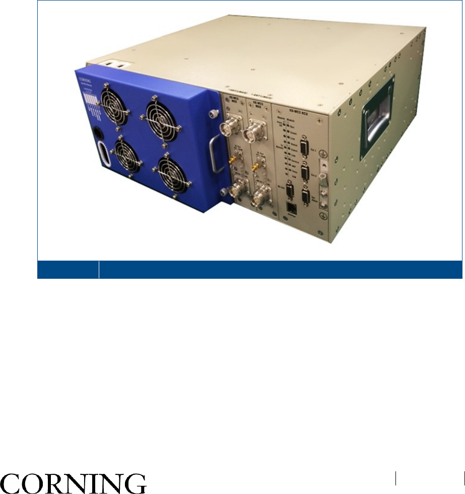
MobileAccessHX WCS is a mid-power, remote solution designed to be integrated into existing MobileAccess1000
(MA1000) and MobileAccess2000 (MA2000) Distributed Antenna Systems (DAS) already deployed in the field. It
is a fiber fed, compact unit which provides support for the WCS 2300 MHz band and is designed to complement
the MA1000/MA2000 and other MobileAccessHX flavors while enhancing RF open space coverage for large-
scale public venues such as campuses, stadiums, convention centers, hotels, airports and train stations.
Using low-loss fiber optic cabling, remote units can cover distances of up to 12.75 mi (2 km) from the BTS signal
sources at the headend. HX WCS requires minimum addition of hardware to the headend (WCS BTSC) and
utilizes existing fiber and antenna overlay. HX WCS MIMO takes full advantage of MIMO technology by using
spatial multiplexing to deliver higher spectral efficiency and preventing the degradation of quality while
significantly increasing throughput on the same spectrum.
HX WCS Figure 1-1

오류! 지정한 스타일은 사용되지 않습니다.
CMA-TBD-AEN
Page 14
1.1 Key Features and Capabilities
• Service Platform: Accommodates LTE and provides SISO/MIMO configuration for WCS band.
• Cost-Effective High Power: Optimizes and reduces the number of antennas required to cover open areas
by offering up to 33 dBm (2 W) composite power per frequency band.
• Scalability: Supports either SISO or MIMO service in a single compact enclosure.
• Operator-Grade Operation: Advanced signal handling and management ensures operator-grade
performance in multi-operator deployments.
• Design and Deployment Flexibility: Antenna splitting schemes are possible due to the higher power output
capability.
• Compatibility: Connects existing MobileAccess1000, MobileAccess2000 and MobileAccessHX remote units
to allow common antenna overlay; Shares a common headend and EMS in a single deployment.
• Monitoring and Web Management: All status LEDs are located on front panel; Web management via the
SC-450 controller (v7.2 and higher)
오류! 지정한 스타일은 사용되지 않습니다.
CMA-TBD-AEN
Page 15
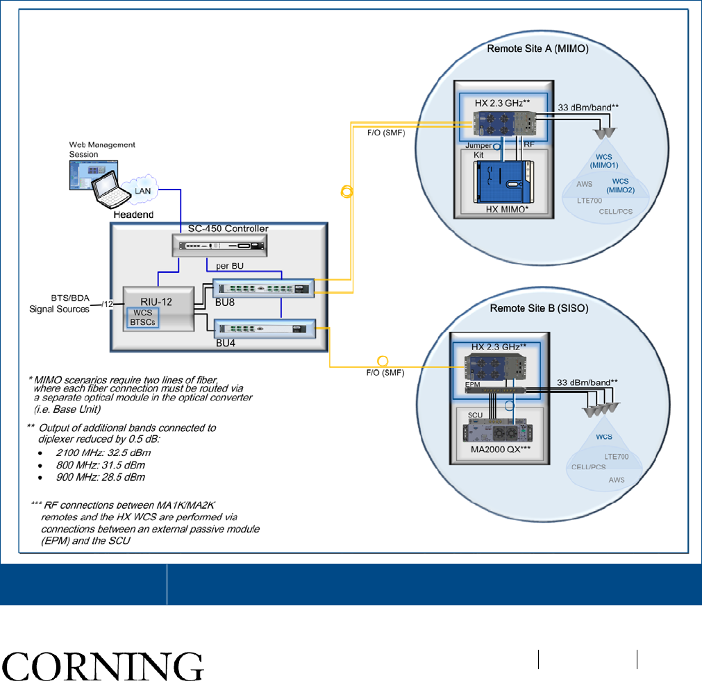
1.2 System Architecture
MobileAccessHX WCS provides a complete solution consisting of HX remote unit(s) at the remote locations and
headend elements.
In the downlink, at the headend, the BTS or BDA signal is conditioned by the RIU, ensuring a constant RF level.
The conditioned signal is then converted by the Base Unit (BU) to an optical signal for transport over single or
multi-mode fiber to the HX remote unit, located at the remote location. In the uplink, the process is reversed.
The HX Remote Unit (SISO/MIMO) consists of a compact enclosure that houses the RF module, power elements
and the required interfaces. The RF module supports the WCS band. An interface duplexing port is located on the
remote to allow additional HX remotes to be connected so that the services from all HX remotes can be combined
into one antenna port.
The System Controller (SC-450 v7.2) enables local and remote management, as well as controls all MA1000,
MA2000, and HX elements from a single, centralized location.
HX WCS Architecture
Diagram Figure 1-2
•
오류! 지정한 스타일은 사용되지 않습니다.
CMA-TBD-AEN
Page 16
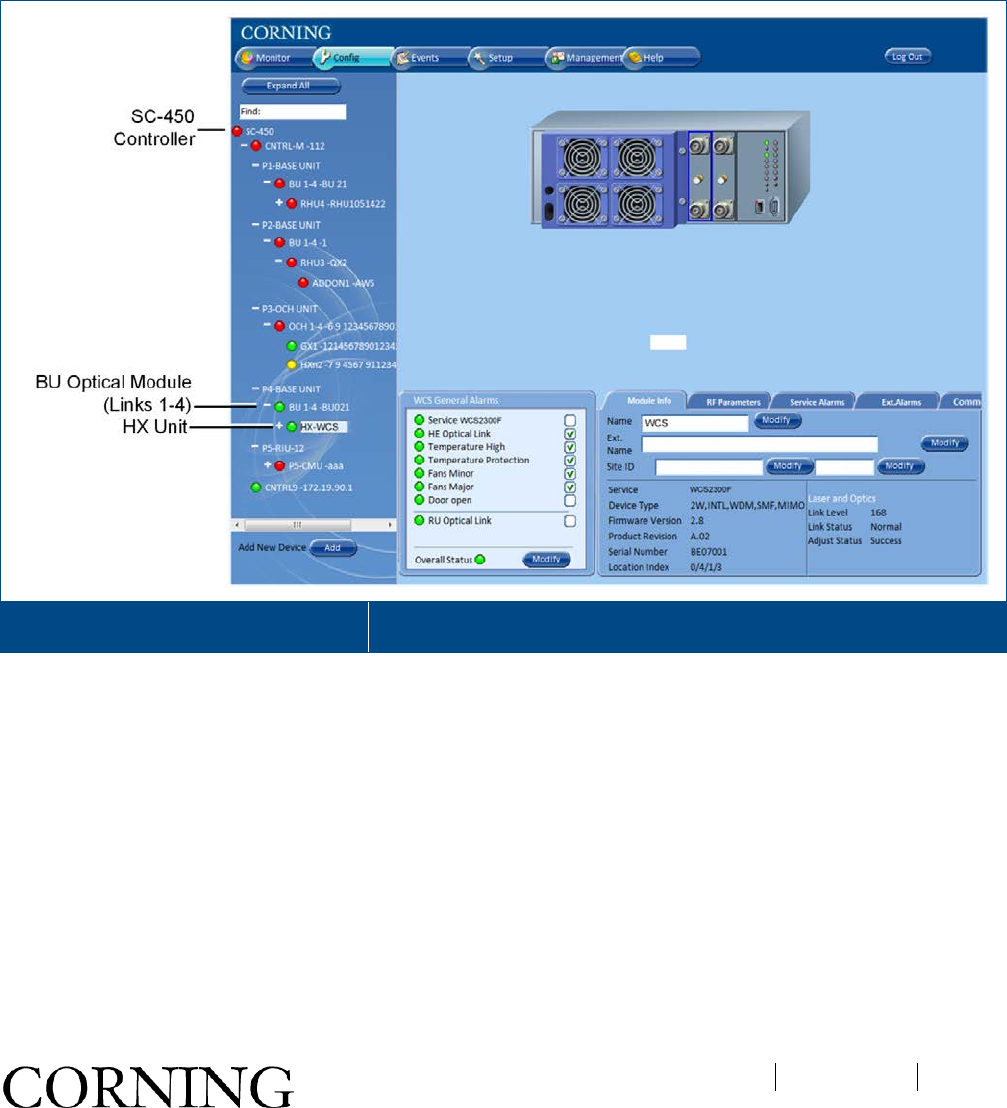
1.3 System Monitoring and Management
The HX WCS remote unit is centrally managed via the SC-450 Controller (v7.2 and higher). Note that HX is not
directly connected to the controller. The HX is managed and configured via the BU to which it is connected
Figure 1-3 shows the Configuration tabs of the selected HX unit. Refer to the SC-450 Controller User Manual
(v7.2 and higher) for information on how to configure and manage the HX WCS remote unit.
Example of HX WCS Configuration Tab Figure 1-3
오류! 지정한 스타일은 사용되지 않습니다.
CMA-TBD-AEN
Page 17
1.4 HX Unit Description
The HX WCS unit consists of the following main modules:
• RCU – Remote Control Unit; Includes status LEDs for each module and control ports
• HX-WCS MUX – Multiplexer [ANT. 1 MUX (right) for SISO; ANT. 2 MUX (left) for MIMO] including interfaces
to RF antennas and to MA1000/MA2000 units; combines signal sources additional external RF signals (when
connected to HX unit and MA1000/MA2000 remote) while providing the proper filtering into a single antenna
port
• HX Module – [ANT. 1 (right) for SISO; ANT. 2 (left) for MIMO] Internal module that interfaces to the optical
converter unit (Base Unit) connects via an SMF pair and supports one service. The HX WCS module
provides the additional amplification on the DL signals routed from the BU towards the Multiplexer.
• Power Supply - DC power; Internal module
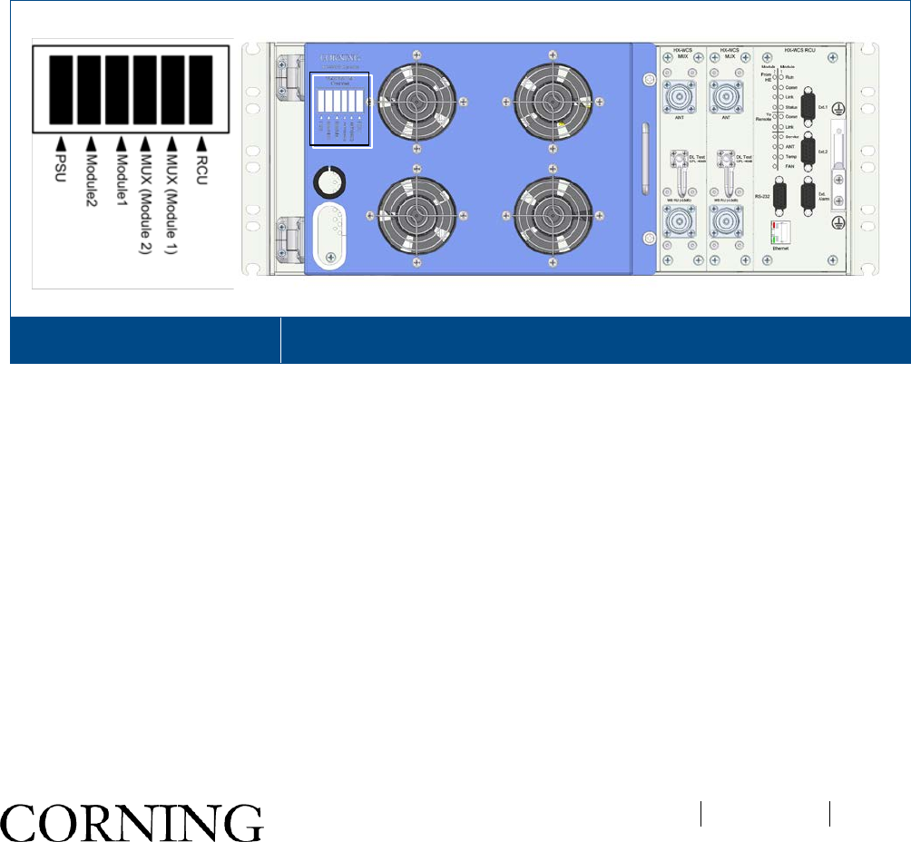
The unit plot plan is provided on the left side of the enclosure door:
HX WCS Unit Plot Plan Figure 1-4
The following sections provide details on the front panel and internal module interfaces.
오류! 지정한 스타일은 사용되지 않습니다.
CMA-TBD-AEN
Page 18
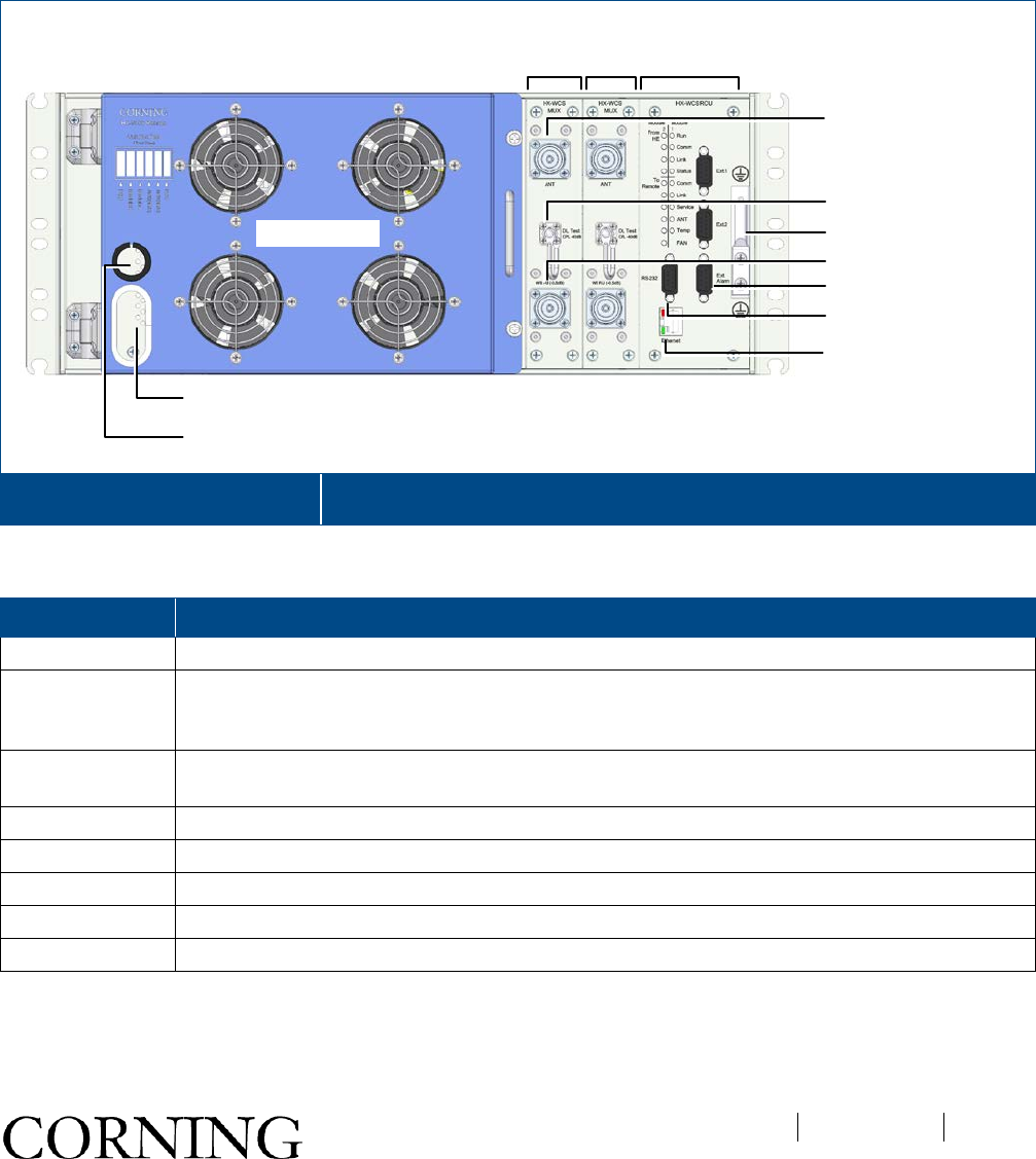
1.4.1 HX WCS External Interfaces
The HX WCS front panel includes the multiplexer interfaces (e.g. antenna port, DL Test port, wideband RU port),
system level status LEDs and service maintenance ports.
Note: Both SISO and MIMO models include two sets of multiplexer RF interfaces. For SISO models, the RF
connections will be performed via the connectors corresponding to the installed HX remote unit module (inside
chassis): Left MUX for Left HX WCS Module and Right MUX for Right HX WCS Module. (See section 1.4.2 for
internal modules.)
HX WCS Front Panel Interfaces Figure 1-5
Table 1-1 provides a description of the front panel connectors.
Connector Description
ANT 4.3-10 Type duplexed antenna port
WB-RU 4.3-10 Type duplexed wideband remote unit expansion port for interfacing to external RF In
source (i.e. HX4 remote) so that additional services are combined with those of the HX and
distributed from the duplexed HX antenna port
DL Test CPL.
Port SMA-Type female 50Ω connector (40 dB ± 2 dB) used for RF DL test
RS-232 D-Type 9 pin female console port used for connecting to engineering GUI
RJ-45 Ethernet connection for local craft
Ext. 1 / Ext. 2 DB-9 female (Future option)
Ext. Alarms
DB-9 female external alarm connector for external dry contact alarm connections
GND Two-hole, standard barrel grounding lug
Table 1-1. HX Front Panel Connectors
Fan Modules
MUX 1
MUX 2
Opening for Routing
Power Cable
Opening for Routing
Fiber
Antenna
DL Test Coupling Port
RS-232 Console
Ethernet
RCU
Grounding Lug
Wideband RU (-0.5dB) Port
External Alarms Port
오류! 지정한 스타일은 사용되지 않습니다.
CMA-TBD-AEN
Page 19
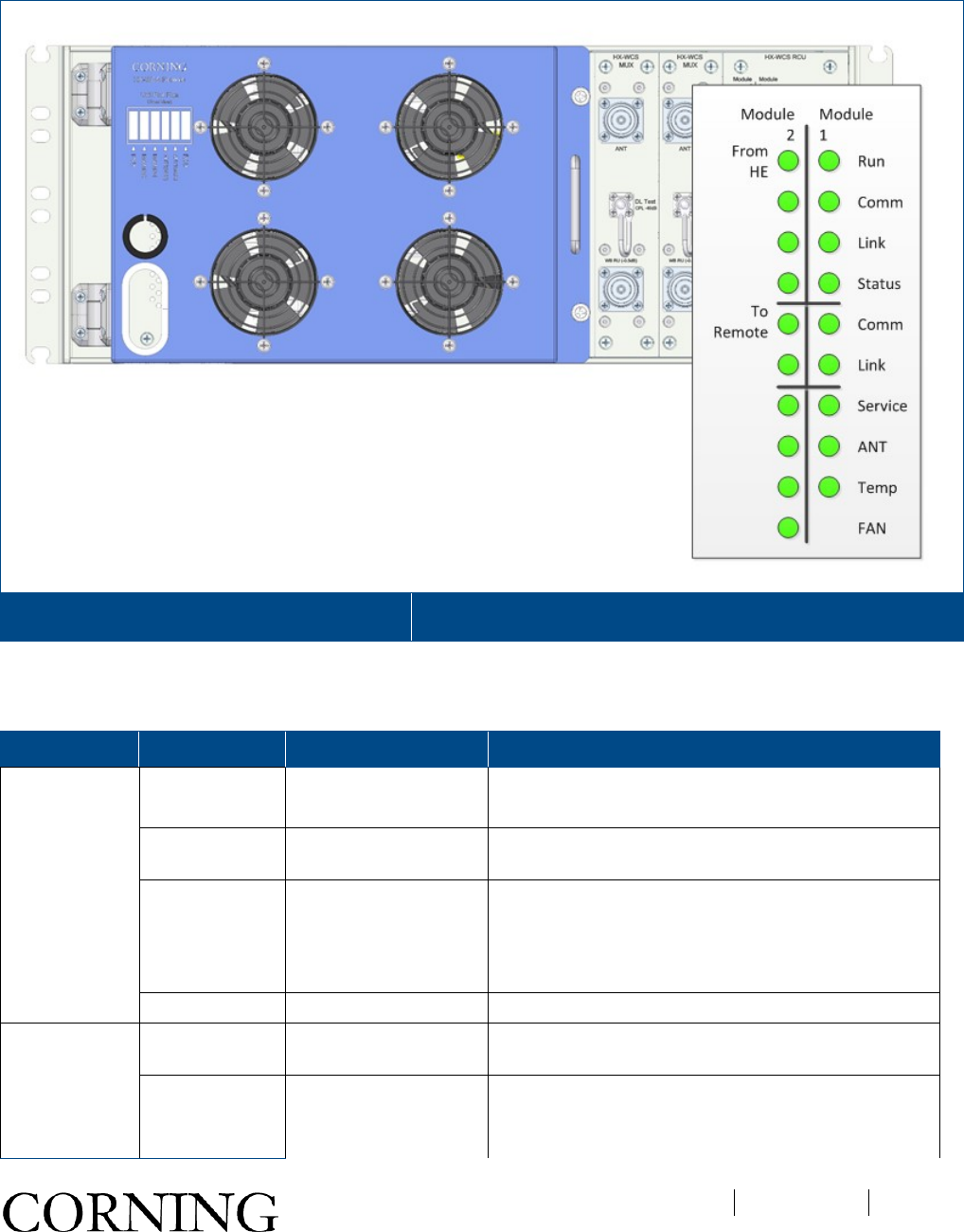
Refer to Figure 1-6 and Table 1-2 for description of HX status LEDs.
HX WCS RCU Module Status LEDs Figure 1-6
Note: Module 1 and Module 2 LEDs correspond to installed modules [Module 1 for ANT. 1 (SISO); Module 2 for
ANT. 2 (MIMO)].
LED State Description
From HE
(from
headend)
Run Blinking green
Off
Power input detected
Unit powered off
Comm Green Short blink upon receiving FSK message
(Off at any other time)
Link Steady green Optical link level is above normal threshold
Blinking green Optical link level is lower than Normal threshold but
above no-link threshold
Off Optical link level is below No link threshold
Status Green / Yellow / Red Color according to device’s overall status
To Remote Comm Green Short blink upon receiving FSK message
(Off at any other time)
Link Steady green Optical link level is above normal threshold
Blinking green Optical link level is lower than Normal threshold but
above no-link threshold
오류! 지정한 스타일은 사용되지 않습니다.
CMA-TBD-AEN
Page 20
LED State Description
Off Optical link level is below No link threshold
LED State Description
Device
Service
Green
Service status is ok
Red
Any service alarm is set
Ant.
Green
VSWR alarm is clear
Red
VSWR alarm is set
Temp.
Green
Over Temp and Temperature Protection alarms are
clear
Red
Over Temp or Temperature Protection alarms is
set
Fan
Green
Fan alarm is clear
Yellow
Fan alarm is set (minor) for first fan faulty
Red
Fan alarm is set (major) for other fan faulty.
Table 1-2. HX WCS RCU Status LED Descriptions
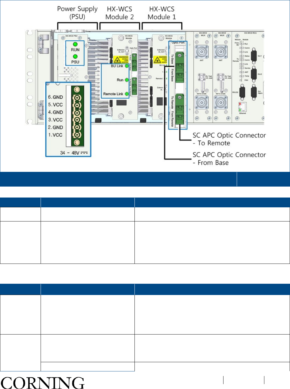
1.4.2 Internal Module Interfaces
The HX internal modules include two main modules (see Figure 1-7):
• PSU – Power supply module; includes DC In connector and status LEDs
• HX Module – one for SISO cabinets and two for MIMO (the interfaces are the same for each module);
comprises an optical module and power amplifier; interfaces to the base unit; Left HX Module corresponds to
left HX MUX.
오류! 지정한 스타일은 사용되지 않습니다.
CMA-TBD-AEN
Page 21
HX (MIMO) Internal Modules – PSU (Left) and HX WCS Modules (Middle and Right) Figure 1-7
Module Interface Description
PSU Power connector 34-48 V DC input; 6 pin DC terminal block connector
HX Module Optic Port (SC APC fiber-optic pair connector; SMF; connection
towards Base Unit (BU)
(SC APC fiber-optic pair connector; SMF; connection
towards additional remote unit
Extension UL/DL SMA type (future option)
Table 1-3. HX WCS Internal Module Connectors
Module LED Description
PSU Run Steady green – required power input detected
Off – no power input
PSU Off – normal operation
Steady red – faulty PSU module; In more than 10%
difference than the rated DC output, the red LED occurs.
HX-WCS
Module BU Link Off – No optical link
Blinking green – Low optical link level
Steady green – Normal optical link level
Run Off – no power input

오류! 지정한 스타일은 사용되지 않습니다.
CMA-TBD-AEN
Page 22
Module LED Description
Blinking green – power input detected
Remote Link
Note: Indicates link status
between HX WCS and additional
remote unit connected.
Off – No optical link
Blinking green – Low optical link level
Steady green on – Normal optical link level
Table 1-4. HX WCS Internal Module LEDs
오류! 지정한 스타일은 사용되지 않습니다.
CMA-TBD-AEN
Page 23
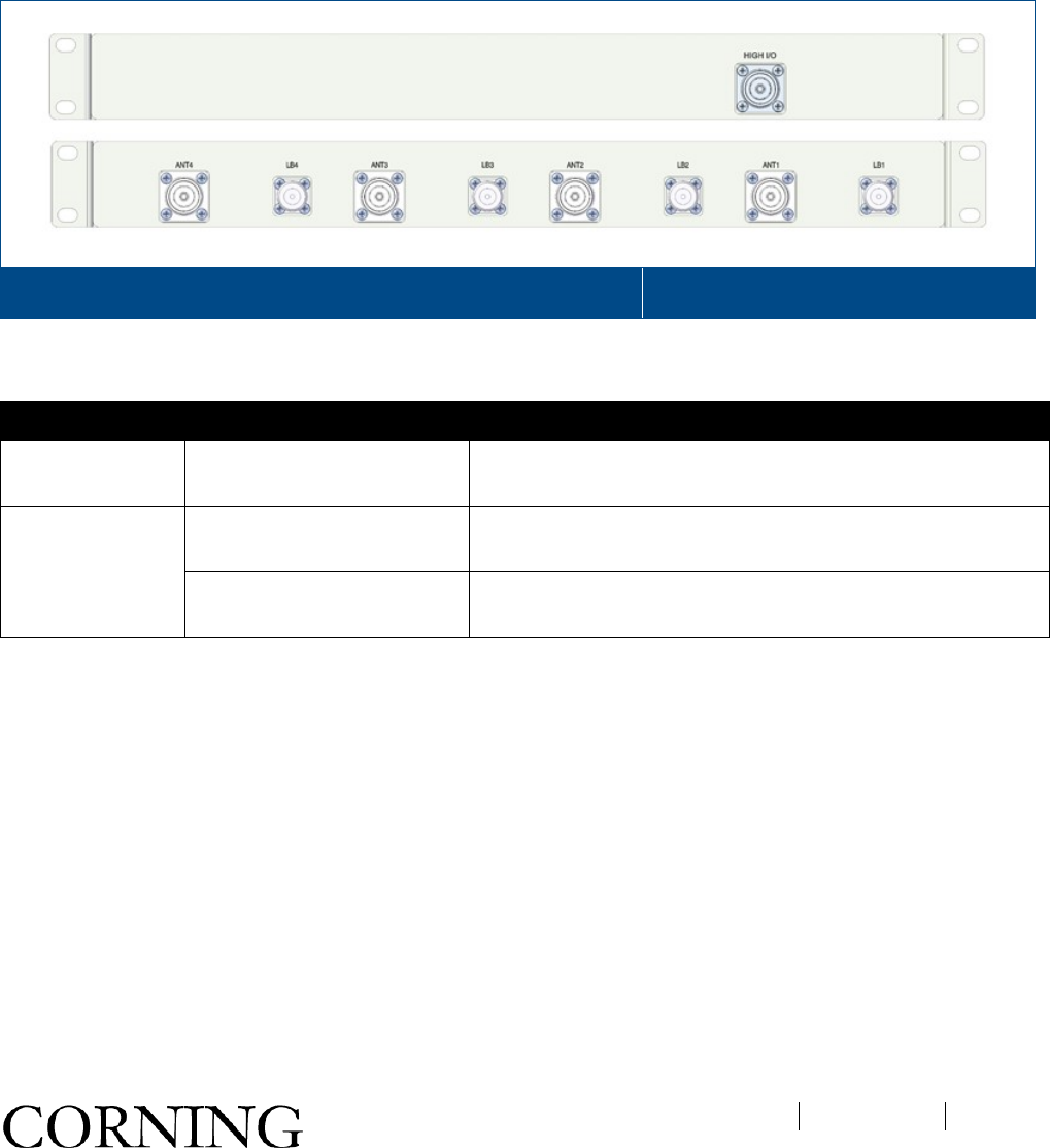
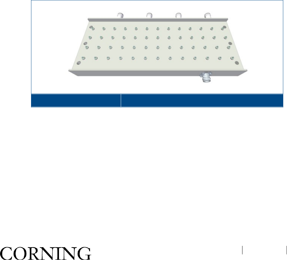
1.5 External Passive Module (EPM)
The External Passive Module (EPM) is required when in installations with an existing MA1000/MA2000 remote
unit (e.g. MA2000 QX). The EPM is used to combine up to four low band output wideband signals with the high
band HX WCS output signal. The module includes a 1:4 splitter for the high band (i.e. WCS) and four internal
diplexers that combine the 2.3 GHz signal with the wideband signal received from the MA1000/MA2000 remote.
The EPM interfaces to the HX WCS and to the service combiner unit (SCU) of the MA1000/MA2000 remote.
External Passive Module – Front (Top) and Rear (Bottom) Panels Figure 1-8
Refer to Table 1-5 for a description of the EPM interfaces.
Panel Connector Description
Front HIGH I/O One Mini DIN 4.3-10 high-band input port interfaces to HX-
WCS
Rear ANT Four Mini DIN 4.3-10 combined output ports interface to
wideband antennas
LB Four N-Type low-
band input ports interface to service
combiner unit (SCU) on MA1000/MA2000.
Table 1-5. EPM Front and Rear Panel Interfaces

오류! 지정한 스타일은 사용되지 않습니다.
CMA-318-AEN
Page 24
• Installation Guidelines
This chapter describes the installation procedure for the HX WCS remote unit.
1.6 Site Considerations
• The distance between the HX service antenna and the coverage area should correspond to LOS (Line of
Sight) requirements for maximum coverage area.
• The maximum fiber path loss is 3 dB.
• The system delay of the optical system must be taken into consideration when there are neighboring BTS
sites overlapping in coverage.
1.7 Environmental
Humidity has an adverse effect on the reliability of the equipment. It is recommended to install the equipment in
locations having stable temperature and unrestricted air-flow.
The installation location for the system should be well ventilated. The equipment has been designed to operate at
the temperature range and humidity level as stated in the product specifications with a relative humidity of max.
90% and temperatures range of -40 to 65oC (-40° to 149°F).
1.8 Installation Requirements
• Mounting surface shall be capable of supporting the weight of the equipment.
• In order to avoid electromagnetic interference, a proper mounting location must be selected to minimize
interference from electromagnetic sources such as large electrical equipment.
• Working space available for installation and maintenance for each mounting arrangement. Ensure
unrestricted airflow.
• Ensure grounding connector is within reach of the ground wire.
• Ensure a power source is within reach of the power cord and the power source has sufficient capacity.
• Where appropriate, ensure unused RF connectors are terminated.
• Do not locate the equipment near large transformers or motors that may cause electromagnetic interference.
• Reduce signal loss in feeder cable by minimizing the length and number of RF connections.
• Ensure the equipment will be operated within the stated environment (refer to datasheet).
• Where appropriate, confirm available of suitably terminated grade of RF and optical fiber.
• Observe handling of all cables to prevent damage.
오류! 지정한 스타일은 사용되지 않습니다.
CMA-TBD-AEN
Page 25
1.9 Fiber Optic Requirements
1.9.1 Authorized Optic Cables
• Only single mode fiber can be used with HX WCS product
• All fiber in a given length of fiber must be of the same core diameter.
• All bulkhead adapters must be single mode SC APC (Green) adapters.
• All terminations, cross connections or patches must be direct fusion splice or Corning specified patch cords
listed below.
900 microns pathcord for splicing, 2 Meters, 2xSC/APC
Diamond p/n ENC/1045341 Beige boots, 62.5/125/900 MA# 500001057
Diamond p/n ENC/1045340 Black boots, 50/125/900 MA# 500001058
Zipcord patchcord, 4xSC/APC, 50/125/900/2000/4500 micron
Diamond p/n ENC/1045342 Black/Brown boots, 1 Meter MA# 50000105
Diamond p/n ENC/1045343 Black/Brown boots, 3 Meter MA# 500001060
Zipcord patchcord, 4xSC/APC, 62.5/125/900/2000/4500 micron
Diamond p/n ENC/1045344 Beige/Brown boots, 1 Meter MA# 500001061
Diamond p/n ENC/1045345 Beige/Brown boots, 3 Meter MA# 500001062
1.9.2 Fiber Optic Rules
ATTENTION!
Please also refer to the laser safety section in the document preface.
• Fiber optic cables require proper handling. Do not stretch, puncture, or crush the fiber cable(s) with staples,
heavy equipment, doors, etc.
• Always maintain the minimum bending radius specified by the cable manufacturer. The minimum bend radius
is usually 10 times the cable's outer diameter. In the case of single optical fiber that is not in a cable, the
minimum bending radius to be observed is 30 mm.
• Use SC APC connectors (green color) 8 deg only.
• Pay special attention while connecting the SC APC connectors - ensure that you hear a “click”, indicating a
secure connection
• Use minimum splicing/connectors to achieve minimum losses on the fibers.
• Use precaution while installing, bending, or connecting fiber optic cables.
• Use an optical power meter and OTDR for checking the fiber optic cables.
• Make sure the environment is clean while connecting/splicing fiber optic cables.
• All fiber optic connectors should be cleaned prior to connecting to the system
• Fiber connector protective caps should be installed on all non-terminated fibers and removed just before they
are terminated.
• Check the fiber optic connections.

오류! 지정한 스타일은 사용되지 않습니다.
CMA-TBD-AEN
Page 26
• Never look directly into the end of a fiber that may be carrying laser light. Laser light can be invisible and can
damage your eyes.
1.10 RF Coaxial Cable Guidelines
1.10.1 General Cable Installation Procedures
Note: The installer should be familiar with the ANSI/TIA/EIS-568 Cabling Standard guidelines.
Observe the general cable installation procedures that meet with the building codes in your area. The building
code requires that all cabling be installed above ceiling level (where applicable). The length of cable from the
risers to each antenna may need to be concealed above the ceiling.
The cable must be properly supported and maintained straight using velcro cable ties, cable trays and clamps or
hangers every 10 feet (where practical above ceiling level). Where this is not practical, the following should be
observed:
• The minimum bending radius of the supplied ½” coax cable should be 7”.
• Cable that is kinked or has a bending radius smaller than 7” must be replaced.
• Cable runs that span less than two floors should be secured to suitably located mechanical structures.
• The cables should be supported only from the building structure.
• All cables shall be weather-resistant type.
• Cable length - determined by the system installation plan. When calculating the cable length, take into
account excess cable slack so as not to limit the insertion paths.
1.10.2 RF Rules
• Use coax RG-223, 50 ohm, for RF connections between HX units and DAS antennas.
• When using the Corning system in an environment in which other indoor coverage systems are installed, it is
recommended (where possible) that the antennas are placed at least two meters apart
• When bending coax cables, verify that the bending radius does not exceed the coax specifications.
• Use wideband antennas supporting a range of 700 MHz to 2600 MHz
• Terminate all unused HX RF ports with a 50 ohm load
• Make sure that the VSWR measured at the coax cable meets the product specification The VSWR must be
measured prior to terminating the HX RF ports in the remote communication rooms.
1.10.3 Coax Cable Lengths and Losses
Use the compatible jumper to connect the coax connector to the external antenna.
Note: The required distance between the antennas (installed in the ceiling) depends on the infrastructure and
calculated path-loss.
Coax
Length Coax Loss
(900 MHz)
Connector
Loss Total Loss
30 0.7 1.5 2.2
40 0.9 1.5 2.4
50 1.1 1.5 2.6
오류! 지정한 스타일은 사용되지 않습니다.
CMA-TBD-AEN
Page 27
Coax
Length Coax Loss
(900 MHz)
Connector
Loss Total Loss
60 1.3 1.5 2.8
70 1.5 1.5 3
80 1.7 1.5 3.2
90 1.9 1.5 3.4
100 2.1 1.5 3.6
110 2.3 1.5 3.8
120 2.5 1.5 4
130 2.7 1.5 4.2
140 2.9 1.5 4.4
150 3.1 1.5 4.6
160 3.3 1.5 4.8
170 3.5 1.5 5
180 3.7 1.5 5.2
190 3.9 1.5 5.4
200 4.1 1.5 5.6
Table 2-6. Typical Coax Cable Lengths and Losses
1.10.4 Cable Routing
Ensure all cables, e.g. power cable, feeder cable, optic fiber, commissioning cable, connecting are properly
routed and secured so that they are not damaged.
1.11 Antenna Specifications and Guidelines
Determine the antenna installation configuration, according to the transmission and coverage requirements and
the installation site conditions.
1.11.1 Authorized Antennas and Couplers
• External antennas - No limitation on any vendor of available external antennas with respect to the following
requirements:
• Omni Directional or Directional
• Supported frequency range: wideband antennas supporting a range of 700 MHz to 2600 MHz
• Gain: up to 12.5 dBi
• Impedance: 50 Ohm
• Types of couplers/splitters – depends on number of splits
• Couplers – Use N-Male to N-Female broadband coupler separately ordered from Corning (P/N AK-
1COUPLER-NM-NF) or the equivalent:

오류! 지정한 스타일은 사용되지 않습니다.
CMA-TBD-AEN
Page 28
• Broadband frequency: 698 – 2700 MHz
• -40 dB coupling (QMA coupling port)
• Max. VSWR/Return Loss: 5:1 / 16 dB
• Max. Insertion Loss (dB): 0.2
• Impedance: 50 ohms
1.11.2 General Antenna Installation Guidelines
• The wideband antenna should be installed at a convenient location, free of metallic obstruction (can also be
installed in plenum spaces).
• Install the connected antenna at the designated height and tune it roughly toward the Service coverage area.
• Each individual antenna used for this transmitter must be installed to provide the separation distance as
specified in the FCC grant from all persons during normal operation and must not be co-located with any
other antenna for meeting RF exposure requirements
1.12 Grounding Requirement
Verify that the equipment has been well grounded (refer to the grounding lug on the bottom right corner of the HX
WCS front panel). This includes antennas and all cables connected to the system. Ensure lightning protection for
the antennas is properly grounded. Also, see section 3.3.2.
1.13 Manual Handling
During transportation and installation, take necessary handling precautions to avoid potential physical injury to the
installation personnel and the equipment.
1.14 Installation Requirements
• Working space available for installation and maintenance for each mounting arrangement. Ensure
unrestricted airflow.
• Ensure grounding connector is within reach of the ground wire.
• Ensure a power source is within reach of the power cord and the power source has sufficient capacity.
• Where appropriate, ensure unused RF connectors are terminated.
• Do not locate the equipment near large transformers or motors that may cause electromagnetic interference.
• Reduce signal loss in feeder cable by minimizing the length and number of RF connections.
• Ensure the equipment will be operated within the stated environment (Appendix A: System Specifications).
• Where appropriate, confirm available of suitably terminated grade of RF and optical fiber.
• Observe handling of all cables to prevent damage.
오류! 지정한 스타일은 사용되지 않습니다.
CMA-TBD-AEN
Page 29
• HX Physical Installation
This chapter describes the mounting procedure and physical connections for the HX WCS Remote Unit.
1.15 Unpacking and Inspection
Unpack and inspect the cartons according to the following procedure
1. Open the shipping carton and carefully unpack each unit from the protective packing material.
2. Verify that all of the item required for installing the HX WCS have been received (refer to Table 3-1). If any
of the listed items are missing, contact your Corning representative.
3. Check for signs of external damage. If there is any damage, call your Corning service representative.
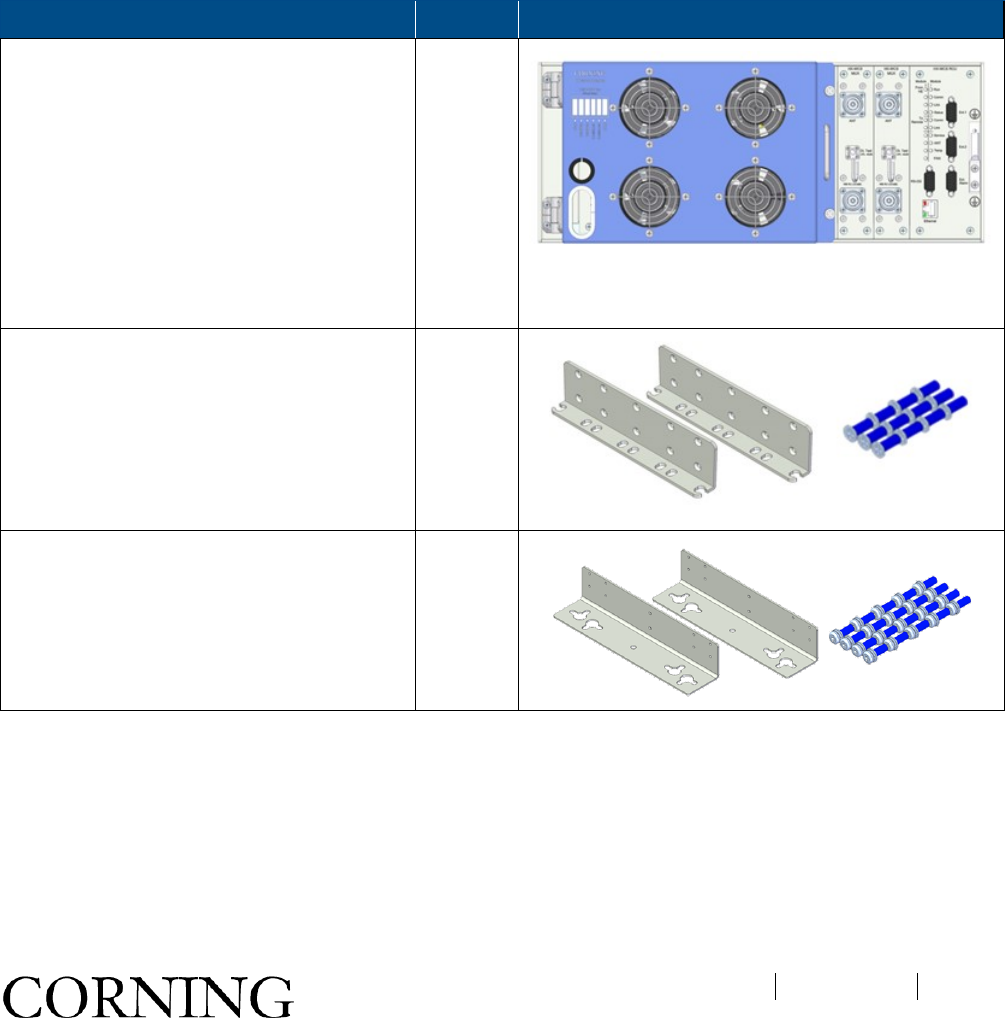
HX Kit Item Quantity
HX WCS Remote Unit:
• HX-WCS-SISO-NU*
• HX-WCS-SISO-PLUS*
• HX-WCS-MIMO**
*SISO models include one HX-WCS Module
and one slot cover (blank panel for
unoccupied HX-WCS Module
**MIMO slot) ; MIMO models include two
HX-WCS Modules
1
19-in rack brackets (factory assembled) –
(default mounting option) for rack-mount
installations
2
(RT/LT)
Flat Head Screw UNC 6-32, 8mm; Stainless
Steel 12
Wall Mount Bracket (Belly-to-Wall)
Assembly: Bracket
2
(RT/LT)
Pan Head Screw Sems UNC 6-32, 11 mm;
Stainless Steel; Used for securing bracket to
HX sides
20
Table 3-7. HX WCS Package Items List

오류! 지정한 스타일은 사용되지 않습니다.
CMA-TBD-AEN
Page 30
1.16 Mounting
The HX WCS unit is installed in the communication room via one of the following options (each type of installation
requires a different pair of brackets):
• Rack mount - rack ears preassembled
• Vertical wall mount (i.e. Belly-to-Wall; cabinet door faces side)
• (Optional) Horizontal - (i.e. Back-to-Wall; cabinet door faces front); separately ordered kit: AK-HX-ADDON-
B2W-MNT
1.16.1 General Instructions
• HX WCS remotes should be installed in a communication room that provides access only to authorized
personnel.
• The units are maintenance free. In the event of failure, only authorized personnel should handle the units.
• Only trained and qualified personnel should be allowed to install or replace this equipment.
• Verify that ambient temperature of the environment does not exceed 65°C (149°F)
1.16.2 Rack Mount Installation
1.16.2.1 Rack Installation General Safety Instructions
Review the following guidelines to help ensure your safety and protect the equipment from damage during the
installation.
• To maintain a low center of gravity, ensure that heavier equipment is installed near the bottom of the rack and
load the rack from the bottom to the top.
• Ensure that adequate airflow and ventilation within the rack and around the installed components so that the
safety of the equipment is not compromised.
오류! 지정한 스타일은 사용되지 않습니다.
CMA-TBD-AEN
Page 31
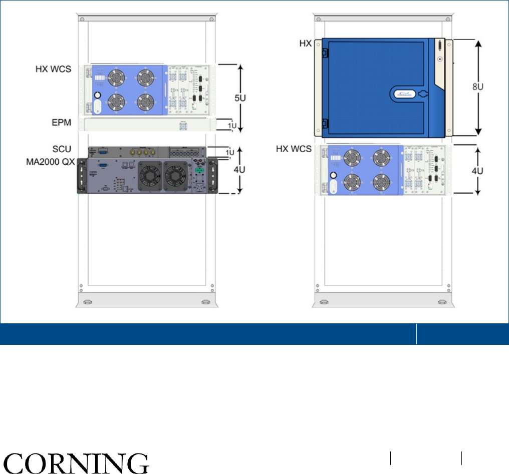
1.16.2.2 Mounting HX WCS in 19-in Rack
Note the following:
• The HX WCS requires 4U rack height availability
• If the HX WCS unit is to be installed with an existing MA1000/MA2000 remote the EPM (1U) should be
installed in between the remote units in order to facilitate the connections
• Rack nuts and screws not provided (depend on rack type)
To mount the HX WCS in a 19-in rack:
1. Determine the location of the HX WCS in the rack.
2. Secure the unit to the communication racks’ vertical uprights via at least two bracket holes on each side
(one top and one middle) using the appropriate rack nuts and screws.
Refer to Figure 3-1 and Figure 3-3 for examples of rack installations.
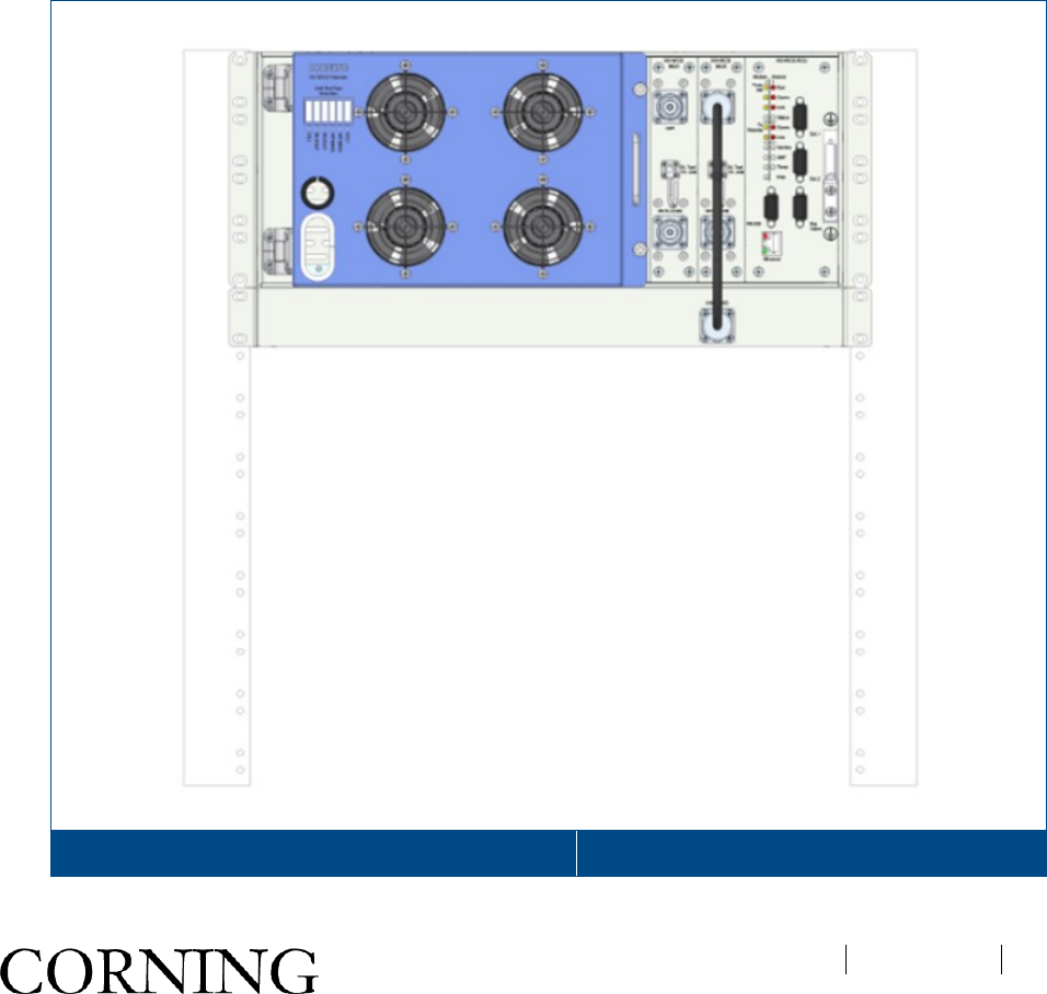
Examples of HX WCS Rack Installations with Additional HX and MA2000 QX Remote Units
Figure 3-9
오류! 지정한 스타일은 사용되지 않습니다.
CMA-TBD-AEN
Page 32
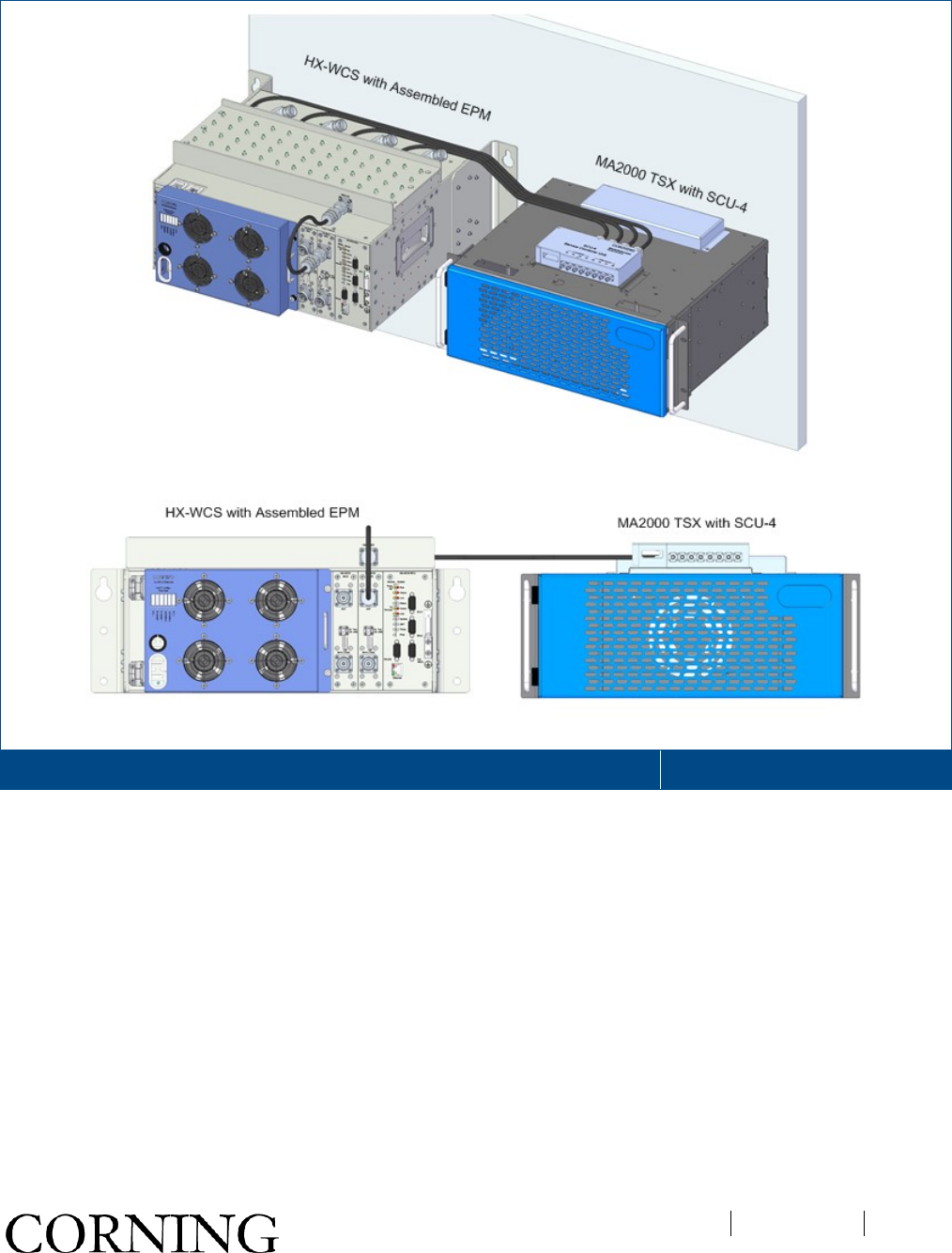
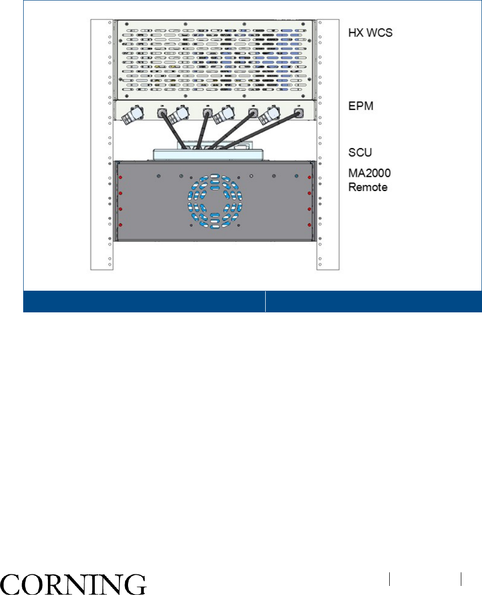
Examples of HX WCS Rack Installations with Additional MA2000 TSX Remote Units Figure 3-10
오류! 지정한 스타일은 사용되지 않습니다.
CMA-TBD-AEN
Page 33
1.16.3 Wall-Mount Installation
IMPORTANT! The wall-mount installation procedures in this section are for concrete/brick walls. For other wall
types, installer is responsible for following standard practices using the appropriate tools and materials.
The following sections provide instructions for both vertical (“belly-to-wall”) and horizontal (optional “back-to wall”)
wall-mount installation types.
Note the following:
• If the HX WCS is to be installed in conjunction with the EPM, the latter must be assembled to the HX unit
before mounting the HX on the wall. Refer to 3.2.3.1.
• When selecting the installation location, make sure that there is enough clearance distance from the bottom
to open the HX WCS chassis door.
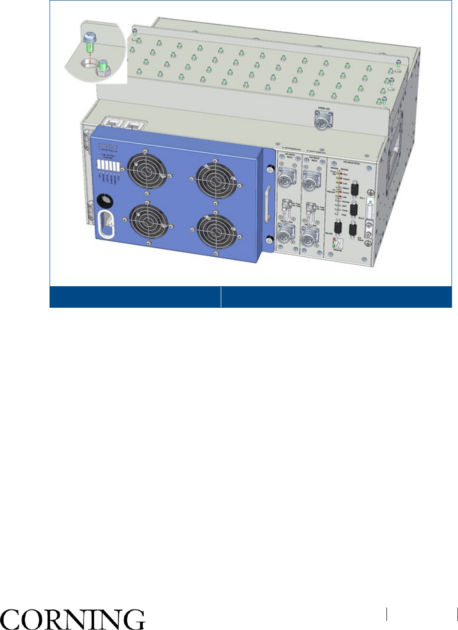
1.16.3.1 Assembling EPM to HX WCS (for Configurations with EPM)
To assemble EPM onto HX WCS
1. Remove the factory assembled rack ears from the sides of the unit.
2. Fixed hole is at the top of the EPM unit for wall mounting. See Figure 3-3.
Assembling Brackets to EPM Figure 3-11
오류! 지정한 스타일은 사용되지 않습니다.
CMA-TBD-AEN
Page 34
3. Place the EPM onto the top of the HX WCS unit and using six UNC 6-32, 11mm screws, assemble the
EPM onto the top sides of the HX WCS unit for top side. See Figure 3-4.
Assembling EPM onto HX WCS Figure 3-12
1.16.3.2 Horizontal Wall Mount Installation
Additional required tools and materials
• Philips/electric screwdriver
• Four anchors for mounting brackets on wall (anchor type depends on surface type)
To mount the HX WCS unit on the wall:
1. Remove the factory assembled rack brackets from the sides of the HX WCS unit.
2. Using ten UNC 6-32, 11 mm screws for each bracket (provided in HX kit), assemble the wall-mount
brackets to the sides of the HX WCS as shown in Figure 3-5.
오류! 지정한 스타일은 사용되지 않습니다.
CMA-TBD-AEN
Page 35
Wall-Mount Bracket Assembly Figure 3-13
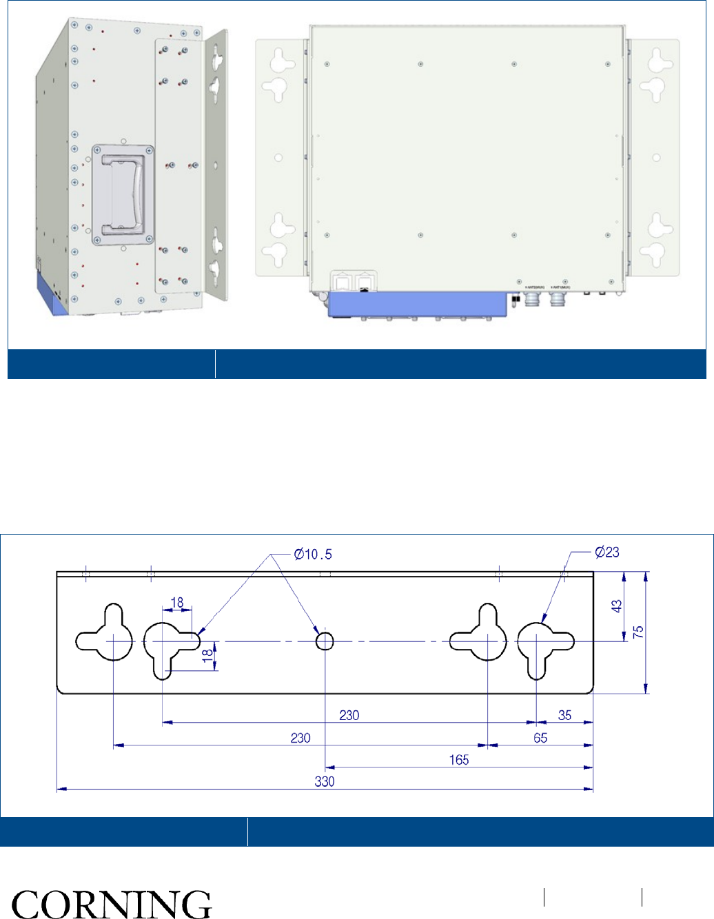
3. Referring to bracket hole dimensions in Figure 3-6 (units in mm), prepare the appropriate anchors and
mount as follows:
• Mark four holes (minimum of two on per bracket) on the wall for drilling the anchors
• Drill four holes, using a hammer drill.
• Fill the holes with silicon to help weather-proof the drilled holes and to prevent erosion.
• Tap in expanding lead shield anchors
Wall-Mount Bracket Hole Dimensions Figure 3-14
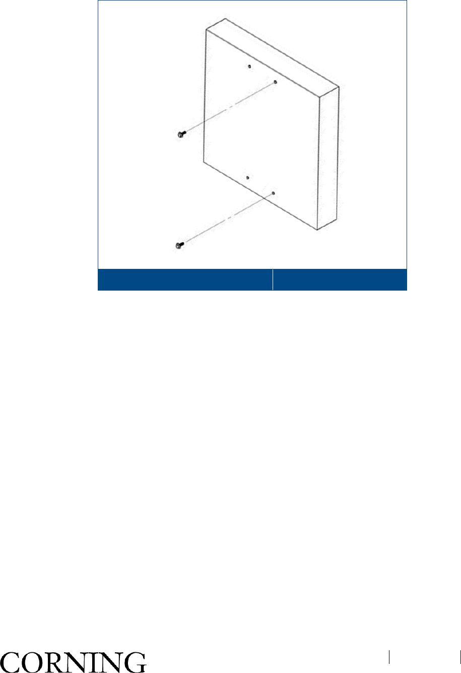
4. Insert two bolts in top anchors and tighten until bolt head is 0.5” from surface of wall. See Figure 3-7.
오류! 지정한 스타일은 사용되지 않습니다.
CMA-TBD-AEN
Page 36
Inserting First two Bolts in Anchors Figure 3-15
5. Hang the unit and bracket assembly onto the two bolts using the key holes.
6. Insert remaining bolts (two on each side) through remaining bracket holes into anchor.
7. Tighten all four bolts.
8. Verify that HX unit is tightly secured and does not shake.
Refer to Figure 3-8 for HX WCS wallmount examples with additional MA2000 remote.
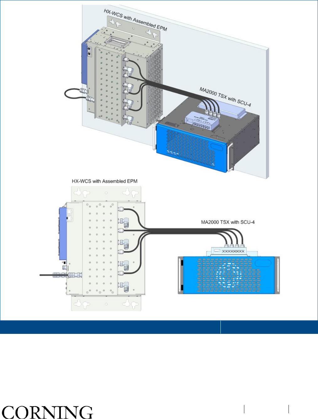
오류! 지정한 스타일은 사용되지 않습니다.
CMA-TBD-AEN
Page 37
Example of HX WCS with Assembled EPM Alongside MA2000 TSX Remote Figure 3-16
오류! 지정한 스타일은 사용되지 않습니다.
CMA-TBD-AEN
Page 38
1.16.3.3 Vertical Wall Mount Installation
The vertical wall-mount brackets are optional and ordered separately.
Unpack and inspect the carton as follows:
1. Open the shipping carton and carefully unpack each unit from the protective packing material.
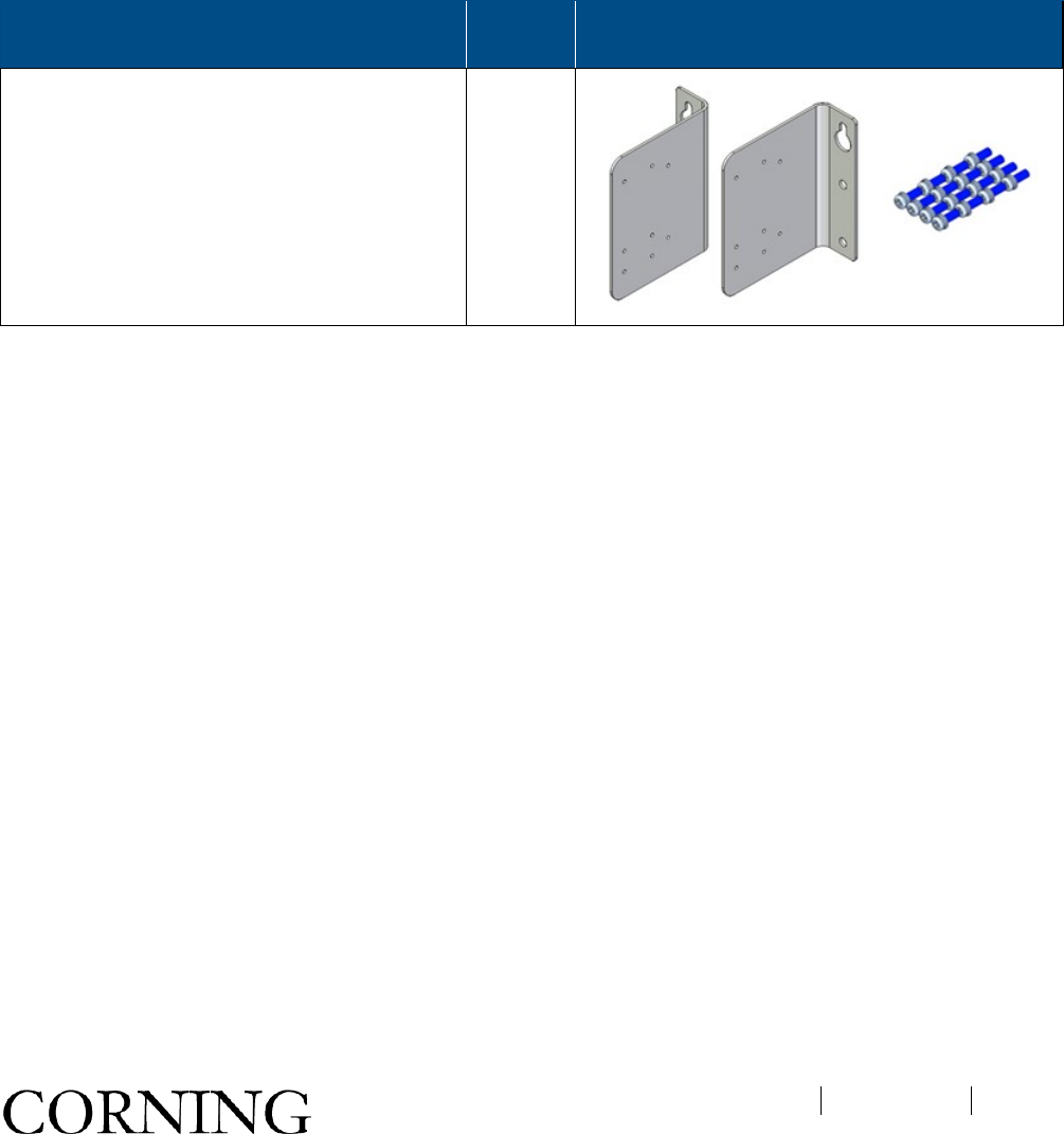
2. Verify that all of the items required for wall mount installation have been received (refer to Table 3-2). If
any of the listed items are missing, contact your Corning representative.
3. Check for signs of external damage. If there is any damage, call your Corning service representative.
Wall Mount Bracket (Back-to-Wall)
Assembly Kit Quantity
Bracket
2
(RT/LT)
Pan Head Screw Sems UNC 6-32, 11 mm;
Stainless Steel; Used for securing bracket to
HX sides
16
Table 3-8. HX WCS Wall-Mount Brackets Package Items List
Additional required tools and materials
• Philips/electric screwdriver
• Hammer drill
• Two anchors for hanging brackets on wall (anchor type depends on surface type) and four bolts for secure
installation
오류! 지정한 스타일은 사용되지 않습니다.
CMA-TBD-AEN
Page 39
To mount the HX WCS unit on the wall:
1. Remove the factory assembled rack brackets from the sides of the HX WCS unit.
2. Using eight UNC 6-32, 11 mm screws for each bracket (provided in HX kit), assemble the wall-mount
brackets to the rear of the HX WCS side panels.
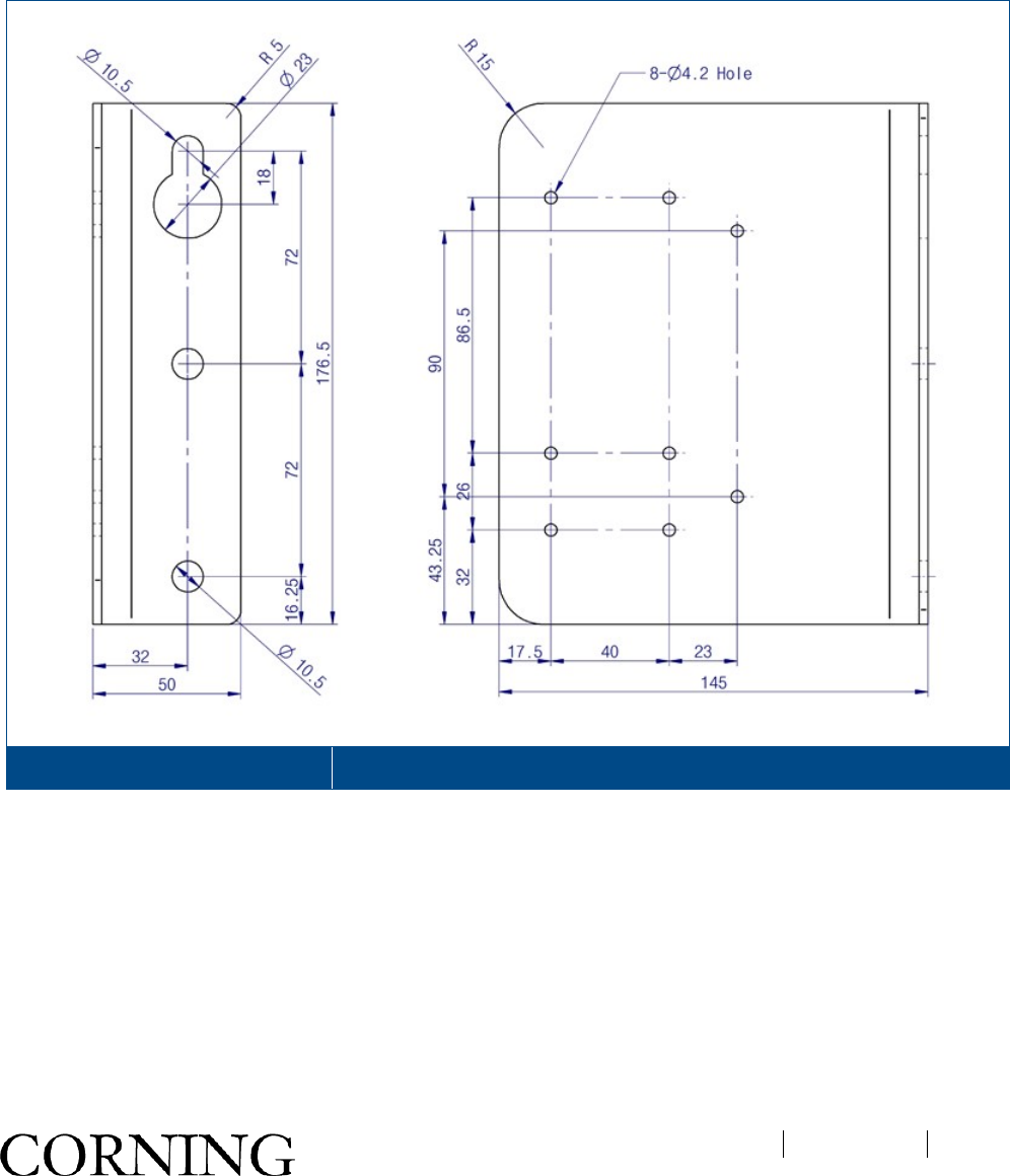
3. Referring to Figure 3-9, prepare appropriate anchors and bolts for drilling.
Wall-Mount Bracket Dimensions Figure 3-17
4. Using bracket holes as a template, mark holes for drilling in wall.
오류! 지정한 스타일은 사용되지 않습니다.
CMA-TBD-AEN
Page 40
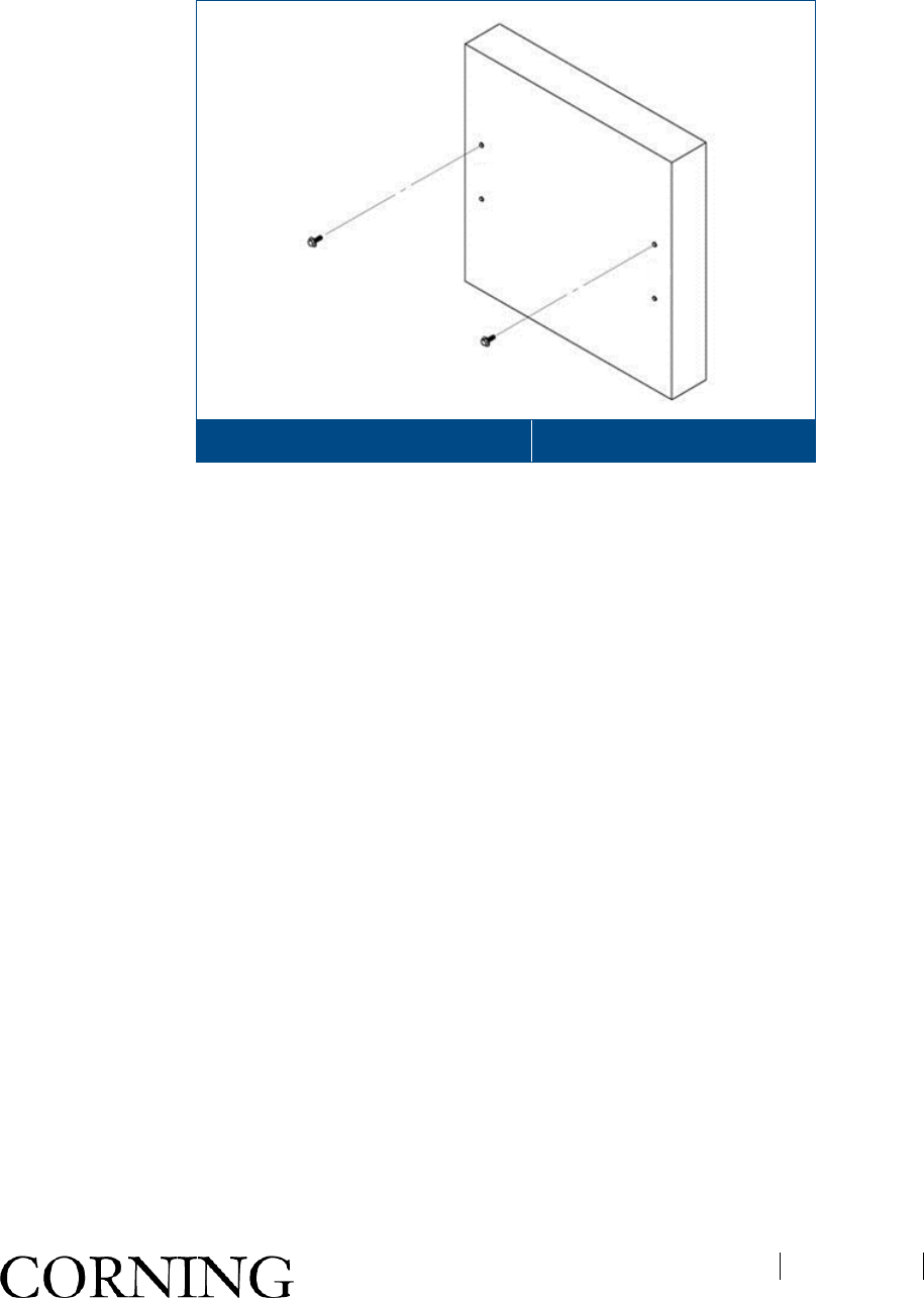
5. Insert two bolts in top anchors and tighten until bolt head is 0.5” from surface of wall. See Figure 3-10.
Inserting First two Bolts in Anchors Figure 3-18
6. Hang the unit and bracket assembly onto the two bolts using the key holes.
7. Insert remaining bolts (two on each side) through remaining bracket holes into anchor and tighten.
8. Verify that HX WCS unit is tightly secured and does not shake.
Refer to Figure 3-11 for HX WCS wall mount examples with additional MA2000 remote.
오류! 지정한 스타일은 사용되지 않습니다.
CMA-TBD-AEN
Page 41
Example of HX WCS with Assembled EPM Alongside MA2000 TSX Remote Figure 3-19
오류! 지정한 스타일은 사용되지 않습니다.
CMA-TBD-AEN
Page 42
1.17 Connections
Note that the HX WCS is an upgrade unit and as such the RF and fiber connections also interface the existing
MA1000/MA2000 remote units. Where relevant, the RF and fiber connections reference existing HX and MA2000
QX as examples of connections to existing remotes.
1.17.1 RF and Fiber Connections
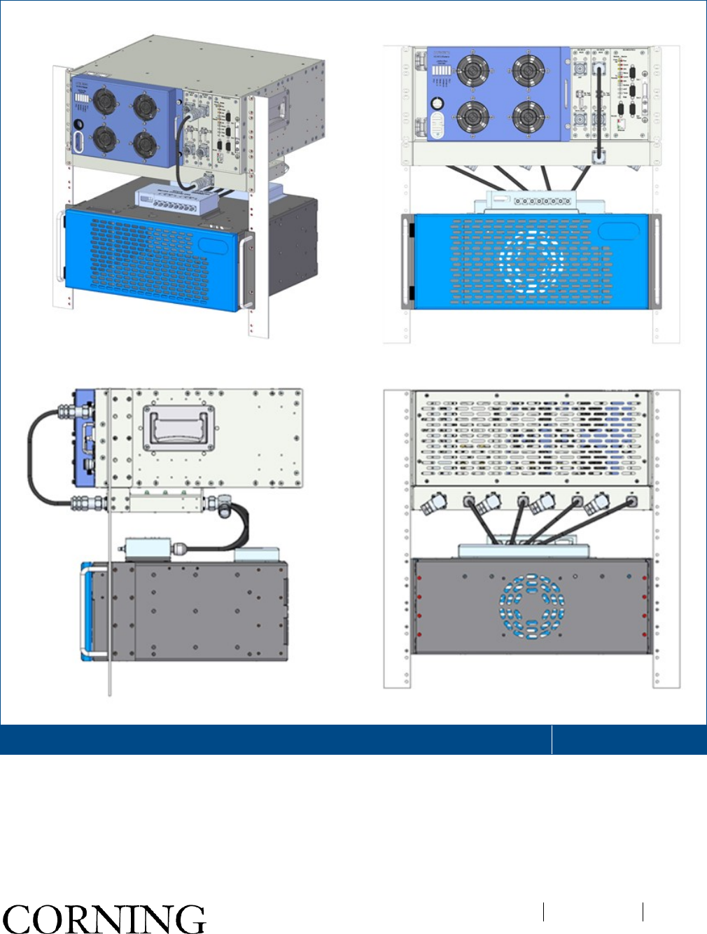
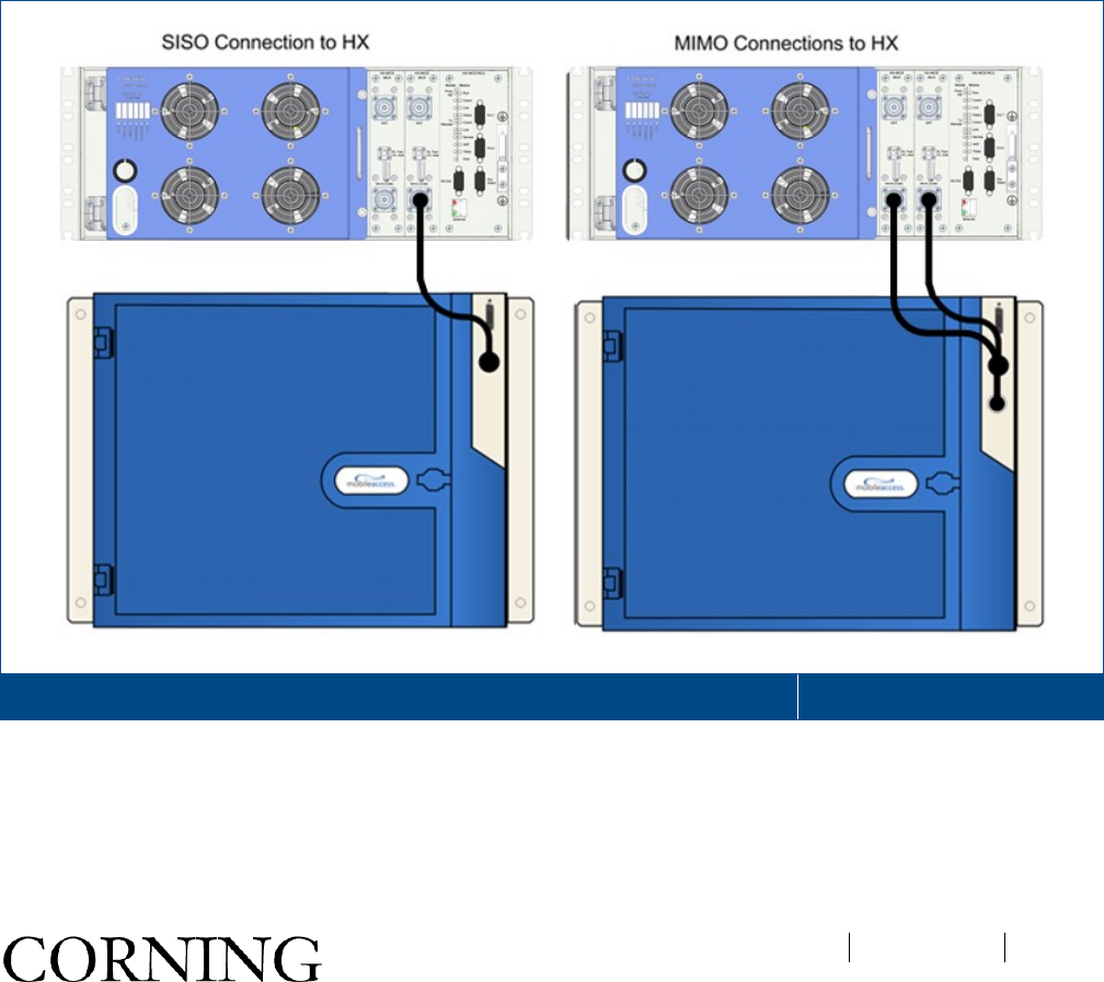
1.17.1.1 Installations with Additional HX Unit
1. Connect the HX WCS MUX “WB RU” 4.3-10 Type duplexed RF port to the HX duplexed antenna port.
Note: For SISO installations the connections are from HX WCS ‘ANT. 1 MUX to HX ‘ANTENNA PORT 1’; For
MIMO installations additional connections are performed between HX WCS ‘ANT. 2 MUX’ to HX ‘ANTENNA
PORT 2.
RF Connections Between HX WCS and Existing HX (Left-SISO; Right – MIMO) Figure 3-20
오류! 지정한 스타일은 사용되지 않습니다.
CMA-TBD-AEN
Page 43
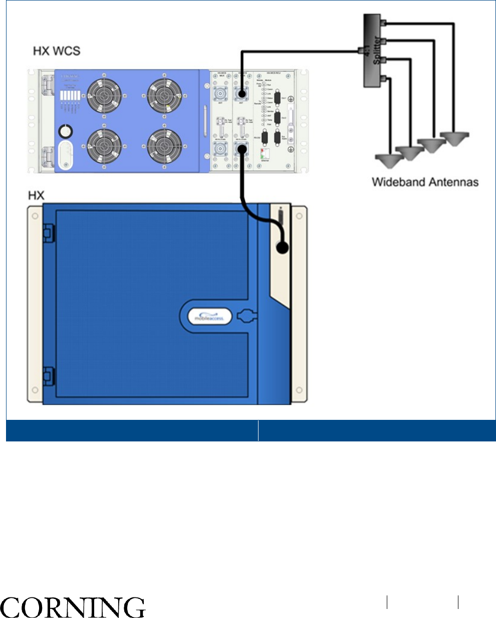
2. Connect broadband antenna coax to ANT port of HX-WCS MUX module (two for MIMO models) and to
broadband DAS antennas.
ATTENTION! Terminate any unused RF ports with a 50 ohm termination load.
Example of HX WCS Antenna Connections (SISO) Figure 3-21
3. Open the cabinet doors for both HX WCS and HX remotes to access optic fiber connection ports.
오류! 지정한 스타일은 사용되지 않습니다.
CMA-TBD-AEN
Page 44
4. Disconnect the fiber connection from the existing HX remote (from the base unit) and re-connect to the
bottom SC APC optic port of the HX-WCS module (Right ANT. 1 module for SISO and Left ANT. 2 module
for MIMO)
• Downlink: Connect the fiber optic cable pigtails from splice box, which comes from the BU port, to the
corresponding HX RU module (MIMO models include two service modules with fiber connections).
• Uplink: Connect the fiber optic cable pigtails from splice box, which comes from the RU service module(s), to
the uplink port that connects to the BU.
Note: Keep in mind the rules for handling and connecting F/O cables. The F/O cables will be connected to
the associated BU in the communication room at a later phase.
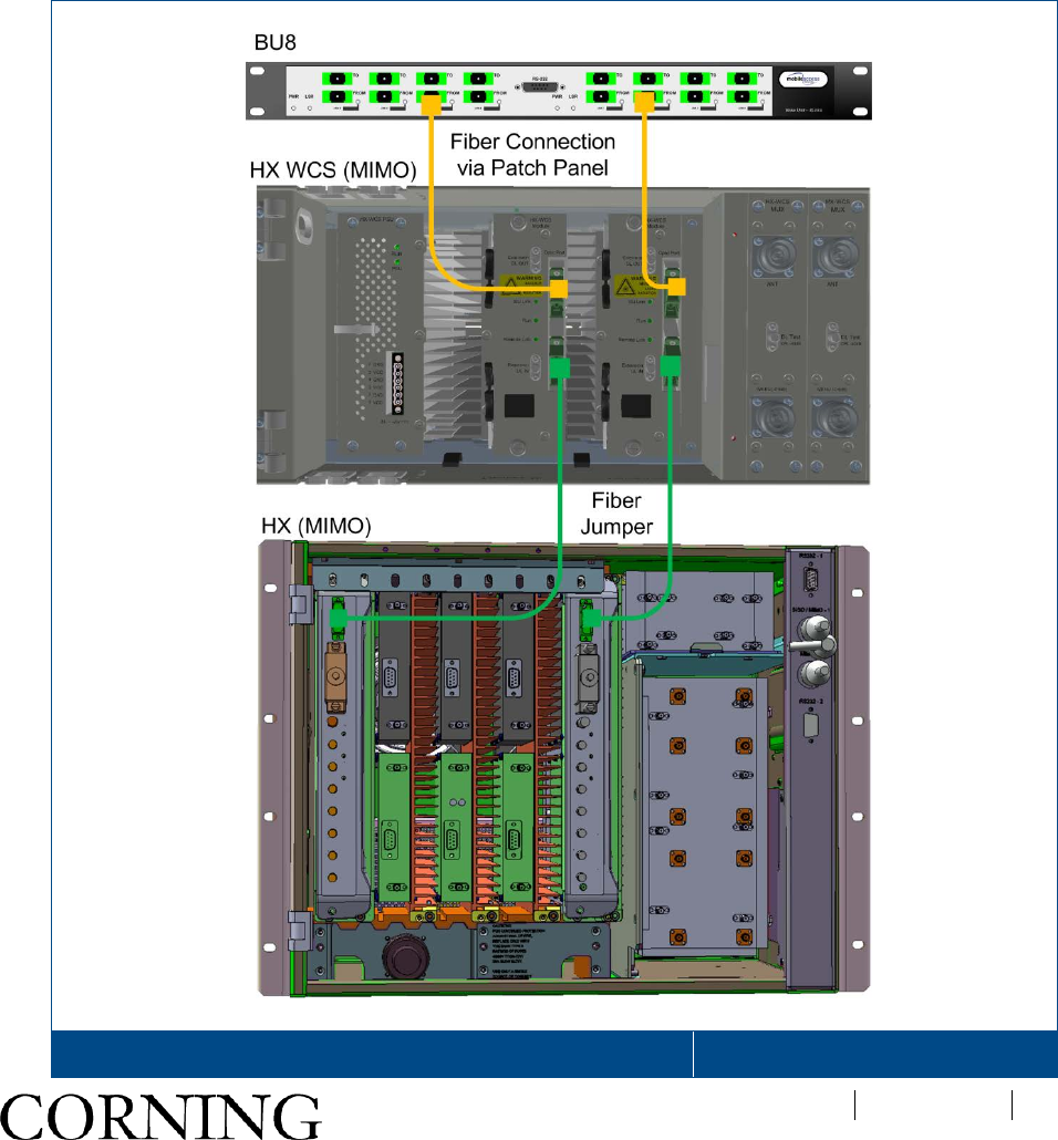
Example of HX WCS (MIMO) Fiber Connections to Existing HX Figure 3-22
오류! 지정한 스타일은 사용되지 않습니다.
CMA-TBD-AEN
Page 45
1.17.1.2 Installations with MA1000/MA2000 Remote
This section provides instructions on how to perform expansion connections between the HX WCS unit and an
MA1000/MA2000 remote unit. The RF connections between the HX WCS unit and an MA1000/MA2000 remote
require an EPM unit which interfaces between the HX WCS and the service combiner unit (SCU) required for the
MA1000/MA2000 remote.
IMPORTANT! Two EPM units are required for MIMO installations – each one connects to an HX WCS ‘ANT.”
Port.
To connect expansion connections
1. Connect the HX WCS MUX “ANT” 4.3-10 Type duplexed RF port to the EPM front panel high band Mini
DIN 4.3-10 input port. See Figure 3-15.
Example of Connection between HX WCS and EPM Figure 3-23
오류! 지정한 스타일은 사용되지 않습니다.
CMA-TBD-AEN
Page 46
2. Connect the four rear panel EPM low-band N-Type input ports to the corresponding SCU N-Type
ANTENNA PORTS”.
Note: The location of the SCU ‘ANTENNA PORTS” differ depending on model:
• SCU-4/SCU-8 units - antenna ports located on rear panel
• SCU-F/SCU-FT - antenna ports located on front panel
Example of Connection between HX WCS and EPM Figure 3-24
3. Connect the four EPM rear panel Mini DIN 4.3-10 ‘ANT’ output ports to the wideband antennas.
오류! 지정한 스타일은 사용되지 않습니다.
CMA-TBD-AEN
Page 47
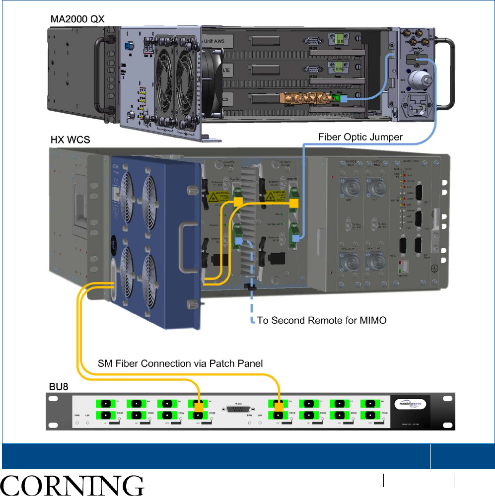
4. Open cabinet door to access HX WCS module(s) with the fiber optic interface, route the DL and UL fibers
through the front door slot and (see Figure 3-17) and connect as follows:
• Optic fiber connections to/from headend (BU):
o Downlink: Connect the fiber optic cable pigtails from splice box, leading from the BU port, to the
corresponding HX WCS module “From HE” SC APC optic port (MIMO models include two service
modules with fiber connections).
o Uplink: Connect the fiber optic cable pigtails from splice box, which comes from the HX WCS service
module(s), “From HE” SC APC uplink port to the BU.
• Using fiber optic jumpers, connect the HX WCS module “To RU” SC APC optic to the SC APC optic port of
the MA1000/MA2000 remote unit.
IMPORTANT! Keep in mind the rules for handling and connecting F/O cables.
Example of HX WCS Fiber optic Connections to BU and MA2000 Remote Indoor Connections
(MIMO)
Figure 3-25
오류! 지정한 스타일은 사용되지 않습니다.
CMA-TBD-AEN
Page 48
Note: EPM and SCU not shown in Figure 3-17 for clarity.
1.17.2 Ground Connection
Required tools and components
The following additional (not supplied) tools and components are required for connecting the system ground:
• Grounding wire - grounding wire should be sized according to local and national installation requirements.
The provided grounding lug supports 14 AWG to 10 AWG stranded copper (or 12 AWG to 10 AWG solid)
wire conductors.
Note: The length of the grounding wire depends on the proximity to proper grounding facilities.
• Phillips-head screwdriver
• Crimping tool to crimp the grounding wire to the grounding lug.
• Wire-stripping tool to remove the insulation from the grounding wire
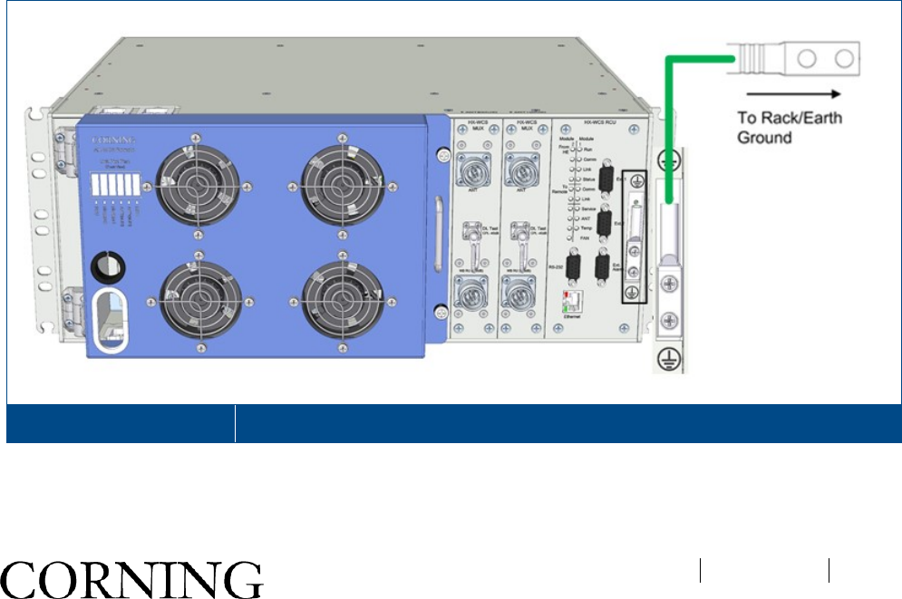
To ground the HX WCS
1. Use a wire-stripping tool to remove approximately 0.4 inch (10.9 mm) of the covering from the end of the
grounding wire.
2. Insert the stripped end of the grounding wire into the open end of the grounding lug.
3. Crimp the grounding wire in the barrel of the grounding lug. Verify that the ground wire is securely
attached to the ground lug by holding the ground lug and gently pulling on the ground wire.
4. Prepare the other end of the grounding wire and connect it to an appropriate grounding point at the site to
ensure adequate earth ground.
HX WCS Grounding Lug Figure 3-26
오류! 지정한 스타일은 사용되지 않습니다.
CMA-TBD-AEN
Page 49
1.17.3 Power Connections
WARNING! Before connecting or disconnecting ground or power wires to the chassis, ensure that power is
disconnected from the DC circuit. To disconnect power, locate the circuit breaker on the panel board that services
the DC circuit, and switch the circuit breaker to the OFF position. Verify zero voltage at the power terminals on the
chassis before proceeding.
DC power specifications
• Power source rating: 34-48 V DC
• Max Consumption: SISO = 90 W; MIMO = 150 W
• Compatible wire size for plug: 30~12 AWG
• No. of required pairs: Minimum of one pair (up to three)
• Max. current consumption for connector: for 20 AWG = 4.5 A; (max. 5A)
To connect DC power:
Note: The internal power connections and other connections should already be connected.
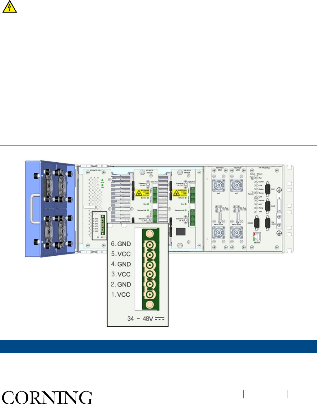
1. Open cabinet door, if not already open, to access Power Supply Unit (PSU).
HX WCS PSU DC Connector Figure 3-27
2. Connect the DC wires leading from the power source to the Dinkle 2ESDFM terminal block plug according
to indicated pin out on the PSU DC terminal block:

오류! 지정한 스타일은 사용되지 않습니다.
CMA-TBD-AEN
Page 50
• Identify the positive and negative terminals on power source feed positions. The wiring sequence is positive
to positive and negative to negative.
• Open the terminal block screw and insert appropriate feed into the terminal block plug
• Torque the terminal block captive screw (above the installed wire lead), using a ratcheting torque screwdriver.
Recommended torque is 0.49N•m.
• Repeat above steps for all feeds
• Insert the plug into HX WCS PSU DC terminal block.
1.18 Verifying Normal Operation
1. Verify that the fans are operational.
2. Verify system normal operation via the system and service LEDs – refer to section 1.4.1 (Table 1-2) and
section 1.4.2 (Table 1-4) for LED descriptions.
Note: The HX WCS monitoring and management capabilities are performed via the host BU unit. Refer to the SC-
450 (v7.2 and higher) User Manual for the configuration and management options.
Appendix A: System Specifications
CMA-318-AEN
Page 51
Appendix A: System Specifications
RF Parameters
Supported Services
Frequency Range
Technologies
Band Uplink Downlink
LTE* 2300 LTE2300 2305 - 2315 MHz 2350 – 2360 MHz
* LTE compiles with 3GPP TS 36.106 V10.6.0 (2012-12) table 9.1 unwanted emission.
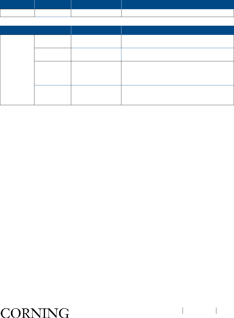
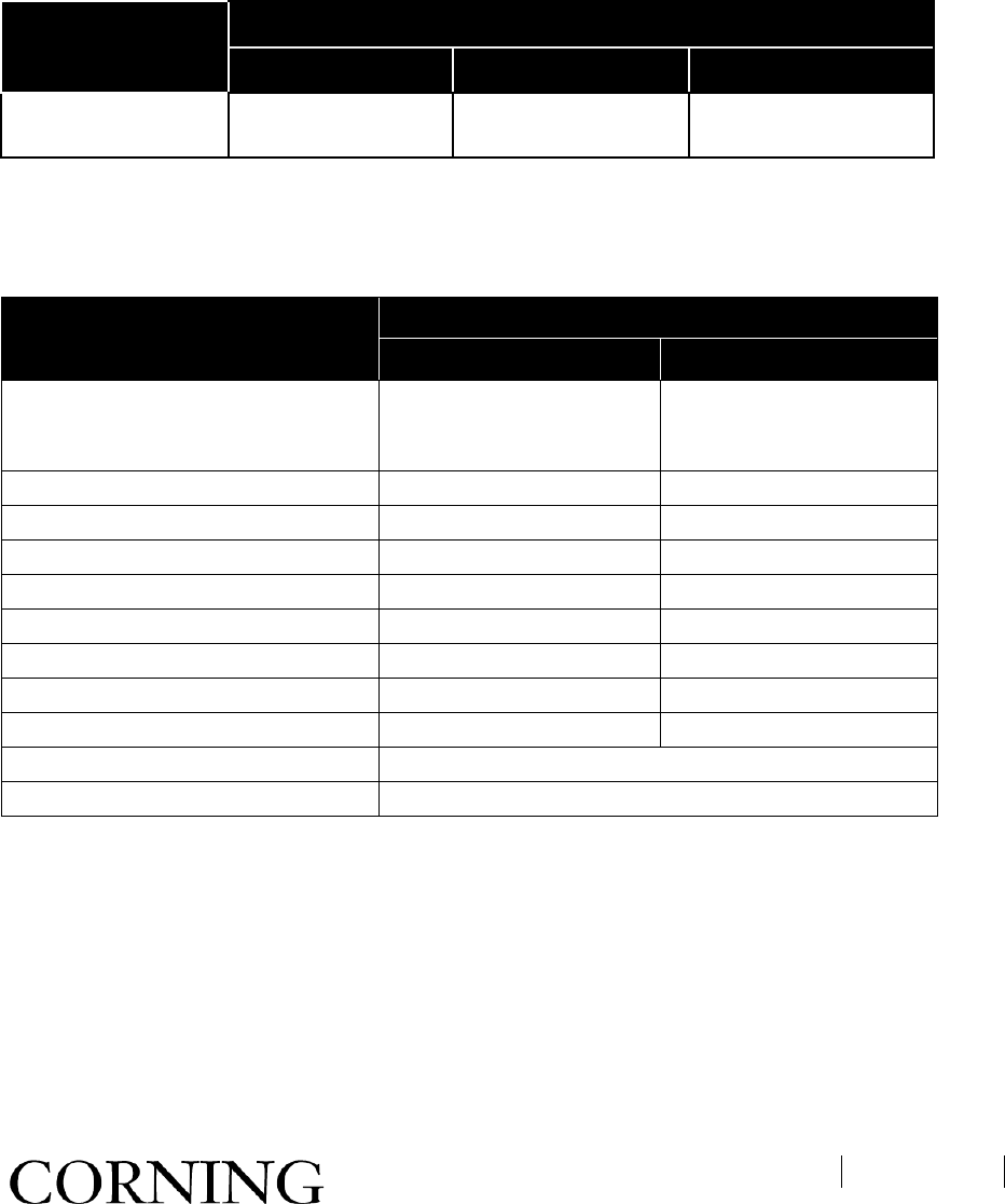
RF Parameters per Service Antenna Port
LTE2300 MHz
RF Parameters DL UL
Max Output Power Per Antenna
Port
1 Operator (Composite)3 (dBm) 33
2 Operators (dBm)
30
4 Operators (dBm) 27
8 Operators (dBm) 24
Mean Gain (dB)
1
33
31
Pin1 (dBm) 0
Input IP3 (dBm) AGC OFF Typical -15
Max. Intermod Distortion (dBm) -13
NF (dB) Typical
6
RF Output Port Impedance 50 ohm
Gain Flatness/Ripple (dB)
2
+/- 1.5
1Factory set mean gain BU without RIU. May be field adjusted using controller system.
2Gain Flatness/Ripple is specified for the non-duplexed port of the system.
Appendix A: System Specifications
CMA-318-AEN
Page 52
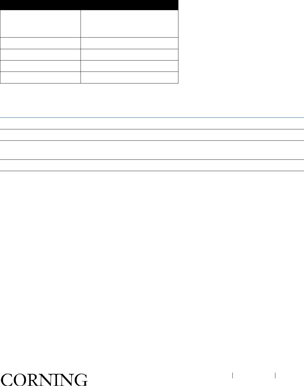
RF Parameters for Diplexer External Input Port
RF Parameters
Frequency Range 698 – 2155 MHz
Insertion Loss 0.6 dB
Isolation 40 dB Min.@ 2305~2315 MHz
Return Loss 16 dB Min.
Power Rating Avg.100 W
Optical Specifications
Max. Optical Budget 3 dB
Optical Connector SC/APC
Fiber Type Single-mode: 9/125µm (Minimum qualifications with ANSI/TIA/EIA-
568-B series, EN50173-1 or ISO/IEC 11801)
Wavelength 1310 ± 10 nm
Maximum Distance Between BU and
Remote Cabinet 2 km

Appendix A: System Specifications
CMA-318-AEN
Page 53
Physical Specifications
Interfaces Chassis:
• One Min DIN 4.3-10 duplexed antenna (‘ANT’) port per multiplexer (one for SISO
units; two for MIMO units)
• One Min DIN 4.3-10 duplexed ‘Expansion’ port per multiplexer (one for SISO
units; two for MIMO units) for interfacing external RF In source
• One SMA-Type female 50Ω port for DL test port per multiplexer (one for SISO
units; two for MIMO units)
• One female RJ-45 local craft port
• One D-Type 9 pin female console port (engineering GUI)
• One six pin pluggable terminal block connector; three VCC and GND pairs
• One two hole grounding lug with 6 gauge wire
• One DB-9 female external alarm connector for external dry contact alarm
connections
Module:
• Four SC APC optical connectors
• Two SMA UL/DL Extension Port connectors
Power • Power Input: 34-48 V DC
• Maximum operating voltage : 28-60 V DC
• Max Power Consumption: 90 W (SISO models); 150 W (MIMO models)
•
Physical Mounting: Wall or 19-in Rack
Dimensions (H
x W x
D):
7.0 x 19 x 15.4 in (176.5 x 492 x 392 mm)
Weight: SISO Services configuration: 48lbs (21.77kg) for SISO-
PLUS / 43lbs (19.5
kg) for SISO-NU
MIMO Services configuration: 55 lbs (24.95 kg)
Cooling Feature Active heat dissipation (Fan)
Environmental Specifications
Operating Temperature -40°C to +65°C (-40°F to 149°F)
Storage Temperature -40°C to +85°C (-40°F to 185°F)
Humidity 10% to 95%, non-condensing
Enclosure IP20

Appendix A: System Specifications
CMA-318-AEN
Page 54
Standards and Approvals
Laser Safety
• CDRH 21 CFR 1040.10, 1040.11 (Except for deviations per notice
No.50)
• IEC/EN 60825-1:1994+A1:2002+A2:2001
Safety
• UL 60950-1
• CAN/CSA-C22.2 No.60950
Radio
• FCC 47: Part 2, 27
RoHS
• RoHS 6 compliant

Appendix B: Ordering Information
CMA-318-AEN
Page 55
Appendix B: Ordering Information
Note: The information listed below is updated up to the document publishing date. Refer to the HX datasheet for
the most updated ordering information.
MobileAccessHX WCS Remote Units
HX WCS Remotes
Service Supported Part Number Description
WCS SISO HX-WCS-SISO-NU MobileAccessHX SISO only remote with support
for WCS band (Non MIMO upgradable in the
field)
WCS SISO HX-WCS-SISO-PLUS MobileAccessHX SISO remote with support for
WCS band (MIMO upgradable in the field)
WCS MIMO HX-WCS-MIMO MobileAccessHX MIMO remote with support for
WCS band
RIU Conditioner Modules
Part Number
Description
RIU--BTSC-WCS RIU-4 conditioner for WCS band
RIU-12-CNDTR-WCS RIU-12 conditioner for WCS band
Upgrade kits
Kit
Part Number
Description
WCS Module HX-WCS-MODULE MobileAccessHX WCS band module for upgrade
from SISO to MIMO
Accessory Kits*
Part Number Description
AK-HX-1K2K-HXN-COMB MobileAccessHX accessory kit combining 1K/2K and HX; External passive
module
AK-HX-ADDON-B2W-MNT
Corning Optical Communications Wireless, Inc. • 13221 Woodland Park rd, Suite 400 • Herndon, VA 20171 USA
866
-436-9266 • FAX: 703-848-0280 • Tech Support Hotline: 410-553-2086 or 800-787-1266 • www.corning.com/opcomm
Corning Optical Communications Wireless
reserves the right to improve, enhance and modify the features and specifications of Corning Optical Communications
products
without prior notification. All other trademarks are the properties of their respective owners. Corning MobileAccess is ISO 9
001 certified. © 2013 Corning Optical
Communications
. All rights reserved. Published in the USA.
UM
_HX WCS_709C017601 A00_29JUNE2015