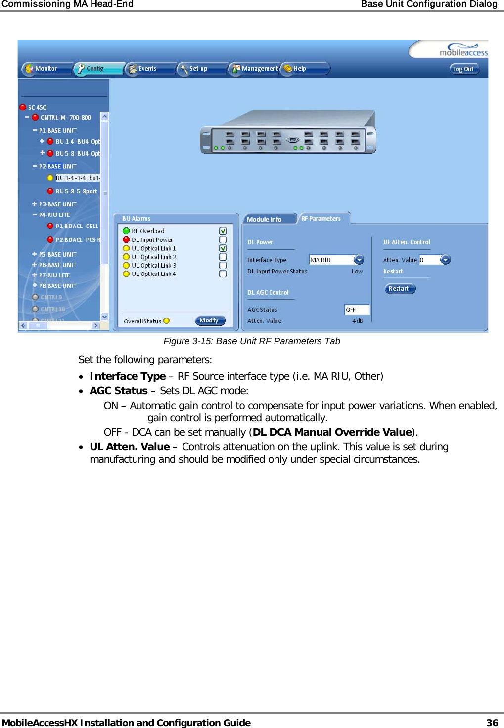
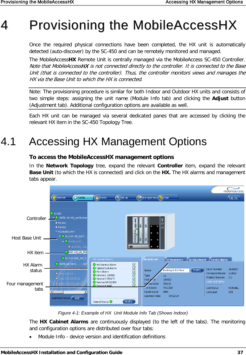
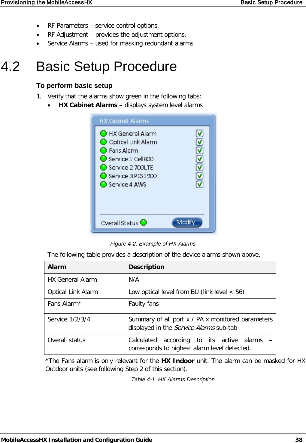
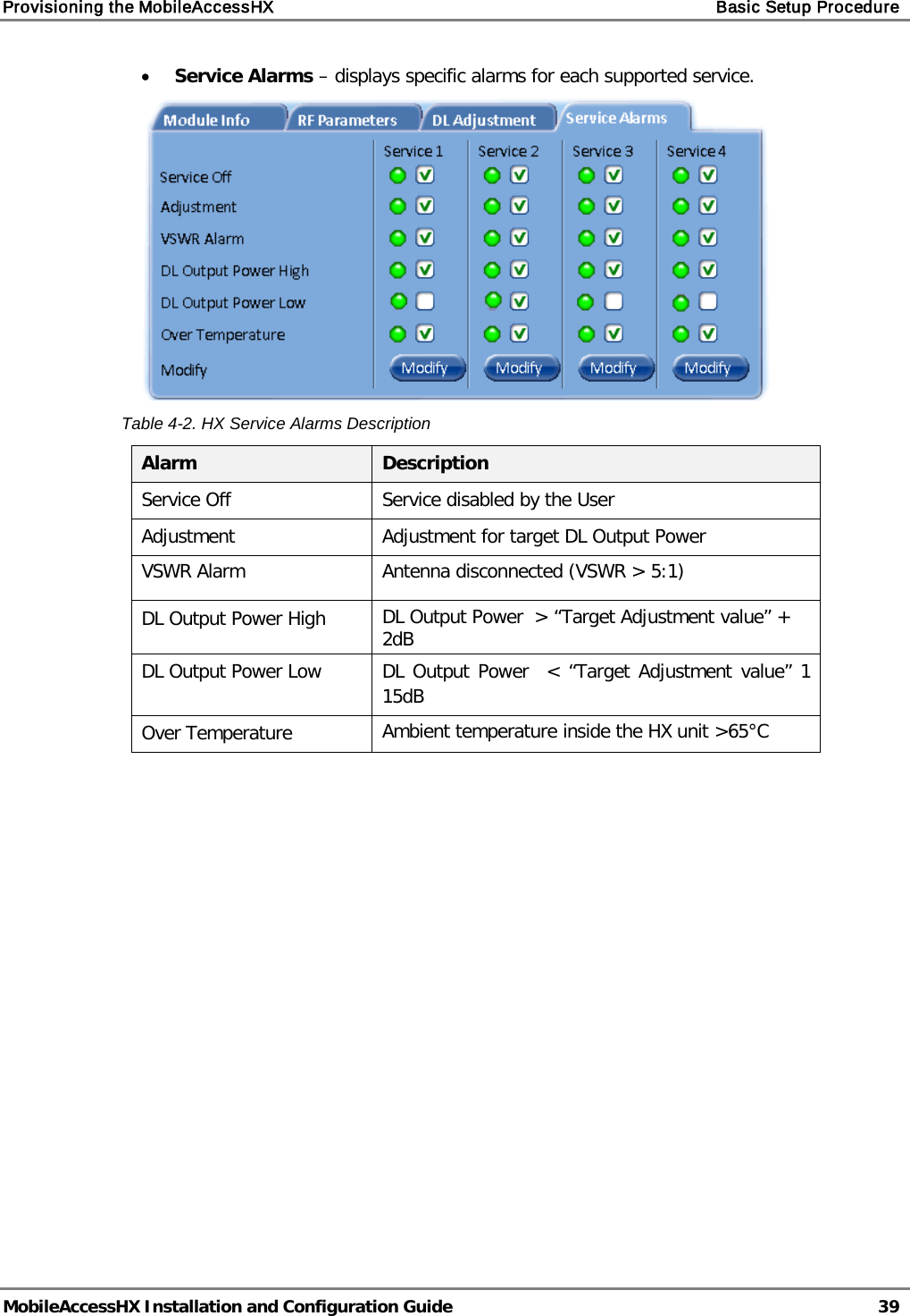
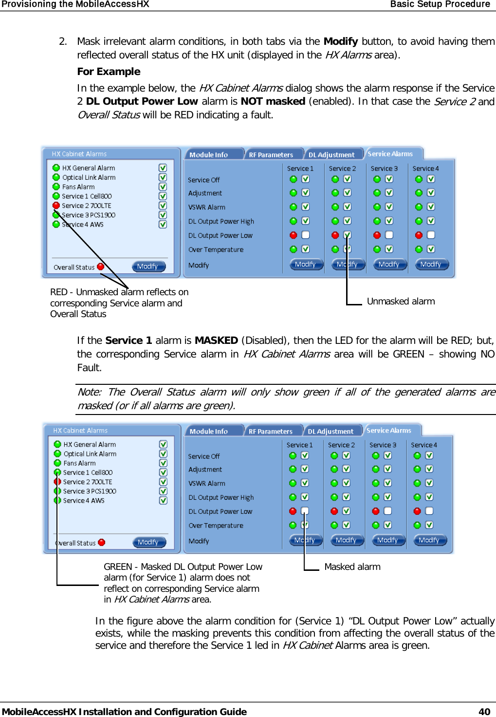
Corning Optical Communication HXCPL70MAM HX HIGH POWER DAS REMOTE UNIT MIMO User Manual MbileAccessHX 2W UM
Corning Optical Communication Wireless HX HIGH POWER DAS REMOTE UNIT MIMO MbileAccessHX 2W UM
Contents
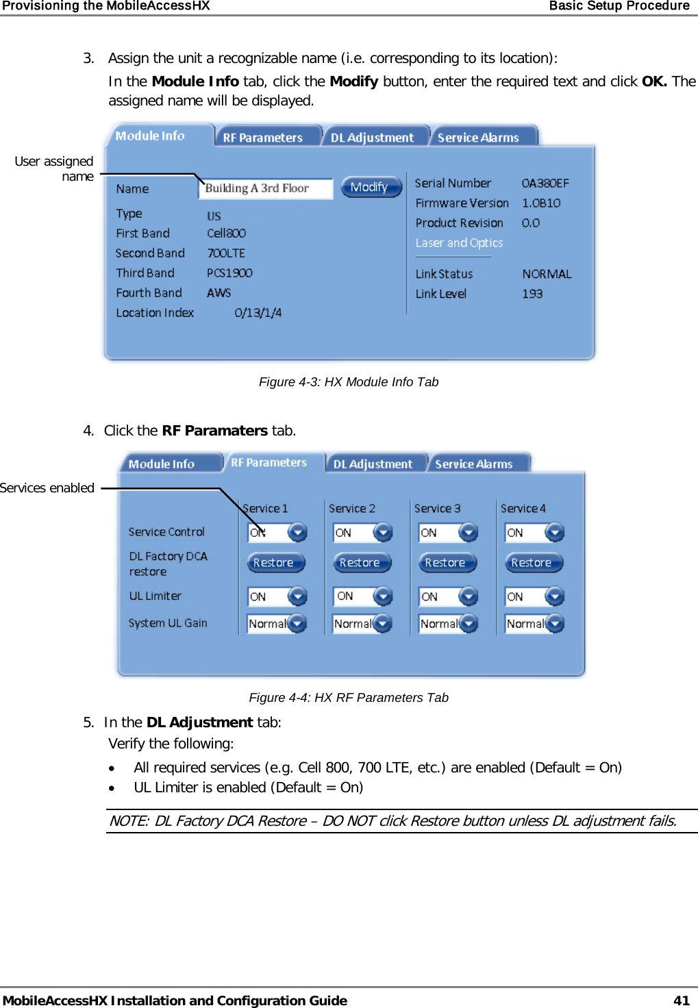
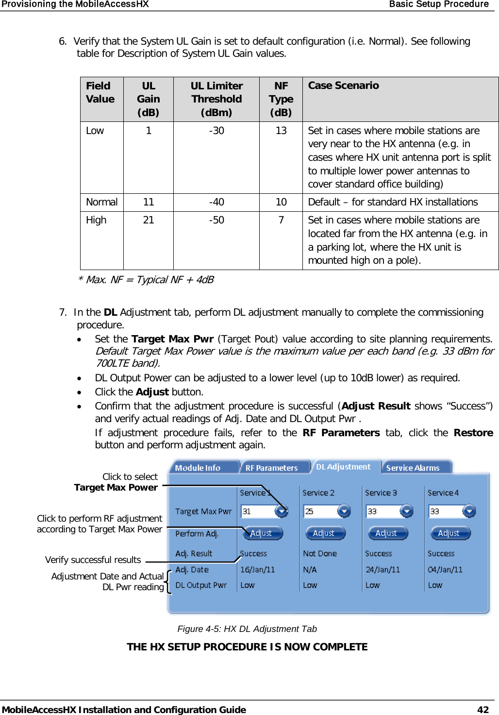
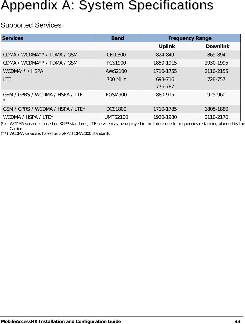
- 1. Users Manual
- 2. User Manual
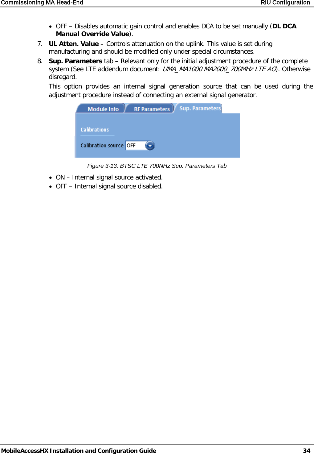
Users Manual
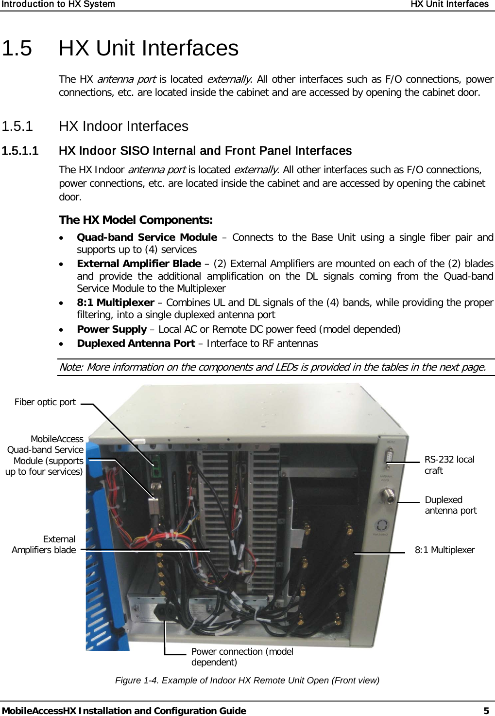
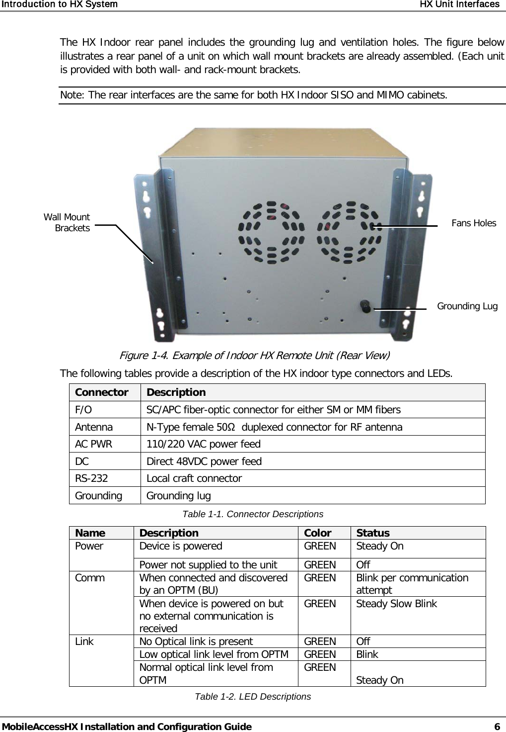
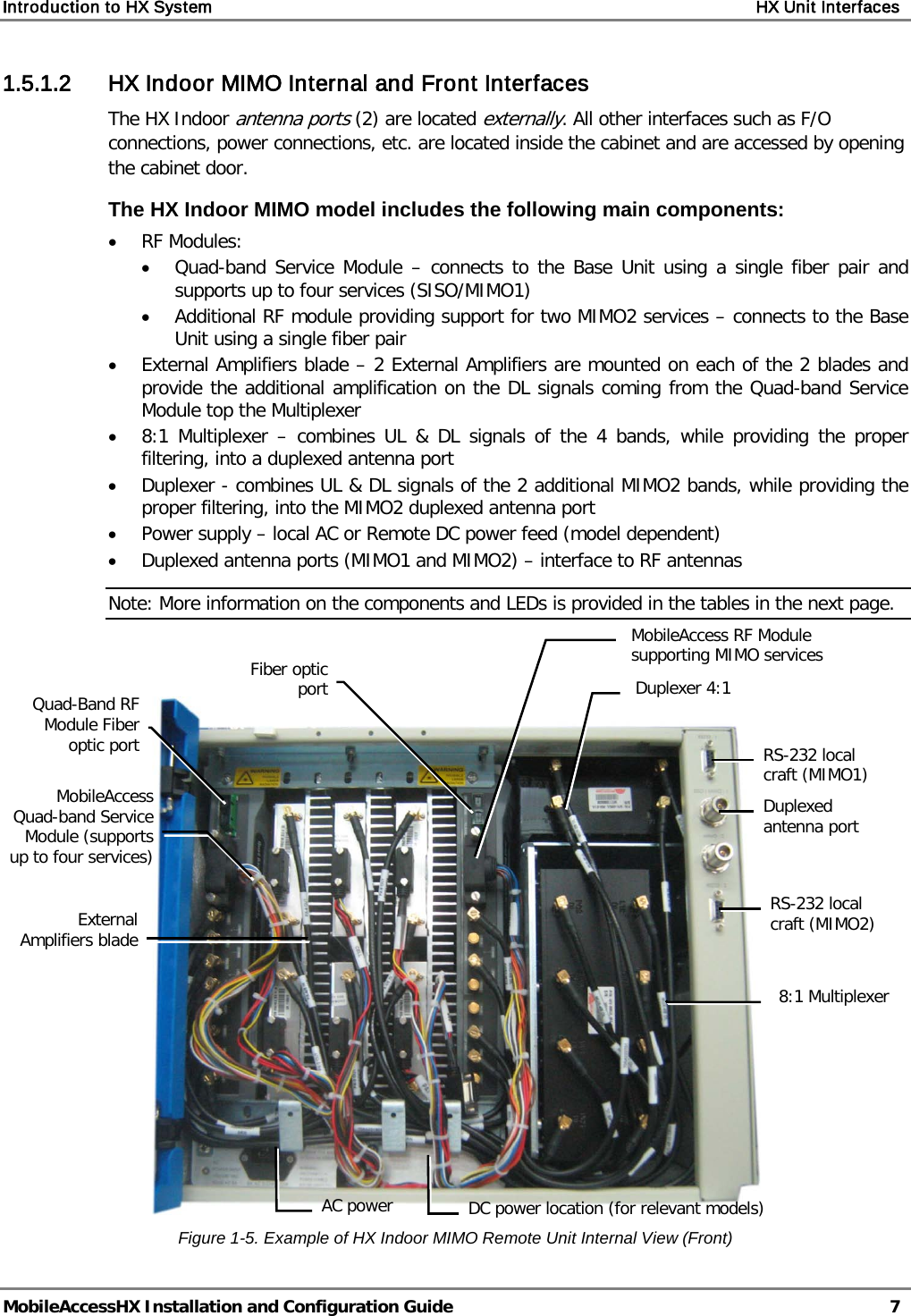
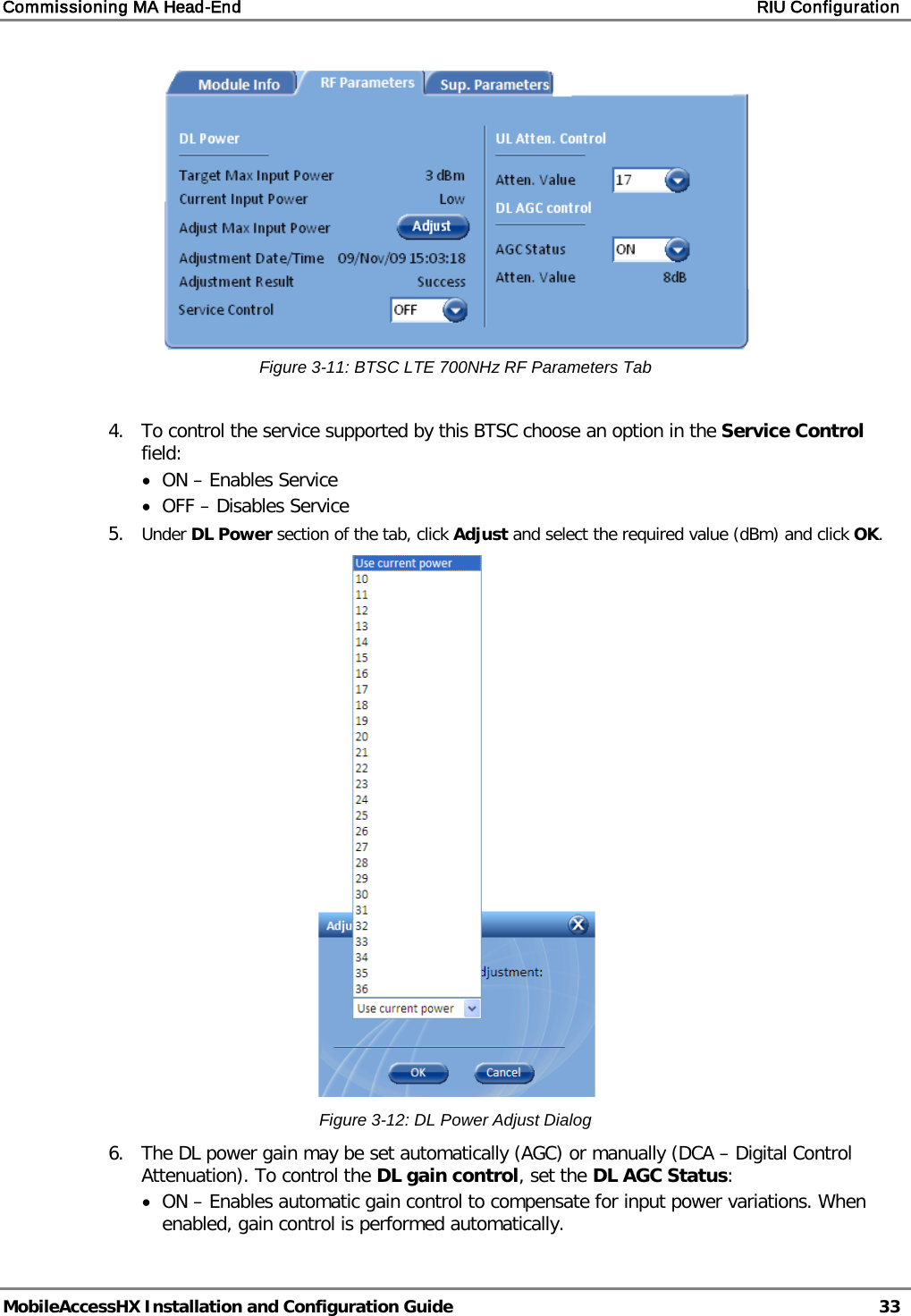
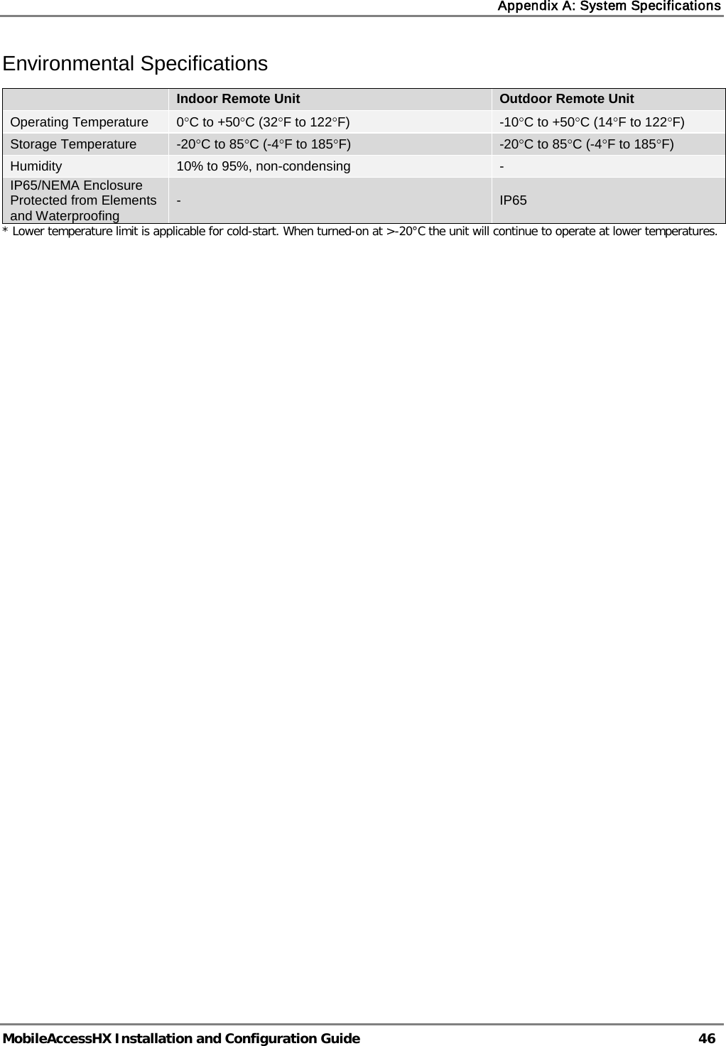
![Appendix A: System Specifications MobileAccessHX Installation and Configuration Guide 45 Optical Specifications Optical Output Power <3.0mW Max. Optical Budget 2 dB for fiber + 1 dB for connectors (assumed) = 3 dB total. 300 m Multi-mode Optical Loss per Mated-pair Connectors 0.5dB (max) Optical Connector SC/APC Fiber Type Single-mode: 9/125um Multi-mode: 50/125 um or 62.5/125um (Minimum qualifications with ANSI/TIA/EIA-568-B series, EN50173-1 or ISO/IEC 11801) Wavelength 1310±10nm Maximum Distance Between Base Unit and Remote Cabinet 2km for SMF 300m for MMF Physical Specifications – MobileAccessHX Remote Unit Indoor Remote Unit Outdoor Remote Unit Ports (1) SC/APC fiber-optic pair connector (1) N-Type female 50Ω connector for antenna (1) Power connector for 110/220VAC power feed or (4) Power connectors for up to (4) direct 48VDC power feeds (1) D-Type 9 pins RS-232 connector for local craft (1) SC/APC fiber-optic pair connector (1) N-Type female 50Ω connector for antenna (1) Power connector for 110/220VAC power feed or (4) Power connectors for up to 4 direct 48VDC power feeds (1) D-Type 9 pins RS-232 connector for local craft Power Local Power (AC) or Remote DC power feed options: 90-264 V AC or 36-75V DC Max Power Consumption: 350W Local Power (AC) or Remote DC Power feed options: 90-264 V AC or 36-75V DC Max Power Consumption: 350W Physical Dimensions Mounting: Wall or Rack Dimensions: 43cm x 38cm x 35cm (16.9” x 14.9” x 13.8”) [X,Y,Z] Weight: (3) Services SISO configuration: 30Kg (66 lb) (4) Services SISO configuration: 32Kg (71 lb) (2) SISO+(2) MIMO Services Configuration: 42Kg (92 lb) Mounting: Wall or Poll Dimensions: 43cm x 63cm x 30cm (16.9” x 24.8” x 11.8”) [X,Y,Z] Weight (4 Services configuration): 52Kg (114 lb) Cooling Feature Active heat dissipation (Fan) Passive heat dissipation (Heat Sink)](https://usermanual.wiki/Corning-Optical-Communication/HXCPL70MAM.Users-Manual/User-Guide-1637795-Page-55.png)