Corning Optical Communication HXP19A17 HX HIGH POWER DAS REMOTE UNIT PCS/AWS User Manual
Corning Optical Communication Wireless HX HIGH POWER DAS REMOTE UNIT PCS/AWS Users Manual
UserManual.wiki
>
Corning Optical Communication
>
HXP19A17 User Manual
Users Manual
Navigation menu
Upload a User Manual
Namespaces
Wiki Guide
HTML
PDF
Info
Views
User Manual
Discussion / Help
Navigation
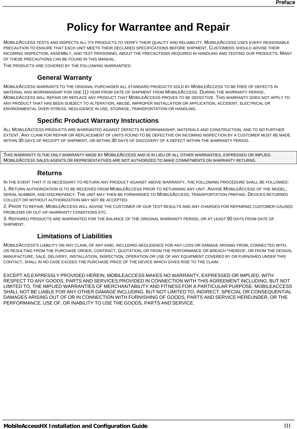
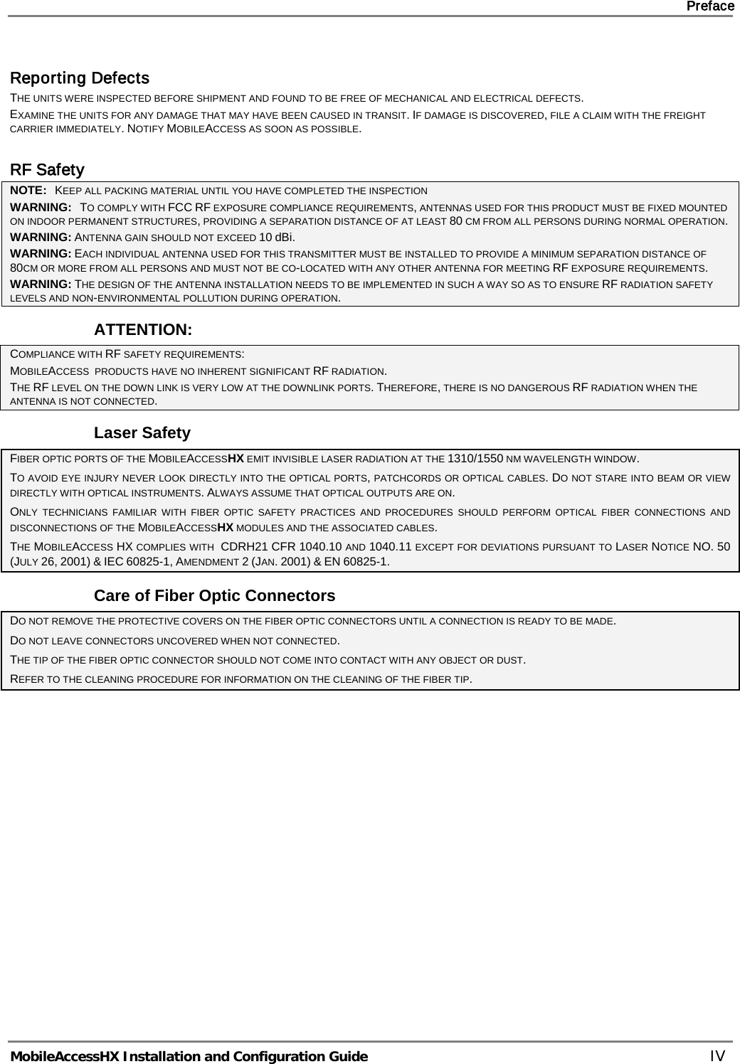
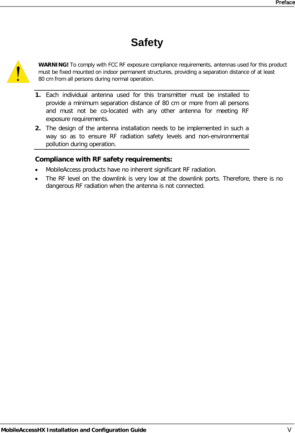
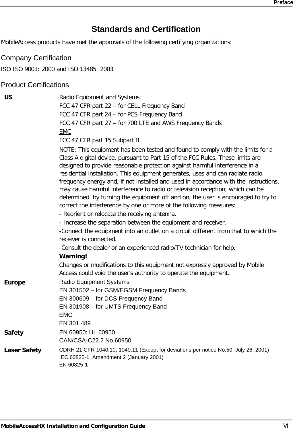
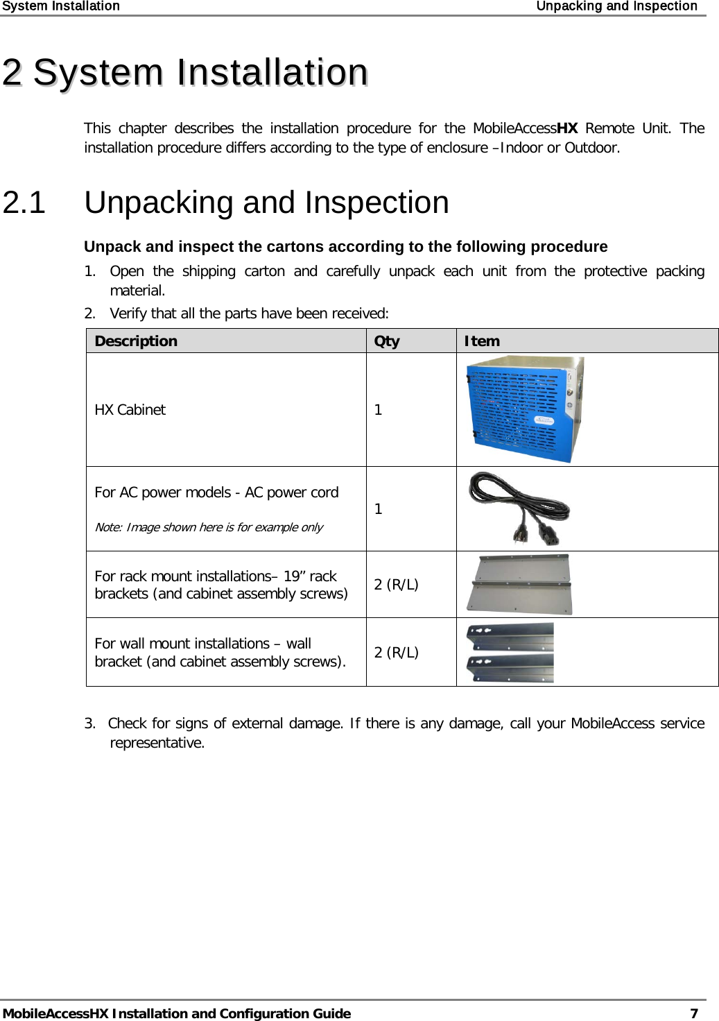
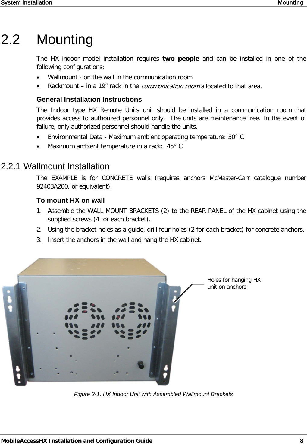
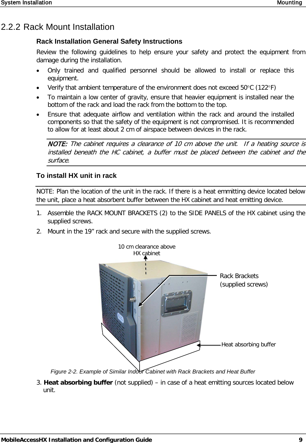
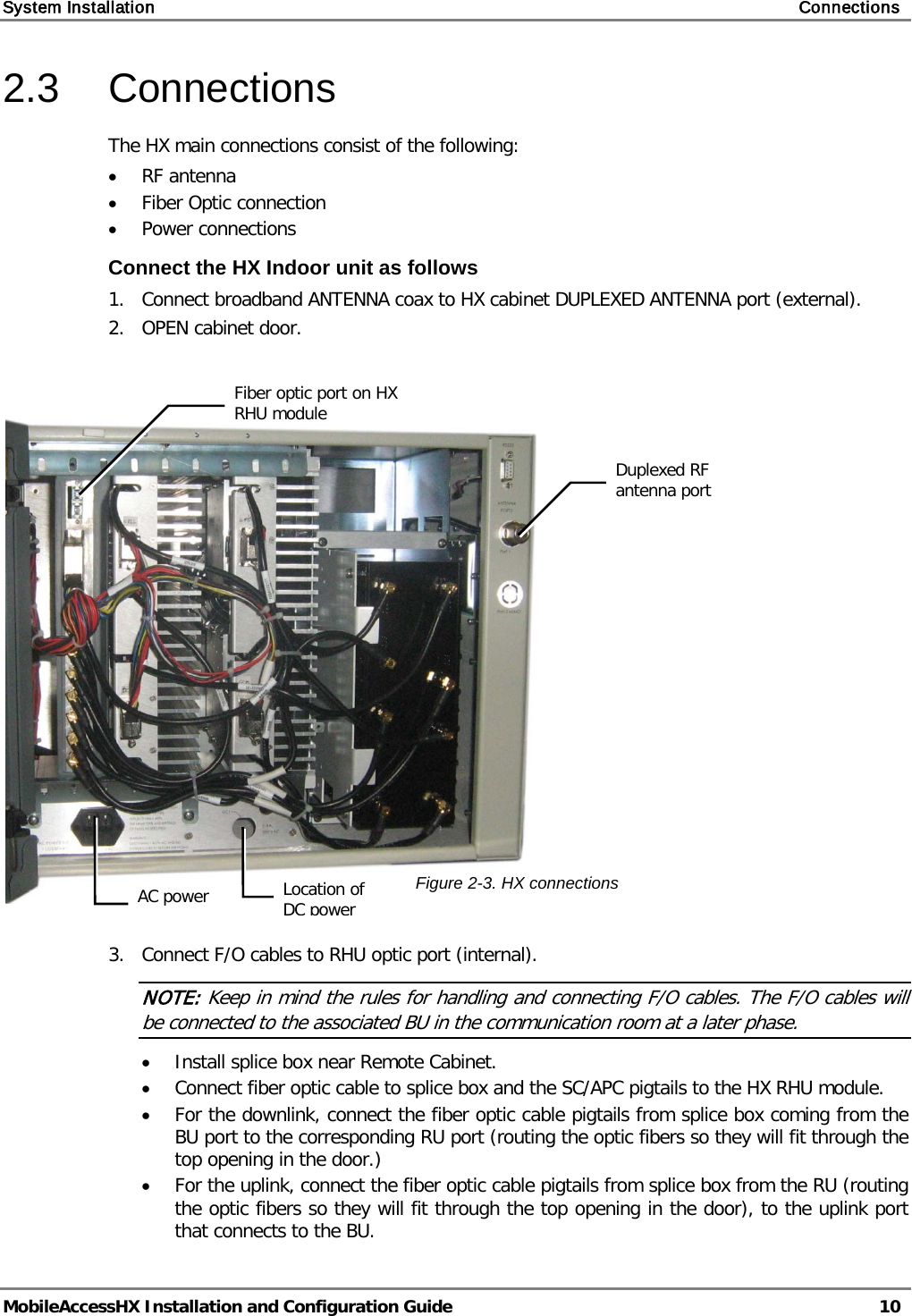
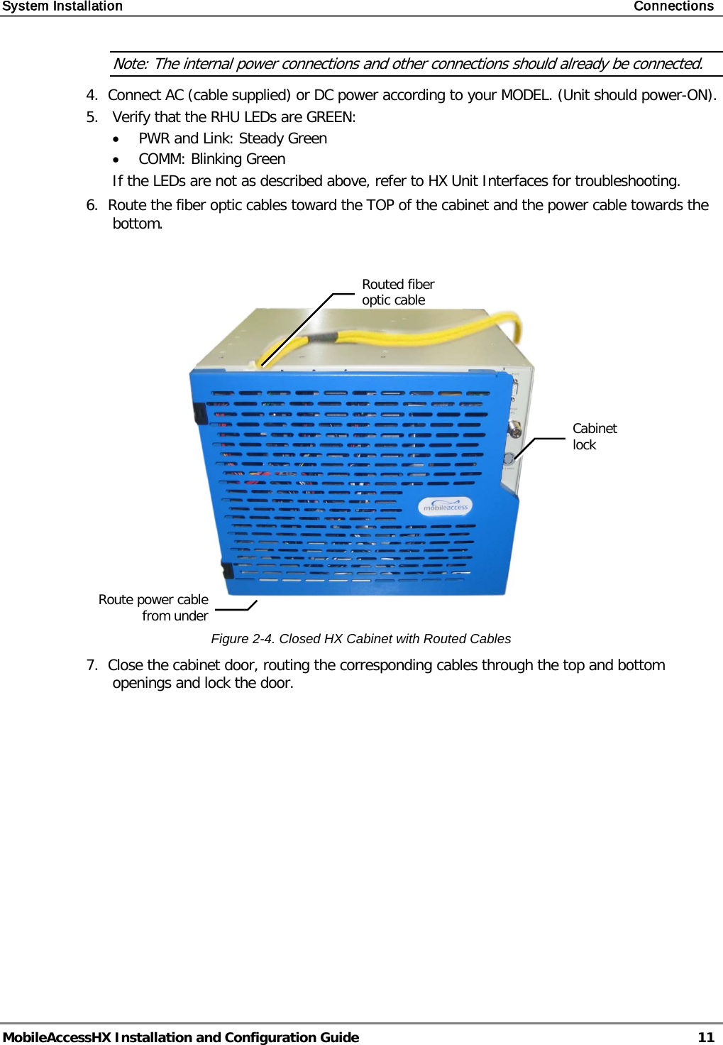
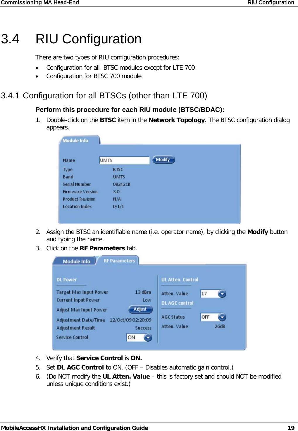
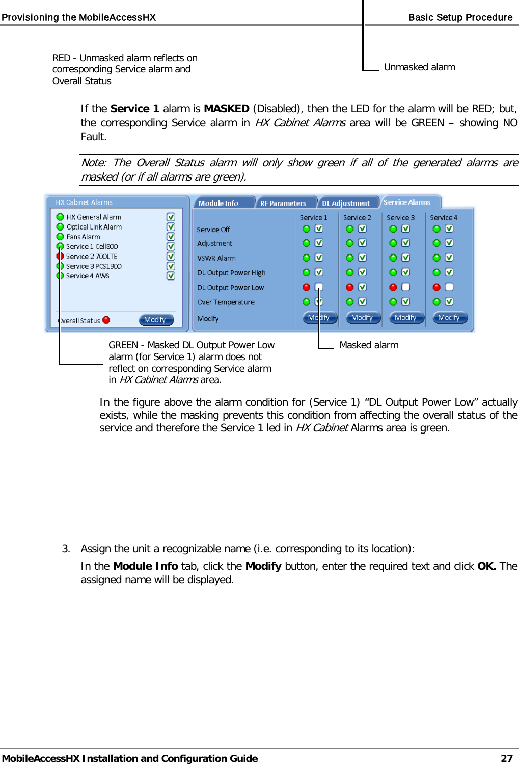
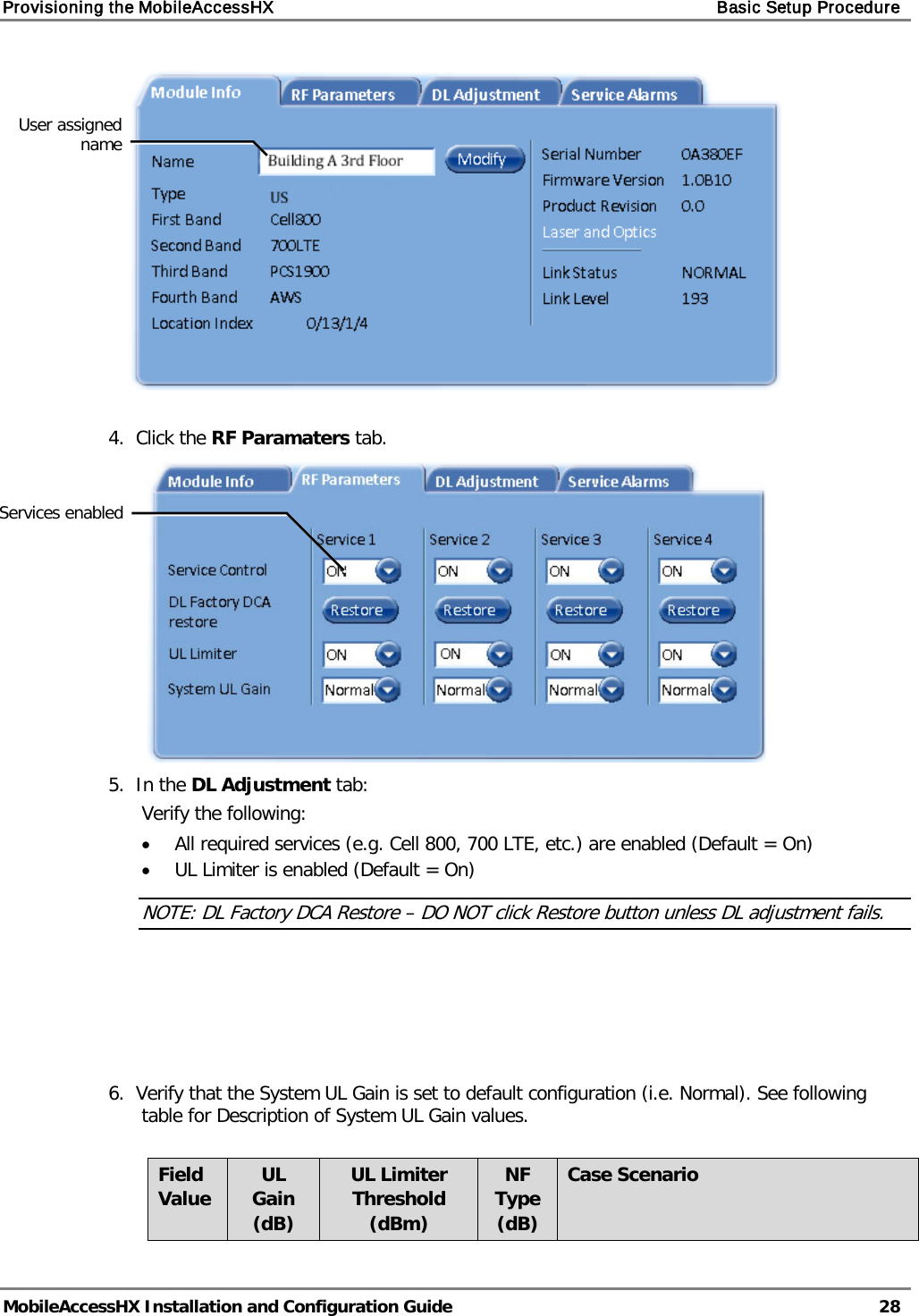
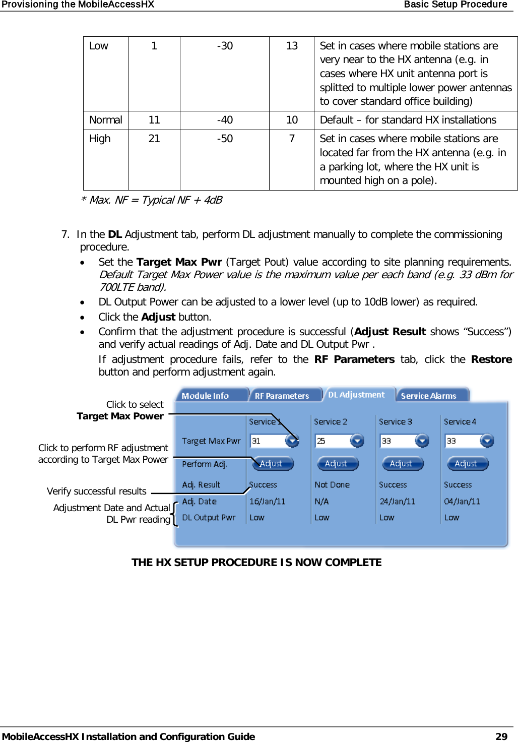
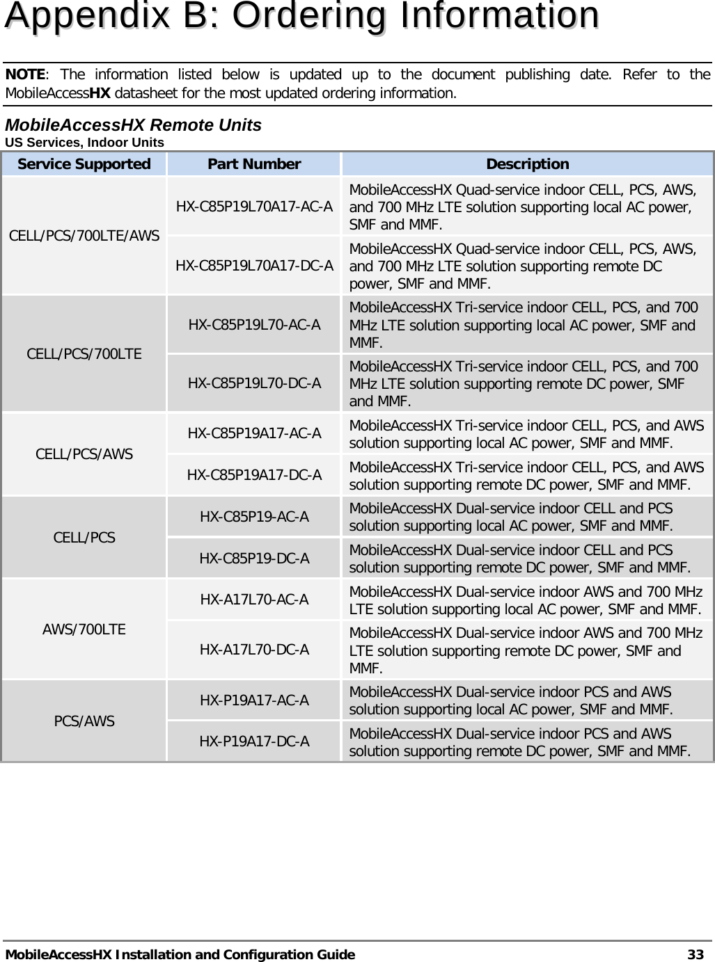
![Appendix A: System Specifications MobileAccessHX Installation and Configuration Guide 32 Optical Specifications Optical Output Power <3.0mW Max. Optical Budget 2 dB for fiber + 1 dB for connectors (assumed) = 3 dB total. 300 m Multi-mode Optical Loss per Mated-pair Connectors 0.5dB (max) Optical Connector SC/APC Fiber Type Single-mode: 9/125um Multi-mode: 50/125 um or 62.5/125um (Minimum qualifications with ANSI/TIA/EIA-568-B series, EN50173-1 or ISO/IEC 11801) Wavelength 1310±10nm Maximum Distance Between Base Unit and Remote Cabinet 2km for SMF 300m for MMF Physical Specifications – MobileAccessHX Remote Unit Indoor Remote Unit Outdoor Remote Unit Ports (1) SC/APC fiber-optic pair connector (1) N-Type female 50Ω connector for antenna (1) Power connector for 110/220VAC power feed or (4) Power connectors for up to (4) direct 48VDC power feeds (1) D-Type 9 pins RS-232 connector for local craft (1) SC/APC fiber-optic pair connector (1) N-Type female 50Ω connector for antenna (1) Power connector for 110/220VAC power feed or (4) Power connectors for up to 4 direct 48VDC power feeds (1) D-Type 9 pins RS-232 connector for local craft Power Local Power (AC) or Remote DC power feed options: 90-264 V AC or 36-75V DC Max Power Consumption: 350W Local Power (AC) or Remote DC Power feed options: 90-264 V AC or 36-75V DC Max Power Consumption: 350W Physical Dimensions Mounting: Wall or Rack Dimensions: 43cm x 38cm x 35cm (16.9” x 14.9” x 13.8”) [X,Y,Z] Weight (4 Services configuration): 32Kg (71 lb) Mounting: Wall or Poll Dimensions: 43cm x 63cm x 30cm (16.9” x 24.8” x 11.8”) [X,Y,Z] Weight (4 Services configuration): 52Kg (114 lb) Environmental Specifications Indoor Remote Unit Outdoor Remote Unit Operating Temperature 0°C to +50°C (32°F to 122°F) -10°C to +50°C (14°F to 122°F) Storage Temperature -20°C to 85°C (-4°F to 185°F) -20°C to 85°C (-4°F to 185°F) Humidity 10% to 95%, non-condensing - Ingress Protection - IP65](https://usermanual.wiki/Corning-Optical-Communication/HXP19A17/User-Guide-1477331-Page-40.png)