Corning Optical Communication HXP19A17 HX HIGH POWER DAS REMOTE UNIT PCS/AWS User Manual
Corning Optical Communication Wireless HX HIGH POWER DAS REMOTE UNIT PCS/AWS Users Manual
Users Manual

MobileAccessHX High Power
DAS System
Installation and Configuration Guide
P/N: 709C006801
REV: A0
Date: 19-MAY-11

Preface
MobileAccessHX Installation and Configuration Guide II
MobileAccess
8391 Old Courthouse Road, Suite 300, Vienna, VA 22182
Tel: +1(866)436-9266, +1(703)848-0200 TAC: +1(800)787-1266, Fax: +1(703)848-0280
http://www.MobileAccess.com
© COPYRIGHT 2011, MOBILEACCESS NETWORKS INC. ALL RIGHTS RESERVED.
MOBILEACCESS IS A REGISTERED TRADEMARK OF MOBILEACCESS. THIS DOCUMENT CONTAINS OTHER TRADEMARKS, TRADE NAMES AND SERVICE
MARKS OF MOBILEACCESS AND OTHER ORGANIZATIONS, ALL OF WHICH ARE THE PROPERTY OF THEIR RESPECTIVE OWNERS.
THIS DOCUMENT CONTAINS CONFIDENTIAL AND PROPRIETARY INFORMATION OF MOBILEACCESS AND MAY NOT BE COPIED, TRANSMITTED, STORED
IN A RETRIEVAL SYSTEM OR REPRODUCED IN ANY FORMAT OR MEDIA, IN WHOLE OR IN PART, WITHOUT THE PRIOR WRITTEN CONSENT OF
MOBILEACCESS. INFORMATION CONTAINED IN THIS DOCUMENT SUPERSEDES ANY PREVIOUS MANUALS, GUIDES, SPECIFICATIONS, DATA SHEETS OR
OTHER INFORMATION THAT MAY HAVE BEEN PROVIDED OR MADE AVAILABLE TO THE USER.
THIS DOCUMENT IS PROVIDED FOR INFORMATIONAL PURPOSES ONLY, AND MOBILEACCESS DOES NOT WARRANT OR GUARANTEE THE ACCURACY,
ADEQUACY, QUALITY, VALIDITY, COMPLETENESS OR SUITABILITY FOR ANY PURPOSE OF THE INFORMATION CONTAINED IN THIS DOCUMENT.
MOBILEACCESS RESERVES THE RIGHT TO MAKE UPDATES, IMPROVEMENTS AND ENHANCEMENTS TO THIS DOCUMENT AND THE PRODUCTS TO
WHICH IT RELATES AT ANY TIME WITHOUT PRIOR NOTICE TO THE USER. MOBILEACCESS MAKES NO WARRANTIES, EXPRESS OR
IMPLIED, INCLUDING, WITHOUT LIMITATION, THOSE OF MERCHANTABILITY AND FITNESS FOR A PARTICULAR PURPOSE,
WITH RESPECT TO THIS DOCUMENT OR ANY INFORMATION CONTAINED HEREIN.

Preface
MobileAccessHX Installation and Configuration Guide III
Policy for Warrantee and Repair
MOBILEACCESS TESTS AND INSPECTS ALL ITS PRODUCTS TO VERIFY THEIR QUALITY AND RELIABILITY. MOBILEACCESS USES EVERY REASONABLE
PRECAUTION TO ENSURE THAT EACH UNIT MEETS THEIR DECLARED SPECIFICATIONS BEFORE SHIPMENT. CUSTOMERS SHOULD ADVISE THEIR
INCOMING INSPECTION, ASSEMBLY, AND TEST PERSONNEL ABOUT THE PRECAUTIONS REQUIRED IN HANDLING AND TESTING OUR PRODUCTS. MANY
OF THESE PRECAUTIONS CAN BE FOUND IN THIS MANUAL.
THE PRODUCTS ARE COVERED BY THE FOLLOWING WARRANTIES:
General Warranty
MOBILEACCESS WARRANTS TO THE ORIGINAL PURCHASER ALL STANDARD PRODUCTS SOLD BY MOBILEACCESS TO BE FREE OF DEFECTS IN
MATERIAL AND WORKMANSHIP FOR ONE (1) YEAR FROM DATE OF SHIPMENT FROM MOBILEACCESS. DURING THE WARRANTY PERIOD,
MOBILEACCESS WILL REPAIR OR REPLACE ANY PRODUCT THAT MOBILEACCESS PROVES TO BE DEFECTIVE. THIS WARRANTY DOES NOT APPLY TO
ANY PRODUCT THAT HAS BEEN SUBJECT TO ALTERATION, ABUSE, IMPROPER INSTALLATION OR APPLICATION, ACCIDENT, ELECTRICAL OR
ENVIRONMENTAL OVER-STRESS, NEGLIGENCE IN USE, STORAGE, TRANSPORTATION OR HANDLING.
Specific Product Warranty Instructions
ALL MOBILEACCESS PRODUCTS ARE WARRANTED AGAINST DEFECTS IN WORKMANSHIP, MATERIALS AND CONSTRUCTION, AND TO NO FURTHER
EXTENT. ANY CLAIM FOR REPAIR OR REPLACEMENT OF UNITS FOUND TO BE DEFECTIVE ON INCOMING INSPECTION BY A CUSTOMER MUST BE MADE
WITHIN 30 DAYS OF RECEIPT OF SHIPMENT, OR WITHIN 30 DAYS OF DISCOVERY OF A DEFECT WITHIN THE WARRANTY PERIOD.
THIS WARRANTY IS THE ONLY WARRANTY MADE BY MOBILEACCESS AND IS IN LIEU OF ALL OTHER WARRANTIES, EXPRESSED OR IMPLIED.
MOBILEACCESS SALES AGENTS OR REPRESENTATIVES ARE NOT AUTHORIZED TO MAKE COMMITMENTS ON WARRANTY RETURNS.
Returns
IN THE EVENT THAT IT IS NECESSARY TO RETURN ANY PRODUCT AGAINST ABOVE WARRANTY, THE FOLLOWING PROCEDURE SHALL BE FOLLOWED:
1. RETURN AUTHORIZATION IS TO BE RECEIVED FROM MOBILEACCESS PRIOR TO RETURNING ANY UNIT. ADVISE MOBILEACCESS OF THE MODEL,
SERIAL NUMBER, AND DISCREPANCY. THE UNIT MAY THEN BE FORWARDED TO MOBILEACCESS, TRANSPORTATION PREPAID. DEVICES RETURNED
COLLECT OR WITHOUT AUTHORIZATION MAY NOT BE ACCEPTED.
2. PRIOR TO REPAIR, MOBILEACCESS WILL ADVISE THE CUSTOMER OF OUR TEST RESULTS AND ANY CHARGES FOR REPAIRING CUSTOMER-CAUSED
PROBLEMS OR OUT-OF-WARRANTY CONDITIONS ETC.
3. REPAIRED PRODUCTS ARE WARRANTED FOR THE BALANCE OF THE ORIGINAL WARRANTY PERIOD, OR AT LEAST 90 DAYS FROM DATE OF
SHIPMENT.
Limitations of Liabilities
MOBILEACCESS'S LIABILITY ON ANY CLAIM, OF ANY KIND, INCLUDING NEGLIGENCE FOR ANY LOSS OR DAMAGE ARISING FROM, CONNECTED WITH,
OR RESULTING FROM THE PURCHASE ORDER, CONTRACT, QUOTATION, OR FROM THE PERFORMANCE OR BREACH THEREOF, OR FROM THE DESIGN,
MANUFACTURE, SALE, DELIVERY, INSTALLATION, INSPECTION, OPERATION OR USE OF ANY EQUIPMENT COVERED BY OR FURNISHED UNDER THIS
CONTACT, SHALL IN NO CASE EXCEED THE PURCHASE PRICE OF THE DEVICE WHICH GIVES RISE TO THE CLAIM.
EXCEPT AS EXPRESSLY PROVIDED HEREIN, MOBILEACCESS MAKES NO WARRANTY, EXPRESSED OR IMPLIED, WITH
RESPECT TO ANY GOODS, PARTS AND SERVICES PROVIDED IN CONNECTION WITH THIS AGREEMENT INCLUDING, BUT NOT
LIMITED TO, THE IMPLIED WARRANTIES OF MERCHANTABILITY AND FITNESS FOR A PARTICULAR PURPOSE. MOBILEACCESS
SHALL NOT BE LIABLE FOR ANY OTHER DAMAGE INCLUDING, BUT NOT LIMITED TO, INDIRECT, SPECIAL OR CONSEQUENTIAL
DAMAGES ARISING OUT OF OR IN CONNECTION WITH FURNISHING OF GOODS, PARTS AND SERVICE HEREUNDER, OR THE
PERFORMANCE, USE OF, OR INABILITY TO USE THE GOODS, PARTS AND SERVICE.

Preface
MobileAccessHX Installation and Configuration Guide IV
Reporting Defects
THE UNITS WERE INSPECTED BEFORE SHIPMENT AND FOUND TO BE FREE OF MECHANICAL AND ELECTRICAL DEFECTS.
EXAMINE THE UNITS FOR ANY DAMAGE THAT MAY HAVE BEEN CAUSED IN TRANSIT. IF DAMAGE IS DISCOVERED, FILE A CLAIM WITH THE FREIGHT
CARRIER IMMEDIATELY. NOTIFY MOBILEACCESS AS SOON AS POSSIBLE.
RF Safety
NOTE: KEEP ALL PACKING MATERIAL UNTIL YOU HAVE COMPLETED THE INSPECTION
WARNING: TO COMPLY WITH FCC RF EXPOSURE COMPLIANCE REQUIREMENTS, ANTENNAS USED FOR THIS PRODUCT MUST BE FIXED MOUNTED
ON INDOOR PERMANENT STRUCTURES, PROVIDING A SEPARATION DISTANCE OF AT LEAST 80 CM FROM ALL PERSONS DURING NORMAL OPERATION.
WARNING: ANTENNA GAIN SHOULD NOT EXCEED 10 dBi.
WARNING: EACH INDIVIDUAL ANTENNA USED FOR THIS TRANSMITTER MUST BE INSTALLED TO PROVIDE A MINIMUM SEPARATION DISTANCE OF
80CM OR MORE FROM ALL PERSONS AND MUST NOT BE CO-LOCATED WITH ANY OTHER ANTENNA FOR MEETING RF EXPOSURE REQUIREMENTS.
WARNING: THE DESIGN OF THE ANTENNA INSTALLATION NEEDS TO BE IMPLEMENTED IN SUCH A WAY SO AS TO ENSURE RF RADIATION SAFETY
LEVELS AND NON-ENVIRONMENTAL POLLUTION DURING OPERATION.
ATTENTION:
COMPLIANCE WITH RF SAFETY REQUIREMENTS:
MOBILEACCESS PRODUCTS HAVE NO INHERENT SIGNIFICANT RF RADIATION.
THE RF LEVEL ON THE DOWN LINK IS VERY LOW AT THE DOWNLINK PORTS. THEREFORE, THERE IS NO DANGEROUS RF RADIATION WHEN THE
ANTENNA IS NOT CONNECTED.
Laser Safety
FIBER OPTIC PORTS OF THE MOBILEACCESSHX EMIT INVISIBLE LASER RADIATION AT THE 1310/1550 NM WAVELENGTH WINDOW.
TO AVOID EYE INJURY NEVER LOOK DIRECTLY INTO THE OPTICAL PORTS, PATCHCORDS OR OPTICAL CABLES. DO NOT STARE INTO BEAM OR VIEW
DIRECTLY WITH OPTICAL INSTRUMENTS. ALWAYS ASSUME THAT OPTICAL OUTPUTS ARE ON.
ONLY TECHNICIANS FAMILIAR WITH FIBER OPTIC SAFETY PRACTICES AND PROCEDURES SHOULD PERFORM OPTICAL FIBER CONNECTIONS AND
DISCONNECTIONS OF THE MOBILEACCESSHX MODULES AND THE ASSOCIATED CABLES.
THE MOBILEACCESS HX COMPLIES WITH CDRH21 CFR 1040.10 AND 1040.11 EXCEPT FOR DEVIATIONS PURSUANT TO LASER NOTICE NO. 50
(JULY 26, 2001) & IEC 60825-1, AMENDMENT 2 (JAN. 2001) & EN 60825-1.
Care of Fiber Optic Connectors
DO NOT REMOVE THE PROTECTIVE COVERS ON THE FIBER OPTIC CONNECTORS UNTIL A CONNECTION IS READY TO BE MADE.
DO NOT LEAVE CONNECTORS UNCOVERED WHEN NOT CONNECTED.
THE TIP OF THE FIBER OPTIC CONNECTOR SHOULD NOT COME INTO CONTACT WITH ANY OBJECT OR DUST.
REFER TO THE CLEANING PROCEDURE FOR INFORMATION ON THE CLEANING OF THE FIBER TIP.

Preface
MobileAccessHX Installation and Configuration Guide V
Safety
WARNING! To comply with FCC RF exposure compliance requirements, antennas used for this product
must be fixed mounted on indoor permanent structures, providing a separation distance of at least
80 cm from all persons during normal operation.
1. Each individual antenna used for this transmitter must be installed to
provide a minimum separation distance of 80 cm or more from all persons
and must not be co-located with any other antenna for meeting RF
exposure requirements.
2. The design of the antenna installation needs to be implemented in such a
way so as to ensure RF radiation safety levels and non-environmental
pollution during operation.
Compliance with RF safety requirements:
• MobileAccess products have no inherent significant RF radiation.
• The RF level on the downlink is very low at the downlink ports. Therefore, there is no
dangerous RF radiation when the antenna is not connected.

Preface
MobileAccessHX Installation and Configuration Guide VI
Standards and Certification
MobileAccess products have met the approvals of the following certifying organizations:
Company Certification
ISO ISO 9001: 2000 and ISO 13485: 2003
Product Certifications
US Radio Equipment and Systems
FCC 47 CFR part 22 – for CELL Frequency Band
FCC 47 CFR part 24 – for PCS Frequency Band
FCC 47 CFR part 27 – for 700 LTE and AWS Frequency Bands
EMC
FCC 47 CFR part 15 Subpart B
NOTE: This equipment has been tested and found to comply with the limits for a
Class A digital device, pursuant to Part 15 of the FCC Rules. These limits are
designed to provide reasonable protection against harmful interference in a
residential installation. This equipment generates, uses and can radiate radio
frequency energy and, if not installed and used in accordance with the instructions,
may cause harmful interference to radio or television reception, which can be
determined by turning the equipment off and on, the user is encouraged to try to
correct the interference by one or more of the following measures:
- Reorient or relocate the receiving antenna.
- Increase the separation between the equipment and receiver.
-Connect the equipment into an outlet on a circuit different from that to which the
receiver is connected.
-Consult the dealer or an experienced radio/TV technician for help.
Warning!
Changes or modifications to this equipment not expressly approved by Mobile
Access could void the user’s authority to operate the equipment.
Europe Radio Equipment Systems
EN 301502 – for GSM/EGSM Frequency Bands
EN 300609 – for DCS Frequency Band
EN 301908 – for UMTS Frequency Band
EMC
EN 301 489
Safety EN 60950; UL 60950
CAN/CSA-C22.2 No.60950
Laser Safety CDRH 21 CFR 1040.10, 1040.11 (Except for deviations per notice No.50, July 26, 2001)
IEC 60825-1, Amendment 2 (January 2001)
EN 60825-1
Preface
MobileAccessHX Installation and Configuration Guide VII
About this Guide and Other Relevant Documentation
This user guide describes how to perform the physical installation of the MobileAccessHX
system. The installation procedures of other units (e.g. RIU, SC-450) relevant to the system are
detailed in their user manuals (see
Additional Relevant Documentation
below).
Additional Relevant Documents
The following documents are required if the corresponding units are included in your system.
Document Name
RIU Installation and Configuration Guide
SC-450 Installation and Configuration Guide
MA Software Version Update Tool
List of Acronyms
BDA Bi-Directional Amplifier
BTS Base Transceiver Station
BTSC Base Transceiver Station Conditioner
BU Base Unit
DL Downlink
HX High Power Transmission
RIU Radio Interface Unit
UL Uplink

MobileAccessHX Installation and Configuration Guide VIII
Table of Contents
1 Introduction to HX System .................................................................................................. 1
1.1 System Architecture .................................................................................................................. 3
1.2 Application Topologies ............................................................................................................... 4
1.3 System Monitoring and Management .......................................................................................... 4
1.4 HX Unit Interfaces ..................................................................................................................... 4
2 System Installation .............................................................................................................. 7
2.1 Unpacking and Inspection .......................................................................................................... 7
2.2 Mounting .................................................................................................................................. 8
2.2.1 Wallmount Installation ..................................................................................................... 8
2.2.2 Rack Mount Installation .................................................................................................... 9
Rack Brackets (supplied screws) .............................................................................................. 9
2.3 Connections............................................................................................................................ 10
3 Commissioning MA Head-End .......................................................................................... 12
3.1 Initial Controller Setup ............................................................................................................. 12
3.1.1 Open a Session to the Controller ..................................................................................... 12
3.1.2 IP Address Configuration ................................................................................................ 14
3.2 Configure Controller Settings .................................................................................................... 16
3.3 Device Configuration and Preparation ....................................................................................... 16
3.4 RIU Configuration ................................................................................................................... 19
3.4.1 Configuration for all BTSCs (other than LTE 700) .............................................................. 19
3.4.2 BTSC LTE 700 MHz ........................................................................................................ 20
3.5 Base Unit Configuration Dialog ................................................................................................. 22
4 Provisioning the MobileAccessHX ................................................................................... 24
4.1 Accessing HX Management Options .......................................................................................... 24
4.2 Basic Setup Procedure ............................................................................................................. 25
Appendix A: System Specifications ........................................................................................ 30
RF Parameters ............................................................................................................................... 30
Appendix B: Ordering Information .......................................................................................... 33
Appendix C: Site Preparation .................................................................................................. 37
MobileAccessHX Installation and Configuration Guide 1
1
1
I
In
nt
tr
ro
od
du
uc
ct
ti
io
on
n
t
to
o
H
HX
X
S
Sy
ys
st
te
em
m
The MobileAccessHX is a high power, Distributed Antenna System (DAS) solution for indoors or
outdoors (future option). It is a fiber-fed, compact, scalable multi-service platform designed to
provide complete RF open space coverage for large scale public venues, such as campuses,
stadiums, convention centers, hotels, airports, and train stations.
HX supports multiple wireless technologies and operator services over a single broadband
infrastructure. Using low loss fiber optic cabling remote units can cover distances of up to 2Km
from the BTS signal sources at the head-end.
Front-end wireless RF services are routed, over optic fibers, to HX series remote units that are
securely located at each remote location. These modular service aggregation platforms precisely
combine multiple wireless service signals for simultaneous distribution over a common
broadband infrastructure.
The solution can be deployed in new sites or alongside existing MobileAccess1000 (MA1000)
and/or MobileAccess2000 (MA2000) systems, sharing a common head-end and element
management system (EMS).
Alongside MA1000/MA2000 deployments, MobileAccessHX provides a comprehensive indoor and
outdoor coverage solution for varying site requirements, supporting everything from high-rise
buildings and campus topologies to stadiums and airports.
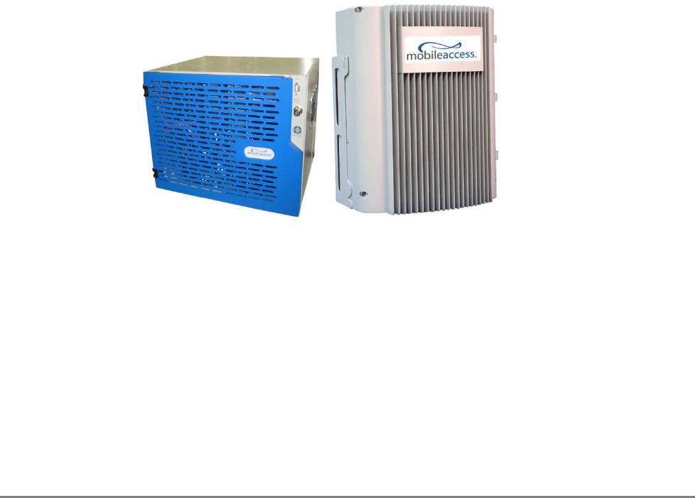
Figure 1-1. HX Indoor Model and HX Outdoor Model (FUTURE)
HX Remote Unit
– Outdoor Model
(FUTURE)
HX Remote Unit –
Indoor Model

Introduction to HX System System Architecture
MobileAccessHX Installation and Configuration Guide 2
Features and Capabilities
• Multi-Service Platform: Accommodates virtually any mix of wireless voice and data
services, eliminating the need for separate overlay networks. Supported services and
technologies include: GSM, UMTS, HSPA, LTE, EDGE, EV-DO, AWS, and more.
• Cost-Effective High Power: Optimizes and reduces the number of antennas required to
cover open areas by offering up to 33dBm (2W) composite power per frequency band.
• Available in both Indoor and outdoor models – outdoor models are weather resistant
in order to precisely meet various location requirements at the site
• Pay-As-You-Grow Design: Can initially be deployed in dual-band, where tri-band or
quad-band configurations can be enabled as needed.
• Carrier-Grade Operation: Advanced signal handling and management ensures carrier-
grade performance in multi-operator deployments.
• Design and Deployment Flexibility:
• Remote unit supports both SM and MM fiber connections.
• Supports two to four wireless frequencies.
• Either remote DC power fed or local AC power fed units available
• Compatible with Existing MA1000/MA2000 Deployment: Shares a common head-
end and EMS in a single deployment.
Introduction to HX System System Architecture
MobileAccessHX Installation and Configuration Guide 3
1.1 System Architecture
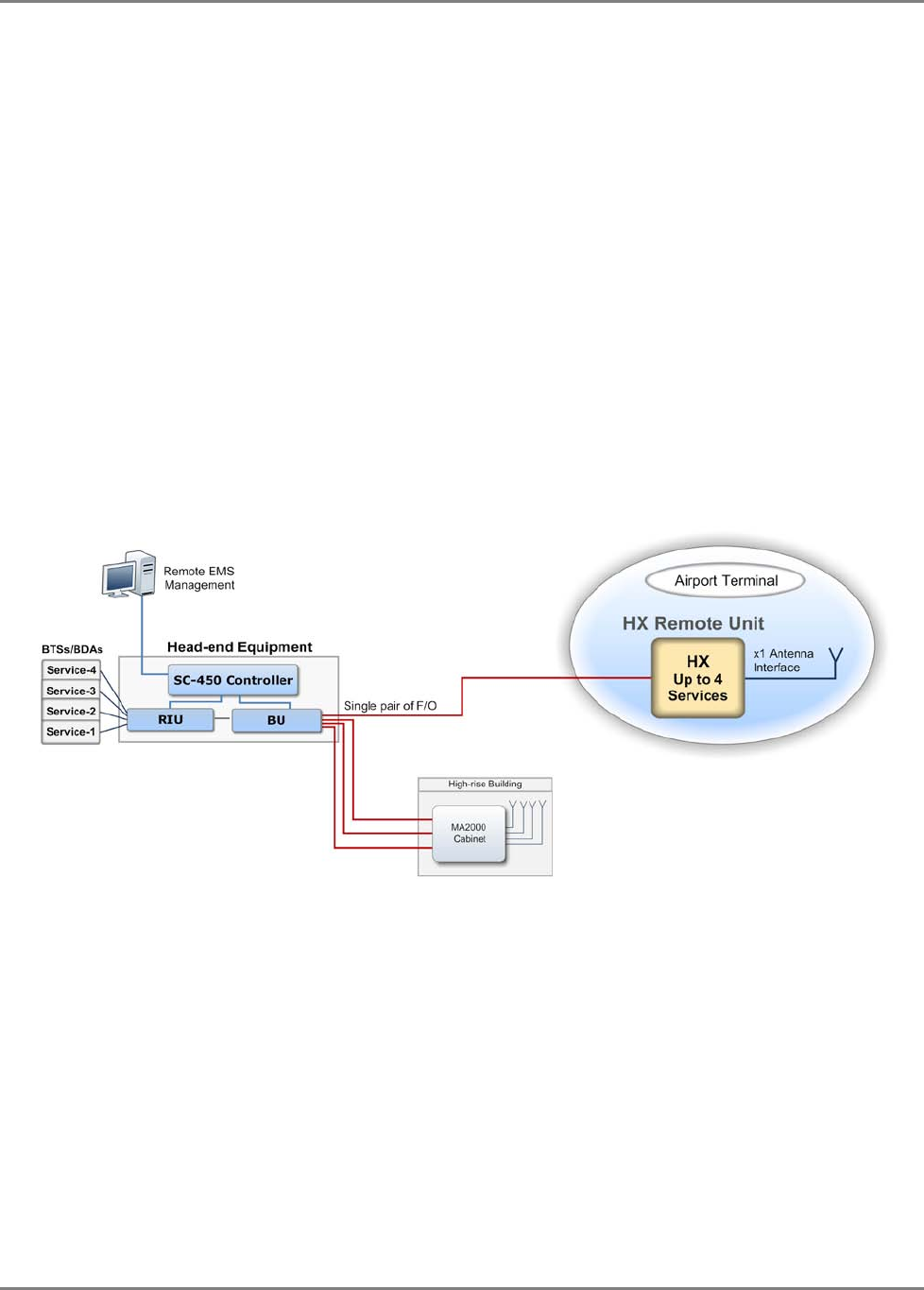
MobileAccessHX provides a complete solution consisting of HX remote units at the remote
locations and head-end elements that are shared with any existing MA1000/MA2000 system that
is either installed or being installed at the site.
In the downlink, at the head-end, the BTS or BDA signal is conditioned by the RIU, ensuring a
constant RF level. The conditioned signal is then converted by the Base Unit to an optical signal
for transport over single or multi-mode fiber to the HX remote units, which are located at the
remote locations. In the uplink, the process is reversed.
The MobileAccessHX Remote Unit consists of a compact enclosure that houses the RF module
(supporting up to four services), power elements, and the required interfaces. At the remote
end, the optical signal is reconverted to RF, amplified, filtered and distributed over the
broadband antenna infrastructure through a single antenna port.
The HX unit is remotely managed from the SC-450 Controller installed at the head-end. The SC-
450 connection to the HX is indirect – via the (host) Base Unit to which the HX is connected. SC-
450 provides a central point for management of MobileAccessHX, MA2000 and MA1000 systems.
Figure 1-2. System Architecture
MobileAccess
HX
architecture
including existing MA2000 / MA1000,
with a common head-end.
Introduction to HX System Application Topologies
MobileAccessHX Installation and Configuration Guide 4
1.2 Application Topologies
MobileAccessHX can be installed in various site topologies, where the setup procedure varies
accordingly:
• High power coverage via a single antenna – installation is usually on pole or mast – used for
open area, stadium, parking lots, etc.
• RF signal is distributed over several antennas via splitters
• Special coverage requirements using directional antennas
1.3 System Monitoring and Management
The MobileAccessHX Remote Unit is centrally managed via the MobileAccess SC-450 Controller.
Note that MobileAccessHX is not connected directly to the controller. It is connected to the Base
Unit (that is connected to the controller). Thus, the controller monitors views and manages the
HX via the Base Unit to which the HX is connected.
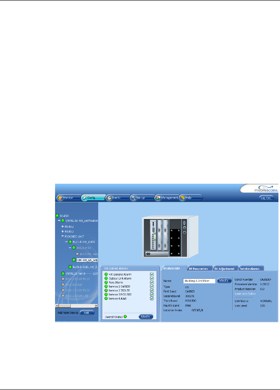
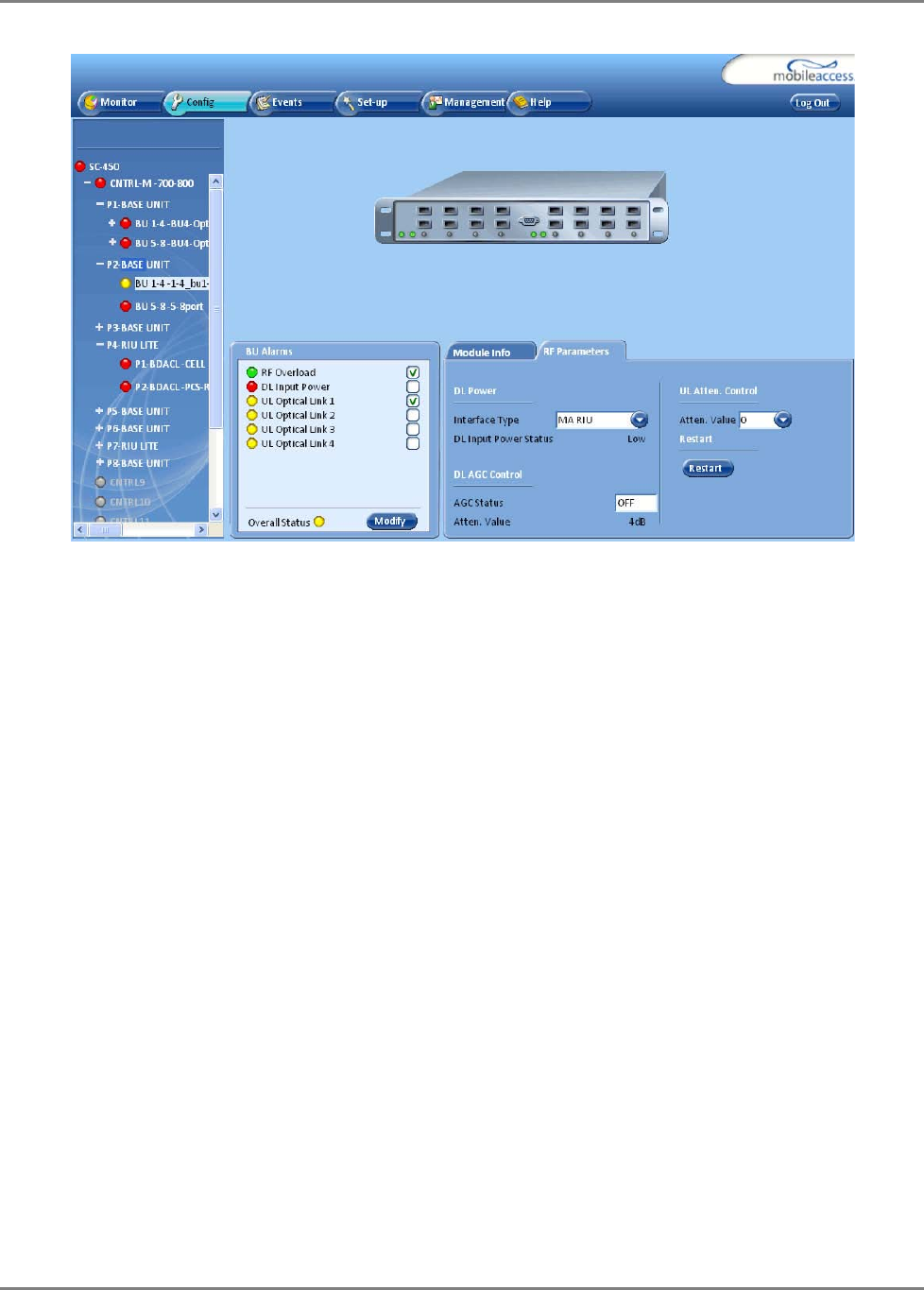
The following shows the Config(uration) tab of the selected HX unit. The system configuration
and management is described in Chapter 4.
1.4 HX Unit Interfaces
The HX
antenna port
is located
externally
. All other interfaces such as F/O connections, power
connections, etc. are located inside the cabinet and are accessed by opening the cabinet door.
Introduction to HX System HX Unit Interfaces
MobileAccessHX Installation and Configuration Guide 5
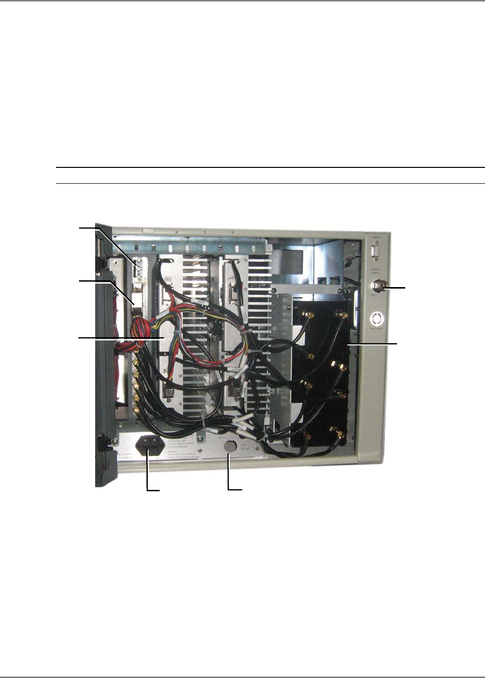
The HX model consists of the following main components – open door view:
• Quad-band Service Module – connects to the Base Unit using a single fiber pair and supports
up to four services
• External Amplifiers blade – 2 External Amplifiers are mounted on each of the 2 blades and
provide the additional amplification on the DL signals coming from the Quad-band Service
Module top the Multiplexer
• 8:1 Multiplexer – combines UL & DL signals of the 4 bands, while providing the proper
filtering, into a single duplexed antenna port
• Power supply – local AC or Remote DC power feed (model depended)
• Duplexed antenna port – interface to RF antennas
Note: More information on the components and LEDs is provided in the tables in the next page.
Figure 1-3. Example of Indoor HX Remote Unit Open front View
MobileAccess
Quad-
band Service
Module
(supports
up to four services)
AC power
8:1 Multiplexer
Duplexed
antenna port
DC power
Fiber optic port
External
Amplifiers blade
Introduction to HX System HX Unit Interfaces
MobileAccessHX Installation and Configuration Guide 6
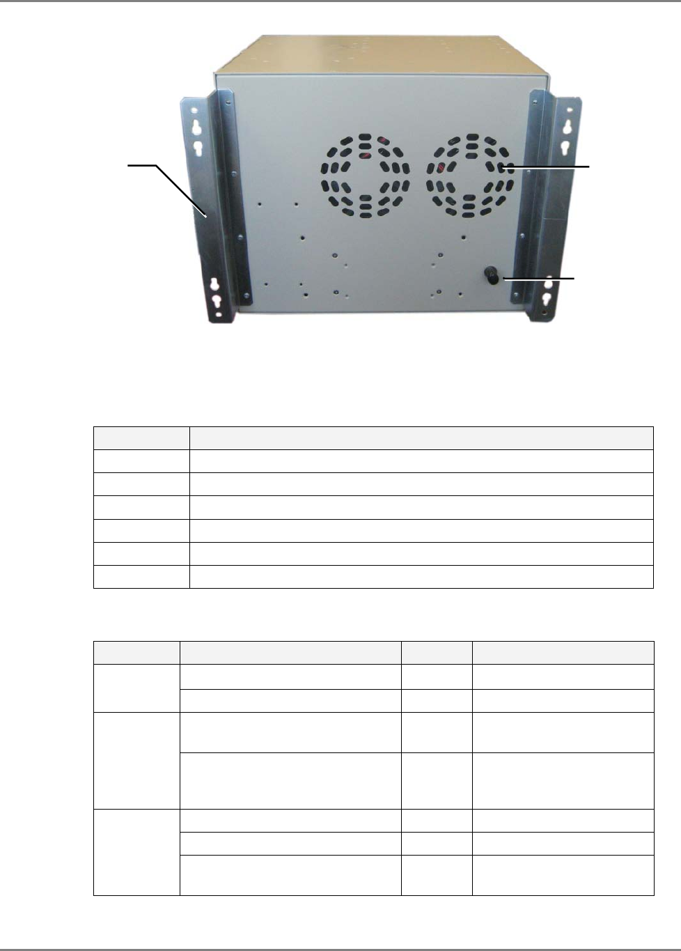
Figure 1-4. Example of Indoor HX Remote Unit rear View
The following tables provide a description of the HX indoor type connectors and LEDs.
Table 1-1. Connector Descriptions
Connector Description
F/O SC/APC fiber-optic connector for either SM or MM fibers
Antenna N-Type female 50Ω duplexed connector for RF antenna
AC PWR 110/220 VAC power feed
DC Direct 48VDC power feed
RS-232 Local craft connector
Grounding Grounding lug
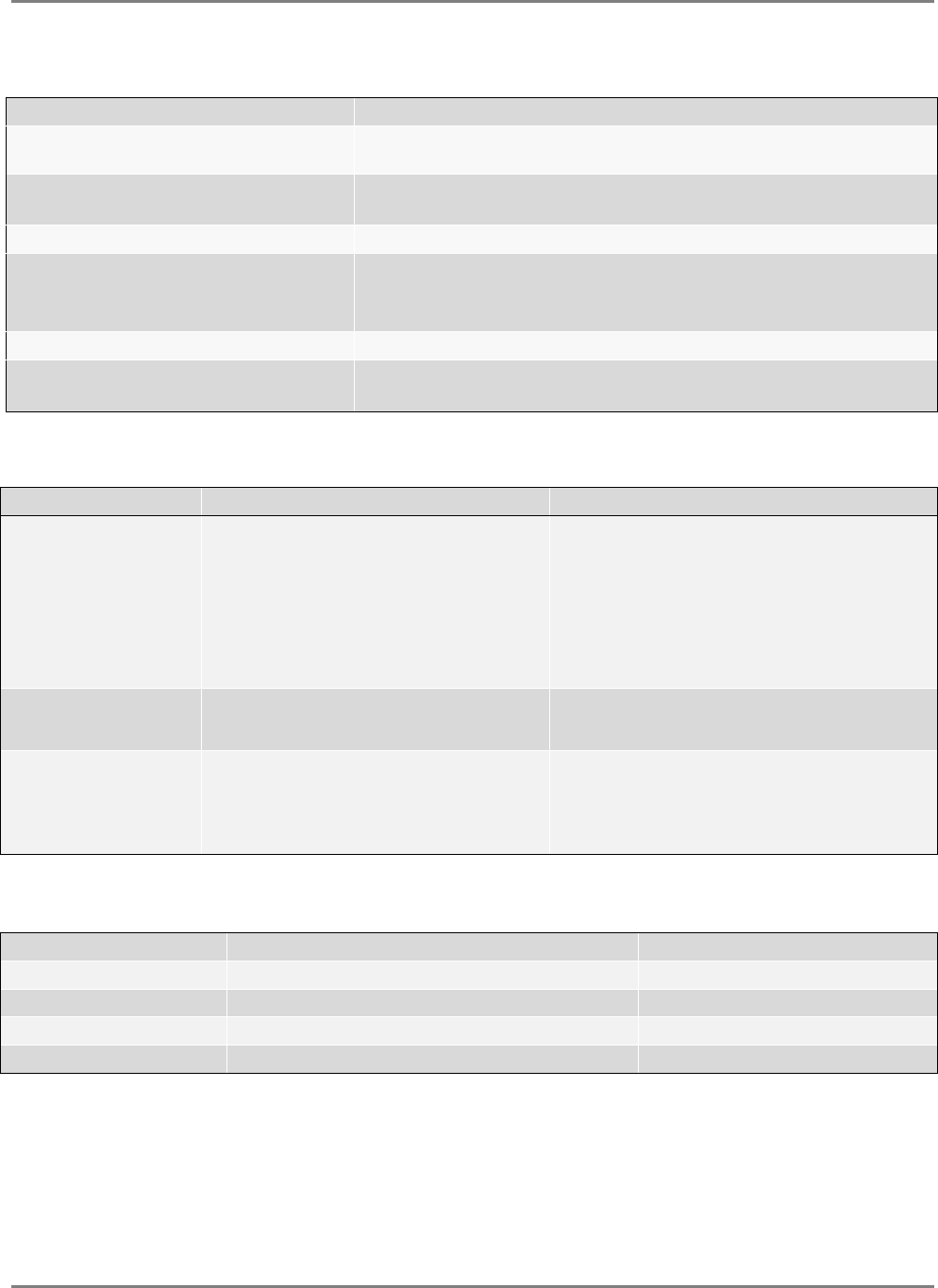
Table 1-2. LED Descriptions
Name Description Color Status
Power Device is powered GREEN Steady On
Power not supplied to the unit GREEN Off
Comm When connected and discovered
by an OPTM (BU) GREEN Blink per communication
attempt
When device is powered on but
no external communication is
received
GREEN Steady Slow Blink
Link No Optical link is present GREEN Off
Low optical link level from OPTM GREEN Blink
Normal optical link level from
OPTM GREEN Steady On
Grounding lug
Fans holes
Wall mount
brackets
System Installation Unpacking and Inspection
MobileAccessHX Installation and Configuration Guide 7
2
2
S
Sy
ys
st
te
em
m
I
In
ns
st
ta
al
ll
la
at
ti
io
on
n
This chapter describes the installation procedure for the MobileAccessHX Remote Unit. The
installation procedure differs according to the type of enclosure –Indoor or Outdoor.
2.1 Unpacking and Inspection
Unpack and inspect the cartons according to the following procedure
1. Open the shipping carton and carefully unpack each unit from the protective packing
material.
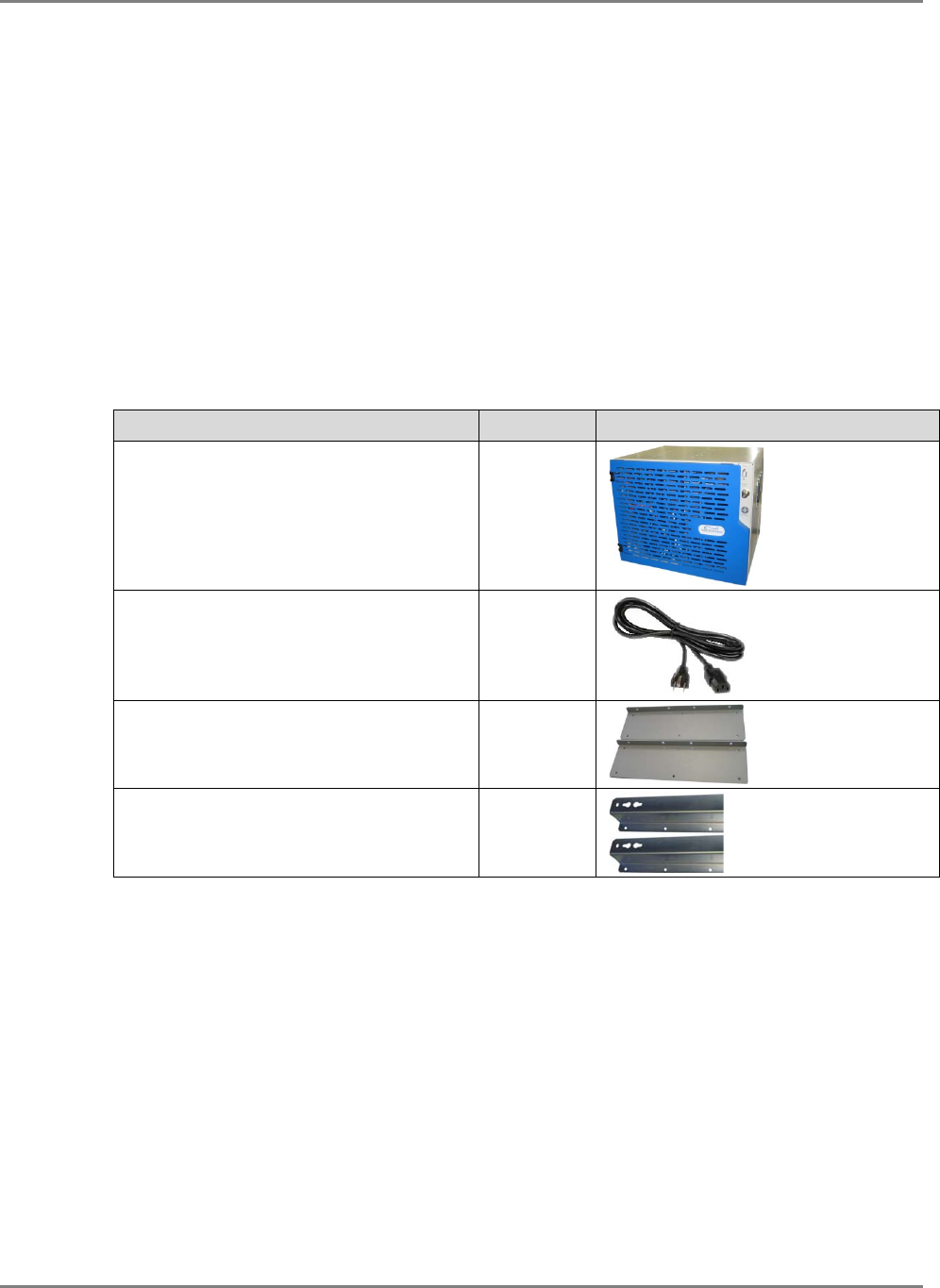
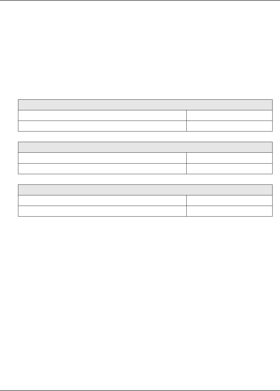
2. Verify that all the parts have been received:
Description Qty Item
HX Cabinet 1
For AC power models - AC power cord
Note: Image shown here is for example only
1
For rack mount installations– 19” rack
brackets (and cabinet assembly screws) 2 (R/L)
For wall mount installations – wall
bracket (and cabinet assembly screws). 2 (R/L)
3. Check for signs of external damage. If there is any damage, call your MobileAccess service
representative.
System Installation Mounting
MobileAccessHX Installation and Configuration Guide 8
2.2 Mounting
The HX indoor model installation requires two people and can be installed in one of the
following configurations:
• Wallmount - on the wall in the communication room
• Rackmount – in a 19” rack in the
communication room
allocated to that area.
General Installation Instructions
The Indoor type HX Remote Units unit should be installed in a communication room that
provides access to authorized personnel only. The units are maintenance free. In the event of
failure, only authorized personnel should handle the units.
• Environmental Data - Maximum ambient operating temperature: 50° C
• Maximum ambient temperature in a rack: 45° C
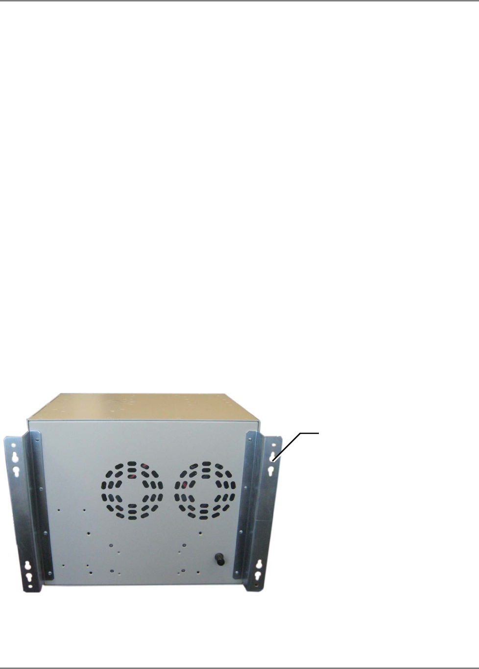
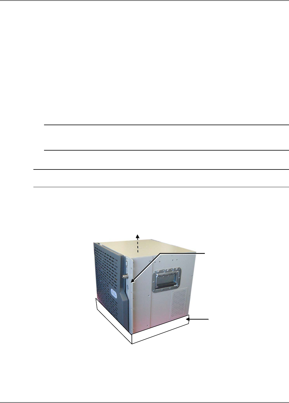
2.2.1 Wallmount Installation
The EXAMPLE is for CONCRETE walls (requires anchors McMaster-Carr catalogue number
92403A200, or equivalent).
To mount HX on wall
1. Assemble the WALL MOUNT BRACKETS (2) to the REAR PANEL of the HX cabinet using the
supplied screws (4 for each bracket).
2. Using the bracket holes as a guide, drill four holes (2 for each bracket) for concrete anchors.
3. Insert the anchors in the wall and hang the HX cabinet.
Figure 2-1. HX Indoor Unit with Assembled Wallmount Brackets
Holes for hanging HX
unit on anchors
System Installation Mounting
MobileAccessHX Installation and Configuration Guide 9
2.2.2 Rack Mount Installation
Rack Installation General Safety Instructions
Review the following guidelines to help ensure your safety and protect the equipment from
damage during the installation.
• Only trained and qualified personnel should be allowed to install or replace this
equipment.
• Verify that ambient temperature of the environment does not exceed 50°C (122°F)
• To maintain a low center of gravity, ensure that heavier equipment is installed near the
bottom of the rack and load the rack from the bottom to the top.
• Ensure that adequate airflow and ventilation within the rack and around the installed
components so that the safety of the equipment is not compromised. It is recommended
to allow for at least about 2 cm of airspace between devices in the rack.
NOTE: The cabinet requires a clearance of 10 cm above the unit. If a heating source is
installed beneath the HC cabinet, a buffer must be placed between the cabinet and the
surface.
To install HX unit in rack
NOTE: Plan the location of the unit in the rack. If there is a heat emmitting device located below
the unit, place a heat absorbent buffer between the HX cabinet and heat emitting device.
1. Assemble the RACK MOUNT BRACKETS (2) to the SIDE PANELS of the HX cabinet using the
supplied screws.
2. Mount in the 19” rack and secure with the supplied screws.
Figure 2-2. Example of Similar Indoor Cabinet with Rack Brackets and Heat Buffer
3. Heat absorbing buffer (not supplied) – in case of a heat emitting sources located below
unit.
10 cm clearance above
HX cabinet
Rack Brackets
(supplied screws)
Heat absorbing buffer
System Installation Connections
MobileAccessHX Installation and Configuration Guide 10
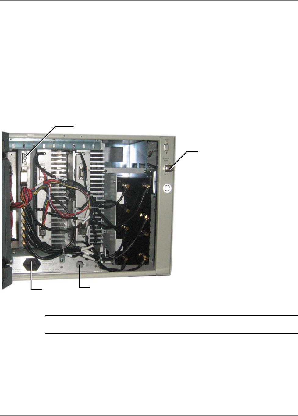
2.3 Connections
The HX main connections consist of the following:
• RF antenna
• Fiber Optic connection
• Power connections
Connect the HX Indoor unit as follows
1. Connect broadband ANTENNA coax to HX cabinet DUPLEXED ANTENNA port (external).
2. OPEN cabinet door.
3. Connect F/O cables to RHU optic port (internal).
NOTE: Keep in mind the rules for handling and connecting F/O cables. The F/O cables will
be connected to the associated BU in the communication room at a later phase.
• Install splice box near Remote Cabinet.
• Connect fiber optic cable to splice box and the SC/APC pigtails to the HX RHU module.
• For the downlink, connect the fiber optic cable pigtails from splice box coming from the
BU port to the corresponding RU port (routing the optic fibers so they will fit through the
top opening in the door.)
• For the uplink, connect the fiber optic cable pigtails from splice box from the RU (routing
the optic fibers so they will fit through the top opening in the door), to the uplink port
that connects to the BU.
Duplexed RF
antenna port
Fiber optic port on HX
RHU module
AC power
Location of
DC power
Figure 2-3. HX connections
System Installation Connections
MobileAccessHX Installation and Configuration Guide 11
Note: The internal power connections and other connections should already be connected.
4. Connect AC (cable supplied) or DC power according to your MODEL. (Unit should power-ON).
5. Verify that the RHU LEDs are GREEN:
• PWR and Link: Steady Green
• COMM: Blinking Green
If the LEDs are not as described above, refer to HX Unit Interfaces for troubleshooting.
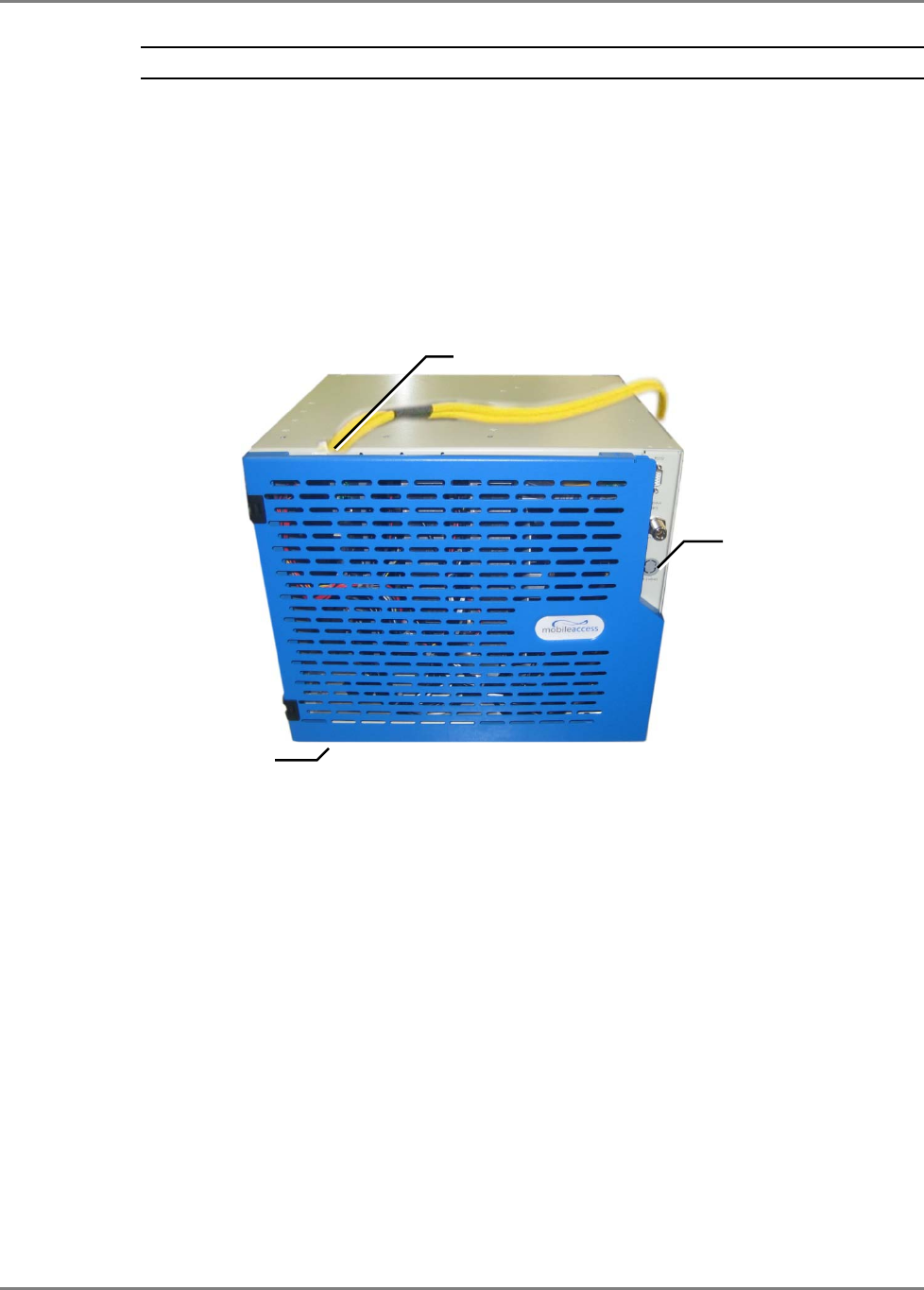
6. Route the fiber optic cables toward the TOP of the cabinet and the power cable towards the
bottom.
Figure 2-4. Closed HX Cabinet with Routed Cables
7. Close the cabinet door, routing the corresponding cables through the top and bottom
openings and lock the door.
Cabinet
lock
Routed fiber
optic cable
Route power cable
from under

Commissioning MA Head-End Initial Controller Setup
MobileAccessHX Installation and Configuration Guide 12
3
3
C
Co
om
mm
mi
is
ss
si
io
on
ni
in
ng
g
M
MA
A
H
He
ea
ad
d-
-E
En
nd
d
This section is relevant for installations in which an MA1000/2000 platform is NOT already
installed at the site. This section provides a description of how to configure the head-end units
required for HX operation which include the SC-450 Controller, RIU and Base Unit.
NOTE: This section does NOT describe the physical installation of the head-end units. The
physical installation is described in the corresponding Quick Installation Sheets or User Manuals.
3.1 Initial Controller Setup
NOTE: The available tabs and options may vary depending on the access level used to open your
session.
This section provides the details on the basic setup and configuration of the SC-450
management interface. It is to be completed after the physical installation of the controller and
connections to the relevant devices has been completed.
3.1.1 Open a Session to the Controller
1. Verify you computer is configured for a DHCP server:
NOTE: The procedure may differ depending on your specific Windows OS.
a. In the Local Area Connections choose Properties.
b. Select Internet Protocol (TCP/IP) Connection, choose Properties and define
for DHCP and automatic DNS server address acquisition as shown in following
figure. Click OK.
Commissioning MA Head-End Initial Controller Setup
MobileAccessHX Installation and Configuration Guide 13
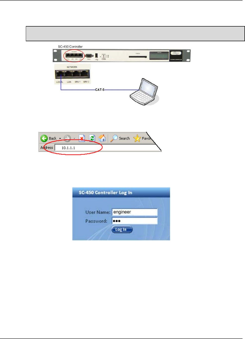
2. Connect the PC directly to the SC-450 LOCAL port via the supplied cross-cable cable as
illustrated below.
Warning!!! Do NOT connect the SC-450 LOCAL port to a network
as its DHCP server can disrupt LAN IP addressing.
Figure 3-1. Connect PC to the SC-450 Local Port
3. Open a Web browser and enter the SC-450 default address: 10.1.1.1.
The SC-450 has been optimized for use on IE 6.0 and Firefox 3.0 or higher. For proper
display on IE 8.0 use compatibility mode by selecting Tools -> Compatibility View Options
and Add the SC-450 website 10.1.1.1.
The Login dialog appears.
4. To open a session with configuration privileges, enter:
a. User Name: ‘engineer’
b. Default Password: ‘eng’
Supplied Ethernet
cross-cable
Commissioning MA Head-End Initial Controller Setup
MobileAccessHX Installation and Configuration Guide 14
3.1.2 IP Address Configuration
Set the SC-450 LAN port for remote control via
static or dynamic IP
address.
.
NOTE: Local setup and troubleshooting is performed via the SC-450 LOCAL port. In addition,
the Local port can be assigned
a static IP address
and connected to the customer LAN for
remote access capability.
To Configure SC-450 for Remote or Local Management
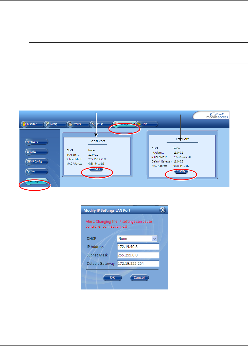
1. Access the GUI interface of the SC-450.
2. Select the Management tab and then click IP Settings on the side bar menu.
3. To change the LAN Port network settings, click the Modify button in the LAN Port
Configuration Area. The following dialog appears.
LAN Port
Configuration Area
LOCAL Port
Configuration Area
Commissioning MA Head-End Initial Controller Setup
MobileAccessHX Installation and Configuration Guide 15
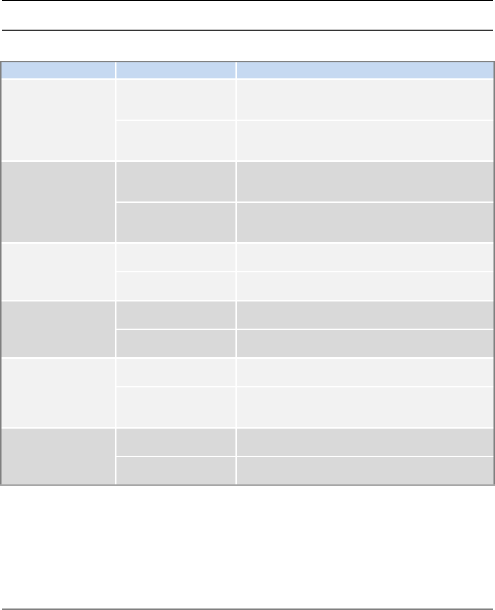
To Define… Do This…
Static IP Address Set DHCP as None.
Enter the IP Address, Subnet and Gateway.
Click OK.
Dynamic IP Address Set DHCP as Client and click OK.
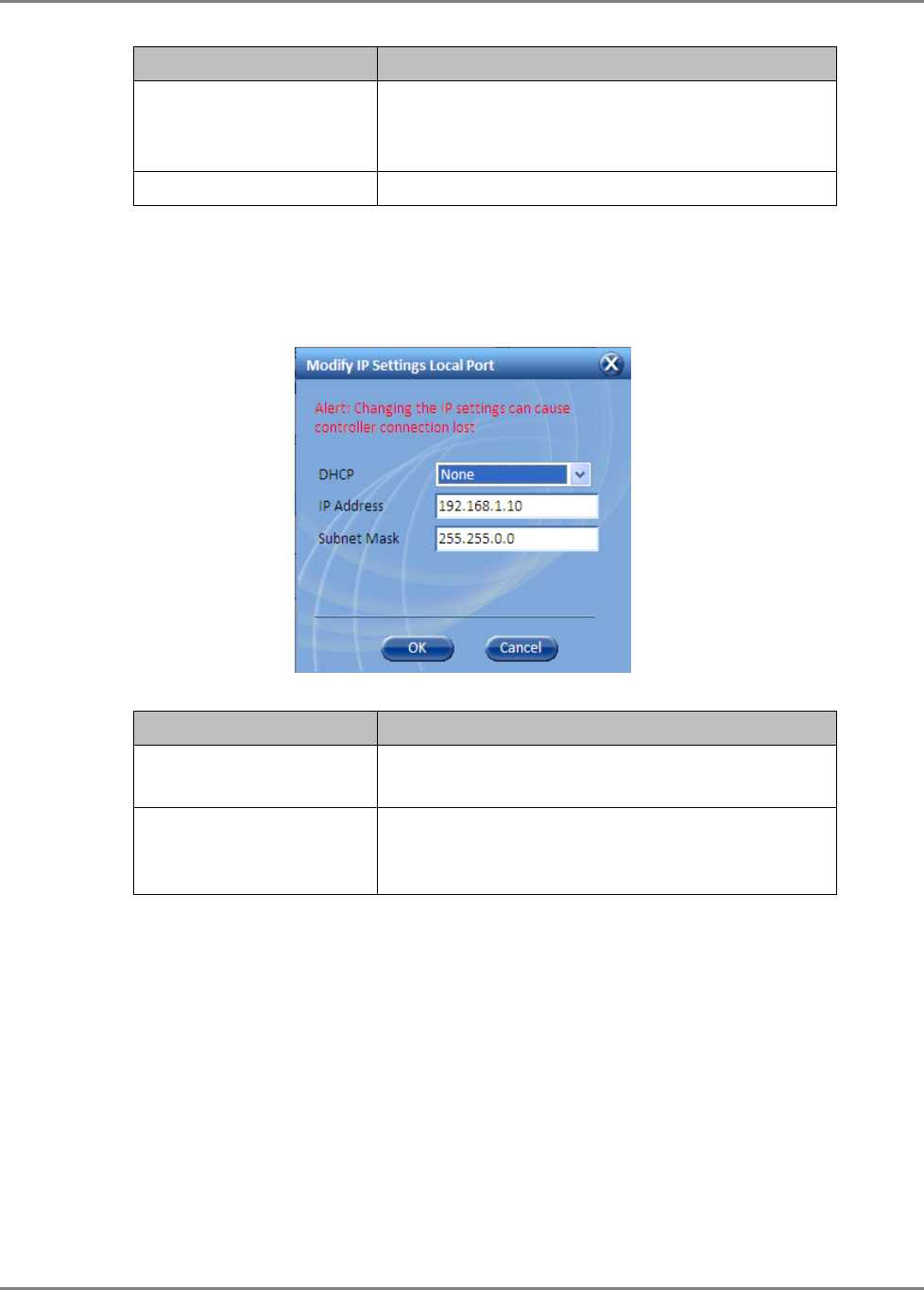
4. To change the LOCAL Port network settings, click the Modify button in the LOCAL Port
Configuration Area. The following dialog appears. The LOCAL Port configuration settings
are displayed on the SC-450 LCD.
To Define… Do This…
Static IP Address Set DHCP as None.
Enter the IP Address and Subnet. Click OK.
DHCP Server Set DHCP as Server and click OK.
WARNING!!! When using this setting, connect
ONLY directly to the PC – NOT to a network.
Commissioning MA Head-End Configure Controller Settings
MobileAccessHX Installation and Configuration Guide 16
3.2 Configure Controller Settings
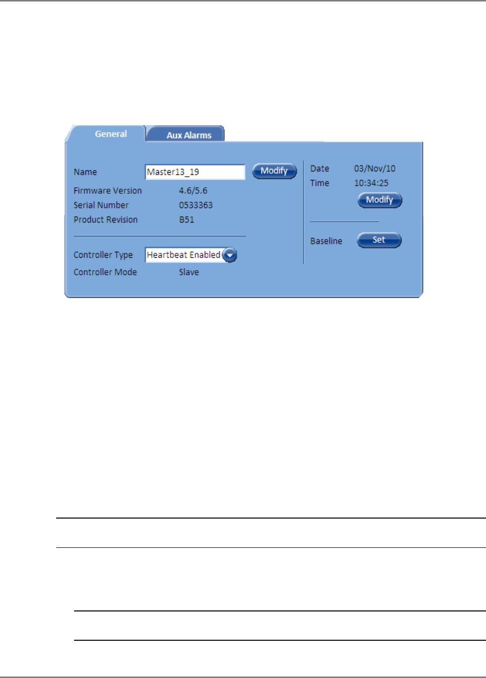
In the Network Topology, double-click on the controller item. The controller
General
tab is
displayed, where the Controller Mode is displayed as shown below.
Configure as follows:
1. In the General tab:
• Assign the controller a recognizable Name indicating its location or other.
• Verify that the correct Time and Date are set for the controller since events for devices
under this controller will be received with the set time and date.
• Set the Controller Type according to your system.
• Click the Base Line button. This sets
all
of
the MobileAccess devices currently displayed
in the Network Topology pane as a reference and will continue displaying them (in gray)
even if communication is lost with a device.
3.3 Device Configuration and Preparation
This procedure consists of two phases: configuration and preparation phase and adjustment
procedure.
NOTE: The available tabs and options in the SC-450 Web GUI may vary depending on the
access level used to open your session.
Phase I
1. Log-in to the SC-450. Refer to section 3.1.1 for details.
2. Verify that the Base Unit, RIU and HX units are displayed in the Network Topology tree.
NOTE: HX units are hosted by the BU and are detected every time the BU is powered-up or
reset from the Web GUI application.
Commissioning MA Head-End Device Configuration and Preparation
MobileAccessHX Installation and Configuration Guide 17
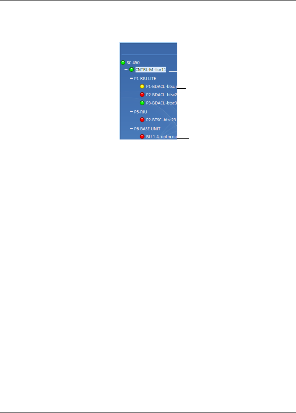
Verify that all the elements are displayed in the Network Topology pane under their
corresponding hosts, and are colored green, red, or yellow. Any of these colors are
acceptable before the adjustment procedure has been performed (following sections).
3. Verify that the BU is set to operate with RIU:
• Click on the BU item in the Network Topology Tree Select RF Parameters Tab
from the Work Area Interface Type to MA RIU
• Optional: Assign the BU an identifiable name by Modifying the Name parameter in the
Module Info tab
4. Using a Fiber Optic Tester, verify that the UL Optical Link Level of the fiber connected to the
BU is >0
• Set the Fiber Optic Tester to a wavelength of 1310nm
• Unplug the UL fiber connection from the BU and test to make sure it is at a level >0
• If the level is not >0, clean the fiber and retest
5. Set up CW signal to be connected to the signal conditioner (BTSC/BDAC). The 700 MHz LTE
conditioner does not need an external CW signal (See Section 3.3.3).
• BTSC acceptable input power range = +10 to +36dBm
• BDAC acceptable input power range = -16 to +10 dBm
• Acceptable frequency range depends upon the RF service
6. Adjust the signal conditioner (BTSC/BDAC) with the CW signal. The 700 MHz LTE conditioner
does not need an external CW signal. (See Section 3.3.3).
• Connect the CW signal to the BTSC/BDAC DL Port or Duplex port located on the rear of
the RIU associated with the slot that the signal conditioner (BTSC/BDAC) is inserted into
• Click on the conditioner in the Network Topology Tree Select RF Parameters Tab from
the Work Area Adjust Max Input Power by clicking on the Adjust button in the DL
Power section Select Use Current Input Power
• After a few moments, verify that the Target Max Input Power and the Current Input
Power are equivalent
7. Repeat Step 6 for each signal conditioner
8. Perform a Quality and Integrity Check of the installed system as per the RF Design and
Statement of Work. Contact a MobileAccess Project Manager for more instructions.
Phase II
These Phase II steps should only be performed after completing Phase I of the commissioning
process.
BTSC Modules
Controller Element
OPTM (BU) Modules

Commissioning MA Head-End Device Configuration and Preparation
MobileAccessHX Installation and Configuration Guide 18
NOTE: Please consult a MobileAccess certified installer on the details of these steps or access the
MobileAccess Partner Portal for more information.
1. Perform an Emulated Adjustment
2. Perform UL Noise Mitigation
Commissioning MA Head-End RIU Configuration
MobileAccessHX Installation and Configuration Guide 19
3.4 RIU Configuration
There are two types of RIU configuration procedures:
• Configuration for all BTSC modules except for LTE 700
• Configuration for BTSC 700 module
3.4.1 Configuration for all BTSCs (other than LTE 700)
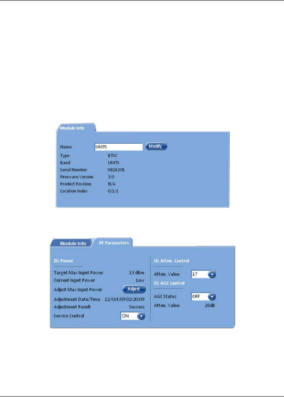
Perform this procedure for each RIU module (BTSC/BDAC):
1. Double-click on the BTSC item in the Network Topology. The BTSC configuration dialog
appears.
2. Assign the BTSC an identifiable name (i.e. operator name), by clicking the Modify button
and typing the name.
3. Click on the RF Parameters tab.
4. Verify that Service Control is ON.
5. Set DL AGC Control to ON. (OFF – Disables automatic gain control.)
6. (Do NOT modify the UL Atten. Value – this is factory set and should NOT be modified
unless unique conditions exist.)
Commissioning MA Head-End RIU Configuration
MobileAccessHX Installation and Configuration Guide 20
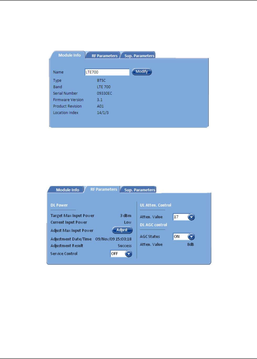
3.4.2 BTSC LTE 700 MHz
To Configure and Control the MobileAccess BTSC LTE 700 MHz
1. Double-click on the LTE BTSC item in the Network Topology. The LTE BTSC
configuration dialog appears with the Module Info tab displayed by default.
This tab provides general information such as software and hardware versions, type and
serial number of the LTE BTSC.
2. Assign the BTSC LTE 700 MHz an identifiable name (i.e. operator name), by clicking the
Modify button and typing the name.
3. Click on the RF Parameters tab, the following tab is displayed.
This tab shows information on the RF parameters, and provides service and RF signal control
options.
4. To control the service supported by this BTSC choose an option in the Service Control
field:
• ON – Enables Service
• OFF – Disables Service
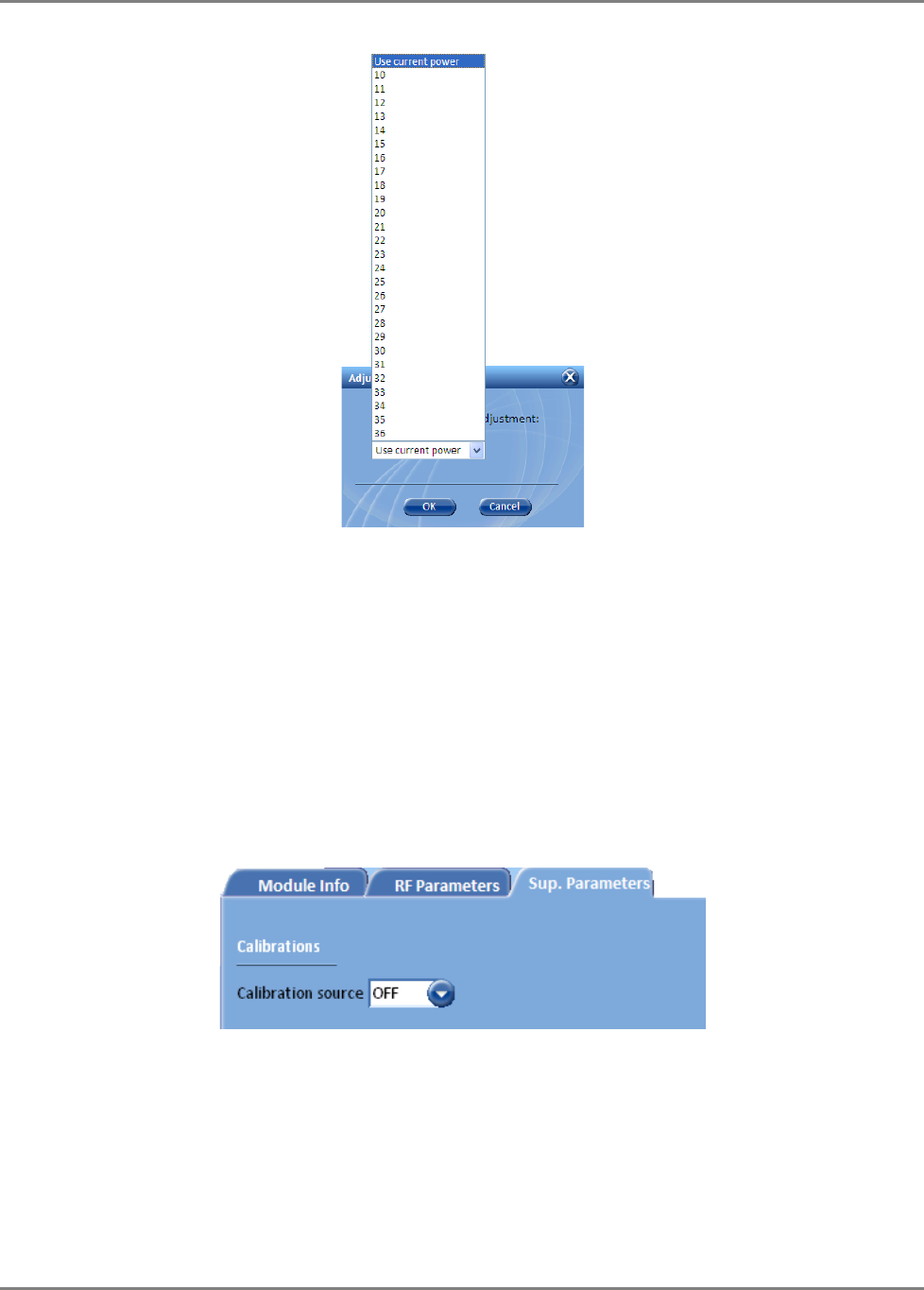
5. Under DL Power section of the tab, click Adjust and select the required value (dBm) and click OK.
Commissioning MA Head-End RIU Configuration
MobileAccessHX Installation and Configuration Guide 21
6. The DL power gain may be set automatically (AGC) or manually (DCA – Digital Control
Attenuation). To control the DL gain control, set the DL AGC Status:
• ON – Enables automatic gain control to compensate for input power variations. When
enabled, gain control is performed automatically.
• OFF – Disables automatic gain control and enables DCA to be set manually (DL DCA
Manual Override Value).
7. UL Atten. Value – Controls attenuation on the uplink. This value is set during
manufacturing and should be modified only under special circumstances.
8. Sup. Parameters tab – Relevant only for the initial adjustment procedure of the complete
system (See LTE addendum document:
UMA_MA1000 MA2000_700MHz LTE AO
). Otherwise
disregard.
This option provides an internal signal generation source that can be used during the
adjustment procedure instead of connecting an external signal generator.
• ON – Internal signal source activated.
• OFF – Internal signal source disabled.
Commissioning MA Head-End Base Unit Configuration Dialog
MobileAccessHX Installation and Configuration Guide 22
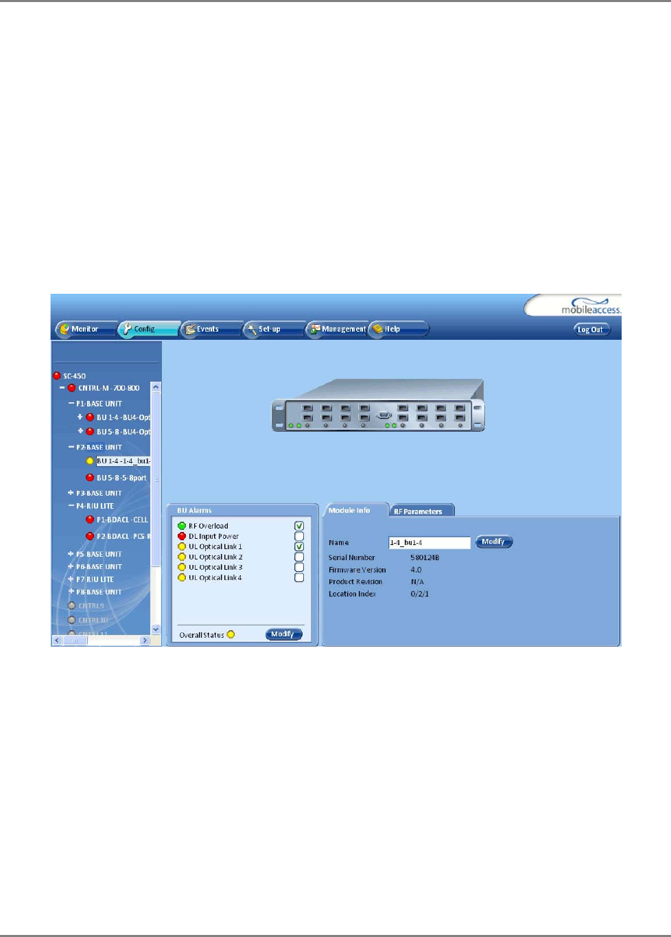
3.5 Base Unit Configuration Dialog
The configuration dialog consists of two tabs: Module Info and RF parameters. The main
provided functions are:
• In the Module Info tab - Viewing basic information on the unit and assigning the unit an
identifiable name.
• In the RF Parameters tab - Setting gain control, resetting the Base Unit (required when an
RHU is added) and monitoring the downlink signal.
To Configure and Control the Base Unit:
1. Double-click on the Base Unit item in the Network Topology. The Base Unit configuration
dialog appears.
2. In the Module Info tab click the Modify button and assign the BU an identifiable name
that indicates the technology to which it interfaces.
3. Click the RF Parameters tab.
Commissioning MA Head-End Base Unit Configuration Dialog
MobileAccessHX Installation and Configuration Guide 23
Set the following parameters:
• Interface Type – RF Source interface type (i.e. MA RIU, Other)
• AGC Status – Sets DL AGC mode:
ON – Automatic gain control to compensate for input power variations. When enabled,
gain control is performed automatically.
OFF - DCA can be set manually (DL DCA Manual Override Value).
• UL Atten. Value – Controls attenuation on the uplink. This value is set during
manufacturing and should be modified only under special circumstances.
Provisioning the MobileAccessHX Accessing HX Management Options
MobileAccessHX Installation and Configuration Guide 24
4
4
P
Pr
ro
ov
vi
is
si
io
on
ni
in
ng
g
t
th
he
e
M
Mo
ob
bi
il
le
eA
Ac
cc
ce
es
ss
sH
HX
X
Once the required physical connections have been completed, the HX unit is automatically
detected (auto-discover) by the SC-450 and can be remotely monitored and managed.
The MobileAccessHX Remote Unit is centrally managed via the MobileAccess SC-450 Controller.
Note that MobileAccessHX is not connected directly to the controller. It is connected to the Base
Unit (that is connected to the controller). Thus, the controller monitors views and manages the
HX via the Base Unit to which the HX is connected.
Note: The provisioning procedure consists of two simple steps: assign the unit name (Module
Info tab) and click the Adjust button (Adjustment tab). Additional configuration options are
available as well.
Each HX unit can be managed via several dedicated panes that are accessed by clicking the
relevant HX item in the SC-450 Topology Tree.
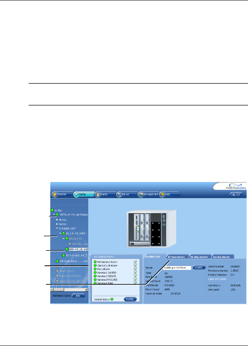
4.1 Accessing HX Management Options
To access the MobileAccessHX management options
In the Network Topology tree, expand the relevant Controller item, expand the relevant
Base Unit (to which the HX is connected) and click on the HX. The HX alarms and management
tabs appear.
The HX Cabinet Alarms are continuously displayed (to the left of the tabs). The monitoring
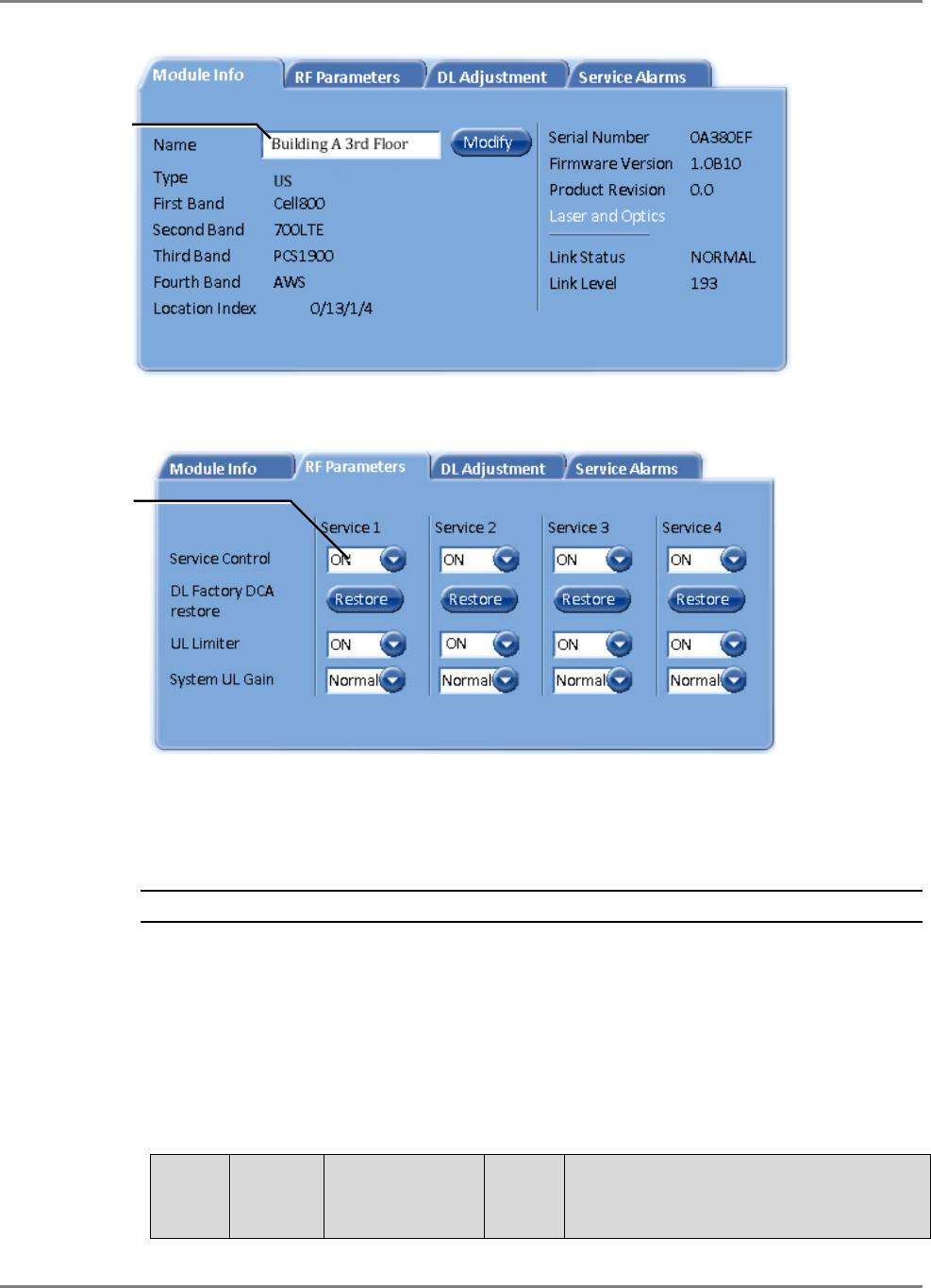
and configuration options are distributed over four tabs:
• Module Info - device version and identification definitions
• RF Parameters – service control options.
HX item
Host Base Unit
HX Alarm
status
Four management
tabs
Controller
Provisioning the MobileAccessHX Basic Setup Procedure
MobileAccessHX Installation and Configuration Guide 25
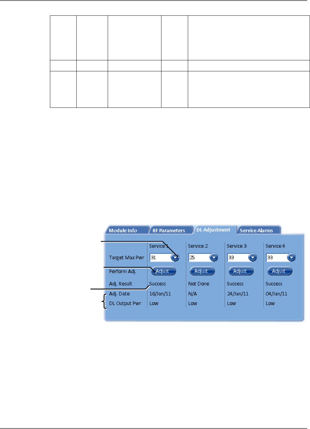
• RF Adjustment – provides the adjustment options.
• Service Alarms – used for masking redundant alarms
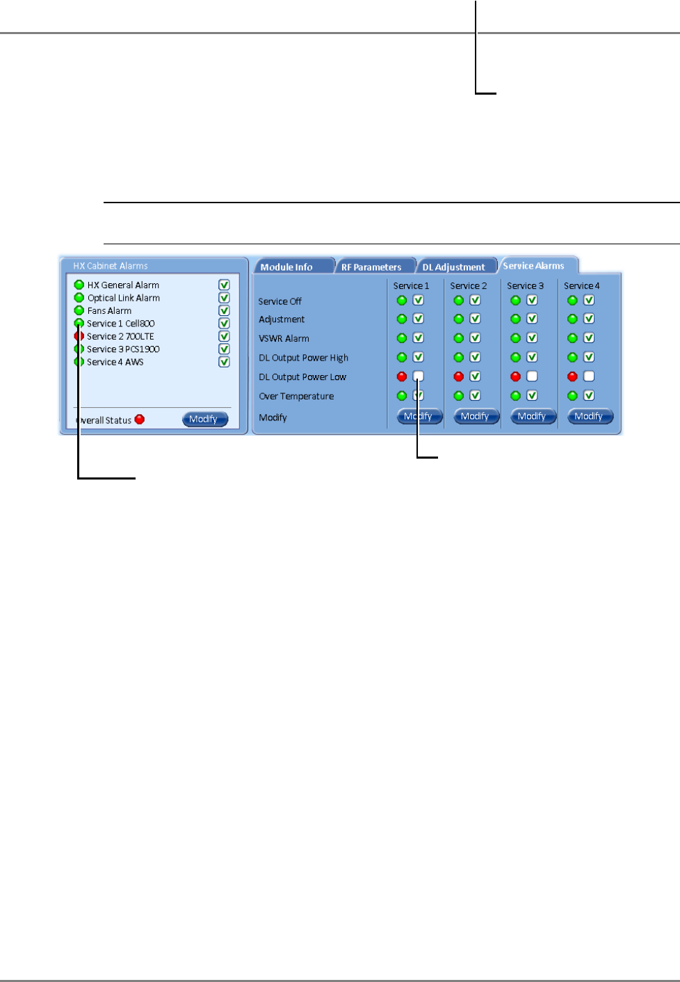
4.2 Basic Setup Procedure
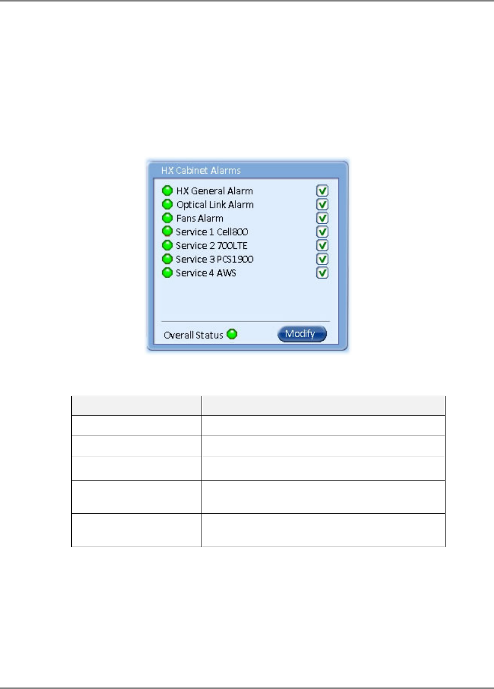
To perform basic setup
1. Verify that the alarms show green in the following tabs:
• HX Cabinet Alarms – displays system level alarms
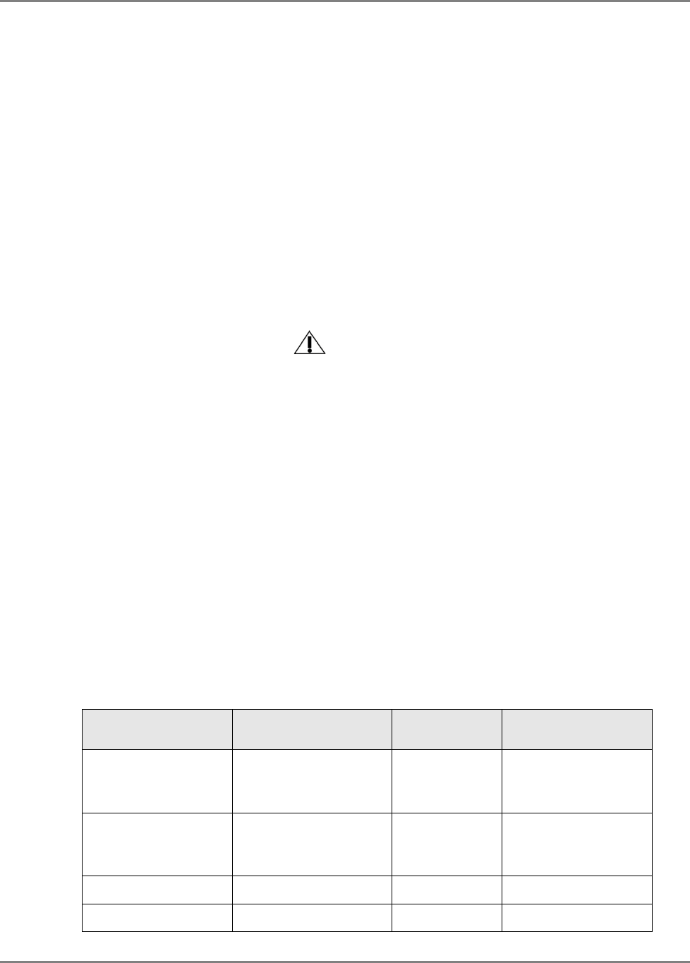
The following table provides a description of the device alarms shown above.
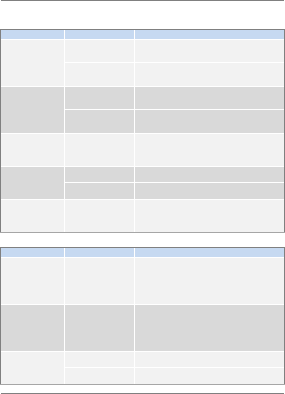
Table 4-1. HX Alarms Description
Alarm Description
HX General Alarm N/A
Optical Link Alarm Low optical level from BU (link level < 56)
Fans Alarm Faulty fans
Service 1/2/3/4 Summary of all port x / PA x monitored parameters
displayed in the
Service Alarms
sub-tab
Overall status Calculated according to its active alarms –
corresponds to highest alarm level detected.
Provisioning the MobileAccessHX Basic Setup Procedure
MobileAccessHX Installation and Configuration Guide 26
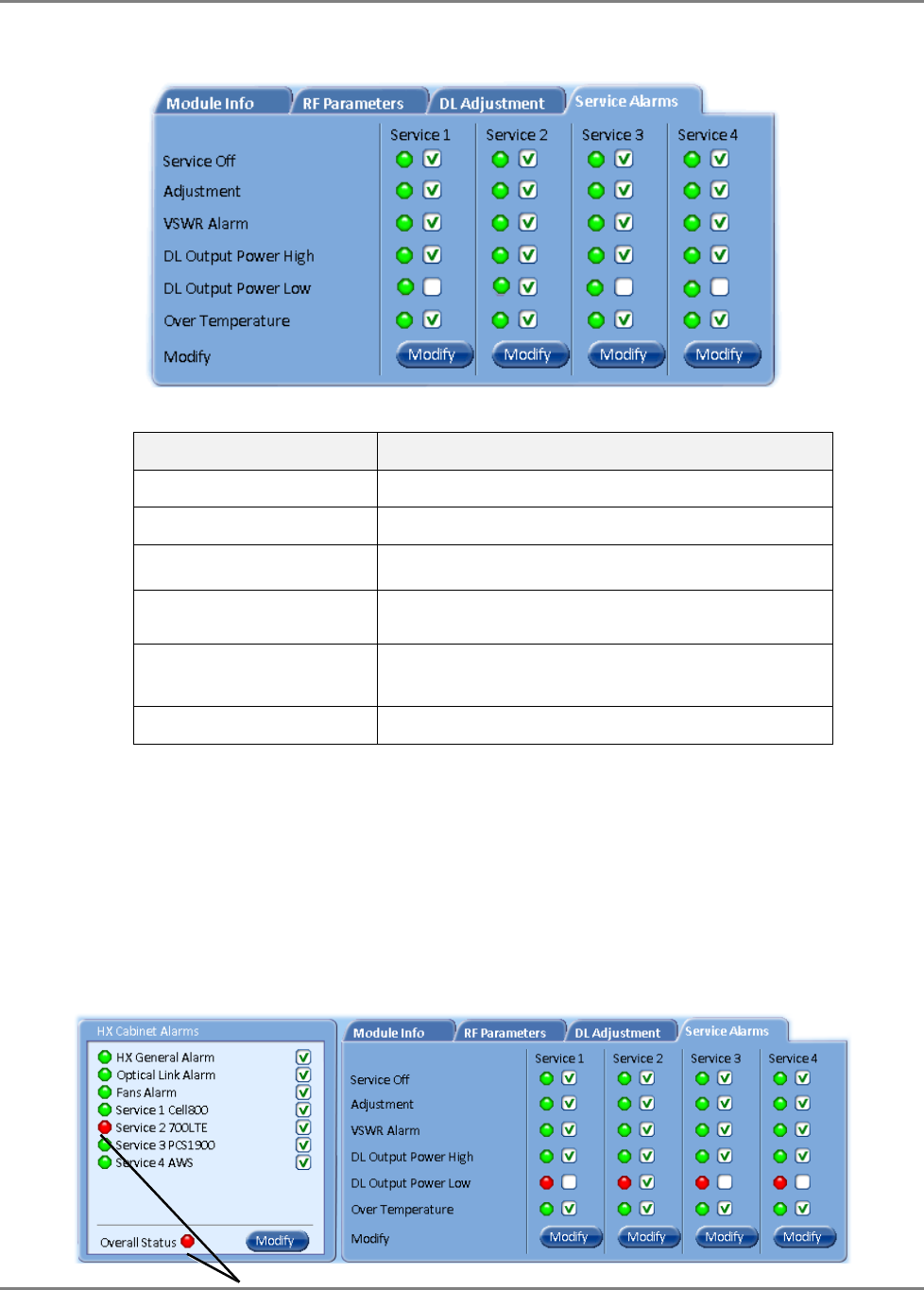
• Service Alarms – displays specific alarms for each supported service.
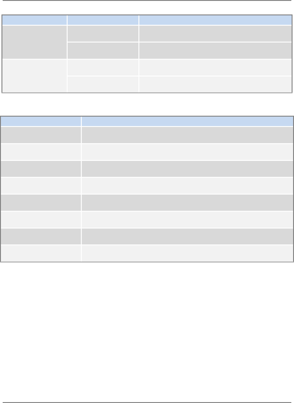
Table 4-2. HX Service Alarms Description
Alarm Description
Service Off Service disabled by the User
Adjustment Adjustment for target DL Output Power
VSWR Alarm Antenna disconnected (VSWR > 5:1)
DL Output Power High DL Output Power > “Target Adjustment value” +
2dB
DL Output Power Low DL Output Power < “Target Adjustment value” 1
15dB
Over Temperature Ambient temperature inside the HX unit >65°C
2. Mask irrelevant alarm conditions, in both tabs via the Modify button, to avoid having them
reflected overall status of the HX unit (displayed in the
HX Alarms
area).
For Example
In the example below, the
HX Cabinet Alarms
dialog shows the alarm response if the Service
2 DL Output Power Low alarm is NOT masked (enabled). In that case the
Service 2
and
Overall Status
will be RED indicating a fault.
Provisioning the MobileAccessHX Basic Setup Procedure
MobileAccessHX Installation and Configuration Guide 27
If the Service 1 alarm is MASKED (Disabled), then the LED for the alarm will be RED; but,
the corresponding Service alarm in
HX Cabinet Alarms
area will be GREEN – showing NO
Fault.
Note: The Overall Status alarm will only show green if all of the generated alarms are
masked (or if all alarms are green).
In the figure above the alarm condition for (Service 1) “DL Output Power Low” actually
exists, while the masking prevents this condition from affecting the overall status of the
service and therefore the Service 1 led in
HX Cabinet
Alarms area is green.
3. Assign the unit a recognizable name (i.e. corresponding to its location):
In the Module Info tab, click the Modify button, enter the required text and click OK. The
assigned name will be displayed.
Unmasked alarm
RED - Unmasked alarm reflects on
corresponding Service alarm and
Overall Status
Masked alarm
GREEN - Masked DL Output Power Low
alarm (for Service 1) alarm does not
reflect on corresponding Service alarm
in
HX Cabinet Alarms
area.
Provisioning the MobileAccessHX Basic Setup Procedure
MobileAccessHX Installation and Configuration Guide 28
4. Click the RF Paramaters tab.
5. In the DL Adjustment tab:
Verify the following:
• All required services (e.g. Cell 800, 700 LTE, etc.) are enabled (Default = On)
• UL Limiter is enabled (Default = On)
NOTE: DL Factory DCA Restore – DO NOT click Restore button unless DL adjustment fails.
6. Verify that the System UL Gain is set to default configuration (i.e. Normal). See following
table for Description of System UL Gain values.
Field
Value UL
Gain
(dB)
UL Limiter
Threshold
(dBm)
NF
Type
(dB)
Case Scenario
User assigned
name
Services enabled
Provisioning the MobileAccessHX Basic Setup Procedure
MobileAccessHX Installation and Configuration Guide 29
Low 1 -30 13 Set in cases where mobile stations are
very near to the HX antenna (e.g. in
cases where HX unit antenna port is
splitted to multiple lower power antennas
to cover standard office building)
Normal 11 -40 10 Default – for standard HX installations
High 21 -50 7 Set in cases where mobile stations are
located far from the HX antenna (e.g. in
a parking lot, where the HX unit is
mounted high on a pole).
* Max. NF = Typical NF + 4dB
7. In the DL Adjustment tab, perform DL adjustment manually to complete the commissioning
procedure.
• Set the Target Max Pwr (Target Pout) value according to site planning requirements.
Default Target Max Power value is the maximum value per each band (e.g. 33 dBm for
700LTE band).
• DL Output Power can be adjusted to a lower level (up to 10dB lower) as required.
• Click the Adjust button.
• Confirm that the adjustment procedure is successful (Adjust Result shows “Success”)
and verify actual readings of Adj. Date and DL Output Pwr .
If adjustment procedure fails, refer to the RF Parameters tab, click the Restore
button and perform adjustment again.
THE HX SETUP PROCEDURE IS NOW COMPLETE
Click to select
Target Max Power
Click to perform RF adjustment
according to Target Max Power
Verify successful results
Adjustment Date and Actual
DL Pwr reading

MobileAccessHX Installation and Configuration Guide 30
A
Ap
pp
pe
en
nd
di
ix
x
A
A:
:
S
Sy
ys
st
te
em
m
S
Sp
pe
ec
ci
if
fi
ic
ca
at
ti
io
on
ns
s
RF Parameters
RF Frequency Range
Services Band Frequency Range
Uplink Downlink
CDMA / WCDMA** / TDMA / GSM CELL800 824-849 869-894
CDMA / WCDMA** / TDMA / GSM PCS1900 1850-1915 1930-1995
WCDMA** / HSPA AWS2100 1710-1755 2110-2155
LTE 700 MHz 698-716 and
776-787 728-757
GSM / GPRS / WCDMA / HSPA / LTE * EGSM900 880-915 925-960
GSM / GPRS / WCDMA / HSPA / LTE* DCS1800 1710-1785 1805-1880
WCDMA / HSPA / LTE* UMTS2100 1920-1980 2110-2170
(*) WCDMA service is based on 3GPP standards, LTE service may be deployed in the future due to frequencies re-farming planned by the
Carriers
(**) WCDMA service is based on 3GPP2 CDMA2000 standards.
Appendix A: System Specifications
MobileAccessHX Installation and Configuration Guide 31
RF Parameters per Service
MobileAccessHX RF Parameters
MobileAccessHX
RF Parameter
LTE
700 MHz
CELL TDMA
/ CDMA /
WCDMA
800 MHz
PCS
CDMA /
WCDMA
1900 MHz
UMTS and
AWS CDMA/
WCDMA
2100 MHz
GSM /
E-GSM
900 MHz
DCS
1800 MHz
UMTS
2100 MHz
DL UL DL UL DL UL DL UL DL UL DL UL DL UL
Max Output Power:
1 Carrier (Composite) 33 33 33 33 29 32 33
2 Carriers 30 30 30 30 26 29 30
4 Carriers 27 27 27 27 23 26 27
8 Carriers - 24 24 24 20 23 24
12 Carriers - 22 22 22 17 21 22
24 Carriers - 19 19 19 14 18 -
Mean Gain (dB)1 33 11 33 11 33 11 33 11 29 11 32 11 33 11
Pin (dBm) 1 0 0 0 0 0 0 0
Input IP3 (dBm) AGC
ON 16 16 16 16 16 16 16
Input IP3 (dBm) AGC
OFF Typical -10 -10 -10 -10 -10 -10 -10
Max Intermod
Distortion (dBm) -13** -13* -13* -13* -36* -30* -13*
NF (dB) Typical 10 10 10 10 10 10 10
VSWR 1.5:1
Gain Flatness/Ripple
(dB)2 +/-1.03 +/-1.5 +/-2.0 +/-1.5
* WCDMA compiles with 3GPP TS 25.106 V5.0.0 (2002-03) table 9.4 spectrum emission mask.
** Out of band and spurious emissions compliant to FCC.
1Factory set mean gain BU-HX without RIU. May be field adjusted using controller system.
2Gain Flatness/Ripple is specified for the non-duplexed port of the system.
3Gain Flatness/Ripple at any block of the spectrum.
Appendix A: System Specifications
MobileAccessHX Installation and Configuration Guide 32
Optical Specifications
Optical Output Power <3.0mW
Max. Optical Budget 2 dB for fiber + 1 dB for connectors (assumed) = 3 dB total. 300 m Multi-
mode
Optical Loss per Mated-pair Connectors 0.5dB (max)
Optical Connector SC/APC
Fiber Type
Single-mode: 9/125um
Multi-mode: 50/125 um or 62.5/125um (Minimum qualifications with
ANSI/TIA/EIA-568-B series, EN50173-1 or ISO/IEC 11801)
Wavelength 1310±10nm
Maximum Distance Between Base Unit and
Remote Cabinet
2km for SMF
300m for MMF
Physical Specifications – MobileAccessHX Remote Unit
Indoor Remote Unit Outdoor Remote Unit
Ports
(1) SC/APC fiber-optic pair connector
(1) N-Type female 50Ω connector for
antenna
(1) Power connector for 110/220VAC
power feed or (4) Power connectors for up
to (4) direct 48VDC power feeds
(1) D-Type 9 pins RS-232 connector for
local craft
(1) SC/APC fiber-optic pair connector
(1) N-Type female 50Ω connector for antenna
(1) Power connector for 110/220VAC power feed
or (4) Power connectors for up to 4 direct
48VDC power feeds
(1) D-Type 9 pins RS-232 connector for local
craft
Power Local Power (AC) or Remote DC power
feed options: 90-264 V AC or 36-75V DC
Max Power Consumption: 350W
Local Power (AC) or Remote DC Power feed
options: 90-264 V AC or 36-75V DC
Max Power Consumption: 350W
Physical Dimensions
Mounting: Wall or Rack
Dimensions: 43cm x 38cm x 35cm (16.9” x
14.9” x 13.8”) [X,Y,Z]
Weight (4 Services configuration): 32Kg
(71 lb)
Mounting: Wall or Poll
Dimensions: 43cm x 63cm x 30cm (16.9” x 24.8”
x 11.8”) [X,Y,Z]
Weight (4 Services configuration): 52Kg (114 lb)
Environmental Specifications
Indoor Remote Unit Outdoor Remote Unit
Operating Temperature 0°C to +50°C (32°F to 122°F) -10°C to +50°C (14°F to 122°F)
Storage Temperature -20°C to 85°C (-4°F to 185°F) -20°C to 85°C (-4°F to 185°F)
Humidity 10% to 95%, non-condensing -
Ingress Protection - IP65
MobileAccessHX Installation and Configuration Guide 33
A
Ap
pp
pe
en
nd
di
ix
x
B
B:
:
O
Or
rd
de
er
ri
in
ng
g
I
In
nf
fo
or
rm
ma
at
ti
io
on
n
NOTE: The information listed below is updated up to the document publishing date. Refer to the
MobileAccessHX datasheet for the most updated ordering information.
MobileAccessHX Remote Units
US Services, Indoor Units
Service Supported Part Number Description
CELL/PCS/700LTE/AWS
HX-C85P19L70A17-AC-A MobileAccessHX Quad-service indoor CELL, PCS, AWS,
and 700 MHz LTE solution supporting local AC power,
SMF and MMF.
HX-C85P19L70A17-DC-A MobileAccessHX Quad-service indoor CELL, PCS, AWS,
and 700 MHz LTE solution supporting remote DC
power, SMF and MMF.
CELL/PCS/700LTE
HX-C85P19L70-AC-A MobileAccessHX Tri-service indoor CELL, PCS, and 700
MHz LTE solution supporting local AC power, SMF and
MMF.
HX-C85P19L70-DC-A MobileAccessHX Tri-service indoor CELL, PCS, and 700
MHz LTE solution supporting remote DC power, SMF
and MMF.
CELL/PCS/AWS HX-C85P19A17-AC-A MobileAccessHX Tri-service indoor CELL, PCS, and AWS
solution supporting local AC power, SMF and MMF.
HX-C85P19A17-DC-A MobileAccessHX Tri-service indoor CELL, PCS, and AWS
solution supporting remote DC power, SMF and MMF.
CELL/PCS HX-C85P19-AC-A MobileAccessHX Dual-service indoor CELL and PCS
solution supporting local AC power, SMF and MMF.
HX-C85P19-DC-A MobileAccessHX Dual-service indoor CELL and PCS
solution supporting remote DC power, SMF and MMF.
AWS/700LTE
HX-A17L70-AC-A MobileAccessHX Dual-service indoor AWS and 700 MHz
LTE solution supporting local AC power, SMF and MMF.
HX-A17L70-DC-A MobileAccessHX Dual-service indoor AWS and 700 MHz
LTE solution supporting remote DC power, SMF and
MMF.
PCS/AWS HX-P19A17-AC-A MobileAccessHX Dual-service indoor PCS and AWS
solution supporting local AC power, SMF and MMF.
HX-P19A17-DC-A MobileAccessHX Dual-service indoor PCS and AWS
solution supporting remote DC power, SMF and MMF.

Appendix B: Ordering Information
MobileAccessHX Installation and Configuration Guide 34
MobileAccessHX Remote Units
US Services, Outdoor units
Service Supported Part Number Description
CELL/PCS/700LTE/AWS
HX-C85P19L70A17-AC-B MobileAccessHX Quad-service outdoor CELL, PCS,
AWS, and 700 MHz LTE solution supporting local AC
power, SMF and MMF.
HX-C85P19L70A17-DC-B MobileAccessHX Quad-service outdoor CELL, PCS,
AWS, and 700 MHz LTE solution supporting remote DC
power, SMF and MMF.
CELL/PCS/700LTE
HX-C85P19L70-AC-B MobileAccessHX Tri-service outdoor CELL, PCS, and
700 MHz LTE solution supporting local AC power, SMF
and MMF.
HX-C85P19L70-DC-B MobileAccessHX Tri-service outdoor CELL, PCS, and
700 MHz LTE solution supporting remote DC power,
SMF and MMF.
CELL/PCS/AWS
HX-C85P19A17-AC-B MobileAccessHX Tri-service outdoor CELL, PCS, and
AWS solution supporting local AC power, SMF and
MMF.
HX-C85P19A17-DC-B MobileAccessHX Tri-service outdoor CELL, PCS, and
AWS solution supporting remote DC power, SMF and
MMF.
CELL/PCS HX-C85P19-AC-B MobileAccessHX Dual-service outdoor CELL and PCS
solution supporting local AC power, SMF and MMF.
HX-C85P19-DC-B MobileAccessHX Dual-service outdoor CELL and PCS
solution supporting remote DC power, SMF and MMF.
AWS/700LTE
HX-A17L70-AC-B MobileAccessHX Dual-service outdoor AWS and 700
MHz LTE solution supporting local AC power, SMF and
MMF.
HX-A17L70-DC-B MobileAccessHX Dual-service outdoor AWS and 700
MHz LTE solution supporting remote DC power, SMF
and MMF.
PCS/AWS HX-P19A17-AC-B MobileAccessHX Dual-service outdoor PCS and AWS
solution supporting local AC power, SMF and MMF.
HX-P19A17-DC-B MobileAccessHX Dual-service outdoor PCS and AWS
solution supporting remote DC power, SMF and MMF.
Appendix B: Ordering Information
MobileAccessHX Installation and Configuration Guide 35
MobileAccess HX Remote Units
Non-US Services, Indoor units
Service Supported Part Number Description
CELL/GSM/DCS/UMTS
HX-C85G91D18U21-AC-
A
MobileAccessHX Quad-service indoor CELL, GSM
Partner, DCS, and UMTS solution supporting local AC
power, SMF and MMF.
HX-C85G91D18U21-DC-
A
MobileAccessHX Quad-service indoor CELL, GSM
Partner, DCS, and UMTS solution supporting remote DC
power, SMF and MMF.
GSM/DCS/UMTS
HX-G90D18U21-AC-A MobileAccessHX Tri-service indoor GSM, DCS, and
UMTS solution supporting local AC power, SMF and
MMF.
HX-G90D18U21-DC-A MobileAccessHX Tri-service indoor GSM, DCS, and
UMTS solution supporting remote DC power, SMF and
MMF.
GSM/DCS HX-G90D18-AC-A MobileAccessHX Dual-service indoor GSM and DCS
solution supporting local AC power, SMF and MMF.
HX-G90D18-DC-A MobileAccessHX Dual-service indoor GSM and DCS
solution supporting remote DC power, SMF and MMF.
DCS/UMTS HX-D18U21-AC-A MobileAccessHX Dual-service indoor DCS and UMTS
solution supporting local AC power, SMF and MMF.
HX-D18U21-DC-A MobileAccessHX Dual-service indoor DCS and UMTS
solution supporting remote DC power, SMF and MMF.
GSM/UMTS HX-G90U21-AC-A MobileAccessHX Dual-service indoor GSM and UMTS
solution supporting local AC power, SMF and MMF.
HX-G90U21-DC-A MobileAccessHX Dual-service indoor GSM and UMTS
solution supporting remote DC power, SMF and MMF.
Non-US Services, Outdoor units
Service Supported Part Number Description
CELL/GSM/DCS/UMTS
HX-C85G91D18U21-AC-
B
MobileAccessHX Quad-service outdoor CELL, GSM
Partner, DCS, and UMTS solution supporting local AC
power, SMF and MMF.
HX-C85G91D18U21-DC-
B
MobileAccessHX Quad-service outdoor CELL, GSM
Partner, DCS, and UMTS solution supporting remote DC
power, SMF and MMF.
GSM/DCS/UMTS
HX-G90D18U21-AC-B MobileAccessHX Tri-service outdoor GSM, DCS, and
UMTS solution supporting local AC power, SMF and
MMF.
HX-G90D18U21-DC-B MobileAccessHX Tri-service outdoor GSM, DCS, and
UMTS solution supporting remote DC power, SMF and
MMF.
GSM/DCS HX-G90D18-AC-B MobileAccessHX Dual-service outdoor GSM and DCS
solution supporting local AC power, SMF and MMF.
HX-G90D18-DC-B MobileAccessHX Dual-service outdoor GSM and DCS
solution supporting remote DC power, SMF and MMF.
Appendix B: Ordering Information
MobileAccessHX Installation and Configuration Guide 36
Service Supported Part Number Description
DCS/UMTS HX-D18U21-AC-B MobileAccessHX Dual-service outdoor DCS and UMTS
solution supporting local AC power, SMF and MMF.
HX-D18U21-DC-B MobileAccessHX Dual-service outdoor DCS and UMTS
solution supporting remote DC power, SMF and MMF.
GSM/UMTS HX-G90U21-AC-B MobileAccessHX Dual-service outdoor GSM and UMTS
solution supporting local AC power, SMF and MMF.
HX-G90U21-DC-B MobileAccessHX Dual-service outdoor GSM and UMTS
solution supporting remote DC power, SMF and MMF.
Accessories
MobileAccessHX Expansion Kits
Part Number Description
AK-HX-A17-EXP MobileAccessHX accessory kit supporting AWS service expansion. Compatible
with CELL/PCS and CELL/PCS/700LTE remote units.
AK-HX-L70-EXP MobileAccessHX accessory kit supporting 700 MHz LTE service expansion.
Compatible with CELL/PCS and CELL/PCS/AWS remote units.
AK-HX-A17L70-EXP MobileAccessHX accessory kit supporting AWS and 700 MHz LTE services
expansion. Compatible with CELL/PCS remote units.
AK-HX-C85P19-EXP MobileAccessHX accessory kit supporting CELL and PCS services expansion.
Compatible with AWS/700LTE remote units.
AK-HX-C85L70-EXP MobileAccessHX accessory kit supporting CELL and 700 MHz LTE services
expansion. Compatible with PCS/AWS remote units.
AK-HX-U21-EXP MobileAccessHX accessory kit supporting UMTS service expansion. Compatible
with GSM/DCS remote units.
AK-HX-D18-EXP MobileAccessHX accessory kit supporting DCS service expansion. Compatible
with GSM/UMTS remote units.
AK-HX-G90-EXP MobileAccessHX accessory kit supporting GSM service expansion. Compatible
with DCS/UMTS remote units.

Appendix C: Site Preparation
MobileAccessHX Installation and Configuration Guide 37
A
Ap
pp
pe
en
nd
di
ix
x
C
C:
:
S
Si
it
te
e
P
Pr
re
ep
pa
ar
ra
at
ti
io
on
n
This following installation rules are based on the assumption that site survey and installation
planning (
including power requirements
) have been completed.
Installation Requirements
The infrastructure preparation consists of two main phases:
A. Floor Planning: Planning the distribution of the antennas on each floor to provide the
required coverage.
B. Telecom Closet Planning: Planning the layout of the devices and cables in the telecom
closet or shaft.
Coaxial Cable Connections
General Cable Installation Procedures
Observe the general cable installation procedures that meet with the building codes in your area.
The building code requires that all cabling be installed above ceiling level (where applicable).
The length of cable from the risers to each antenna must be concealed above the ceiling.
The cable must be properly supported and maintained straight using tie-wraps, cable trays and
clamps or hangers every 10 feet (where practical above ceiling level). Where this is not practical,
the following should be observed:
• The minimum bending radius of the supplied ½” coax cable should be 7”.
• Cable that is kinked or has a bending radius smaller than 7” must be replaced.
• Cable runs that span less than two floors should be secured to suitably located
mechanical structures.
• The cables should be supported only from the building structure.
Appendix C: Site Preparation
MobileAccessHX Installation and Configuration Guide 38
Fiber Optic Rules
• Either single mode or multimode fiber can be used with MobileAccess2000M products,
while MobileAccess2000 products can only be used with single mode fiber.
• Only Multimode fiber, 50/125 or 62.5/125um complying with ANSI/TIA/EIA-568-B series,
EN50173-1 or ISO/IEC 11801 can be used. The fiber length can be up to 300 meters
assuming the following qualifications:
All fiber in a given length of fiber must be of the same core diameter.
All Bulkhead adapters must be Single mode SC/APC (Green) adapters.
All terminations cross connections or patches must be direct fusion splice or
MobileAccess specified patch cords listed below.
900 microns pathcord for splicing, 2 Meters, 2xSC/APC
Diamond p/n ENC/1045341 Beige boots, 62.5/125/900 MA# 500001057
Diamond p/n ENC/1045340 Black boots, 50/125/900 MA# 500001058
Zipcord patchcord, 4xSC/APC, 50/125/900/2000/4500 micron
Diamond p/n ENC/1045342 Black/Brown boots, 1Meter MA# 50000105
Diamond p/n ENC/1045343 Black/Brown boots, 3 Meter MA# 500001060
Zipcord patchcord, 4xSC/APC, 62.5/125/900/2000/4500 micron
Diamond p/n ENC/1045344 Beige/Brown boots, 1 Meter MA# 500001061
Diamond p/n ENC/1045345 Beige/Brown boots, 3 Meter MA# 500001062
• Use only 8-degree SC/APC connectors (green color).
• Use only fusion splice for connecting two fibers.
• Use minimum splicing/connectors to achieve minimum losses on the fibers (<0.5dB).
• Use precaution while installing, bending, or connecting fiber optic cables.
• Use an optical power meter and OTDR for checking the fiber optic cables.
• Make sure the environment is clean while connecting/splicing fiber optic cables.
• All fiber optic connections should be cleaned prior to attaching to termination points
using a dry cleaning device (i.e. Cletop or equivalent).
• Fiber connector protective caps should be installed on all non-terminated fibers and
removed just before they are terminated.
• Verify the Fiber Optic connections. You may use the Optical Test Procedure described at
the end of this manual.
• Pay special attention while connecting the SC/APC connectors - you must hear the “click”
when the connection is made.
RF Rules
• Use coax RG223, 50ohm, male-to-male N-type for RF connections from the BUs to the
BTS/RBS and to the RIU.
Appendix C: Site Preparation
MobileAccessHX Installation and Configuration Guide 39
• When using the MobileAccess system in an environment in which other indoor coverage
systems are installed, it is recommended (where possible) that the antennas are placed
at least two meters apart
• When bending coax cables, verify that the bending radius does not exceed the coax
specifications.
• Use wideband antennas supporting a range of 800Mhz to 2500Mhz
• Use a VSWR meter (i.e. Site Master or equivalent) for checking coax cables, including
the antennas. (<2). The VSWR must be measured prior to terminating the RUs in the
remote communication rooms
• Terminate all unused RU and RIU ports with a 50 ohm load
Power Consumption, Connections and Power Supplies
Power Safety Instructions
SAFETY WARNINGS
• When installing or selecting the power supplies:
• Be sure to disconnect all power sources before servicing.
• SC-450 Controller lithium type battery should only be replaced by MobileAccess service
personnel. Risk of exploding if battery is replaced by an incorrect type. Dispose
of used batteries according to the instructions.
• Calculate the required power according to the requirements of the specific installation
and then determine the configuration of the power supplies. The required DC cables will
then be determined by the selected PS configuration.
• Use only UL approved power supplies
• AC and DC power supply cables – only use the power cords supplied with the units
• Battery replacement in units - only the SC-450 controller has batteries. These should
be replaced (when necessary) only by MA Service Personnel.
• Install external over-current protective devices for the system according to the
requirements.
Power Consumption of Units
Table 4-2. MobileAccess Power Requirements
Unit Type Voltage Input Power
Consumption Maximum Current
Consumption
HX Remote Unit –
Indoor Model Local: 90-264V AC
or
Remote: 36 to 75V DC
350W (max) -
HX Remote Unit –
Outdoor Model Local: 90-264V AC
or
Remote: 36 to 75V DC
350W (max) -
Base Unit 20 to 48V DC 14W 0.7A
SC-450 Controller 36 to 60 V DC 10W 0.2A

Appendix C: Site Preparation
MobileAccessHX Installation and Configuration Guide 40

Appendix C: Site Preparation
MobileAccessHX Installation and Configuration Guide 41
Circuit Breakers
Install fuse protections for the system according to the following criteria:
• The following system elements require external fuse protection: RIUs, BUs, and SC-
450 Controllers.
• Referring to Table 4-2, calculate the required fuse protection.
• Example: a set of three elements consisting of a BU, RIU and SC-450 controller
requires a 2A circuit breaker.
Types of Power Supplies
MobileAccess supplies various power supplies that can be installed in a rack or mounted on a
wall, depending on your configuration.
Installation Conventions
Some of the basic installation conventions are listed below for the MA 2000 system:
• Base Units – are usually concentrated in the same location, most often in the main
communication room.
• Remote Cabinet/Lite – usually placed in the communication shaft or closet of a
corresponding floor so they can be easily located. Each cabinet (or MA2000-Lite) can
typically cover a floor of up to 30,000 sq ft.
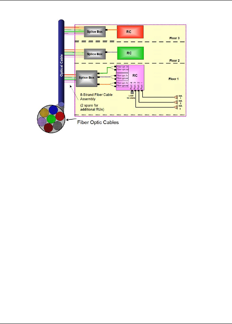
• Fiber optic cable - bundled fibers are terminated into the Base Units in the main
communication room. The fibers are then routed to each coverage locations where
individual fibers terminate into splice boxes. The splice box couples the installed fiber
into the remote units. Enough spare fibers should be installed to take into account
future expansion of the system.
For example, for three remote units, six fibers are required. However, to allow for future
expansion, it is recommended to install additional optic fibers to be connected to additional
RUs.
Continued on the following page...
Appendix C: Site Preparation
MobileAccessHX Installation and Configuration Guide 42
The following figure illustrates fiber optic routing to Remote Cabinets.
Figure 4-1. Illustration of Fiber Optic Routing
• For remote power supply configuration - cable bundles are routed from the main
communication room and individual wire pairs are terminated into the power feed of
individual units.
By providing power from a single distribution point, maintenance can be reduced and UPS
backup can be easily provided. The maximum distance from the source to the termination
spot is 1000 feet using 18 gauge wires.
In many locations local codes do not require power to be run through conduit if 100 watts or
less is used. Please consult the regulations in your local jurisdiction prior to deploying
remote power. When power cables require distances greater than 1000 feet 14 or 16 gauge
wire may be used.
• On each floor - the antennas are connected to the Remote Cabinet or MA2000-Lite system
using coax cables.