Corning Optical Communication HXP19S80A17L70 Mid-power remote unit-HX5 User Manual DAS System
Corning Optical Communication Wireless Mid-power remote unit-HX5 DAS System
Contents
- 1. Users Manual
- 2. User Manual
User Manual

HX Mid-Power Distributed
Antenna System (DAS)
User Manual
Corning Optical Communications User Manual I CMA-066-AEN I Page 2
Draft
Warranties
Hardware
Corning Optical Communications Wireless, Inc. (“Corning) warrants to the original purchaser (“Customer”) that for the
duration of the warranty period, one (1) year, commencing on the date of shipment of the Hardware, unless otherwise agreed
in writing by Corning
(the “Hardware Warranty Period”), the Hardware furnished by Corning shall be free in all material respects from defects in
material and workmanship, and shall conform to the applicable portions of the Specifications, as defined below (the
“Hardware Warranty”). If notified by Customer of any such defects in material or workmanship or nonconformity with
applicable portions of the Specifications within the Hardware Warranty Period, Corning Optical Communications shall
promptly, at its own election and expense, repair or replace any such Hardware proven to be defective under the terms of this
Hardware Warranty. Such repair or replacement shall be Customer’s sole remedy and Corning Optical Communications’ sole
obligation in the event this Hardware Warranty is invoked. If any components comprising a part of the Hardware are replaced
or repaired during the Hardware Warranty Period, the Hardware Warranty Period for such repaired or replaced components
shall extend to the longer of (i) the balance of the Hardware Warranty Period or (ii) three (3) months from the date of repair or
replacement. For purposes of this Warranty, “Specifications” shall mean the specifications and performance standards of the
Products as set forth in documents published by Corning Optical Communications and delivered to Customer which contain
technical specifications or performance standards for the Products.
If Customer invokes this Hardware Warranty, it shall notify Corning promptly of the claimed defect. Customer will allow
Corning to inspect the Hardware at Customer’s location, or to return the Hardware to Corning’s closest repair facility. For
Hardware returned to Corning’s repair facility, Customer shall be responsible for payment of all transportation and freight
costs (including insurance) to Corning’ repair facility, and Corning shall be responsible for all transportation and freight costs
(including insurance) incurred in connection with the shipment of such Hardware to other repair facilities of Corning and/or its
return to Customer.
Notwithstanding the foregoing, in no event will Corning be liable for damage to Products resulting from improper handling
during or after shipment, misuse, neglect, improper installation, operation or repair (other than by authorized Corning
personnel), alteration, accident, or for any other cause not attributable to defects in materials or workmanship on the part of
Corning. Corning shall not reimburse or make any allowance to Customer for any labor charges incurred by Customer for
replacement or repair of any goods unless such charges are authorized in advance in writing by Corning.
Software Warranty
Corning warrants to the original purchaser (“Customer”) that for the duration of the warranty period, one (1) year,
commencing on the date of shipment of the Software, unless otherwise agreed in writing by Corning (the “Software Warranty
Period”), the Software shall conform with, and perform the functions set forth in the Specifications, and shall be free from
defects in material or workmanship (the “Software Warranty”). In the event the Software is proven to be defective under the
terms of this Software Warranty, Corning shall correct such defects or failure and ensure that the Software conforms with,
and performs the functions set forth in, the Specifications. Customer will allow Corning to inspect the Software at Customer’s
location or to return it to Corning’s closest repair facility.
Notwithstanding the foregoing, Corning shall have no obligation under the Software Warranty if the Software is modified or
used with hardware or software not supplied or approved by Corning or if the Software is subject to abuse, improper
installation or application, accident, electrical or environmental over-stress, negligence in use, storage, transportation or
handling.
Third-party software distributed with the Software may carry certain warranties which, to the maximum extent allowed by law,
Corning hereby assigns, transfers and otherwise conveys to Customer, provided, however, that Corning itself provides no
warranty of any kind, express, implied, statutory or otherwise, for any third-party software provided hereunder.
Corning does not warrant any hardware, software or services not provided by Corning.
Corning Optical Communications User Manual I CMA-066-AEN I Page 3
Draft
THIS WARRANTY IS THE ONLY WARRANTY MADE BY CORNING AND IS IN LIEU OF ALL OTHER WARRANTIES,
EXPRESS OR IMPLIED INCLUDING, BUT NOT LIMITED TO, THE IMPLIED WARRANTIES OF MERCHANTABILITY AND
FITNESS FOR A PARTICULAR PURPOSE. CORNING SHALL NOT BE LIABLE FOR ANY OTHER DAMAGE INCLUDING,
BUT NOT LIMITED TO, INDIRECT, SPECIAL OR CONSEQUENTIAL DAMAGES ARISING OUT OF OR IN CONNECTION
WITH FURNISHING OF GOODS, PARTS AND SERVICE HEREUNDER, OR THE PERFORMANCE, USE OF, OR
INABILITY TO USE THE GOODS, PARTS AND SERVICE. CORNING SALES AGENTS OR REPRESENTATIVES ARE
NOT AUTHORIZED TO MAKE COMMITMENTS ON WARRANTY RETURNS.
Returns
In the event that it is necessary to return any product against above warranty, the following procedure shall be followed:
1. Return authorization is to be received from Corning prior to returning any unit. Advise Corning of the model, Serial
number, and discrepancy. The unit may then be forwarded to Corning Optical Communications, transportation prepaid.
Devices returned collect or without authorization may not be accepted.
2. Prior to repair, Corning will advise the customer of our test results and any charges for repairing customer-caused
problems or out-of-warranty conditions etc.
3. Repaired products are warranted for the balance of the original warranty period, or at least 90 days from date of shipment.
Limitations of Liabilities
Corning’s liability on any claim, of any kind, including negligence for any loss or damage arising from, connected with, or
resulting from the purchase order, contract, quotation, or from the performance or breach thereof, or from the design,
manufacture, sale, delivery, installation, inspection, operation or use of any equipment covered by or furnished under this
contact, shall in no case exceed the purchase price of the device which gives rise to the claim.
Except as expressly provided herein, Corning makes no warranty, expressed or implied, with respect to any goods, parts and
services provided in connection with this agreement including, but not limited to, the implied warranties of merchantability and
fitness for a particular purpose. Corning shall not be liable for any other damage including, but not limited to, indirect, special
or consequential damages arising out of or in connection with furnishing of goods, parts and service hereunder, or the
performance, use of, or inability to use the goods, parts and service.
Reporting Defects
The units were inspected before shipment and found to be free of mechanical and electrical defects. Examine the units for
any damage that may have been caused in transit. If damage is discovered, file a claim with the freight carrier immediately.
Notify Corning as soon as possible in writing.
Note: Keep all packing material until you have completed the inspection.
Corning Optical Communications User Manual I CMA-066-AEN I Page 4
Draft
Warnings and Admonishments
There may be situations, particularly for workplace environments near high-powered RF sources, where recommended limits
for safe exposure of human beings to RF energy could be exceeded. In such cases, restrictive measures or actions may be
necessary to ensure the safe use of RF energy.
The equipment has been designed and constructed to prevent, as far as reasonably, practicable danger. Any work activity on
or near equipment involving installation, operation or maintenance must be, as far as reasonably, free from danger.
Where there is a risk of damage to electrical systems involving adverse weather, extreme temperatures, wet, corrosive or
dirty conditions, flammable or explosive atmospheres, the system must be suitably installed to prevent danger.
Equipment provided for the purpose of protecting individuals from electrical risk must be suitable for the purpose and properly
maintained and used. This covers a range of activities including lifting, lowering, pushing, pulling, carrying, moving, holding or
restraining an object, animal or person from the equipment. It also covers activities that require the use of force or effort, such
as pulling a lever, or operating power tools.
Where some of the abovementioned activities are required, the equipment must be handled with care to avoid being
damaged.
Observe standard precautions for handling ESD-sensitive devices. Assume that all solid-state electronic devices are ESD-
sensitive. Ensure the use of a grounded wrist strap or equivalent while working with ESD-sensitive devices. Transport, store,
and handle ESD-sensitive devices in static-safe environments.
RF Safety
WARNING! To comply with FCC RF exposure compliance requirements, each individual antenna used for this transmitter
must be installed to provide a separation distance greater than 170 cm or more from all persons during normal operation and
must not be co-located with any other antenna for meeting RF exposure requirements.
The design of the antenna installation needs to be implemented in such a way so as to ensure RF radiation safety levels and
non-environmental pollution during operation.
WARNING! Antenna gain should not exceed 12.5 dBi.
WARNING! The design of the antenna installation needs to be implemented in such a way so as to ensure RF radiation
safety levels and non-environmental pollution during operation.
Compliance with RF safety requirements:
• Corning products have no inherent significant RF radiation.
• The RF level on the downlink is very low at the downlink ports. Therefore, there is no dangerous RF radiation when the
antenna is not connected.
Power requirements for DC Inputs
WARNING! Only use a special DC supply cable with four connectors
WARNING! Always keep DC IN connectors connected during the product operation
WARNING! Disconnect all power from the equipment by means of an external circuit breaker before connecting or
disconnecting the DC IN connectors.

Corning Optical Communications User Manual I CMA-066-AEN I Page 5
Draft
Laser Safety
Fiber optic ports of the HX system emit invisible laser radiation at the 1310/1550 nm wavelength window.
The laser apertures /outputs are the green SC/APC Bulkhead adapters located on the front panel of the equipment.
The product is Class 1/Hazard level 1
External optical power is less than 10 mW, Internal optical power is less than 500 mW.
To avoid eye injury never look directly into the optical ports, patchcords or optical cables. Do not stare into beam or view
directly with optical instruments. Always assume that optical outputs are on.
Only technicians familiar with fiber optic safety practices and procedures should perform optical fiber connections and
disconnections of HX devices and the associated cables.
HX has been tested and certified as a Class 1 Laser product to IEC/EN 60825-1 (2007). It also meets the requirements for a
Hazard Level 1 laser product to IEC/EN 60825-2: 2004 to the same degree.
HX complies with 21 CFR 1040.10 and 1040.11 except for deviations pursuant to Laser Notice NO. 50 (2007).
Care of Fiber Optic Connectors
Do not remove the protective covers on the fiber optic connectors until a connection is ready to be made. Do not leave
connectors uncovered when not connected.
The tip of the fiber optic connector should not come into contact with any object or dust.
Regulatory Compliance Information
WARNINGS!
• This is NOT a CONSUMER device. It is designed for installation by FCC LICENCEES and QUALIFIED INSTALLERS.
You MUST have an FCC LICENSE or express consent of an FCC Licensee to operate this device. Unauthorized use
may result in significant forfeiture penalties, including penalties in excess of $100,000 for each continuing violation.
• ANTENNAS: Use only authorized and approved antennas, cables and/or coupling devices! The use of unapproved
antennas, cables or coupling devices could cause damage and may be of violation of FCC regulations. The use of
unapproved antennas, cables and/or coupling devices is illegal under FCC regulations and may subject the user to
fines.

Corning Optical Communications User Manual I CMA-066-AEN I Page 6
Draft
Standards and Certifications
Corning Optical Communications products have met the approvals of the following certifying organizations:
Company Certification
ISO 9001: 2000 and ISO 13485: 2003
Product Certification
US
Radio Equipment and Systems
• FCC 47 CFR part 22 – for CELL Frequency Band
• FCC 47 CFR part 24 – for PCS Frequency Band
• FCC 47 CFR part 27 – for LTE and AWS Frequency Bands
EMC
• FCC CFR part 15 Subpart B
Note: This equipment has been tested and found to comply with the limits for a Class A digital device, pursuant to
Part 15 of the FCC Rules. These limits are designed to provide reasonable protection against harmful interference
in a residential installation. This equipment generates, uses and can radiate radio frequency energy and, if not
installed and used in accordance with the instructions, may cause harmful interference to radio or television
reception, which can be determined by turning the equipment off and on, the user is encouraged to try to correct
the interference by one or more of the following measures:
- Reorient or relocate the receiving antenna.
- Increase the separation between the equipment and receiver.
-Connect the equipment into an outlet on a circuit different from that to which the receiver is connected.
-Consult the dealer or an experienced radio/TV technician for help.
Warning!
Changes or modifications to this equipment not expressly approved by Corning Mobile Access could void the
user’s authority to operate the equipment.
Europe
Radio Equipment and Systems
• EN 301502 – for GSM/EGSM Frequency Bands
• EN 300609 – for DCS Frequency Bands
• EN 301908 – for UMTS Frequency Band
EMC
• EN 301 489
Licensee Contact Information
Industrial Boosters may only be used by FCC licensees or those given express (individualized) consent of license. Corning
certifies all of the VARs listed as licensed installers for Corning. For the list of licensed VARs, please contact the Corning
Tech Support Hotline: (US) 410-553-2086 or 800-787-1266.
Corning Optical Communications User Manual I CMA-066-AEN I Page 7
Draft
About this Guide
This Installation Guide describes how to perform the physical installation of the HX indoor and outdoor units (not including
HX2600). The installation procedures of other units (e.g. RIU, OCH-HX, SC-450) relevant to the system are detailed in their
user manuals (see Additional Relevant Documentation).
Additional Relevant Documents
The following documents are required if the corresponding units are included in your system.
Document Name
Corning Mid-Power HX WCS DAS user manual
Corning Mid-Power HX 2.5 GHz TDD user manual
RIU Product Line User Manual; RIU-12 user manual
FT350 User Manual (includes OCH information)
System Controller (SC-450) user manual
MA Software Version Update Tool
List of Acronyms
Acronym
Description
BDA
Bi-Directional Amplifier
BTS
Base Transceiver Station
BU
Base Unit
DL
Downlink
HX
High Power Transmission
OCH
Optical Central Hub
RU
Remote Unit
RIU
Radio Interface Unit
SC-450
System Controller
UL
Uplink
Corning Optical Communications User Manual I CMA-066-AEN I Page 8
Table of Contents
1 Introduction ...................................................................................................................... 10
1.1 Features and Capabilities ................................................................................................................... 11
1.2 System Architecture ............................................................................................................................ 12
1.2.1 HX Neutral Host Solution .......................................................................................................... 14
1.3 Application Topologies ........................................................................................................................ 15
1.4 System Monitoring and Management ................................................................................................. 16
1.5 HX Unit Interfaces ............................................................................................................................... 17
1.5.1 HX Indoor Interfaces ................................................................................................................. 17
1.5.1.1 HX Indoor SISO Internal and Front Panel Interfaces .................................................. 17
1.5.1.2 HX Indoor MIMO Internal and Front Interfaces ........................................................... 19
1.5.2 HX Outdoor Unit Interfaces ....................................................................................................... 21
2 Installation Guidelines ..................................................................................................... 22
2.1 Site Considerations ............................................................................................................................. 22
2.2 Environmental ..................................................................................................................................... 22
2.3 Installation Requirements .................................................................................................................... 22
2.4 Fiber Optic Requirements ................................................................................................................... 23
2.4.1 Authorized Optic Cables ........................................................................................................... 23
2.4.2 Fiber Optic Rules ...................................................................................................................... 24
2.5 RF Coaxial Cable Guidelines .............................................................................................................. 24
2.5.1 General Cable Installation Procedures ..................................................................................... 24
2.5.2 RF Rules ................................................................................................................................... 25
2.5.3 Coax Cable Lengths and Losses .............................................................................................. 25
2.5.4 Cable Routing ........................................................................................................................... 26
2.6 Antenna Specifications and Guidelines .............................................................................................. 26
2.6.1 Authorized Antennas and Couplers .......................................................................................... 26
2.6.2 General Antenna Installation Guidelines .................................................................................. 26
2.7 Grounding Requirement ...................................................................................................................... 26
2.8 Manual Handling ................................................................................................................................. 26
3 HX Indoor Physical Installation ....................................................................................... 27
3.1 Unpacking and Inspection ................................................................................................................... 27
3.2 Mounting .............................................................................................................................................. 28
3.2.1 General Instructions .................................................................................................................. 28
3.2.2 Rack Mount Installation ............................................................................................................. 28
3.2.3 Wall-Mount Installation .............................................................................................................. 30
3.2.3.1 Required/Recommended Tools and Materials for Wall Mount Installation ................. 30
3.2.3.2 Mounting HX on Wall ................................................................................................... 30
3.3 Connections ........................................................................................................................................ 33
3.3.1 RF and Fiber Connections ........................................................................................................ 33
3.3.2 Ground Connection ................................................................................................................... 34
3.3.3 Power Connections ................................................................................................................... 34
3.3.3.1 AC Models ................................................................................................................... 34
Corning Optical Communications User Manual I CMA-066-AEN I Page 9
3.3.3.2 DC Models ................................................................................................................... 35
3.3.4 Routing Fiber and Power Cables .............................................................................................. 36
3.4 Verify Normal Operation ...................................................................................................................... 37
4 HX Outdoor Physical Installation .................................................................................... 39
4.1 General Information ............................................................................................................................ 39
4.2 Unpacking and Inspection ................................................................................................................... 39
4.3 HX Outdoor Dimensions ..................................................................................................................... 40
4.4 Required/Recommended Tools and Materials for Wall Mount Installation ......................................... 41
4.5 Mounting .............................................................................................................................................. 42
4.5.1 Wall Mount Installation .............................................................................................................. 42
4.5.2 Pole Mount Installation .............................................................................................................. 45
4.6 Connections ........................................................................................................................................ 48
4.6.1 RF and Fiber Connections ........................................................................................................ 48
4.6.2 Ground Connection ................................................................................................................... 49
4.6.3 Power Connections ................................................................................................................... 50
4.6.3.1 AC Power Input Model Connections ............................................................................ 50
4.6.3.2 DC Power Input Model Connections............................................................................ 51
4.7 Verify Normal Operation ...................................................................................................................... 52
5 Appendix A: System Specifications ............................................................................... 53
5.1 RF Parameters .................................................................................................................................... 53
Supported Services ............................................................................................................................. 53
RF Parameters per Low-Band Service ............................................................................................... 53
RF Parameters per High-Band Service............................................................................................... 54
Coupling Specifications* ..................................................................................................................... 54
5.2 Optical Specifications .......................................................................................................................... 55
5.3 Physical Specifications ........................................................................................................................ 55
5.3.1 Indoor Remote Unit ................................................................................................................... 55
5.3.2 Outdoor Remote Unit ................................................................................................................ 56
5.4 Environmental Specifications .............................................................................................................. 56
5.5 Standards and Certifications ............................................................................................................... 56
6 Appendix B: Ordering Information .................................................................................. 58
6.1 HX Indoor Remote Units (SISO and MIMO) ....................................................................................... 58
6.2 HX Remote Outdoor Units (SISO services) ........................................................................................ 59
6.3 Accessory Kits ..................................................................................................................................... 60
6.4 Optical Central Hub (OCH) - HX International products ..................................................................... 60
6.5 Corning OptiTap™ Cables .................................................................................................................. 60
7 Appendix C: HX Outdoor Non-Standard Connector Descriptions ................................ 61
8 Appendix D: Power Cable Specifications ....................................................................... 62
8.1 AC Power Cable Specifications .......................................................................................................... 62
8.2 DC Power Cable Specifications .......................................................................................................... 62
Corning Optical Communications User Manual I CMA-066-AEN I Page 10
1 Introduction
HX is a mid-power, remote solution for the MA1000 and MA2000 distributed antenna systems (DAS). It is a fiber fed,
compact and scalable multi-service platform designed to complement the MA1000 and MA2000 while providing complete
RF open space coverage for large-scale public venues such as campuses, stadiums, convention centers, hotels, airports
and train stations. The solution can be deployed in new sites or alongside existing lower power MA1000 and MA2000
systems, sharing a common headend and element management system (SC-450).
HX supports multiple wireless technologies and operator services over a single broadband infrastructure. Using low-loss
fiber optic cabling, remote units can cover distances of up to 2 km from the BTS signal sources at the headend.
Alongside other HX products (e.g. HX WCS, HX 2500 MHz TDD) and MA1000 and MA2000 deployments, HX provides a
comprehensive indoor and outdoor coverage solution for varying site requirements, supporting everything from high-rise
buildings and campus topologies to stadiums and airports.
In addition, the HX remote can be combined with an MA2000 lower power remote or HX remote supporting the HX 800
MHz ESMR band to create an HX Neutral Host Solution. The NH solution addresses the need for complete multiservice
coverage while meeting RSSI requirements for different cellular technologies.
Note: Refer to the HX Neutral Host Solution Application Note for details on combining HX Quad-Band solution with Sprint’s
800 MHz Band (CMA-238-AEN).
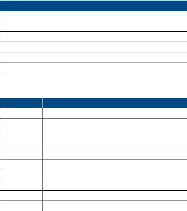
HX Indoor Model (LT) and HX Outdoor Model (RT) Figure 1-1
Corning Optical Communications User Manual I CMA-066-AEN I Page 11
1.1 Features and Capabilities
• Multi-Service Platform: Accommodates GSM, UMTS, HSPA, LTE, EDGE, EV-DO, AWS3, and more. Provides MIMO
configuration for LTE700, AWS3, and UMTS band.
• Cost-Effective High Power: Optimizes and reduces the number of antennas required to cover open areas by offering up
to 33 dBm (2 W) composite power per frequency band.
• Indoor Models: Support either SISO or MIMO (excluding HX-5 units) service in a single compact enclosure.
• Outdoor Models: Outdoor enclosures are compliant to NEBS OSP Class 4 standards.
• Operator-Grade Operation: Advanced signal handling and management ensures carrier-grade performance in multi-
operator deployments.
• Design and Deployment Flexibility: Remote unit supports SM fiber connections, and is available in AC or DC power
supply options. Antenna splitting schemes are possible due to the higher power output capability.
• Backwards Compatible: Connects to an existing MA1000/MA2000 deployment and shares a common headend and
element management system (EMS) in a single deployment.
Corning Optical Communications User Manual I CMA-066-AEN I Page 12
1.2 System Architecture
HX mid-power remote unit compliments the MA1000 or MA2000 system, providing a complete solution consisting of HX
remote units at the remote locations and headend elements that are shared with any other MA1000 or MA2000 system
remotes that are either installed or being installed at the site. HX4/HX5 units can be optically daisy chained to other HX
units supporting different bands (e.g. WCS and 2500 MHz TDD) for further band coverage needs.
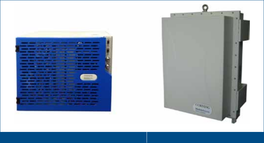
In the downlink, at the headend, the BTS or BDA signal is conditioned by the RIU, ensuring a constant RF level. The
conditioned signal is then converted by an optical converter unit (i.e. base unit) to an optical signal to transport over single-
mode fiber to the HX remote units, which are located at the remote locations. In the uplink, the process is reversed.
The system controller (SC-450) enables local and remote management, as well as controls all MA1000, MA2000 and HX
elements from a single, centralized location.
The HX remote unit consists of a compact enclosure that houses the RF module, power elements and the required
interfaces. The RF module supports various configurations of three (International models), four and five bands.
Note: HX-5 units are SISO only.
All mobile services are combined and distributed through a single antenna port over antennas installed at the remote
locations.
Example of SISO Architecture with HX4 Indoor, HX WCS, and HX5 Outdoor Figure 1-2
Corning Optical Communications User Manual I CMA-066-AEN I Page 13
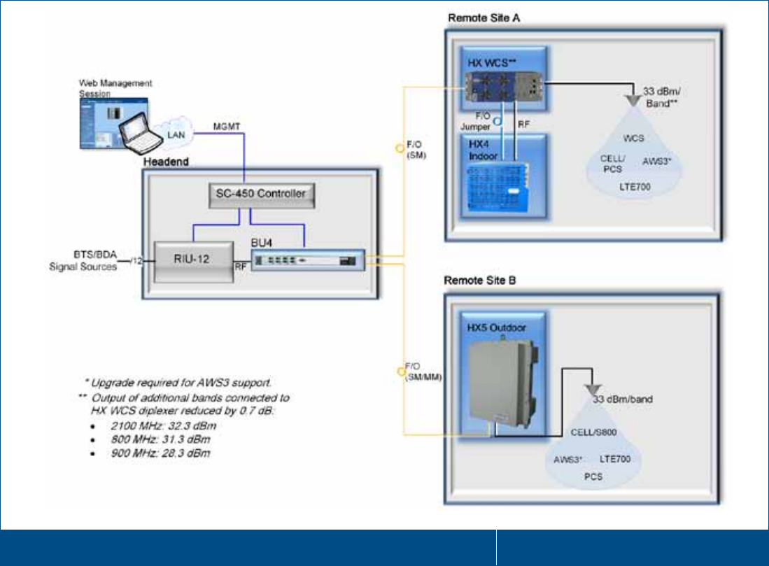
Example of Indoor MIMO Architecture with HX Quad-Band Figure 1-3
Corning Optical Communications User Manual I CMA-066-AEN I Page 14
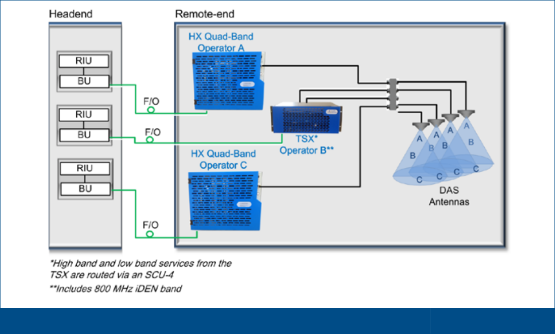
1.2.1 HX Neutral Host Solution
Corning HX Neutral Host solution addresses the need for a high-output multi-operator distributed antenna solution (DAS)
that provides complete multiservice coverage and meets RSSI requirements for different cellular technologies. The HX
neutral host solution provides a complete suite of solutions to combine 850 CELL, 1900 PCS, 700 LTE and 2100 AWS
services of the HX product with 800 MHz ESMR band.
HX neutral host extends the multiband support of the HX to 800 MHz ESMR band by providing solutions to combine the
corresponding Corning MA2K system, supporting the 800 MHz ESMR band or HX supporting the 800 MHz ESMR band to
create the HX NH solution.
Note: The 800 MHz ESMR band is a low frequency band so that it also meets the RSSI requirements despite lower output
power.
Dedicated HX NH SISO Scenario Configuration with HX Quad SISO and MA2000 TSX Units Figure 1-4
Corning Optical Communications User Manual I CMA-066-AEN I Page 15
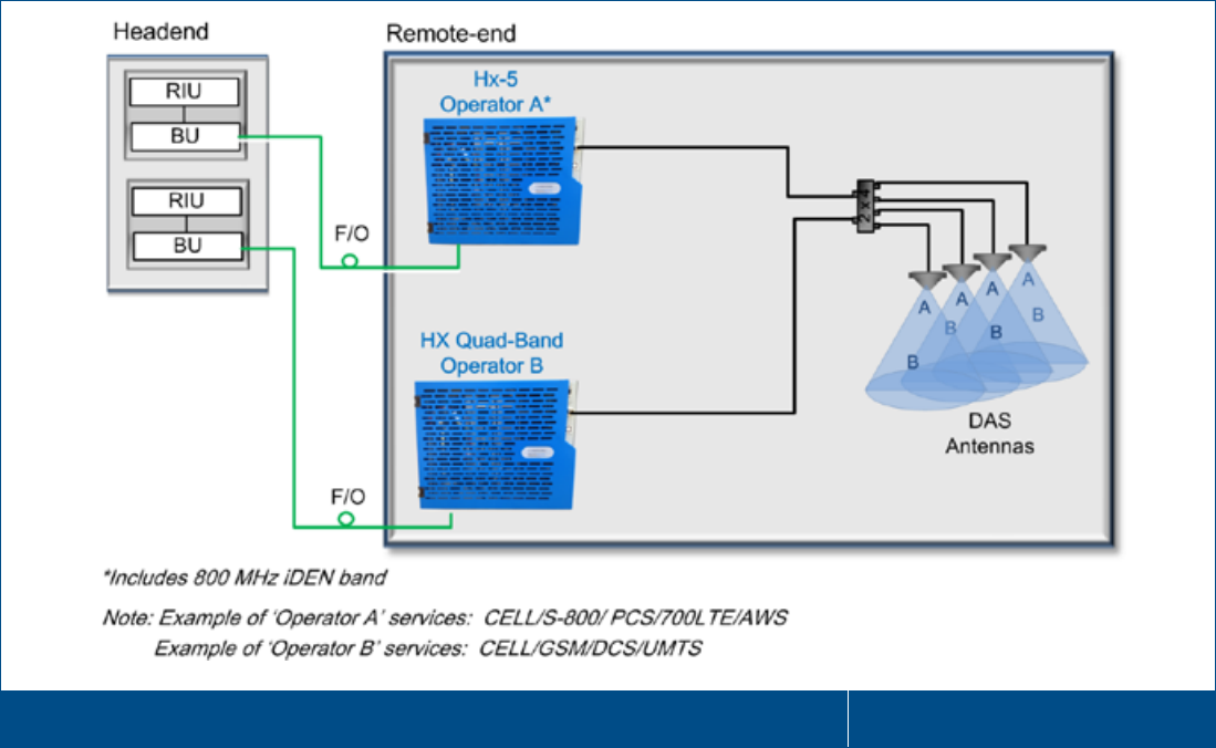
Dedicated HX NH SISO Scenario Configuration with HX Quad and HX-5 SISO Units Figure 1-5
1.3 Application Topologies
HX can be installed in various site topologies. The setup procedure varies accordingly:
• High-power coverage via a single antenna - used for open area, stadium, parking lots, etc.
• RF signal is distributed over several antennas via splitters
• Special coverage requirements using directional antennas
Corning Optical Communications User Manual I CMA-066-AEN I Page 16
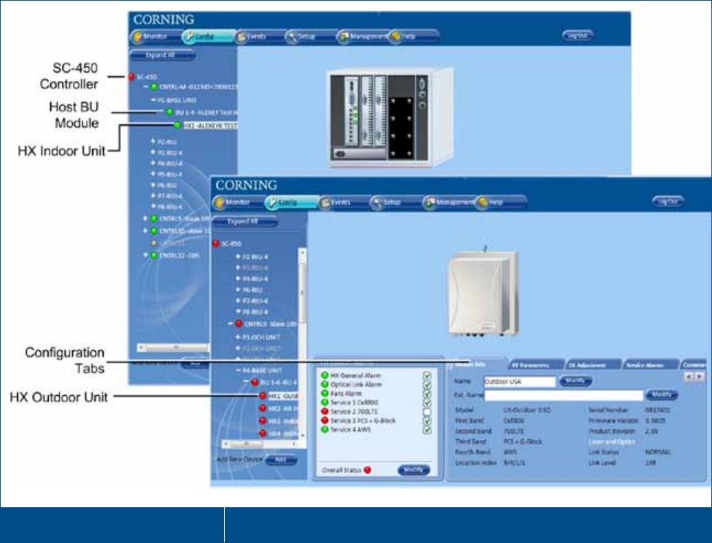
1.4 System Monitoring and Management
The HX Remote Unit is centrally managed via the SC-450 Controller. Note that HX is not connected directly to the
controller. It is connected to the optical converter (i.e. BU or OCH-HX), connected to the controller. Thus, the controller
monitors views and manages the HX via the optical converter module to which the HX is connected.
The following shows the Config(uration) tabs of the selected HX unit. Refer to the SC-450 Controller User Manual for
information on how to configure and manage the HX (Indoor/Outdoor) unit.
Example of HX Configuration Tab Figure 1-6
Corning Optical Communications User Manual I CMA-066-AEN I Page 17
1.5 HX Unit Interfaces
The HX antenna port (two for MIMO) is located externally. All other interfaces such as F/O connections, power connections,
etc. are located inside the cabinet and are accessed by opening the cabinet door.
1.5.1 HX Indoor Interfaces
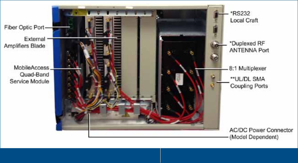
1.5.1.1 HX Indoor SISO Internal and Front Panel Interfaces
The HX Indoor ANTENNA port (two for MIMO models) is located externally. All other interfaces such as F/O connections,
power connections, etc. are located inside the cabinet and are accessed by opening the cabinet door.
The HX Model Components:
• Quad-band Service Module – Connects to the optical converter unit (BU/OCH) using a single fiber pair and supports up
to four services
• External Amplifier Blade – Two External Amplifiers are mounted on each of the two blades and provide the additional
amplification on the DL signals coming from the Quad-band Service Module to the Multiplexer
• 8:1 Multiplexer – Combines UL and DL signals of the four bands, while providing the proper filtering, into a single
duplexed antenna port
• Power Supply – Local AC or Remote DC power feed (model dependent)
• Duplexed Antenna Port *– Interface to RF antennas
• **Coupler Ports – Coupler ports used for enabling the user/field engineer to measure the signals at the remote without
disconnecting the antenna cable and affecting services on the main stream.
* Upgradeable SISO models include MIMO1 and MIMO2 duplex RF ports and craft ports, however only the MIMO1 ports
are applicable.
** Model dependant – refer to Ordering Information in Appendix B.
Example of Indoor HX Remote Unit Interfaces – Front View Figure 1-7
Corning Optical Communications User Manual I CMA-066-AEN I Page 18
Table 1-1 and Table 1-2 provide descriptions of the HX Indoor connectors and LEDs.
Connector
Description
F/O SC/APC fiber-optic connector SM fibers
Antenna N-Type female 50Ω duplexed connector for RF antenna
AC PWR 100/240 VAC; 50/60 Hz; 8A Slow Blow Fuse
DC 18 pin power connector for 25-48V DC power feeds
RS-232 Local craft connector
Table 1-1. Connector Descriptions
LED
Description
Color
Status
Power Device is powered Green Steady On
Power not supplied to the unit
Green
Off
Comm When connected and discovered by an
OPTM (BU)
Green Blink per communication
attempt
When device is powered on but no
external communication is received
Green
Steady Slow Blink
Link
No Optical link is present
Green
Off
Low optical link level from OPTM
Green
Blink
Normal optical link level from OPTM
Green
Steady On
Table 1-2. LED Descriptions
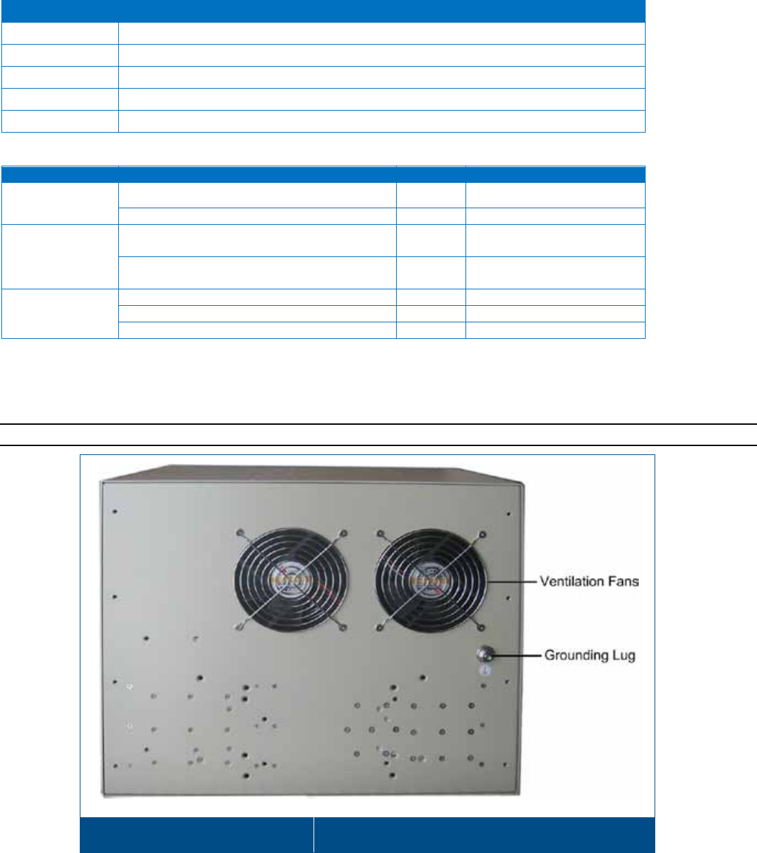
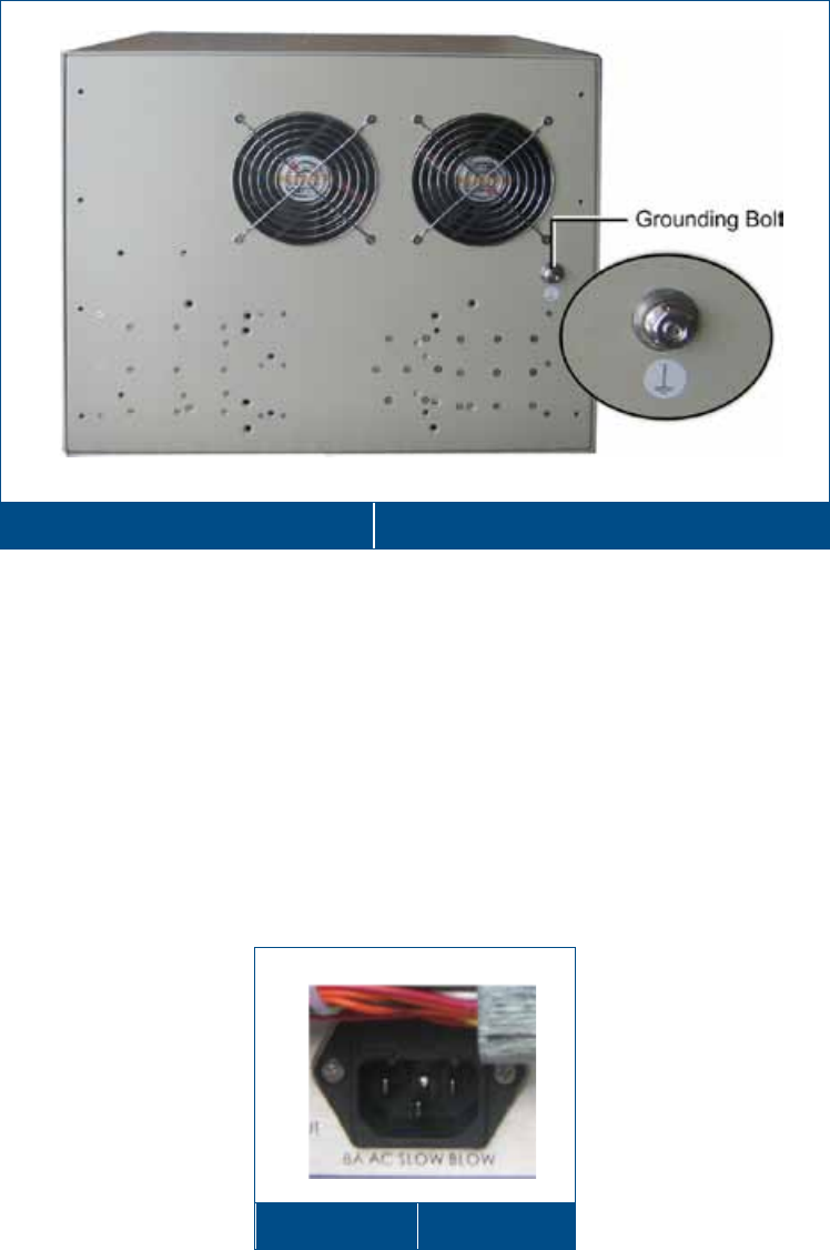
The HX Indoor rear panel includes the grounding lug and ventilation fans.
Note: The rear interfaces are the same for both HX Indoor SISO and MIMO cabinets.
Indoor HX Remote Unit - Rear View Figure 1-8
Corning Optical Communications User Manual I CMA-066-AEN I Page 19
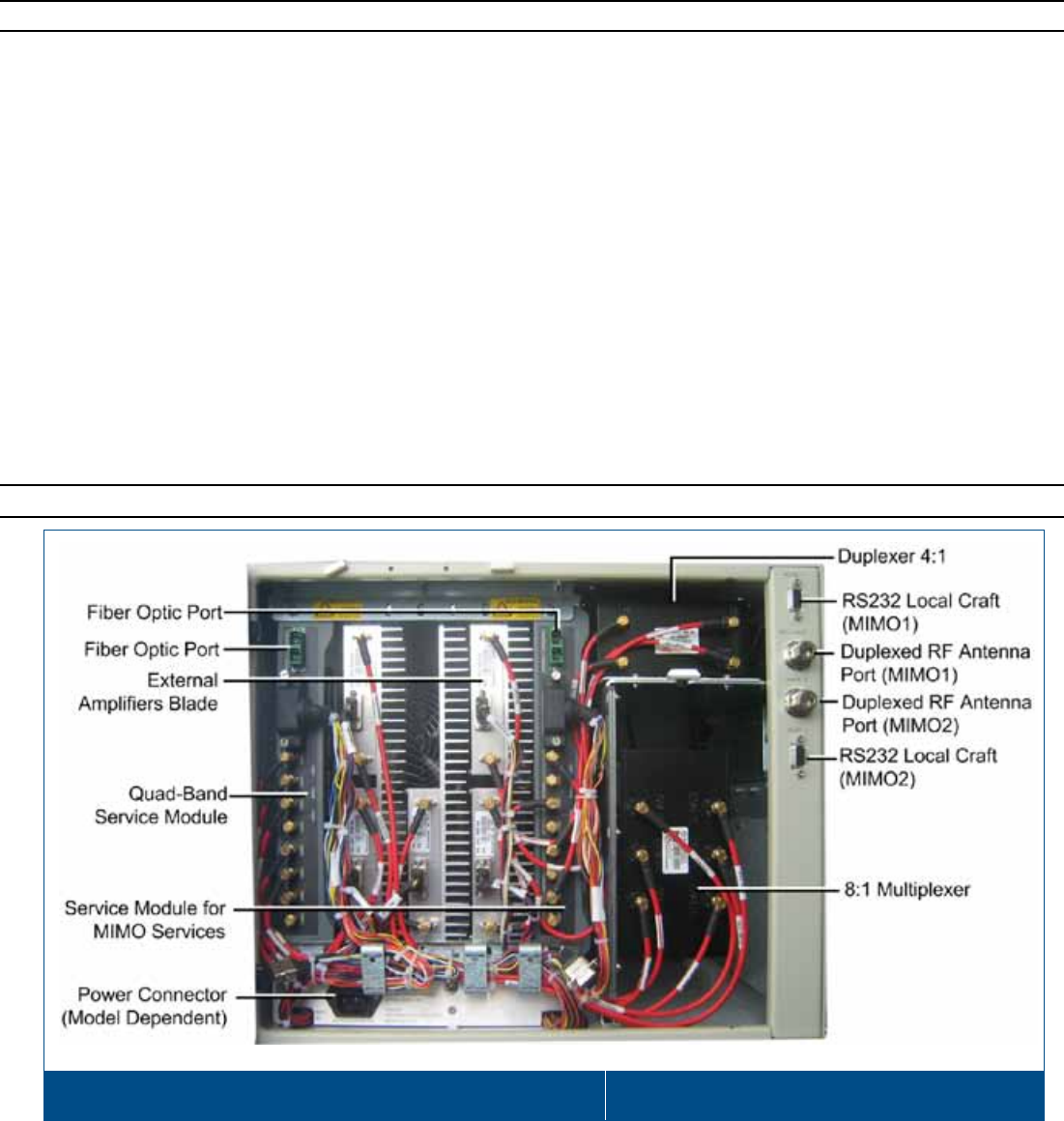
1.5.1.2 HX Indoor MIMO Internal and Front Interfaces
Note: HX-5 units include SISO models only.
The two HX Indoor antenna ports are located externally. All other interfaces such as F/O connections, power connections,
etc. are located inside the cabinet and are accessed by opening the cabinet door.
The HX Indoor MIMO model includes the following main components:
• RF Modules:
• Quad-band Service Module – connects to the Base Unit using a single fiber pair and supports up to four services
(SISO/MIMO1)
• Additional RF module providing support for two MIMO2 services – connects to the Base Unit using a single fiber pair
• External Amplifier Blade – Two External Amplifiers are mounted on each of the 2 blades and provide the additional
amplification on the DL signals coming from the Quad-band Service Module top the Multiplexer
• 8:1 Multiplexer – combines UL and DL signals of the four bands, while providing the proper filtering, into a duplexed
antenna port
• Duplexer - combines UL and DL signals of the Stream 2 MIMO bands , while providing the proper filtering, into the
MIMO2 duplexed antenna port
• Power supply – local AC or Remote DC power feed (model dependent)
• Duplexed Antenna Ports (MIMO1 and MIMO2) – interface to RF antennas
Note: Detailed descriptions of the components and LEDs are provided Table
1-3 and Table
1-4.
Example of HX Indoor MIMO Remote Unit Internal View (Front) Figure 1-9
Corning Optical Communications User Manual I CMA-066-AEN I Page 20
Table 1-3 and Table 1-4 provide descriptions of the HX indoor type connectors and LEDs.
Connector
Description
F/O SC/APC fiber-optic connector for either SM fibers (1 for each RF service module)
Antenna N-Type female 50Ω duplexed connector for RF antenna (MIMO1 and MIMO2)
AC PWR 100/240 VAC; 50/60 Hz; 8A Slow Blow Fuse
DC PWR 18 pin power connector for 25-48V DC power feeds
RS-232 Local craft connector
Table 1-3. Connector Descriptions
Name
Description
Color
Status
Power Device is powered Green Steady On
Power not supplied to the unit Green Off
Comm When connected and discovered by an
OPTM (BU) Green Blink per communication
attempt
When device is powered on but no
external communication is received Green Steady Slow Blink
Link No Optical link is present Green Off
Low optical link level from OPTM Green Blink
Normal optical link level from OPTM Green Steady On
Table 1-4. LED Descriptions
Note: LEDs are the same for each RF module.
Corning Optical Communications User Manual I CMA-066-AEN I Page 21
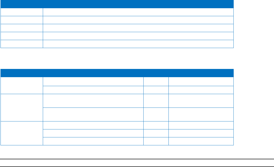
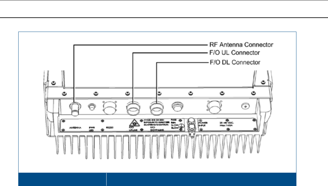
1.5.2 HX Outdoor Unit Interfaces
The HX Outdoor interfaces are located on the underside panel of the unit (connectors face down when unit is mounted).
The unit interfaces include the RF, power and optical link connectors.
The power, RS232 and F/O connectors are special weather resistant connectors. You may either order ready cables from
Corning or refer to the manufacturer Part Numbers for generating the required cables (Appendix C).
HX Outdoor Interfaces Figure 1-10
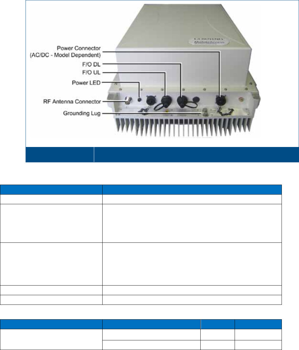
Table 1-5 and Table 1-6 provide a description of the HX Outdoor type connectors and LEDs.
Connector
Description
Antenna N-Type female 50Ω duplexed connector for RF antenna
F/O Uplink and Downlink Corning OptiTap® fiber-optic waterproof connectors for either
SM
IMPORTANT!
OptiTap™ pullout force ranges from a few lbs to
50+ lbs with the dust cap or connector installed. This prevents
damages caused to the DAS unit.
AC or DC PWR (model dependent) Local Power (AC): -20UNEF, plug, 3-pin waterproof, solder for
panel, power connector for 100/240 VAC power feed
Remote DC Power: 1-20UNEF, plug, 8-pin waterproof , solder
for panel, power connector for 25-48 VDC power feed
Max Power Consumption: 340 W
RS-232 One 10-pin RS232 waterproof connector for local craft
Grounding Lug Two hole, standard barrel grounding lug (LCD10-14A-L Panduit)
Table 1-5. HX Outdoor Connector Descriptions
LED
Description
Color
Status
Power Device is powered Green Steady On
Power not supplied to the unit Green Off
Table 1-6: HX Outdoor PWR LED Description
Corning Optical Communications User Manual I CMA-066-AEN I Page 22
2 Installation Guidelines
This chapter describes the installation procedure for the HX Indoor (SISO/MIMO) and Outdoor Remote Units. The
installation procedure differs according to the type of enclosure.
2.1 Site Considerations
• The distance between the HX service antenna and the coverage area should correspond to LOS (Line of Sight)
requirements for maximum coverage area.
• The maximum fiber path loss is 6 dB.
• The system delay of the optical system must be taken into consideration when there are neighboring BTS sites
overlapping in coverage.
2.2 Environmental
Humidity has an adverse effect on the reliability of the equipment. It is recommended to install the equipment in locations
having stable temperature and unrestricted air-flow.
The installation location for the system should be well ventilated. The equipment has been designed to operate at the
temperature range and humidity level as stated in the product specifications with a relative humidity of max. 90% (Indoor
models) and temperatures ranging as follows:
Indoor Models: 0 to 50oC (-4° to 185°F)
Outdoor Models: -30° to +65°C (-22° to 149°F)
2.3 Installation Requirements
• Mounting surface shall be capable of supporting the weight of the equipment.
• In order to avoid electromagnetic interference, a proper mounting location must be selected to minimize interference
from electromagnetic sources such as large electrical equipment.
• Working space available for installation and maintenance for each mounting arrangement. Ensure unrestricted airflow.
• Ensure grounding connector is within reach of the ground wire.
• Ensure a power source is within reach of the power cord and the power source has sufficient capacity.
• Where appropriate, ensure unused RF connectors are terminated.
• Do not locate the equipment near large transformers or motors that may cause electromagnetic interference.
• Reduce signal loss in feeder cable by minimizing the length and number of RF connections.
• Ensure the equipment will be operated within the stated environment (refer to datasheet).
• Where appropriate, confirm available of suitably terminated grade of RF and optical fiber.
• Observe handling of all cables to prevent damage.
Corning Optical Communications User Manual I CMA-066-AEN I Page 23
2.4 Fiber Optic Requirements
2.4.1 Authorized Optic Cables
• Only single mode fiber can be used with HX Indoor/Outdoor products,
• All fiber in a given length of fiber must be of the same core diameter.
For HX Indoor models:
• All Bulkhead adapters must be either Single SC APC (Green) adapters.
• All terminations, cross connections or patches must be direct fusion splice or Corning specified patch cords listed
below.
900 microns pathcord for splicing, 2 Meters, 2xSC/APC
Diamond p/n ENC/1045341 Beige boots, 62.5/125/900 MA# 500001057
Diamond p/n ENC/1045340 Black boots, 50/125/900 MA# 500001058
Zipcord patchcord, 4xSC/APC, 50/125/900/2000/4500 micron
Diamond p/n ENC/1045342 Black/Brown boots, 1 Meter MA# 50000105
Diamond p/n ENC/1045343 Black/Brown boots, 3 Meter MA# 500001060
Zipcord patchcord, 4xSC/APC, 62.5/125/900/2000/4500 micron
Diamond p/n ENC/1045344 Beige/Brown boots, 1 Meter MA# 500001061
Diamond p/n ENC/1045345 Beige/Brown boots, 3 Meter MA# 500001062
For HX Outdoor models :
Use Corning OptiTap™ cables:
Part Number Description
434401EB4R2005M-P OptiTap® to SC/APC 5 meters
434401EB4R2030M-P OptiTap ®to SC/APC 30 meters
434401EB4R2100M-P OptiTap® to SC/APC 100 meters

Corning Optical Communications User Manual I CMA-066-AEN I Page 24
2.4.2 Fiber Optic Rules
ATTENTION!
Please also refer to the Laser Safety section in the document Preface.
• Fiber optic cables require proper handling. Do not stretch, puncture, or crush the fiber cable(s) with staples, heavy
equipment, doors, etc.
• Always maintain the minimum bending radius specified by the cable manufacturer. The minimum bend radius is usually
10 times the cable's outer diameter. In the case of single optical fiber that is not in a cable, the minimum bending radius
to be observed is 30 mm.
• WDM, Wave Division Multiplexing, units require SMF
• For HX Indoor models - use SC APC connectors (green color) 8 deg only.
• For HX Outdoor models – use OptiTap® connector
• Pay special attention while connecting the SC APC connectors - ensure that you hear a “click”, indicating a secure
connection
• Use minimum splicing/connectors to achieve minimum losses on the fibers.
• Use precaution while installing, bending, or connecting fiber optic cables.
• Use an optical power meter and OTDR for checking the fiber optic cables.
• Make sure the environment is clean while connecting/splicing fiber optic cables.
• All fiber optic connectors should be cleaned prior to connecting to the system
• Fiber connector protective caps should be installed on all non-terminated fibers and removed just before they are
terminated.
• Check the fiber optic connections.
• Never look directly into the end of a fiber that may be carrying laser light. Laser light can be invisible and can damage
your eyes.
2.5 RF Coaxial Cable Guidelines
2.5.1 General Cable Installation Procedures
Note: The installer should be familiar with the ANSI/TIA/EIS-568 Cabling Standard guidelines.
Observe the general cable installation procedures that meet with the building codes in your area. The building code requires
that all cabling be installed above ceiling level (where applicable). The length of cable from the risers to each antenna may
need to be concealed above the ceiling.
The cable must be properly supported and maintained straight using velcro cable ties, cable trays and clamps or hangers
every 10 feet (where practical above ceiling level). Where this is not practical, the following should be observed:
• The minimum bending radius of the supplied ½” coax cable should be 7”.
• Cable that is kinked or has a bending radius smaller than 7” must be replaced.
• Cable runs that span less than two floors should be secured to suitably located mechanical structures.
• The cables should be supported only from the building structure.
• All cables shall be weather-resistant type.
• Cable length - determined by the system installation plan. When calculating the cable length, take into account excess
cable slack so as not to limit the insertion paths.
Corning Optical Communications User Manual I CMA-066-AEN I Page 25
2.5.2 RF Rules
• Use coax RG-223, 50 ohm, for RF connections between HX Indoor/Outdoor units and DAS antennas.
• When using the Corning system in an environment in which other indoor coverage systems are installed, it is
recommended (where possible) that the antennas are placed at least two meters apart
• When bending coax cables, verify that the bending radius does not exceed the coax specifications.
• Use wideband antennas supporting a range of 700 MHz to 2600 MHz
• Terminate all unused HX RF ports with a 50 ohm load
• Make sure that the VSWR measured at the coax cable meets the product specification The VSWR must be measured
prior to terminating the HX RF ports in the remote communication rooms.
2.5.3 Coax Cable Lengths and Losses
Use the compatible jumper to connect the coax connector to the external antenna.
Note: The required distance between the antennas (installed in the ceiling) depends on the infrastructure and calculated
path-loss.
Table 2-1. Typical Coax Cable Lengths and Losses
Coax Length
Coax Loss
(900 MHz)
Connector
Loss
Total Loss
30 0.7 1.5 2.2
40 0.9 1.5 2.4
50 1.1 1.5 2.6
60 1.3 1.5 2.8
70 1.5 1.5 3
80 1.7 1.5 3.2
90 1.9 1.5 3.4
100 2.1 1.5 3.6
110 2.3 1.5 3.8
120 2.5 1.5 4
130 2.7 1.5 4.2
140 2.9 1.5 4.4
150 3.1 1.5 4.6
160 3.3 1.5 4.8
170 3.5 1.5 5
180 3.7 1.5 5.2
190 3.9 1.5 5.4
200 4.1 1.5 5.6
Corning Optical Communications User Manual I CMA-066-AEN I Page 26
2.5.4 Cable Routing
Ensure all cables, e.g. power cable, feeder cable, optic fiber, commissioning cable, connecting are properly routed and
secured so that they are not damaged.
2.6 Antenna Specifications and Guidelines
Determine the antenna installation configuration, according to the transmission and coverage requirements and the
installation site conditions.
2.6.1 Authorized Antennas and Couplers
• External antennas - No limitation on any vendor of available external antennas with respect to the following
requirements:
• Omni Directional or Directional
• Supported frequency range: wideband antennas supporting a range of 700 MHz to 2600 MHz
• Gain: up to 12.5 dBi
• Impedance: 50 Ohm
• Types of couplers/splitters – depends on number of splits
• Couplers – Use N-Male to N-Female broadband coupler separately ordered from Corning (P/N AK-1COUPLER-NM-
NF) or the equivalent:
• Broadband frequency: 698 – 2700 MHz
• -40 dB coupling (QMA coupling port)
• Max. VSWR/Return Loss (dB): 1.15:1/-23.0
• Max. Insertion Loss (dB): 0.2
• Impedance: 50 ohms
2.6.2 General Antenna Installation Guidelines
• The wideband antenna should be installed at a convenient location, free of metallic obstruction (can also be installed in
plenum spaces).
• Install the connected antenna at the designated height and tune it roughly toward the Service coverage area.
• Each individual antenna used for this transmitter must be installed to provide the separation distance as specified in the
FCC grant from all persons during normal operation and must not be co-located with any other antenna for meeting RF
exposure requirements
2.7 Grounding Requirement
Verify that the equipment has been well grounded (refer to the grounding lug on the bottom port panel of the HX Outdoor or
on the rear panel of the HX Indoor). This includes antennas and all cables connected to the system. Ensure lightning
protection for the antennas is properly grounded. Also, see sections 3.3.2 (HX Indoor) and 4.6.2 (HX Outdoor).
2.8 Manual Handling
During transportation and installation, take necessary handling precautions to avoid potential physical injury to the
installation personnel and the equipment.
Corning Optical Communications User Manual I CMA-066-AEN I Page 27
3 HX Indoor Physical Installation
This chapter describes the mounting procedure and physical connections for the HX Indoor (SISO/MIMO) Remote Unit.
3.1 Unpacking and Inspection
Unpack and inspect the cartons according to the following procedure
1. Open the shipping carton and carefully unpack each unit from the protective packing material.
2. Verify that all the parts have been received (see Table 3-1).
3. Check for signs of external damage. If there is any damage, call your Corning service representative.
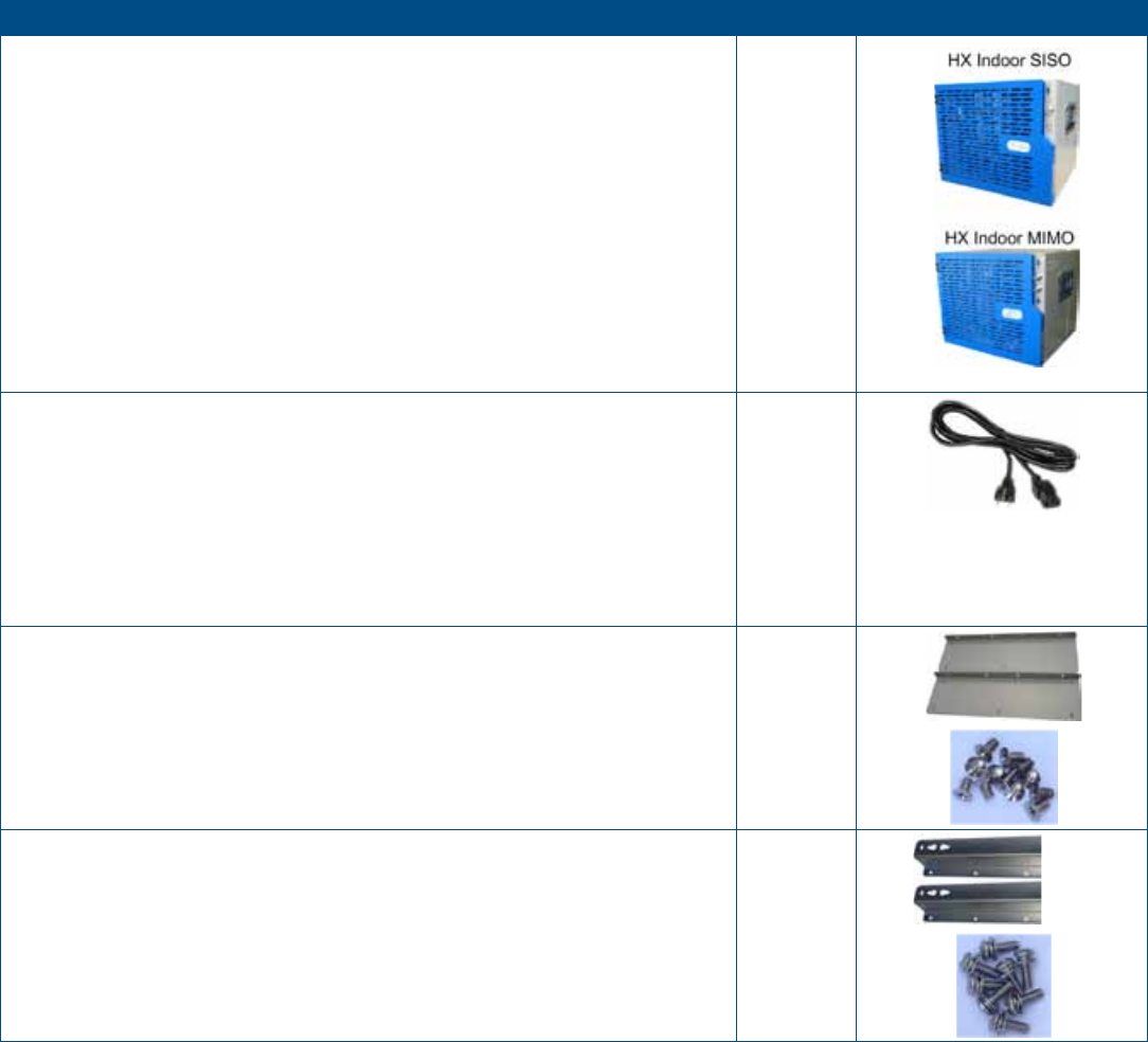
Description
Quantity
HX Indoor Cabinet (SISO/MIMO)
1
Power Cable (model dependent):
• AC USA: Cable power, straight, USA 10A, UL, Black,110V, L=1.8-2.5m
(70.8 – 98.4 in)
• AC Europe: Cable, power, W/Plug, 3Cond., Europe, L=1.8-2.5M (70.8
– 98.4 in)
• DC: Power cable with open edges, L=2 M (78.7 in)
Note: Image shown here is example of AC power cable
1
19-in Rack Brackets - used for rack-mount installations 2 (R/L)
Screws, 6-32X1/4,Flat HD, 100’, Philips – used for assembling the rack-
mount brackets on to the HX unit 12
Wall Mount Brackets – used for wall-mount installations 2 (R/L)
Screws, SEMS, 8-32X1/2,PAN, HD, Philips, Flat + Spring Washers – used
for assembling the wall mount brackets to the HX cabinet 8
Table 3-1. HX Indoor Package Items List
Corning Optical Communications User Manual I CMA-066-AEN I Page 28
3.2 Mounting
The HX Indoor unit is installed in the communication room via one of the following options (each type of installation requires
a different pair of brackets -both types supplied):
• Rack-mount
• Wall-mount (requires two people)
3.2.1 General Instructions
• Indoor type HX Remote Units should be installed in a communication room that provides access only to authorized
personnel. The units are maintenance free. In the event of failure, only authorized personnel should handle the units.
• Environmental Data - Maximum ambient operating temperature: 50° C
• Maximum ambient temperature in a rack: 45° C
3.2.2 Rack Mount Installation
Rack Installation General Safety Instructions
Review the following guidelines to help ensure your safety and protect the equipment from damage during the installation.
• Only trained and qualified personnel should be allowed to install or replace this equipment.
• Verify that ambient temperature of the environment does not exceed 50°C (122°F)
• To maintain a low center of gravity, ensure that heavier equipment is installed near the bottom of the rack and load the
rack from the bottom to the top.
• Ensure that adequate airflow and ventilation within the rack and around the installed components so that the safety of
the equipment is not compromised.
Corning Optical Communications User Manual I CMA-066-AEN I Page 29
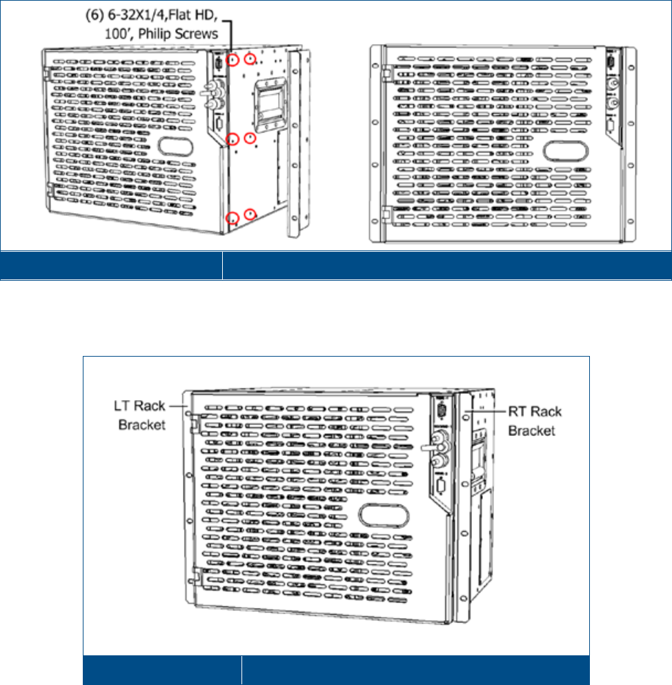
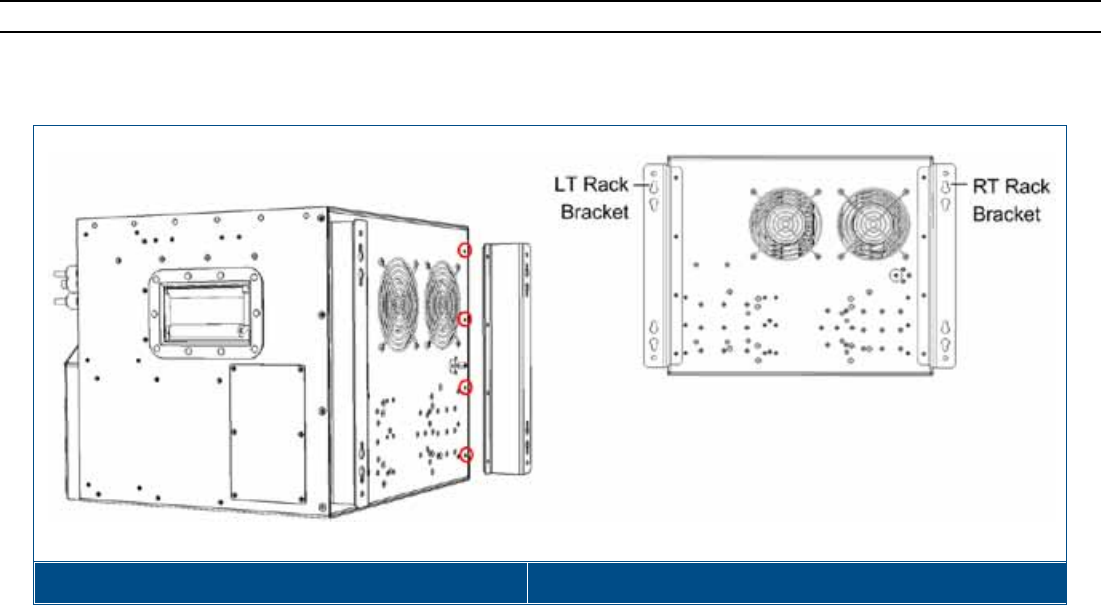
To install the unit in a rack
1. Assemble the Rack Mount Brackets to the side panels of the HX cabinet using the (12) supplied screws.
Assembling Rack Mount Brackets Figure 3-1
2. Install the unit in the 19-in communication rack and secure to the frame using the appropriate rack screws.
HX with Rack Brackets Figure 3-2
Corning Optical Communications User Manual I CMA-066-AEN I Page 30
3.2.3 Wall-Mount Installation
The wall-mount installation procedure references an installation on concrete walls/solid block walls.
3.2.3.1 Required/Recommended Tools and Materials for Wall Mount Installation
• Expanding lead shield anchors with 3/8” lag bolt with hex head bolts should be used (McMaster-Carr catalogue number
92403A200, or equivalent).
• Hex bolts need to be at least 3” in length
• Kobalt 3/8-in Drive Click 20 Ft-lbs - 100 Ft-lbs Torch Wrench Model #85601 or similar
• Kobalt Crows foot wrench
• Kobalt ratching wrench
• M18™ Cordless Lithium-Ion High-Performance ½” Hammer Drill/Driver
3.2.3.2 Mounting HX on Wall
Note: The HX unit should be mounted on concrete/hollow block walls only.
1. Assemble each wall-mount bracket to the side of the of the cabinet rear panel using the 8-32X1/2,PAN, HD, Philips, Flat
screws and washers (four per bracket). See Figure 3-3.
HX Indoor Unit with Assembled Wall-Mount Brackets Figure 3-3
Corning Optical Communications User Manual I CMA-066-AEN I Page 31
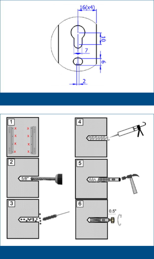
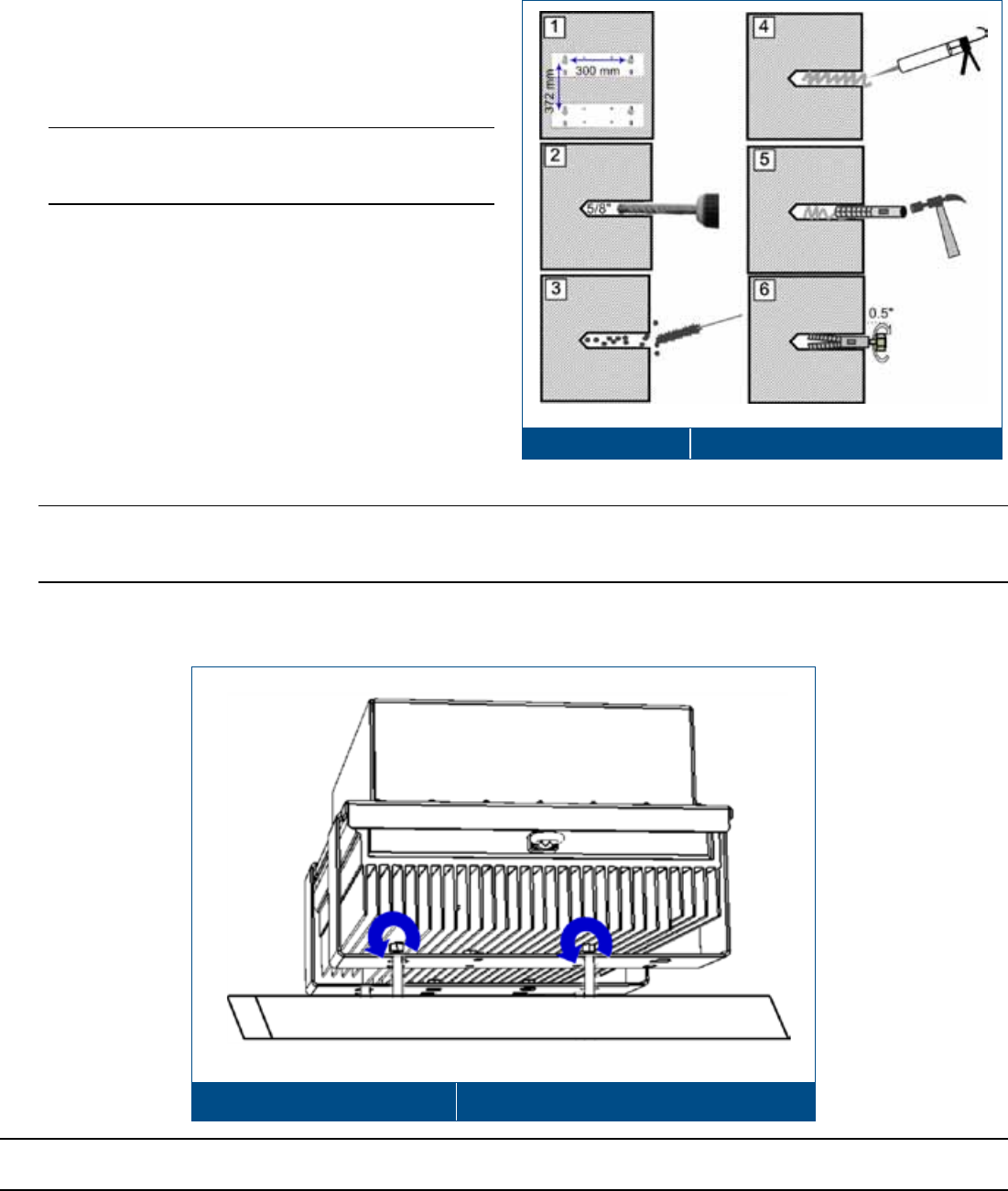
2. Referring to Figure 3-5, prepare the
appropriate anchors in wall:
• Using the bracket keyholes as guides,
mark the location of the four holes (two per
bracket) to be drilled in the wall. See
Figure 3-4 – dimension in mm).
• Using a hammer drill, drill holes for
expanding lead shield anchors. Refer to
Figure 3-4 for keyhole dimensions.
• Clean the debris from the anchor holes.
• Fill the 4 holes with silicon to help
weather-proof the drilled holes and to
prevent erosion.
• Tap in expanding lead shield anchors
• Insert bolts in anchors and tighten until
bolt head is 0.5” from surface of wall.
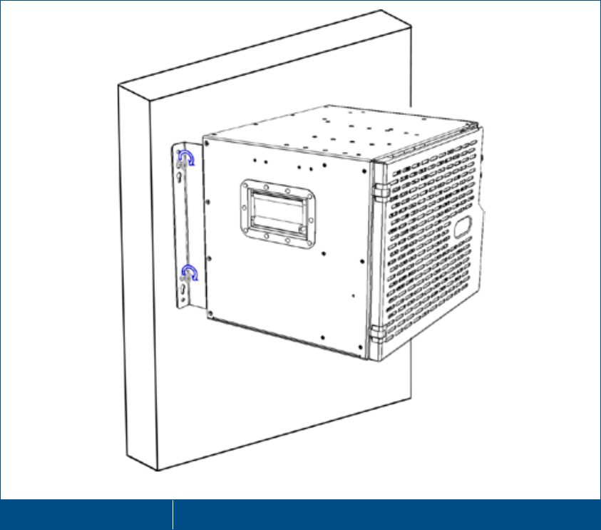
3. Mount the HX using key-hole designations
onto the 4 bolts. See Figure 3-6.
4. Tighten the 4 wall mount lag bolts with an
appropriate size wrench, socket or speed
wrench.
Wall Mount Bracket Keyhole Dimensions Figure 3-4
Inserting Anchors Figure 3-5
Corning Optical Communications User Manual I CMA-066-AEN I Page 32
Wall Mounted HX Indoor Figure 3-6
Corning Optical Communications User Manual I CMA-066-AEN I Page 33
3.3 Connections
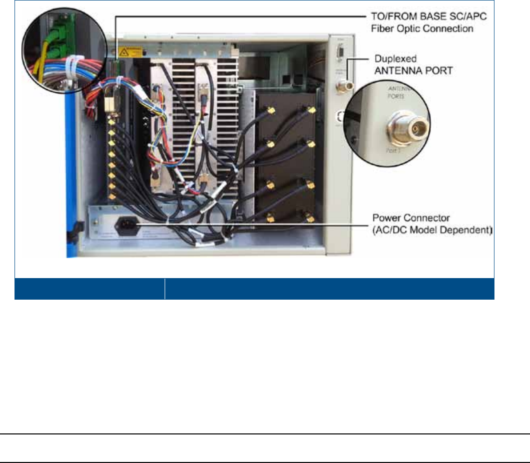
3.3.1 RF and Fiber Connections
Connect the HX Indoor unit RF and Fiber connections as follows
1. Connect broadband antenna coax to (duplexed) ANTENNA PORT (two for MIMO models) located on the right of the
cabinet front panel (external). See Figure 3-7.
2. Open cabinet door.
HX Indoor Connections – SISO Figure 3-7
3. Connect fiber as follows (two connections for MIMO models):
• Install splice box near Remote Cabinet.
• Connect fiber optic cable to splice box and the SC/APC pigtails to the HX RHU module (MIMO models include two
service modules with fiber connections).
• Downlink: Connect the fiber optic cable pigtails from splice box, which comes from the BU/OCH port, to the
corresponding RHU SC/APC TO BASE and FROM BASE optic ports of the service module(s).
• Uplink: Connect the fiber optic cable pigtails from splice box, which comes from the RHU service module(s), to the
uplink port that connects to the BU/OCH.
Note: Keep in mind the rules for handling and connecting F/O cables. The F/O cables will be connected to the
associated OCH in the communication room at a later phase.
Corning Optical Communications User Manual I CMA-066-AEN I Page 34
3.3.2 Ground Connection
• AC Cabinets - Mandatory
• DC Cabinets - Recommended
Connect the HX cabinet to the main grounding point in the rack via the terminal stud located on the rear of the unit
(ground wire with terminal not supplied).
Grounding Bolt Location – HX Rear Figure 3-8
3.3.3 Power Connections
The power supply connections depend on the HX model (AC or DC). Each type of model is supplied with corresponding
power cable.
Power Consumption for HX Indoor models:
• SISO: 340 W
• MIMO: 500 W
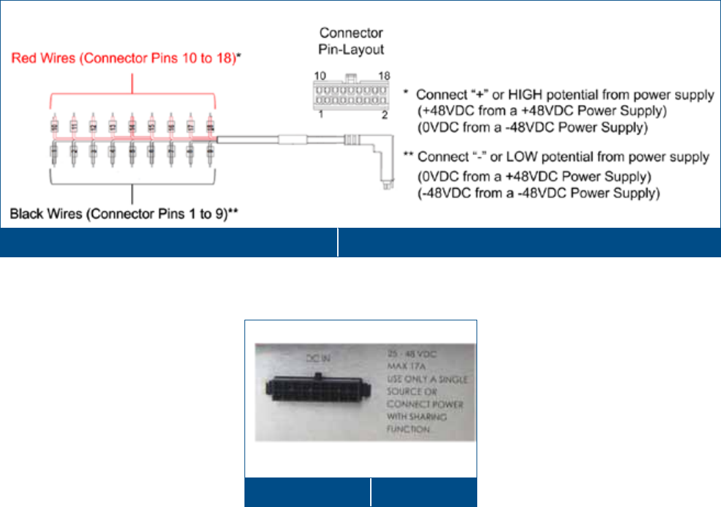
3.3.3.1 AC Models
Connect the supplied AC power cable to the HX AC power connector (100/240 VAC; 50/60 Hz; 8A Slow Blow Fuse) and to
the power source See Figure 3-9 for AC connector.
AC Connector Figure 3-9
Corning Optical Communications User Manual I CMA-066-AEN I Page 35
3.3.3.2 DC Models
DC Wiring
Note the following:
• The HX Indoor (DC model) 18 pin DC Input terminal block connector supports 20-30 AWG wires
• Maximum current allowed per pin: 5 A
1. Referring to Figure 3-13, connect wires as follows:
• Higher voltage wires from the DC source to RED wires of the DC cable jumper.
• Lower voltage wires to the BLACK wires of the cable jumper.
18-pair DC Cable and Connector Diagram Figure 3-10
2. Connect the DC cable jumper to ‘DC in’ power connector (see Figure 3-11).
DC Connector Figure 3-11
3. A voltmeter should read +48V when it’s negative side is connected to the black wire and positive side to red wire of the
HX jumper cable.
Corning Optical Communications User Manual I CMA-066-AEN I Page 36
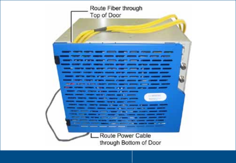
3.3.4 Routing Fiber and Power Cables
Route the fiber and power cables as follows (and close cabinet door):
• Fiber cables - route towards the top of the cabinet
• Power cable - route towards bottom of cabinet
Closed HX (MIMO) Cabinet with Routed Cables Figure 3-12
Corning Optical Communications User Manual I CMA-066-AEN I Page 38
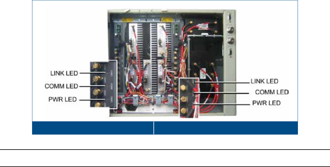
HX Unit Interfaces - 1.5.1.1 or 0 for complete description of LEDs.
The LED indicators are the same in both SISO and MIMO model service modules. Figure 3-13 shows an example of the
LEDs on the two service modules in a MIMO unit (SISO units only include one service module).
Location of HX Status LEDs (MIMO Model) Figure 3-13
Note: The HX monitoring and management capabilities are performed via the host OCH unit. Refer to the SC-450 User
Manual for the configuration and management options.
Corning Optical Communications User Manual I CMA-066-AEN I Page 39
4 HX Outdoor Physical Installation
4.1 General Information
• The HX Outdoor Remote Unit can be installed either on a wall or on a pole (brackets are provided to facilitate both
options).
• The unit weighs 40 kg (88.2 lbs). This requires two people or the use of a crane (from top ring) to lift the unit onto the
pole.
• The wall mount and pole mounting procedures described in this document are recommendations for the specified
scenarios. The installer should do the homework to use the proper hardware and industry standard mounting procedure
required for installing 88lbs unit on the varying types of wall & pole scenarios that could exist in the field.
• The wall mounting and pole mounting scenarios are modeled and simulated for hurricane and zone-4 earth quake
impact per GR-487 standard.
• All outdoor or weather/water exposed installations need to use stainless steel or hot-dipped galvanized anchors.
• The HX Outdoor unit must be mounted with the connectors facing down.
• The power connections are model dependent – refer to the wiring guide (supplied with each unit) for the connections to
the HX power connector.
• Ensure that the HX is properly grounded (refer to the grounding feature on the bottom port panel of the HX).
4.2 Unpacking and Inspection
Unpack and inspect the packages as follows:
1. Open the shipping carton and carefully unpack each unit from the protective packing material.
2. Verify that all the items have been received.
3. Check for signs of external damage. If there is any damage, call your Corning Optical Communications service
representative.
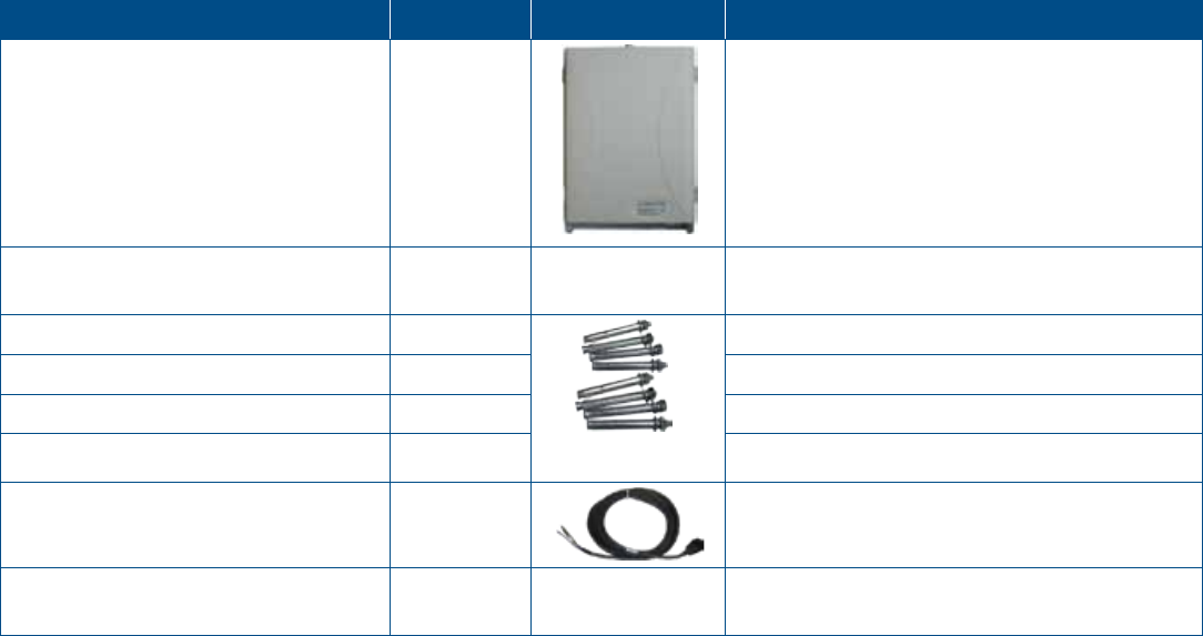
Description
Quantity
Image
P/N
HX Outdoor Remote Unit Cabinet 1
HX-C85P19L70A17-AC-B (or)
HX-C85P19L70A17-DC-B (or)
HX-C85G91D18U21-AC-B (or)
HX-C85G91D18U21-DC-B (or)
HX-G90D18U21-AC-B (or)
HX-G90D18U21-DC-B
Four Hole Bracket Template for
marking required holes for drilling
1
Flat Washer, 3/8" 8
631F000801
Nut,3/8, DIN 934 -3/8 UNC 8 631N001001
Spring Washer, 3/8" 8 631P000501
Hex Cap Screw, 3/8 x6", Head 9/16 8 631S002901
Power cable with open edges
Length=10 M.
1
HX Outdoor AC - 705A030451 (AC cable)
HX Outdoor DC - 705A030851 (DC Cable)
Conn. 1-20UNEF,Receptacle, solder
f/cable, waterproof
1 HX Outdoor AC - 616A010401 (3 Pins)
HX Outdoor DC - 616A011801 (8 Pins)
Corning Optical Communications User Manual I CMA-066-AEN I Page 40
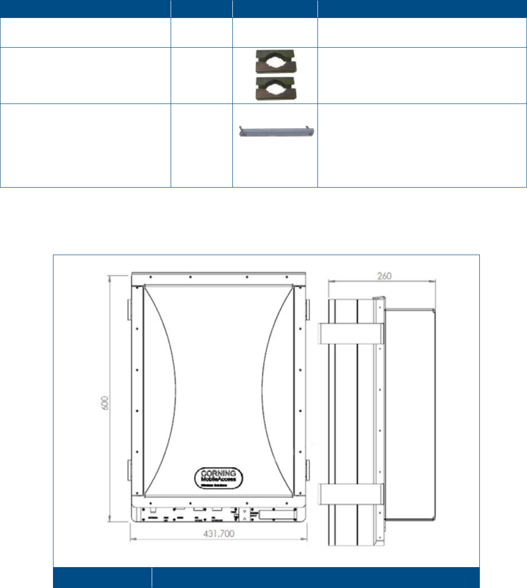
Description
Quantity
Image
P/N
Boot, straight, lipped, fluid-resistant
elastomer 23 to 10 mm
1 634A004501
Pole Clamp 4
264A088302
HX, Outdoor, Profile for wall
installation – iron bar used for
protecting the HX from vertical
displacement
1
264A174201
Anchor nut (JUMBO),HEX 1/2,NUT
7/16,L=60mm,inner 5/16, SS
2 631A004601
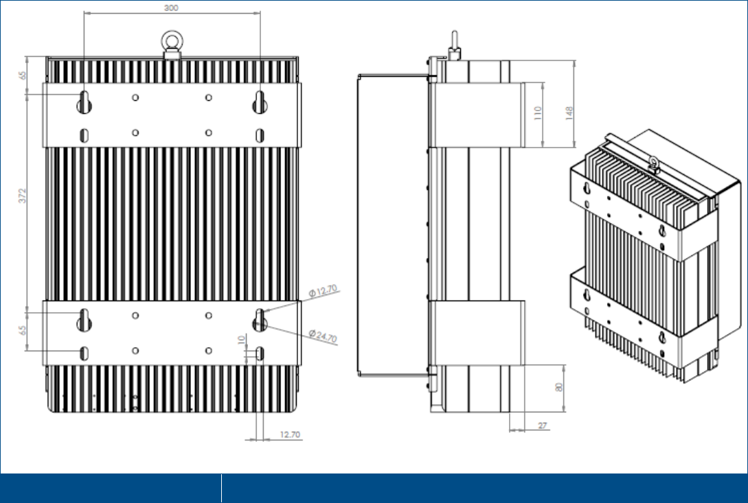
4.3 HX Outdoor Dimensions
The following figures show the HX Outdoor unit Figure 4-1 and bracket dimensions (Figure 4-2).
HX Unit Dimensions Figure 4-1
Corning Optical Communications User Manual I CMA-066-AEN I Page 41
HX Outdoor Bracket Dimensions Figure 4-2
4.4 Required/Recommended Tools and Materials for Wall Mount
Installation
• Expanding lead shield anchors with 3/8” lag bolt with hex head bolts should be used.
• Hex bolts need to be at least 3” in length
• Hex heads on bolts need to be >12.7 mm and <24.70 mm to fit bracket key-holes
• Recommended Anchor is Powers 3/8” Long lag shield with 3/8” X 3” HDG or SS Lag bolt or similar
• Kobalt 3/8-in Drive Click 20 Ft-lbs - 100 Ft-lbs Torch Wrench Model #85601 or similar
• Kobalt Crows foot wrench
• Kobalt ratching wrench
• M18™ Cordless Lithium-Ion High-Performance ½” Hammer Drill/Driver
Corning Optical Communications User Manual I CMA-066-AEN I Page 42
4.5 Mounting
4.5.1 Wall Mount Installation
Note the following:
• The wall-mount instructions provided in this section reference installations on concrete/ solid block /brick walls.
• The brackets required for mounting the unit on the wall are integrated in to the rear panel – no required assembly.
To wall-mount the HX Outdoor Remote Unit
1. Select the wall mount location according to the following criteria:
• General surroundings
• Shielded, ventilated, and easy-to-reach area (for maintenance and on-site inspection)
• Proximity to the antenna in order to minimize cable loss
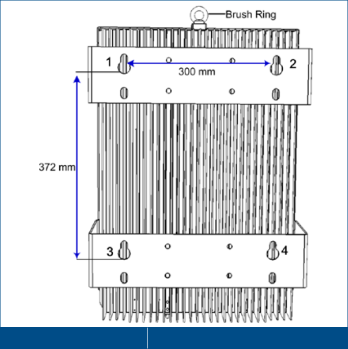
Bracket Holes for Wall Mount Figure 4-3
Corning Optical Communications User Manual I CMA-066-AEN I Page 43
2. Referring to Figure 4-4, insert the anchors for mounting
the unit as follows:
• Use the provided four hole template to mark the
location of the holes to be drilled in the wall.
Note: Key holes are 300 mm apart from each other
horizontally (center to center) and 372
mm apart
vertically (see Figure
4-3).
• Using a hammer drill, drill 5/8” holes for expanding
lead shield anchors.
• Clean the debris from the anchor holes.
• Fill the 4 holes with silicon to help weather-proof the
drilled holes and to prevent erosion.
• Tap in expanding lead shield anchors
• Insert bolts in anchors and tighten until bolt head is
0.5” from surface of wall.
Inserting Anchors Figure 4-4
3. Mount the HX using key-hole designations onto the four bolts.
Note: Brush ring (see Figure
4-3) is intended for the purpose of lifting the HX unit. However, it can also be used for
additional safety measure such as tethering the HX unit via the brush ring using a steel cable of sufficient strength to
withstand the units’ weight to an adequate alternate anchor point.
4. Reach behind the mounting bracket and tighten the 4 wall mount lag bolts with an appropriate size wrench, socket or
speed wrench. See Figure 4-5.
Bracket Holes for Wall Mount Figure 4-5
Note 1: If it is determined that a washer is needed for a secure installation the washer should not be more than 20 mm OD.
Note 2: Recommended torque = 8 ft/lb
Corning Optical Communications User Manual I CMA-066-AEN I Page 44
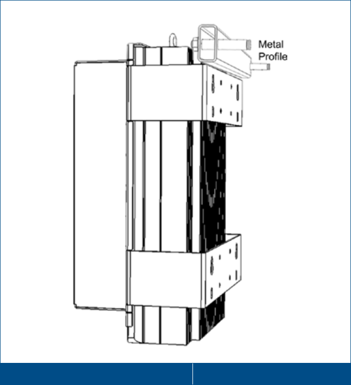
5. Referring to Figure 4-7, install the metal profile:
• Drill two holes for the profile anchors (provided), using the profile holes as a guide
• Place the metal profile behind the HX unit-above the bracket, insert the anchors in the wall and tighten
Wall Mounted HX OD with Metal Profile Figure 4-6
Corning Optical Communications User Manual I CMA-066-AEN I Page 45
4.5.2 Pole Mount Installation
The pole mount installation procedure consists of positioning the pole clamps on the pole and mounting the HX Outdoor unit
on them.
Note the following:
• Provided pole mounting accessories are designed for the pole radius thickness range, Ø63 – Ø95 mm
• The pole mount installation requires the following provided items (see section 4.2):
• (4) Pole clamps
• (8) Washer, Flat, 3/8"
• (8) Nut, 3/8, DIN 934 -3/8 UNC
• (8) Washer, Spring, 3/8"
• (8) Screw, Hex Cap, 3/8 x6", Head
To pole-mount the HX Outdoor Unit
1. Select the appropriate location according to the following criteria:
• Accessibility
• Antenna location and distance
2. Position and hold an outer top bracket on the pole.
3. Insert supplied spring washer and screw-hex-cap (four per bracket) momentarily support it with your hands.
4. Fit the screws through the inner clamp and secure loosely so that the distance between the clamps is adjustable.
Corning Optical Communications User Manual I CMA-066-AEN I Page 46
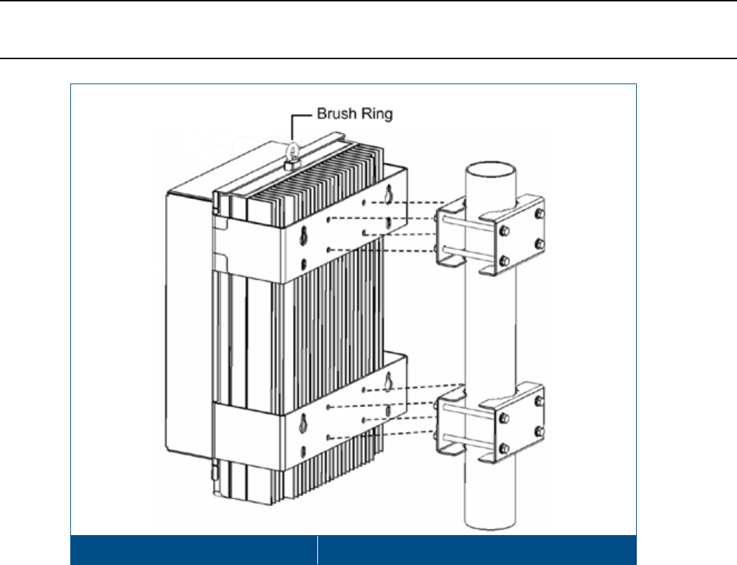
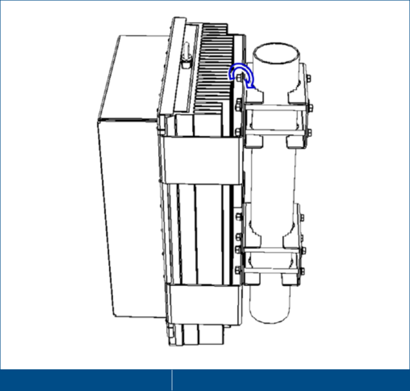
5. Lift the HX Unit and fit the clamp bolts into the four middle holes of each bracket, as shown in Figure 4-7:
• Top pole clamp bolts into top middle HX bracket holes
• Bottom pole clamp bolts into bottom middle HX bracket holes
Note: Brush ring (see Figure
4-7) is intended for the purpose of lifting the HX unit. However, it can also be used for
additional safety measure such as hanging the HX unit via the brush ring using a steel cable of sufficient strength and
tying it to an iron bar of enough strength.
Mounting HX OD Unit on Pole Clamp Figure 4-7
Corning Optical Communications User Manual I CMA-066-AEN I Page 48
4.6 Connections
The HX Outdoor connections are performed from the underside of the HX unit after it has been mounted. The main
connections include the RF, fiber and power connections. These connectors are waterproof and are protected by covers
when not connected. Remove the connector waterproof covers when connecting cables.
4.6.1 RF and Fiber Connections
To connect the RF and fiber cables
1. Connect the RF antenna coax cable to the HX ANTENNA port.
2. Connect the (Corning OptiTap®) fiber cable to the HX F/O UPLINK and F/O DOWNLINK OptiTap® connectors as
follows:
IMPORTANT! OptiTap™ pullout force ranges from a few lbs to 50+ lbs with the dust cap or connector installed. This
prevents damages caused to the DAS unit.
• Downlink: Connect the fiber optic cable from splice box, leading from the OCH port, to the corresponding F/O
DOWNLINK OptiTap®.
• Uplink: Connect the fiber optic cable from splice box, leading from the HX F/O UPLINK OptiTap® port, to the uplink
port leading to the OCH.
Note: Keep in mind the rules for handling and connecting F/O cables. The F/O cables will be connected to the
associated OCH in the communication room at a later phase.
HX RF and Fiber Connectors Figure 4-9
Corning Optical Communications User Manual I CMA-066-AEN I Page 49
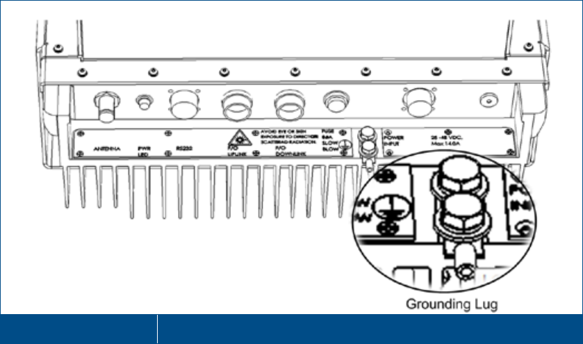
4.6.2 Ground Connection
The grounding connection is performed via a two hole, standard barrel grounding lug (LCD10-14A-L Panduit) located on the
HX connectors’ panel (see Figure 4-10):
• For use with stranded copper conductors
• 10-14 AWG
• Holes - ¼ inch
• STR
HX OD Grounding Lug Figure 4-10
Corning Optical Communications User Manual I CMA-066-AEN I Page 50
4.6.3 Power Connections
The HX Outdoor power connector is model dependant (AC/DC). Each HX Outdoor Remote unit includes a non-standard
power connector which requires the proper wiring. Wiring instructions are provided for both AC and DC models.
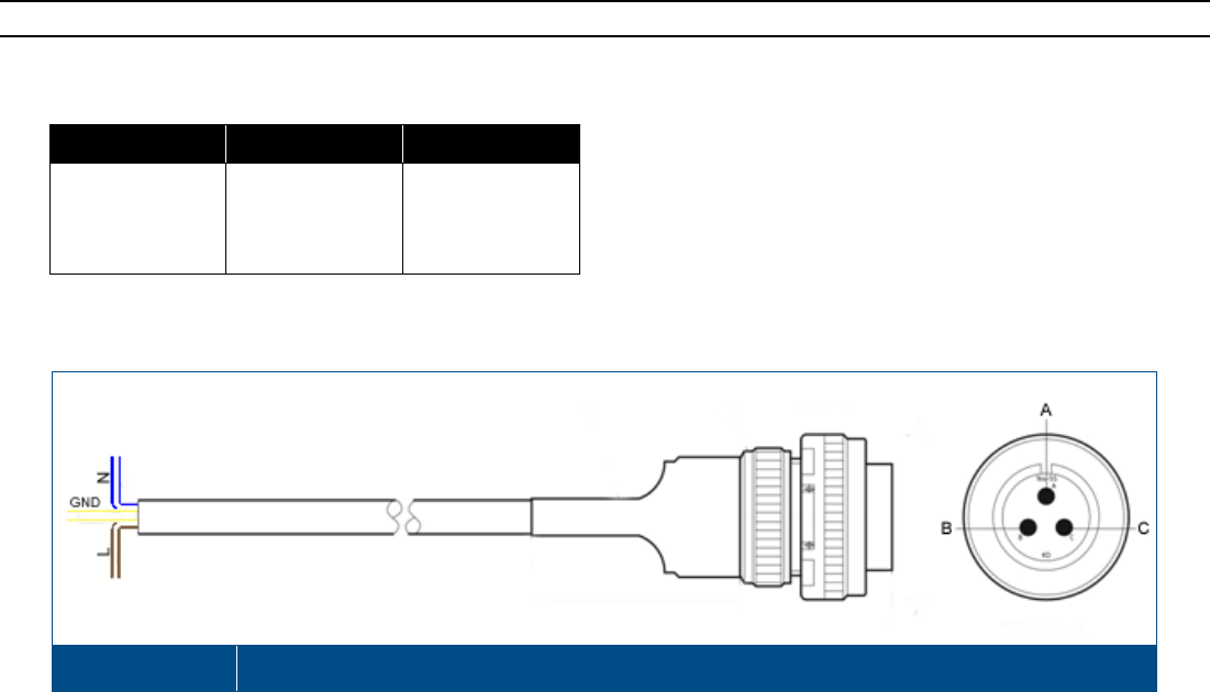
4.6.3.1 AC Power Input Model Connections
Note: Refer to Appendix D for the HX OD AC power cable specifications.
Connect the power cable wires according to the wire connection in Table 4-1 and Figure 4-11.
Pin
Wire Color
Function
A Yellow/Green GND
B Blue N
C Brown L
Table 4-1. Wire Connections
Wiring Diagram Figure 4-11
Corning Optical Communications User Manual I CMA-066-AEN I Page 51
4.6.3.2 DC Power Input Model Connections
Note: Refer to Appendix D for the HX OD DC power cable specifications.
General Information
• Length and tolerance of DC wire varies depending on ordered cable. See Table 4-2.
P/N
Length (Meter)
Tolerance (Meter)
705A030841 2 ± 0.1
705A030821 5 ± 0.5
705A030851 10 ± 0.1
705A030801 50 ± 0.5
705A030811 100 ± 0.5
705A030831 200 ± 0.5
Table 4-2. P/N and Length Table
• DC Input: 25-48 VDC
• No. of DC connector conductors: 8 (all four pairs are connected together – splitting the power evenly between them)
• DC Conductor size: 20 AWG
• At least 8A slow blow fuse
Connection Pinout
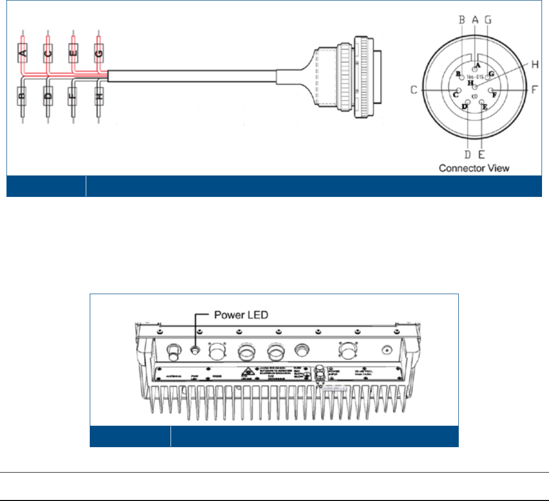
Connect the power cable wires according to the wire connection in Table 4-3 and Figure 4-12.
Wire Color
AWG
PIN
First Couple Red 20 A
Black 20 B
Second Couple Red 20 C
Black 20 D
Third Couple Red 20 E
Black 20 F
Fourth Couple Red 20 G
Black 20 H
Table 4-3. Wire Connections
Corning Optical Communications User Manual I CMA-066-AEN I Page 52
Wiring Diagram Figure 4-12
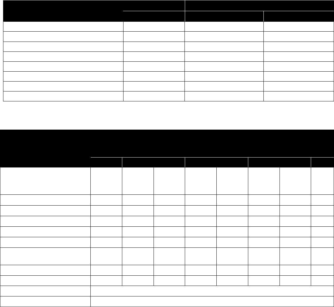
4.7 Verify Normal Operation
After the power connections have been completed, verify that the Power LED (located on the underside of the HX unit – see
section 1.5.2) is green.
Wiring Diagram Figure 4-13
Note: The HX monitoring and management capabilities are performed via the host OCH unit. Refer to the SC-450 User
Manual for the configuration and management options.
Corning Optical Communications User Manual I CMA-066-AEN I Page 53
5 Appendix A: System Specifications
5.1 RF Parameters
Supported Services
Frequency Range
Technologies
Band
Uplink
Downlink
LTE 700MHz 698-716 and 776-787 728-757
CDMA/LTE S-800 817-824 862-869
CDMA / WCDMA** / TDMA / GSM CELL850 824-849 869-894
GSM / GPRS / WCDMA / HSPA / LTE* EGSM900 880-915 925-960
GSM / GPRS / WCDMA / HSPA / LTE* DCS1800 1710-1785 1805-1880
CDMA / WCDMA** / TDMA / GSM PCS1900 1850-1915 1930-1995
WCDMA** / HSPA AWS3 1700 1710-1778 2110-2180
WCDMA / HSPA / LTE* UMTS2100 1920-1980 2110-2170
(*) WCDMA service is based on 3GPP standards, LTE service may be deployed in the future due to frequency re-farming planned by the operators.
(**) WCDMA service is based on 3GPP2 CDMA2000 standards.
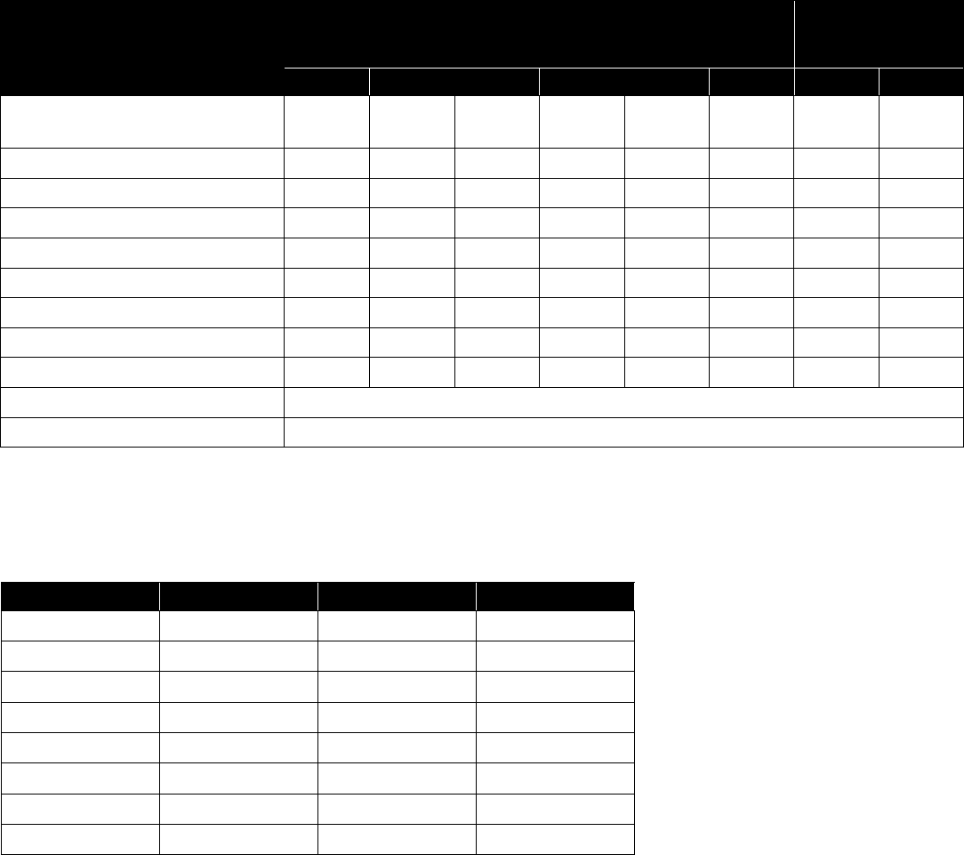
RF Parameters per Low-Band Service
HX RF Parameters
LTE
700 MHz
CELL TDMA
CDMA/WCDMA
850 MHZ
CDMA/LTE
S-800 MHz +
CELL/TDMA/CDMA/
WCDMA 850 MHz
GSM/ E-GSM
900 MHz
DL
UL
DL
UL
DL
UL
DL
UL
Max Output Power Per
Antenna Port
1 Operator (Composite)
33 33* 33 29
2 Operators 30 30 30 26
4 Operators 27 27 27 23
8 Operators - 24 24 20
Mean Gain (dB) 1 33 11 33 11 33 11 29 16
Pin (dBm) 0 0 0
Input IP3 (dBm) AGC OFF
Typical -10
-10
-10
-10
Max Intermod Distortion (dBm) -13**
-13**
-13**
-36*
NF (dB) at Max Gain 7
7
7 7
Gain Flatness/Ripple (dB) 2 +/-1.5
Max. Noise Level 44
* WCDMA compiles with 3GPP TS 25.106 V5.0.0 (2002-03) table 9.4 spectrum emission mask.
** Out of band and spurious emissions compliant to FCC.
1Factory set mean gain BU-HX without RIU. May be field adjusted using controller system.
2Gain Flatness/Ripple is specified for the non-duplexed port of the system.
Corning Optical Communications User Manual I CMA-066-AEN I Page 54
RF Parameters per High-Band Service
HX RF Parameters
DCS
1800 MHZ
AWS3
CDMA/WCDMA
1700 MHZ
PCS
CDMA/WCDMA
1900 MHz
UMTS
2100 MHz
DL
UL
DL
UL
DL
UL
DL
UL
Max Output Power Per Antenna Port
1 Operator (Composite) 32 33 33 29
2 Operators 29 30 30 26
4 Operators 26 27 27 23
8 Operators 23 24 24 20
Mean Gain (dB) 1 32 16 33 11 33 11 33 16
Pin (dBm) 0 0 0 0
Input IP3 (dBm) AGC OFF Typical -10 -10 -10 -10
Max Intermod Distortion (dBm) -30*
-13*
-13*
13*
NF (dB) at Max Gain 7
7
7 7
Gain Flatness/Ripple (dB) 2 +/- 2.0
Max. Noise Level 44
* WCDMA compiles with 3GPP TS 25.106 V5.0.0 (2002-03) table 9.4 spectrum emission mask.
** Out of band and spurious emissions compliant to FCC.
1Factory set mean gain BU/OCH-HX without RIU. May be field adjusted using controller system.
2Gain Flatness/Ripple is specified for the non-duplexed port of the system.
Coupling Specifications*
Frequency (MHz)
Coupling (dB)
Frequency (MHz)
Coupling (dB)
700 -48.0 2100 -39.0
800 -47.1 2200 -38.5
900 -46.1 2500 -37.4
1000 -45.0 2600 -37.0
1700 -40.7 2700 -36.7
1800 -40.1
1900 -39.7
2000 -40.7
*Coupling specifications are only relevant to HX models with integrated Test Ports (refer to ordering information section of this Specifications Sheet)

Corning Optical Communications User Manual I CMA-066-AEN I Page 55
5.2 Optical Specifications
Optical Output Power <3.0 mW
Max. Optical Budget 2 dB for fiber + 1 dB for connectors (assumed) = 3 dB total. 300 m Multi-mode
Optical Loss per Mated-pair
Connectors 0.5 dB (max)
Optical Connector Indoor: SC/APC
Outdoor: Corning OptiTap®
Fiber Type
Single-mode: 9/125µm
Multi-mode: 50/125 µm or 62.5/125µm (Minimum qualifications with ANSI/TIA/EIA-
568-B series, EN50173-1 or ISO/IEC 11801)
Wavelength 1310 ± 10 nm
Maximum Distance Between Base
Unit and Remote Cabinet
2 km for SMF
5.3 Physical Specifications
5.3.1 Indoor Remote Unit
Ports One SC/APC fiber-optic pair connector or two for MIMO models
One N-Type female 50Ω connector for antenna (two connectors for MIMO models)
One Power connector (model dependent):
• AC models: One power connector for 90-264VAC power feed
• DC models: One 18 pin power connector for 25-48VDC power feeds
One D-Type 9 pins RS-232 connector (or two for MIMO models) for local craft
Two SMA type Test Port connectors (one UL and one DL) – model dependant
Power HX Indoor AC: 90-264 VAC; FUSE,250V/8A,5x20mm, slow blow fuse
HX Indoor DC: 25-48V DC; 18 pin connector supports 20-
30 AWG wires; Max. current
(per pin) = 5A
Max Power Consumption: 350 W (SISO models), 500 W (MIMO models)
Fuses: Includes two internal fuses
Physical Characteristics Mounting: Wall or Rack
Dimensions (H x W x D): 13.8 x 16.9 x 14.9 in (350 x 429 x 378 mm)
Weight: Three Services SISO configuration: 66 lbs (30 kg)
Four Services SISO configuration: 71 lbs (32 kg)
Two SISO and two MIMO services configuration: 92 lbs (42 kg)
Cooling Feature Active heat dissipation (Fan)

Corning Optical Communications User Manual I CMA-066-AEN I Page 56
5.3.2 Outdoor Remote Unit
Ports
(2)
Corning OptiTap® fiber optic waterproof connectors (1 for UL and 1 for DL)
(1)
N-Type female 50Ω connector for antenna
(1)
Waterproof power connector – model dependent:
• AC model: 1-20UNEF, plug, 3-pin waterproof, solder for panel, power connector for
100/240 VAC power feed
• DC model: 1-20UNEF, plug, 8-pin waterproof , solder for panel, power connector for 25-
48 VDC power feed
(1)
D-Type 9 pins RS-232 waterproof connector for local craft
(2)
SMA type Test Port connectors (one UL and one DL) – model dependant
Power • HX Outdoor AC: 100/240 VAC; FUSE,250V/8A,6.35x32 mm, slow blow
• HX Outdoor DC: 25-48V DC; FUSE,250V/16A,6.35x32 mm, slow blow
• Max Power Consumption: 340 W
Physical
Characteristics
Mounting: Wall or Pole
Dimensions (H x W x D) (mm): 24.2’’* x17.5’’x 11.4’’ (615* x 442 x 285.3)
*without ‘Brush Ring’
Weight (four services configuration): 88 lbs (40 kg)
Cooling Feature Passive heat dissipation (Heat Sink)
5.4 Environmental Specifications
Indoor Remote Unit
Outdoor Remote Unit
Operating
Temperature 0°C to +50°C (32°F to 122°F) -30°C to +65°C (-22°F to 149°F)
Storage Temperature -20° to 85°C (-4° to 185°F) -20° to 85°C (-4° to 185°F)
Humidity 10% to 90%, non-condensing 10% to 90%, non-condensing
Enclosure -
NEBS OSP Class 4 rated (Enclosure protected from
elements and waterproofing)
5.5 Standards and Certifications
Laser Safety
• CDRH 21 CFR 1040.10, 1040.11 (Except for deviations per notice No.50, July 26, 2001)
• IEC 60825-1, Amendment 2 (January 2001)
• EN 60825-1
CE
Radio Equipment and Systems:
• EN 301 502 – for GSM / EGSM Frequency Bands
• EN 300 609 – for DCS Frequency Band
• EN 301 893 – for WLAN 802.11a EN 301 908 – for UMTS Frequency Band
EMC: EN 301 489
FCC
Radio Equipment and Systems:
• FCC 47 CFR Part 22 – for CELL Frequency Band
• FCC 47 CFR Part 24 – for PCS Frequency Band
• FCC 47 CFR Part 27 – for 700 LTE and AWS Frequency Bands
EMC: FCC 47 CFR Part 15 Subpart B
Safety
• EN 60950; UL 60950

Corning Optical Communications User Manual I CMA-066-AEN I Page 57
• CAN/CSA-C22.2 No.60950

Corning Optical Communications User Manual I CMA-066-AEN I Page 58
6 Appendix B: Ordering Information
Note: The information listed below is updated up to the document publishing date. Refer to the HX datasheet for the most
updated ordering information.
6.1 HX Indoor Remote Units (SISO and MIMO)
Service Supported
Part Number
Description
CELL/PCS/700LTE/AWS
SISO Services
HX-C85P19L70A17-AC-A HX Quad-service Indoor CELL, PCS, AWS and 700 MHz
LTE SISO solution supporting local AC power, SMF
HX-C85P19L70A17-DC-A HX Quad-service Indoor CELL, PCS, AWS and 700 MHz
LTE SISO solution supporting remote DC power, SMF
HX85197017U80-ACAT HX-Quad-service indoor CELL, PCS, AWS and 700 MHz
LTE SISO solution supporting remote DC power, SMF;
Includes test ports; upgradeable to add Sprint’s 800 MHz
band
HX85197017U80-DCAT HX-Quad-service indoor CELL, PCS, AWS and 700 MHz
LTE SISO solution supporting local AC power, SMF;
Includes test ports; upgradeable to add Sprint’s 800 MHz
band
CELL/PCS/700LTE-
MIMO/AWS-MIMO
HX-C85P19L70MA17M-AC-A HX Quad-service Indoor CELL, PCS, AWS MIMO and 700
MHz LTE MIMO solution supporting local AC power, SMF
HX-C85P19L70MA17M-DC-A HX Quad-service Indoor CELL, PCS, AWS MIMO and 700
MHz LTE MIMO solution supporting remote DC power,
SMF
CELL/S-800/
PCS/700LTE/AWS
HX8085197017-AC-AT HX-5 band Indoor CELL, S-800, PCS, AWS and 700 MHz
LTE SISO solution; supporting local AC power; SMF;
Includes test ports
HX8085197017-DC-AT HX-5 band Indoor CELL, S-800, PCS, AWS and 700 MHz
LTE SISO solution; supporting local DC power; SMF;
Includes test ports
CELL/GSM/DCS/UMTS
SISO Services
HX-C85G91D18U21-AC-A HX Quad-service indoor CELL, GSM Partner, DCS, and
UMTS SISO solution supporting local AC power, SMF
HX-C85G91D18U21-DC-A HX Quad-service indoor CELL, GSM Partner, DCS, and
UMTS SISO solution supporting remote DC power, SMF
GSM/DCS/UMTS
SISO Services
HX-G90D18U21-AC-A HX Tri-service Indoor GSM, DCS and UMTS SISO
solution supporting local AC power, SMF
HX-G90D18U21-DC-A HX Tri-service Indoor GSM, DCS and UMTS SISO
solution supporting remote DC power, SMF
GSM/DCS/UMTS
MIMO Services
HX-G90MD18U21M-AC-A HX Tri-service Indoor GSM MIMO, DCS and UMTS MIMO
solution supporting local AC power, SMF
HX-G90MD18U21M-DC-A HX Tri-service Indoor GSM MIMO, DCS and UMTS MIMO
solution supporting remote DC power, SMF

Corning Optical Communications User Manual I CMA-066-AEN I Page 59
6.2 HX Remote Outdoor Units (SISO services)
Service Supported
Part Number
Description
CELL/PCS/700LTE/AWS HX-C85P19L70A17-AC-B HX Quad-service Outdoor CELL, PCS, AWS and 700
MHz LTE solution supporting local AC power, SMF
HX-C85P19L70A17-DC-B HX Quad-service Outdoor CELL, PCS, AWS and 700
MHz LTE solution supporting remote DC power, SMF
HX85197017U80-AC-B HX Quad-service Outdoor CELL, PCS, AWS and 700
MHz LTE solution; supporting local AC power; includes
test ports; upgradeable to add Sprint’s 800 MHz band;
SMF
HX85197017U80-DC-B HX Quad-service Outdoor CELL, PCS, AWS and 700
MHz LTE solution; supporting remote DC power; includes
test ports; upgradeable to add Sprint’s 800 MHz band;
SMF
CELL/GSM/DCS/UMTS HX-C85G91D18U21-AC-B HX Quad-service Outdoor CELL, GSM
Partner, DCS and UMTS solution supporting local AC
power, SMF
HX-C85G91D18U21-DC-B HX Quad-service Outdoor CELL, GSM
Partner, DCS and UMTS solution supporting remote DC
power, SMF
GSM/DCS/UMTS HX-G90D18U21-AC-B HX Tri-service Outdoor GSM, DCS and UMTS
solution supporting local AC power, SMF
HX-G90D18U21-DC-B HX Tri-service Outdoor GSM, DCS and UMTS solution
supporting remote DC power, SMF
CELL/S-
800/PCS/700LTE/AWS
HX8085197017-AC-B HX-5 band Outdoor CELL, S-800, PCS, 700 MHz LTE
and AWS solution supporting local AC power, SMF
HX8085197017-DC-B HX-5 band Outdoor CELL, S-800, PCS, 700 MHz LTE
and AWS solution supporting local AC power, SMF

Corning Optical Communications User Manual I CMA-066-AEN I Page 60
6.3 Accessory Kits
Part Number
Description
AK-HX-SW-4B-2-5B Accessory kit with hardware and software to upgrade the HX-quad band upgradable units to
add Sprint’s 800MHz band
6.4 Optical Central Hub (OCH) - HX International products
Part Number
Description
OCH-HX-4-SMF Optical Central Hub for SISO services, supporting (4) SISO HX units, SM
OCH-HX-8-SMF Optical Central Hub for SISO or MIMO Services, supporting (8) SISO or (4) MIMO HX units, SM
6.5 Corning OptiTap™ Cables
Part Number
Description
434401EB4R2005M-P OptiTap® to SC/APC 5 meters
434401EB4R2030M-P OptiTap® to SC/APC 30 meters
434401EB4R2100M-P OptiTap®to SC/APC 100 meters
Note: The listed OptiTap cables are available on demand within a week of the order. Custom length cables require longer
lead times. For more information contact your Corning account manager.

Corning Optical Communications User Manual I CMA-066-AEN I Page 61
7 Appendix C: HX Outdoor Non-Standard
Connector Descriptions
Table 7-1 provides a description of the HX Outdoor RS232 and power (AC or DC) connectors.
Connector
Manufacturer Name
Manufacturer P/N
Description
AC Power KUKDONG KD3100A16S-5P-A02 CONN, 1-20UNEF, PLUG,3
PINS ,SOLDER FOR
PANNEL,WATERPROOF
DC Power KUKDONG KD3100A16S-01P-A02 CONN, 1-20UNEF, PLUG,8
PINS ,SOLDER FOR
PANNEL,WATERPROOF
RS232
Note: Used for local
setup and maintenance
by technical personnel
KUKDONG KD3100A14SA10P-A02
CONN, 7/8-
20UNEF,PLUG,10 PINS
,SOLDER FOR
PANNEL,WATERPROOF
Table 7-1. Non-Standard Connectors Descriptions
Corning Optical Communications User Manual I CMA-066-AEN I Page 62
8 Appendix D: Power Cable Specifications
8.1 AC Power Cable Specifications
Use the following cable: TELDOR, Manufacturer P/N 3318300101 (or equivalent).
Conductor Material:
Bare Copper
Conductor Size:
18 AWG
Conductor Construction:
42 x 0.16 mm
Insulation Material:
PVC
Insulation Thickness:
0.6 mm
Insulation O.D.:
2.4 mm nom.
Conductor Color Code:
Brown, Blue, Yellow/Green
Total Number of Elements:
3
Outer Jacket Thickness:
0.9 mm nom.
Outer Jacket Color:
Black
Marking:
Teldor Standard
8.2 DC Power Cable Specifications
Use the following cable: TELDOR, Manufacturer P/N 3320800101 (or equivalent).
Conductor Material:
Bare Copper
Conductor Size:
20 AWG
Conductor Construction:
19 x 0.20 mm
Insulation Material:
FR-PVC
Insulation O.D.:
2.0 mm nom.
Conductor Color Code:
4 Black; 4 Red
Outer Jacket Thickness:
0.9 mm nom.
Outer Jacket Color:
Black
Corning Optical Communications LLC • PO Box 489 • Hickory, NC 28603-0489 USA
800-743-2675 • FAX: 828-325-5060 • International: +1-828-901-5000 • www.corning.com/opcomm
Corning Optical Communications reserves the right to improve, enhance, and modify the features and specifications of Corning Optical Communications
products without prior notification. A complete listing of the trademarks of Corning Optical Communications is available at
www.corning.com/opcomm/trademarks. All other trademarks are the properties of their respective owners. Corning Optical Communications is ISO 9001
certified. © 2015, 2016 Corning Optical Communications. All rights reserved. CMA-066-AEN / August 2016
P/N
709C006803 Rev A00