Corning Optical Communication LITENNA9B430P4 In Building Repeater User Manual litenna 4 2 fh8

Corning Optical Communication Wireless In Building Repeater litenna 4 2 fh8

Contents

Specification data sheet

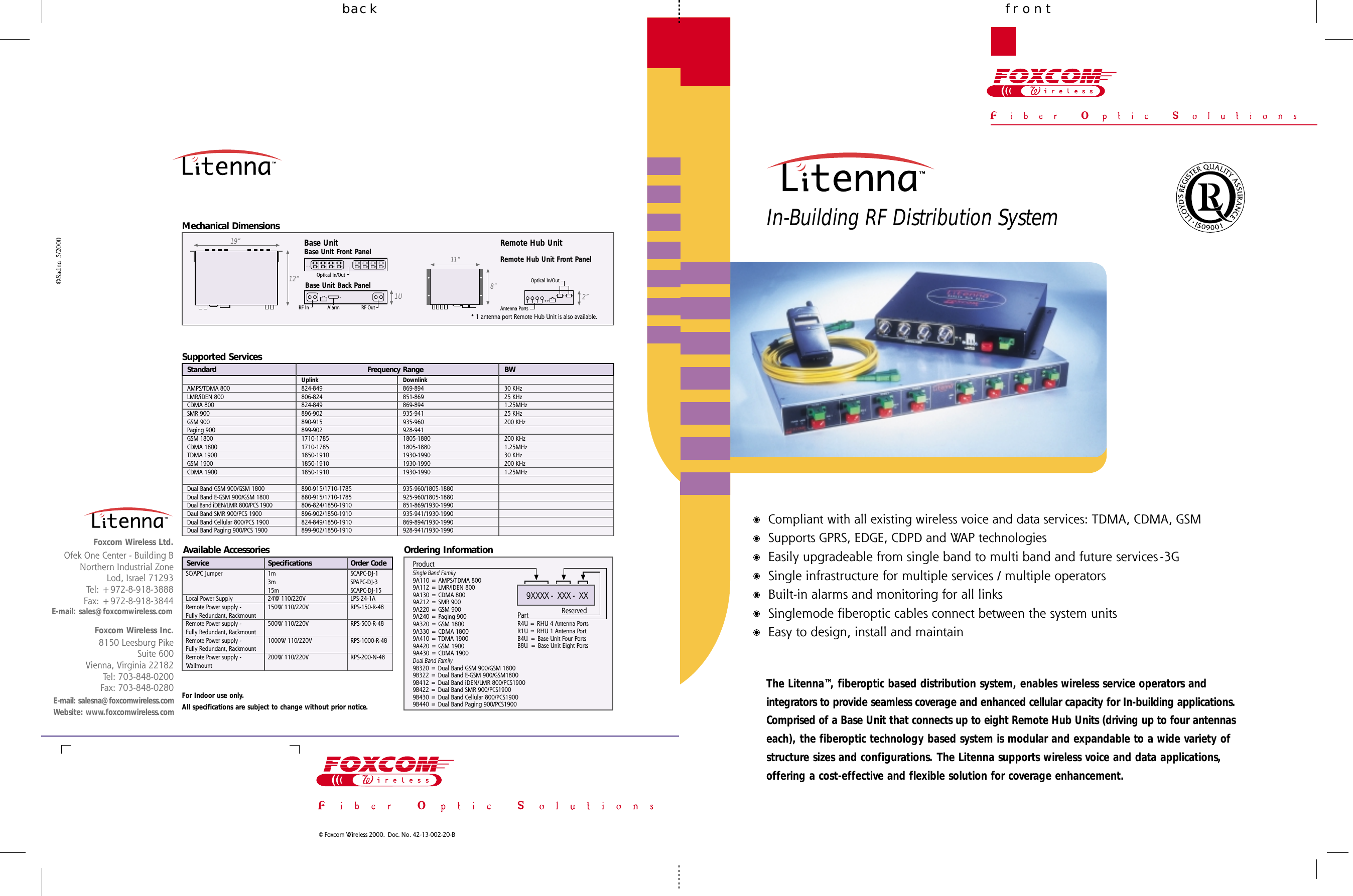
frontbackIn-Building RF Distribution System©Sadna  5/2000© Foxcom Wireless 2000.  Doc. No. 42-13-002-20-BE-mail: salesna@foxcomwireless.comWebsite: www.foxcomwireless.com8150 Leesburg PikeSuite 600Vienna, Virginia 22182Tel: 703-848-0200Fax: 703-848-0280Foxcom Wireless Inc.Ofek One Center - Building BNorthern Industrial ZoneLod, Israel 71293Tel: +972-8-918-3888Fax: +972-8-918-3844Foxcom Wireless Ltd.Frequency RangeAMPS/TDMA 800LMR/iDEN 800CDMA 800SMR 900GSM 900Paging 900GSM 1800CDMA 1800TDMA 1900GSM 1900CDMA 1900Dual Band GSM 900/GSM 1800Dual Band E-GSM 900/GSM 1800Dual Band iDEN/LMR 800/PCS 1900Daul Band SMR 900/PCS 1900Dual Band Cellular 800/PCS 1900Dual Band Paging 900/PCS 1900Uplink824-849806-824824-849896-902890-915899-9021710-17851710-17851850-19101850-19101850-1910890-915/1710-1785880-915/1710-1785806-824/1850-1910896-902/1850-1910824-849/1850-1910899-902/1850-1910Downlink869-894851-869869-894935-941935-960928-9411805-18801805-18801930-19901930-19901930-1990935-960/1805-1880925-960/1805-1880851-869/1930-1990935-941/1930-1990869-894/1930-1990928-941/1930-1990SpecificationsSC/APC JumperLocal Power SupplyRemote Power supply -Fully Redundant, RackmountRemote Power supply -Fully Redundant, RackmountRemote Power supply -Fully Redundant, RackmountRemote Power supply -Wallmount1m3m15m24W 110/220V150W 110/220V500W 110/220V1000W 110/220V200W 110/220VSCAPC-DJ-1SPAPC-DJ-3SCAPC-DJ-15LPS-24-1ARPS-150-R-48RPS-500-R-48RPS-1000-R-48RPS-200-N-48Order CodeBW30 KHz25 KHz1.25MHz25 KHz200 KHz200 KHz1.25MHz30 KHz200 KHz1.25MHzOrdering InformationProductSingle Band Family9A110 = AMPS/TDMA 8009A112 = LMR/iDEN 8009A130 = CDMA 8009A212 = SMR 9009A220 = GSM 9009A240 = Paging 9009A320 = GSM 18009A330 = CDMA 18009A410 = TDMA 19009A420 = GSM 19009A430 = CDMA 1900Dual Band Family9B320 = Dual Band GSM 900/GSM 18009B322 = Dual Band E-GSM 900/GSM18009B412 = Dual Band iDEN/LMR 800/PCS19009B422 = Dual Band SMR 900/PCS19009B430 = Dual Band Cellular 800/PCS19009B440 = Dual Band Paging 900/PCS1900ReservedPartR4U = RHU 4 Antenna PortsR1U = RHU 1 Antenna PortB4U = Base Unit Four PortsB8U  = Base Unit Eight Ports9XXXX -  XXX -  XXSupported ServicesAvailable AccessoriesE-mail: sales@foxcomwireless.comFor Indoor use only.All specifications are subject to change without prior notice.The Litenna™, fiberoptic based distribution system, enables wireless service operators andintegrators to provide seamless coverage and enhanced cellular capacity for In-building applications.Comprised of a Base Unit that connects up to eight Remote Hub Units (driving up to four antennaseach), the fiberoptic technology based system is modular and expandable to a wide variety ofstructure sizes and configurations. The Litenna supports wireless voice and data applications,offering a cost-effective and flexible solution for coverage enhancement.Compliant with all existing wireless voice and data services: TDMA, CDMA, GSMSupports GPRS, EDGE, CDPD and WAP technologiesEasily upgradeable from single band to multi band and future services -3GSingle infrastructure for multiple services / multiple operatorsBuilt-in alarms and monitoring for all linksSinglemode fiberoptic cables connect between the system unitsEasy to design, install and maintainStandardServiceMechanical DimensionsRemote Hub Unit19”12”1UBase UnitBase Unit Front PanelBase Unit Back Panel11”8”Remote Hub Unit Front PanelRF In RF OutAlarmOptical In/OutOptical In/OutAntenna Ports2”* 1 antenna port Remote Hub Unit is also available.
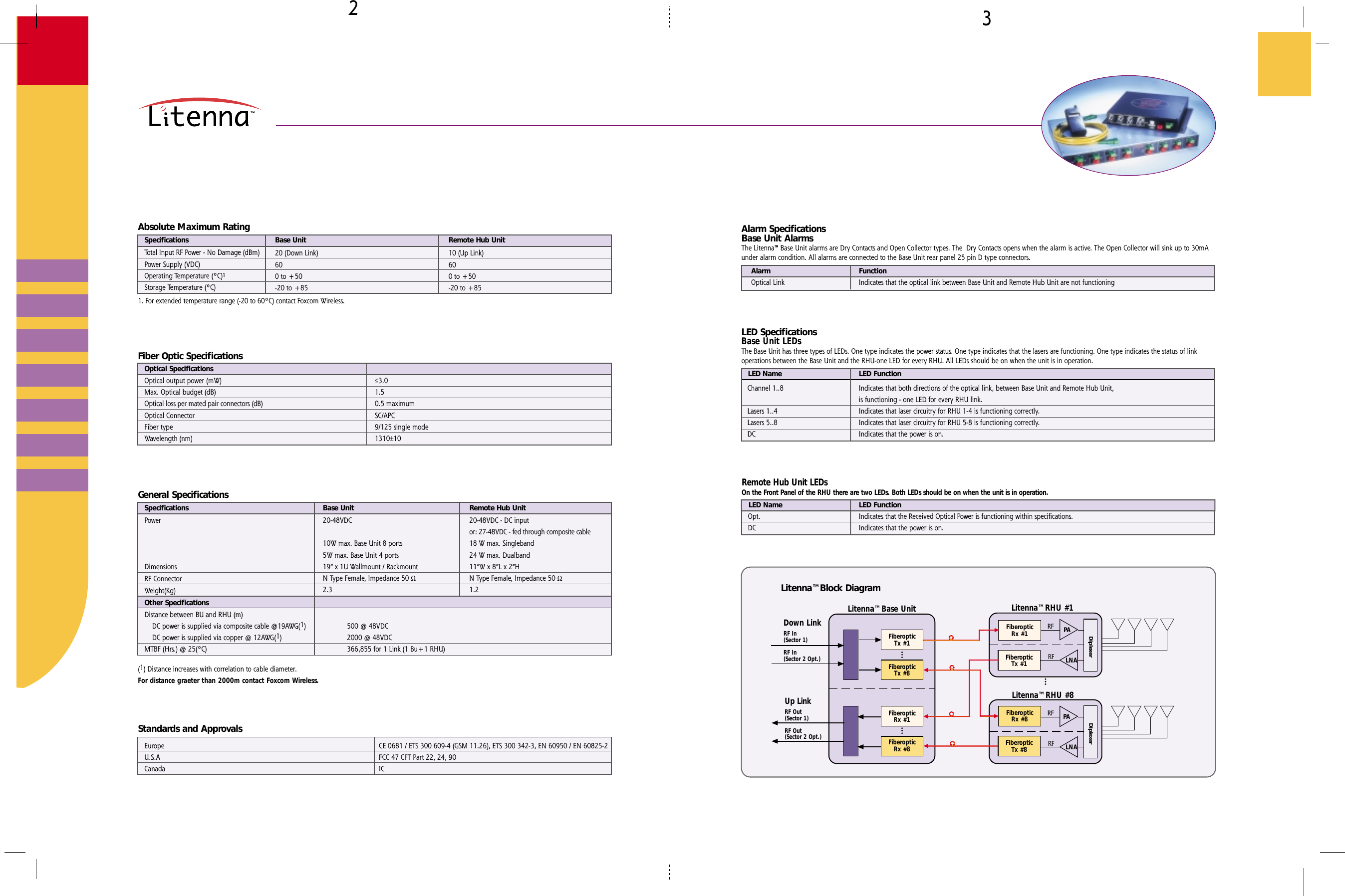
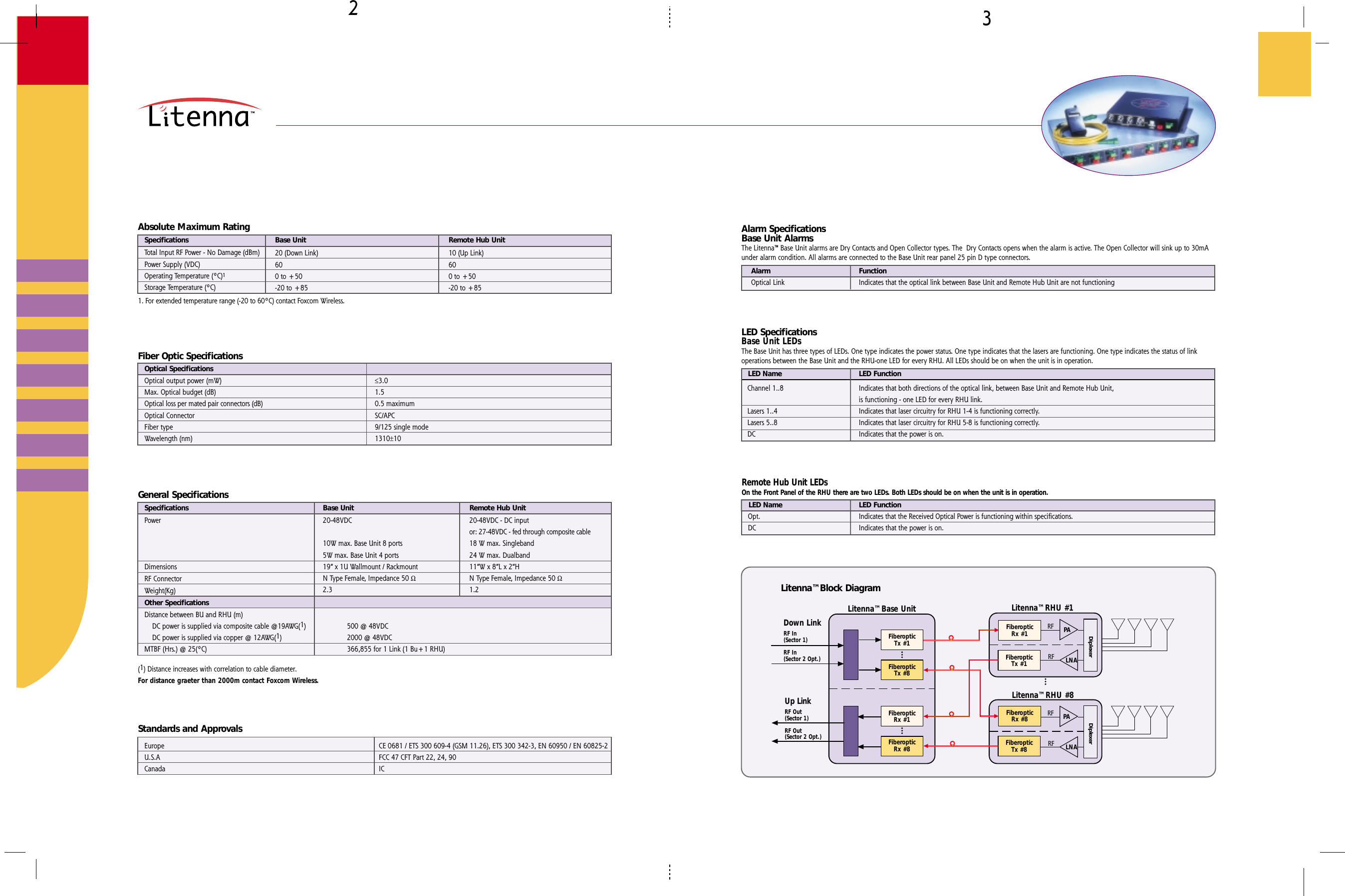
≤≥Alarm SpecificationsBase Unit AlarmsThe Litenna™ Base Unit alarms are Dry Contacts and Open Collector types. The  Dry Contacts opens when the alarm is active. The Open Collector will sink up to 30mAunder alarm condition. All alarms are connected to the Base Unit rear panel 25 pin D type connectors.AlarmOptical LinkFunctionIndicates that the optical link between Base Unit and Remote Hub Unit are not functioningLED SpecificationsBase Unit LEDsThe Base Unit has three types of LEDs. One type indicates the power status. One type indicates that the lasers are functioning. One type indicates the status of linkoperations between the Base Unit and the RHU-one LED for every RHU. All LEDs should be on when the unit is in operation.LED NameChannel 1..8Lasers 1..4Lasers 5..8DCLED FunctionIndicates that both directions of the optical link, between Base Unit and Remote Hub Unit,is functioning - one LED for every RHU link.Indicates that laser circuitry for RHU 1-4 is functioning correctly.Indicates that laser circuitry for RHU 5-8 is functioning correctly.Indicates that the power is on.Remote Hub Unit LEDsOn the Front Panel of the RHU there are two LEDs. Both LEDs should be on when the unit is in operation.LED Name LED FunctionIndicates that the Received Optical Power is functioning within specifications.Indicates that the power is on.Opt.DCLitenna™ Base UnitFiberopticTx #1FiberopticTx #8FiberopticRx #1FiberopticRx #8Down LinkUp LinkRF Out(Sector 1)RF Out(Sector 2 Opt.)RF In(Sector 1)RF In(Sector 2 Opt.)Litenna™ Block DiagramLitenna™ RHU #8FiberopticRx #8FiberopticTx #8PALNADiplexerRFRFLitenna™ RHU #1FiberopticRx #1FiberopticTx #1PALNADiplexerRFRFAbsolute Maximum RatingSpecificationsTotal Input RF Power - No Damage (dBm)Power Supply (VDC)Operating Temperature (ºC)1Storage Temperature (ºC)Base Unit Remote Hub Unit1. For extended temperature range (-20 to 60ºC) contact Foxcom Wireless.20 (Down Link)600 to +50-20 to +8510 (Up Link)600 to +50-20 to +85Fiber Optic Specifications≤3.01.50.5 maximumSC/APC9/125 single mode1310±10Optical SpecificationsOptical output power (mW)Max. Optical budget (dB)Optical loss per mated pair connectors (dB)Optical ConnectorFiber typeWavelength (nm)(1) Distance increases with correlation to cable diameter.For distance graeter than 2000m contact Foxcom Wireless.General SpecificationsSpecifications Base Unit Remote Hub Unit20-48VDC - DC inputor: 27-48VDC - fed through composite cable18 W max. Singleband24 W max. Dualband11”W x 8”L x 2”HN Type Female, Impedance 50 Ω1.2PowerDimensionsRF ConnectorWeight(Kg)Other SpecificationsDistance between BU and RHU (m)    DC power is supplied via composite cable @19AWG(1)    DC power is supplied via copper @ 12AWG(1)MTBF (Hrs.) @ 25(ºC)20-48VDC10W max. Base Unit 8 ports5W max. Base Unit 4 ports19” x 1U Wallmount / RackmountN Type Female, Impedance 50 Ω2.3500 @ 48VDC2000 @ 48VDC366,855 for 1 Link (1 Bu+1 RHU)Standards and ApprovalsEuropeU.S.ACanadaCE 0681 / ETS 300 609-4 (GSM 11.26), ETS 300 342-3, EN 60950 / EN 60825-2FCC 47 CFT Part 22, 24, 90IC
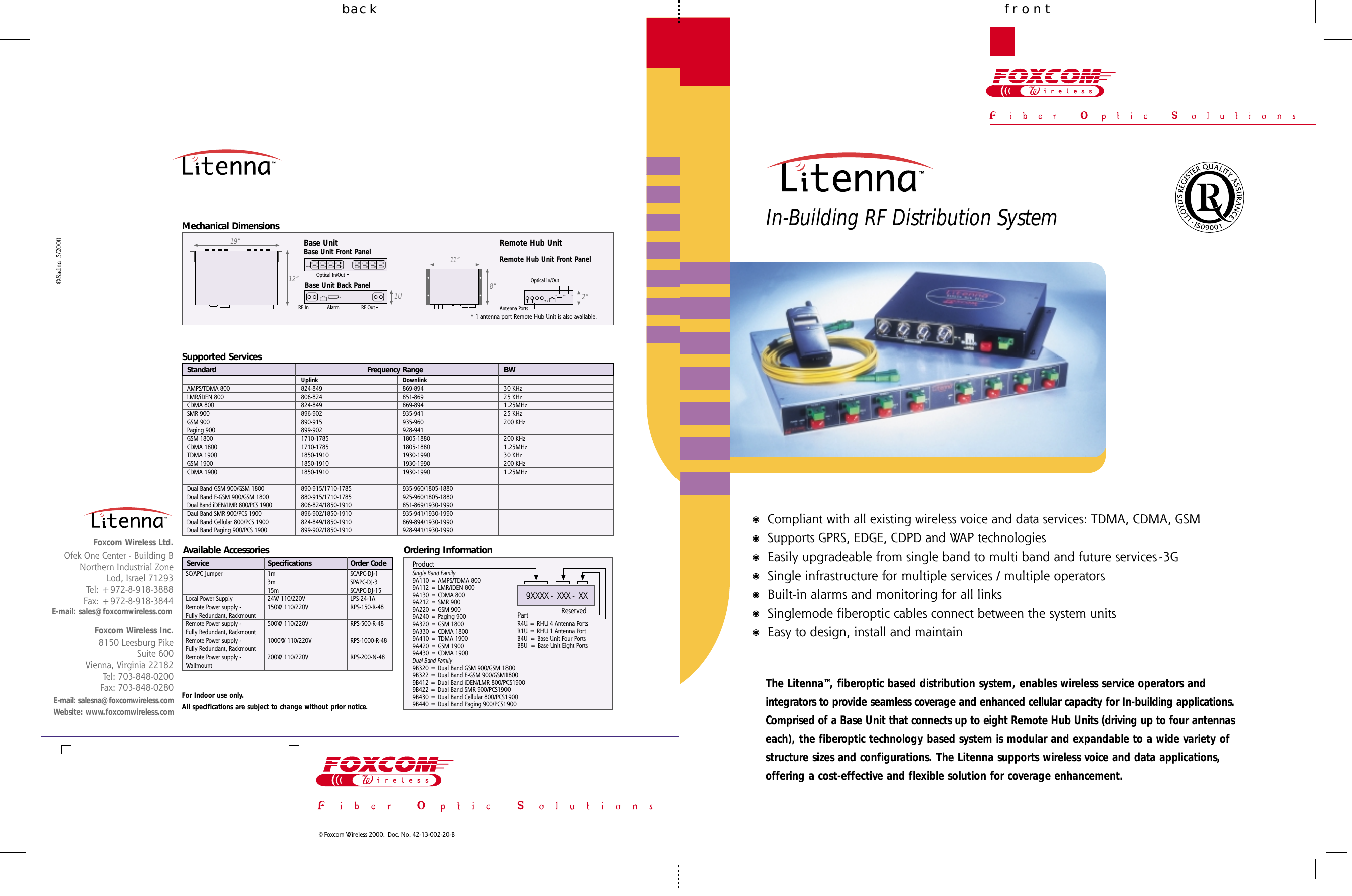
frontbackIn-Building RF Distribution System©Sadna  5/2000© Foxcom Wireless 2000.  Doc. No. 42-13-002-20-BE-mail: salesna@foxcomwireless.comWebsite: www.foxcomwireless.com8150 Leesburg PikeSuite 600Vienna, Virginia 22182Tel: 703-848-0200Fax: 703-848-0280Foxcom Wireless Inc.Ofek One Center - Building BNorthern Industrial ZoneLod, Israel 71293Tel: +972-8-918-3888Fax: +972-8-918-3844Foxcom Wireless Ltd.Frequency RangeAMPS/TDMA 800LMR/iDEN 800CDMA 800SMR 900GSM 900Paging 900GSM 1800CDMA 1800TDMA 1900GSM 1900CDMA 1900Dual Band GSM 900/GSM 1800Dual Band E-GSM 900/GSM 1800Dual Band iDEN/LMR 800/PCS 1900Daul Band SMR 900/PCS 1900Dual Band Cellular 800/PCS 1900Dual Band Paging 900/PCS 1900Uplink824-849806-824824-849896-902890-915899-9021710-17851710-17851850-19101850-19101850-1910890-915/1710-1785880-915/1710-1785806-824/1850-1910896-902/1850-1910824-849/1850-1910899-902/1850-1910Downlink869-894851-869869-894935-941935-960928-9411805-18801805-18801930-19901930-19901930-1990935-960/1805-1880925-960/1805-1880851-869/1930-1990935-941/1930-1990869-894/1930-1990928-941/1930-1990SpecificationsSC/APC JumperLocal Power SupplyRemote Power supply -Fully Redundant, RackmountRemote Power supply -Fully Redundant, RackmountRemote Power supply -Fully Redundant, RackmountRemote Power supply -Wallmount1m3m15m24W 110/220V150W 110/220V500W 110/220V1000W 110/220V200W 110/220VSCAPC-DJ-1SPAPC-DJ-3SCAPC-DJ-15LPS-24-1ARPS-150-R-48RPS-500-R-48RPS-1000-R-48RPS-200-N-48Order CodeBW30 KHz25 KHz1.25MHz25 KHz200 KHz200 KHz1.25MHz30 KHz200 KHz1.25MHzOrdering InformationProductSingle Band Family9A110 = AMPS/TDMA 8009A112 = LMR/iDEN 8009A130 = CDMA 8009A212 = SMR 9009A220 = GSM 9009A240 = Paging 9009A320 = GSM 18009A330 = CDMA 18009A410 = TDMA 19009A420 = GSM 19009A430 = CDMA 1900Dual Band Family9B320 = Dual Band GSM 900/GSM 18009B322 = Dual Band E-GSM 900/GSM18009B412 = Dual Band iDEN/LMR 800/PCS19009B422 = Dual Band SMR 900/PCS19009B430 = Dual Band Cellular 800/PCS19009B440 = Dual Band Paging 900/PCS1900ReservedPartR4U = RHU 4 Antenna PortsR1U = RHU 1 Antenna PortB4U = Base Unit Four PortsB8U  = Base Unit Eight Ports9XXXX -  XXX -  XXSupported ServicesAvailable AccessoriesE-mail: sales@foxcomwireless.comFor Indoor use only.All specifications are subject to change without prior notice.The Litenna™, fiberoptic based distribution system, enables wireless service operators andintegrators to provide seamless coverage and enhanced cellular capacity for In-building applications.Comprised of a Base Unit that connects up to eight Remote Hub Units (driving up to four antennaseach), the fiberoptic technology based system is modular and expandable to a wide variety ofstructure sizes and configurations. The Litenna supports wireless voice and data applications,offering a cost-effective and flexible solution for coverage enhancement.Compliant with all existing wireless voice and data services: TDMA, CDMA, GSMSupports GPRS, EDGE, CDPD and WAP technologiesEasily upgradeable from single band to multi band and future services -3GSingle infrastructure for multiple services / multiple operatorsBuilt-in alarms and monitoring for all linksSinglemode fiberoptic cables connect between the system unitsEasy to design, install and maintainStandardServiceMechanical DimensionsRemote Hub Unit19”12”1UBase UnitBase Unit Front PanelBase Unit Back Panel11”8”Remote Hub Unit Front PanelRF In RF OutAlarmOptical In/OutOptical In/OutAntenna Ports2”* 1 antenna port Remote Hub Unit is also available.
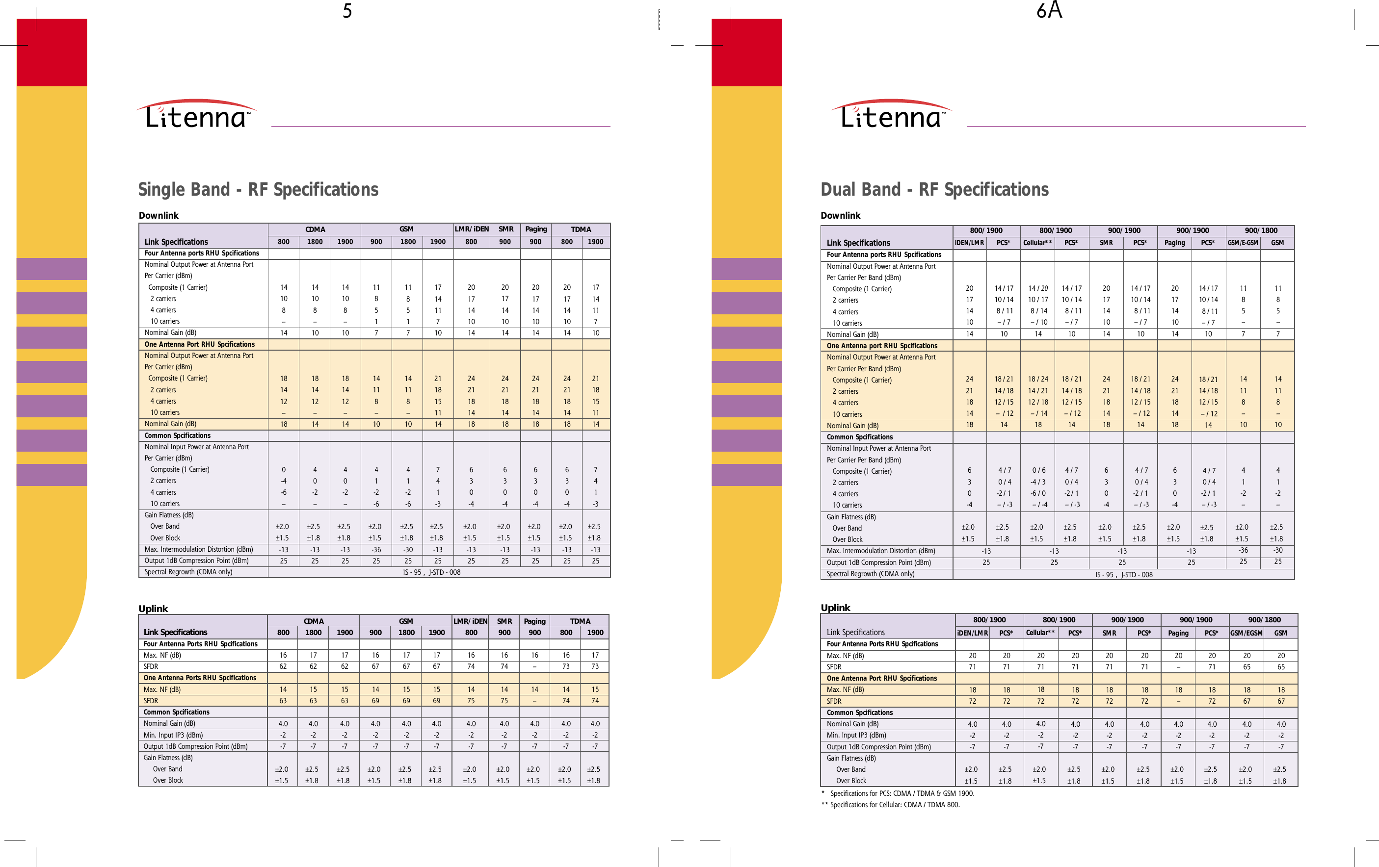
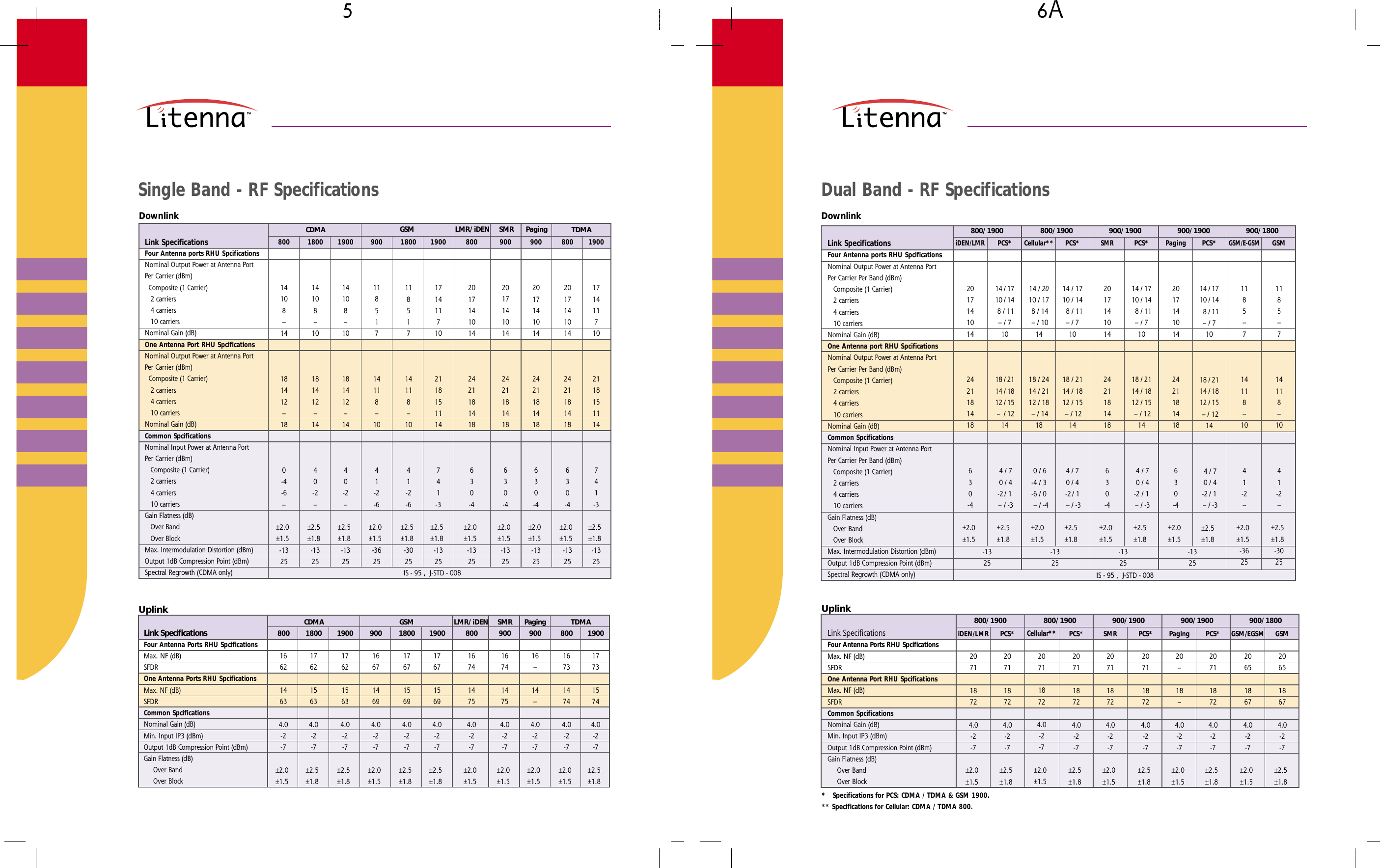
µ ∂ADual Band - RF SpecificationsSingle Band - RF Specifications*   Specifications for PCS: CDMA / TDMA & GSM 1900.** Specifications for Cellular: CDMA / TDMA 800.800/1900 900/1900 900/1900 900/1800UplinkLink Specifications800/1900GSM206518674.0-2-7±2.5±1.8Paging20–18–4.0-2-7±2.0±1.5PCS*207118724.0-2-7±2.5±1.8SMR207118724.0-2-7±2.0±1.5PCS*207118724.0-2-7±2.5±1.8Cellular**207118724.0-2-7±2.0±1.5PCS*207118724.0-2-7±2.5±1.8iDEN/LMR207118724.0-2-7±2.0±1.5PCS*207118724.0-2-7±2.5±1.8GSM/EGSM206518674.0-2-7±2.0±1.5Four Antenna Ports RHU SpcificationsMax. NF (dB)SFDROne Antenna Port RHU SpcificationsMax. NF (dB)SFDRCommon SpcificationsNominal Gain (dB)Min. Input IP3 (dBm)Output 1dB Compression Point (dBm)Gain Flatness (dB)     Over Band     Over BlockUplinkFour Antenna Ports RHU SpcificationsMax. NF (dB)SFDROne Antenna Ports RHU SpcificationsMax. NF (dB)SFDRCommon SpcificationsNominal Gain (dB)Min. Input IP3 (dBm)Output 1dB Compression Point (dBm)Gain Flatness (dB)     Over Band     Over Block800166214634.0-2-7±2.0±1.5Link Specifications CDMA GSM Paging1800176215634.0-2-7±2.5±1.81900176215634.0-2-7±2.5±1.8900166714694.0-2-7±2.0±1.51800176715694.0-2-7±2.5±1.81900176715694.0-2-7±2.5±1.8TDMA90016–14–4.0-2-7±2.0±1.5800167314744.0-2-7±2.0±1.51900177315744.0-2-7±2.5±1.8LMR/iDEN SMR800167414754.0-2-7±2.0±1.5900167414754.0-2-7±2.0±1.5800/1900 900/1900 900/1900 900/1800-1325-1325-1325-1325DownlinkFour Antenna ports RHU SpcificationsNominal Output Power at Antenna PortPer Carrier Per Band (dBm)   Composite (1 Carrier)   2 carriers   4 carriers   10 carriersNominal Gain (dB)One Antenna port RHU SpcificationsNominal Output Power at Antenna PortPer Carrier Per Band (dBm)   Composite (1 Carrier)   2 carriers   4 carriers   10 carriersNominal Gain (dB)Common SpcificationsNominal Input Power at Antenna PortPer Carrier Per Band (dBm)   Composite (1 Carrier)   2 carriers   4 carriers   10 carriersGain Flatness (dB)   Over Band   Over BlockMax. Intermodulation Distortion (dBm)Output 1dB Compression Point (dBm)Spectral Regrowth (CDMA only)Link Specifications800/1900GSM1185–714118–1041-2–±2.5±1.8-3025Paging20171410142421181418630-4±2.0±1.5PCS*14 / 1710 / 14  8 / 11– / 71018 / 2114 / 1812 / 15 – / 1214 4 / 7 0 / 4-2 / 1 – / -3±2.5±1.8SMR20171410142421181418630-4±2.0±1.5PCS*14 / 1710 / 14  8 / 11– / 71018 / 2114 / 1812 / 15 – / 12144 / 70 / 4-2 /  1 – / -3±2.5±1.8Cellular**14 / 2010 / 17 8 / 14 – / 101418 / 2414 / 2112 / 18 – / 1418 0 / 6-4 / 3-6 / 0  – / -4±2.0±1.5PCS*14 / 1710 / 14 8 / 11– / 71018 / 2114 / 1812 / 15 –  / 1214 4 / 7 0 / 4-2 / 1 –  / -3±2.5±1.8iDEN/LMR20171410142421181418630-4±2.0±1.5PCS*14 / 1710 / 14  8 / 11– / 71018 / 2114 / 1812 / 15 – / 1214 4 / 7 0 / 4-2  /  1 – / -3±2.5±1.8GSM/E-GSM1185–714118–1041-2–±2.0±1.5-3625IS - 95 ,  J-STD - 008DownlinkLink SpecificationsCDMA GSM LMR/iDEN TDMA19001714117102118151114741-3±2.5±1.8-132580020171410142421181418630-4±2.0±1.5-132580020171410142421181418630-4±2.0±1.5-132519001714117102118151114741-3±2.5±1.8-1325180011851714118–1041-2-6±2.5±1.8-302590011851714118–1041-2-6±2.0±1.5-3625190014108–10181412–1440-2–±2.5±1.8-1325180014108–10181412–1440-2–±2.5±1.8-132580014108–14181412–180-4-6–±2.0±1.5-1325SMR90020171410142421181418630-4±2.0±1.5-1325Paging90020171410142421181418630-4±2.0±1.5-1325IS - 95 ,  J-STD - 008Four Antenna ports RHU SpcificationsNominal Output Power at Antenna PortPer Carrier (dBm)  Composite (1 Carrier)   2 carriers   4 carriers   10 carriersNominal Gain (dB)One Antenna Port RHU SpcificationsNominal Output Power at Antenna PortPer Carrier (dBm)  Composite (1 Carrier)   2 carriers   4 carriers   10 carriersNominal Gain (dB)Common SpcificationsNominal Input Power at Antenna PortPer Carrier (dBm)   Composite (1 Carrier)   2 carriers   4 carriers   10 carriersGain Flatness (dB)   Over Band   Over BlockMax. Intermodulation Distortion (dBm)Output 1dB Compression Point (dBm)Spectral Regrowth (CDMA only)

Navigation menu