Corning Optical Communication MA1000 Mobile Telephone In-Building Distribution System User Manual 2 MobileAccess 1000 a CC8FD
Corning Optical Communication Wireless Mobile Telephone In-Building Distribution System 2 MobileAccess 1000 a CC8FD
User manual
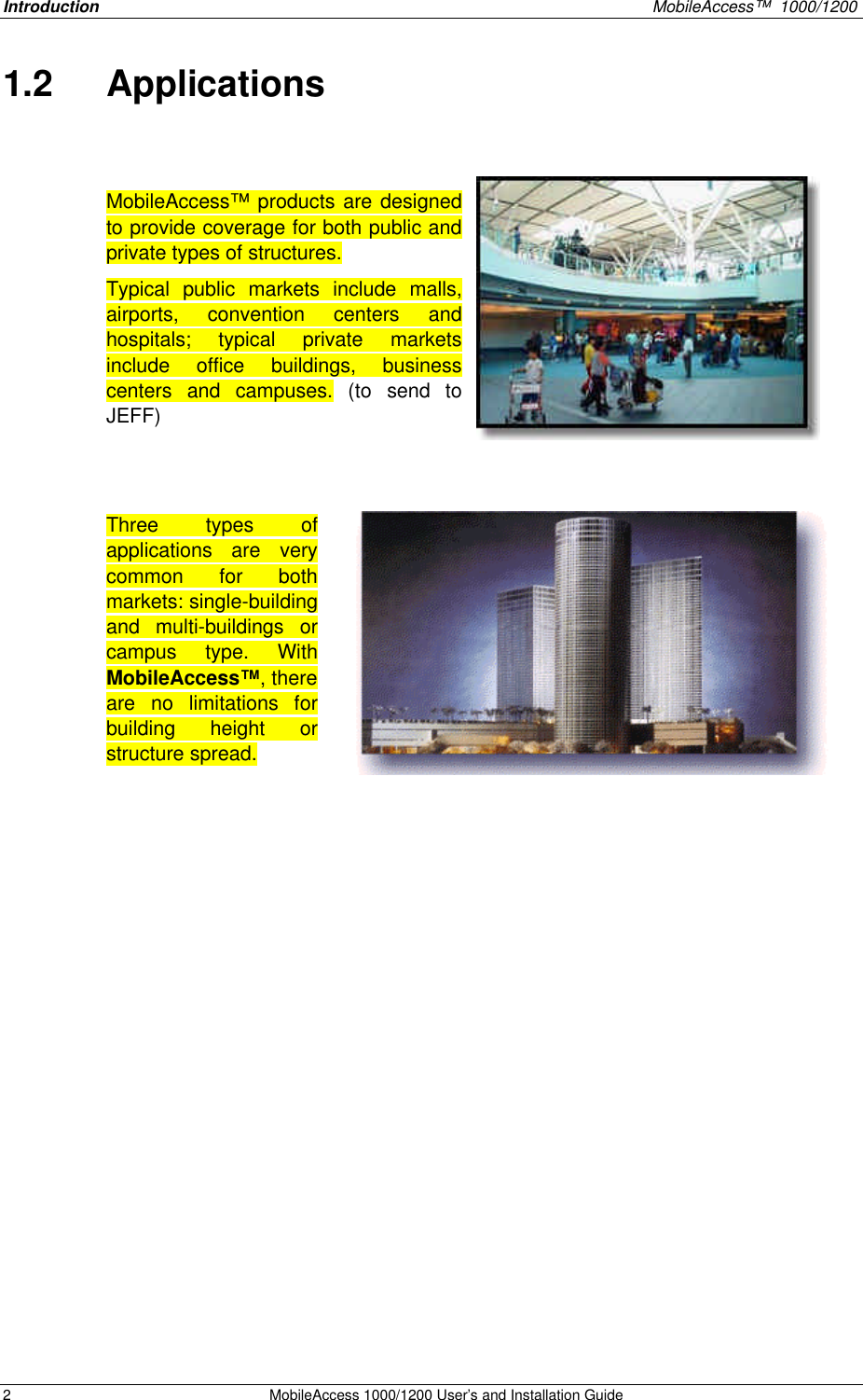
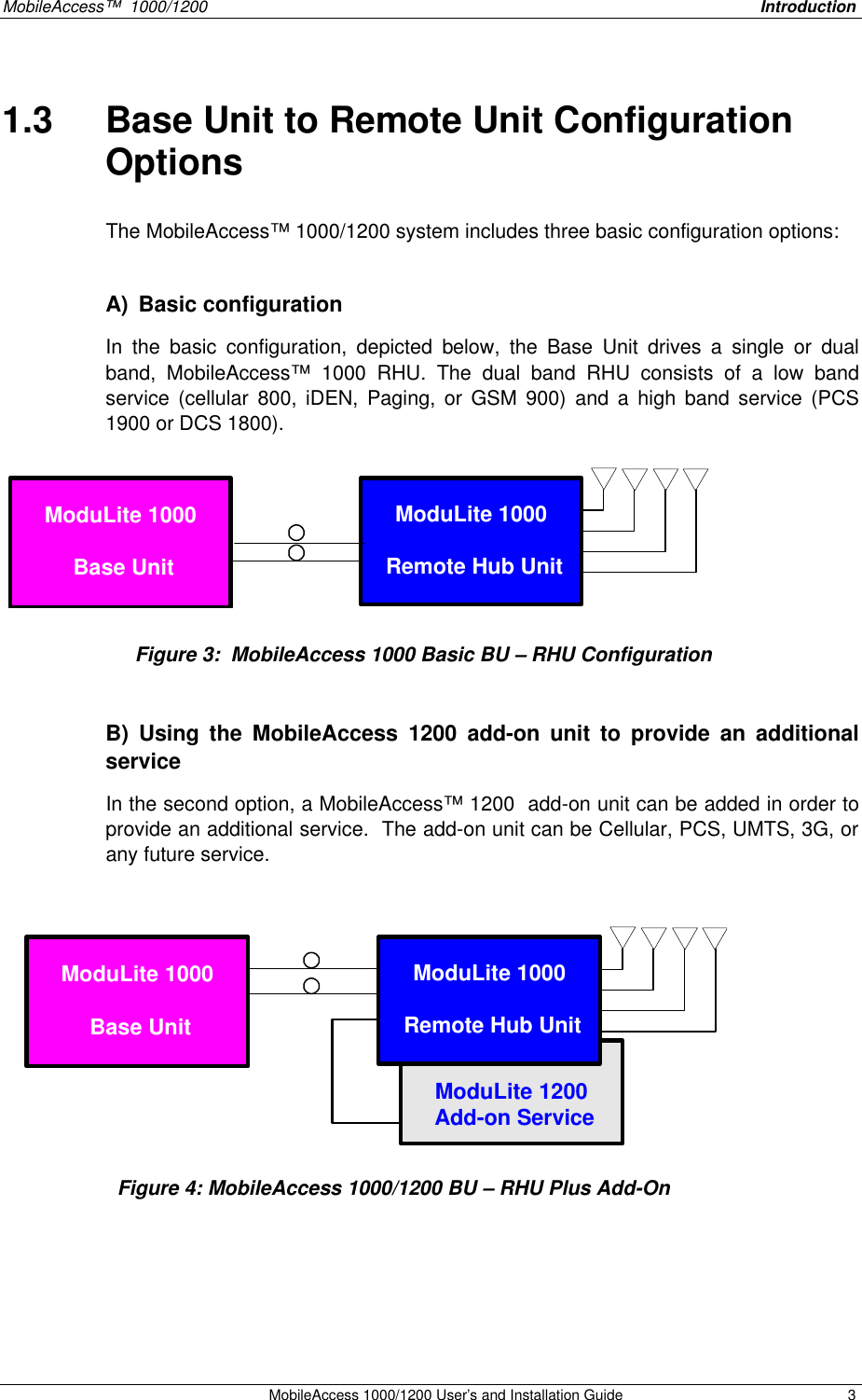
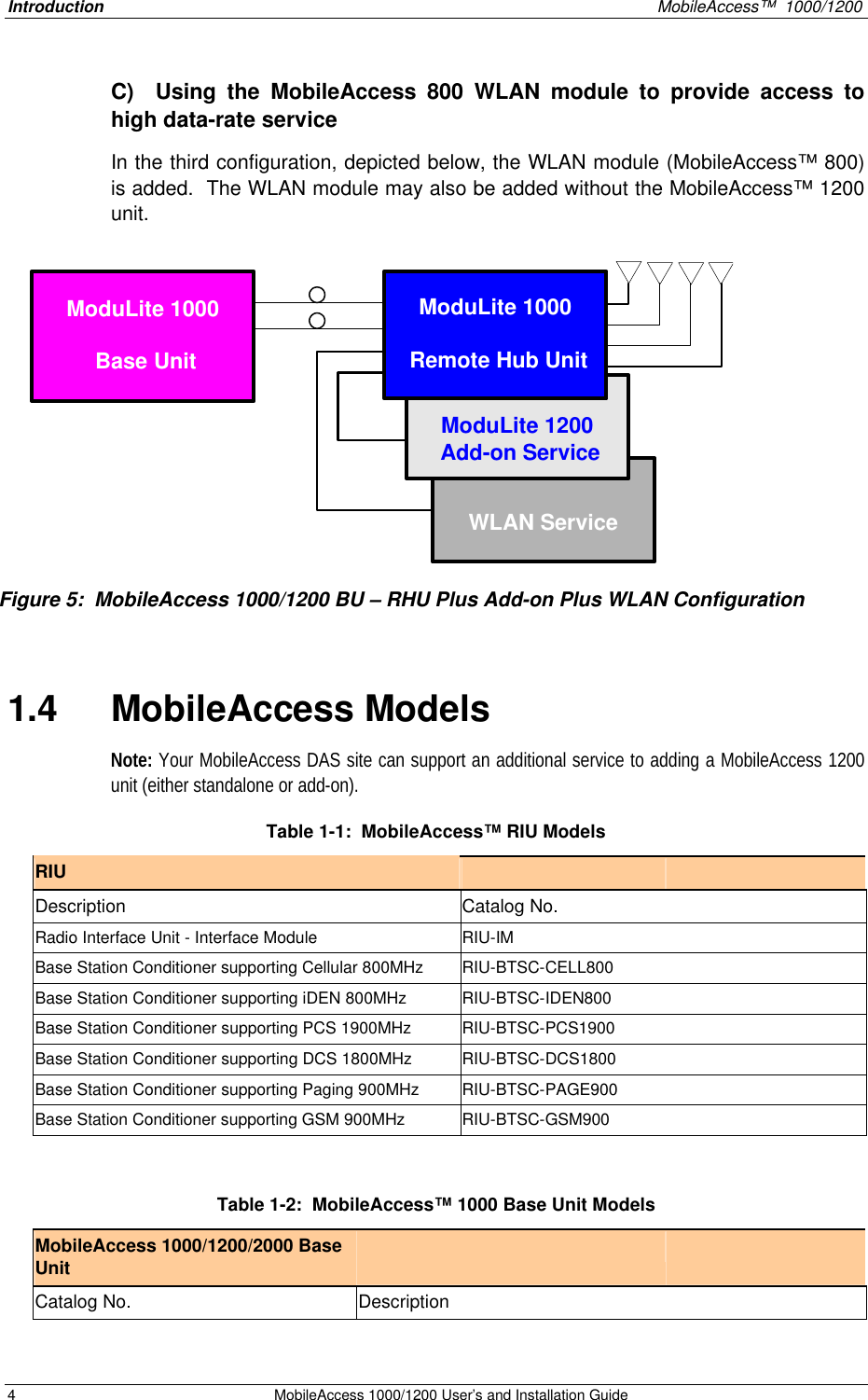
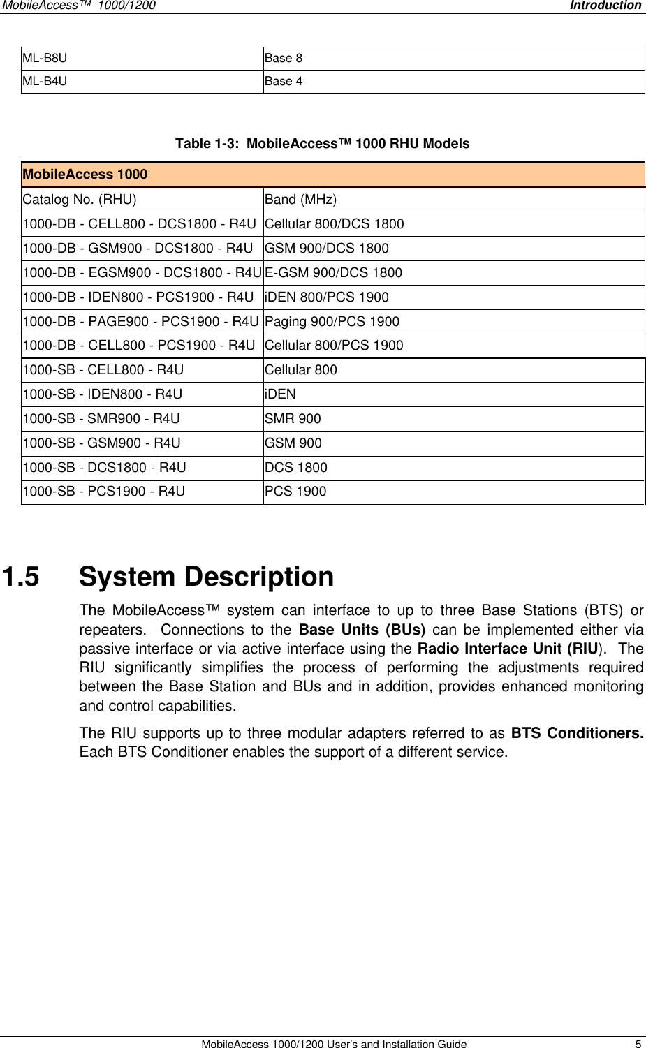
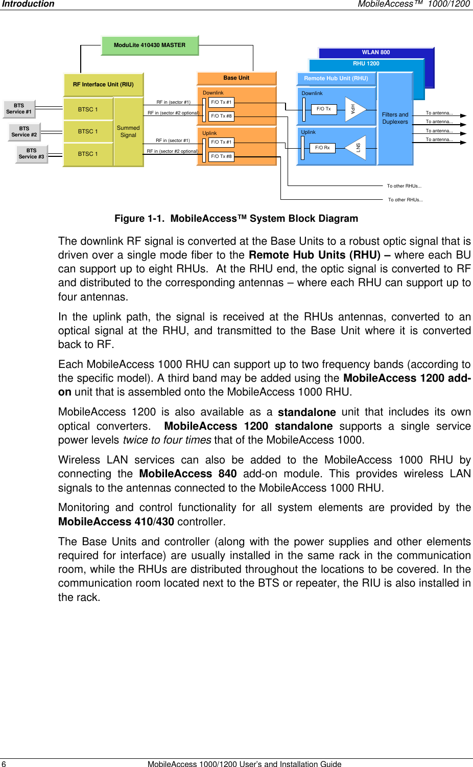


![MobileAccess 1000/1200 User’s and Installation Guide 31 Appendix A. Frequently Asked Questions 1. What are the BU and the RHU, and for what are they used for? The MobileAccess™ system consists of two modules: Base Unit and Remote Hub Unit. The Base Unit interfaces between the microcell or base station and the Remote Hub Unit (RHU). The interface is via either a composite cable or fiber optic cable. In this description, on the downlink path, the Base Unit converts incoming RF signals to optical signals, transmitting these signals over fiber optic cable to the RHU. The RHU converts the optical signal back to RF. The RHU drives the four connected antennas. On the uplink path, the RHU combines and converts incoming RF signals from the four antennas into optical signals, transmitting these signals back to the Base Unit. The Base Unit converts the signals back into RF signals. 2. How does the BU connect to the RHU, and which fibers and connectors are required? The BU connects to the RHU via fiber optic cable. The system uses 2 fibers for each RHU connection, one fiber for the uplink and one fiber for the downlink. The MobileAccess™ system requires singlemode fibers and SC/APC connectors. 3. How many RHU’s and antennas are required for each floor in a building? Determine the number of RHU’s and antennas per floor depends on the building size and configuration. Each RHU can support up to four antennas. It is possible to connect several BUs together in one installation, increasing the amount of available RHU’s. With one BU able to support up to eight RHU’s, this translates to up to 32 antennas. 4. Is the RHU and BU power supply AC or DC? and what is the voltage level? The power needs of the BU and RHU are supplied by DC power. The voltage level is 18V-48V. MobileAccess offers a power supply for the BU as well as the RHU. The power supply options are a Remote-located power supply, or a Local power supply. The Remote-located power supply is located near the BU. This power supply drives the BU and the RHU’s. To provide power, the BU is connected to the power supply via electrical cables. For power to the RHU, a composite cable can be used. [A composite cable contains two fiber cables and two copper electrical wires in the same jacket] The Local power supply provides power to the BU and to the RHU separately. A Local power supply is co-located with each BU and RHU, not requiring long electrical cable runs. 5. Can the RHU be used in outdoor applications? Currently, the RHU can be used only for indoor applications. The RHU can be upgraded for outdoor applications. 6. What type of antennas can be used? All antennas types (appropriate to the cellular standard used) can be used for the MobileAccess™ system, including leaky coax. 7. Does the RHU require a dedicated power supply or can it be powered by remote? The RHU can be supplied with a local power supply, or by a remote powering DC cable over fiber optic cables (composite cable). 8. Can the MobileAccess™ Base Unit be connected to the BTS/Microcell/BDA/off-air repeater? The MobileAccess™ BU can be connected to the following: BTS, Microcell, Off-air Repeater (with virtually no modifications). 9. Does the MobileAccess™ require any special tuning or adjustments during the installation? The MobileAccess™ doesn’t required any special tuning or adjustments during the installation. 10. Does the MobileAccess™ support multi services, like GSM Dual band? The MobileAccess™ system is upgradable to support multi services over the same fiber cable, like GSM Dual-Band (900/1800). The system will also be available as a field modular system for UMTS (3G). 11. What are advantages of the MobileAccess™ compared to a coax solution? The MobileAccess™ advantages over coax are: Low cost per antenna, easy to install and maintain, flexible placement, easy to configuration, and future proof.](https://usermanual.wiki/Corning-Optical-Communication/MA1000/User-Guide-380008-Page-47.png)