Corning Optical Communication MA1000 Mobile Telephone In-Building Distribution System User Manual 2 MobileAccess 1000 a CC8FD
Corning Optical Communication Wireless Mobile Telephone In-Building Distribution System 2 MobileAccess 1000 a CC8FD
User manual

MobileAccess 1000/1200 User’s and Installation Guide
MobileAccess™ 1000/1200
Installation and Configuration Guide
Version 1.0
May 2003

Preface MobileAccess™ 1000/1200
II MobileAccess 1000/1200 User’s and Installation Guide
Copyright © 2003 MobileAccess.
All rights reserved. Printed in Israel.
© 2003 by MobileAccess
This document contains confidential and proprietary information of MobileAccess
and may not be copied, transmitted, stored in a retrieval system or reproduced in
any format or media, in whole or in part, without the prior written consent of
MobileAccess. Information contained in this document supersedes any previous
manuals, guides, specifications, data sheets or other information that may have
been provided or made available to the user. This document is provided for
informational purposes only, and MobileAccess does not warrant or guarantee the
accuracy, adequacy, quality, validity, completeness or suitability for any purpose of
the information contained in this document. MobileAccess reserves the right to make
updates, improvements and enhancements to this document and the products to
which it relates at any time without prior notice to the user. MOBILEACCESS
MAKES NO WARRANTIES, EXPRESS OR IMPLIED, INCLUDING, WITHOUT
LIMITATION, THOSE OF MERCHANTABILITY AND FITNESS FOR A
PARTICULAR PURPOSE, WITH RESPECT TO THIS DOCUMENT OR ANY
INFORMATION CONTAINED HEREIN.
TRADEMARK ACKNOWLEDGEMENT
MobileAccessTM, RF2MobileAccess, and MobileAccessTM are registered trademarks
of MobileAccess. This document contains other trademarks, trade names and
service marks of MobileAccess and other organizations, all of which are the property
of their respective owners.
MobileAccess Ltd. Vienna, Virginia Tel: +1-703-848-0200
MobileAccess Ltd. Lod, Israel Tel: +972-8-9183888
http://www.mobileaccess.com
Email: sales@mobileaccess.com

MobileAccess™ 1000/1200 Preface
MobileAccess 1000/1200 User’s and Installation Guide III
POLICY FOR WARRANTEE AND REPAIR
MobileAccess tests and inspects all its products to verify their quality and reliability.
MobileAccess uses every reasonable precaution to ensure that each unit meets their
declared specifications before shipment. Customers should advise their incoming inspection,
assembly, and test personnel about the precautions required in handling and testing our
products. Many of these precautions can be found in this manual.
The products are covered by the following warranties:
General Warranty
MobileAccess warrants to the original purchaser all standard products sold by MobileAccess
to be free of defects in material and workmanship for one (1) year from date of shipment from
MobileAccess. During the warranty period, MobileAccess will repair or replace any product
that MobileAccess proves to be defective. This warranty does not apply to any product that
has been subject to alteration, abuse, improper installation or application, accident, electrical
or environmental over-stress, negligence in use, storage, transportation or handling.
Specific Product Warranty Instructions
All MobileAccess products are warranted against defects in workmanship, materials and
construction, and to no further extent. Any claim for repair or replacement of units found to be
defective on incoming inspection by a customer must be made within 30 days of receipt of
shipment, or within 30 days of discovery of a defect within the warranty period.
This warranty is the only warranty made by MobileAccess and is in lieu of all other
warranties, expressed or implied. MobileAccess sales agents or representatives are not
authorized to make commitments on warranty returns.
RETURNS
In the event that it is necessary to return any product against above warranty, the
following procedure shall be followed:
1. Return authorization is to be received from MobileAccess prior to returning any
unit. Advise MobileAccess of the model, serial number, and discrepancy. The
unit may then be forwarded to MobileAccess, transportation prepaid. Devices
returned collect or without authorization may not be accepted.
2. Prior to repair, MobileAccess will advise the customer of our test results and any
charges for repairing customer-caused problems or out-of-warranty conditions
etc.
3. Repaired products are warranted for the balance of the original warranty period,
or at least 90 days from date of shipment.

Preface MobileAccess™ 1000/1200
IV MobileAccess 1000/1200 User’s and Installation Guide
LIMITATIONS OF LIABILITIES
MobileAccess's liability on any claim, of any kind, including negligence for any loss or
damage arising from, connected with, or resulting from the purchase order, contract,
quotation, or from the performance or breach thereof, or from the design, manufacture, sale,
delivery, installation, inspection, operation or use of any equipment covered by or furnished
under this contact, shall in no case exceed the purchase price of the device which gives rise
to the claim.
EXCEPT AS EXPRESSLY PROVIDED HEREIN, MOBILEACCESS MAKES NO WARRANTY, EXPRESSED OR
IMPLIED, WITH RESPECT TO ANY GOODS, PARTS AND SERVICES PROVIDED IN CONNECTION WITH THIS
AGREEMENT INCLUDING, BUT NOT LIMITED TO, THE IMPLIED WARRANTIES OF MERCHANTABILITY AND
FITNESS FOR A PARTICULAR PURPOSE. MOBILEACCESS SHALL NOT BE LIABLE FOR ANY OTHER
DAMAGE INCLUDING, BUT NOT LIMITED TO, INDIRECT, SPECIAL OR CONSEQUENTIAL DAMAGES ARISING
OUT OF OR IN CONNECTION WITH FURNISHING OF GOODS, PARTS AND SERVICE HEREUNDER, OR THE
PERFORMANCE, USE OF, OR INABILITY TO USE THE GOODS, PARTS AND SERVICE.
REPORTING DEFECTS
The units were inspected before shipment and found to be free of mechanical and electrical
defects.
Examine the units for any damage that may have been caused in transit. If damage is
discovered, file a claim with the freight carrier immediately. Notify MobileAccess as soon as
possible.
NOTE: Keep all packing material until you have completed the inspection
WARNING: To comply with FCC RF exposure compliance requirements, antennas used for
this product must be fixed mounted on indoor permanent structures, providing a separation
distance of at least 20 cm from all persons during normal operation.
WARNING: Antenna gain should not exceed 10dB.
WARNING: Each individual antenna used for this transmitter must be installed to provide a
minimum separation distance of 20 cm or more from all persons and must not be co-located
with any other antenna for meeting RF exposure requirements.

MobileAccess™ 1000/1200 Preface
MobileAccess 1000/1200 User’s and Installation Guide V
WARNING: The MobileAccessTM system uses an optical laser for transmitting voice and
data. The laser unit has the following output characteristics:
- Optical output power (mW): ≤3.0
- Wavelength (nM): 1310 ± 10
WARNING: Applying power to the MobileAccess™ creates a laser energy source operating
in class I as defined by IEC 60825-1, 21 CFR 1040.10 and 1040.11 except for deviations
pursuant to laser notice no. 50 (July 26, 2001). Use either an infrared viewer, optical power
meter or fluorescent screen for optical output verification.
WARNING: The use of controls or adjustments or performance procedures other than those
specified herein may result in hazardous radiation exposure.
WARNING:
Compliance with RF safety requirements:
MobileAccess™ products have no inherent significant rf radiation.
The Rf level on the down link is very low at the remote hub unit downlink ports. Therefore,
there is no dangerous rf radiation when the antenna is not connected.
The design of the antenna installation needs to be implemented in such a way so as to
ensure rf radiation safety levels and non- environmental pollution during operation.
ATTENTION: To avoid damaging your product, please observe the following:
• Always keep the optical connector covered. Use the fiber optic cable or a
protective cover. Do not allow any dirt and/or foreign material to get on the optical
connector bulkheads.
• The optical fiber jumper cable bend radius is 3 cm. Smaller radii can cause
excessive optical loss and/or fiber breakage.
• For proper system performance only use cables equipped with
SC/APC connectors to connect to the MobileAccess MobileAccesstm system.

Preface MobileAccess™ 1000/1200
VI MobileAccess 1000/1200 User’s and Installation Guide
CERTIFICATION
MobileAccess products have met the approvals of the following certifying organizations:
ISO 9001
For Europe
0681
For US
FCC 47 CFT part 15,22,24,90
FDA-CDRH
UL
For Canada
RSS-118, RSS-119, RSS-133«.
SPECIFICATIONS
Maximum ambient operating temperature: 50° C
Maximum ambient temperature in a rack: 50° C

MobileAccess™ 1000/1200 Preface
MobileAccess 1000/1200 User’s and Installation Guide VII
Preface
This user guide provides all the information necessary to…
User Guide Organization
Chapter 1. Introduction. About MobileAccess 1000/1200 .
Chapter 2.
Chapter 3.
Chapter 4.
Appendix A.

Preface MobileAccess™ 1000/1200
VIII MobileAccess 1000/1200 User’s and Installation Guide
Revision History
The revision history for this document is shown in Table 1-1.
Table 1-1: Revision history
Version Date Description
1.0 April 2003 Initial version.
Terms and definitions
Table 1-2: Terms and Definitions
Term Definition
BSC Base Station Controller
BTS Base Station Transceiver Subsystem

MobileAccess 1000/1200 User’s and Installation Guide
Table of Contents
Chapter 1. Introduction 1
1.1 About MobileAccess 1000/1200™ .........................................................................................................................1
1.2 Applications ...........................................................................................................................................................2
1.3 Base Unit to Remote Unit Configuration Options...................................................................................................3
1.4 MobileAccess Models ............................................................................................................................................4
1.5 System Description................................................................................................................................................5
Chapter 2. Module Description..........................................................................................................................1
2.1 Radio Interface Unit (RIU)......................................................................................................................................1
2.1.1 General.......................................................................................................................................................1
2.1.2 Front and Rear Panel Descriptions.............................................................................................................2
2.2 Base Unit ...............................................................................................................................................................3
2.2.1 General.......................................................................................................................................................3
2.2.2 Base Unit Front and Rear Panels...............................................................................................................4
2.2.3 Remote Hub Unit (RHU).............................................................................................................................6
2.2.3.1 MobileAccess 1000.....................................................................................................................6
2.2.3.2 MobileAccess 1200.....................................................................................................................7
2.2.4 MobileAccess 410/430 Controller...............................................................................................................8
Chapter 3. Installation Procedure ...................................................................................................................10
3.1 General ................................................................................................................................................................11
3.2 About Infrastructure Installation ...........................................................................................................................14
3.3 Power Supply for the MobileAccess™.................................................................................................................15
3.4 Rack Installation ..................................................................................................................................................17
3.5 Connecting Each of the MobileAccess Elements.................................................................................................18
3.5.1 Base Unit Connections.............................................................................................................................18
3.5.2 Base Unit to BTS Side Connections .........................................................................................................19
3.5.2.1 Connections via Passive RF Interface ......................................................................................19
3.5.2.2 Connections via Radio Interface Unit (RIU) ..............................................................................21
3.5.3 Base Unit to RHU connections .................................................................................................................22
3.6 Remote Hub Units (RHUs) 1000..........................................................................................................................23
3.7 RHU 1200............................................................................................................................................................23
3.7.1 Remote Hub Unit 1200 Add-on Unit .........................................................................................................23
3.7.2 Remote Hub Unit 1200 Standalone..........................................................................................................25
3.8 Controller Connections ........................................................................................................................................26
3.9 Power Supply Connections..................................................................................................................................26
Chapter 4. Adjustments Procedure.................................................................................................................27
4.1.1 Auto-detect ...............................................................................................................................................27
4.1.2 Downlink Adjustments ..............................................................................................................................29
4.1.3 Main or Independent Building with RIU Adjustment..................................................................................29
4.1.4 First Band Adjustment ..............................................................................................................................29
4.1.4.1 First Band (any of the bands)....................................................................................................29
4.1.4.2 First band downlink adjustment ................................................................................................30

Preface MobileAccess™ 1000/1200
X MobileAccess 1000/1200 User’s and Installation Guide
Appendix A. Frequently Asked Questions........................................................................................................ 31
Appendix B. : Link Measurements Form......................................................................................................... 33
Appendix C. Fiber Optic Cable Instructions ..................................................................................................... 34
Fiber Optic Cable................................................................................................................................................ 34
Appendix D. Fiber Optic Cable – Terms............................................................................................................ 37
Optical Fiber........................................................................................................................................................ 37
Connecting Fiber Optic Cable............................................................................................................................. 39
Fiber Optic Cable Bending Loss .............................................................................................................. 39
Coupler 39
Appendix E. Optical Test Procedure................................................................................................................. 40
Fiber Optic Cable Test ........................................................................................................................................ 40
MobileAccess System Characteristics ................................................................................................................ 40
Test Equipment................................................................................................................................................... 41
Optical Insertion Loss Measurement Test........................................................................................................... 41
Method #1: Two Point Test...................................................................................................................... 41
Method #2: Single Point Test.............................................................................................................................. 42
Other Test Equipment......................................................................................................................................... 42
Optical Return Loss Measurement Test.............................................................................................................. 43
Measurement Procedure..................................................................................................................................... 43
Results................................................................................................................................................................ 44
Summary............................................................................................................................................................. 44

Nomad Access Confidential & Proprietary - Use Subject to Restrictions 1
Chapter 1. Introduction
1.1 About MobileAccess 1000/1200™
MobileAccess™ 1000/1200 family of products provides seamless coverage for voice
and data wireless services in difficult indoor environments such as those found in
large corporate business buildings, airports, convention centers, hospitals and
university campuses. In these types of locations materials such as steel, concrete
and earth block RF signals; in high-rise buildings the opposite phenomena often
occurs – reception of multiple signals that cause interference.
MobileAccess™ is a hybrid fiber coax modular DAS solution designed to serve
multiple wireless services using a single common cabling infrastructure.
Homogeneous coverage is provided by antennas connected to Remote Hub Units
(RHUs) distributed throughout the coverage area.
The MobileAccess™ infrastructure is protocol-independent and can simultaneously
serve various frequency bands and protocols for voice and data wireless services.
The MobileAccess™ includes built-in alarm and control capabilities that enable
remote monitoring and control of the system elements (including antennas).
Features
• Single cabling and antenna system for all services and frequency bands
• Support for all current and future voice and data wireless services such as
PCS/CELLULAR, TDMA, CDMA, GSM, future 3G protocols, Paging, iDEN
and 802.11 (a,b,g) Wireless LAN
• Upgradeable to include additional services
• Eliminates RF interferences occurring where multiple antenna systems are
used to serve multiple services
• Enables fast deployment for corporate enterprises, property owners and
WSP’s of new services
• Reduces tenant disruption
• Minimal input power to MobileAccess™ (~0dBm) - No need for high power
BTS/RBS, less expenses for the operators.
• Provides both local and remote monitoring and control capabilities
• Software programmable parameters including output power, AGC (on/off and
levels), and system gain
• Real time component setting capabilities for optimal performance (aging,
temperature, optical connectors, etc.,)
• Modular design architecture

Introduction MobileAccess™ 1000/1200
2 MobileAccess 1000/1200 User’s and Installation Guide
1.2 Applications
MobileAccess™ products are designed
to provide coverage for both public and
private types of structures.
Typical public markets include malls,
airports, convention centers and
hospitals; typical private markets
include office buildings, business
centers and campuses. (to send to
JEFF)
Three types of
applications are very
common for both
markets: single-building
and multi-buildings or
campus type. With
MobileAccess™, there
are no limitations for
building height or
structure spread.
MobileAccess™ 1000/1200 Introduction
MobileAccess 1000/1200 User’s and Installation Guide 3
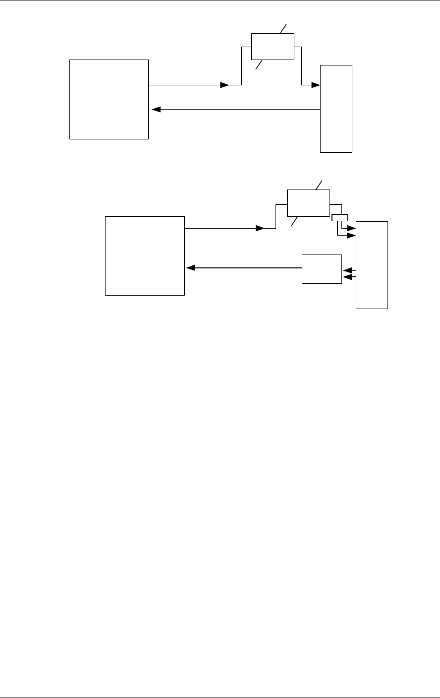
1.3 Base Unit to Remote Unit Configuration
Options
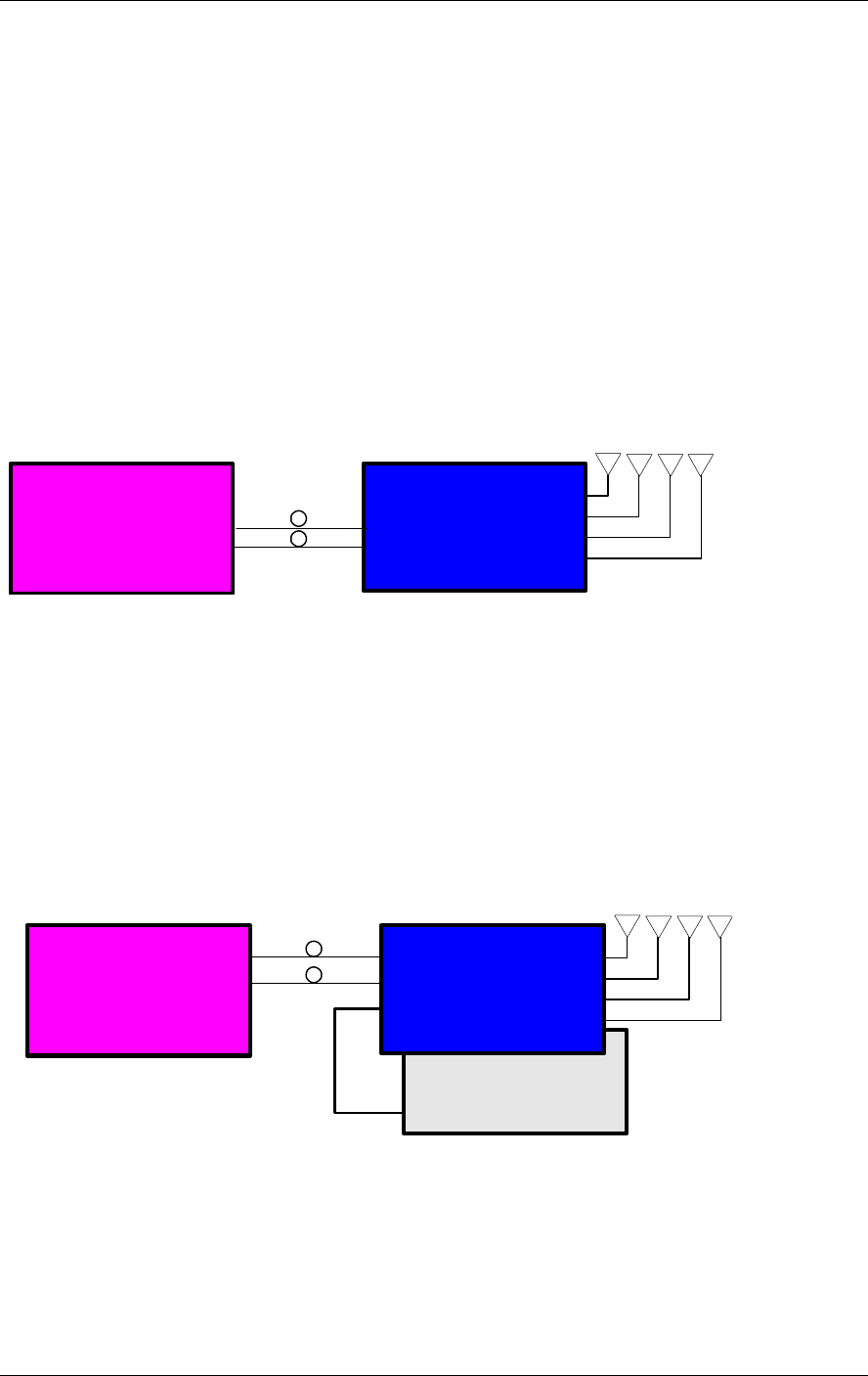
The MobileAccess™ 1000/1200 system includes three basic configuration options:
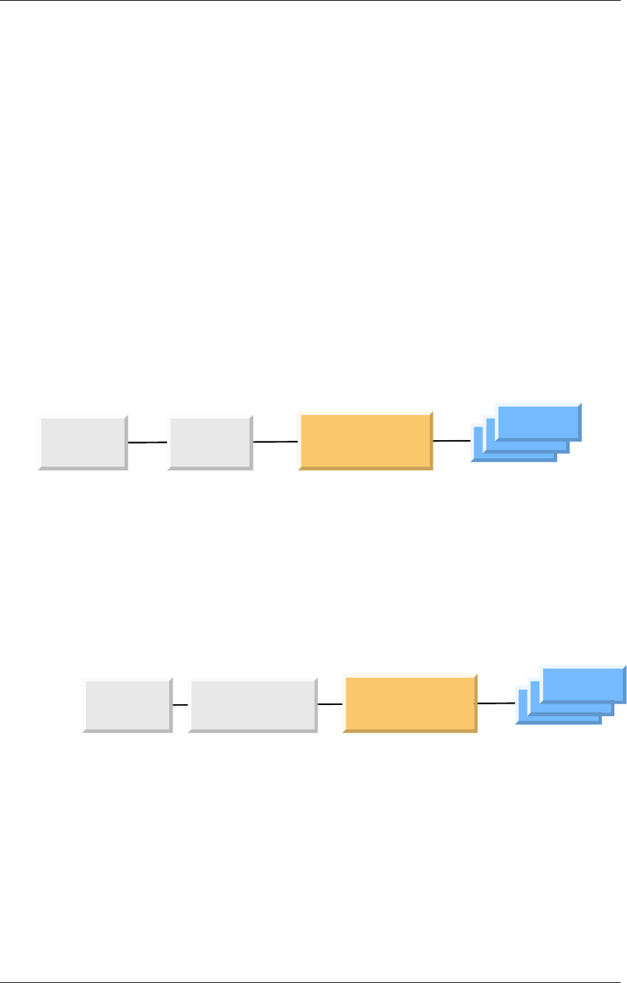
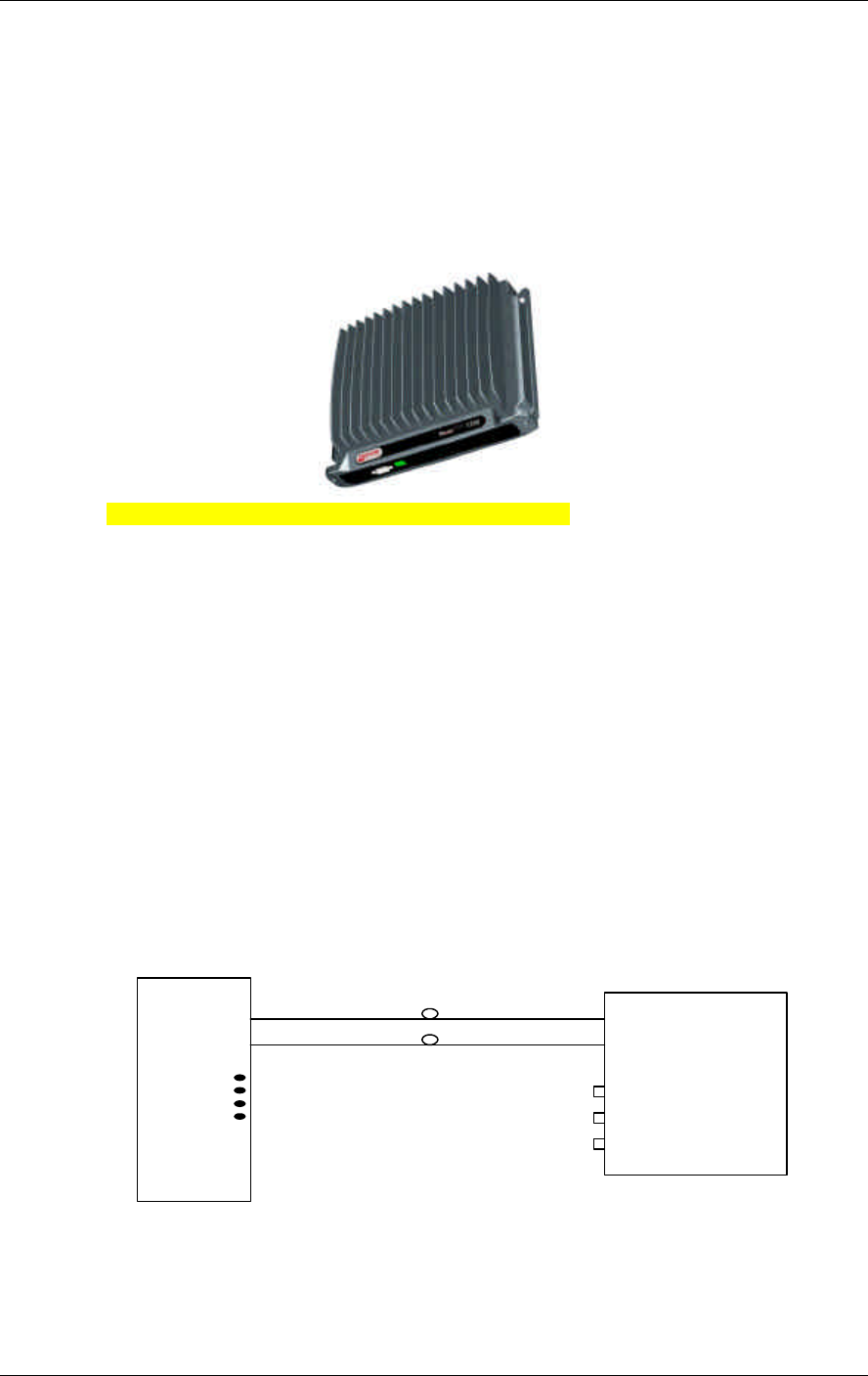
A) Basic configuration
In the basic configuration, depicted below, the Base Unit drives a single or dual
band, MobileAccess™ 1000 RHU. The dual band RHU consists of a low band
service (cellular 800, iDEN, Paging, or GSM 900) and a high band service (PCS
1900 or DCS 1800).
ModuLite 1000
Remote Hub Unit
ModuLite 1000
Base Unit
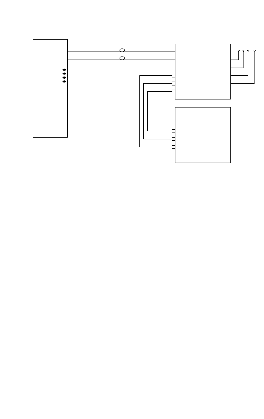
B) Using the MobileAccess 1200 add-on unit to provide an additional
service
In the second option, a MobileAccess™ 1200 add-on unit can be added in order to
provide an additional service. The add-on unit can be Cellular, PCS, UMTS, 3G, or
any future service.
ModuLite 1200
Add-on Service
ModuLite 1000
Remote Hub Unit
ModuLite 1000
Base Unit
Figure 3: MobileAccess 1000 Basic BU – RHU Configuration
Figure 4: MobileAccess 1000/1200 BU – RHU Plus Add-On
Introduction MobileAccess™ 1000/1200
4 MobileAccess 1000/1200 User’s and Installation Guide
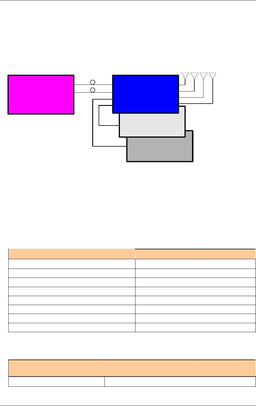
C) Using the MobileAccess 800 WLAN module to provide access to
high data-rate service
In the third configuration, depicted below, the WLAN module (MobileAccess™ 800)
is added. The WLAN module may also be added without the MobileAccess™ 1200
unit.
WLAN Service
ModuLite 1200
Add-on Service
ModuLite 1000
Base Unit
ModuLite 1000
Remote Hub Unit
1.4 MobileAccess Models
Note: Your MobileAccess DAS site can support an additional service to adding a MobileAccess 1200
unit (either standalone or add-on).
Table 1-1: MobileAccess™ RIU Models
RIU
Description Catalog No.
Radio Interface Unit - Interface Module RIU-IM
Base Station Conditioner supporting Cellular 800MHz RIU-BTSC-CELL800
Base Station Conditioner supporting iDEN 800MHz RIU-BTSC-IDEN800
Base Station Conditioner supporting PCS 1900MHz RIU-BTSC-PCS1900
Base Station Conditioner supporting DCS 1800MHz RIU-BTSC-DCS1800
Base Station Conditioner supporting Paging 900MHz RIU-BTSC-PAGE900
Base Station Conditioner supporting GSM 900MHz RIU-BTSC-GSM900
Table 1-2: MobileAccess™ 1000 Base Unit Models
MobileAccess 1000/1200/2000 Base
Unit
Catalog No. Description
Figure 5: MobileAccess 1000/1200 BU – RHU Plus Add-on Plus WLAN Configuration

MobileAccess™ 1000/1200 Introduction
MobileAccess 1000/1200 User’s and Installation Guide 5
ML-B8U Base 8
ML-B4U Base 4
Table 1-3: MobileAccess™ 1000 RHU Models
MobileAccess 1000
Catalog No. (RHU) Band (MHz)
1000-DB - CELL800 - DCS1800 - R4U
Cellular 800/DCS 1800
1000-DB - GSM900 - DCS1800 - R4U GSM 900/DCS 1800
1000-DB - EGSM900 - DCS1800 - R4U
E-GSM 900/DCS 1800
1000-DB - IDEN800 - PCS1900 - R4U iDEN 800/PCS 1900
1000-DB - PAGE900 - PCS1900 - R4U
Paging 900/PCS 1900
1000-DB - CELL800 - PCS1900 - R4U
Cellular 800/PCS 1900
1000-SB - CELL800 - R4U Cellular 800
1000-SB - IDEN800 - R4U iDEN
1000-SB - SMR900 - R4U SMR 900
1000-SB - GSM900 - R4U GSM 900
1000-SB - DCS1800 - R4U DCS 1800
1000-SB - PCS1900 - R4U PCS 1900
1.5 System Description
The MobileAccess™ system can interface to up to three Base Stations (BTS) or
repeaters. Connections to the Base Units (BUs) can be implemented either via
passive interface or via active interface using the Radio Interface Unit (RIU). The
RIU significantly simplifies the process of performing the adjustments required
between the Base Station and BUs and in addition, provides enhanced monitoring
and control capabilities.
The RIU supports up to three modular adapters referred to as BTS Conditioners.
Each BTS Conditioner enables the support of a different service.

Introduction MobileAccess™ 1000/1200
6 MobileAccess 1000/1200 User’s and Installation Guide
WLAN 800
RHU 1200
ModuLite 410430 MASTER
Base Unit
Downlink
F/O Tx #1
F/O Tx #8
Uplink
F/O Tx #1
F/O Tx #8
RF Interface Unit (RIU)
Summed
Signal
BTSC 1
BTSC 1
BTSC 1
Remote Hub Unit (RHU)
Downlink
Filters and
Duplexers
To antenna...
To antenna...
To antenna...
To antenna...
RF in (sector #1)
RF in (sector #2 optional)
RF in (sector #1)
RF in (sector #2 optional)
To other RHUs...
To other RHUs...
F/O Tx
HPA
F/O Rx
LNS
Uplink
BTS
Service #1
BTS
Service #2
BTS
Service #3
Figure 1-1. MobileAccess™ System Block Diagram
The downlink RF signal is converted at the Base Units to a robust optic signal that is
driven over a single mode fiber to the Remote Hub Units (RHU) – where each BU
can support up to eight RHUs. At the RHU end, the optic signal is converted to RF
and distributed to the corresponding antennas – where each RHU can support up to
four antennas.
In the uplink path, the signal is received at the RHUs antennas, converted to an
optical signal at the RHU, and transmitted to the Base Unit where it is converted
back to RF.
Each MobileAccess 1000 RHU can support up to two frequency bands (according to
the specific model). A third band may be added using the MobileAccess 1200 add-
on unit that is assembled onto the MobileAccess 1000 RHU.
MobileAccess 1200 is also available as a standalone unit that includes its own
optical converters. MobileAccess 1200 standalone supports a single service
power levels twice to four times that of the MobileAccess 1000.
Wireless LAN services can also be added to the MobileAccess 1000 RHU by
connecting the MobileAccess 840 add-on module. This provides wireless LAN
signals to the antennas connected to the MobileAccess 1000 RHU.
Monitoring and control functionality for all system elements are provided by the
MobileAccess 410/430 controller.
The Base Units and controller (along with the power supplies and other elements
required for interface) are usually installed in the same rack in the communication
room, while the RHUs are distributed throughout the locations to be covered. In the
communication room located next to the BTS or repeater, the RIU is also installed in
the rack.

Nomad Access Confidential & Proprietary - Use Subject to Restrictions 1
Chapter 2. Module Description
The MobileAccess™ 1000/1200 system consists of four major components:
• Radio Interface Unit (RIU)
• Base Units (BU)
• Remote Hub Units (RHU) 1000/1200
• Controller 410/430
The number and type of modules vary in each system according to the configuration:
2.1 Radio Interface Unit (RIU)
2.1.1 General
The Radio Interface Unit ensures optimal signal level between the RF source and
MobileAccess 1000 Base Units.
The RIU includes the following features:
• Support for both Simplex and Duplex connectivity to BDA/BTS
• Each RIU can simultaneously support up to three RF sources
• Programmable parameter for reduction of Noise Level injected to macro
network in a BDA (or BTS) configuration
• RF source - Automatic gain setting in a BDA configuration to compensate for
changes in the macro network topology
Each RIU includes up to three BTS Conditioner (BTSC) units, each providing
interface to a BTS unit. The model of the BTSC unit corresponds to the BTS carrier.
Automatic Gain Control (AGC) maintains a stable power level and invokes event
traps when the defined limits are exceeded.
In the downlink, the BTS conditioner attenuates the signals to the level required by
the Base Units for optimal Fiber Optic conversion. The output signals are summed
(note the front panel wiring) to a single output that is allocated to each of the
connected Base Units.
In the uplink, the BTSC provides the attenuation of the signal that is fed to the BTS,
minimizing the noise level of the signal.
The RIU may be monitored and controlled by direct connection to the RS232 front-
panel connector or via the MobileAccess 410/430 controller (along with all other
system elements).
Module Description MobileAccess™ 1000/1200
2 MobileAccess 1000/1200 User’s and Installation Guide
LED indicators on the RIU front panel show the status of each input RF signal on
each and of the RIU power. All connections on the BTS side and on the BU side are
implemented on the rear-panel.
The RIU front and rear panels are described in the following section.
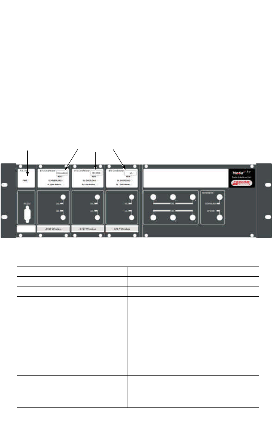
2.1.2 Front and Rear Panel Descriptions
RIU Front Panel
The RIU front panel provides all the indicators and LEDs. The unit is supplied with
the front-panel connections that summarize the signals of all conditioners into a
single signal that is applied to all BUs.
Figure 2-1. RIU Front Panel
Table 2-1. RIU Front Panel Indicators
LED Description
P.S UNIT PWR ON – input signal is at the required level.
BTS CONDITIONER RUN Flashing -- CPU is running and software loaded
BTS CONDITIONER DL OVERLOAD Continuous Red – RF switch is disconnected to
protect the system. This may be due to one of
the following reasons:
• Unpredicted power rise for which the
attenuation response was insufficient to
compensate and reduce the power to the
required level.
• Software problem detected.
Flashing: When the BTSC DL output power is
more than 3dB of the calibrated value.
BTS CONDITIONER DL LOW Continuous Red – if the BTSC DL power is at
least 15dB lower than the calibrated BTSC max
power level. This condition also triggers an
event.
Power indicator BTS Conditioners
MobileAccess™ 1000/1200 Module Description
MobileAccess 1000/1200 User’s and Installation Guide 3
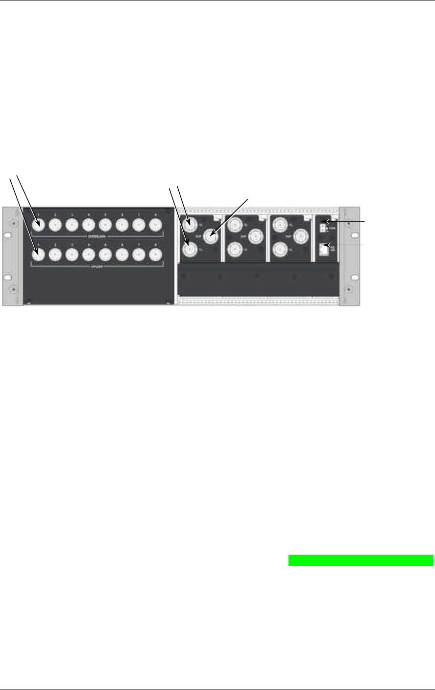
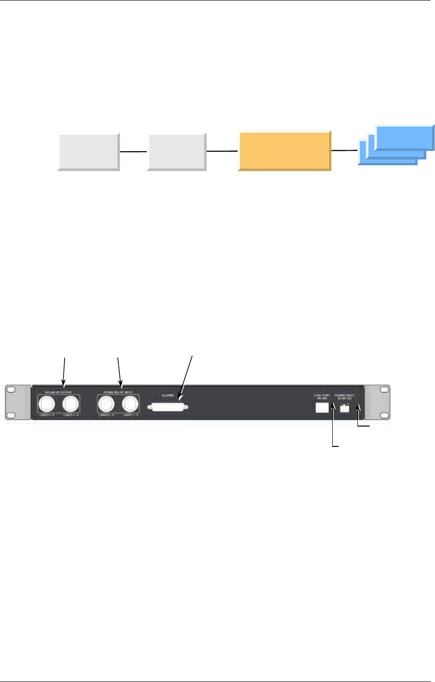
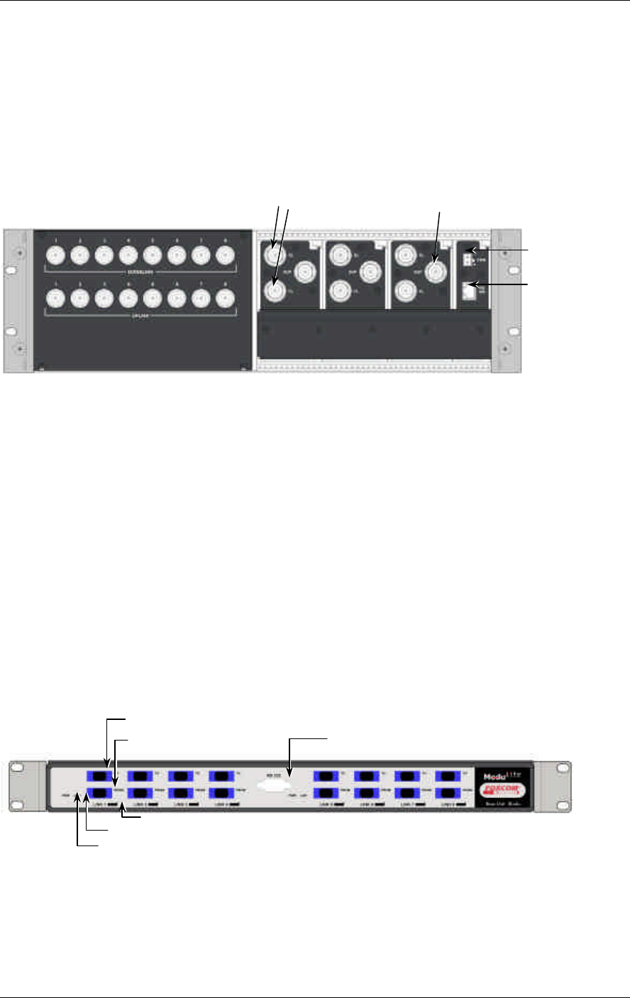
RIU Rear Panel
The rear-panel provides all the connections on the BTS side and on the BU side as
well as connections to the MobileAccess 410/430 controller and the power
connection. Two types of BTS side connections are available for each BTS
conditioner: non-duplexed and duplexed.
Figure 2-2. RIU Rear Panel showing the RF Connection
2.2 Base Unit
2.2.1 General
The Base Unit converts the downlink signal from the BTS or repeater from RF to
Fiber Optic and transmits it to the Remote Hub Units via a composite or F/O cable.
On the uplink, the BU converts the signal from Fiber Optic to RF.
Depending on the Base Unit model, each Base Unit drives up to four or eight
remotes via duplex F/O connection, where each remote can be as far as 2
kilometers (1¼ miles) from the BU. Eight port BU consist of two four port BU that
are integrated.
Each Base Hub Unit may be monitored and controlled via either a direct RS232
connection to a laptop on which the MobileAccess Configuration application (MCT)
has been installed, or via the MobileAccess 410/430 controller.
DC power input
MobileAccess 410/430
controller connection
Non-
duplexed connections
to a BTS or repeater Duplexed connections
to a BTS or repeater
Pairs of MobileAccess
1000 BU connections (pair
per BU)
Module Description MobileAccess™ 1000/1200
4 MobileAccess 1000/1200 User’s and Installation Guide
During power-up, the Base Unit identifies the active connected RHUs that are
connected to that Base Unit and each of the corresponding link LEDs is lit according.
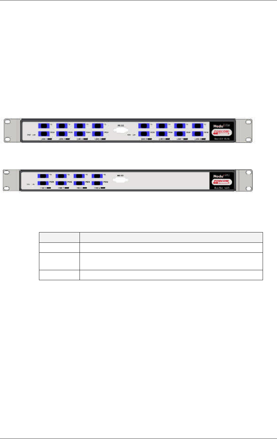
2.2.2 Base Unit Front and Rear Panels
The front panel contains all the optical connections while the rear panel contains all
the RF connections.
Front Panel
The following figures shows the front panel of an eight port BU and a four port Bu.
Figure 2-3. Eight Port MobileAccess 1000 Base Unit Front Panel
Figure 2-4. Eight Port MobileAccess 1000 Base Unit Front Panel
Table 2-2. MobileAccess 1000 Front Panel Indicators
LED Description
PWR Internal voltages OK. Two LEDs – one for each four-port module.
LSR Laser signal transmission is OK. Two LEDs – one for each four-port
module.
Link Detected optical signal received on that link.
MobileAccess™ 1000/1200 Module Description
MobileAccess 1000/1200 User’s and Installation Guide 5
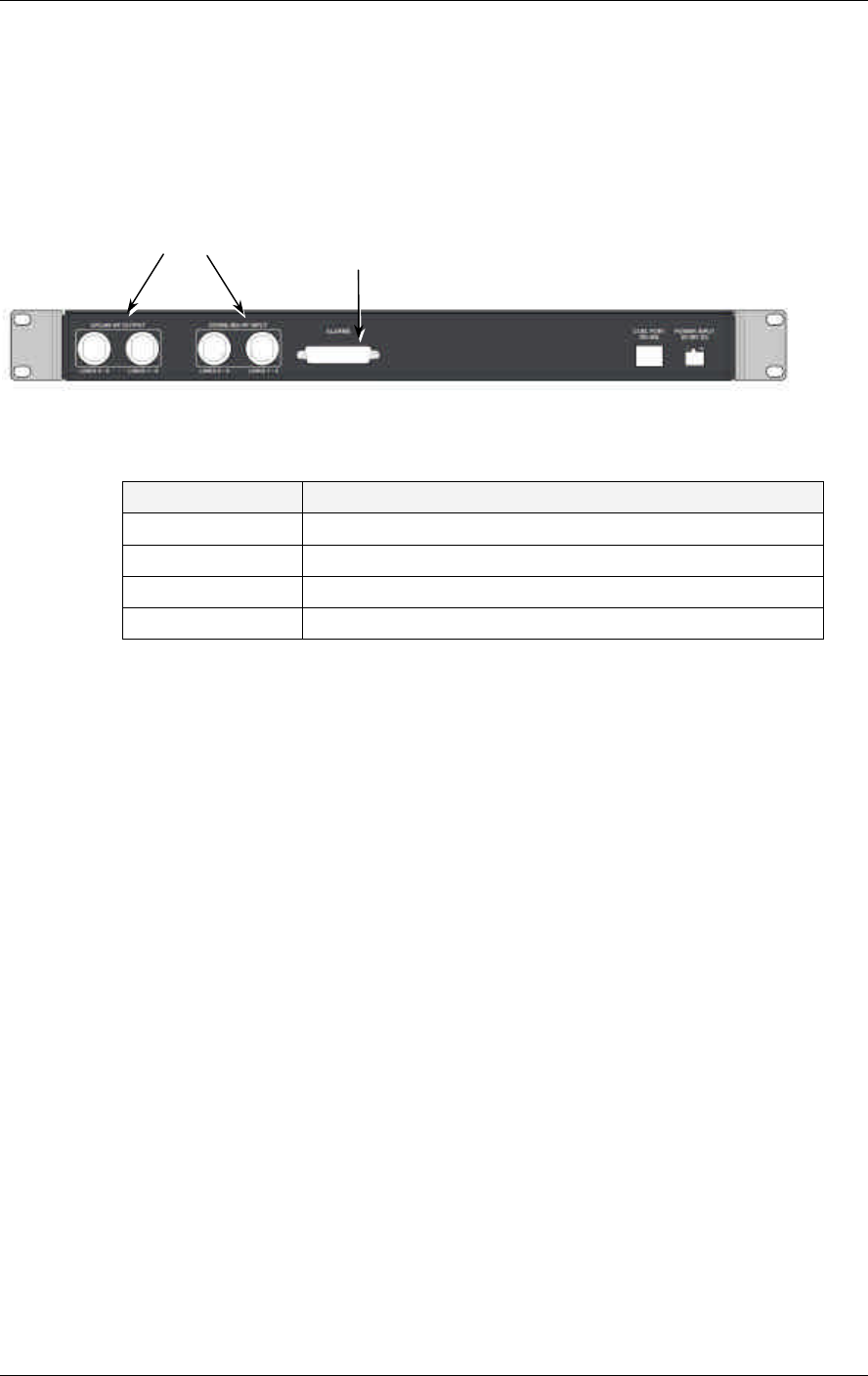
Rear Panel
The Base Unit rear panel on which the BTS side (RF) connections are located is
displayed by the following figure.
Figure 2-5. Base Hub Unit Rear Panel (RF Connections)
Table 2-3. MobileAccess 1000 Front Panel Indicators
Connector Description
Uplink output Uplink connectors to be connected on BTS side.
Downlink input Downlink connectors to be connected on the BTS side.
Com Port RS485 Connection to MobileAccess 410/430 controller.
PWR Power connection
Pair of uplink and downlink connections
for interface to BTS side (all four
connectors must be connected)
Alarms connector
Module Description MobileAccess™ 1000/1200
6 MobileAccess 1000/1200 User’s and Installation Guide
2.2.3 Remote Hub Unit (RHU)
On the downlink, the RHU converts the optical energy received from the BU back to
RF energy which is then delivered to the connected indoor antennas. On the uplink,
the RHU converts the RF energy from the antennas to optical energy which is then
delivered to the Base Units.
In order to make your system as flexible as possible and maximize the resources,
MobileAccess product line includes three models of RHUs:
• MobileAccess 1000 RHU
• MobileAccess 1200 RHU standalone
• MobileAccess 1200 RHU add-on
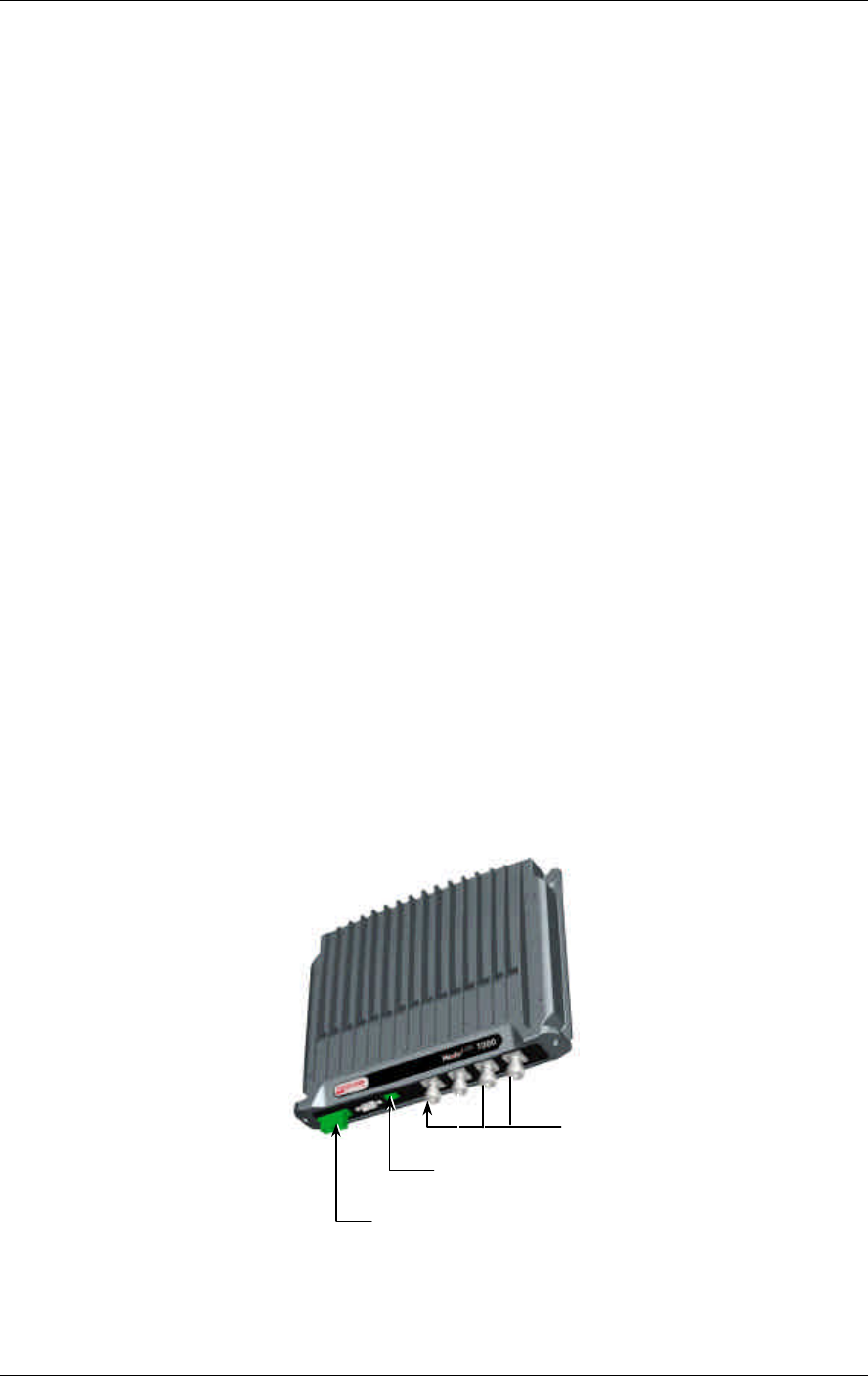
2.2.3.1 MobileAccess 1000
Each MobileAccess 1000 RHU unit can support two different frequency bands
depending on the RHU 1000 model. Output composite power per antenna port is in
the range of 14 to 20 dBm (depending on the served protocol).
MobileAccess 1000 can be purchase in one of the following models:
• Two-band RHU
• Two-band plus support for a third band (implemented using MobileAccess
1200 add-on unit)
Note: A third band may be added using the RHU 1200 add-on unit or RHU 1200 standalone unit (see
section xx for more details).
Cellular external
antennas
connections
Optical input/output
connectors to/from Base Units
DC power connector
MobileAccess™ 1000/1200 Module Description
MobileAccess 1000/1200 User’s and Installation Guide 7
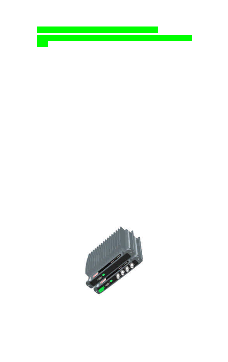
2.2.3.2 MobileAccess 1200
RHU 1200 is supplied in two configurations:
• MobileAccess 1200 add-on. This unit is installed on the MobileAccess™
1000 unit (supporting this option) . RHU 1200 add-on unit enables expanding
the RHU 1000 unit capabilities by an additional service. The supported band
varies depending on the model of the RHU 1200 add-on unit. RHU 1200 is
simply connected to the existing RHU 1000 unit.
• MobileAccess 1200 standalone unit. RHU 1200 standalone is a single-
band high power RHU. It consists of two sub-modules: an optical module that
provides the optics to RF conversion and the RF module that provides
amplification and power to the antennas.
Table 2-4: MobileAccess™ 1200 RHU Models
MobileAccess 1200
Catalog No. (RHU) Band (MHz)
1200 - UMTS - SA - R1U UMTS
1200 - UMTS - AO UMTS
1200 - PCS1900 - SA - R1U 1900
1200 - PCS1900 - AO 1900
1200 - DCS1800 - SA - R1U 1800
1200 - DCS1800 - AO 1800
1200 - CELL800 - SA - R1U 800
1200 - CELL800 - AO 800
Note: Detailed specifications for all models appear in the MobileAccessTM data sheet (421300220).
Figure 2-6. 1200 add-on unit Figure 2-7. 1200 standalone unit (TD)

Module Description MobileAccess™ 1000/1200
8 MobileAccess 1000/1200 User’s and Installation Guide
2.2.4 MobileAccess 410/430 Controller
NOTE: This section provides general information on the MobileAccess 410/430 Controller. For
detailed information onf the controller, configuration and connections refer to xxxx.
The MobileAccess controller enable managing and controlling the MobileAccess
system elements. Each controller provides connection to up to four Legacy Base
Units, or a total of up to eight MobileAccess Base Units and Radio Interface Units in
any combination. The RHUs (and antennas) are monitored via the Base Units.
Where support of more than four Legacy Bus or more than eight MobileAccess BU
and RIU elements is required, additional MobileAccess controllers, defined as a
“slaves” controller, can be added.
Slave controllers can also be used in a campus configuration where up to eight
Slaves can be connected to a single Master. All the monitoring and control
operations can be performed from the Master’s location.
Two MobileAccess controller configurations are provided: MobileAccess 410 and
MobileAccess 430. The models differ in their remote access capabilities:
• MobileAccess 410 provides point-to-point connectivity implemented via either
direct RS232 connection or via connection to a DSPN phone line
• MobileAccess 430 provides client/server management capability over TCP/IP
network with enhanced monitoring and control capabilities (in addition to the
connectivity options provided by MobileAccess 410).
NOTE: The MobileAccess 430 front panel is differentiated from the MobileAccess 410 front
panel by the SNMP Agent Card that provides TCP/IP management capabilities.
The controller front panel provides:
• LED indicators and an LCD display
• Local PC connections for monitoring
• For MobileAccess 430 only – TCP/IP connection and corresponding status
indicators
The controller rear panel provides connections to:
• Base Units – up to four Litenna and up to 8 MobileAccess
• Up to eight slave controllers
• Alarm outputs and inputs
• Modem connections for management connections
• Power
Note: The rear panels for the MobileAccess 410 and MobileAccess 430 are the same.
MobileAccess™ 1000/1200 Module Description
MobileAccess 1000/1200 User’s and Installation Guide 9
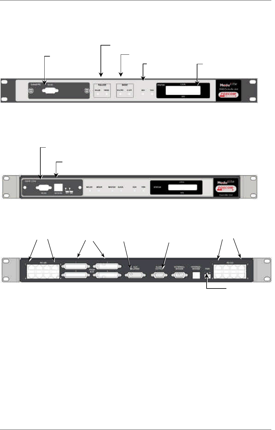
Figure 2-8. MobileAccess 410 Front Panel
Figure 2-9. MobileAccess 430 Front Panel
Figure 2-10. MobileAccess 410/430 Rear Panel
Local RS232
connection (for
IP address
setup)
LCD alarm display
corresponding to Major
and Minor LEDs
Major, Minor
LED
DC Input
Master/Slave configuration
Run and
Power LEDs
Local RS232 connection to
Laptop (RF2Litenna for Remote
controller)
TCP/IP connection
4 Litenna BU
connections
8 MobileAccess
BU connections
For Master -- 8 Slave
Controller connections
(via RF2Litenna uplink)
Input for general
purpose alarms
A
larm outputs
(BTS)

MobileAccess 1000/1200 User’s and Installation Guide 10
Chapter 3. Installation Procedure
This following installation procedure is based on the assumption that site survey and
installation planning (including power requirements) have been completed:
• Infrastructure preparation according to site analysis and planning: Fiber
Optic, coax cable and DC cable installation, Splice the fiber optic cable
according to the fiber optic infrastructure design plan.
• Individual floor installation: Install antennas and connect to coax, Install
Remote Hub Unit installation on each floor (mounting and connections).
• Communication room installation: RF interface (passive or RIU), Base Units
and MobileAccess 410/430 controller (mounting and connections).

MobileAccess™ 1000/1200 Installation Procedure
MobileAccess 1000/1200 User’s and Installation Guide 11
3.1 General
There are two types of installations: single-building and multi-building (campus)
configuration. This section describes the recommended Fiber Optics and system
location for both configurations. It is recommend to perform the following steps for
all MobileAccess installations (both single- and multi-building).
Single-building Installation
In this installation, all Base Units are placed in the same location (usually in the
communication room). The Base Units are connected to the BTS/RBS (or repeater)
via passive interface or via the RIU (Radio Interface Unit). RHUs are located in
various zones in the building according to the RF design. In a multiple story building,
a single RHU can typically cover a floor of up to 30,000 sq ft.
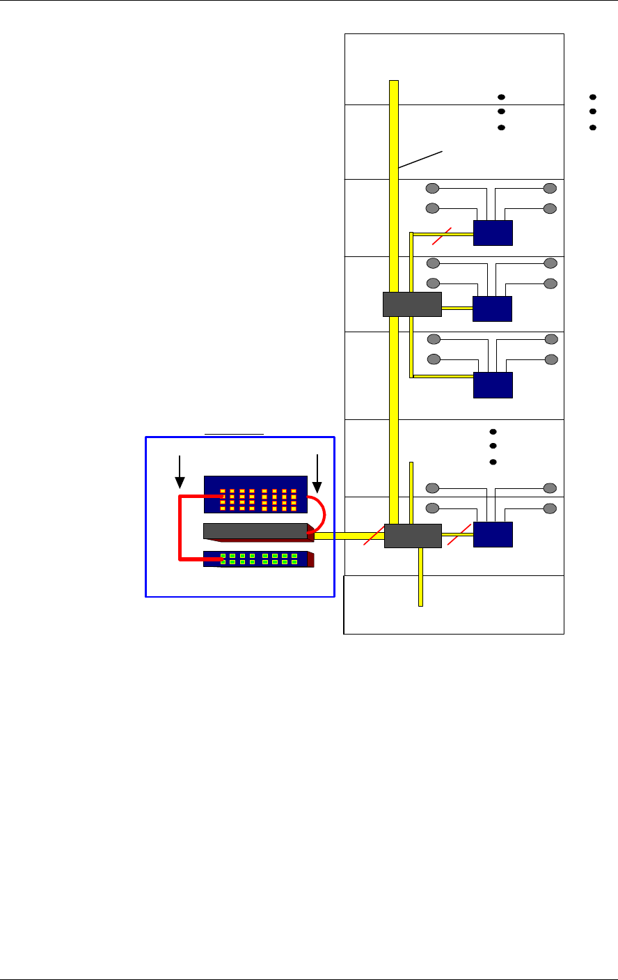
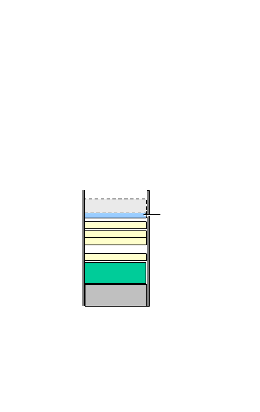
As illustrated in figure xx, the fiber optic cable runs from the communication room
(Base Units) through the building shaft. Usually every three floors, a fiber optic cable
is tapped to a splice box where it is distributed to the floor on which the splice box is
located, to the floor above and to the one below.
On each floor, the fiber is connected to the corresponding RHU where it is converted
to RF and distributed to the connected antenna(s) via coax cable.
Installation Procedure MobileAccess™ 1000/1200
12 MobileAccess 1000/1200 User’s and Installation Guide
Floor 9
Floor 2
MRC
2-8 Fibers
Fiber Optic
Cable
Floor 7
2-8 Fibers
Patch panel
Splice tray
MBU
PigTail
Jumpers
Splice
box
MRC
MRC
MRC
19" Rack
Splice
box
Floor n
Floor 8
MobileAccess™ 1000/1200 Installation Procedure
MobileAccess 1000/1200 User’s and Installation Guide 13
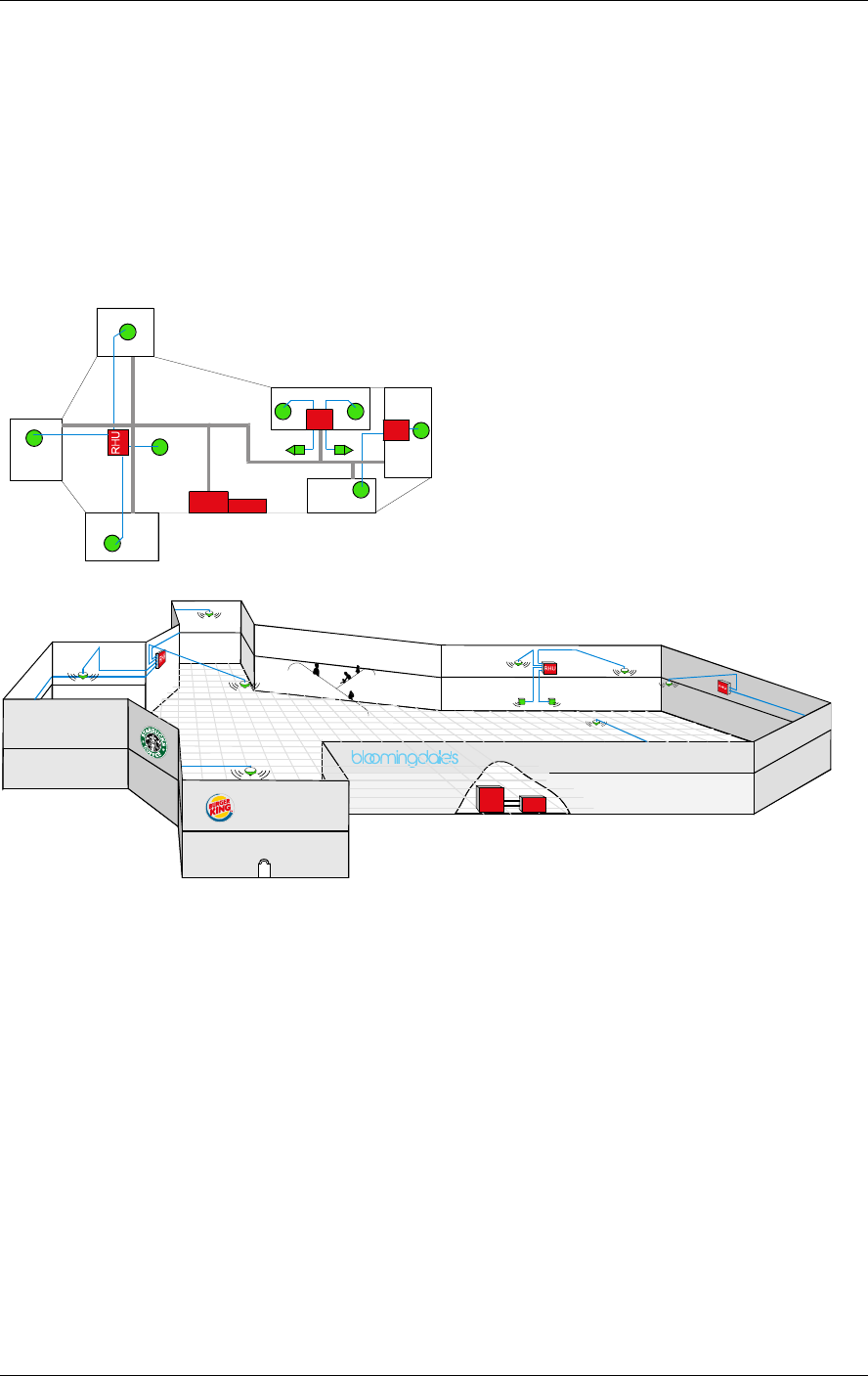
Example 2: Horizontal Structure
In a horizontal layout installation, a separate fiber optic cable is connected to every
site location, where a site may include more than one RHU. The connection may be
to a splice box or directly to the RHU (depending on the site confiugraiton).
A
C
G
H
E
CELL
SITEBASE
UNIT
F
I
D
B
RHU RHU
CELL
SITEBU
A
B
CD
E
F
GI
H
Figure 3-1: Horizontal Layout Installation

Installation Procedure MobileAccess™ 1000/1200
14 MobileAccess 1000/1200 User’s and Installation Guide
3.2 About Infrastructure Installation
Note: When working with fiber optics, it is crucial to maintain a clean working environment. However,
if the working environment has been tainted or if the optics connectors has not been covered, refer to
appendix x for information on cleaning the fiber optic cable.
ATTENTION: MobileAccess™ requires singlemode fibers with
SC/APC connectors. Be sure to use only these types of fibers.
Install all the insfratusture equipment according to the site plan. This procedure
includes:
• Installing the antennas. The antenna(s) are mounted to the ceiling, or are
embedded inside the ceiling tile, depending on the building construction.
• Routing the coax cables. These cables are routed between the antennas
and the location of the corresponding RHUs.
• Assembling coax connectors to either side of the coax cables.
• Routing Fiber optic cable backbone.
• Splicing the main routed fiber optic in the appropriate locations and installing
or placing the corresponding equipment (splice box, splice tray, patch panel,
etc.) in the appropriate locations.
Note: if these devices are installed in the 19” rack, be sure to place them as high as possible so
they will not interfere with the rest of the components that will be installed.
• Routing DC cables (see section xx for more info)

MobileAccess™ 1000/1200 Installation Procedure
MobileAccess 1000/1200 User’s and Installation Guide 15
3.3 Power Supply for the MobileAccess™
Note: Power to the MobileAccess™ modules may be supplied by any configuration of power supplies
that provide the necessary voltage and power.
It is recommended to calculate the required power according to the requirements of
the specific installation and then determine the configuration of the power supplies.
The required DC cables will then be determined by the selected PS configuration.
Following are the Power Supply configurations usually in use:
• Local configuration in which each PS unit is located adjacent to the BU or
RHU units (PS provide AC to DC conversion)
• Single source configuration in which all BU and RHUs are supplied from a
single location (i.e. high-rise)
• Mixed configuration in which a number of BU and RHUs are supplied from
each power supply (i.e. campus application where each building has a single
source)
The power required by each MobileAccess™ type unit is listed in the following table:
Table 3-1. MobileAccess™ Power Requirements
Unit Type Voltage Input Power Consumption
RIU 20 to 48VDC 10W
Base Unit 20 to 48VDC 10W
Remote Hub Unit
1000 20 to 48VDC 25W
Remote Hub Unit
1200 20 to 48VDC 30W
Various types of power supplies meeting these requirements may be purchased
from MobileAccess. The power supplies can be installed in a rack or mounted on a
wall, depending on your configuration. Four power supply options are available.
• Option One. In this option, the BU is connected to the power supply via
electrical cables. In order to power the RHU from the power supply, two
copper electrical wires running through the building (separately from the fiber
optic cables) supply power to each RHU in parallel. For this configuration,
electrical power calculations are needed. The option is shown in Figure 3-2.
• Option Two. In this option, the power supply is located near the BU. The
power supply will drive the BU and RHU’s. To provide power, the BU is
connected to the power supply via electrical cables. To supply power to the
RHU, a composite cable is used (composite cable contains two fiber cables
and copper electrical wires in the same jacket). For this configuration,
electrical power calculations need to be made.
• Option Three. In this option the power supply type is a standalone
configuration. Power for both the BU and RHU’s will be supplied separately.
In this configuration each unit will be co-located with a power supply. This will
not require long electrical cable runs.
Installation Procedure MobileAccess™ 1000/1200
16 MobileAccess 1000/1200 User’s and Installation Guide
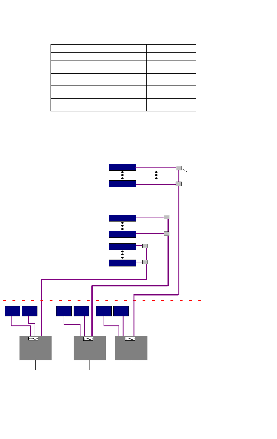
Table 3-2: Power Supply Options
Materials Model
Local power supply LPS-24-1A
Remote power supply (no
redundancy)
RPS-200-N-48
Remote power supply (fully
redundant) RPS-150-R-48
Remote power supply (fully
redundant) RPS-500-R-48
Remote power supply (fully
redundant) RPS-1000-R-48
The example in Figure 3-2 depicts a MobileAccess™ GSM Dual Band installation
with 500W/ 48VDC AC/DC converters providing a total of 0.5A power.
Between the AC/DC converters and the units, a circuit breaker (maximum 10A) must
be installed, either in the AC/DC converter or nearby.
AC/DC
2AC/DC
3
RHU 48
AC/DC
1
BU 4
48VDC 48VDC 48VDC
BASE
STATION
2.5mm
2
110/220
VAC 110/220
VAC 110/220
VAC
RHU 33
RHU 32
RHU 17
RHU 16
RHU 1
16mm2
2.5mm
2
2.5mm
2
16mm2
2.5mm
2
16mm
2
Clamping
Connector
BU 1 BU 2 BU 3 BU 6
BU 5
2.5mm
Fuse
10A Fuse
10A
Fuse
10A
2.5mm
2
2.5mm
2
Figure 3-2: EXAMPLE: DC Power Supply in High Rise Installation
MobileAccess™ 1000/1200 Installation Procedure
MobileAccess 1000/1200 User’s and Installation Guide 17
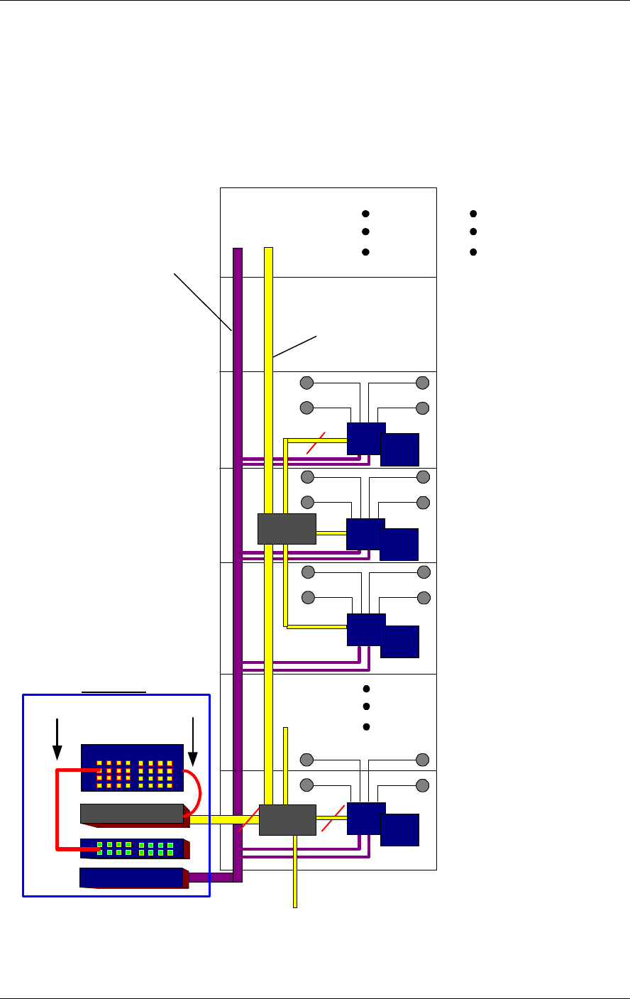
3.4 Rack Installation
It is recommended to install the following MobileAccess system modules in a 19”
rack (usually in the communication room):
• RIU 3U
• BU 1U
• MobileAccess 410/430 controller 1U
• Fiber Optic patch panel and splice tray– (previously installed – see section xx)
• Power supply/supplies (MobileAccess – 3U for each unit, other manufacuters
may vary in size)
Verify that the rack height can support all the units to be installed, where you may
also want to consider future expansions.
The following image describes shows the recommended locations of the
MobileAccess elements in the rack in order to facilitate and simplify the cabling
connections.
Note that the MobileAccess 410/430 controller is at eye level to provide an easy view
of the LED indicators and LCD display and easy access to the local and remote
monitoring connections.
MobileAccess Controller
(1U)
MobileAccess Base Unit 1
(1U)
MobileAccess RIU (3U)
MobileAccess
Power Supply (3U)
Fiber Optic Patch Panel
and Tray (variable)
MobileAccess Base Unit 2
(1U)
MobileAccess Base Unit 3
(1U)
At eye level
MobileAccess Base Unit 6
(1U)
Installation Procedure MobileAccess™ 1000/1200
18 MobileAccess 1000/1200 User’s and Installation Guide
3.5 Connecting Each of the MobileAccess
Elements
3.5.1 Base Unit Connections
The Base Unit converts the RF signal from the BTS side to optic signals to be
transmitted via optic fiber to the RHUs. Therefore, there are two types of
connections to each base unit:
• Base Unit to BTS side RF connections
• Base unit to RHU side optic connections
The BU may be connected in the following three configurations:
A) MobileAccess 1000 full configuration:
This is a typical MobileAccess 1000 configuration.
BTS
(operator) Passive
Interface ModuLite 1000 BU RHU
RHU
RHU
B) MobileAccess / Litenna configuration for backwards compatibility:
In this configuration the BU replaces an old BU in the old MobileAccess / Litenna
products.
The BU is connected to the BTS through a passive interface without a BTSC, and
has to perform exactly like the old BU. The issue here is that the passive interface is
previously calibrated to input powers that the old BU needed. The new BU has to be
able to adapt itself to these input powers.
BTS
(operator) Legacy
Passive Interface
ModuLite 1000 BU
(acting as Legacy) RHU
RHU
Legacy
RHU
MobileAccess™ 1000/1200 Installation Procedure
MobileAccess 1000/1200 User’s and Installation Guide 19
C) MobileAccess 1000 partial configuration:
In this configuration the BU is driven by a passive interface instead of a BTSC.
Unlike the previous configuration, the passive interface is supplied at the same time
as the BU, so the passive interface is calibrated to supply the input power normally
expected by the BU (as if a BTSC was connected).
BTS
(operator) Passive
Interface ModuLite 1000 BU RHU
RHU
RHU
3.5.2 Base Unit to BTS Side Connections
Base Units may be connected to the BTS/RBS/BDA either via passive RF interface
or via the Radio Interface Unit.
The Base Unit rear panel on which the BTS side (RF) connections are located is
displayed by the following figure.
Figure 3-3. Base Hub Unit Rear Panel (RF Connections)
3.5.2.1 Connections via Passive RF Interface
BTS/RBS/BDA Duplexed Configuration
4. Verify that the BTS/RBS/BDA is connected to a standard duplexer via a 50Ω
(RG223) coax cable.
5. Connect the downlink port through attenuators to the input on the Base Unit rear
panel, according to the required input power.
6. When more than one Base Unit is used, splitters are required to connect to the
other Base Unit inputs.
Connection to
MobileAccess
410/430 controller
DC
input
Pair of uplink and downlink
connections for interface to BTS
side (all four connectors must be
connected
)
Alarms connector
Installation Procedure MobileAccess™ 1000/1200
20 MobileAccess 1000/1200 User’s and Installation Guide
7. On the uplink side, combine the ports and connect them to the duplexer uplink
port via a 50Ω (RF 223) coax cable.
Note: All other cables are male to male 50Ω.
BTS
B4U
Duplexer
Attenuator
Figure 3-4: Example: One port BTS/RBS connected to 1BFU
BTS
2way
B8U
Duplexer
Attenuator
2way
Figure 3-5:Example: One port BTS/RBS connected to 1 B8U .
BTS/RBS/BDA Simplex Configuratoin
1. The BTS/RBS downlink port should be connected via 50Ω (RG223) coax cable
to the Base Unit input via an attenuator.
2. The downlink coax cable coming from the BTS/RBS should be split
using splitters to all Base Unit input ports (split according to need).
3. The input power for the Base Unit should be calculated to meet the
product specifications.
4. For the uplink only the necessary ports will be combined and
connected to the BTS/RBS uplink port with suitable splitter.
Note: All cables are coax jumpers (male to male 50Ω).
MobileAccess™ 1000/1200 Installation Procedure
MobileAccess 1000/1200 User’s and Installation Guide 21
BTS
Attenuator
B4U
Figure 3-6: Example: Two port BTS/RBS connected to B4U.
BTS
2 way B8U
Attenuator
2 way
Figure 3-7: Example: Two port BTS/RBS connected to B8U with six optic links
3.5.2.2 Connections via Radio Interface Unit (RIU)
Each RIU can support up to four 8-port Base Units. The RIU can be expanded to
support additional BU via the front panel connectors. Figure 3-8 shows the RIU rear
panel connections.
Note: All connections are via RG223 coax cables with 1/2" N-type male connectors
RIU to BTS/RBA/BDU connections
Note: Be sure to connect each service from the BTS side to the corresponding BTS conditioner
module.
The RIU can be interfaced to up to three BTS/RBA/BDU connections. Two types of
BTS connections are supported:
• Simplex BTS connection via an external duplexer.
• Duplex BTS connection via an internal duplexer.
Installation Procedure MobileAccess™ 1000/1200
22 MobileAccess 1000/1200 User’s and Installation Guide
RIU to Base Unit connections
Connect each Base Unit to the corresponding pair of RF outputs on the RIU rear
panel.
Figure 3-8. RIU Rear Panel showing the RF Connection
3.5.3 Base Unit to RHU connections
1. It is assumed that the patch panel cabinet (SC/APC adaptors) for fiber optic
cable connections is installed in the rack near the Base Units.
2. Connect (3/125/900) pigtail with SC/APC connectors between splice
tray and patch panel cabinet.
3. Connect (3/125/3000) SC/APC jumpers between the corresponding
Base Unit and patch panel.
4. Connect the fiber optic cables from the Base Unit to the RHU’s
through the patch panel cabinet.
DC power input
MobileAccess 410/430
controller connection
Non-duplexed
connections to a BTS
Duplexed connections
to a BTS or repeater
Laser output connection to
RHU
Optical diode input from RHU
Base Unit Laser operational LED
indicator
RHU LED indicators (Link 1
to 8)
RS232 connection for
monitoring
Power indicator
MobileAccess™ 1000/1200 Installation Procedure
MobileAccess 1000/1200 User’s and Installation Guide 23
3.6 Remote Hub Units (RHUs) 1000
1. Install splice box near RHU (refer to optic planning).
2. Connect fiber optic cable to splice box and (3/125/3000) pigtails to
RHU
3. For the downlink, connect the fiber optic cable pigtails from splice box
coming from the Base Unit port to the corresponding Remote Hub
Unit port.
4. Connect the Remote Hub Unit to antennas according to the RF
engineers design. (up to 4 antennas per RHU).
5. For the uplink, connect the fiber optic cable pigtails from splice box
from the Remote Hub Unit to the uplink port that connects to the Base
Unit.
6. Connect the power supply to each RHU according to power design
planning.
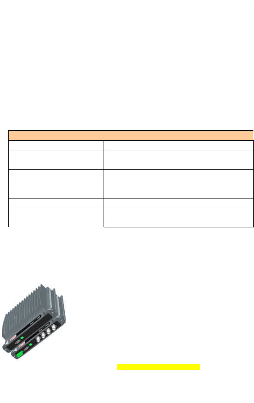
3.7 RHU 1200
3.7.1 Remote Hub Unit 1200 Add-on Unit
RHU 1200 does not require additional installation of either coax or fiber since the
optical to RF conversion and antenna connections are provided by the RHU 1000
unit.
The add-on RHU is connected to the corresponding RHU 1000 unit using SMA coax
jumpers at the rear of the units.
Figure 3-9. RHU 1000 with RHU 1200 add-on unit
Installation Procedure MobileAccess™ 1000/1200
24 MobileAccess 1000/1200 User’s and Installation Guide
To install the 1200 add-on unit
1. Remove all three SMA connectors.
2. Connect the Add–On unit with four screws to the installed RHU 1000.
3. Connect coax jumpers between units correspondently.
4. Connect power to the Add-On unit.
Add
on
Floor 9
Floor 2
RHU
2 Fibers
Fiber Optic
Cable
Floor 7
2 Fibers
Patch panel
Splice tray
B8U
PigTail
Jumpers
Splice
box
RHU
RHU
RHU
19" Rack
Power Supply
DC
Cable
Splice
box
Floor 32
Add
on
Add
on
Add
on
MobileAccess™ 1000/1200 Installation Procedure
MobileAccess 1000/1200 User’s and Installation Guide 25
3.7.2 Remote Hub Unit 1200 Standalone
RHU 1200 standalone unit provides high power support for a single band. The
supported band varies depending on the model of the RHU 1200 standalone unit.
The standalone RHU 1200 is connected to the communication center’s base unit by
two fiber optic strands
Figure 3-10. RHU 1000 with RHU 1200 add-on unit – wrong picture
To install the 1200 standalone
1. Connect BTS/RBS to Base Units via ½” coax cable RG223 or similar with 50Ω
impedance according the RF design.
2. In the remote end, install the RHU 1200 standalone in a shaft or wall
mount.
3. Connect two pigtail/jumpers fibers from the splice box to each unit.
One splice box can support several RHU’s according to the optical
design (normally three RHU’s).
4. Connect antennas to the Remote Hub Unit UMTS Ready via ½” or 3/8” or similar
coax cable with 50Ω impedance and N-type male to male.
5. Terminate all unused antenna ports (N-type for antennas) on the Remote Hub
Unit UMTS Ready with 50Ω load
B8U
RHU
GSM
900/1800
Optic In
Optic Out
3G port3
3G port2
3G port1
Optic In1
Optic Out1
Optic In8
Optic Out8
Figure 3-11:UMTS Ready -System Configuration
Installation Procedure MobileAccess™ 1000/1200
26 MobileAccess 1000/1200 User’s and Installation Guide
The following diagram depicts the upgraded remote site design:
B8U
RHU
GSM
900/1800
Optic In
Optic Out
3G port3
3G port2
3G port1
Optic In1
Optic Out1
Optic In8
Optic Out8
Add-onRHU
UMTS
3G port1
3G port2
3G port3
Figure 3-12: Example - MobileAccess™ UMTS Ready Full Installation
3.8 Controller Connections
The MobileAccess controller connections vary depending on the configuration of the
site and the required monitoring capabilities. The MobileAccess 410/430 controller
configuration is described in section xx .
3.9 Power Supply Connections
Connect the power supply to the units, according to power design planning.

MobileAccess 1000/1200 User’s and Installation Guide 27
Chapter 4. Adjustments Procedure
This procedure is used to adjust the system to provide optimal performance. The
system will be operational without this adjustment procedure; however, the system
performance will be better.
Adjustments can be made only after the system is fully installed. The adjustments
procedures differ depending on the system topology:
• With RIU
• Without RIU
• Main building adjustments
• Remote building adjustments
The adjustment procedure consists of three phases:
1. Performing auto-discovery and verifying that all system elements are detected.
2. Downlink adjustments
3. Uplink adjustments
4.1.1 Auto-detect
Before beginning the adjustment procedure, verify that all the system
elements are detected by doing the following:
1. If your Master controller is MobileAccess 430 (with a TCP/IP) slide-in board,
replace the TCP/IP slide-in board with an RS-232 board without TCP/IP.
2. Connect a laptop on which the MCT application is installed to the Master
controller RS232 front panel connector.
3. Launch the MCT application. The application will perform auto-discovery and a
Browser tree with all the system elements will be displayed.
4. Verify that all the installed system elements are displayed in the list. You may
now begin to perform the downlink adjustment procedure.

Adjustments Procedure MobileAccess™ 1000/1200
28 MobileAccess 1000/1200 User’s and Installation Guide
MobileAccess™ 1000/1200 Adjustments Procedure
MobileAccess 1000/1200 User’s and Installation Guide 29
4.1.2 Downlink Adjustments
The adjustment procedure is performed after the system installation is completed.
The procedure requires injecting a signal equivalent to that provided by the BTS.
This can be done by either using a signal generator or simply connecting the BTS.
If using a signal generator, set it up as follows:
• Frequency – mid-band frequency of the Operator’s range
• Amplitude – equal to the maximal expected composite RF transmitted by the
BTS
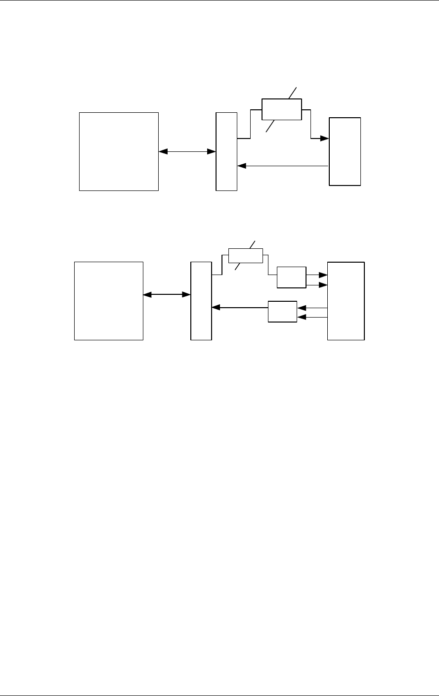
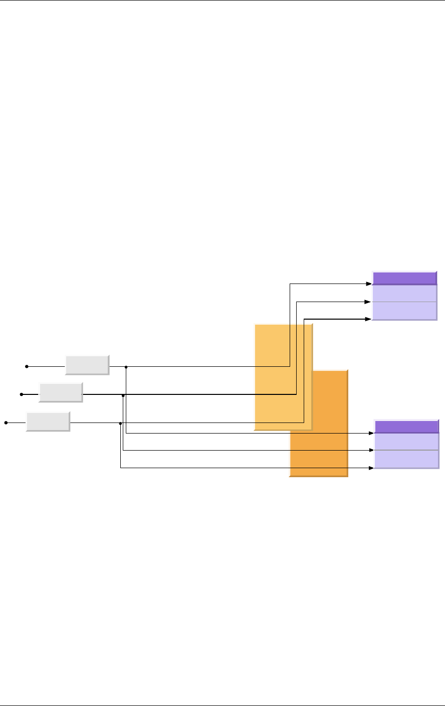
4.1.3 Main or Independent Building with RIU Adjustment
The DL path can be calibrated using either an injected signal that physically
represents the maximum input power expected from the BTS or using an estimation
of the same power level.
Maximum expected power
as given by the operator
BU 1
Adjust BTSC
output power
Adjust Laser Input Power to the
optimal level required for
conversion to F/O
Adjust according to
specific LOW band frequency
First band
-- adjust BTSC, each BU, and each RHU in the
relevant band.
Second band
- adjust BTSC, and each RHU in the relvant
band. No BU adjustment needed since each BTSC inputs
a third of the the power. Once the BU is adjusted, the
adjustemnt holds for any number of BTSCs (1, 2 or 3).
Do not adjust the BU while more than one BTSC is
transmitting.
Third band
-- adjust Add-on if relevant.
BTSC 3
(Add-on band)
RHU High band
RHU Low band
RHU 1200 Add-on
Adjust according to
specific HIGH band frequency
Adjust according to
ADD-ON frequency
BTSC 1
(Low band)
BTSC 2
(High band)
RHU High band
RHU Low band
RHU 1200 Add-on
BU 2
Adjust
Adjust
Adjust
Figure 4-1. Main or Independent Building with RIU
4.1.4 First Band Adjustment
4.1.4.1 First Band (any of the bands)
For the first band, adjustments are made end-to-end from the BTSC, through to each
of the connected BU and to each of the corresponding RHUs.
1. Connect either the signal generator or the BTS to either the duplex or non-duplex
connectors of one of the BTSC units (i.e. BTSC #1).
NOTE: The signal generator must be set to mid range frequency and maximum power, while BTS
must be set to test mode with all carriers on.

Adjustments Procedure MobileAccess™ 1000/1200
30 MobileAccess 1000/1200 User’s and Installation Guide
2. Verify that the MobileAccess RS232 slide-in panel is inserted in the
MobileAccess 410/430 controller and connect the laptop to on which the MCT
application is installed to the RS232 front panel connector.
3. Launch the MCT application, double-click on the first BTSC element (i.e. BTSC
1) in the Topology tree, and access the Adjustments pane.
4. Select the type of adjustment (Live or Emulated signal source) and click Adjust.
A message will appear indicating if the procedure was successful or failed.
If the procedure was successful the parameters will be stored.
5. If the procedure failed, the cause will be indicated. In addition, if the procedure
failed, the BTSC will retain the parameters of the last successful adjustment
procedure.
.
Second Band (any of the other bands)
1. Connect either the signal generator or the BTS to either the duplex or non-duplex
connectors of one of the BTSC units (i.e. BTSC #1).
NOTE: The signal generator must be set to mid range frequency and maximum power, while BTS
must be set to test mode with all carriers on.
2. Launch the MCT application, double-click on the next BTSC element (i.e. BTSC
2) in the Topology tree, and access the Adjustments pane.
3. Select the type of adjustment (Live or Emulated signal source) and click Adjust.
A message will appear indicating if the procedure was successful or failed.
If the procedure was successful, the parameters will be stored.
4. If the procedure failed, the cause will be indicated. In addition, if the procedure
failed, the BTSC will retain the parameters of the last successful adjustment
procedure.
.
The BTSC embedded SW will carry out the following scenario. Note: The DCA value is set in the factory to 31 (– max
attenuation).
The leds DL OVERLOAD and DL LOW SIGNAL will serve as indications during the
adjustment as described in the block diagram. Upon success the sw will calculate
Pin (see the method in DL ‘dry’ adjustment section) and store it.
4.1.4.2 First band downlink adjustment

MobileAccess 1000/1200 User’s and Installation Guide 31
Appendix A. Frequently Asked
Questions
1. What are the BU and the RHU, and for what are they used for?
The MobileAccess™ system consists of two modules: Base Unit and Remote Hub Unit. The Base Unit interfaces
between the microcell or base station and the Remote Hub Unit (RHU). The interface is via either a composite cable
or fiber optic cable. In this description, on the downlink path, the Base Unit converts incoming RF signals to optical
signals, transmitting these signals over fiber optic cable to the RHU. The RHU converts the optical signal back to RF.
The RHU drives the four connected antennas. On the uplink path, the RHU combines and converts incoming RF
signals from the four antennas into optical signals, transmitting these signals back to the Base Unit. The Base Unit
converts the signals back into RF signals.
2. How does the BU connect to the RHU, and which fibers and connectors are required?
The BU connects to the RHU via fiber optic cable. The system uses 2 fibers for each RHU connection, one fiber for
the uplink and one fiber for the downlink. The MobileAccess™ system requires singlemode fibers and SC/APC
connectors.
3. How many RHU’s and antennas are required for each floor in a building?
Determine the number of RHU’s and antennas per floor depends on the building size and configuration. Each RHU
can support up to four antennas. It is possible to connect several BUs together in one installation, increasing the
amount of available RHU’s. With one BU able to support up to eight RHU’s, this translates to up to 32 antennas.
4. Is the RHU and BU power supply AC or DC? and what is the voltage level?
The power needs of the BU and RHU are supplied by DC power. The voltage level is 18V-48V. MobileAccess offers a
power supply for the BU as well as the RHU. The power supply options are a Remote-located power supply, or a
Local power supply.
The Remote-located power supply is located near the BU. This power supply drives the BU
and the RHU’s. To provide power, the BU is connected to the power supply via electrical
cables. For power to the RHU, a composite cable can be used. [A composite cable contains
two fiber cables and two copper electrical wires in the same jacket]
The Local power supply provides power to the BU and to the RHU separately. A Local power supply is co-located with
each BU and RHU, not requiring long electrical cable runs.
5. Can the RHU be used in outdoor applications?
Currently, the RHU can be used only for indoor applications. The RHU can be upgraded for outdoor applications.
6. What type of antennas can be used?
All antennas types (appropriate to the cellular standard used) can be used for the MobileAccess™ system, including
leaky coax.
7. Does the RHU require a dedicated power supply or can it be powered by remote?
The RHU can be supplied with a local power supply, or by a remote powering DC cable over fiber optic cables
(composite cable).
8. Can the MobileAccess™ Base Unit be connected to the BTS/Microcell/BDA/off-air repeater?
The MobileAccess™ BU can be connected to the following: BTS, Microcell, Off-air Repeater (with virtually no
modifications).
9. Does the MobileAccess™ require any special tuning or adjustments during the installation?
The MobileAccess™ doesn’t required any special tuning or adjustments during the installation.
10. Does the MobileAccess™ support multi services, like GSM Dual band?
The MobileAccess™ system is upgradable to support multi services over the same fiber cable, like GSM Dual-Band
(900/1800). The system will also be available as a field modular system for UMTS (3G).
11. What are advantages of the MobileAccess™ compared to a coax solution?
The MobileAccess™ advantages over coax are: Low cost per antenna, easy to install and maintain, flexible
placement, easy to configuration, and future proof.

Adjustments Procedure MobileAccess™ 1000/1200
32 MobileAccess 1000/1200 User’s and Installation Guide
12. What is the RF input power required at the Base Unit?
The required composite RF input power at the Base Unit is between 0dBm to 7dBm, depending on the operating
standard.
13. What alarms are in the system, and how can they be transmitted to a central monitoring system?
The MobileAccess™ system can support 3 alarm options: Dry Contact alarms
(Normally Closed), Dry Contact alarms (Normally Open) and open collector alarms.
The alarms can be applied to every link or as a major alarm.

MobileAccess 1000/1200 User’s and Installation Guide 33
Appendix B. : Link Measurements
Form
To smoothly carry out link measurements, refer to table Table 4-2: Fiber optic Cable
Test Results. This table aids system evaluation and provides necessary feedback to
MobileAccess.
The following issues should be taken into account:
• Measure the optical power for every link with an optical meter and light
source, according to the number of links or RHU’s.
• Measure the typical signal strength (RSSI) for every installed antenna.
• Check coax cable connection between RHU and every installed antenna.
Table 4-1: Link Measurement Table
System
Link
Power Meter
(mW) RSSI (dBm)
Coax Cable (OK/Fail)
Ant1 Ant2 Ant3 Ant4 Ant1 Ant2 Ant3 Ant4
RHU1
RHU2
RHU3
RHU4
•
•
•
•
•
•
MobileAccess 1000/1200 User’s and Installation Guide 34
Appendix C. Fiber Optic Cable
Instructions
Fiber Optic Cable
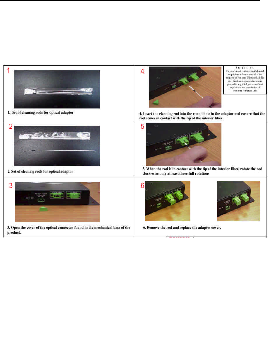
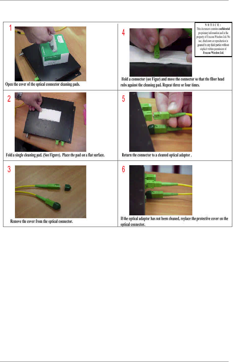
Before connecting the cable, clean the inside adaptor of the MobileAccess™
according to the following instructions:
MobileAccess™ 1000/1200 Adjustments Procedure
MobileAccess 1000/1200 User’s and Installation Guide 35

MobileAccess 1000/1200 User’s and Installation Guide 36
NOTE: In order to explain the testing procedures, the terms related to these tests need to be explained.

MobileAccess™ 1000/1200 Adjustments Procedure
MobileAccess 1000/1200 User’s and Installation Guide 37
Appendix D. Fiber Optic Cable –
Terms
Fiber optic cable is produced in a variety of formats with different characteristics. The
following terms define the various aspects of fiber optic cable:
• Fiber optic cable
• Jacket
• Buffer
• Fiber
• Optical fiber
• Core
• Clad
• Singlemode
• Multimode
• Fiber optic connection
• Splice
• Fusion
• Mechanical
• Connector
• Bending Loss -- Minimum bending radius
• Coupler
Optical Fiber
Fiber optic cable is described by the amount of fibers contained within. The cable
described by the following terms:
• Glass. Glass is the middle fiber in the cable. The data sent over the cable
travels through the glass.
• Buffer. The buffer is the plastic coating that covers the fiber optic cable. The
buffer protects the glass from moisture and other damage.
Adjustments Procedure MobileAccess™ 1000/1200
38 MobileAccess 1000/1200 User’s and Installation Guide
• Jacket. The jacket covers the buffer, providing greater protection to the
glass.
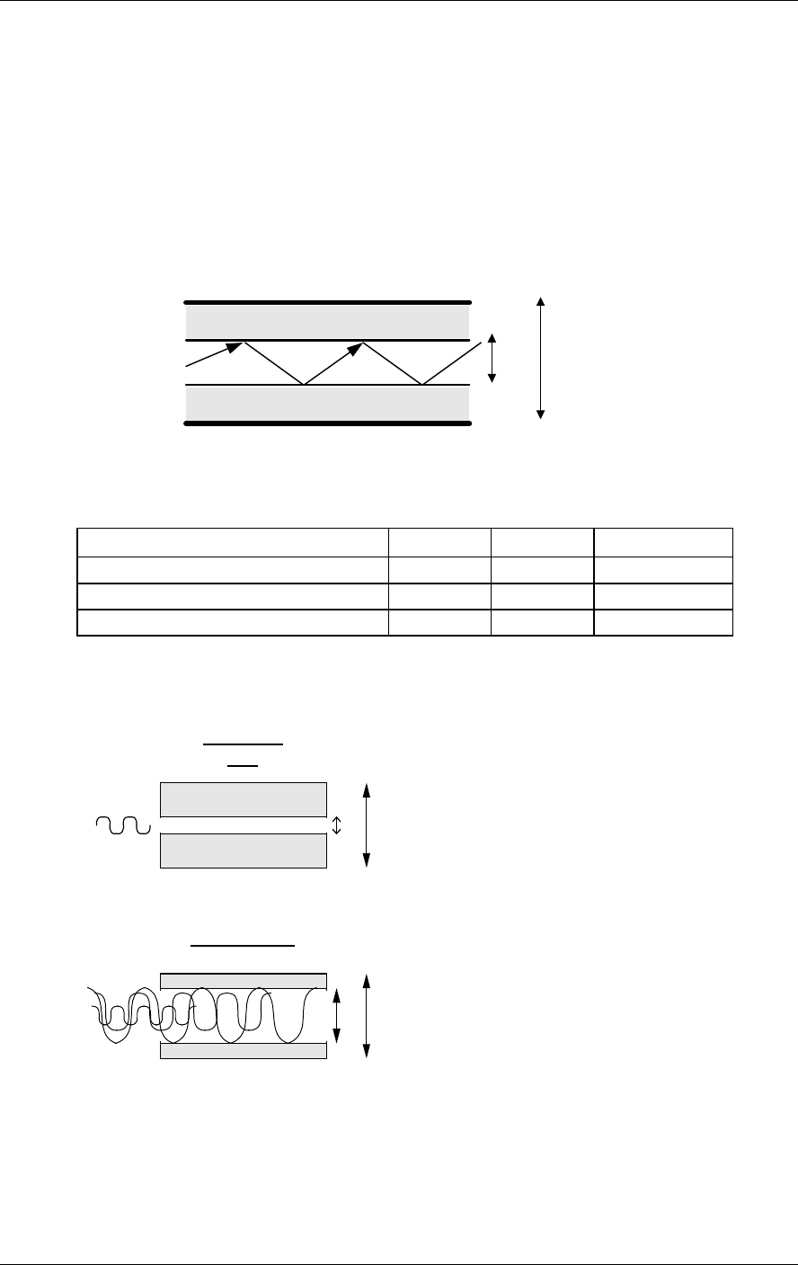
The fiber consists of Core and Clad. The central part of a fiber is known as the core,
and the material surrounding the core is known as the clad. The clad has a lower
index of refraction than the core, allowing light to be completely reflected off the
surface between the core and the clad. As a result, propagated light remains entirely
within the core. The cross-section of the cable is expressed as the core diameter
followed by the clad diameter. For example, a 9/125 fiber has a core diameter of 9µ
m and a clad diameter of 125µm.
core
clad {
{
{
clad
Figure 4-2: Fiber Optic Cable Structure
The cables are available in two different modes, each with different propagation properties:
Property Core Clad Attenuation
Singlemode 9 µm 125 µm .38 dB/Km
Multimode 50 µm 125 µm 1 dB/Km
Multimode 62.5 µm 125 µm
λ1
9 125
Singlemode
fiber
λ1
50 125
Multimode fiber
λ2λ3
@1310nm
(For illustration only)
Figure 4-3: Singlemode - Multimode Fibers
9
µ
m 125
µ
m

MobileAccess™ 1000/1200 Adjustments Procedure
MobileAccess 1000/1200 User’s and Installation Guide 39
Connecting Fiber Optic Cable
In order to carry out a fiber optic connection a Splice and a Connector are required.
• Splice. A splice consists of cutting the fiber optic cable across the cable’s
diameter and combining the opening with another fiber optic cable. A splice
can be carried out in the following methods:
• Fusion – following the splice, the cables are warmed and the two fiber optic
cables are melted together.
• Mechanical – following the splice, a hard connection is made between the
two fiber optic cables.
• Connector. In order to add or connect additional fiber optic cable, a
connector is used to make the connection. There are several types of
connectors:
• FC/PC
• SC/PC
• SC/APC (used by MobileAccess™)
Fiber Optic Cable Bending Loss
When the cable has bends or interior irregularities, then the optical signal becomes
weaker, known as Bending Loss. The sharper the bend – the greater the loss. Such
losses increase the cable’s attenuation.
Note: When installing fiber optic cable, the minimum bending radius needs to be noted in order to
prevent excessive bending of the cable, causing additional loss.
Coupler
Light from the cable can be split or combined, using a Coupler. Couplers split light
with minimal loss, from one to two fibers or combine light from two fibers into a single
fiber.

MobileAccess 1000/1200 User’s and Installation Guide 40
Appendix E. Optical Test Procedure
This section describes the methods applied to test fiber optic cable’s optical insertion
loss and return loss.
Fiber Optic Cable Test
Due to the extended distances that analog signal transmissions travel on cable, the
major challenge is to determine the status of the cable.
In order to determine that the cables are functioning, technical personnel need to
perform optical power tests.
The optical power tests covered in this document are:
• Optical insertion loss measurement test
• Optical return loss measurement test
MobileAccess System Characteristics
The MobileAccess™ system consists of the following characteristics:
• Singlemode fiber
• Wavelength 1310nm
• Fiber Optic Cable Measurement Tests
Cable can be measured through several procedures. This document describes the
following tests:
• Optical insertion loss measurement test
• Optical return loss measurement test
These tests are intended to be performed by technical personnel that deal with
MobileAccess systems. Other equipment can be used to perform these tests,
however the results have to be the same as will appear in the fiber optic cable test
results table (Table 4-2), at the end of this document.
The insertion loss measurement determines whether the optical signal power
traveling the cable length is strong enough to be received by the photo diode, in the
receiver.
Following the completion of the insertion loss test, the return loss test determines the
optical signal power that returns to the laser. The return power affects the laser,
changing the laser’s base current.
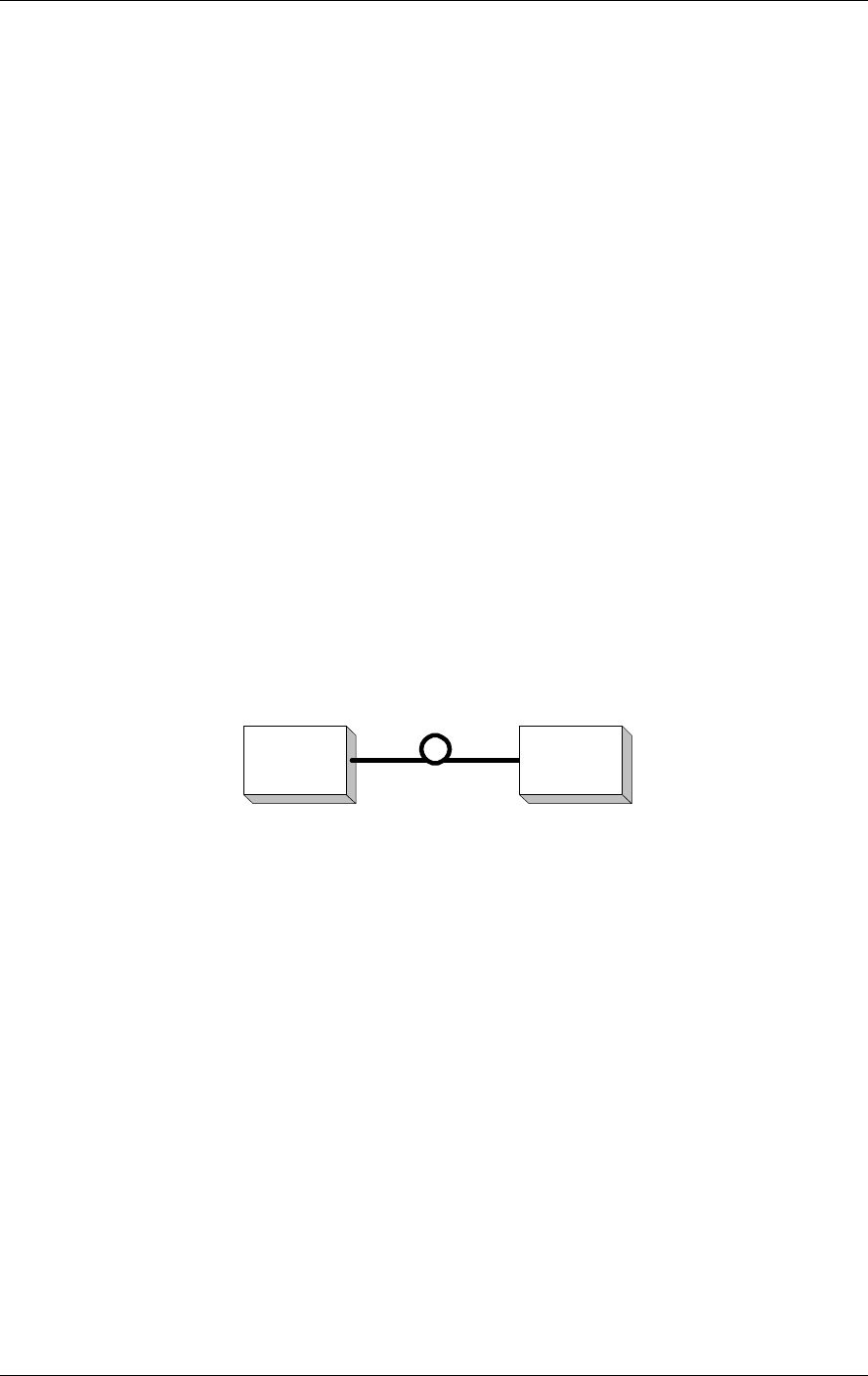
MobileAccess™ 1000/1200 Adjustments Procedure
MobileAccess 1000/1200 User’s and Installation Guide 41
Test Equipment
In order to perform these tests, the following equipment is necessary:
• Light source (for wavelength 1310nm , 0dbm)
• Optical power meter
• Optical coupler (hosed and connectorized)
• Fiber optic jumper
• Adapter parts for the cable connectors
For information about equipment suppliers, contact MobileAccess.
Optical Insertion Loss Measurement Test
The optical insertion loss measurement tests the attenuation of the cable. The
insertion loss’ value should be minimal and remain in scale to 0.4dB/Km.
The insertion loss measurement can be performed in two methods:
• Two point test
• Single point test
Method #1: Two Point Test
Connection description: Light source connected at one end of the cable and an
optical power meter at the other end.
Light
source
Optical
power
meter
Figure 4-4: Two Point Test
1. Connect light source directly to the optical power meter.
2. Measure light source signal power, verifying power of 0dBm.
3. Connect light source to cable end.
4. Connect optical power meter to cable at other end.
5. Measure light source signal power using the optical power meter.
6. Calculate the difference between two signals (dB):
(Insertion loss)dB = (Light source signal at one end)dBm – (Measured signal at other end)dBm
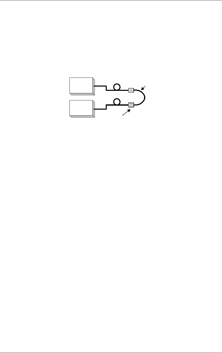
Adjustments Procedure MobileAccess™ 1000/1200
42 MobileAccess 1000/1200 User’s and Installation Guide
Method #2: Single Point Test
Connection description: This method assumes that there are two parallel fibers on the path to be
tested. Connect fiber jumper at end of the cable being tested to another parallel cable. Connect
the light source, optical power meter and optical jumper as shown in Figure 4-5. This
measurement can test two cables simultaneously.
Light
source
Optical
power
meter
Connector
Fiber optic jumper
Figure 4-5: Single Point Test
1. Use optic jumper to connect the two cables.
2. Connect light source directly to the optical power meter.
3. Measure the power of light source signal , verify power of 0dBm.
4. Connect a light source and optical power meter to one end of each cable.
5. Measure the power of the signal.
6. Calculate the difference between the two signals in dB
(Insertion loss)dB =(Light source signal)dBm– (Measure signal)dBm
Other Test Equipment
The optical insertion loss measurement test can be performed with more sophisticated
measurement equipment.
For information on other types of test equipment contact MobileAccess.
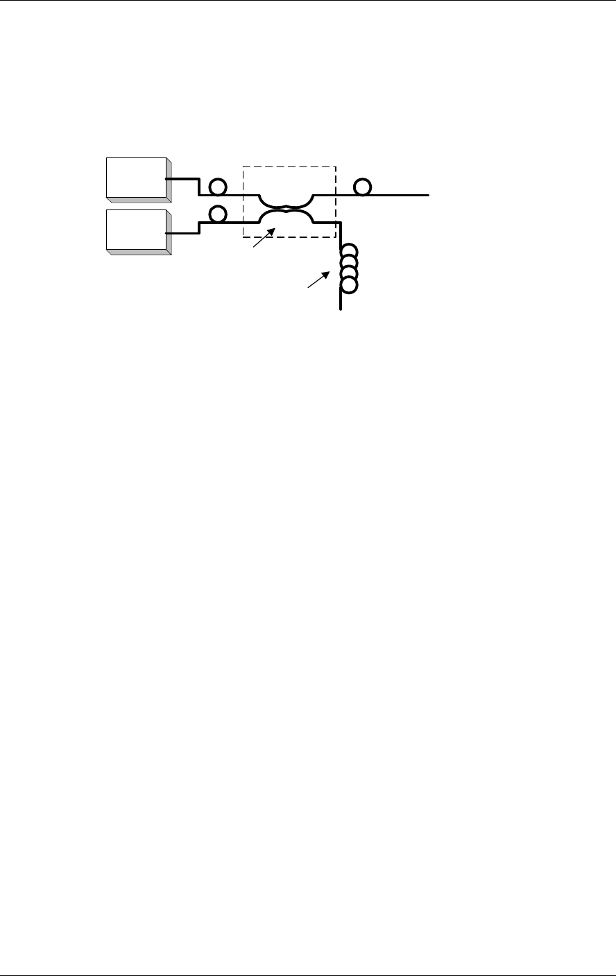
MobileAccess™ 1000/1200 Adjustments Procedure
MobileAccess 1000/1200 User’s and Installation Guide 43
Optical Return Loss Measurement Test
Connection description: Connect a light source and optical power to the inputs. If the
coupler has one output, connect the tested cable to this output. If the coupler has
two outputs make a pigtail at the second output.
Light
source
Optical
power
meter
IN OUT
(pigtail)
Cable Being Tested
2
13
4
"Optical Terminator"
Optical Coupler
Figure 4-6: Optical Return Loss Measurement
Measurement Procedure
Measuring Power Input To Cable Being Tested
• Verify that light source power is at 0dBm.
• Connect a light source to connector #1.
• Connect optical power meter to connector #3.
• Measure signal power (P3), power should be approximately –4dBm.
Measuring Coupler Power Loss
• Move power meter from connector #3 to connector #2.
• Move light source from connector #1 to connector #3.
• Measure power loss of coupler (Lc).
Measuring Return Power
To measure return power:
• Move light source from connector #3 to connector #1.
• Connect cable being tested to output connector #3.
• If coupler has two outputs, then make a pigtail at second output.
• If cable is longer than 100 meter, then cable needs to be isolated.
To isolate cable:
Find place near test point where winding the cable into a pigtail is possible.

Adjustments Procedure MobileAccess™ 1000/1200
44 MobileAccess 1000/1200 User’s and Installation Guide
Make pigtail.
If cable is shorter than 100 meter, then verify that cable is disconnected at end.
Measure the return light power (P2), connector #2.
Calculating Return Loss
Calculate the difference between the signals in dB.
(Return loss)dB = (P2)dBm – (P3)dBm + (Lc)dB
Results
The following table is to be filled in by technical personnel testing the fiber optic cables.
Table 4-2: Fiber optic Cable Test Results
Test Measurement Pass Range Pass/Fail
Optical insertion loss <0.5 dB/Km
Optical return loss < -50 dB
Summary
If the fiber fails in the optical insertion loss or optical return loss tests, then the
connector needs to be cleaned. Connector cleaning is carried out according to a
standard cleaning procedure. Following cleaning, the fiber needs to be tested again.
If the failure continues in the fiber following cleaning, then the technical personnel
need to refer to the fiber optic cable manufacturer’s troubleshooting guide.If the fiber
passes the optical insertion loss and optical return loss tests, then the tested fiber
optic cable is considered suitable for use with MobileAccess equipment