Corning Optical Communication MA1000WIMAX ENCOVER 1000 WIMAX DISTRIBUTED ANTENNA SYSTEM User Manual WiMAX Reference Guide 01 JULY 09
Corning Optical Communication Wireless ENCOVER 1000 WIMAX DISTRIBUTED ANTENNA SYSTEM WiMAX Reference Guide 01 JULY 09
Users Manual

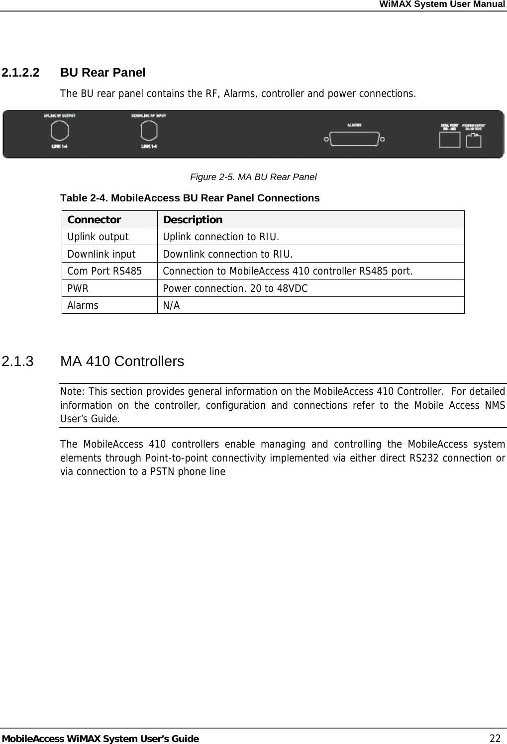
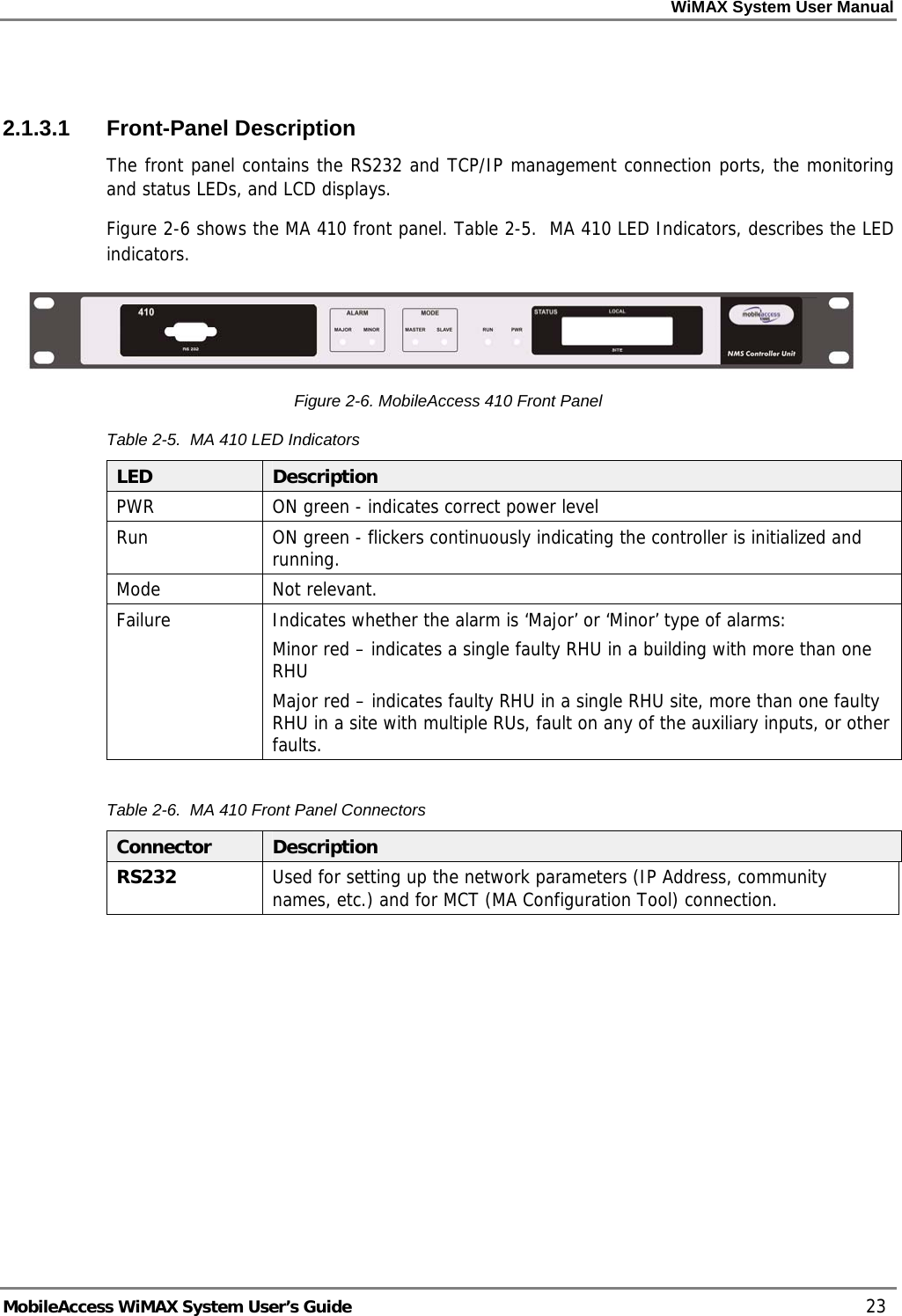
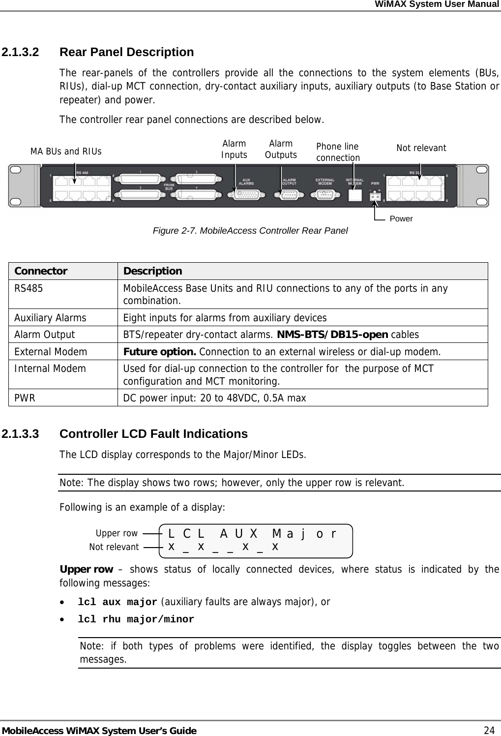
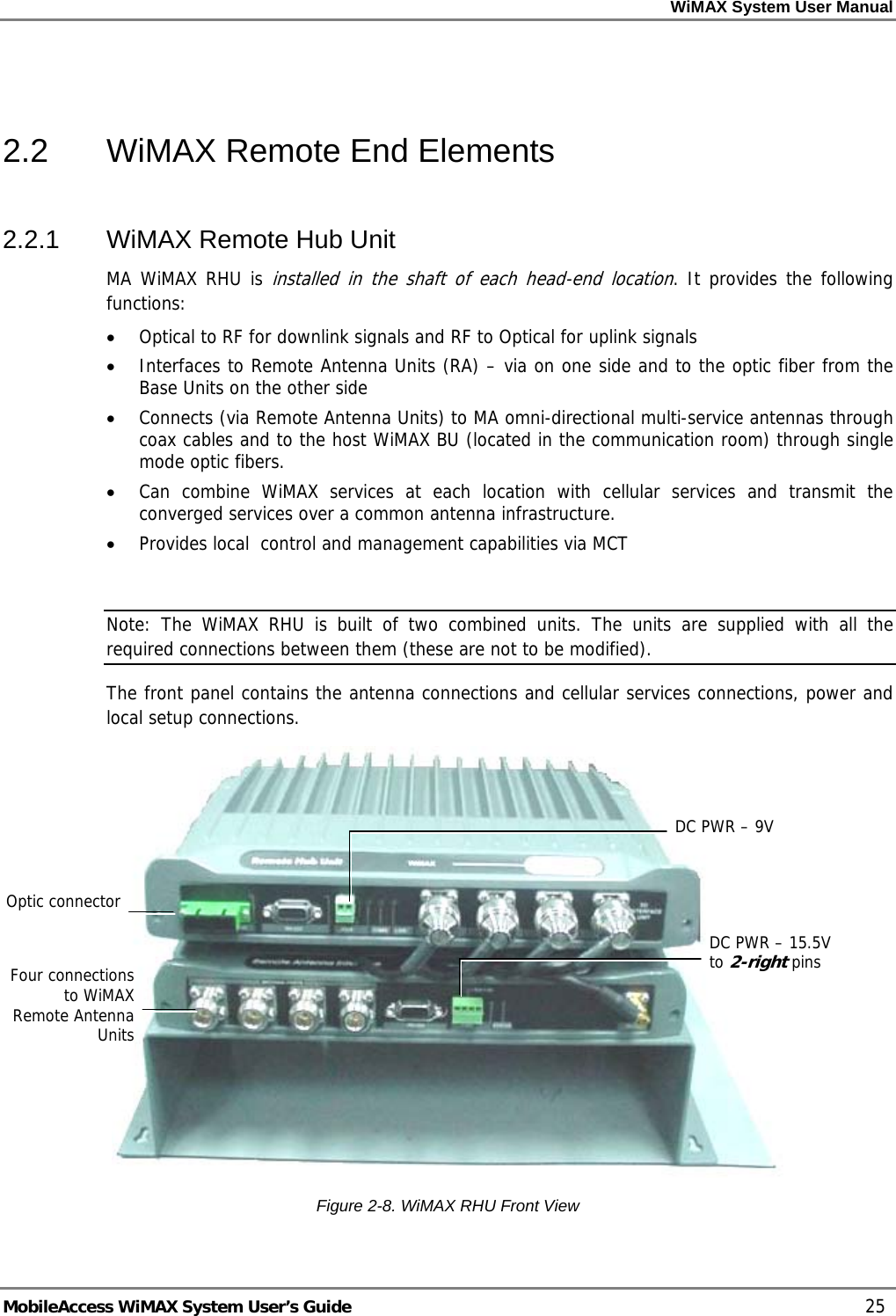
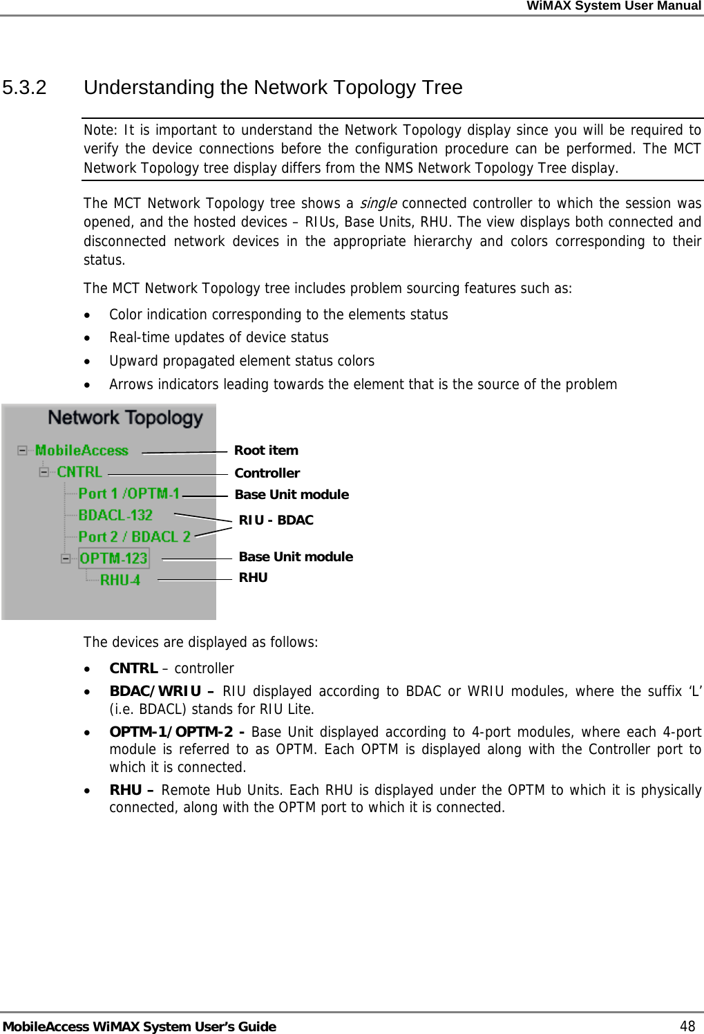
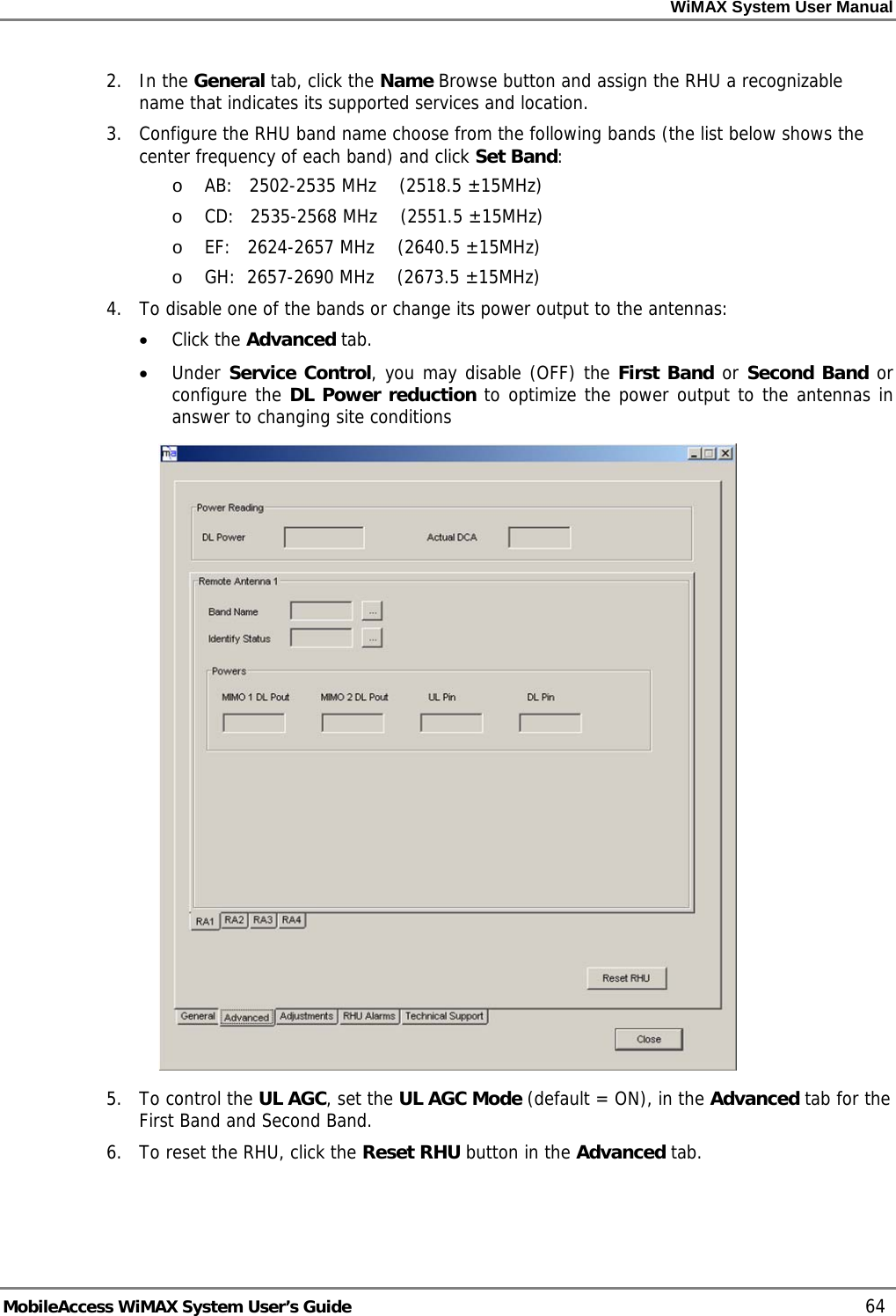
![WiMAX System User Manual MobileAccess WiMAX System User’s Guide 17 Figure 2-1. RIU • The WRIU supports two MIMO bands • WRIU supports RF connection via simplex or duplex connectors (simplex connectors has separate connectors for UL and DL, duplex connectors uses the same connector for both UL and DL) • The WRIU can forward to the OPTM a combination of WiMAX and cellular signals • Attenuation – can be enabled/disabled by the user • The WRIU has a service control switch (enable/disable) for each MIMO (controlled automatically and manually) • Management: RS485 controller interface and RS232 local management connection • Allows remote SW download and upgrade • WRIU can support two SW versions at a time and allows to swap between these two versions • [This bullet and the figure bellow are also at the System Architecture chapter] The new WRIU can support a cellular RIU. The cellular RIU is connected to the WRIU threw a dedicated port. The cellular RIU can support up to 3 BTSC. The WRIU combines the cellular traffic with the WiMAX signals and transmits them together to the BU. At the end, a passive antenna can be connected to the RA in addition to the MIMO1 and MIMO2 antennas. WRIU front panel](https://usermanual.wiki/Corning-Optical-Communication/MA1000WIMAX/User-Guide-1142945-Page-17.png)