Corning Optical Communication MA1000WIMAX ENCOVER 1000 WIMAX DISTRIBUTED ANTENNA SYSTEM User Manual WiMAX Reference Guide 01 JULY 09
Corning Optical Communication Wireless ENCOVER 1000 WIMAX DISTRIBUTED ANTENNA SYSTEM WiMAX Reference Guide 01 JULY 09
Users Manual

P/N: 709C003101
Date: JULY-09
MobileAccess WiMAX System
Preliminary Reference Guide
User Manual


WiMAX System User Manual
MobileAccess WiMAX System User’s Guide III
P
Pr
re
ef
fa
ac
ce
e
M
Ma
at
te
er
ri
ia
al
l
© COPYRIGHT 2008, MOBILEACCESS NETWORKS INC. ALL RIGHTS RESERVED.
MOBILEACCESS™ IS A REGISTERED TRADEMARK OF MOBILEACCESS. THIS DOCUMENT CONTAINS OTHER TRADEMARKS, TRADE NAMES AND
SERVICE MARKS OF MOBILEACCESS AND OTHER ORGANIZATIONS, ALL OF WHICH ARE THE PROPERTY OF THEIR RESPECTIVE OWNERS.
THIS DOCUMENT CONTAINS CONFIDENTIAL AND PROPRIETARY INFORMATION OF MOBILEACCESS AND MAY NOT BE COPIED, TRANSMITTED, STORED
IN A RETRIEVAL SYSTEM OR REPRODUCED IN ANY FORMAT OR MEDIA, IN WHOLE OR IN PART, WITHOUT THE PRIOR WRITTEN CONSENT OF
MOBILEACCESS. INFORMATION CONTAINED IN THIS DOCUMENT SUPERSEDES ANY PREVIOUS MANUALS, GUIDES, SPECIFICATIONS, DATA SHEETS OR
OTHER INFORMATION THAT MAY HAVE BEEN PROVIDED OR MADE AVAILABLE TO THE USER.
THIS DOCUMENT IS PROVIDED FOR INFORMATIONAL PURPOSES ONLY, AND MOBILEACCESS DOES NOT WARRANT OR GUARANTEE THE ACCURACY,
ADEQUACY, QUALITY, VALIDITY, COMPLETENESS OR SUITABILITY FOR ANY PURPOSE OF THE INFORMATION CONTAINED IN THIS DOCUMENT.
MOBILEACCESS RESERVES THE RIGHT TO MAKE UPDATES, IMPROVEMENTS AND ENHANCEMENTS TO THIS DOCUMENT AND THE PRODUCTS TO
WHICH IT RELATES AT ANY TIME WITHOUT PRIOR NOTICE TO THE USER. MOBILEACCESS MAKES NO WARRANTIES, EXPRESS OR
IMPLIED, INCLUDING, WITHOUT LIMITATION, THOSE OF MERCHANTABILITY AND FITNESS FOR A PARTICULAR PURPOSE,
WITH RESPECT TO THIS DOCUMENT OR ANY INFORMATION CONTAINED HEREIN.

WiMAX System User Manual
MobileAccess WiMAX System User’s Guide IV
Policy for Warrantee and Repair
MOBILEACCESS TESTS AND INSPECTS ALL ITS PRODUCTS TO VERIFY THEIR QUALITY AND RELIABILITY. MOBILEACCESS USES EVERY REASONABLE
PRECAUTION TO ENSURE THAT EACH UNIT MEETS THEIR DECLARED SPECIFICATIONS BEFORE SHIPMENT. CUSTOMERS SHOULD ADVISE THEIR
INCOMING INSPECTION, ASSEMBLY, AND TEST PERSONNEL ABOUT THE PRECAUTIONS REQUIRED IN HANDLING AND TESTING OUR PRODUCTS. MANY
OF THESE PRECAUTIONS CAN BE FOUND IN THIS MANUAL.
THE PRODUCTS ARE COVERED BY THE FOLLOWING WARRANTIES:
General Warranty
MOBILEACCESS WARRANTS TO THE ORIGINAL PURCHASER ALL STANDARD PRODUCTS SOLD BY MOBILEACCESS TO BE FREE OF DEFECTS IN
MATERIAL AND WORKMANSHIP FOR ONE (1) YEAR FROM DATE OF SHIPMENT FROM MOBILEACCESS. DURING THE WARRANTY PERIOD,
MOBILEACCESS WILL REPAIR OR REPLACE ANY PRODUCT THAT MOBILEACCESS PROVES TO BE DEFECTIVE. THIS WARRANTY DOES NOT APPLY TO
ANY PRODUCT THAT HAS BEEN SUBJECT TO ALTERATION, ABUSE, IMPROPER INSTALLATION OR APPLICATION, ACCIDENT, ELECTRICAL OR
ENVIRONMENTAL OVER-STRESS, NEGLIGENCE IN USE, STORAGE, TRANSPORTATION OR HANDLING.
Specific Product Warranty Instructions
ALL MOBILEACCESS PRODUCTS ARE WARRANTED AGAINST DEFECTS IN WORKMANSHIP, MATERIALS AND CONSTRUCTION, AND TO NO FURTHER
EXTENT. ANY CLAIM FOR REPAIR OR REPLACEMENT OF UNITS FOUND TO BE DEFECTIVE ON INCOMING INSPECTION BY A CUSTOMER MUST BE MADE
WITHIN 30 DAYS OF RECEIPT OF SHIPMENT, OR WITHIN 30 DAYS OF DISCOVERY OF A DEFECT WITHIN THE WARRANTY PERIOD.
THIS WARRANTY IS THE ONLY WARRANTY MADE BY MOBILEACCESS AND IS IN LIEU OF ALL OTHER WARRANTIES, EXPRESSED OR IMPLIED.
MOBILEACCESS SALES AGENTS OR REPRESENTATIVES ARE NOT AUTHORIZED TO MAKE COMMITMENTS ON WARRANTY RETURNS.
Returns
IN THE EVENT THAT IT IS NECESSARY TO RETURN ANY PRODUCT AGAINST ABOVE WARRANTY, THE FOLLOWING PROCEDURE SHALL BE FOLLOWED:
1. RETURN AUTHORIZATION IS TO BE RECEIVED FROM MOBILEACCESS PRIOR TO RETURNING ANY UNIT. ADVISE MOBILEACCESS OF THE MODEL,
SERIAL NUMBER, AND DISCREPANCY. THE UNIT MAY THEN BE FORWARDED TO MOBILEACCESS, TRANSPORTATION PREPAID. DEVICES RETURNED
COLLECT OR WITHOUT AUTHORIZATION MAY NOT BE ACCEPTED.
2. PRIOR TO REPAIR, MOBILEACCESS WILL ADVISE THE CUSTOMER OF OUR TEST RESULTS AND ANY CHARGES FOR REPAIRING CUSTOMER-CAUSED
PROBLEMS OR OUT-OF-WARRANTY CONDITIONS ETC.
3. REPAIRED PRODUCTS ARE WARRANTED FOR THE BALANCE OF THE ORIGINAL WARRANTY PERIOD, OR AT LEAST 90 DAYS FROM DATE OF
SHIPMENT.
Limitations of Liabilities
MOBILEACCESS'S LIABILITY ON ANY CLAIM, OF ANY KIND, INCLUDING NEGLIGENCE FOR ANY LOSS OR DAMAGE ARISING FROM, CONNECTED WITH,
OR RESULTING FROM THE PURCHASE ORDER, CONTRACT, QUOTATION, OR FROM THE PERFORMANCE OR BREACH THEREOF, OR FROM THE DESIGN,
MANUFACTURE, SALE, DELIVERY, INSTALLATION, INSPECTION, OPERATION OR USE OF ANY EQUIPMENT COVERED BY OR FURNISHED UNDER THIS
CONTACT, SHALL IN NO CASE EXCEED THE PURCHASE PRICE OF THE DEVICE WHICH GIVES RISE TO THE CLAIM.
EXCEPT AS EXPRESSLY PROVIDED HEREIN, MOBILEACCESS MAKES NO WARRANTY, EXPRESSED OR IMPLIED, WITH
RESPECT TO ANY GOODS, PARTS AND SERVICES PROVIDED IN CONNECTION WITH THIS AGREEMENT INCLUDING, BUT NOT
LIMITED TO, THE IMPLIED WARRANTIES OF MERCHANTABILITY AND FITNESS FOR A PARTICULAR PURPOSE. MOBILEACCESS
SHALL NOT BE LIABLE FOR ANY OTHER DAMAGE INCLUDING, BUT NOT LIMITED TO, INDIRECT, SPECIAL OR CONSEQUENTIAL
DAMAGES ARISING OUT OF OR IN CONNECTION WITH FURNISHING OF GOODS, PARTS AND SERVICE HEREUNDER, OR THE
PERFORMANCE, USE OF, OR INABILITY TO USE THE GOODS, PARTS AND SERVICE.

WiMAX System User Manual
MobileAccess WiMAX System User’s Guide V
Reporting Defects
THE UNITS WERE INSPECTED BEFORE SHIPMENT AND FOUND TO BE FREE OF MECHANICAL AND ELECTRICAL DEFECTS.
EXAMINE THE UNITS FOR ANY DAMAGE THAT MAY HAVE BEEN CAUSED IN TRANSIT. IF DAMAGE IS DISCOVERED, FILE A CLAIM WITH THE FREIGHT
CARRIER IMMEDIATELY. NOTIFY MOBILEACCESS AS SOON AS POSSIBLE.
NOTE: KEEP ALL PACKING MATERIAL UNTIL YOU HAVE COMPLETED THE INSPECTION
WARNING: TO COMPLY WITH FCC RF EXPOSURE COMPLIANCE REQUIREMENTS, ANTENNAS USED FOR THIS PRODUCT MUST BE FIXED MOUNTED
ON INDOOR PERMANENT STRUCTURES, PROVIDING A SEPARATION DISTANCE OF AT LEAST 20 CM FROM ALL PERSONS DURING NORMAL OPERATION.
WARNING: ANTENNA GAIN SHOULD NOT EXCEED 10 DB.
WARNING: EACH INDIVIDUAL ANTENNA USED FOR THIS TRANSMITTER MUST BE INSTALLED TO PROVIDE A MINIMUM SEPARATION DISTANCE OF 20
CM OR MORE FROM ALL PERSONS AND MUST NOT BE CO-LOCATED WITH ANY OTHER ANTENNA FOR MEETING RF EXPOSURE REQUIREMENTS.
WARNING: THE DESIGN OF THE ANTENNA INSTALLATION NEEDS TO BE IMPLEMENTED IN SUCH A WAY SO AS TO ENSURE RF RADIATION SAFETY
LEVELS AND NON-ENVIRONMENTAL POLLUTION DURING OPERATION.
ATTENTION:
COMPLIANCE WITH RF SAFETY REQUIREMENTS:
MOBILEACCESS™ PRODUCTS HAVE NO INHERENT SIGNIFICANT RF RADIATION.
Laser Safety
FIBER OPTIC PORTS OF THE MOBILEACCESS WIMAX-RU-GECH-4 EMIT INVISIBLE LASER RADIATION AT THE 1310 NM WAVELENGTH WINDOW.
TO AVOID EYE INJURY NEVER LOOK DIRECTLY INTO THE OPTICAL PORTS, PATCHCORDS OR OPTICAL CABLES. DO NOT STARE INTO BEAM OR VIEW
DIRECTLY WITH OPTICAL INSTRUMENTS. ALWAYS ASSUME THAT OPTICAL OUTPUTS ARE ON.
ONLY TECHNICIANS FAMILIAR WITH FIBER OPTIC SAFETY PRACTICES AND PROCEDURES SHOULD PERFORM OPTICAL FIBER CONNECTIONS AND
DISCONNECTIONS OF THE WIMAX-RU-GECH-4 DEVICES AND THE ASSOCIATED CABLES.
THE WIMAX-RU-GECH-4 COMPLIES WITH 21 CFR 1040.10 AND 1040.11 EXCEPT FOR DEVIATIONS PURSUANT TO LASER NOTICE NO. 50 (JULY
26, 2001) & IEC 60825-1, AMENDMENT 2 (JAN. 2001).

WiMAX System User Manual
MobileAccess WiMAX System User’s Guide VI
Standards and Certification
FCC CODE FRC47 part 27
About This Guide
This guide provides all the information required to install, configure and monitor the WiMAX
System.
Revision History
The revision history for this document is shown in Table
1-1.
Table
1-1: Revision history
P/N Date Description
709C003101 JUNE-09 Initial version
Additional Documents
The following table lists additional documents required for the operation of the system.
Table
1-2: Additional Documents
Name
MA WiMAX NMS System Installation and Configuration Guide.

WiMAX System User Manual
MobileAccess WiMAX System User’s Guide VII
Table of Contents
Preface Material .........................................................................................................................III
Policy for Warrantee and Repair.......................................................................................................IV
Laser Safety...................................................................................................................................V
Standards and Certification..............................................................................................................VI
About This Guide............................................................................................................................VI
Revision History..............................................................................................................................VI
Additional Documents......................................................................................................................VI
Table of Contents ..........................................................................................................................VII
1 Introduction to MA WiMAX System..................................................................................10
1.1 System Architecture................................................................................................................ 12
1.2 WiMAX Standalone Solution – Basic System Operation ............................................................... 13
1.3 WiMAX Overlay Solution ..........................................................................................................14
1.4 Converged Cellular-WiMAX system............................................................................................ 15
1.5 Commissioning and Control...................................................................................................... 15
2 System Elements ...............................................................................................................16
2.1 WiMAX Front-end Elements...................................................................................................... 16
2.1.1 WiMAX RIU ................................................................................................................... 16
2.1.1.1 RIU Front Panel................................................................................................. 19
2.1.1.2 RIU Rear Panel..................................................................................................20
2.1.2 MA Multi-Service BUs ..................................................................................................... 20
2.1.2.1 BU Front Panel .................................................................................................. 20
2.1.2.2 BU Rear Panel ................................................................................................... 22
2.1.3 MA 410 Controllers ........................................................................................................ 22
2.1.3.1 Front-Panel Description...................................................................................... 23
2.1.3.2 Rear Panel Description ....................................................................................... 24
2.1.3.3 Controller LCD Fault Indications.......................................................................... 24
2.2 WiMAX Remote End Elements.................................................................................................. 25
2.2.1 WiMAX Remote Hub Unit................................................................................................ 25
2.2.2 Remote Antenna Unit..................................................................................................... 27
2.2.2.1 Remote Antenna Unit Front Panel........................................................................ 28

WiMAX System User Manual
MobileAccess WiMAX System User’s Guide VIII
3 Installation..........................................................................................................................29
3.1 Communication Room Installation ............................................................................................ 30
3.1.1.1 Front View ........................................................................................................ 30
3.1.1.2 Rear View Connections....................................................................................... 31
3.2 Remote Site Installation........................................................................................................... 32
3.2.1.1 Front View Connections...................................................................................... 32
4 Setup and Commissioning Procedure.............................................................................33
4.1 Overview................................................................................................................................ 33
4.2 Requirements......................................................................................................................... 33
4.3 General Checks....................................................................................................................... 33
4.3.1 Verify Connections......................................................................................................... 34
4.3.2 Set Up MCT Monitoring .................................................................................................. 35
4.3.3 Verify the Controller Clock Settings.................................................................................. 35
4.3.4 Verify End-to-End Link in Topology Tree.......................................................................... 36
4.3.5 Set the Base Line........................................................................................................... 37
4.3.6 Verify End Units Optical Signal and Service Band.............................................................. 37
4.3.7 Name the BUs, RHUs and RIUs....................................................................................... 38
4.4 Adjustment Procedure............................................................................................................. 38
5 Using MCT ..........................................................................................................................42
5.1 General.................................................................................................................................. 42
5.2 Getting Started....................................................................................................................... 43
5.2.1 Serial Connection and Login............................................................................................ 43
5.2.2 Dial-up Modem Connection and Login.............................................................................. 44
5.3 Navigating the MCT Application................................................................................................ 46
5.3.1 Menu Bar......................................................................................................................47
5.3.2 Understanding the Network Topology Tree ...................................................................... 48
5.3.2.1 When and how are devices displayed in the tree?................................................. 49
5.3.2.2 Tree Status Colors ............................................................................................. 49
5.3.2.3 Invoking configuration dialogs from the Topology tree.......................................... 50
5.3.3 Device View Pane.......................................................................................................... 51
5.3.4 About Device Configuration Dialogs................................................................................. 52
5.4 Authorization Levels and Passwords.......................................................................................... 53
5.5 Configuration Overview ........................................................................................................... 54
5.6 Controller Configuration........................................................................................................... 54
5.6.1 Configuring Controller System Parameters ....................................................................... 55
5.6.2 Configuring Auxiliary Devices.......................................................................................... 56

WiMAX System User Manual
MobileAccess WiMAX System User’s Guide IX
5.7 Configuring MobileAccess Devices............................................................................................. 57
5.7.1 Configuring for a MobileAccess Device Hosting................................................................. 57
5.7.2 Adding a New MobileAccess Device ................................................................................. 58
5.7.3 WIMAX (WRIU) RIU Configuration and Control................................................................. 59
5.7.4 OPTM (BU) Configuration Dialog ..................................................................................... 61
5.7.5 RHU Configuration Dialog............................................................................................... 63
5.8 Configuring for Legacy Devices ................................................................................................ 65
5.9 Reviewing the Inventory Reports............................................................................................. 67
5.10 What Next?............................................................................................................................ 68
1 I
In
nt
tr
ro
od
du
uc
ct
ti
io
on
n
t
to
o
M
MA
A
W
Wi
iM
MA
AX
X
S
Sy
ys
st
te
em
m
MobileAccess WiMAX Indoor Coverage Solution provides a complete, cost effective, scalable
indoor coverage solution for up to two MIMO WiMAX.
The MA-WiMAX solution enables distributing signals from a WiMAX BTS located at a central
location over fiber optic connections to remote locations (different floors or areas) throughout
the building infrastructure.
The solution can be used as stand-alone - providing only WiMAX coverage via a dedicated
antenna infrastructure, or in conjunction with MA-1000 or MA-2000 MobileAccess systems –
combining WiMAX with other wireless services for distribution over a common antenna
infrastructure.
MA WiMAX system provides a truly integrated solution offering a combined services approach to
distribute WiMAX and cellular/PCS through a single antenna infrastructure while maintaining a
reliable application independent environment.
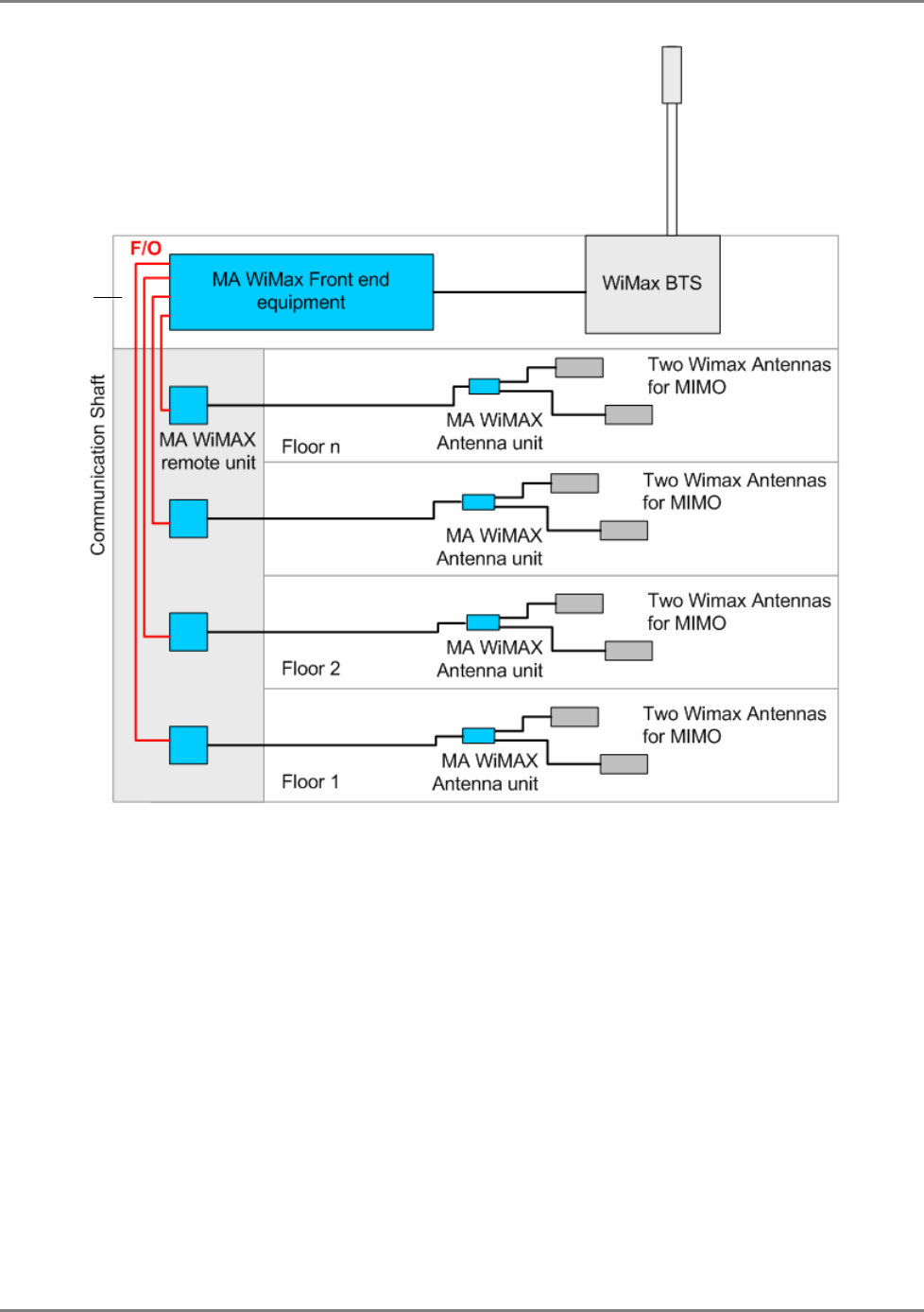
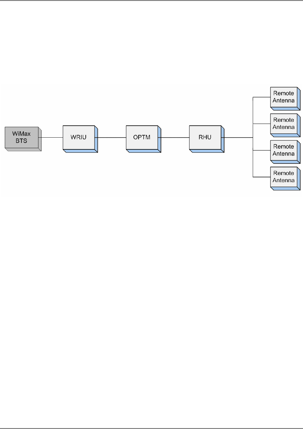
The following block diagram illustrates the stand-alone MA WiMAX solution elements: the MA
WiMAX front end equipment is installed near the WiMAX BTS. In the downlink, it conditions the
signal and converts it to fiber optic for transmission to each remote site over the optic fiber. At
each remote site it is reconverted to RF and distributed by two WiMAX antennas.
Each MA WiMAX element is set up and monitored through a local connection from a computer
running the MCT application.
WiMAX System User Manual
MobileAccess WiMAX System User’s Guide 11
Figure 1. MA WiMAX System Architecture
Roof

WiMAX System User Manual
MobileAccess WiMAX System User’s Guide 12
Features and Capabilities
• Supports two WiMAX MIMO
• Scalable: Easily expands as needed to cover several million square feet
• Enterprise Value: Solution is easily integrated with other wireless applications – opportunity
to amortize deployment costs
• Reduced Barrier to Entry: Modular design enables pay-as-you-grow model – add sectors and
components as needed
• End-to-end Management: Proactive management and control maximizes uptime
• Local and remote end-to-end monitoring and control through interface to MA 410 controllers
• Monitoring at the head-end through interface to MA-RIU
1.1 System Architecture
The system is based on front-end elements that condition and convert the BTS WiMAX signal to
an optic signal for transmission over single mode fiber optics to the head-end elements, and on
head-end elements that reconvert the WiMAX optic signal to RF and distribute it over the
antenna infrastructure at that location. In addition, Controllers located at the front-end provide
end-to-end remote control and management.
The MA WiMAX system can be converged with another MA mobile service indoor distribution
systems (such as MA2000, MA1000, etc.), where the systems run in parallel and share some of
the same front-end elements and the antenna infrastructure.
The MA WiMAX system front end elements are:
• MA WiMAX RIU – conditions the RF signal from the BTS to the level required by the Base
Unit. Each RIU supports two WiMAX channels (for MIMO) and two base 4 units (for 8 remote
units). See section 2.1.1 for unit description.
• MA Multi-service Base Unit – converts the WIMAX channels to optic signal for transmission
over one set of optical fibers. See section 2.1.2 for unit description.
• MA 410 controller – provides management and control functions to all system elements. The
Controller is directly connected to the RIU modules and to the BUs. See section 2.1.3 for unit
description.
Note: The RIU, Base Units and Controller are located at the head-end (i.e. communication room).
The WiMAX systems remote location elements are:
• WiMAX RHU – located at each remote location, IDF or telecom closet. Performs the optic to
RF conversion of the WiMAX signals and provides the interface (power and communications)
to the remote antenna unit (RU) via which the signals are distributed. See section 2.2.1 for
unit description.
• Remote Antenna Unit (RA) – provides final preparation of the WIMAX signals for distribution
via the ceiling antenna(s). The RU has three antenna ports to support 2 MIMOs and one
passive cellular antenna. See section 2.2.2 for unit description.
WiMAX System User Manual
MobileAccess WiMAX System User’s Guide 13
1.2 WiMAX Standalone Solution – Basic System
Operation
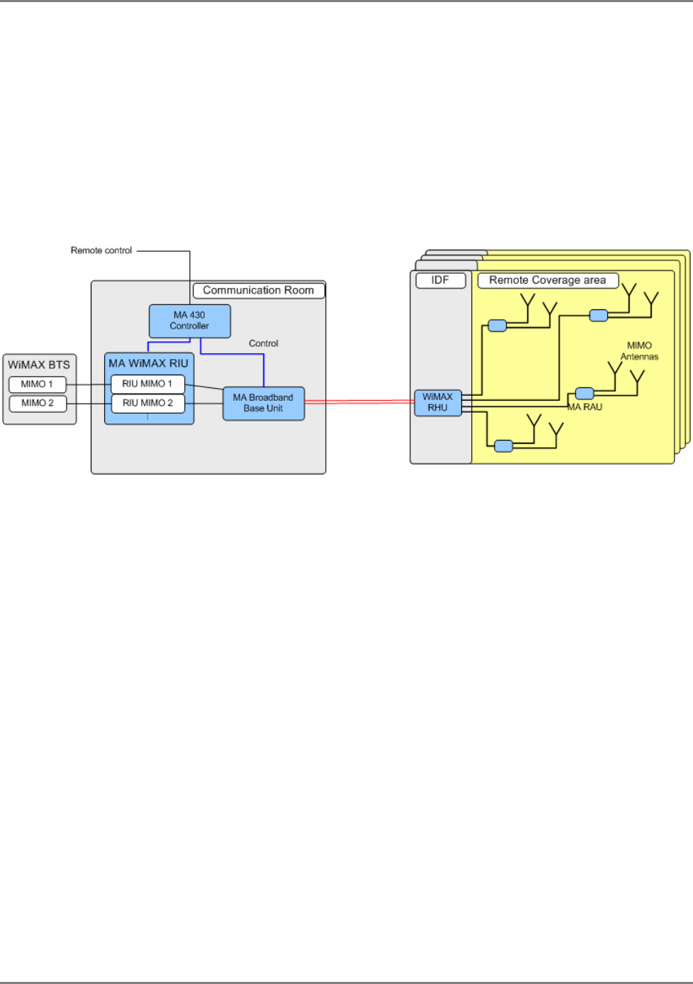
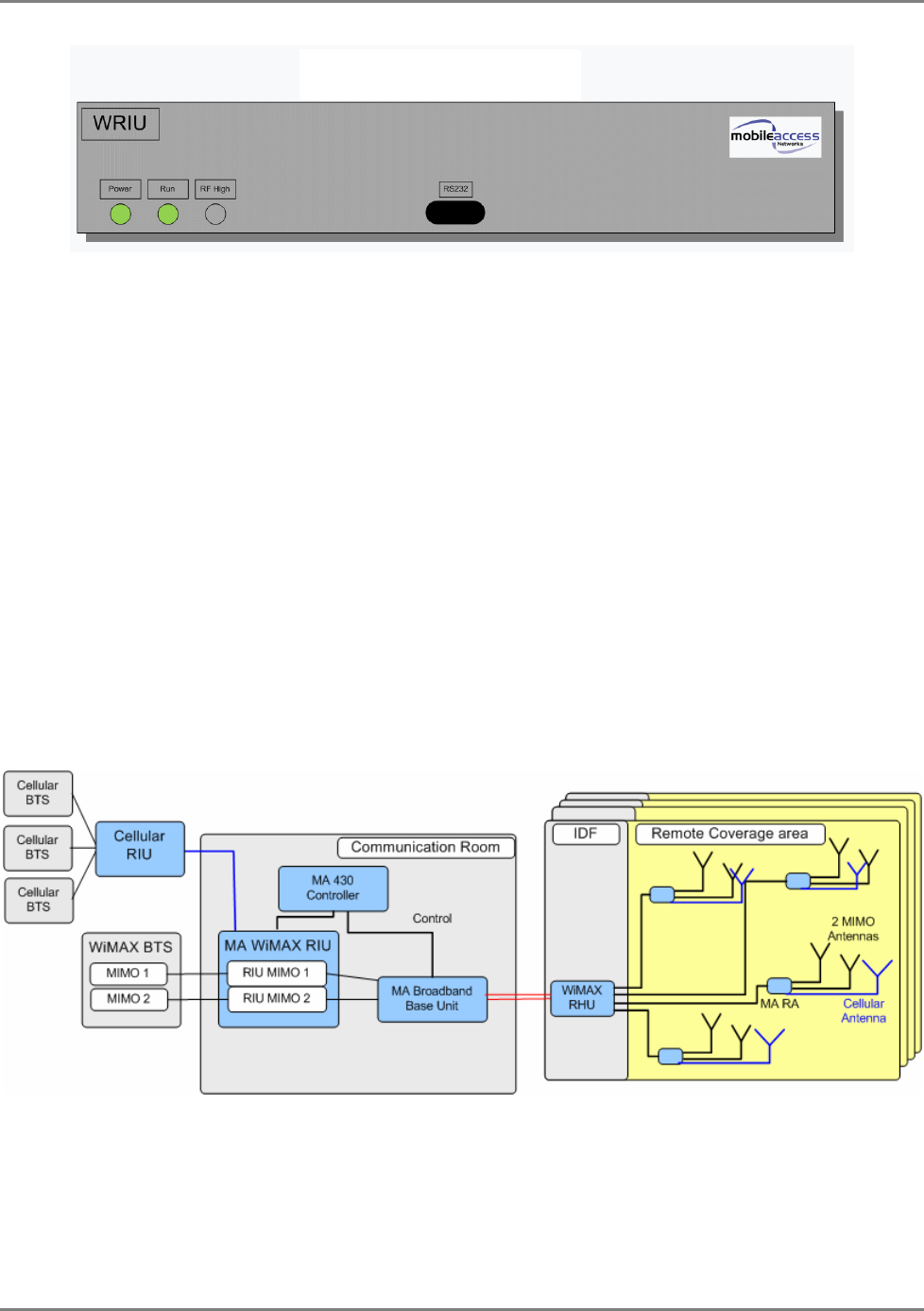
Figure 1-2 shows the architecture of a stand-alone MA WiMAX system. The WiMAX system
receives the services from the operator’s BTS converts them to an optical signal and runs them
over optic fiber to each remote location. There, the WiMAX RHU reconverts the services to RF
and distributes them to WiMAX antennas via the MA Remote Antenna Unit. The latter provides
remote control and management to the passive WiMAX antennas.
Figure 1-2. Architecture of a basic MA WiMAX system
WiMAX System User Manual
MobileAccess WiMAX System User’s Guide 14
1.3 WiMAX Overlay Solution
Overlay with Cellular and WiMAX.
Figure-
1-3
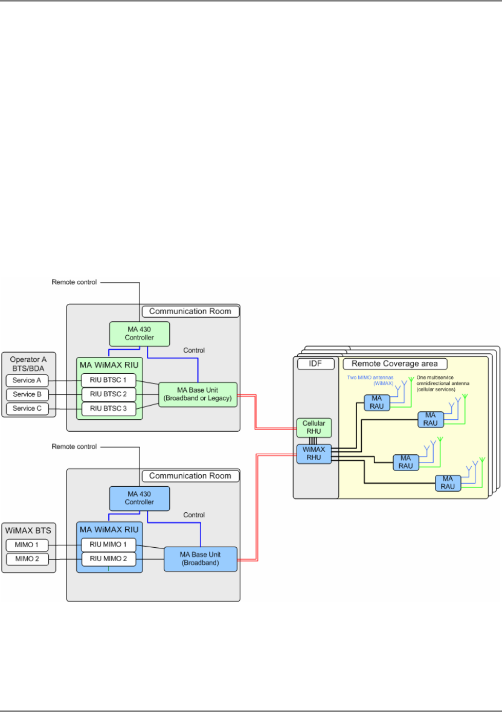
shows the architecture of an installation supporting the indoor distribution of WiMAX,
together with cellular services over a common coax and antenna infrastructure.
The figure shows two systems running in parallel: Cellular system along side of a WiMAX system
(at the bottom). Both systems received the services from the operator’s BTS or BDA, convert
them to an optical signal and run them over optic fiber to each remote location. There, the
cellular RHU reconverts the cellular services to RF and the WiMAX RHU converges the cellular
and WiMAX services and distributes them to the WiMAX and cellular antennas via the MA
Remote Antenna Unit. The latter provides remote control and management to the passive
WiMAX and cellular antennas.
Figure-
1-3 –Architecture of MA WiMAX System Converged with MA 1000 System Services
WiMAX System User Manual
MobileAccess WiMAX System User’s Guide 15
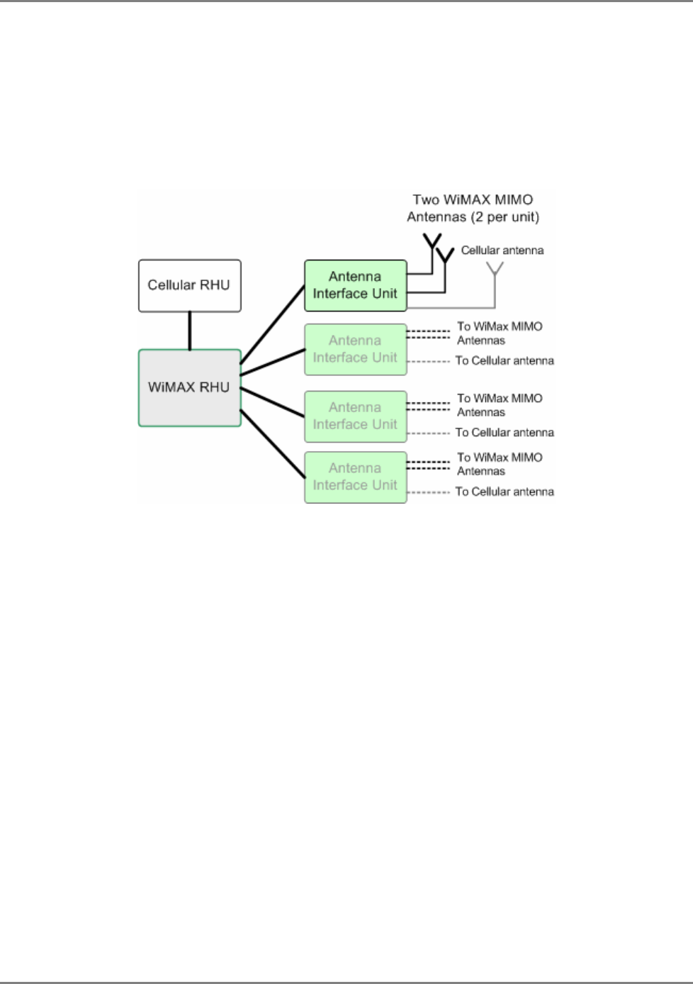
1.4 Converged Cellular-WiMAX system
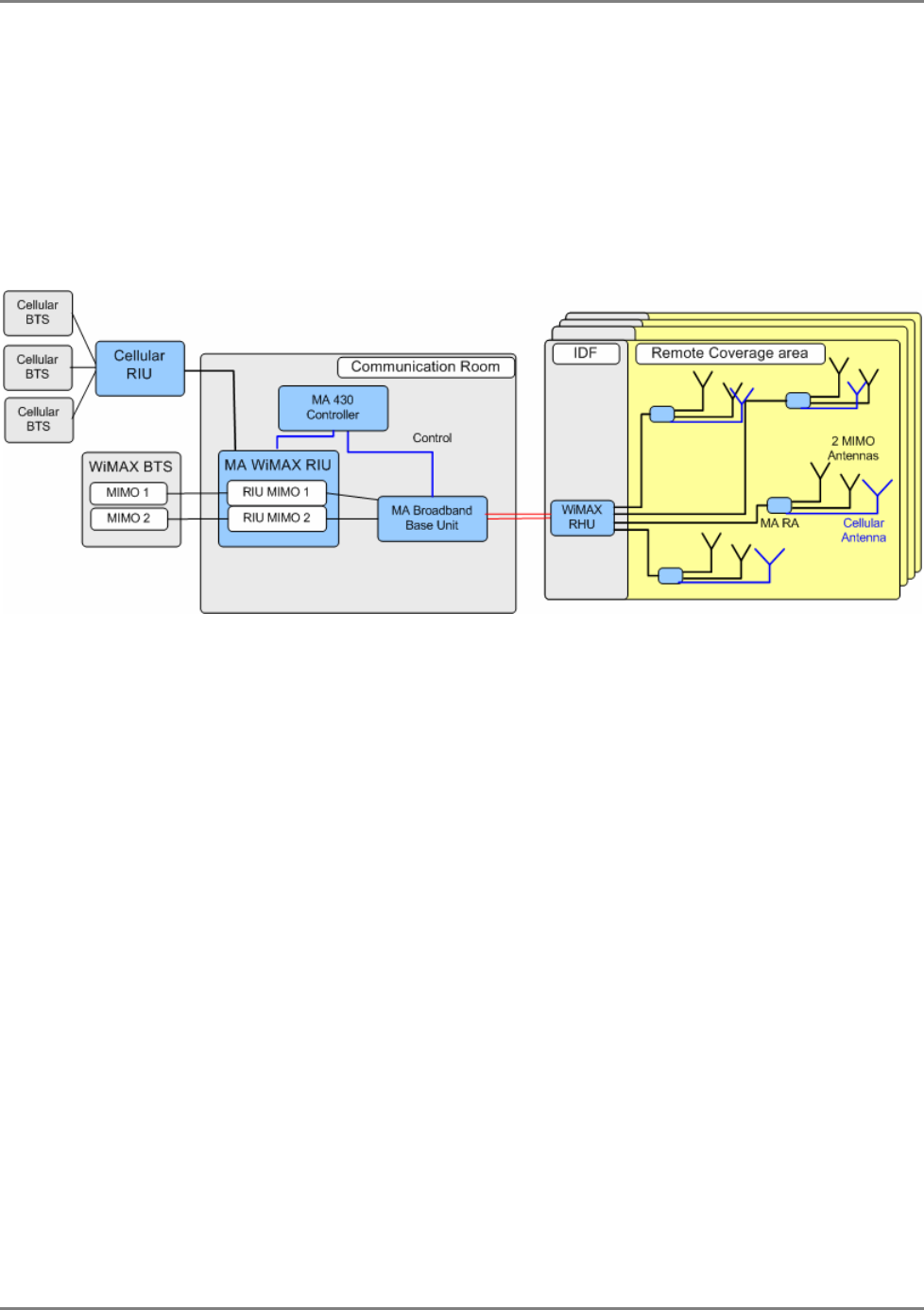
The WRIU can support a cellular RIU. The cellular RIU is connected to the WRIU threw a
dedicated port. The cellular RIU can support up to 3 BTSC. The WRIU combines the cellular
traffic with the WiMAX signals and transmits them together to the BU. At the end, a passive
antenna can be connected to the RA in addition to the MIMO1 and MIMO2 antennas.
Figure 1-4. Architecture of a converged Cellular-WiMAX system
1.5 Commissioning and Control
The current version of the system is configured and managed via a local connection from a
computer running the MA MCT application. See
Chapter-
4 .
WiMAX System User Manual
MobileAccess WiMAX System User’s Guide 16
2 S
Sy
ys
st
te
em
m
E
El
le
em
me
en
nt
ts
s
This chapter provides detailed descriptions of the system elements, panels and connections.
2.1 WiMAX Front-end Elements
These elements are installed in the communication room, close to the WiMAX BTS. The WiMAX
front-end elements are:
• WiMAX RIU
• WiMAX BU
• MA 410 Controller
2.1.1 WiMAX RIU
• 1U 19” rack-mountable chassis
• Duplex connections for each BTS
• Supports two 4-port BUs
• Monitoring via MCT
WiMAX System User Manual
MobileAccess WiMAX System User’s Guide 17
Figure 2-1. RIU
• The WRIU supports two MIMO bands
• WRIU supports RF connection via simplex or duplex connectors (simplex connectors has
separate connectors for UL and DL, duplex connectors uses the same connector for both UL
and DL)
• The WRIU can forward to the OPTM a combination of WiMAX and cellular signals
• Attenuation – can be enabled/disabled by the user
• The WRIU has a service control switch (enable/disable) for each MIMO (controlled
automatically and manually)
• Management: RS485 controller interface and RS232 local management connection
• Allows remote SW download and upgrade
• WRIU can support two SW versions at a time and allows to swap between these two
versions
• [This bullet and the figure bellow are also at the System Architecture chapter] The new
WRIU can support a cellular RIU. The cellular RIU is connected to the WRIU threw a
dedicated port. The cellular RIU can support up to 3 BTSC. The WRIU combines the cellular
traffic with the WiMAX signals and transmits them together to the BU. At the end, a passive
antenna can be connected to the RA in addition to the MIMO1 and MIMO2 antennas.
WRIU front panel

WiMAX System User Manual
MobileAccess WiMAX System User’s Guide 18
Adjustment procedure – the following table describes the adjustment procedure expected power
rates :
Unit Expected input power Output power after successful
adjustment
WRIU from BTS = 0 dbm 20dbm
OPTM from WRIU = -20 dbm after ATE = -43dbm
RHU from OPTM = -43 dbm 0 dbm
RA from RHU = -7 dbm (expected
7db loss on coax) 20dbm
* Performing adjustment procedure only for the WRIU unit interferes with the service
Set Band Wizard
• Display a list of all connected elements (WRIU, RHU, RA)
• Current band of each MIMO is displayed
• Allowed bands for each MIMO are displayed
• The wizard will distribute the new selected band to the RHU (RA should be changed
manually). At the end of he process a ‘success’ or ‘fail’ message will appear.
• Clicking cancel button stops the operation
• AGC mechanism supported (similar to the cellular-RIU)
Alarms:
MIMO – RF power low/high, synthesizer lock/unlock, service OFF/ON, Adj. success/fail, Pilot (freq.)
missing/exist, Adj. source missing/exist,
WiMAX System User Manual
MobileAccess WiMAX System User’s Guide 19
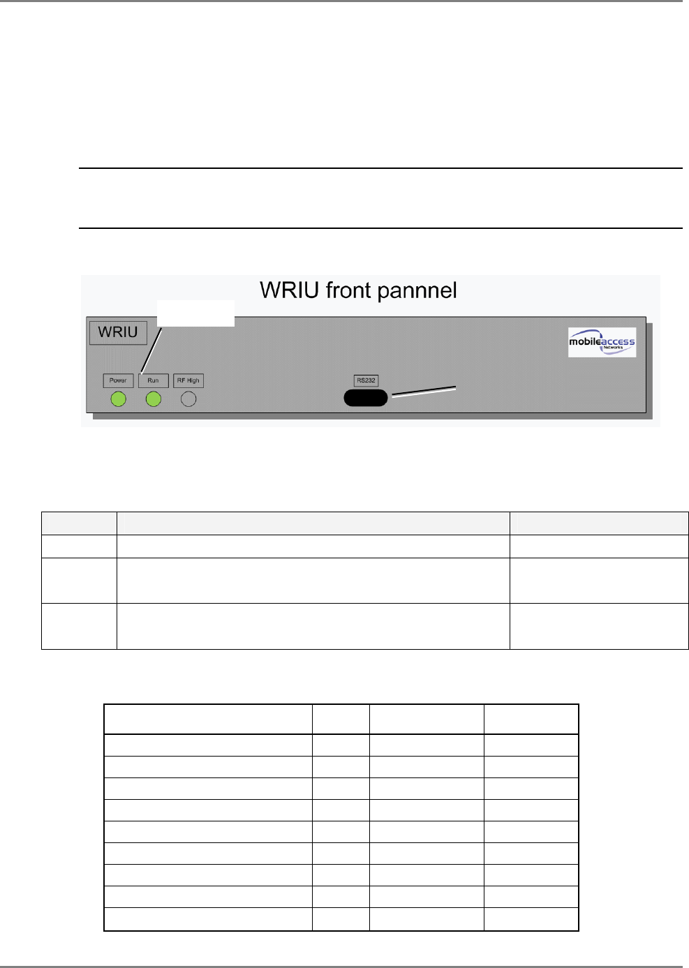
2.1.1.1 RIU Front Panel
The RIU front panel contains the LED indicators, an interface for connections to additional Base
Units and an RS232 service connection. The following figure shows the front panel and the
location of each module.
Note: The UL and DL SMA front panel connections, between the modules, are not shown for
clarity. The device is supplied with the connections already implemented.
They are not to be
modified.
Figure 2-2. RIU Front Panel
Table 2-1. RIU Front Panel Indicators
LED Description Indications
PWR ON – input power is within the required range Steady green - ON
RUN Green Flashing – corresponding RIU module is operational Blinking green – OK
Blinking red – not OK
OVER
POWER Lights on only when the status is “RF high” Steady Red - RF high
Off – RF is not high
The following table describes all the optional statuses of the LEDs:
WRIU status Power
LED Run LED RF High LED
Powered off Off Off Off
No alert – normal status On Blinking green Off
RF low On Blinking red Off
RF high On Blinking red Steady red
Adj. Fail On Blinking red Off
Pilot missing On Blinking red Off
MIMO Synth. Unlock On Blinking red Off
Adjustment source missing On Blinking red Off
Service Off On Blinking red Off
RS232 Setup
connector
Status LEDs
WiMAX System User Manual
MobileAccess WiMAX System User’s Guide 20
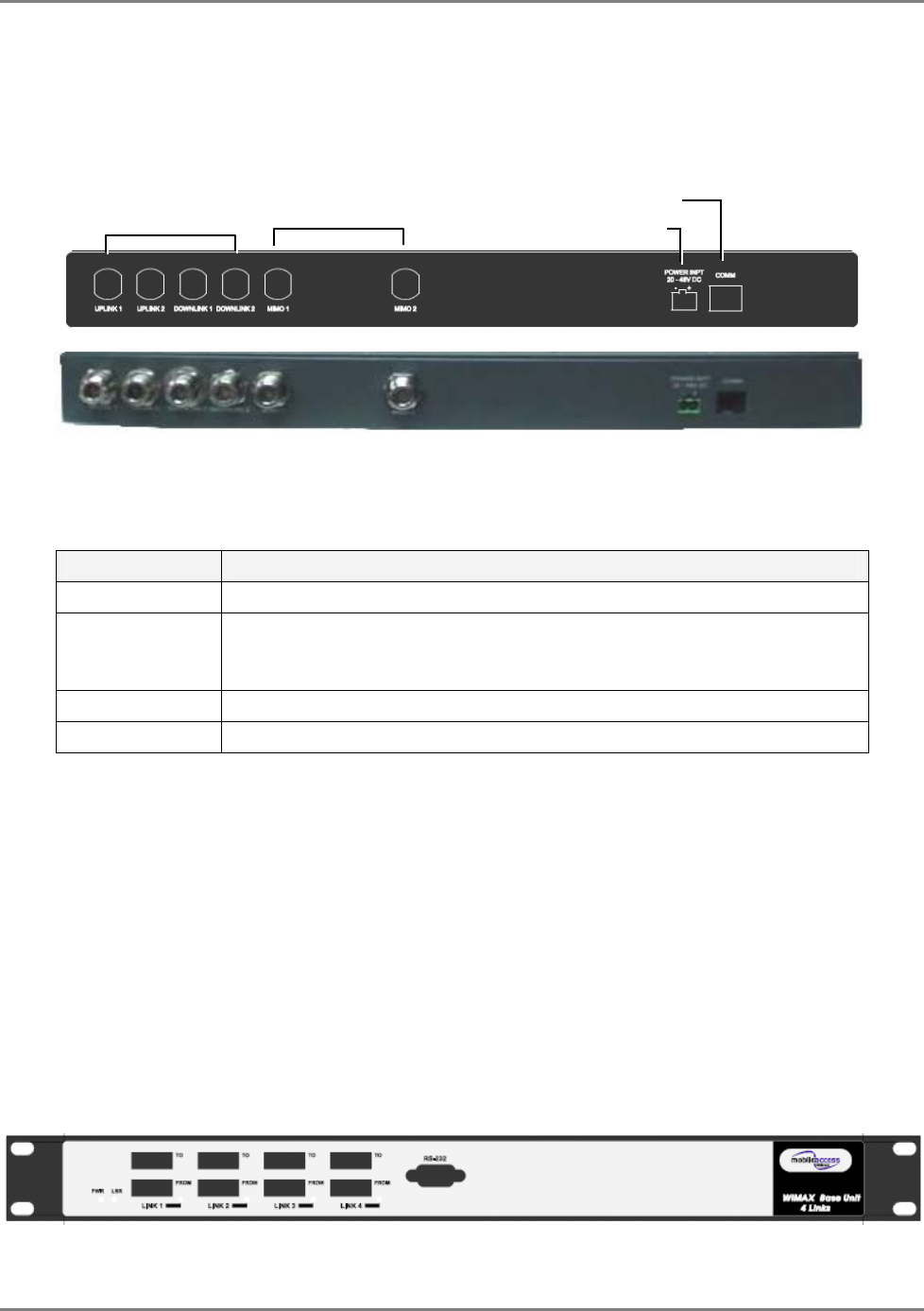
2.1.1.2 RIU Rear Panel
The RIU rear-panel contains the RF, control and power connections.
Figure 2-3. RIU Rear Panel showing the RF Connection
Table 2-2. RIU Rear Panel Connectors
Connector Description
MIMO 1 / MIMO 2 Duplex connections to MIMO 1 and MIMO 2 on BTS side.
UPLINK 1/2
DOWNLINK 1/2 Connections to two 4-port WiMAX BUs. Each pair of UL/DL connections
(i.e. Uplink 1 and Downlink 1) connects to the corresponding RF
connections on a Base Unit.
COM Connections to MA 410 controller rear panel RS485 connector.
Power DC power connection: 20 to 48 VDC
2.1.2 MA Multi-Service BUs
The BUs (Base Units) perform RF to optical conversion of the signal on the side of the operator’s
interface equipment. The BU is connected to the RUs through optic connections and to the RIU
through UL coax connections. Each 4-port BU supports up to four WiMAX RHUs.
The BU (and all the corresponding remote hub units - RHUs) may be monitored and managed
via the MCT.
2.1.2.1 BU Front Panel
The WiMAX BU front panel contains the optical connections and service connection port.
Figure 2-4. 4-Port MA BU Front Panel
Four ports and corresponding indicators
BU Connections RF INPUT 1 and 2 PWR connection
T
o 410 controller

WiMAX System User Manual
MobileAccess WiMAX System User’s Guide 21
Table
2-3. MA BU Front Panel Indicators
LED Description
PWR Power input detected for the corresponding unit.
LSR ON - laser circuitry for the corresponding element (group of four ports)
is functioning correctly.
Link 1-4, 5-8 ON - the optical link from the connected remote is within the
specifications.
Blinking - optical power from remote is lower than minimum level.

WiMAX System User Manual
MobileAccess WiMAX System User’s Guide 22
2.1.2.2 BU Rear Panel
The BU rear panel contains the RF, Alarms, controller and power connections.
Figure 2-5. MA BU Rear Panel
Table
2-4. MobileAccess BU Rear Panel Connections
Connector Description
Uplink output Uplink connection to RIU.
Downlink input Downlink connection to RIU.
Com Port RS485 Connection to MobileAccess 410 controller RS485 port.
PWR Power connection. 20 to 48VDC
Alarms N/A
2.1.3 MA 410 Controllers
Note: This section provides general information on the MobileAccess 410 Controller. For detailed
information on the controller, configuration and connections refer to the Mobile Access NMS
User’s Guide.
The MobileAccess 410 controllers enable managing and controlling the MobileAccess system
elements through Point-to-point connectivity implemented via either direct RS232 connection or
via connection to a PSTN phone line
WiMAX System User Manual
MobileAccess WiMAX System User’s Guide 23
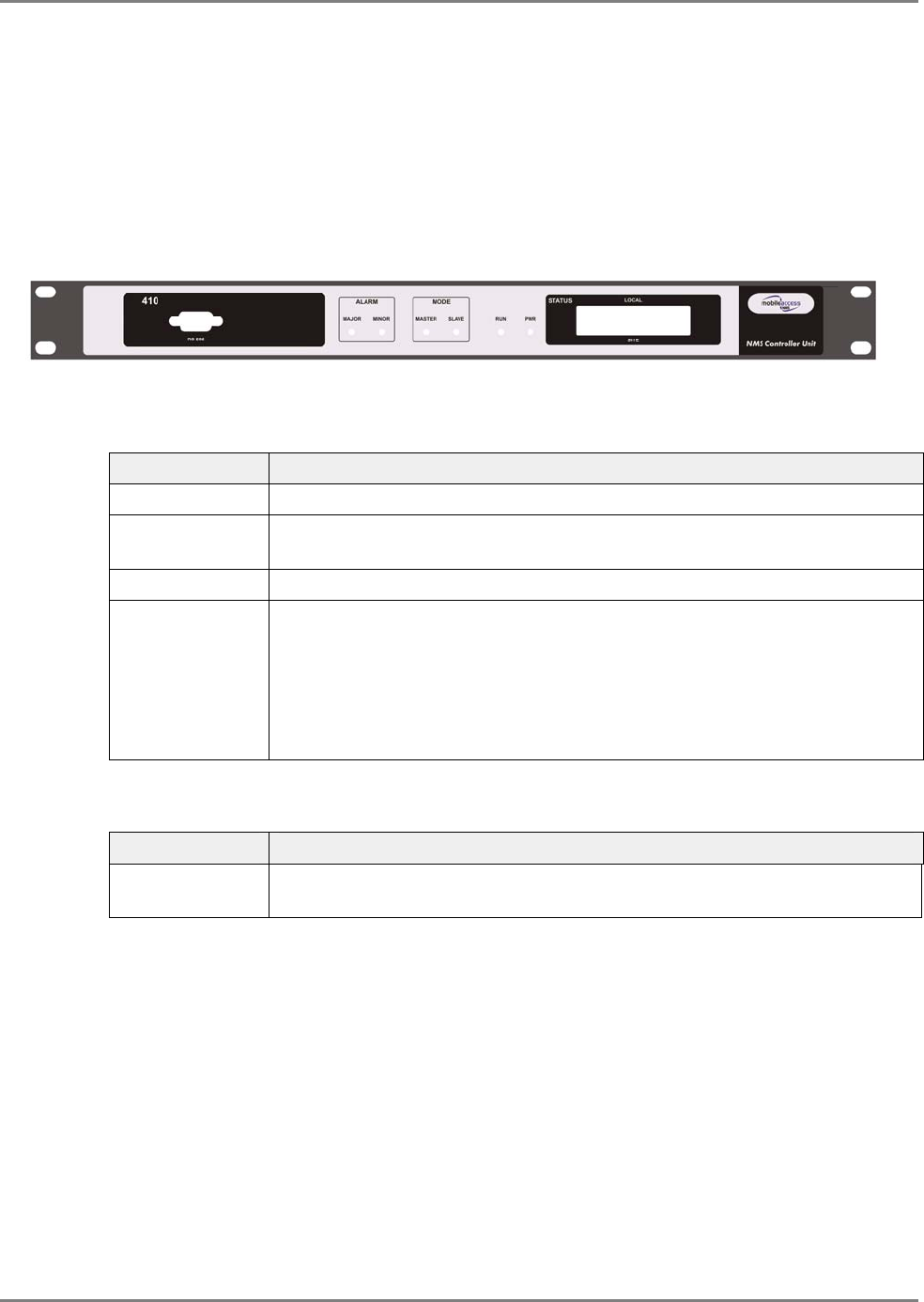
2.1.3.1 Front-Panel Description
The front panel contains the RS232 and TCP/IP management connection ports, the monitoring
and status LEDs, and LCD displays.
Figure 2-6 shows the MA 410 front panel. Table
2-5. MA 410 LED Indicators, describes the LED
indicators.
Figure 2-6. MobileAccess 410 Front Panel
Table
2-5. MA 410 LED Indicators
LED Description
PWR ON green - indicates correct power level
Run ON green - flickers continuously indicating the controller is initialized and
running.
Mode Not relevant.
Failure Indicates whether the alarm is ‘Major’ or ‘Minor’ type of alarms:
Minor red – indicates a single faulty RHU in a building with more than one
RHU
Major red – indicates faulty RHU in a single RHU site, more than one faulty
RHU in a site with multiple RUs, fault on any of the auxiliary inputs, or other
faults.
Table
2-6. MA 410 Front Panel Connectors
Connector Description
RS232 Used for setting up the network parameters (IP Address, community
names, etc.) and for MCT (MA Configuration Tool) connection.
WiMAX System User Manual
MobileAccess WiMAX System User’s Guide 24
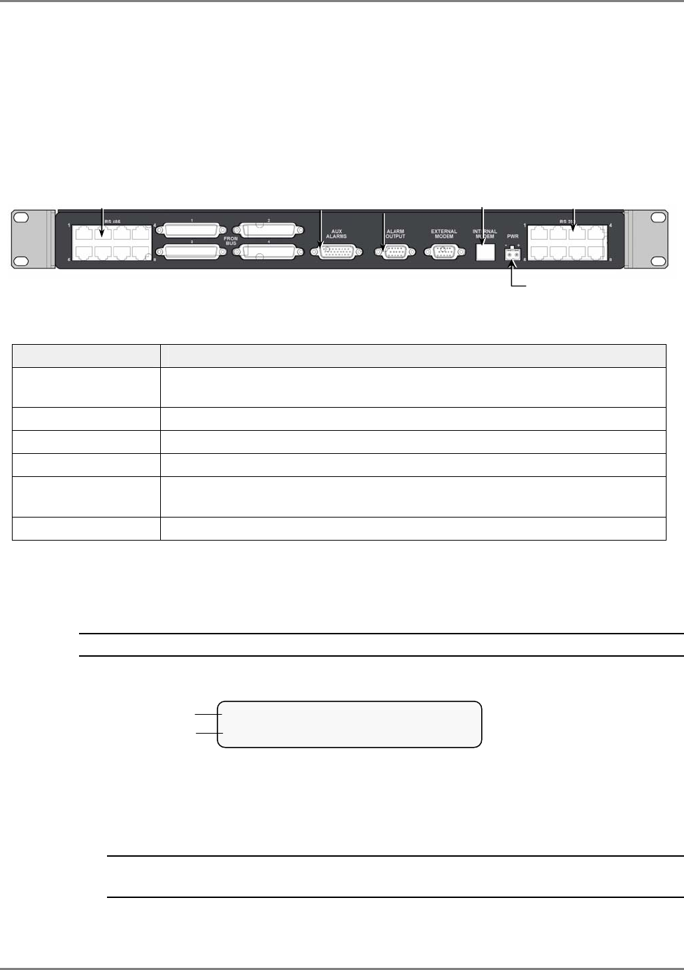
2.1.3.2 Rear Panel Description
The rear-panels of the controllers provide all the connections to the system elements (BUs,
RIUs), dial-up MCT connection, dry-contact auxiliary inputs, auxiliary outputs (to Base Station or
repeater) and power.
The controller rear panel connections are described below.
Figure
2-7. MobileAccess Controller Rear Panel
Connector Description
RS485 MobileAccess Base Units and RIU connections to any of the ports in any
combination.
Auxiliary Alarms Eight inputs for alarms from auxiliary devices
Alarm Output BTS/repeater dry-contact alarms. NMS-BTS/DB15-open cables
External Modem Future option. Connection to an external wireless or dial-up modem.
Internal Modem Used for dial-up connection to the controller for the purpose of MCT
configuration and MCT monitoring.
PWR DC power input: 20 to 48VDC, 0.5A max
2.1.3.3 Controller LCD Fault Indications
The LCD display corresponds to the Major/Minor LEDs.
Note: The display shows two rows; however, only the upper row is relevant.
Following is an example of a display:
Upper row – shows status of locally connected devices, where status is indicated by the
following messages:
• lcl aux major (auxiliary faults are always major), or
• lcl rhu major/minor
Note: if both types of problems were identified, the display toggles between the two
messages.
Power
Not relevant
Phone line
connection
Alarm
Out
p
uts
Alarm
Inputs
MA BUs and RIUs
L C L A U X M a j o r
x _ x _ _ x _ x
Upper row
Not relevant
WiMAX System User Manual
MobileAccess WiMAX System User’s Guide 25
2.2 WiMAX Remote End Elements
2.2.1 WiMAX Remote Hub Unit
MA WiMAX RHU is
installed in the shaft of each head-end location
. It provides the following
functions:
• Optical to RF for downlink signals and RF to Optical for uplink signals
• Interfaces to Remote Antenna Units (RA) – via on one side and to the optic fiber from the
Base Units on the other side
• Connects (via Remote Antenna Units) to MA omni-directional multi-service antennas through
coax cables and to the host WiMAX BU (located in the communication room) through single
mode optic fibers.
• Can combine WiMAX services at each location with cellular services and transmit the
converged services over a common antenna infrastructure.
• Provides local control and management capabilities via MCT
Note: The WiMAX RHU is built of two combined units. The units are supplied with all the
required connections between them (these are not to be modified).
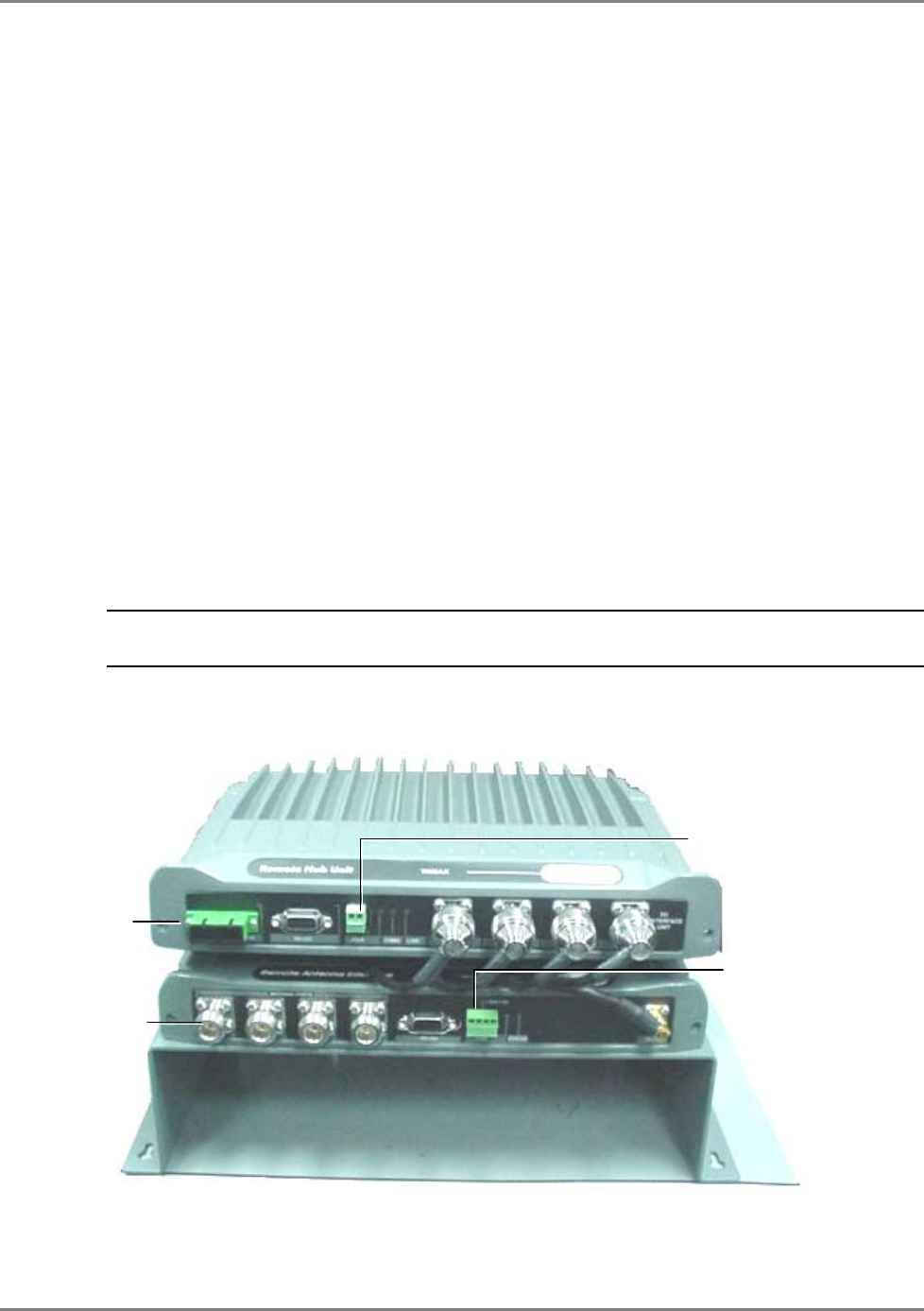
The front panel contains the antenna connections and cellular services connections, power and
local setup connections.
Figure 2-8. WiMAX RHU Front View
Four connections
to WiMAX
Remote Antenna
Units
DC PWR
–
9V
DC PWR – 15.5V
to
2-right
pins
Optic connector

WiMAX System User Manual
MobileAccess WiMAX System User’s Guide 26
Front Panel Ports
The following table describes the front panel ports.
Front Panel Ports Description
Antenna Ports 1..4 Four N-type female connections to four Remote Antenna Units
NOTE: To be terminated with 50 ohm terminations when not in use.
Optic connection Connection to optic fiber connector
Power Top unit – 9 VDC
Bottom unit – 15.5 VDC to 2 right-most pins
Front Panel LEDs
The front panel contains two LEDs, described in the following table.
Front Panel LEDs
BOTTOM Unit
Description
Run Internal operation and channel operation status.
o Green blinking – Auto-discovery completed and unit OK.
o Off – fault detected in unit (if power is supplied)
NOTE: This LED can also be used for identifying the RHU
corresponding to an MCT Configuration dialog. When the Identify
button is pressed in the MCT RHU dialog, the Run LED blinks
faster.
PWR Green – Power OK.
Off – no power supplied to the unit.
Front Panel LEDs
TOP Unit
Description
PWR Green – Power OK.
Off – no power supplied to the unit.
COM Communication status.
Blinking – normal operation
LINK Optical link status.
Steady – normal operation.
Blinking – faulty optical signal
WiMAX System User Manual
MobileAccess WiMAX System User’s Guide 27
2.2.2 Remote Antenna Unit
This is a unit installed near the antenna. It performs the final stages of filtering and amplification
of WiMAX signals. The unit supports two connections to two ports for connecting third party
WiMAX antennas and a third port for connecting to a Cellular antenna.
WiMAX System User Manual
MobileAccess WiMAX System User’s Guide 28
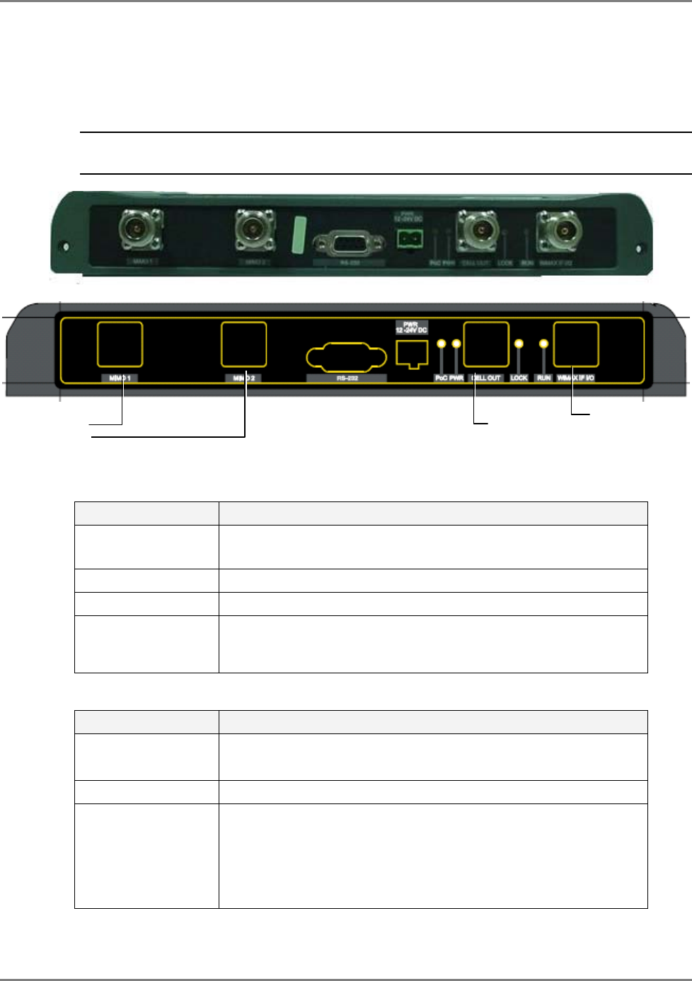
2.2.2.1 Remote Antenna Unit Front Panel
The Remote Antenna Unit front panel provides the connections to the antennas, to the WiMAX
RHU and to the DC power.
ATTENTION! DO NOT CONNECT DC TO THE REMOTE ANTENNA UNIT – IT RECEIVES
POWER FROM THE RHU.
Front Panel Ports
Front Panel Ports Description
MIMO 1/2 Connections to two WiMAX antennas
NOTE: To be terminated with 50 ohm terminations when not in use.
Cell Out Connections to Cellular antenna
WiMAX I/O Connection to WiMAX RHU
PWR ONLY FOR SERVICING THE UNIT. NOT FOR NORMAL
OPERATION.
Power connection: 15.5 VDC
Front Panel LEDs
Front Panel LEDs Description
PWR Green – Power OK.
Off – no power supplied to the unit.
Lock Synchronization error in unit.
Run Internal operation and channel operation status:
o Green constant – unit performing antenna auto-discovery. This
happens only upon power-up.
o Green blinking – Auto-discovery completed and unit OK.
o Off – fault detected in unit (if power is supplied)
T
o WiMAX MIMO
antennas To WiMAX RHU To Cellular
antennas

WiMAX System User Manual
MobileAccess WiMAX System User’s Guide 29
3 I
In
ns
st
ta
al
ll
la
at
ti
io
on
n
This chapter describes the MA WiMAX system installation procedure. The installation process will
be described according to three logical parts:
A. Telecommunications room – installing the RIUs, BUs, MA 410 controllers,
and the required
passive equipment
in the telecommunication room close to the
interface with the service providers Receivers.
B. Remote locations RHU – usually installed in the communication closet or IDF on
each floor.
C. Remote Antenna Units installed above the ceiling in close proximity to passive
antennas.
Note: Be sure to read the Pre-installation and Power Consumption related instructions before
proceeding with the actual connections.
WiMAX System User Manual
MobileAccess WiMAX System User’s Guide 30
3.1 Communication Room Installation
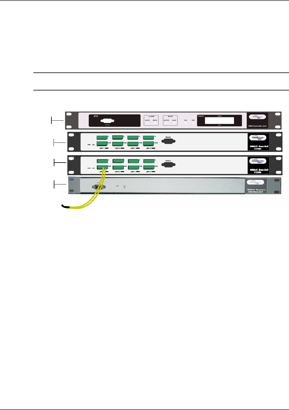
3.1.1.1 Front View
Connect the optic fibers to each port on the BU front panel.
Note: The following figure shows an 8-port Base Unit. Your installation will consists of
two 4-port
Base Units.
RIU
BU
MA 410
BU
Optic fiber connection between
BU and RHU (via patch panel)
WiMAX System User Manual
MobileAccess WiMAX System User’s Guide 31
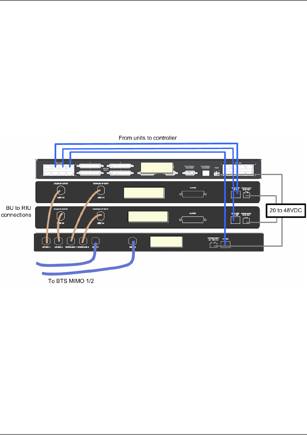
3.1.1.2 Rear View Connections
• Connect the BTS MIMO ports to the RIU MIMO ports:
• Interconnect the RIU and BU RF ports:
• Connect the RIU DL ports to the BU DL ports
• Connect the RIU UL ports to the BU UL ports
• Controller connections:
• Connect the BUs and RIU RS485 COM ports to any of the controller’s RS485 ports
• Connect the DC power to each Base Units, 410 Controller and RIU.
RIU
Wideband BU
MA 410
Controller connections
from RIU and BU
Wideband BU

WiMAX System User Manual
MobileAccess WiMAX System User’s Guide 32
3.2 Remote Site Installation
3.2.1.1 Front View Connections
• Connect the optical fibers from the Base Unit to the fiber ports on the RHU
• Connect each WiMAX RHU antenna port to the Remote Antenna Unit WiMAX I/O port of
each antenna.
• Connect the DC power to each of the RHU WiMAX Units (the Remote Antenna Unit does
NOT require power).

WiMAX System User Manual
MobileAccess WiMAX System User’s Guide 33
4 S
Se
et
tu
up
p
a
an
nd
d
C
Co
om
mm
mi
is
ss
si
io
on
ni
in
ng
g
P
Pr
ro
oc
ce
ed
du
ur
re
e
4.1 Overview
The commissioning procedure for WiMAX systems consists of four basic phases:
1. General Checks – verifying that all units are operational and that the infrastructure is in
tact allowing signals to be transferred between the units.
2. Performing Continuous Wave downlink gain adjustments
3. Performing a Continuous Wave test under each antenna.
4. Commissioning carriers onto the system
Each of the above phases will be detailed in the following sections.
4.2 Requirements
Testing Equipment/Documentation Required
• Signal Generator for generating 2695 MHz
• Optical Power meter 1310nm & 1550nm
• MobileAccess Documentation
• MobileAccess Data Sheets
4.3 General Checks
The procedures described in this section are used to verify that all units are operational and that
the infrastructure is intact allowing signals to be transferred between the units. Please read the
entire document before you attempt to commission a MobileAccess system
A summary of all the general checks is given below. Each step is detailed in the following
sections.
1. Verify connections.
2. Set up MCT monitoring - from the MCT application, logon to the MA410.
3. Verify the controller clock settings – this enables correctly time stamping any generated
events

WiMAX System User Manual
MobileAccess WiMAX System User’s Guide 34
4. Verify end-to-end link in the topology tree by ensuring that all RHUs all visible.
5. Set the base line – ensuring that disconnected units are also displayed.
6. Check each RHU DL optical level from the Base Unit and verify the band configuration for the
RHU.
7. Check Base Unit Optical Levels from the RHUs.
8. Name each BU, each RHU and each RIU.
4.3.1 Verify Connections
1. Check all RF, Fiber and Power connections before powering-up the units.
2. Apply power (first to the Bus and then to the RHUs) and verify all power and optical link
lights are on for the RIU, 410, RHUs and Base Units. Swap between the connections
between the To and From fiber ports if the link LED does not light.
3. Remove the fiber connected to each “From” port on the Base Unit(s) and use an Optical
Meter to measure the signal.
Expected level: >0dBm @ 1310nm.
Corrective action: If the signal is not at the expected level, clean all connectors, if problem
persists carry out a full sweep of the fiber connection using an Optical Time Domain
Reflectometer (OTDR)
WiMAX System User Manual
MobileAccess WiMAX System User’s Guide 35
4.3.2 Set Up MCT Monitoring
To set up monitoring via MCT
1. Install the MCT application (from the CD provided with your kit) on the computer from which
you will be performing the commissioning procedure.
2. Connect to the RS232 port on the front of the MA Controller 410(as illustrated below).
3. Launch the MCT and Log in using Field Eng user and eng password.
Note: You may have to use a USB cable with a serial connection if your computer lacks a DB9
serial port.
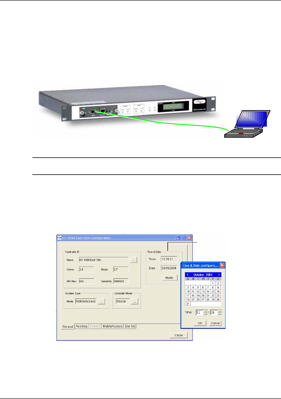
4.3.3 Verify the Controller Clock Settings
Verify the Controller date and time settings are correct as follows:
• In the Network Topology, double-click on the controller.
• In the invoked dialog, choose the General tab.
• In the Time and Date area, verify the correct time (24 hour clock) and date are
defined. The date is represented as DD/MM/YYYY.
• To modify, click on Modify and make the required changes in the invoked dialog.
Date and Time
RS232
WiMAX System User Manual
MobileAccess WiMAX System User’s Guide 36
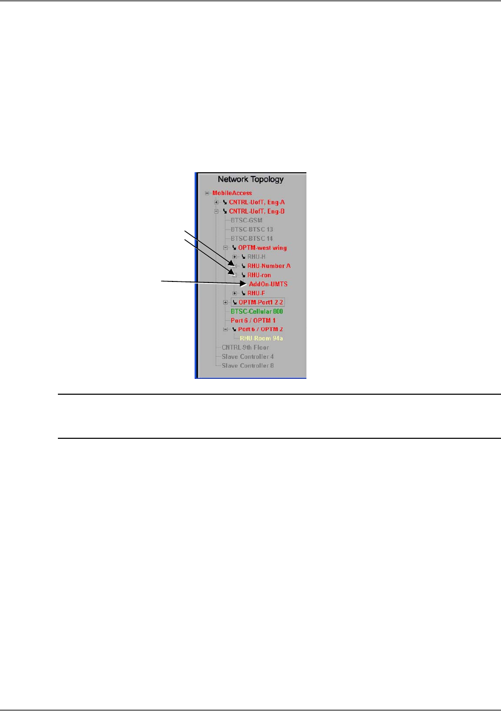
4.3.4 Verify End-to-End Link in Topology Tree
Verify end-to-end link connection by ensuring that each RHU is displayed in the Network
Topology tree.
To view the RHUs in the Topology Tree
The RHUs are listed under the corresponding Base Unit, referred to as OPTM in the tree. (An
OPTM is a four port module of a BU – i.e. an 8-port BU is listed as two OPTMs). Each RHU is
listed according to the BU (OPTM) port to which it is connected. Each Add-on is listed under its
host RHU.
IMPORTANT NOTE! If the RHUs are not all visible, reset or power cycle the Base Units to
which it is connected. If this does not resolve the problem, troubleshoot the optical links for dirt
or other problems.
WiMAX System User Manual
MobileAccess WiMAX System User’s Guide 37
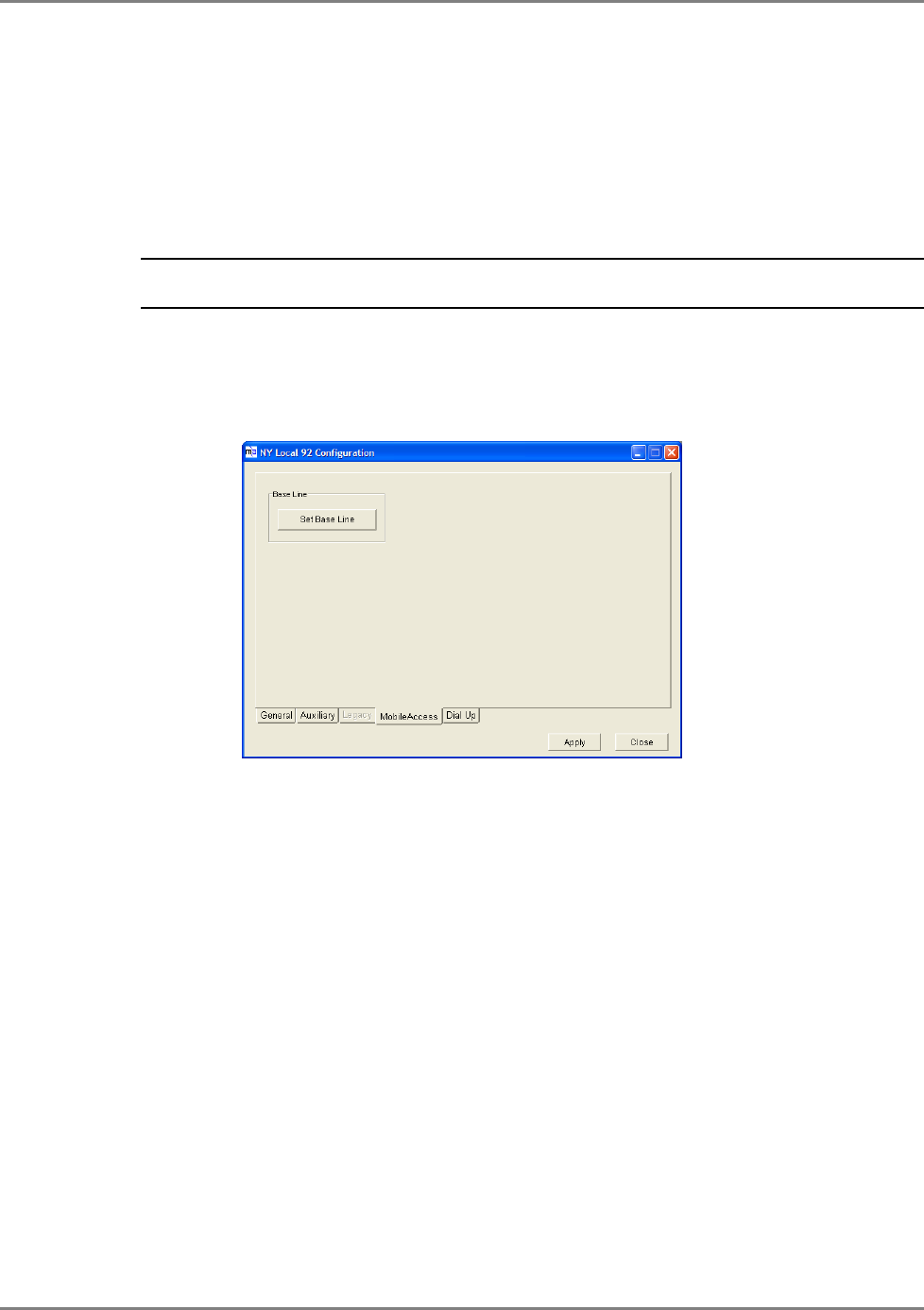
4.3.5 Set the Base Line
Once all equipment on site is visible in MCT, set the base line. This sets
all
the MobileAccess
devices currently displayed in the Network Topology pane as a reference and will continue
displaying them (in red versus gray) if communication is lost.
Note: Mobile Access devices that are not displayed in the tree when the Base Line button is clicked will
disappear if communication with them is lost.
To set the baseline for each controller
1. Double-click on the Master Controller in the Network Topology tree and in the invoked
dialog, click the MobileAccess tab.
2. In the MobileAccess tab, click the Set Base Line button.
4.3.6 Verify End Units Optical Signal and Service Band
To Verify End Units Optical Signal and Service Band
1. Select each RHU and in the invoked dialog, click the General tab.
2. Verify the downlink optical signal level on each RHU by reading the signal value under
Optical Link Level.
Greater
than 100 is very good. If it is less than 80, determine why (dirty fiber, too many
splices/patch panels). The system can compensate for optical levels down to about 70. If it
is that low, clean the fiber using CLETOP cleaners as appropriate for male connectors and
female receptors.
WiMAX System User Manual
MobileAccess WiMAX System User’s Guide 38
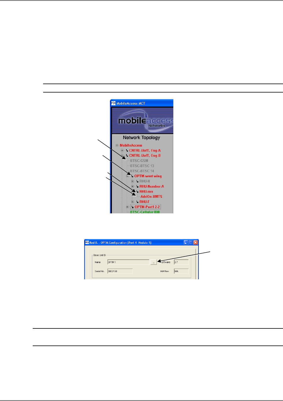
4.3.7 Name the BUs, RHUs and RIUs
Name all the RHUs, Base Units (OPTMs) and RIU using an appropriate naming convention –
which indicates the services they support, their location and/or their host cabinet (when
relevant).
To name the units
1. In the Topology Tree, double-click on the relevant unit.
Note: BUs are listed as OPTMs, RIUs are listed according to RIU WiMAX.
The corresponding dialog is invoked with the General tab displayed by default. A partial
OPTM dialog is illustrated below; however, the Name field is the same for all the units.
2. Click the Name Browse (…) button and enter the unit name.
4.4 Adjustment Procedure
ATTENTION! It is required to perform the optical adjustment procedure during
installation. The procedure takes about 3 minutes.
The WiMAX system requires two types of adjustments:
• Downlink adjustments to calibrate the gain of the system to account for different fiber
lengths and their resultant losses. (from RIU to RHU FO input)
• Cable adjustment for each channel (RHU antenna port to remote antenna unit).
RIU module
BU module
RHU
Add-on
Name Browse
button
WiMAX System User Manual
MobileAccess WiMAX System User’s Guide 39
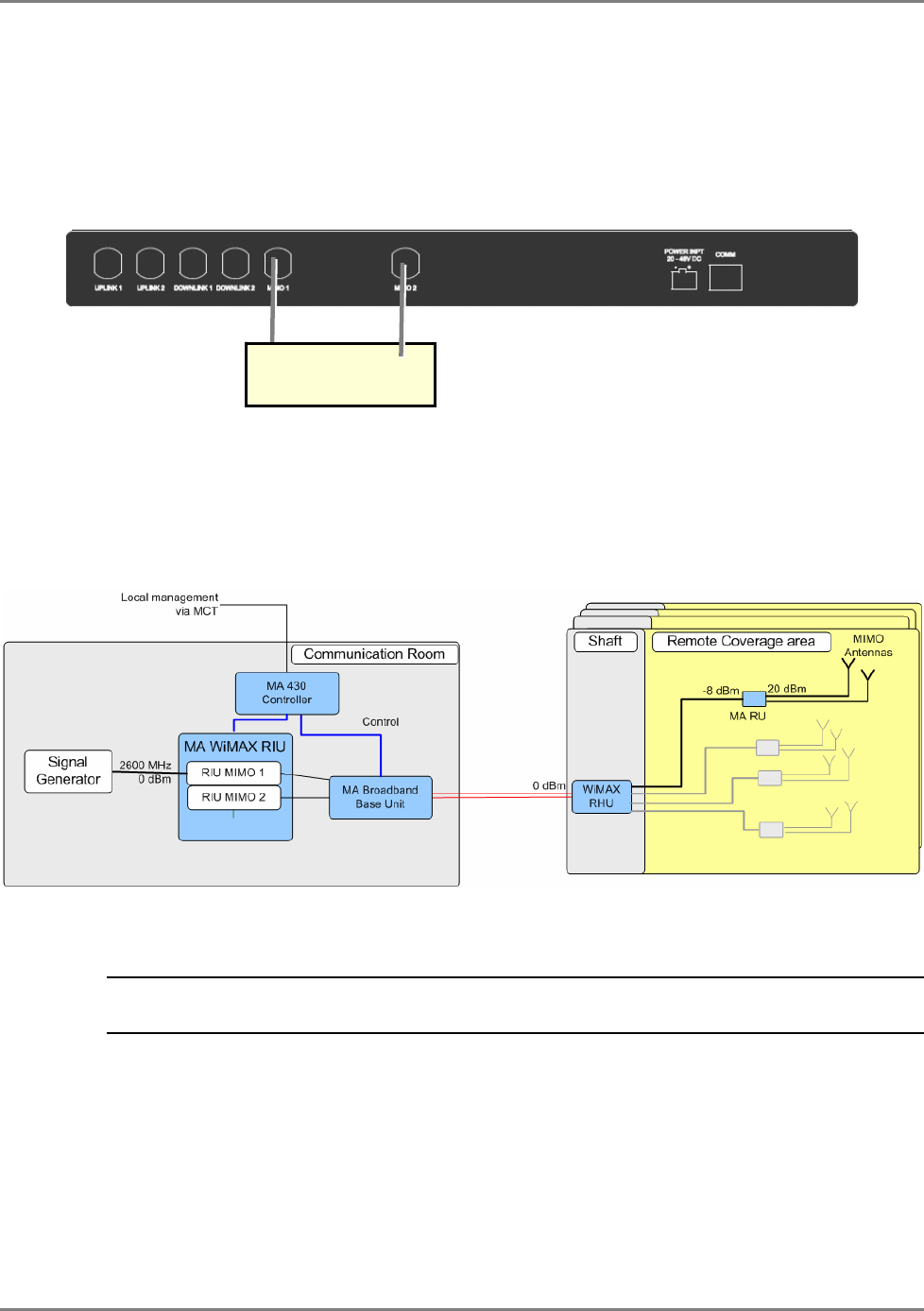
Both procedures are performed via the RHU Adjustment tab.
To perform adjustment procedure
• Connect signal generator at a frequency of 2695 MHz at 0dBM to the RIU MIMO1 and
MIMO2 ports
• Verify the target power at the RHU input port and at the Antenna Interface Unit is as
illustrated below (0dBm at RHU input, -8 dBm at the RU Input and 20dBm at RU output) by
doing the following:
The adjustment procedure can be performed simultaneously for all RHUs and Remote Antennas
in the system from the configuration dialog of
any of the RIUs
in your WiMAX system.
Note: Each RIU contains a list of all other RIUs and all other RHUs and Remote Antenna Units so
the adjustment is performed on all these units at once.
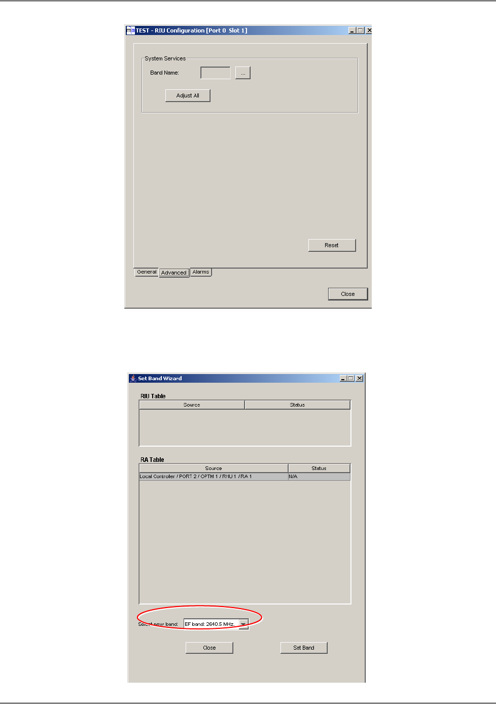
To perform the adjustment procedure
1. In the Topology Tree, double-click on any of the RIU modules. The RIU configuration
dialog appears. Click the Advanced tab. The following pane containing the adjustment
options appears.
Signal generator
2695 MHz, 0 dBm
WiMAX System User Manual
MobileAccess WiMAX System User’s Guide 40
2. In the Band Name, select the sub-band in which the system will operate by doing the
following:
• Clicking the adjacent Browse (….) button. The following pane appears.
WiMAX System User Manual
MobileAccess WiMAX System User’s Guide 41
• In the Select New Band field, choose from the following bands (the list below shows
the center frequency of each band) and click Set Band:
o AB: 2502-2535 MHz (2518.5 ±15MHz)
o CD: 2535-2568 MHz (2551.5 ±15MHz)
o EF: 2624-2657 MHz (2640.5 ±15MHz)
o GH: 2657-2690 MHz (2673.5 ±15MHz)
You will return to the Advanced pane.
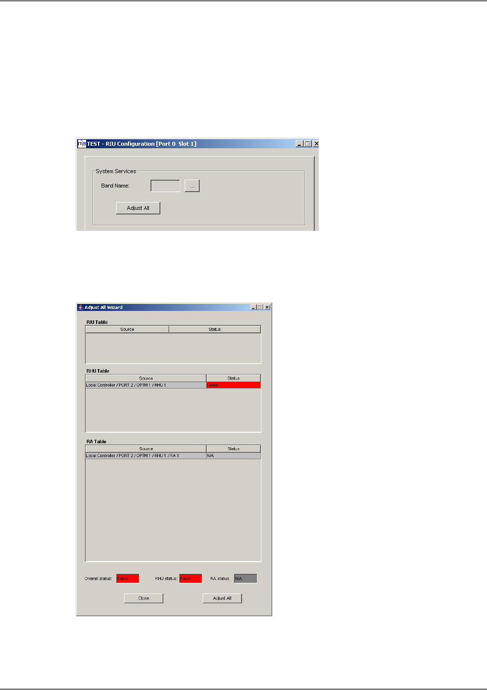
3. In the Advanced Pane, click Adjust All. The adjustment pane appears.
The pane shows (as groups) the RIUs, RHUs and RAs in the system. The overall status of
the elements is displayed t the bottom of the pane, where the highest alarm level of any
group of elements is displayed. (i.e. if one of the RHUs is RED then, the RHU status is RED).
4. Click Adjust All to initiate the adjustment procedure. A verification dialog appears.
Respond with Yes to begin the procedure.

WiMAX System User Manual
MobileAccess WiMAX System User’s Guide 42
5. Click Adjust All. The adjustment dialog appears.
5 U
Us
si
in
ng
g
M
MC
CT
T
5.1 General
Once the system devices have been mounted and connected for each controller, install the MCT
on a (laptop) computer and use the MCT application (provided with your NMS system) to verify
the installation and configure the parameters of the devices relevant to the connected controller.
MCT Features and capabilities
• Hierarchically display of the connected controller and the hosted devices with status
information
• Automatic detection of MobileAccess Base Units, RIUs, RHUs and Add-on devices
• Base Line setting for MobileAccess site devices that shows which devices should be
connected even if communication is lost with a specific device
• Three access levels: Operator, Engineer and Technical Support
• Stand-by option enables receiving event notification for dial-up connection if the status
of the connected controller changes
• Inventory of equipment (BUs, RHUs) connected to the controller can be exported as a
CSV file to be viewed via an external application (i.e. Excel)
• Intuitive adjustment procedure using either a real or emulated signal for MobileAccess
devices ( Chapter 4.)
• Backward compatibility with MCT and device S/W versions 3.0 and higher
WiMAX System User Manual
MobileAccess WiMAX System User’s Guide 43
5.2 Getting Started
The configuration procedure is performed through a PC that is serially connected to the Master
(or standalone) controller.
Install MCT on a PC (or laptop) meeting the requirements specified in the datasheet and create a
shortcut to the application on your desktop.
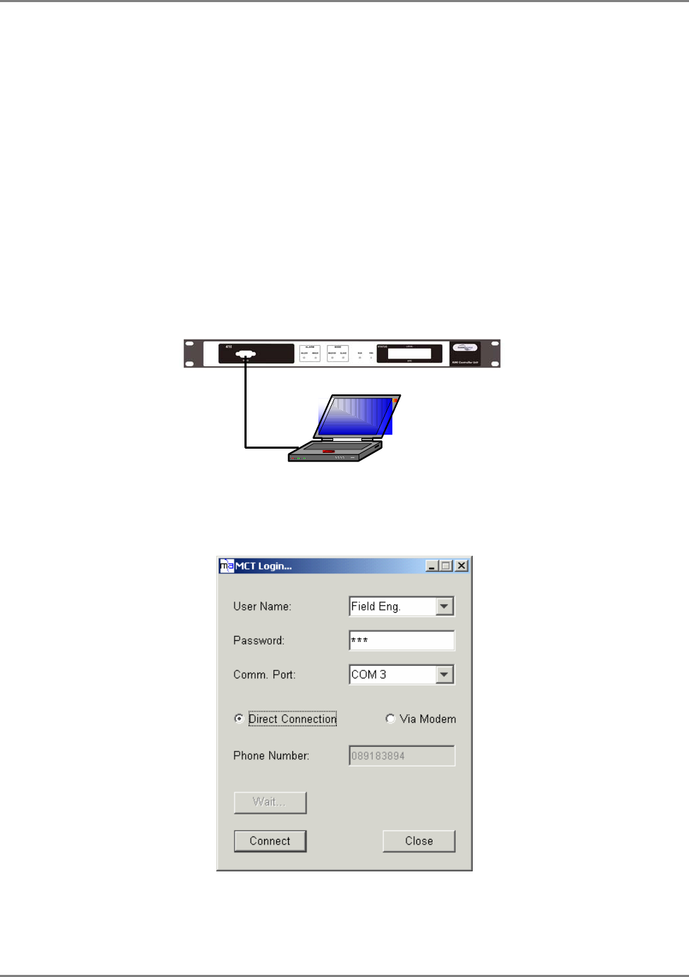
5.2.1 Serial Connection and Login
To connect to the controller locally
1. Connect the computer on which the MCT application is installed to the RS232 card
connector, as illustrated below.
2. Launch the MCT application by double-clicking on the MCT icon on the desktop. The Login
dialog appears.
3. To access the MCT screen at a level that provides access to configuration options, select the
User Name ‘Field Eng’ and enter the default Engineering password ‘eng’.
Laptop with MCT
application
WiMAX System User Manual
MobileAccess WiMAX System User’s Guide 44
Note: The User Names determine the access levels. For more information on the User Names,
Passwords and Password change, refer to section
0.
4. Select the Comm Port according to the communication port to which your computer is
connected.
5. Click Connect. The MCT main window appears.
5.2.2 Dial-up Modem Connection and Login
You may remotely connect to the MA 410 controller via dial-up connection. For this connection
to be available, the controller must be connected to a phone line.
Note: Once the initial configuration procedure has been completed, the controller can be set to
notify of events through the dial-up connection (refer to section Error! Reference source not
found.).
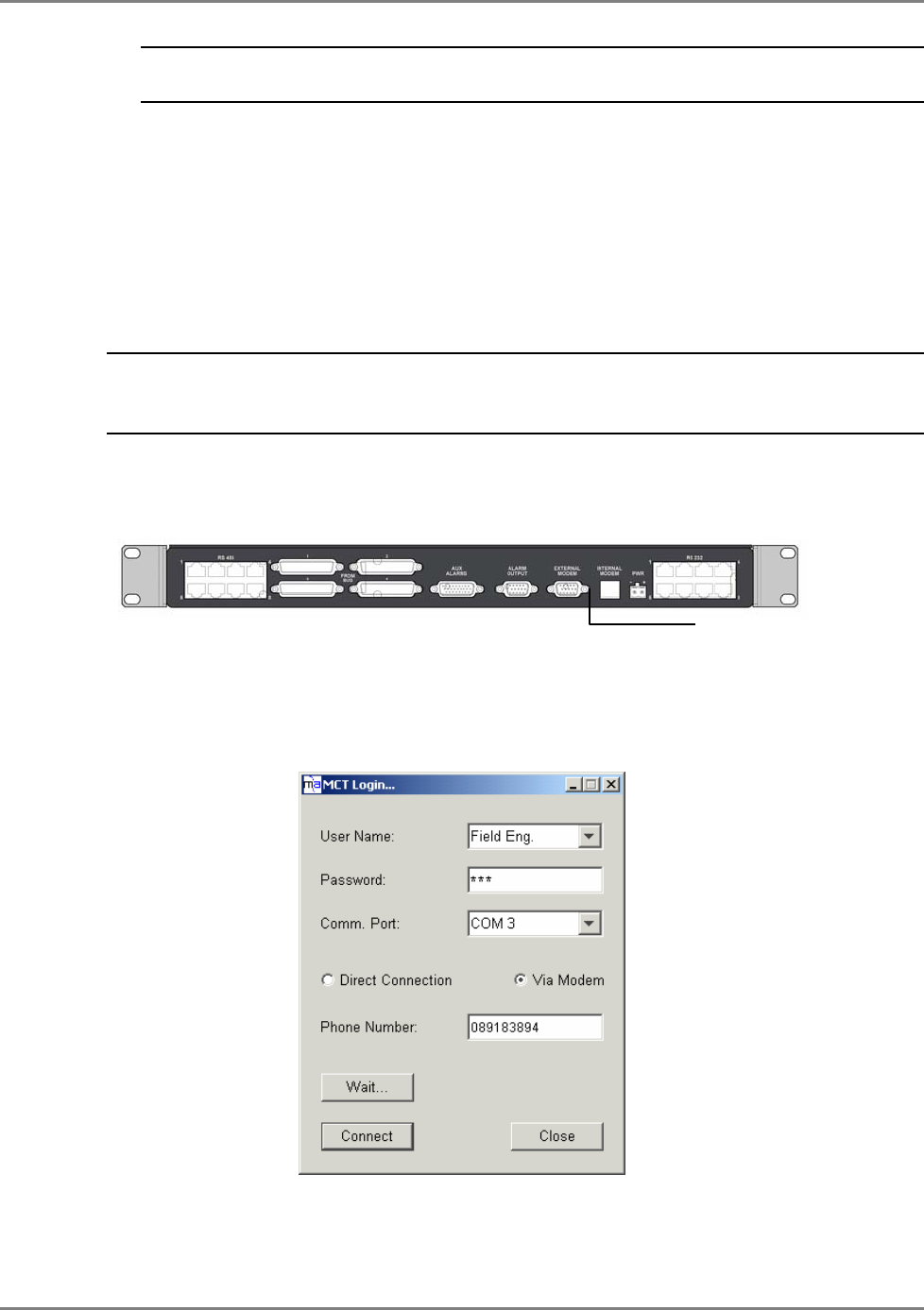
To connect to a MA 410 controller from a remote dial-up connection
Connect the controller External Modem port to a phone line.
1. At the remote location, connect your computer dial-up modem connection to a phone line
and note your dial-up port number.
2. Launch the MCT application on your computer. The MCT Login dialog appears.
3. To access the MCT screen at a level that provides access to configuration options, select the
User Name ‘Engineering’ and enter the default Engineering password ‘eng’
Phone line connection

WiMAX System User Manual
MobileAccess WiMAX System User’s Guide 45
Note: The password can later be changed from the Security menu (in the main window). The access
levels and passwords are described in
0..
4. In the MCT Login dialog, select Via Modem… select the Comm Port on the computer and
enter the Phone Number of the line connected to the controller.
Enter the phone number in the following format:
A phone number that is up to 12 digits, where a coma (,) indicates a ‘wait’ state required
when an outside line is accessed. For example: 9,4234889805 where ‘9’ accesses an
outside line, ‘423’ is the area code, and ‘4889805’ is the number.
5. Click Connect. You will be connected within a few seconds.
6. You may now perform the configuration procedure.
WiMAX System User Manual
MobileAccess WiMAX System User’s Guide 46
5.3 Navigating the MCT Application
The MCT main window shows all the currently connected and defined devices and their status
and provides access to device management functions as well as to system management options
such as security, file export, etc.
The MCT window is divided into the following areas:
• Menu Bar - provides access security, events display and report generation options
(section 5.3.1).
• Network Topology – hierarchically displays the defined and available site devices and
their status. (see 5.3.2)
• Work Area – the display corresponds to the selected menu or tree item (section 5.3.3)
Note: For optimal response time, it is recommended to open the minimum required windows and
close windows that are no longer necessary. A window that is not edited for five minutes will be
automatically closed. A window acceleration mechanism accelerates the responses when
adjustments are made by temporarily refreshing only the active window (events, Topology View,
Device View, etc. will not be updated).
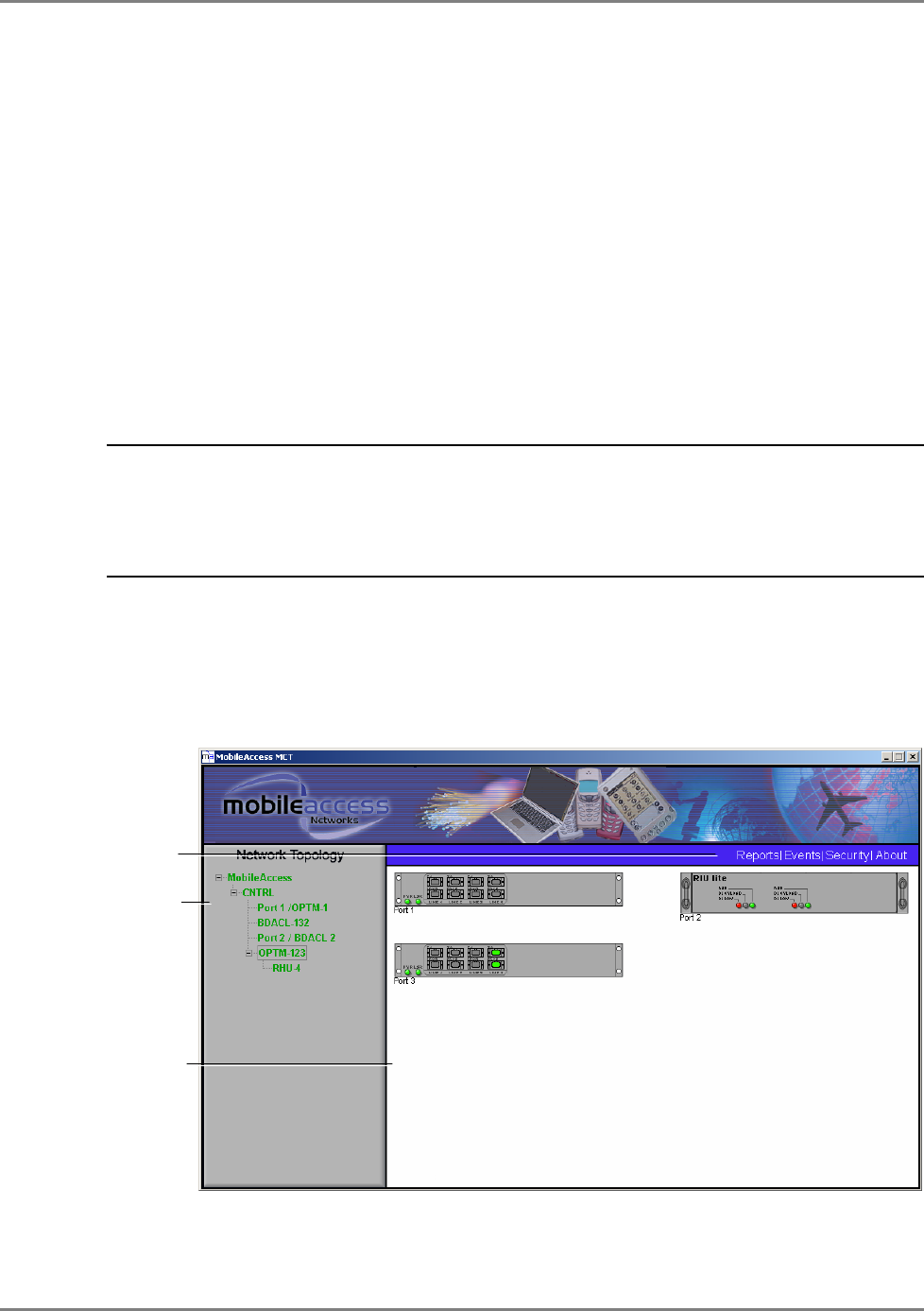
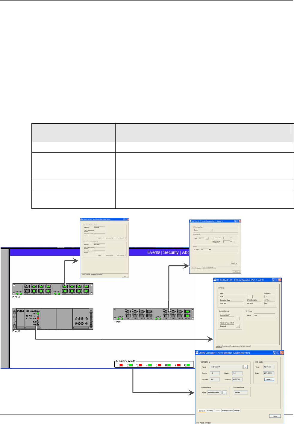
The figure below shows the Work Area display when the CNTRL item is selected. It shows any
Base Units and RIUs connected to the controller. Control dialogs for the device or for elements
hosted by these devices (RHUS for BUs or BTSC/BDAC for RIUs) are accessed from the tree or
by double-clicking on specific areas of the device.
Figure 5-1. MCT Main window
Network Topology
tree
Work Area
Menu Bar
WiMAX System User Manual
MobileAccess WiMAX System User’s Guide 47
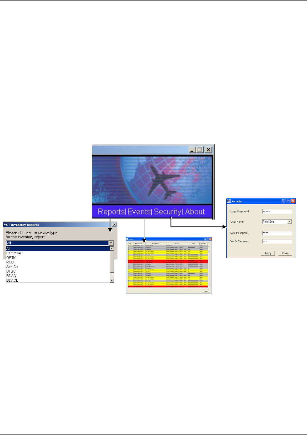
5.3.1 Menu Bar
The Menu Bar contains the following options:
• Reports – used to generate a tabular summary of information on connected devices
(section 5.9).
• Events – click to show the events that occurred on the monitored devices.
Configuration changes that are initiated by the network manager are not considered
events display. (section Error! Reference source not found..
• Security – Accessible only to Engineer user level. Provides password change option
(section).
• About – click to view the MCT version. Useful for upgrades.
WiMAX System User Manual
MobileAccess WiMAX System User’s Guide 48
5.3.2 Understanding the Network Topology Tree
Note: It is important to understand the Network Topology display since you will be required to
verify the device connections before the configuration procedure can be performed. The MCT
Network Topology tree display differs from the NMS Network Topology Tree display.
The MCT Network Topology tree shows a
single
connected controller to which the session was
opened, and the hosted devices – RIUs, Base Units, RHU. The view displays both connected and
disconnected network devices in the appropriate hierarchy and colors corresponding to their
status.
The MCT Network Topology tree includes problem sourcing features such as:
• Color indication corresponding to the elements status
• Real-time updates of device status
• Upward propagated element status colors
• Arrows indicators leading towards the element that is the source of the problem
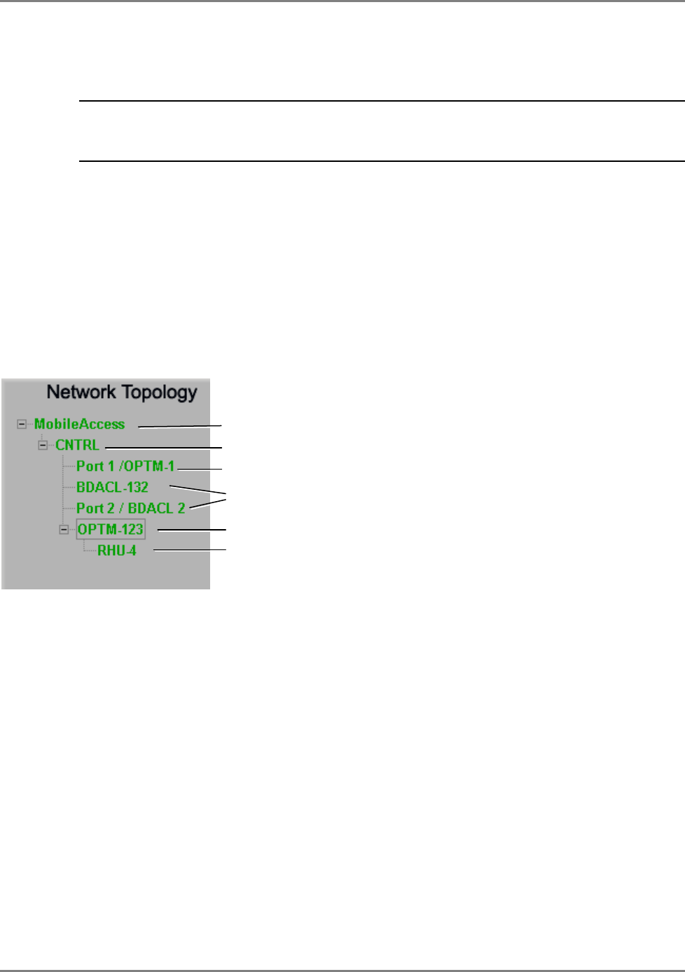
The devices are displayed as follows:
• CNTRL – controller
• BDAC/WRIU – RIU displayed according to BDAC or WRIU modules, where the suffix ‘L’
(i.e. BDACL) stands for RIU Lite.
• OPTM-1/OPTM-2 - Base Unit displayed according to 4-port modules, where each 4-port
module is referred to as OPTM. Each OPTM is displayed along with the Controller port to
which it is connected.
• RHU – Remote Hub Units. Each RHU is displayed under the OPTM to which it is physically
connected, along with the OPTM port to which it is connected.
Root item
Controller
Base Unit module
RIU - BDAC
Base Unit module
RHU

WiMAX System User Manual
MobileAccess WiMAX System User’s Guide 49
5.3.2.1 When and how are devices displayed in the tree?
• Connected devices are displayed in green, red or yellow. Disconnected, or future
devices that have been defined to the base-line, are displayed in gray.
• MobileAccess devices – RIUs, MA BUs and MA RHUs and Add-ons.
• Connected MA devices are automatically identified. It is recommended to assign a name
to each device.
• Disconnected MA devices are displayed in gray (once a base-line has been set as part of
the configuration procedure
• Newly added RHUs or Add-on devices are identified only after the host OPTM has been
reset (either locally or through the configuration dialog).
• Legacy devices – Legacy BUs and RHUs.
• Legacy BUs and RHUs are detected only after they have been configured.
5.3.2.2 Tree Status Colors
Faults are propagated only through an arrow so that the faulty device can be quickly identified
by its color. The tree colors indicate the status of the elements:
Color Indicates
Green OK
Yellow Minor error.
Red Major error.
Gray No communication to a (MobileAccess) device set in Base-
Line. If communication to a device that was not set in
Base-Line is lost, the device disappears from the display.
Blue Version incompatibility (device version 3.0 and host
controller version 3.1)
WiMAX System User Manual
MobileAccess WiMAX System User’s Guide 50
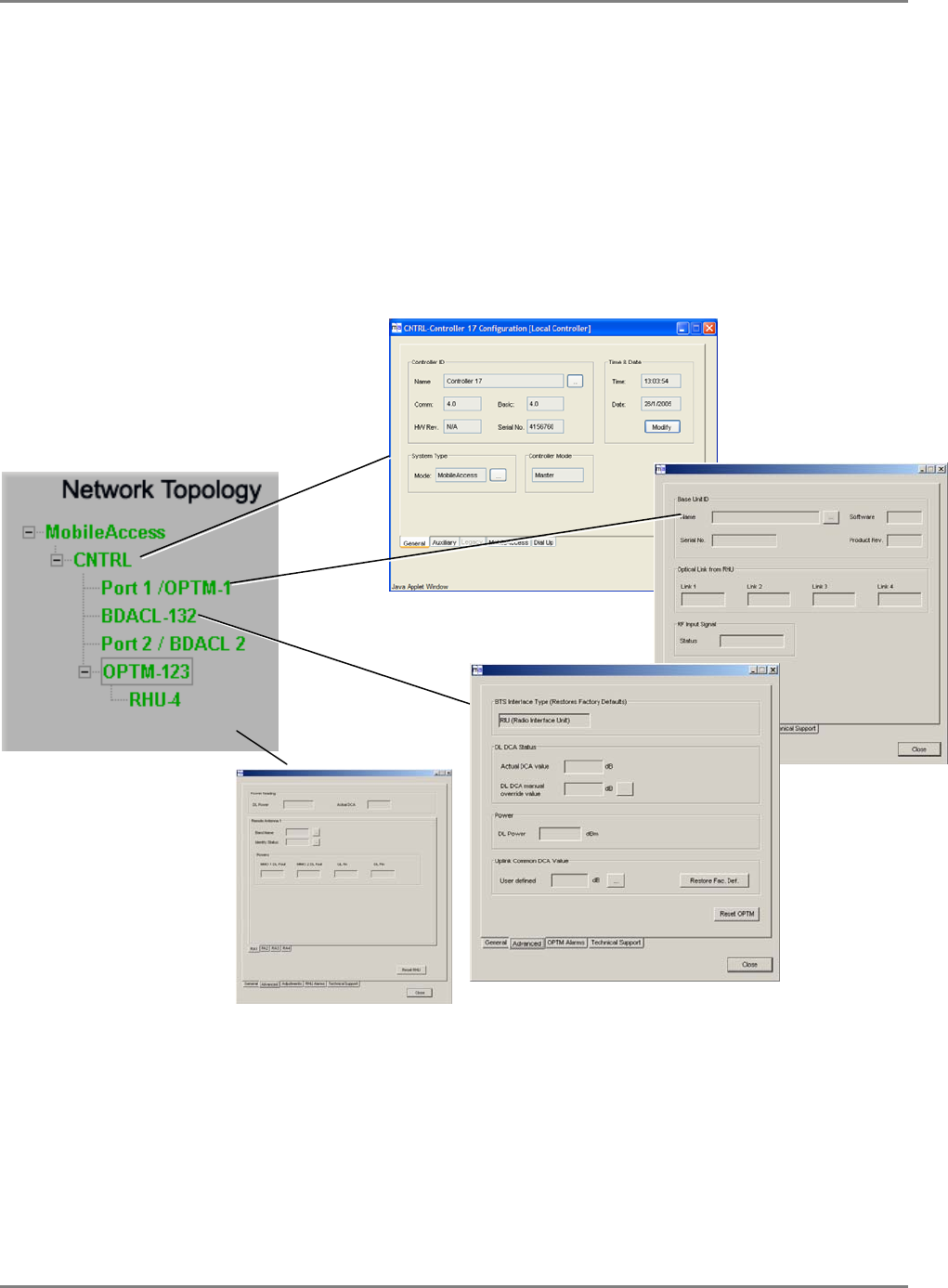
5.3.2.3 Invoking configuration dialogs from the Topology tree
All device configuration dialogs may be invoked from the topology tree by clicking on the
appropriate items. This includes the configuration dialogs for the MA 410/430 controller, BTSC,
OPTM, RHU and add-on unit.
Note the following:
• Each OPTM (Base Unit module) is managed by a dedicated dialog
• Each BTSC/BDAC (RIU module) is managed by a dedicated dialog
WiMAX System User Manual
MobileAccess WiMAX System User’s Guide 51
5.3.3 Device View Pane
The Device View pane provides a display of the status of the BU, RIUs and Auxiliary Ports
connected to the
selected
controller. The configuration dialog for each OPTM, BTSC, RHU and
Add-on can be invoked by clicking on the appropriate icon.
Note the following:
• Each OPTM (Base Unit module) is managed by a dedicated dialog.
• Each BTSC/BDAC (RIU module) is managed by a dedicated dialog
To invoke configuration dialog from the Device View
To invoke the
configuration dialog for: Do this:
A WRIU unit Click on the relevant WRIU in the RIU image
An OPTM unit Click on an
empty space
in the relevant OPTM in the BU image.
Do not click on the LEDs in the OPTM –
this will invoke the RHU
configuration dialog.
An RHU unit Click on the appropriate LED in the relevant OPTM view.
The Controller Click on the Auxiliary Alarms icon. The icon appears only after
auxiliary connections have been enabled for that controller.
Figure 5-2. MCT Display View pane
RHU dialog –
click the LED OPTM dialog – click
the OPTM space
BTSC dialog
Controller dialog
Controller dialog
WiMAX System User Manual
MobileAccess WiMAX System User’s Guide 52
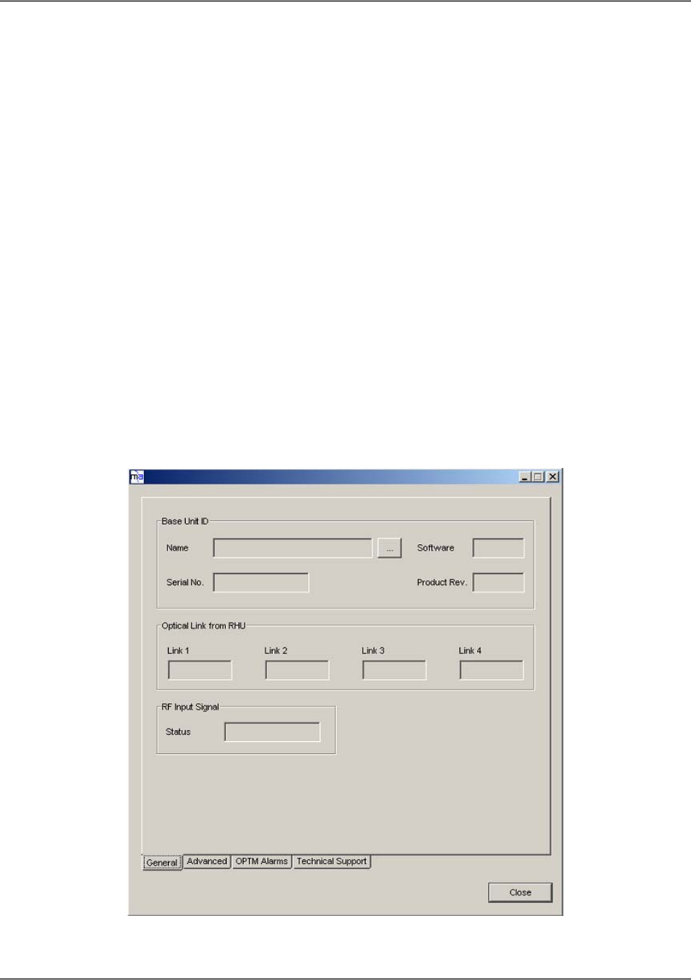
5.3.4 About Device Configuration Dialogs
Each MA device has an individual configuration dialog that provides configuration, control and
monitoring options.
• RIU, OPTM and RHU device configuration dialogs may be invoked either by:
• Double-clicking on the device in the Network Topology tree
• Double-clicking on the appropriate image area in the Device View
In general, the device configuration dialogs contain four panes:
• General – provides device version and identification definitions
• Advanced – device control parameters such as signal control, disable, and device reset
• Adjustment – used for the adjustment procedure
• Alarms – device specific alarms used for fault sourcing
The parameters vary depending on the device type. Below is and example of the OPTM
configuration dialog showing the General tab. The configuration dialogs are described in section
5.6 - Controller Configuration, and section 5.7 - Configuring MobileAccess Devices
WiMAX System User Manual
MobileAccess WiMAX System User’s Guide 53
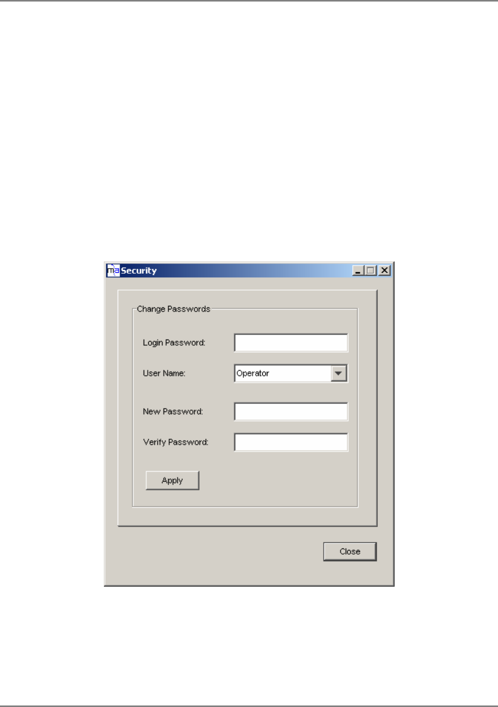
5.4 Authorization Levels and Passwords
MCT enables access at three authorization levels. Each level is provided with a default password
that can be changed through the Security menu.
Authorization Levels
• Oper – enables the user to view the configuration and the events display. Events
acknowledge capabilities are not available to Operator level users. Default password =
‘oper’
• Field Eng – provides configuration capabilities to all options displayed at this entry
level. Default password = ‘eng’
• Technical Support – restricted to MA service personnel.
To modify the password
1. Click on the Security menu. The following dialog appears.
2. Select the User Name whose password is to be modified.
3. In the Login Password, enter the current password.
4. In New Password type the new password. Type the password again in Verify Password.
5. Click Apply.

WiMAX System User Manual
MobileAccess WiMAX System User’s Guide 54
5.5 Configuration Overview
1. Name and configure the controller system parameters ( 5.6.1) and auxiliary parameters if
relevant ( 5.6.2).
2. Configure each of the devices it host: RIUs, BUs, RHUs. Refer to the instructions given in
the following sections.
3. Once the basic configuration is completed, perform the adjustment procedure according to
MA1000/2000 Commissioning Guide
. Once the adjustment procedure is complete, all devices
should be displayed in green.
4. You may then monitor the site through the MCT topology tree and source any detected
faults (red or yellow colored devices) through the device view configuration dialogs.
5. Review the configuration via Inventory Reports (section 5.9).
5.6 Controller Configuration
A number of simple configuration steps must be performed:
This section describes the steps required to:
• Configure the controller system parameters – name and time and date
• Configure auxiliary devices connected to the controller (if relevant)
• Configure support for MobileAccess WiMAX devices.
Note: All configuration procedures are performed through the controller dialog – invoked by
double-clicking on the controller item in the Network Topology.
WiMAX System User Manual
MobileAccess WiMAX System User’s Guide 55
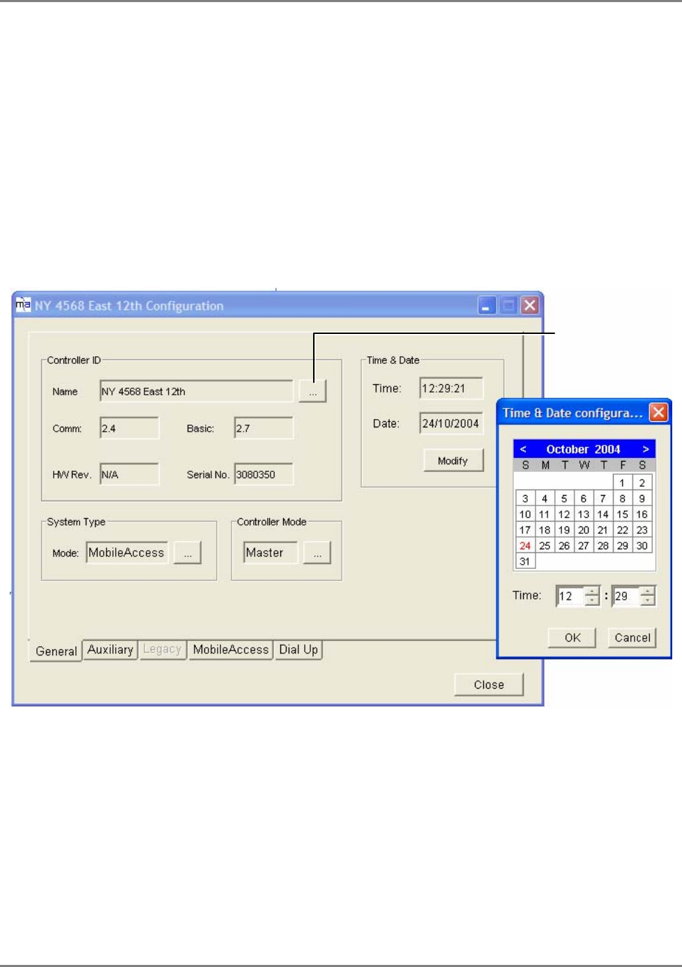
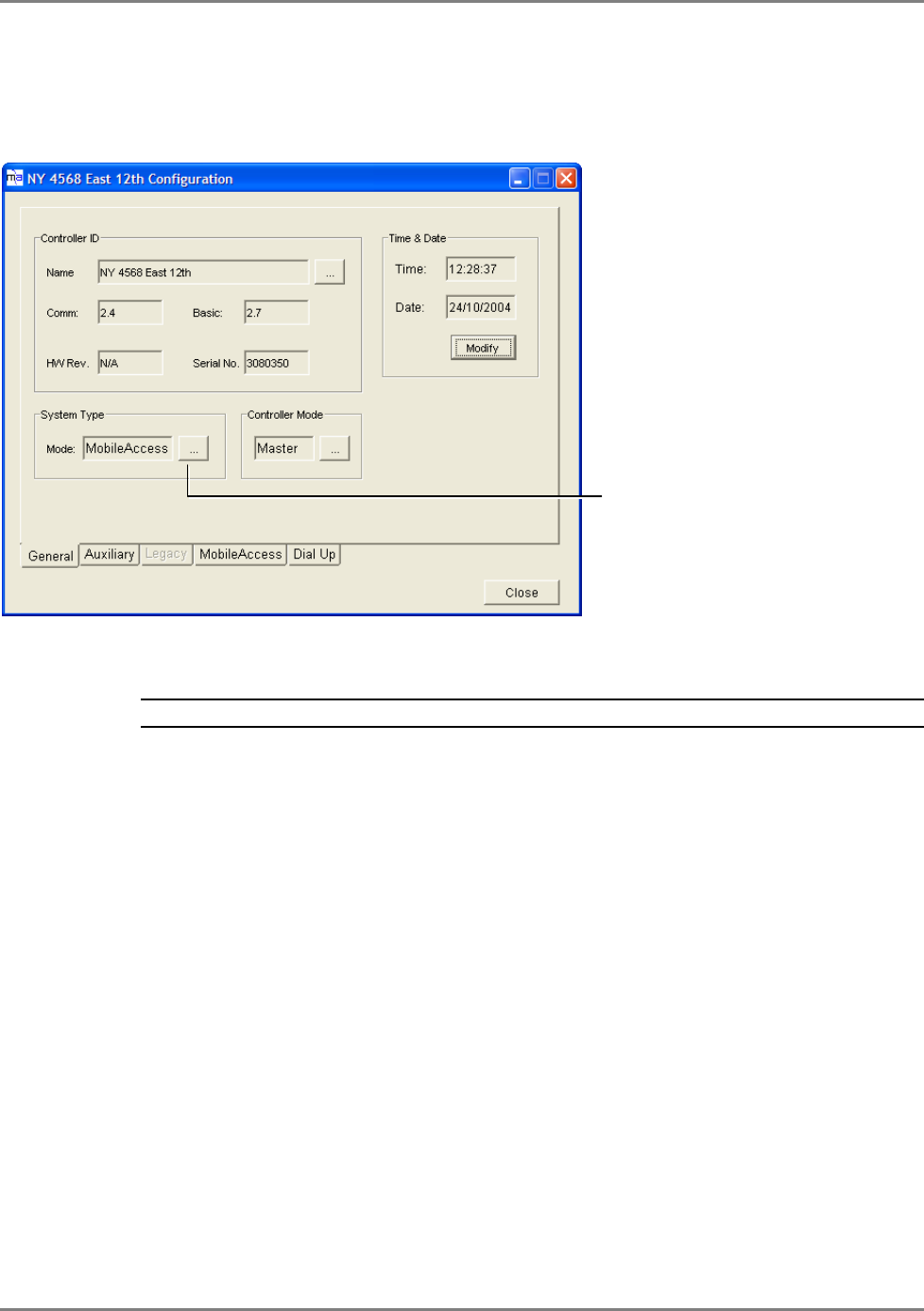
5.6.1 Configuring Controller System Parameters
It is recommended to assign the controller a recognizable name that would indicate its location,
and to verify that the correct time and date are set for the controller since events for devices
under this controller will be received with the set time and date.
To configure the controller system parameters
1. In the Network Topology, double-click on the controller to be redefined. The controller
configuration dialog appears.
2. Choose the General tab.
Figure 5-3. Controller Configuration Dialog
3. Click the Name browse button and type the controller name - up to 20 characters including
spaces.
4. In the Time and Date area, verify the correct time (24 hour clock) and date are defined; to
modify, click on Modify and make the required changes in the invoked dialog:
• In the calendar, choose the date, using the <arrows> to scroll to the correct month if
necessary
• In the Time field, set the hour and minutes
• Click OK.
Click to set the
controller name
WiMAX System User Manual
MobileAccess WiMAX System User’s Guide 56
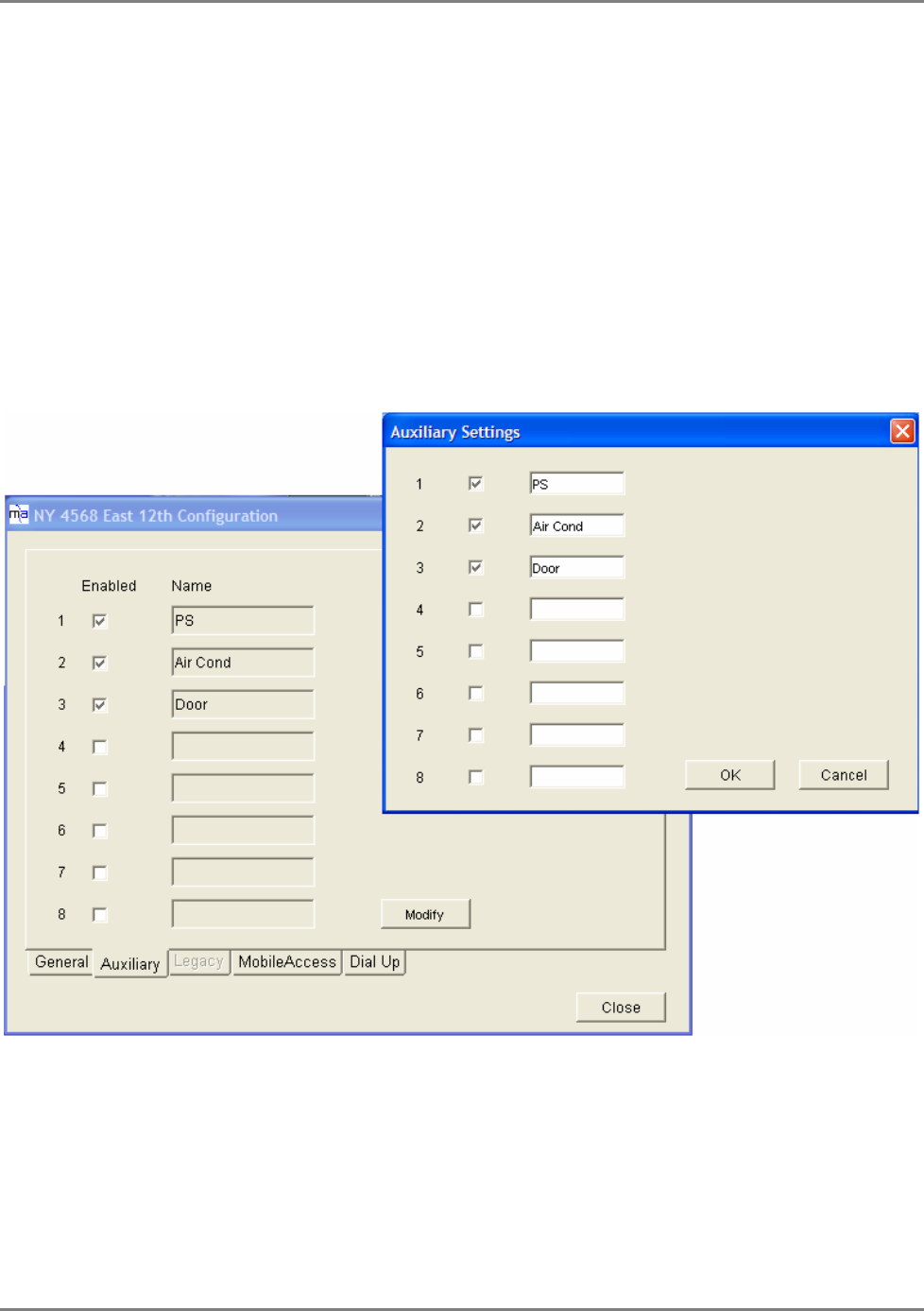
5.6.2 Configuring Auxiliary Devices
Auxiliary devices such as switches for power supplies, air conditioners or door-open indicators,
that are connected to the controller can be monitored through LEDs displayed in the MCT.
The auxiliary device LEDs are displayed in the Device View pane, when the corresponding
controller is selected –
but only after the auxiliary device connections have been configured.
To configure connected auxiliary devices
1. In the configuration tree, double-click on the MA 410 controller to be configured to invoke
the controller configuration dialog and select the Auxiliary tab.
The enabled (relevant) connections are colored blue (i.e. 1,2 and 3 in the example below).
The (user defined) name assigned to each connection is displayed alongside the connection
(i.e. PS, Air Cond and Door).
Figure 5-4. Auxiliary Device dialog
2. To change the active connections and assigned names, click Modify. The Auxiliary Settings
dialog appears.
3. Checkmark each of the Auxiliary pins to be activated, assign them identifiable names and
click OK.
WiMAX System User Manual
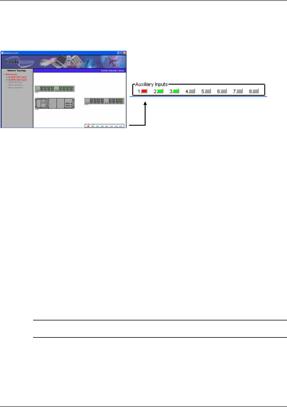
MobileAccess WiMAX System User’s Guide 57
• In the Auxiliary tab, the enabled Auxiliary connections will be marked by blue LEDs.
• In the Device View pane (along with the other devices connected to the controller),
the enabled auxiliary connections will be displayed in either green or red (depending on
their status) when the host controller item is selected in the Network Topology.
Figure 5-5. Auxiliary Device View
5.7 Configuring MobileAccess Devices
Once the controller has been configured to operate with MobileAccess devices, these type of
devices are automatically identified by the controller and are displayed in the Network Topology.
Additional device parameters may then be configured according to the installation and site
requirements. For example, if your system includes an RIU, each BU must be configured to
receive its RF signal source via an RIU (since by default it is configured to interface with passive
interface).
The procedures are performed from the configuration dialog of each device. The dialog is
invoked by double-clicking on the element in the Network Topology or in the Device View
pane.
5.7.1 Configuring for a MobileAccess Device Hosting
In this mode, the controller activates an Auto detection mechanism that constantly monitors its
RS485 rear panel ports for BUs and RIU devices.
RHUs and add-ons are detected in a similar manner by their host OPTM (BU element)
every time
the BU is powered-up or reset from the MCT
and added to the Network Topology.
Note: Newly added RHUs or add-on’s will be detected by the OPTM only after the OPTM has
been reset. The reset can be software executed through the OPTM configuration dialog.
Zoom-in of auxiliary ports display. Defined ports are
displayed in Green (OK) or Red (fault detected).
Undefined ports are displayed in grey (not relevant).
WiMAX System User Manual
MobileAccess WiMAX System User’s Guide 58
To configure a controller with MobileAccess devices
1. In the configuration tree, double-click on the MA 430 controller to be configured to invoke
the controller configuration dialog and select the General tab.
2. Under System Type, verify that MobileAccess is selected, clicking the Mode Browse
button and selecting the option if necessary. The MobileAccess tab should become available.
Note: Close and reopen the dialog if the tab does not become available within a few seconds.
3. Verify that all the MobileAccess devices (RIUs, OPTMs, RHUs and Add-ons) connected to this
controller are displayed in the Network Topology pane under their corresponding hosts, and
are colored green, red or yellow. Any of these colors are acceptable before the adjustment
procedure has been performed.
5.7.2 Adding a New MobileAccess Device
Each time a MobileAccess device is added to the system, the Base Line must be set again.
To reset the Base Line
1. In the Topology Tree, double-click on the controller hosting the new device.
2. In the controller configuration dialog, select the MobileAccess tab and click the Base Line
button.
Click to change the system type
(Legacy/MobileAccess/MA
Optional 1)
WiMAX System User Manual
MobileAccess WiMAX System User’s Guide 59
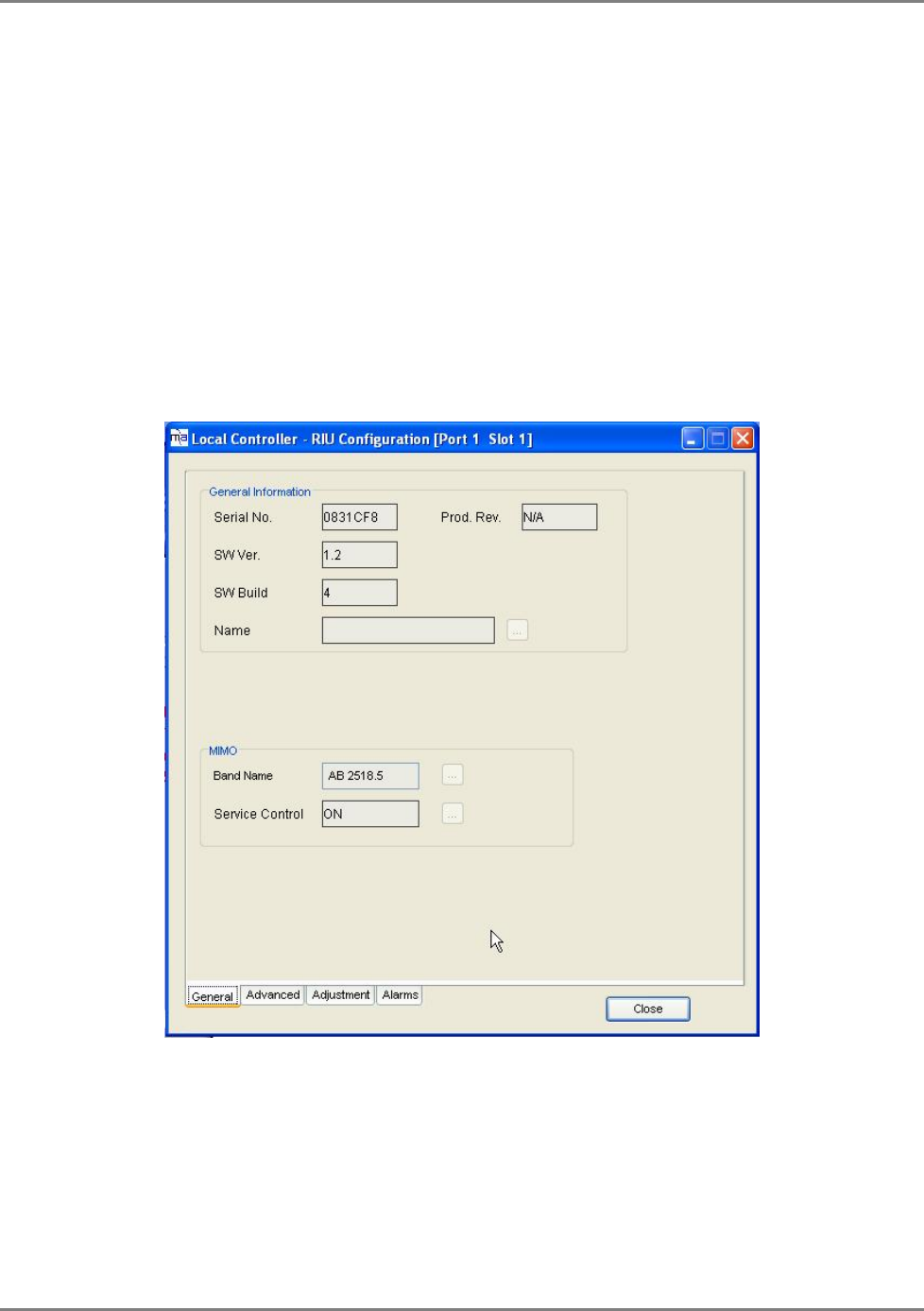
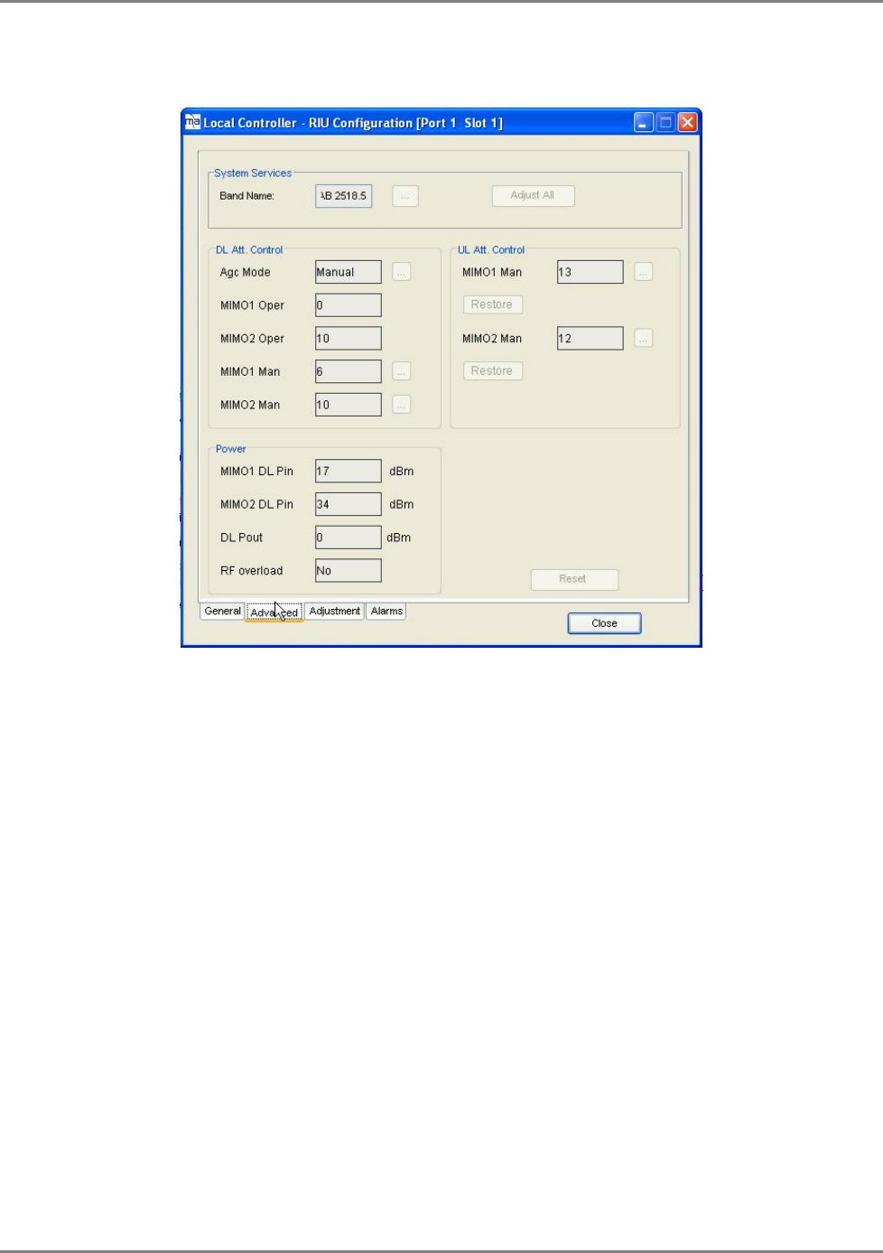
5.7.3 WIMAX (WRIU) RIU Configuration and Control
Each WRIU unit in the RIU is individually configured and controlled through a dedicated
configuration dialog. The main functions provided are:
• Setting gain control either automatically (AGC) or manually
• Resetting the BTSC
• Monitoring the downlink signal
To configure and control the WRIU
1. Double-click on the WRIU item in the Network Topology, or double-click on the specific
WRIU in the Device View. The WRIU configuration dialog appears with the General tab
displayed by default.
WiMAX System User Manual
MobileAccess WiMAX System User’s Guide 60
2. Click the Name Browse button and assign the WRIU a recognizable name (i.e. operator
name).
3. The DL gain may be set automatically (AGC) or manually (DCA – Digital Control
Attenuation). To control the DL gain control, set the DL AGC Mode in the Advanced tab:
• DL AGC Mode Status (Manual/auto) – Sets DL AGC mode.
Auto – automatic gain control to compensate for input power variations When enabled,
gain control is performed automatically;
Manual - DCA can be set manually (DL DCA Manual Override Value)
• MIMO 1/2 DCA Value – Digital Controlled Attenuation. An internal value that is reset
each time the adjustment procedure is performed
4. To reset the BTSC, click the Reset WRIU button in the Advanced tab.
WiMAX System User Manual
MobileAccess WiMAX System User’s Guide 61
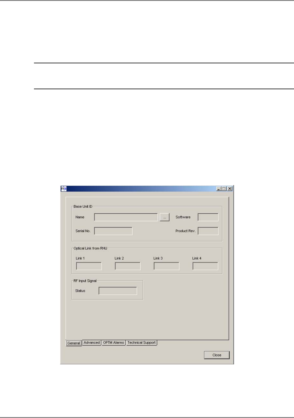
5.7.4 OPTM (BU) Configuration Dialog
Each OPTM unit in the BU is individually configured and controlled through a dedicated
configuration dialog.
Note: While most parameters are optional, each OPTM must be configured to interface with RIU
devices in installations that include RIUs. This is required, since by default OPTMs are set to
operate with passive interfaces.
The main functions provided are:
• Configuration of interface type on the BTS side (RIU or passive)
• Setting gain control either automatically (AGC) or manually
• Resetting the OPTM – required each time an RHU or MA 1200 add-on unit is added
• Monitoring the downlink signal
To configure and control the OPTM
1. Double-click on the OPTM item in the Network Topology, or double-click on the specific
OPTM in the Device View. The OPTM configuration dialog appears.
2. In the General tab, click the Name Browse button and assign the OPTM a recognizable
name that indicates the technology to which it interfaces.
WiMAX System User Manual
MobileAccess WiMAX System User’s Guide 62
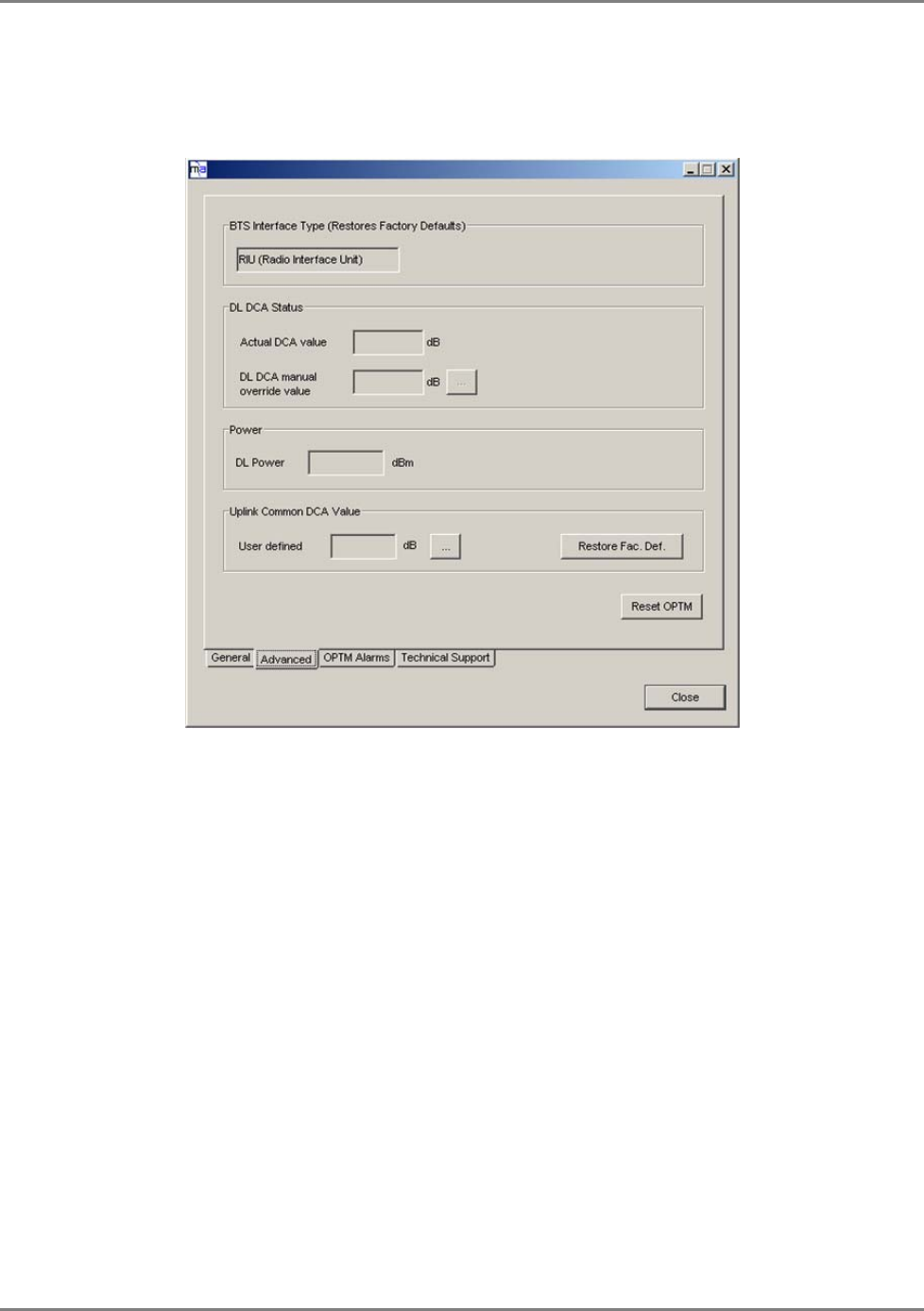
3. For sites in which RIUs are installed, configure the OPTM interface on the BTS side as RIU:
• Click the Advanced tab.
• Under BTS Interface Type, select RIU (default = Passive)
4. The DL gain may be set automatically (AGC) or manually (DCA). To control the DL gain
control, set the DL AGC Mode in the Advanced tab:
• Status (On/Off) – Sets DL AGC mode. When enabled, gain control is performed
automatically; when disabled (Off), DCA can be set manually (DL DCA Manual
Override Value)
• DL DCA Manual Override Value – manual DL gain control. This option becomes
available only when DLA AGC Mode (Status) is disabled.
Range – 0 to 31 dB
Actual value is displayed under DCA Value (dB).
5. To reset the OPTM, click the Reset OPTM button in the Advanced tab.
WiMAX System User Manual
MobileAccess WiMAX System User’s Guide 63
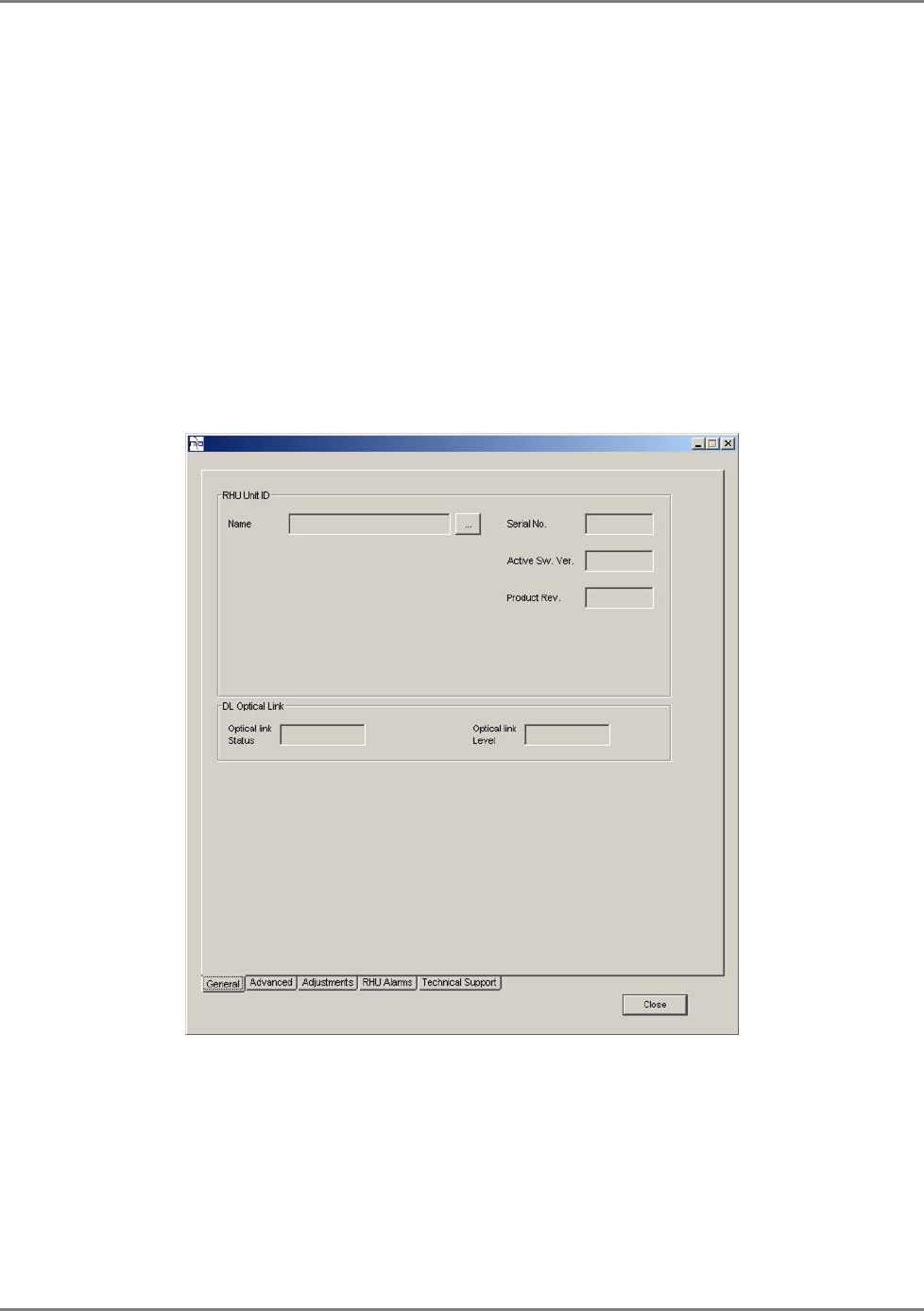
5.7.5 RHU Configuration Dialog
Each RHU is individually configured and controlled through a dedicated configuration dialog. The
main functions provided are:
• Controlling the services (on/off) and the DL output power to the antennas
• Setting the Uplink gain control
• Resetting the RHU
• Monitoring the signal
To configure and control the RHU
1. Double-click on the RHU item in the Network Topology, or double-click on the specific
RHU link
in the OPTM in the Device View. The RHU configuration dialog appears.
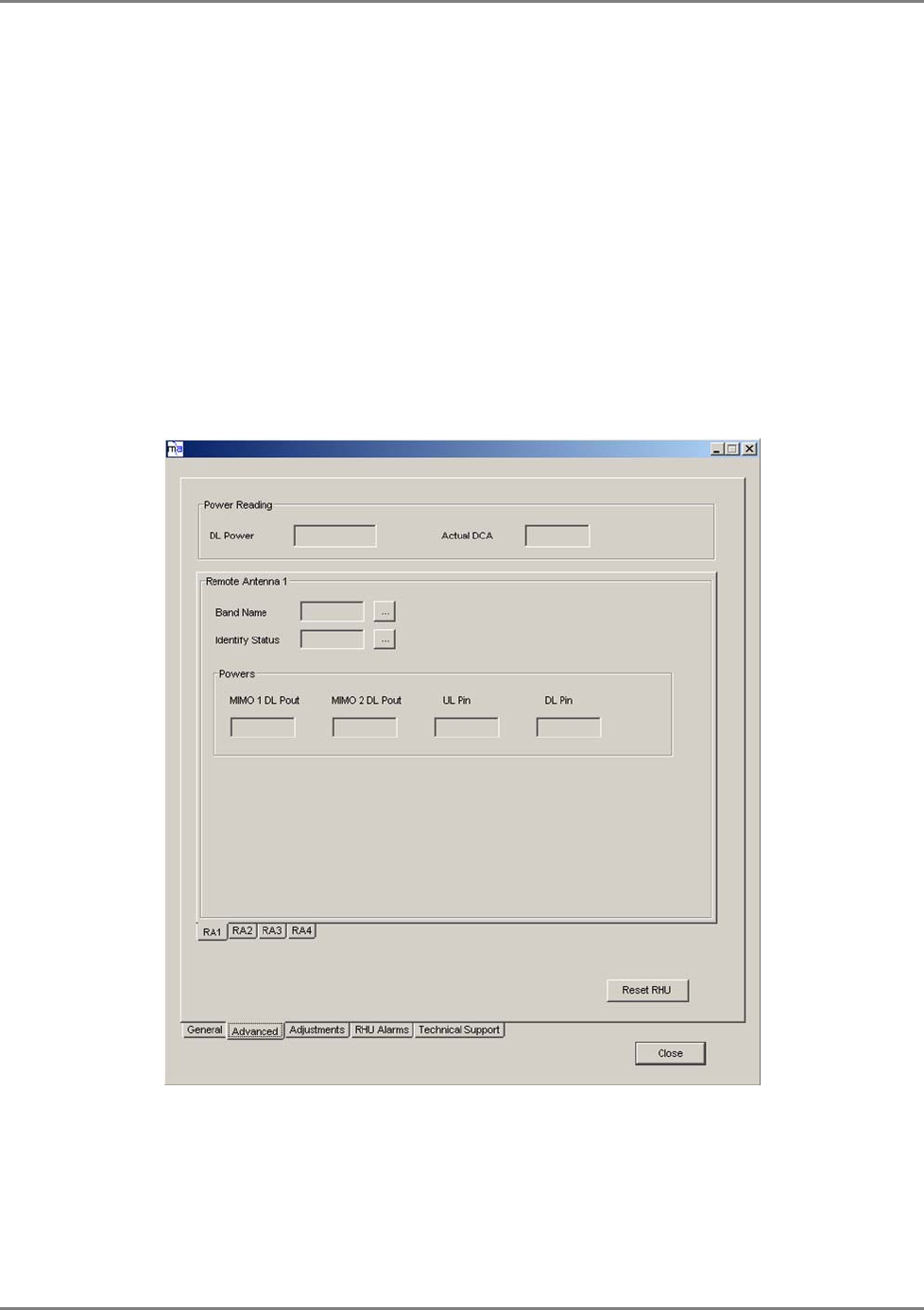
WiMAX System User Manual
MobileAccess WiMAX System User’s Guide 64
2. In the General tab, click the Name Browse button and assign the RHU a recognizable
name that indicates its supported services and location.
3. Configure the RHU band name choose from the following bands (the list below shows the
center frequency of each band) and click Set Band:
o AB: 2502-2535 MHz (2518.5 ±15MHz)
o CD: 2535-2568 MHz (2551.5 ±15MHz)
o EF: 2624-2657 MHz (2640.5 ±15MHz)
o GH: 2657-2690 MHz (2673.5 ±15MHz)
4. To disable one of the bands or change its power output to the antennas:
• Click the Advanced tab.
• Under Service Control, you may disable (OFF) the First Band or Second Band or
configure the DL Power reduction to optimize the power output to the antennas in
answer to changing site conditions
5. To control the UL AGC, set the UL AGC Mode (default = ON), in the Advanced tab for the
First Band and Second Band.
6. To reset the RHU, click the Reset RHU button in the Advanced tab.
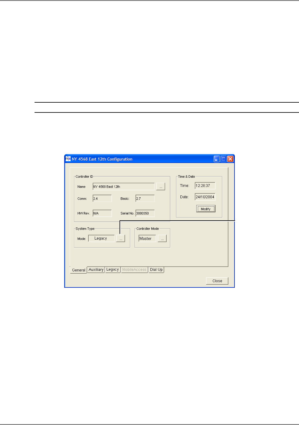
WiMAX System User Manual
MobileAccess WiMAX System User’s Guide 65
5.8 Configuring for Legacy Devices
The controller may host Legacy devices.
Follow the procedure in this section for a controller to
which Legacy devices are connected.
Legacy devices are
not
automatically identified by the controller. Each Legacy BU and the RHUs
that it hosts must be configured manually in order to be displayed in the Network Topology.
Note: In this type of configuration, RIUs are not supported.
To configure for Legacy devices
1. Double-click on the controller in the Network Topology pane to invoke the controller
configuration dialog.
2. In the General tab, under System Type, click the Mode Browse button and select
Legacy. The Legacy tab will be enabled (close and open the dialog if it does not open within
a few seconds).
Click to select
Legacy system
mode
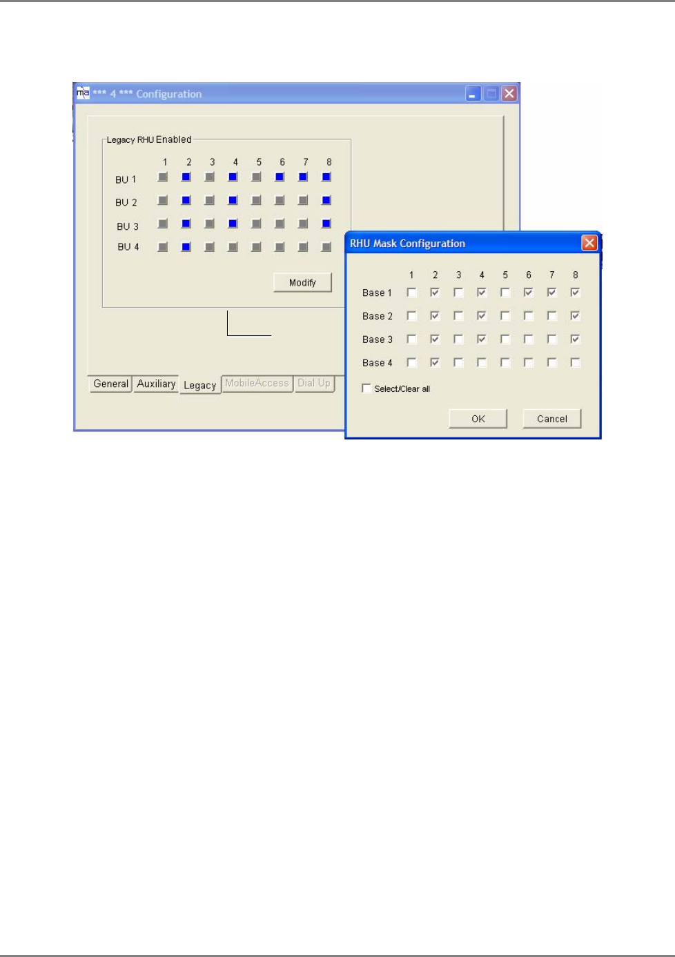
WiMAX System User Manual
MobileAccess WiMAX System User’s Guide 66
3. Click the Legacy tab. The dialog shows four rows: a row per BU and the RHUs it hosts. The
currently defined RHUs will be indicated by blue colored squares.
4. To change the configuration, click the Modify button.
5. For each configured BU (Base row), checkmark the ports to which RHUs are connected and
click OK.
This configuration will create a base line. The configured BUs and RHUs will now be
displayed in the Network Topology in red, yellow or green. BUs and RHUs to which
communication is lost, will be displayed in gray.
Base Units
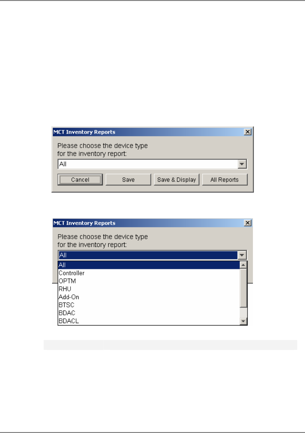
WiMAX System User Manual
MobileAccess WiMAX System User’s Guide 67
5.9 Reviewing the Inventory Reports
The user can view a list of the devices controlled via the connected controller in a tabular format
displayed as an Excel file. This option can be used to see at a glance, information on each
connected device. This includes versions, identification information and basic configuration
definitions. The file can be saved to a user selected location on the currently used computer.
To view the inventory report
1. In the MCT menu bar, click Inventory. The following dialog appears.
2. You may choose to view information on all or any one of the devices relevant to the
connected controller.
3. After choosing the device(s) on which to view the report, select the operation as follows:
Click the button.. To…
Save Save the information as an Excel file to a user selected location.
Save and Display Save the information and display the file.
All Reports Generate reports for all devices.
Cancel Exit this option.

WiMAX System User Manual
MobileAccess WiMAX System User’s Guide 68
5.10 What Next?
• Your topology is now configured in the MCT. Verify that all your devices are displayed in
the Network Topology. Check your configuration procedures.
• Remember, the controller must be configured to operate with Legacy or MobileAccess
devices, where Legacy devices must be defined.
• For MA 410 controller sites with RIU:
• Verify that the devices are displayed in green, red or yellow.
• Perform the adjustment procedure according to the
MA1000/2000 Commissioning Guide
.
• For controller sites without RIU: the devices should
all be
green.
• Perform the adjustment procedure according to
MA1000/2000 Commissioning Guide
.