Corning Optical Communication MA1500UHF MOBILEACCESS 1500 SYSTEM User Manual USERS MANUAL
Corning Optical Communication Wireless MOBILEACCESS 1500 SYSTEM USERS MANUAL
UserManual.wiki
>
Corning Optical Communication
>
MA1500UHF User Manual
USERS MANUAL
Navigation menu
Upload a User Manual
Namespaces
Wiki Guide
HTML
PDF
Info
Views
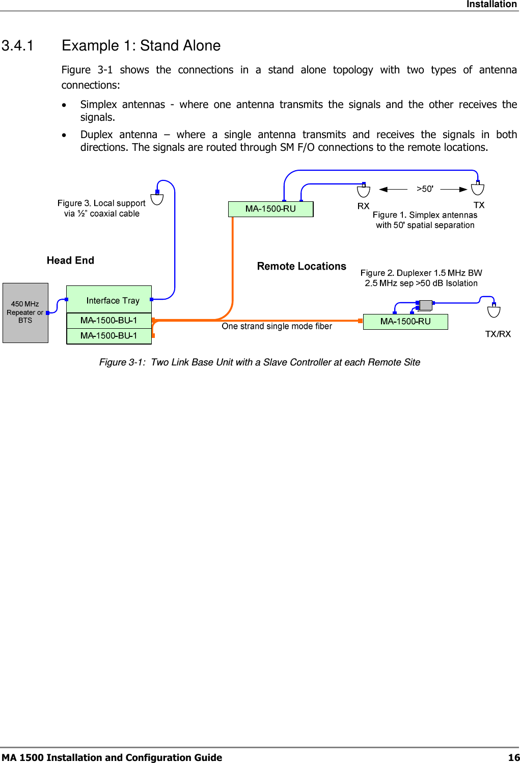
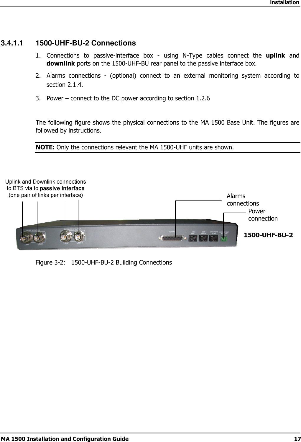
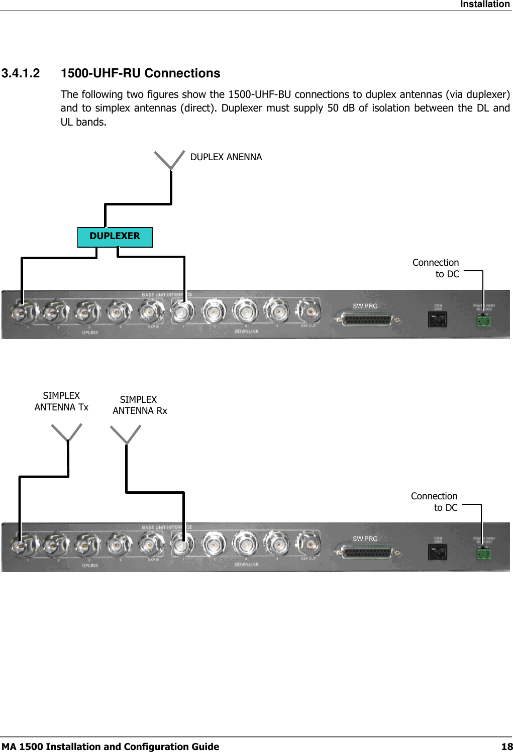
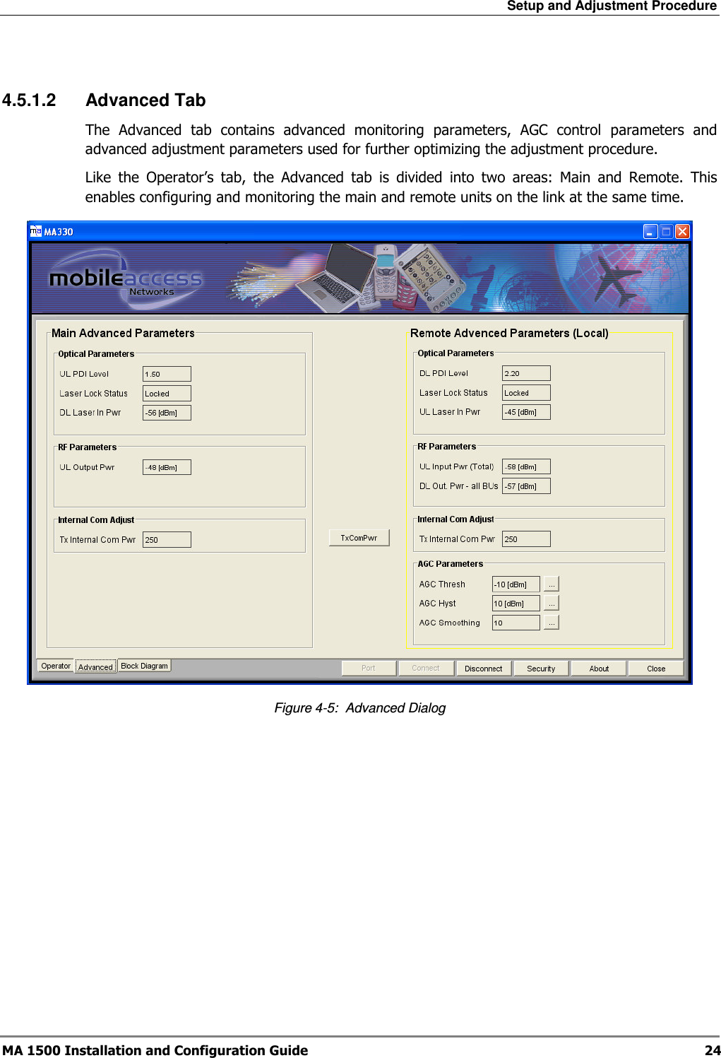
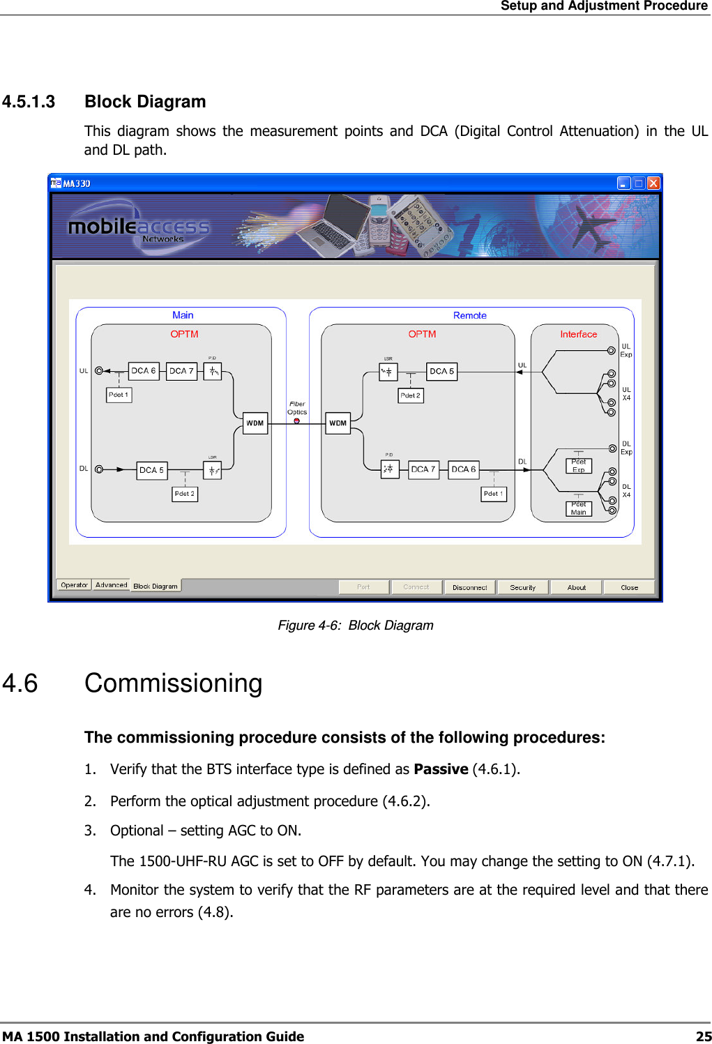
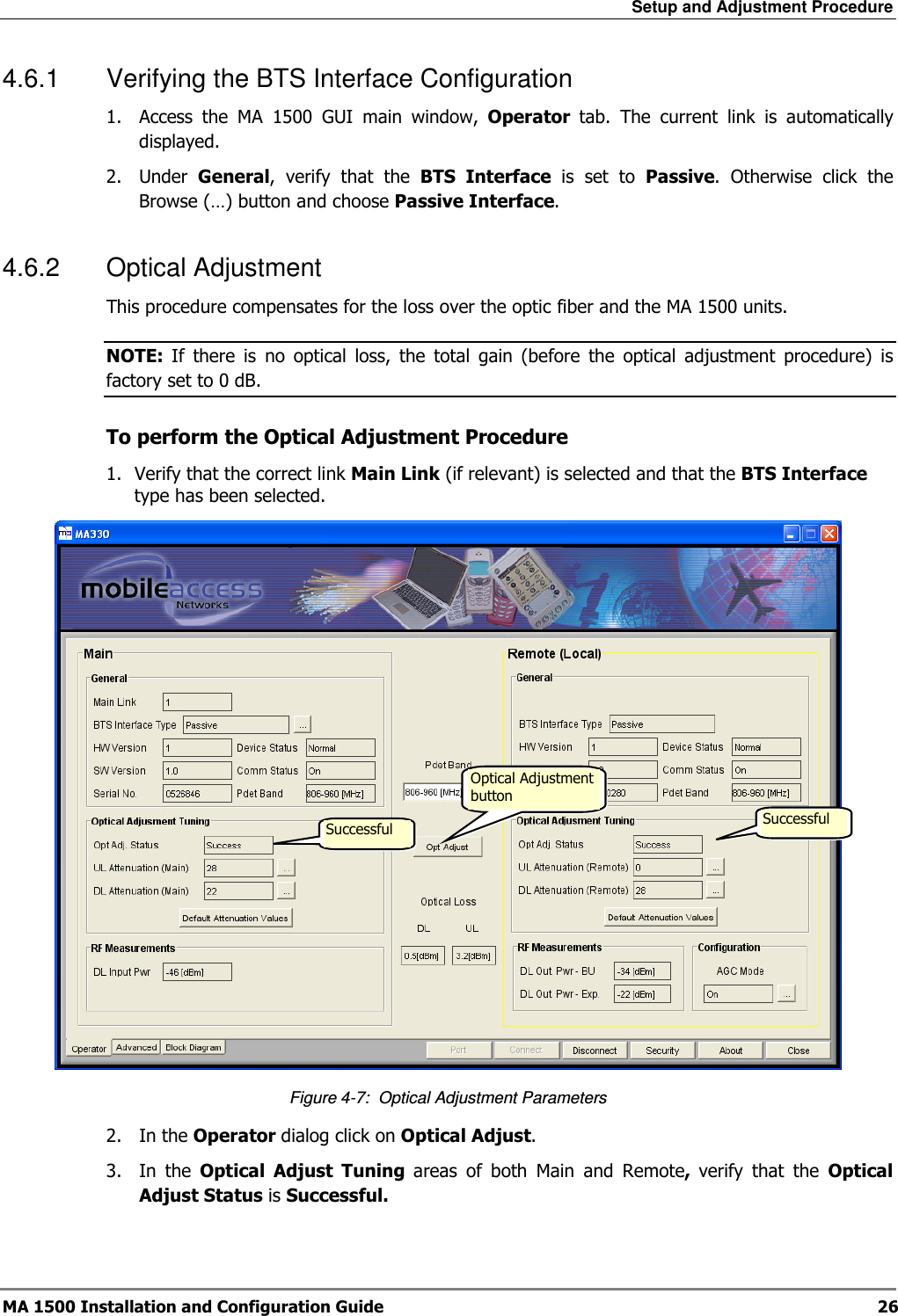
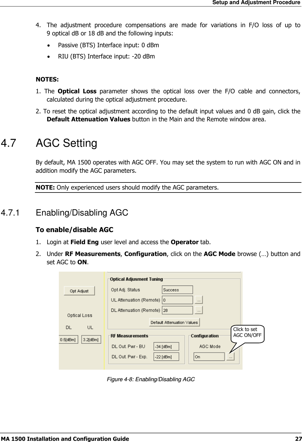
User Manual
Discussion / Help
Navigation