Corning Optical Communication MA1500UHF MOBILEACCESS 1500 SYSTEM User Manual USERS MANUAL
Corning Optical Communication Wireless MOBILEACCESS 1500 SYSTEM USERS MANUAL
USERS MANUAL

P/N: 709C003001
REV: A0
Date: 30-DEC-07
M
M
Mo
o
ob
b
bi
i
il
l
le
e
eA
A
Ac
c
cc
c
ce
e
es
s
ss
s
s
1
1
15
5
50
0
00
0
0
S
S
Sy
y
ys
s
st
t
te
e
em
m
m
Installation and Configuration Guide

Preface
MA 1500 Installation and Configuration Guide II
P
Pr
re
ef
fa
ac
ce
e
M
Ma
at
te
er
ri
ia
al
l
© COPYRIGHT 2006, MOBILEACCESS NETWORKS INC. ALL RIGHTS RESERVED.
MOBILEACCESSTM IS A REGISTERED TRADEMARK OF MOBILEACCESS. THIS DOCUMENT CONTAINS OTHER TRADEMARKS, TRADE NAMES AND
SERVICE MARKS OF MOBILEACCESS AND OTHER ORGANIZATIONS, ALL OF WHICH ARE THE PROPERTY OF THEIR RESPECTIVE OWNERS.
THIS DOCUMENT CONTAINS CONFIDENTIAL AND PROPRIETARY INFORMATION OF MOBILEACCESS AND MAY NOT BE COPIED, TRANSMITTED, STORED
IN A RETRIEVAL SYSTEM OR REPRODUCED IN ANY FORMAT OR MEDIA, IN WHOLE OR IN PART, WITHOUT THE PRIOR WRITTEN CONSENT OF
MOBILEACCESS. INFORMATION CONTAINED IN THIS DOCUMENT SUPERSEDES ANY PREVIOUS MANUALS, GUIDES, SPECIFICATIONS, DATA SHEETS OR
OTHER INFORMATION THAT MAY HAVE BEEN PROVIDED OR MADE AVAILABLE TO THE USER.
THIS DOCUMENT IS PROVIDED FOR INFORMATIONAL PURPOSES ONLY, AND MOBILEACCESS DOES NOT WARRANT OR GUARANTEE THE ACCURACY,
ADEQUACY, QUALITY, VALIDITY, COMPLETENESS OR SUITABILITY FOR ANY PURPOSE OF THE INFORMATION CONTAINED IN THIS DOCUMENT.
MOBILEACCESS RESERVES THE RIGHT TO MAKE UPDATES, IMPROVEMENTS AND ENHANCEMENTS TO THIS DOCUMENT AND THE PRODUCTS TO
WHICH IT RELATES AT ANY TIME WITHOUT PRIOR NOTICE TO THE USER. MOBILEACCESS MAKES NO WARRANTIES, EXPRESS OR
IMPLIED, INCLUDING, WITHOUT LIMITATION, THOSE OF MERCHANTABILITY AND FITNESS FOR A PARTICULAR PURPOSE,
WITH RESPECT TO THIS DOCUMENT OR ANY INFORMATION CONTAINED HEREIN.
MobileAccess, 8391 Old Courthouse Road, Suite 300, Vienna, VA 22182
Tel: (866)436-9266, (703)848-0200 TAC: (800)787-1266, Fax: (703)848-0280
http://www.MobileAccess.com

Preface
MA 1500 Installation and Configuration Guide III
Policy for Warrantee and Repair
MOBILEACCESS TESTS AND INSPECTS ALL ITS PRODUCTS TO VERIFY THEIR QUALITY AND RELIABILITY. MOBILEACCESS USES EVERY REASONABLE
PRECAUTION TO ENSURE THAT EACH UNIT MEETS THEIR DECLARED SPECIFICATIONS BEFORE SHIPMENT. CUSTOMERS SHOULD ADVISE THEIR
INCOMING INSPECTION, ASSEMBLY, AND TEST PERSONNEL ABOUT THE PRECAUTIONS REQUIRED IN HANDLING AND TESTING OUR PRODUCTS. MANY
OF THESE PRECAUTIONS CAN BE FOUND IN THIS MANUAL.
THE PRODUCTS ARE COVERED BY THE FOLLOWING WARRANTIES:
General Warranty
MOBILEACCESS WARRANTS TO THE ORIGINAL PURCHASER ALL STANDARD PRODUCTS SOLD BY MOBILEACCESS TO BE FREE OF DEFECTS IN
MATERIAL AND WORKMANSHIP FOR ONE (1) YEAR FROM DATE OF SHIPMENT FROM MOBILEACCESS. DURING THE WARRANTY PERIOD,
MOBILEACCESS WILL REPAIR OR REPLACE ANY PRODUCT THAT MOBILEACCESS PROVES TO BE DEFECTIVE. THIS WARRANTY DOES NOT APPLY TO
ANY PRODUCT THAT HAS BEEN SUBJECT TO ALTERATION, ABUSE, IMPROPER INSTALLATION OR APPLICATION, ACCIDENT, ELECTRICAL OR
ENVIRONMENTAL OVER-STRESS, NEGLIGENCE IN USE, STORAGE, TRANSPORTATION OR HANDLING.
Specific Product Warranty Instructions
ALL MOBILEACCESS PRODUCTS ARE WARRANTED AGAINST DEFECTS IN WORKMANSHIP, MATERIALS AND CONSTRUCTION, AND TO NO FURTHER
EXTENT. ANY CLAIM FOR REPAIR OR REPLACEMENT OF UNITS FOUND TO BE DEFECTIVE ON INCOMING INSPECTION BY A CUSTOMER MUST BE MADE
WITHIN 30 DAYS OF RECEIPT OF SHIPMENT, OR WITHIN 30 DAYS OF DISCOVERY OF A DEFECT WITHIN THE WARRANTY PERIOD.
THIS WARRANTY IS THE ONLY WARRANTY MADE BY MOBILEACCESS AND IS IN LIEU OF ALL OTHER WARRANTIES, EXPRESSED OR IMPLIED.
MOBILEACCESS SALES AGENTS OR REPRESENTATIVES ARE NOT AUTHORIZED TO MAKE COMMITMENTS ON WARRANTY RETURNS.
Returns
IN THE EVENT THAT IT IS NECESSARY TO RETURN ANY PRODUCT AGAINST ABOVE WARRANTY, THE FOLLOWING PROCEDURE SHALL BE FOLLOWED:
1. RETURN AUTHORIZATION IS TO BE RECEIVED FROM MOBILEACCESS PRIOR TO RETURNING ANY UNIT. ADVISE MOBILEACCESS OF THE MODEL,
SERIAL NUMBER, AND DISCREPANCY. THE UNIT MAY THEN BE FORWARDED TO MOBILEACCESS, TRANSPORTATION PREPAID. DEVICES RETURNED
COLLECT OR WITHOUT AUTHORIZATION MAY NOT BE ACCEPTED.
2. PRIOR TO REPAIR, MOBILEACCESS WILL ADVISE THE CUSTOMER OF OUR TEST RESULTS AND ANY CHARGES FOR REPAIRING CUSTOMER-CAUSED
PROBLEMS OR OUT-OF-WARRANTY CONDITIONS ETC.
3. REPAIRED PRODUCTS ARE WARRANTED FOR THE BALANCE OF THE ORIGINAL WARRANTY PERIOD, OR AT LEAST 90 DAYS FROM DATE OF
SHIPMENT.
Limitations of Liabilities
MOBILEACCESS'S LIABILITY ON ANY CLAIM, OF ANY KIND, INCLUDING NEGLIGENCE FOR ANY LOSS OR DAMAGE ARISING FROM, CONNECTED WITH,
OR RESULTING FROM THE PURCHASE ORDER, CONTRACT, QUOTATION, OR FROM THE PERFORMANCE OR BREACH THEREOF, OR FROM THE DESIGN,
MANUFACTURE, SALE, DELIVERY, INSTALLATION, INSPECTION, OPERATION OR USE OF ANY EQUIPMENT COVERED BY OR FURNISHED UNDER THIS
CONTACT, SHALL IN NO CASE EXCEED THE PURCHASE PRICE OF THE DEVICE WHICH GIVES RISE TO THE CLAIM.
EXCEPT AS EXPRESSLY PROVIDED HEREIN, MOBILEACCESS MAKES NO WARRANTY, EXPRESSED OR IMPLIED, WITH
RESPECT TO ANY GOODS, PARTS AND SERVICES PROVIDED IN CONNECTION WITH THIS AGREEMENT INCLUDING, BUT NOT
LIMITED TO, THE IMPLIED WARRANTIES OF MERCHANTABILITY AND FITNESS FOR A PARTICULAR PURPOSE. MOBILEACCESS
SHALL NOT BE LIABLE FOR ANY OTHER DAMAGE INCLUDING, BUT NOT LIMITED TO, INDIRECT, SPECIAL OR CONSEQUENTIAL
DAMAGES ARISING OUT OF OR IN CONNECTION WITH FURNISHING OF GOODS, PARTS AND SERVICE HEREUNDER, OR THE
PERFORMANCE, USE OF, OR INABILITY TO USE THE GOODS, PARTS AND SERVICE.

Preface
MA 1500 Installation and Configuration Guide IV
Reporting Defects
THE UNITS WERE INSPECTED BEFORE SHIPMENT AND FOUND TO BE FREE OF MECHANICAL AND ELECTRICAL DEFECTS.
EXAMINE THE UNITS FOR ANY DAMAGE THAT MAY HAVE BEEN CAUSED IN TRANSIT. IF DAMAGE IS DISCOVERED, FILE A CLAIM WITH THE FREIGHT
CARRIER IMMEDIATELY. NOTIFY MOBILEACCESS AS SOON AS POSSIBLE.
NOTE: KEEP ALL PACKING MATERIAL UNTIL YOU HAVE COMPLETED THE INSPECTION
WARNING: TO COMPLY WITH FCC RF EXPOSURE COMPLIANCE REQUIREMENTS, ANTENNAS USED FOR THIS PRODUCT MUST BE FIXED MOUNTED
ON INDOOR PERMANENT STRUCTURES, PROVIDING A SEPARATION DISTANCE OF AT LEAST 20 CM FROM ALL PERSONS DURING NORMAL OPERATION.
WARNING: ANTENNA GAIN SHOULD NOT EXCEED 10 dBI.
WARNING: EACH INDIVIDUAL ANTENNA USED FOR THIS TRANSMITTER MUST BE INSTALLED TO PROVIDE A MINIMUM SEPARATION DISTANCE OF 20
CM OR MORE FROM ALL PERSONS AND MUST NOT BE CO-LOCATED WITH ANY OTHER ANTENNA FOR MEETING RF EXPOSURE REQUIREMENTS.
WARNING: THE DESIGN OF THE ANTENNA INSTALLATION NEEDS TO BE IMPLEMENTED IN SUCH A WAY SO AS TO ENSURE RF RADIATION SAFETY
LEVELS AND NON-ENVIRONMENTAL POLLUTION DURING OPERATION.
ATTENTION:
COMPLIANCE WITH RF SAFETY REQUIREMENTS:
- MOBILEACCESS™ PRODUCTS HAVE NO INHERENT SIGNIFICANT RF RADIATION.
- THE RF LEVEL ON THE DOWN LINK IS VERY LOW AT THE REMOTE UNITS (RHUS) DOWNLINK PORTS. THEREFORE, THERE IS NO DANGEROUS RF
RADIATION WHEN THE ANTENNA IS NOT CONNECTED.
Laser Safety
FIBER OPTIC PORTS OF THE MOBILEACCESS 15000 SYSTEM MODULES EMIT INVISIBLE LASER RADIATION AT THE 1310/1550 NM WAVELENGTH
WINDOW.
TO AVOID EYE INJURY NEVER LOOK DIRECTLY INTO THE OPTICAL PORTS, PATCHCORDS OR OPTICAL CABLES. DO NOT STARE INTO BEAM OR VIEW
DIRECTLY WITH OPTICAL INSTRUMENTS. ALWAYS ASSUME THAT OPTICAL OUTPUTS ARE ON.
ONLY TECHNICIANS FAMILIAR WITH FIBER OPTIC SAFETY PRACTICES AND PROCEDURES SHOULD PERFORM OPTICAL FIBER CONNECTIONS AND
DISCONNECTIONS OF THE MOBILEACCESS 1500 DEVICES AND THE ASSOCIATED CABLES.
THE MOBILEACCESS 1500 COMPLIES WITH 21 CFR 1040.10 AND 1040.11 EXCEPT FOR DEVIATIONS PURSUANT TO LASER NOTICE NO. 50 (JULY
26, 2001) & IEC 60825-1, AMENDMENT 2 (JAN. 2001).
Care of Fiber Optic Connectors
DO NOT REMOVE THE PROTECTIVE COVERS ON THE FIBER OPTIC CONNECTORS UNTIL A CONNECTION IS READY TO BE MADE. DO NOT LEAVE
CONNECTORS UNCOVERED WHEN NOT CONNECTED.
THE TIP OF THE FIBER OPTIC CONNECTOR SHOULD NOT COME INTO CONTACT WITH ANY OBJECT OR DUST.
REFER TO THE CLEANING PROCEDURE FOR INFORMATION ON THE CLEANING OF THE FIBER TIP.
CAUTION – USE OF CONTROLS OR ADJUSTMENTS OR PERFORMANCE OF PROCEDURES OTHER THAN
THOSE SPECIFIED HEREIN MAY RESULT IN HAZARDOUS RADIATION EXPOSURE

Preface
MA 1500 Installation and Configuration Guide V
Standards and Certification
MobileAccess products have met the approvals of the following certifying organizations:
ISO 9001
For US: UL, FCC – 15, 90
FDA/CE 21 CFR 1040.10 and 1040.11 except for deviations pursuant to laser notice no. 50
(July 26, 2001) and IEC 60825-1,Amendment 2 (Jan. 2001)
FCC Certification
NOTE: This equipment has been tested and found to comply with the limits for a Class B digital
device, pursuant to Part 15 of the FCC Rules. These limits are designed to provide reasonable
protection against harmful interference in a residential installation. This equipment generates,
uses and can radiate radio frequency energy and, if not installed and used in accordance with
the instructions, may cause harmful interference to radio communications. However, there is no
guarantee that interference will not occur in a particular installation. If this equipment does
cause harmful interference to radio or television reception, which can be determined by turning
the equipment off and on, the user is encouraged to try to correct the interference by one or
more of the following measures:
• Reorient or relocate the receiving antenna.
• Increase the separation between the equipment and receiver.
• Connect the equipment into an outlet on a circuit different from that to which the receiver is
connected.
• Consult the dealer or an experienced radio/TV technician for help.
WARNING! Changes or modifications to this equipment not expressly approved by the party responsible
for compliance MobileAccess Ltd. could void the user’s authority to operate the equipment.

Preface
MA 1500 Installation and Configuration Guide VI
About This Guide
This user guide provides a description of the MA-1500 system and instructions for installing the
systems. The MA 1500 is an RF distribution system that can be used in conjunction with the MA
1000/2000 systems.
Revision History
The revision history for this document is shown in Table
1-1.
Table
1-1: Revision history
P/N Date Description
709C003001 30-DEC-07 Initial version

Preface
MA 1500 Installation and Configuration Guide VII
List of Acronyms
AGC Automatic Gain Control
BDA Bi-Directional Amplifier
BTS Base Transceiver Station
BTSC Base Transceiver Station Conditioner
BU Base Unit
DL Downlink
RHU Remote Hub Unit
RIU Radio Interface Unit
SNR Signal to Noise Ratio
UL Uplink
VDC Volts Direct Current

Preface
MA 1500 Installation and Configuration Guide VIII
Table of Contents
Preface Material ........................................................................................................................II
Policy for Warrantee and Repair.........................................................................................................III
Laser Safety ..................................................................................................................................... IV
Care of Fiber Optic Connectors .......................................................................................................... IV
Standards and Certification................................................................................................................. V
About This Guide .............................................................................................................................. VI
Revision History ................................................................................................................................ VI
List of Acronyms ..............................................................................................................................VII
Table of Contents............................................................................................................................VIII
1 Introduction to the MA 1500 System.................................................................................1
1.1 System Architecture .....................................................................................................................2
1.2 System Operation and Capabilities ................................................................................................3
1.2.1 Commissioning ...................................................................................................................3
1.2.2 Fault Detection and Alarm Reporting ...................................................................................3
1.2.3 RF Signal Connections ........................................................................................................3
1.2.4 Optical Signal Connections ..................................................................................................3
1.2.5 Optical Signal Level Adjustment...........................................................................................4
1.2.6 Powering ...........................................................................................................................4
1.2.7 Mounting ...........................................................................................................................4
1.3 MA 1500 Models ..........................................................................................................................4
2 MA-1500 system Elements ................................................................................................5
2.1 1500-BU Unit Description .............................................................................................................5
2.1.1 Primary Functions...............................................................................................................6
2.1.2 1500 Base Unit Front Panel .................................................................................................6
2.1.3 1500-UHF-BU Rear Panel ....................................................................................................8
2.1.4 1500-UHF-BU Dry-Contact Alarms .......................................................................................8
2.2 1500-UHF-RU Unit Description......................................................................................................9
2.2.1 Primary Functions...............................................................................................................9
2.2.2 1500-UHF-RU Front Panel ...................................................................................................9
2.2.3 1500-UHF-RU Rear Panel ..................................................................................................11

Preface
MA 1500 Installation and Configuration Guide IX
3 Installation........................................................................................................................12
3.1 Overview...................................................................................................................................12
3.2 Pre-installation Instructions ........................................................................................................12
3.2.1 Installation Overview ........................................................................................................12
3.2.2 Provided Accessories ........................................................................................................12
3.2.3 Unpacking and Inspection .................................................................................................13
3.2.4 Rack Installation Instructions ............................................................................................13
3.2.5 Fiber Optic Rules ..............................................................................................................14
3.2.6 RF Rules ..........................................................................................................................14
3.3 Power Consumption, Connections and Power Supplies .................................................................15
3.3.1 Power Safety Instructions .................................................................................................15
3.3.2 Power Requirements.........................................................................................................15
3.3.3 Circuit Breakers ................................................................................................................15
3.4 Installation Procedure ................................................................................................................15
3.4.1 Example 1: Stand Alone....................................................................................................16
3.4.1.1 1500-UHF-BU-2 Connections.................................................................................17
3.4.1.2 1500-UHF-RU Connections....................................................................................18
4 Setup and Adjustment Procedure...................................................................................19
4.1 Overview...................................................................................................................................19
4.2 Software Installation ..................................................................................................................19
4.3 How to Use the MA 1500 Setup Tool ...........................................................................................19
4.4 Installing and Launching the Application......................................................................................20
4.4.1 Installation and Connection...............................................................................................20
4.4.2 Launching the Application and Logging In..........................................................................21
4.5 Navigating MA 1500 GUI ............................................................................................................22
4.5.1.1 Operator Tab .......................................................................................................23
4.5.1.2 Advanced Tab ......................................................................................................24
4.5.1.3 Block Diagram......................................................................................................25
4.6 Commissioning ..........................................................................................................................25
4.6.1 Verifying the BTS Interface Configuration ..........................................................................26
4.6.2 Optical Adjustment ...........................................................................................................26
4.7 AGC Setting...............................................................................................................................27
4.7.1 Enabling/Disabling AGC.....................................................................................................27
4.7.2 Changing AGC Settings .....................................................................................................28
4.8 Monitoring.................................................................................................................................29
4.8.1 Monitoring System Status .................................................................................................29
4.8.2 Monitoring the RF Parameters ...........................................................................................30

Preface
MA 1500 Installation and Configuration Guide X
4.8.3 Monitoring the Optical Parameters.....................................................................................31
4.9 Viewing Versions........................................................................................................................32
4.10 Security Management.................................................................................................................32
4.10.1 Authorization Levels and Passwords...................................................................................32

MA 450 Installation and Configuration Guide 1
1 I
In
nt
tr
ro
od
du
uc
ct
ti
io
on
n
t
to
o
t
th
he
e
M
MA
A
1
15
50
00
0
S
Sy
ys
st
te
em
m
MA 1500 provides a cost effective solution for extending 450 MHz signal from a single BTS
location to remote locations, up to 20 Km away, over SM F/O connections.
Simplex RF inputs and outputs support a wide variety of channel assignments, while maintaining
the service integrity via highly linear amplifiers. Intuitive GUI software enables end-to-end setup
and adjustment of the coverage to minimize interaction with outdoor signals.
The system can support two independent links, where each link can support:
• A different service
• A sector – where two links are required for two sectors of the same service
The MA-1500 system is based on the following elements:
• 1500-UHF-BU – A 1500-UHF-BU unit is installed, adjacent to the BTS location. It
performs the RF to optic signal conversion at the BTS side and transmits the services to
the remote location(s) where 1500-UHF-RU units are installed.
• 1500-UHF-RU – A 1500-UHF-RU is installed at each remote location. This unit
reconverts the signals received over the optic fiber to RF and distributes the services to
the connected antennas.
• MA-1500 GUI Tool – Intuitive GUI used for setting up, adjusting and monitoring the
MA 1500 system. (The MA-1500 GUI is the same GUI tool as for the MA-330 – described
in Chapter 4
Introduction to the MA 1500 System
MA 1500 Installation and Configuration Guide 2
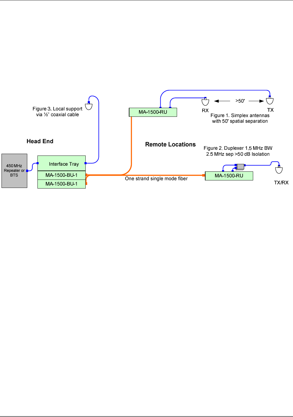
1.1 System Architecture
At the Main building, the 1500-UHF-BU interfaces to the BTS via passive interface. It converts
the RF signal received from the BTS to an optic signal and transmits it over SM optic fiber to the
MA 1500 Remote. At the Remote buildings, the 1500-UHF-RU reconverts the received RF signal
to an optic signal and routes the RF signals to the antennas.
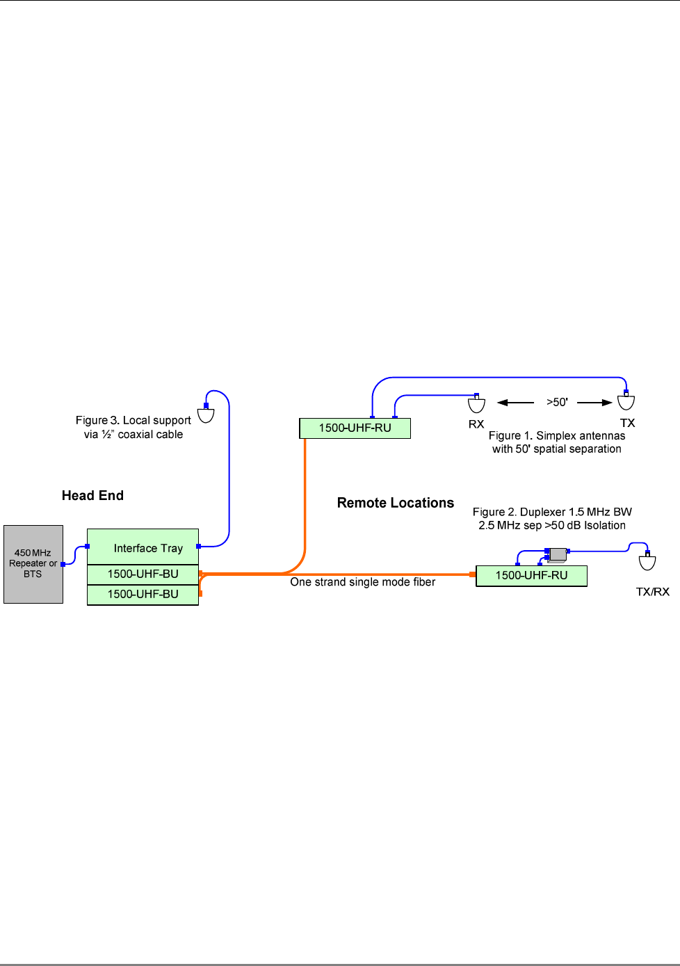
The MA-1500 system provides flexible solutions for two types of antennas – simplex and duplex.
Both solutions are illustrated in Figure
1-1.
• Simplex antennas – these type of antennas are connected directly to the remote unit: one
for the Rx and one for the Tx signal.
• Duplex – these antennas are connected to the remote unit via a duplexer. One antenna
both receives and transmits signals. Up to four duplex antennas can be connected to each
remote unit.
Figure
1-1. MA 1500 Installations

Introduction to the MA 1500 System
MA 1500 Installation and Configuration Guide 3
1.2 System Operation and Capabilities
1.2.1 Commissioning
The MA-1500 system can be configured and adjusted according to the specific installation. The
procedure is performed through intuitive GUI run via a local connection to either the 1500-UHF-
BU or to the corresponding 1500-UHF-RU unit (
Chapter
4 Setup and Adjustment Procedure
).
NOTE: The setup and adjustment procedures are end-to-end, meaning that both 1500-UHF-BU
and the 1500-UHF-RU on the corresponding link can be adjusted by connecting to either units.
1.2.2 Fault Detection and Alarm Reporting
The MA 1500 units provides the following types of fault detection:
• Front Panel LED
• Dry-contact auxiliary - 1500-UHF-BU only. Two normally closed connections used for
reporting to an external alarm system when the optic signal level is not within the required
range.
• GUI monitoring on each link, through a local connection to either the 1500-UHF-BU or 1500-
UHF-RU unit of the corresponding link
1.2.3 RF Signal Connections
1500-UHF-BU - The RF signal connections between the 1500-UHF-BU and the BTS interface
(RIU or passive interface) are supported through N-type female connectors mounted on the
1500-UHF-BU rear panel: one connector for each forward path coax cable and one for each
reverse path coax cable (two connectors for one link, four connectors for two links).
1500-UHF-RU - The RF signal connections between the 1500-UHF-RU and the antennas are
supported through four pairs of N-type female connectors mounted on the 1500-UHF-BU-2 rear
panel. One connector is used for connecting the forward path coaxial cable and one connector
for connecting the reverse path coaxial cable.
1.2.4 Optical Signal Connections
• 1500-UHF-BU - one or two optical connections, SC/APC, on the front panel, corresponding
to the number of links supported by the MA 1500 model
• 1500-UHF-RU – single optical link, SC/APC, on the front panel

Introduction to the MA 1500 System
MA 1500 Installation and Configuration Guide 4
1.2.5 Optical Signal Level Adjustment
The 1500-UHF-BU and Remote units are equipped with digital attenuators for adjusting the
forward and reverse optic signal level. The attenuators are adjusted through the GUI.
1.2.6 Powering
The MA 1500-UHF-BU and 1500-UHF-RU is powered by a 20 to 48 VDC power which is supplied
through a standard power connection to the rear panel.
1.2.7 Mounting
The MA 1500 units are specifically designed for 19” rack-mount installations. When installed, the
front panels of the units are flush with the front of the rack.
1.3 MA 1500 Models
Table
1-1: MobileAccess™ 1500 Models
MobileAccess 1500 system units
1500-UHF-BU-1
Base Unit, 422-512 MHz supporting 1 Remote Unit
1500-UHF-BU-2
Base Unit, 422-512 MHz supporting 2 Remote Units
1500-UHF-RU
Remote Unit, 422-512 MHz
1500-VHF-BU-1
Not yet available
1500-VHF-BU-2
Not yet available
1500-VHF-RU Not yet available
MA 450 Installation and Configuration Guide 5
2 M
MA
A-
-1
15
50
00
0
s
sy
ys
st
te
em
m
E
El
le
em
me
en
nt
ts
s
This chapter describes each of the system elements: MA 1500-BU and 1500-UHF-RU The
description includes front and rear panel ports, LEDs and specific connections according to the
basic installation types such as connection to one or two remote locations.
2.1 1500-BU Unit Description
1500-UHF-BU is available in two models:
• 1500-UHF-BU-2 (Dual link) – The unit contains two (identical and independent) RF to
optic conversion modules, enabling it to connect to two different sites (buildings) and
support two (different or same) services.
• 1500-UHF-BU-1 (Single link) – The unit contains a single RF to optic conversion module,
enabling it to connect to a single remote site (building) and support a single service.
NOTE: The modules in the single-link and in the dual-link MA-1500-BUs are the same. All
references made in this manual to 1500-UHF-BU refers to 1500-UHF-BU-1 and 1500-UHF-BU-2).
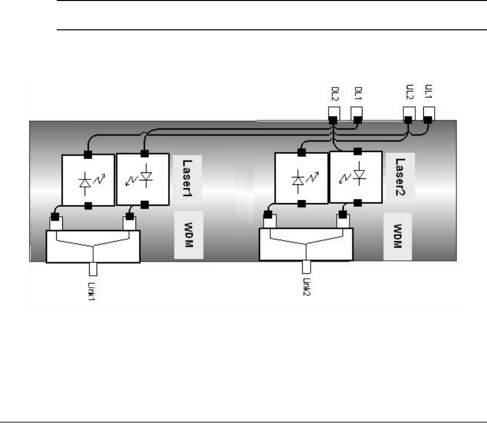
The following figure shows the 1500-UHF-BU-2 block diagram (note that the two units are
completely separate).
Figure 2-1 1500-UHF-BU-2 Block Diagram
MA-1500 system Elements
MA 1500 Installation and Configuration Guide 6
2.1.1 Primary Functions
The 1500-UHF-BU unit interfaces to the service signal source (BTS) through passive interface,
performs RF to optic (on the DL) and transmits the service and control signals over optic fiber to
the remote location(s).
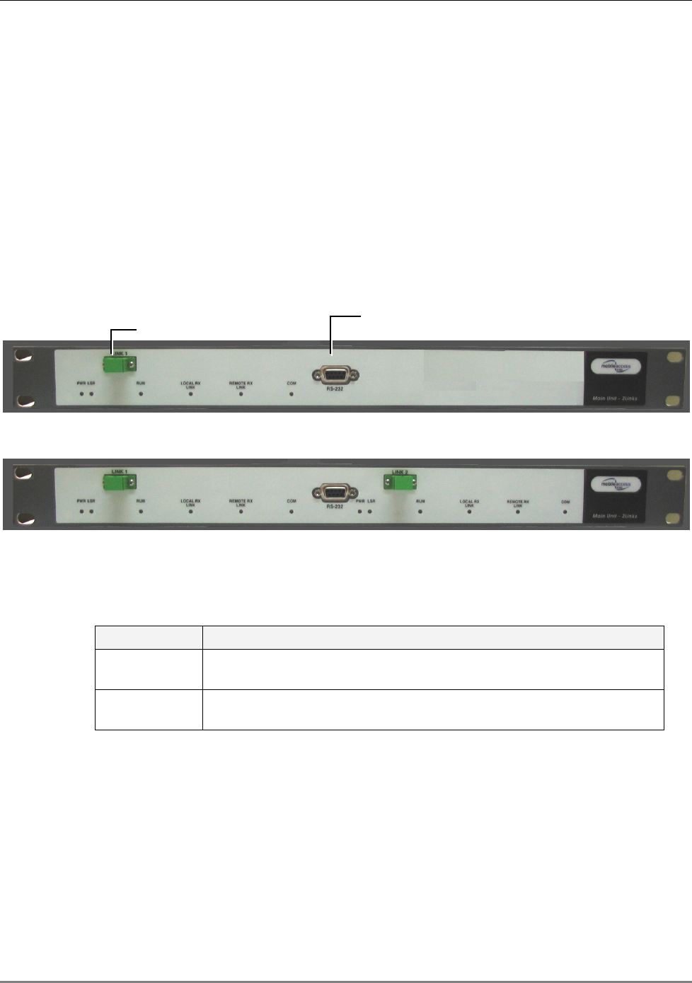
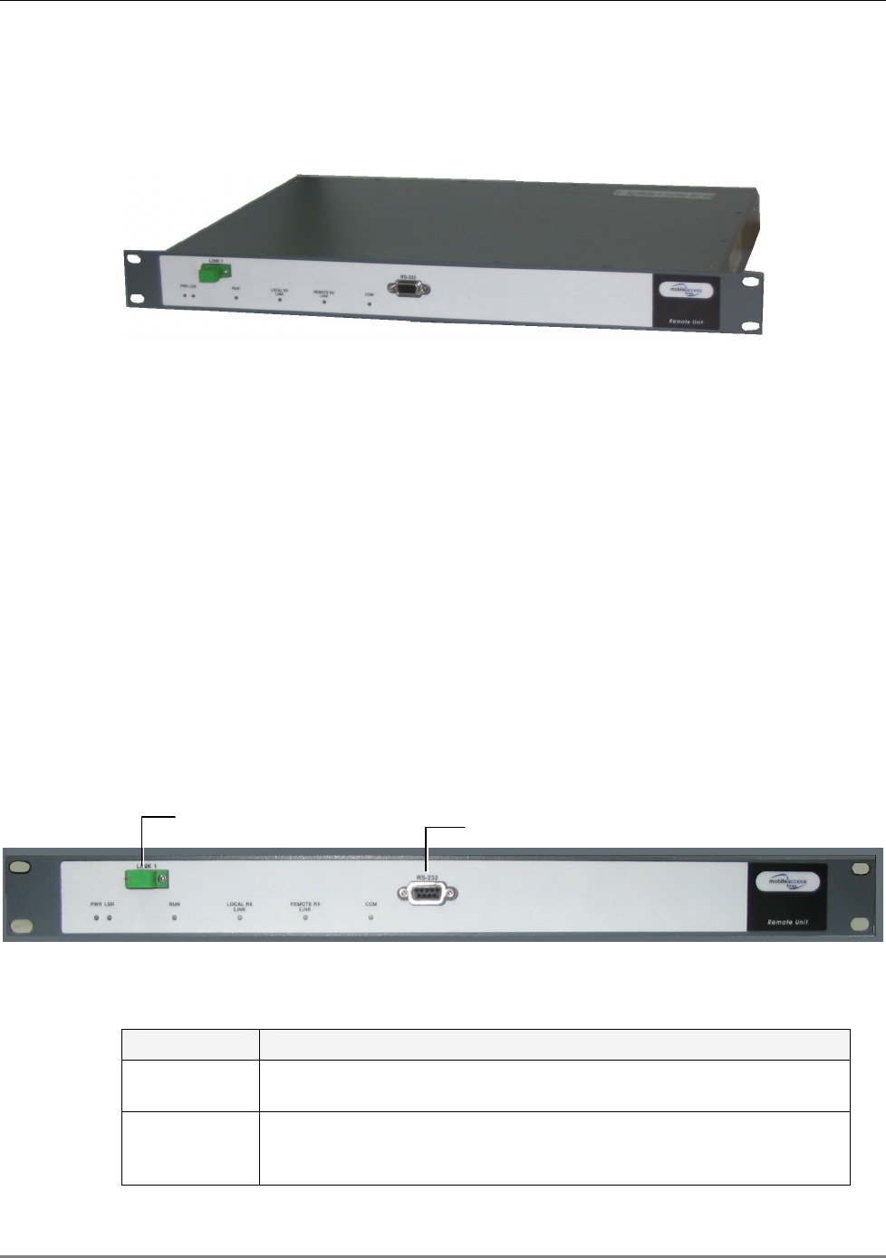
2.1.2 1500 Base Unit Front Panel
The 1500-UHF-BU front panel contains the optical connections, RS232 connection to GUI and the
LED indicators. The following figures show the front panel for both single link and dual link
models of the MA 1500 Main.
The ports are described in Table 2-1 and the indicators in Table 2-2.
Figure 2-2 1500-UHF-BU-1 Front Panel
Figure 2-3. 1500-UHF-BU-2 Front Panel – Two Link Model
Table 2-1. 1500 Main Front Panel Ports
Port Description
Link 1 / Link 2 Fiber Optic connection to MA 1500 Remotes installed at remote sites.
Each link (1/2) corresponds to a remote location.
RS232 com
port
Local RS232 connection to a computer on which the MA 1500 GUI
(setup and monitoring application) has been installed.
F/O connections
Setup and configuration
connection

MA-1500 system Elements
MA 1500 Installation and Configuration Guide 7
Table 2-2. 1500-UHF-BU Front Panel Indicators
LED Description
PWR DC power status:
ON – OK
OFF – no power
LSR Laser condition:
ON – normal (laser locked)
Off – faulty (laser unlocked)
RUN Status of optic adjustment procedure as well as unit processor condition:
Green Blinking – normal. Successful adjustment and processor running.
Orange Blinking - adjustment failed or not performed
Not blinking (Green, Orange, OFF) – unresponsive unit
Local RX link Optic signal received
from
the remote:
Green ON steady – optical signal within range
Blinking – low optical signal
OFF – no optical signal received FROM the REMOTE
Remote RX
link
Optic signal received
at
the remote:
Green ON steady – optical signal within range
Blinking – low optical signal
OFF - no optical signal received AT the REMOTE
COM Status of link communication:
Green – normal communication
Red – faulty communication
OFF – no communication
MA-1500 system Elements
MA 1500 Installation and Configuration Guide 8
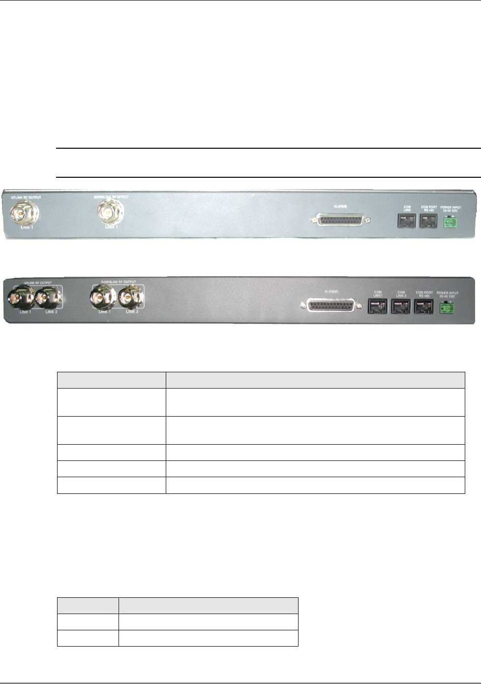
2.1.3 1500-UHF-BU Rear Panel
The 1500-UHF-BU rear panel contains the connections to the BTS interface (RIU or interface
box), to the MA 430 Controller and power connections. The following figures show the rear panel
for the 1500-UHF-BU-1 – single link and 1500-UHF-BU-2 – two link units. A description of the
connections follows.
NOTE: Each COM port supports controller connection to one link: two COM ports are available in
1500-UHF-BU-2 rear panels supporting two links.
Figure 2-4. 1500 Base Unit Rear – Single Link Model
Figure 2-5. 1500 Base Unit Rear –Two Link Model
Table 2-3 1500 Base Unit Rear Panel Connectors
Port Description
Uplink RF Output Uplink RF connections to the BTS passive interface for the
corresponding remote location.
Downlink RF Input Downlink RF connections to the BTS interface passive interface
for the corresponding remote location.
Alarms port Dry contact alarms port connections. See section 2.1.4 for details.
COM LINK(s) Not relevant.
Power Input Power Input 20-48VDC
2.1.4 1500-UHF-BU Dry-Contact Alarms
The Alarms connector on the 1500-UHF-BU-2 rear panel provides two dry-contact connections.
These enable monitoring the optical level of each remote link and reporting to an external alarm
system when the optic link signal is not within range. The connections are
normally closed.
Table 2-4. Alarms Connector
Pin Number
Description
4,5 Link-1: Closed – OK, Open - fault
16, 17 Link-2: Closed – OK, Open - fault
MA-1500 system Elements
MA 1500 Installation and Configuration Guide 9
2.2 1500-UHF-RU Unit Description
The 1500-UHF-RU unit is installed at the remote location and interfaces to the Base Units and
MA 410 controller.
2-6: MA 1500 Remote
2.2.1 Primary Functions
The 1500-UHF-RU unit performs the following main functions:
• Performs optic to RF (and vice versa) service signal conversion at the remote site
• Distributes the RF signals to the antennas
• Provides AGC of the uplink signal from the antenna – adjustable through local
connection from either the Base Unit or Remote units and the MA 1500 GUI
2.2.2 1500-UHF-RU Front Panel
The 1500-UHF-RU front panel contains the optic connection, setup and configuration RS232
connection and LEDs. The following figure show the 1500-UHF-RU front panel. The ports are
described in Table 2-1 and the indicators in Table 2-2.
Figure 2-7 1500-UHF-RU Front Panel
Table 2-5. 1500 Base Unit Front Panel Ports
Port Description
Link Fiber Optic connection to 1500-UHF-BU-2 installed at the Base Unit
site.
RS232 com
port
Setup and configuration connection. Local RS232 connection to a
computer on which the MA 1500 Configuration application has been
installed.
F/O
connections
Setup and configuration
connection

MA-1500 system Elements
MA 1500 Installation and Configuration Guide 10
Table 2-6. 1500 Remote Front Panel Indicators
LED Description
PWR DC power status:
ON – OK
OFF – no power
LSR Laser condition:
ON – normal (laser locked)
Off – faulty (laser unlocked)
RUN Status of optic adjustment procedure as well as unit processor condition:
Green Blinking – normal. Successful adjustment and processor running.
Orange Blinking - adjustment failed or not performed
Not blinking (Green, Orange, OFF) – unresponsive unit
Local RX link Optic signal received from the Base Unit:
Green ON steady – optical signal within range
Blinking – low optical signal
OFF – no optical signal received FROM the BASE UNIT
Remote RX
link
Optic signal received at the remote:
Green ON steady – optical signal within range
Blinking – low optical signal
OFF - no optical signal received AT the BASE UNIT
COM Status of link communication:
Green – normal communication
Red – faulty communication
OFF – no communication
MA-1500 system Elements
MA 1500 Installation and Configuration Guide 11
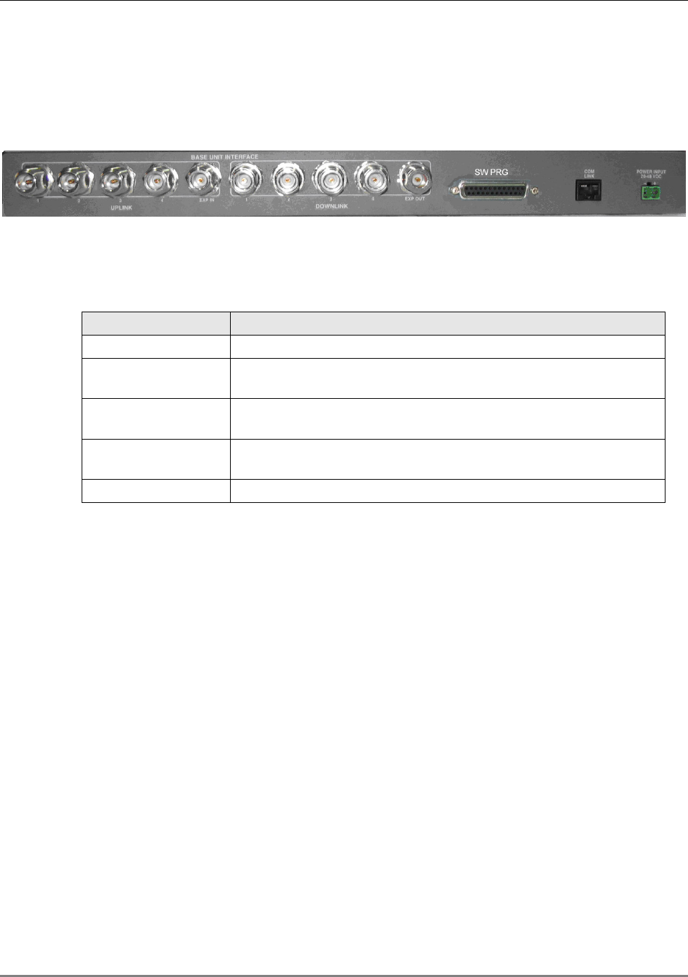
2.2.3 1500-UHF-RU Rear Panel
The 1500-UHF-RU rear panel contains the connections to the power and antennas.
Figure 2-8. 1500-UHF-RU - Rear Panel
Table 2-7. 1500-UHF-RU Rear Panel Connectors
Port Description
Power Power input: 20-48 VDC
SW PRG Software Programming – MA service Personnel use this port (in
addition to the RS232 front panel port) to upgrade the software.
Downlink 1-4 Antenna or duplexer connection, depending on the installation. See
TBD.
Uplink 1-4 Antenna or duplexer connection, depending on the installation. See
TBD.
EXP IN/OUT N/A

Installation
MA 1500 Installation and Configuration Guide 12
3 I
In
ns
st
ta
al
ll
la
at
ti
io
on
n
3.1 Overview
This chapter describes the procedures for mounting the MA 1500 system, and information on
grounding, installation of optical fiber, RF cables and power cables.
NOTE: Be sure to read the Pre-installation and Power Consumption related instructions before
proceeding with the actual connections.
3.2 Pre-installation Instructions
3.2.1 Installation Overview
The MA-1500 system installation consists of the following basic steps:
1. Unpacking and inspecting the MA-1500 system modules and accessory components.
2. Mounting the MA 1500 units in the mounting rack:
• 1500-UHF-BU-2 – in the main building mounting rack
• 1500-UHF-RU – in the remote building mounting rack
3. Connecting the fiber-optic patch cords to the units.
4. Connecting the RF connections to the units
5. Connecting the DC power to the unit
6. Setup and adjustment procedure – Chapter 4
3.2.2 Provided Accessories
The accessories provided with the MA-1500 system kit are listed in the following tables.
Table 3-1: - MA 1500, Accessory Kit for Base Unit - 1 Link
P/N Description Qty
705900003 CABLE RJ45/RJ45 COMUNICATION 1.5 - 2.0 m 2
705900004 CBALE D-TYPE 9P(M)/9P(F) w/ screws-both side 1.8M 1
Table 3-2: - MA 1500, Accessory Kit For Base Unit - 2 Link
P/N Description Qty
705900003 CABLE RJ45/RJ45 COMUNICATION 1.5 - 2.0 m 3
705900004 CABLE D-TYPE 9P(M)/9P(F) w/ screws-both side 1.8M 1

Installation
MA 1500 Installation and Configuration Guide 13
Table 3-3: - MA 1500, Accessory Kit for Remote Unit
P/N Description Qty
705900004 CABLE D-TYPE 9P(M)/9P(F) w/ screws-both side 1.8M 1
3.2.3 Unpacking and Inspection
This section provides instructions for opening the shipping boxes, verifying that all parts have
been received, and verifying that no shipping damage has occurred. The basic MA-1500 system
includes the following items:
• 1500-UHF-BU – one or two-link model depending on the installation
• 1500-UHF-RU – one or two units depending on the 1500-UHF-BU-2 model
Unpack and inspect the cartons according to the following procedure
1. Open the shipping carton and carefully unpack each unit from the protective packing
material.
2. Check for signs of external damage. If there is any damage, call your MobileAccess service
representative.
3.2.4 Rack Installation Instructions
Review the following guidelines to help ensure your safety and protect the equipment from
damage during the installation.
• Only trained and qualified personnel should be allowed to install or replace this
equipment.
• Verify that ambient temperature of the environment does not exceed 50°C (122°F)
• To maintain a low center of gravity, ensure that heavier equipment is installed near the
bottom of the rack and load the rack from the bottom to the top.
• Ensure that adequate airflow and ventilation within the rack and around the installed
components so that the safety of the equipment is not compromised. It is recommended
to allow for at least about 2 cm of airspace between devices in the rack.
• Verify that the equipment is grounded as required – especially the supply connections.

Installation
MA 1500 Installation and Configuration Guide 14
3.2.5 Fiber Optic Rules
• Use single mode fiber
• Use SC/APC connectors (green color) 8 deg only.
• Use minimum splicing/connectors to achieve minimum losses on the fibers.
• Use precaution while installing, bending, or connecting fiber optic cables.
• Use an optical power meter and OTDR for checking the fiber optic cables.
• Make sure the environment is clean while connecting/splicing fiber optic cables.
• All fiber optic connections should be cleaned prior to attaching to termination points
using a dry cleaning device (i.e. Cletop or equivalent).
• Fiber connector protective caps should be installed on all non-terminated fibers and
removed just before they are terminated.
• Check the Fiber Optic connections. You may use the Optical Test Procedure described at
the end of this manual.
• Pay special attention while connecting the SC/APC connectors - you must hear the “click”
when the connection is made.
3.2.6 RF Rules
• Use coax, 50 Ohm, male-to-male N-type for RF connections
• When bending coax cables, verify that the bending radius does not exceed the coax
specifications.
• Use a VSWR meter (i.e. Site Master or equivalent) for checking coax cables

Installation
MA 1500 Installation and Configuration Guide 15
3.3 Power Consumption, Connections and Power
Supplies
3.3.1 Power Safety Instructions
SAFETY WARNINGS
When installing or selecting the power supplies:
• Be sure to disconnect all power sources before servicing.
• Calculate the required power according to the requirements of the specific installation
and then determine the configuration of the power supplies. The required DC cables will
then be determined by the selected PS configuration.
• Use only UL approved power supplies
• Install external over-current protective devices for the system according to the
requirements described in section 3.3.3.
3.3.2 Power Requirements
Table 3-4. MobileAccess™ Power Requirements
Unit Type Voltage Input
Typical Power
Consumption
Maximum Current
Consumption
MA 1500 BU 20-48VDC 20 W max 1 A
MA 1500 RU
20-48VDC 20 W max 1 A
3.3.3 Circuit Breakers
NOTE: Circuit breakers are relevant only in installations where power is supplied from remote
sources.
3.4 Installation Procedure
This section provides examples of some basic MA-1500 system installations. The examples can
be used as a basis for understanding how to connect any other installation configurations.
Each example includes an overview diagram, followed by illustration of the physical connections
and step-by-step instructions.
Installation
MA 1500 Installation and Configuration Guide 16
3.4.1 Example 1: Stand Alone
Figure 3-1 shows the connections in a stand alone topology with two types of antenna
connections:
• Simplex antennas - where one antenna transmits the signals and the other receives the
signals.
• Duplex antenna – where a single antenna transmits and receives the signals in both
directions. The signals are routed through SM F/O connections to the remote locations.
Figure 3-1: Two Link Base Unit with a Slave Controller at each Remote Site
Installation
MA 1500 Installation and Configuration Guide 17
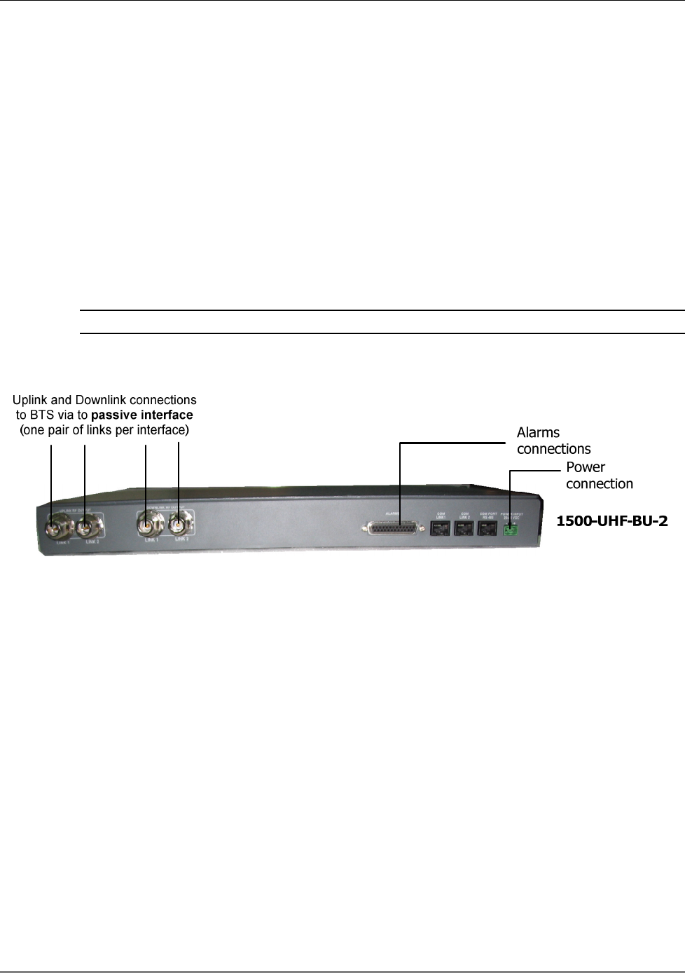
3.4.1.1 1500-UHF-BU-2 Connections
1. Connections to passive-interface box - using N-Type cables connect the uplink and
downlink ports on the 1500-UHF-BU rear panel to the passive interface box.
2. Alarms connections - (optional) connect to an external monitoring system according to
section 2.1.4.
3. Power – connect to the DC power according to section 1.2.6
The following figure shows the physical connections to the MA 1500 Base Unit. The figures are
followed by instructions.
NOTE: Only the connections relevant the MA 1500-UHF units are shown.
Figure 3-2: 1500-UHF-BU-2 Building Connections
Installation
MA 1500 Installation and Configuration Guide 18
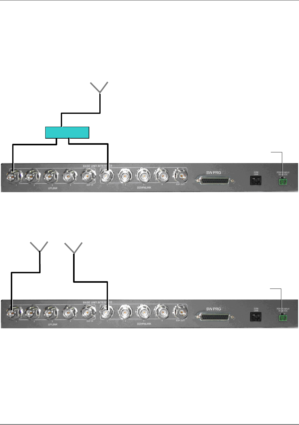
3.4.1.2 1500-UHF-RU Connections
The following two figures show the 1500-UHF-BU connections to duplex antennas (via duplexer)
and to simplex antennas (direct). Duplexer must supply 50 dB of isolation between the DL and
UL bands.
DUPLEXER
DUPLEX ANENNA
SIMPLEX
ANTENNA Tx SIMPLEX
ANTENNA Rx
Connection
to DC
Connection
to DC

Setup and Adjustment Procedure
MA 1500 Installation and Configuration Guide 19
4 S
Se
et
tu
up
p
a
an
nd
d
A
Ad
dj
ju
us
st
tm
me
en
nt
t
P
Pr
ro
oc
ce
ed
du
ur
re
e
4.1 Overview
The MA 1500 Setup and Adjustment Tool is an intuitive GUI based software application that
enables end-to-end configuration and monitoring of the MA-1500 system through a local
connection to either the 1500-UHF-BU-2 or 1500-UHF-RU unit of the same link.
NOTE: The MA-1500 GUI is the same GUI tool as for the MA-330. The application (MA 330 GUI)
is supplied on a CD with your installation kit.
The MA 1500 GUI is used to:
• Configure the BTS interface type (required setup procedure)
• Perform the optical adjustment procedure (required setup procedure)
• Configure AGC for the MA 1500 Remote
• View H/W, S/W versions
NOTE: Access to the various configuration and setup options is limited by password protected
user levels.
4.2 Software Installation
To install the application
There are four directories on your Installation CDs. In the Customer GUI directory, double-click
MA 330_x_x_x.exe and follow the installation instructions.
4.3 How to Use the MA 1500 Setup Tool
The MA 330 GUI application is required for completing the installation procedure and for
monitoring the MA-1500 system elements.
The following list clarifies the procedures for using the application:
1. Install the MA 330 GUI supplied with the installation CD on a computer (preferably a laptop)
with which you can locally connect to the MA-1500 system (either Base Unit on Remote
units).
Setup and Adjustment Procedure
MA 1500 Installation and Configuration Guide 20
2. Connect the computer to the MA-1500 system (either Base or remote unit) and launch the
application.
3. Login under the User Name Field Eng and the Password Eng (the password can then be
changed for security reasons).
NOTE: The next steps are all performed from the MA 1500 Setup application.
4. Review the MA 330 Tool windows according to section 4.5
5. Setup and adjust the MA-1500 system according to section 4.6.
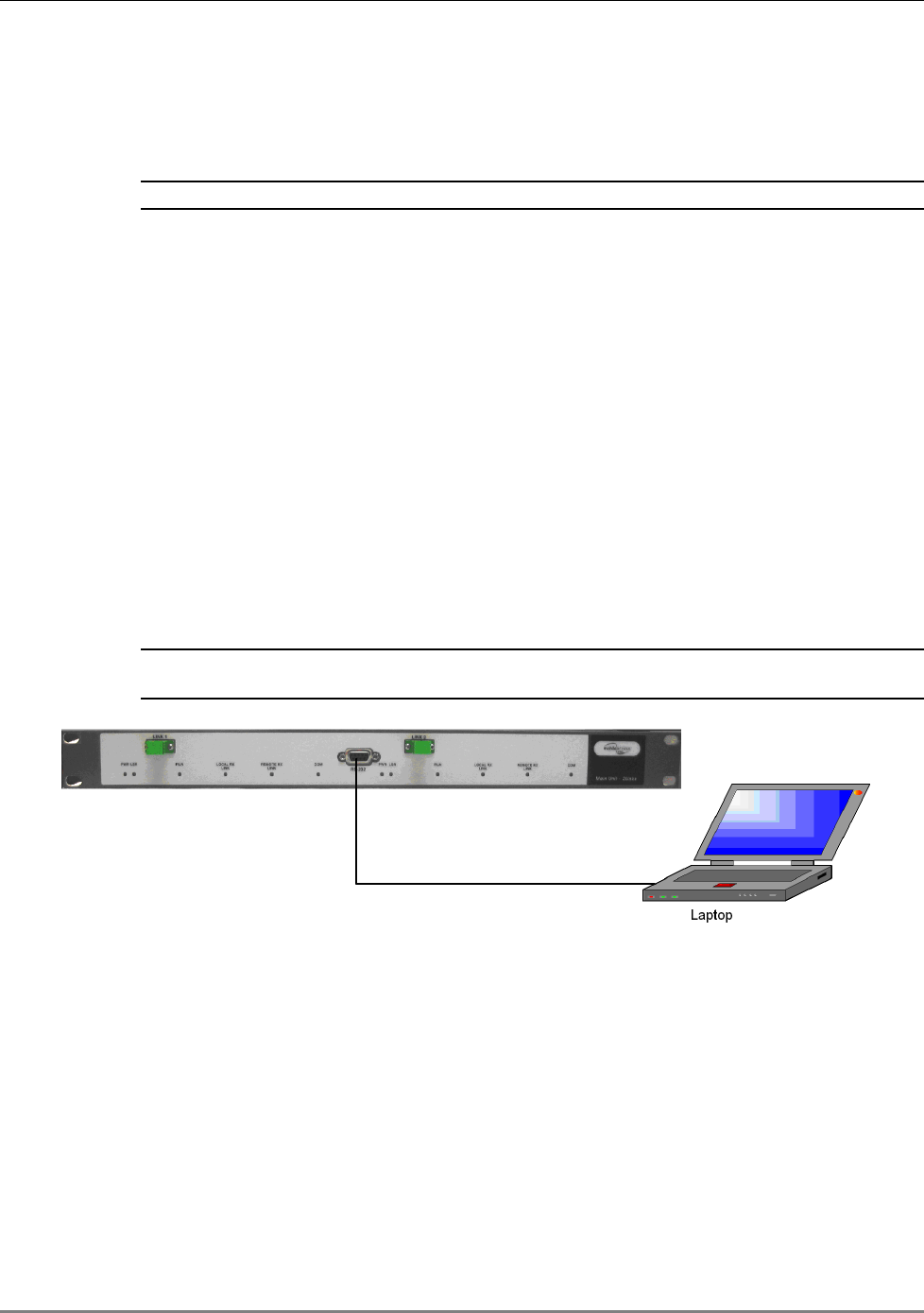
4.4 Installing and Launching the Application
4.4.1 Installation and Connection
1. Using the supplied Installation CD, install the MA 330 GUI on the computer (usually laptop)
from which the adjustment procedure will be performed.
2. Connect a standard RS232 cable between the RS232 port you computer and the RS232 port
on either the 1500-UHF-BU or 1500-UHF-RU.
NOTE: 1500-UHF-BU-2 has only one RS232 port. You will be required to choose the link on which the
current adjustment is performed through the Main window.
Figure 4-1. MA 1500 GUI Tool Connection
Setup and Adjustment Procedure
MA 1500 Installation and Configuration Guide 21
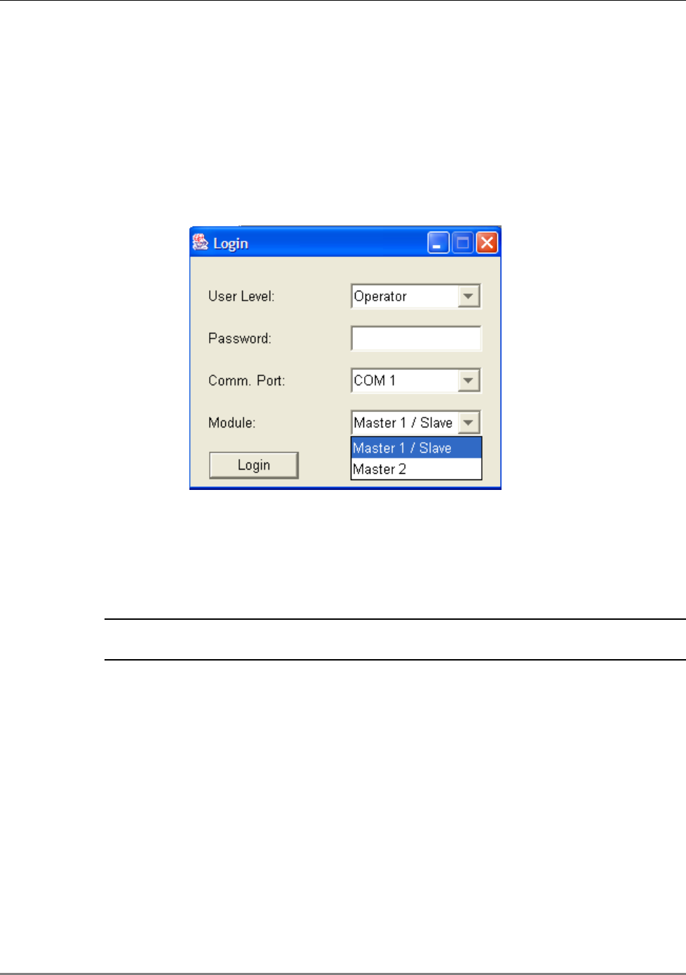
4.4.2 Launching the Application and Logging In
1. To launch the application, perform one of the following:
• Double-click on the MA 330 icon on your desktop, or
• From the Windows Start menu, choose Program and click MA 330 GUI
The following login window appears.
Figure 4-2. Login Dialog
2. To login at a User Level that enables configuring the system:
• In the User Level field, select Field Eng.
• Enter the default Engineering password eng.
NOTE: It is recommended to change the default passwords. For more information on the User Levels,
Passwords and Password change, refer to section
4.10).
3. Select the Comm Port according to the currently active COMM port on your computer.
4. In the Module field, select the link to be adjusted:
• To connect to the first link on the 1500-UHF-BU-2 unit, choose Master 1 / Slave
• To connect to the second link on the 1500-UHF-BU-2 unit, choose Master 2
• To connect to the 1500-UHF-RU unit, choose Master 1 / Slave
5. Click Login. The main window appears. The window is described in the following section.
Setup and Adjustment Procedure
MA 1500 Installation and Configuration Guide 22
4.5 Navigating MA 1500 GUI
Upon login, the 1500-UHF-BU-2 window appears, displaying the Operator tab by default and the
parameters for the currently selected link. The windows contains two configuration and
monitoring tabs at different levels: Operator and Advanced.
Both tabs are divided into two window areas: Main and Remote. This enables you to define
and monitor the parameters of either device on the link (1500-UHF-BU-2 or MA 1500 Remote).
A third tab – Block Diagram contains a block diagram showing the UL and DL signal paths and
the exact points that some of the measurements were made.
Additional buttons provide administrator functions as follows:
• Security - enables the user to modify the default password given for each authorization
level (see section 4.10).
• Connect/Disconnect – used to change links at the MA 1500 unit (between Link 1 and
Link 2)
• Close – application exit function
Figure 4-3. Main Window
Setup and Adjustment Procedure
MA 1500 Installation and Configuration Guide 23
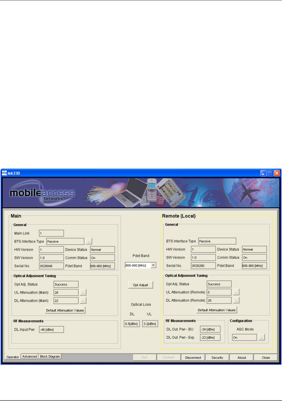
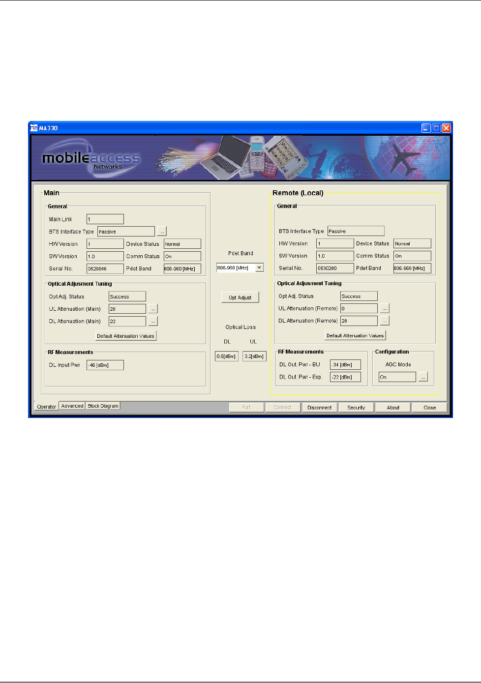
4.5.1.1 Operator Tab
The Operator tab provides the optical adjustment and basic monitoring functions. It also shows
the versions of each of the units on the link.
Figure 4-4: Operator Tab
Setup and Adjustment Procedure
MA 1500 Installation and Configuration Guide 24
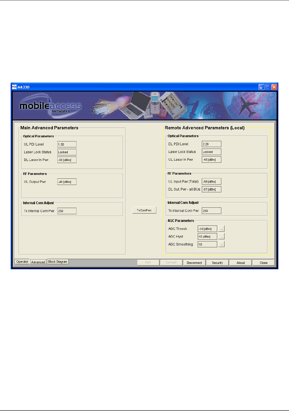
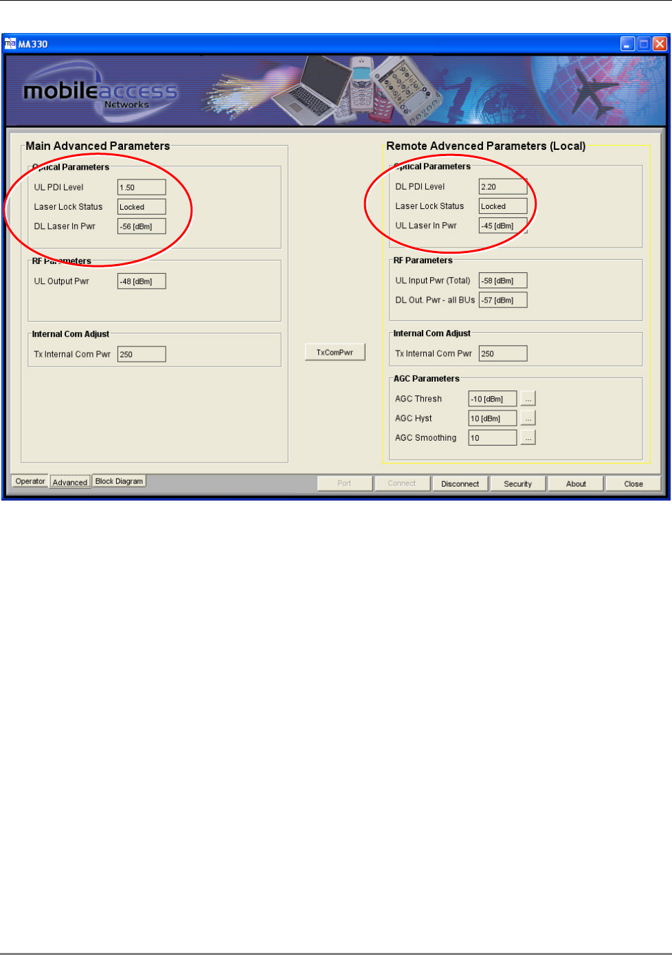
4.5.1.2 Advanced Tab
The Advanced tab contains advanced monitoring parameters, AGC control parameters and
advanced adjustment parameters used for further optimizing the adjustment procedure.
Like the Operator’s tab, the Advanced tab is divided into two areas: Main and Remote. This
enables configuring and monitoring the main and remote units on the link at the same time.
Figure 4-5: Advanced Dialog
Setup and Adjustment Procedure
MA 1500 Installation and Configuration Guide 25
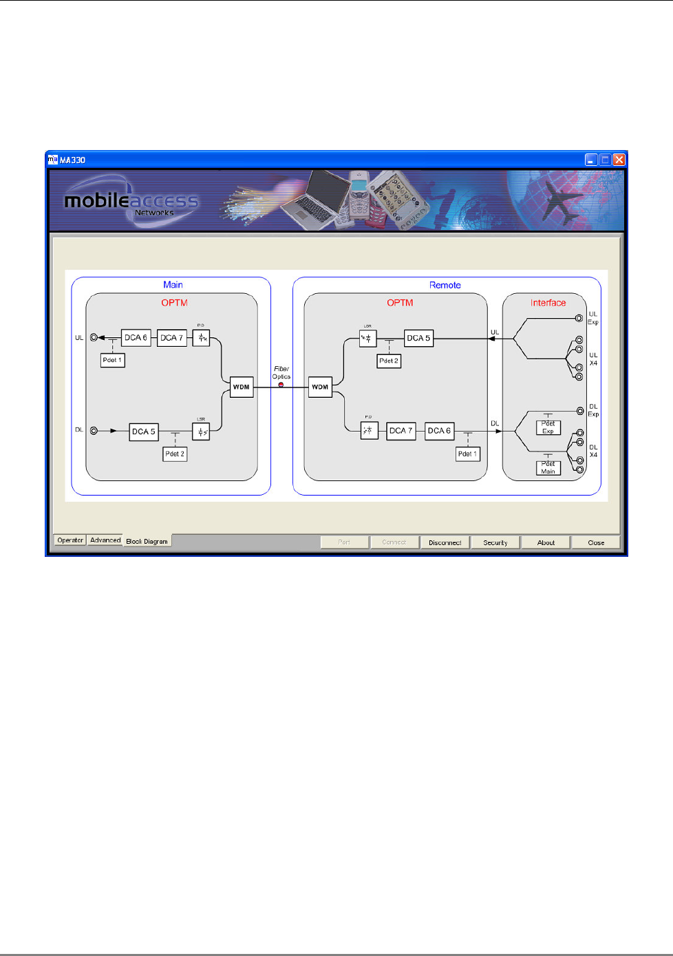
4.5.1.3 Block Diagram
This diagram shows the measurement points and DCA (Digital Control Attenuation) in the UL
and DL path.
Figure 4-6: Block Diagram
4.6 Commissioning
The commissioning procedure consists of the following procedures:
1. Verify that the BTS interface type is defined as Passive ( 4.6.1).
2. Perform the optical adjustment procedure ( 4.6.2).
3. Optional – setting AGC to ON.
The 1500-UHF-RU AGC is set to OFF by default. You may change the setting to ON ( 4.7.1).
4. Monitor the system to verify that the RF parameters are at the required level and that there
are no errors ( 4.8).
Setup and Adjustment Procedure
MA 1500 Installation and Configuration Guide 26
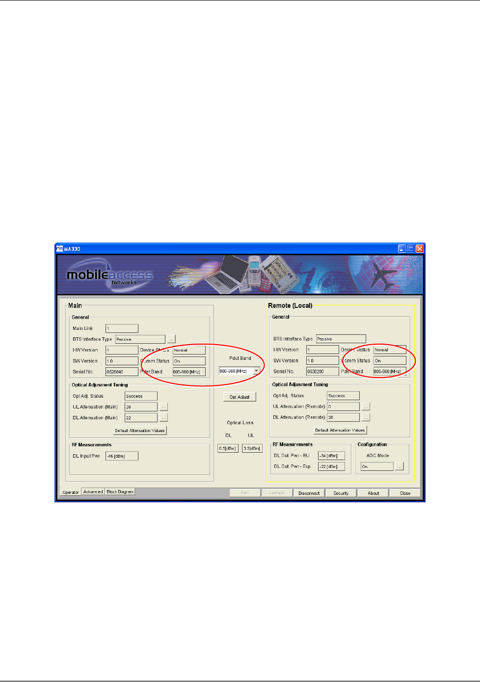
4.6.1 Verifying the BTS Interface Configuration
1. Access the MA 1500 GUI main window, Operator tab. The current link is automatically
displayed.
2. Under General, verify that the BTS Interface is set to Passive. Otherwise click the
Browse (…) button and choose Passive Interface.
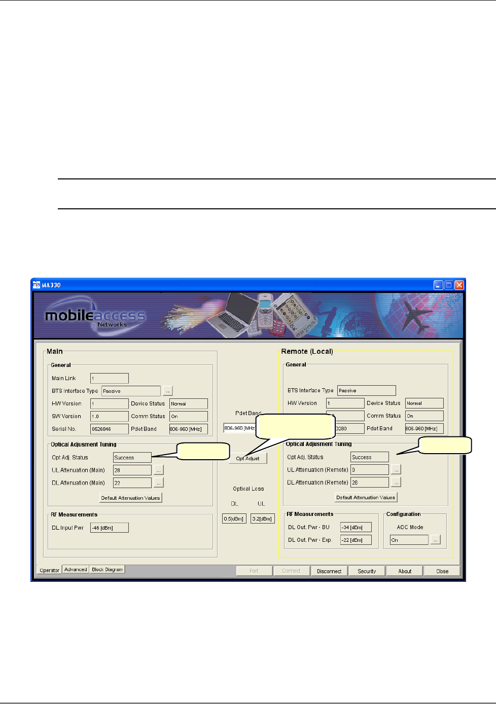
4.6.2 Optical Adjustment
This procedure compensates for the loss over the optic fiber and the MA 1500 units.
NOTE: If there is no optical loss, the total gain (before the optical adjustment procedure) is
factory set to 0 dB.
To perform the Optical Adjustment Procedure
1. Verify that the correct link Main Link (if relevant) is selected and that the BTS Interface
type has been selected.
Figure 4-7: Optical Adjustment Parameters
2. In the Operator dialog click on Optical Adjust.
3. In the Optical Adjust Tuning areas of both Main and Remote, verify that the Optical
Adjust Status is Successful.
Optical Adjustment
button
Successful
Successful
Setup and Adjustment Procedure
MA 1500 Installation and Configuration Guide 27
4. The adjustment procedure compensations are made for variations in F/O loss of up to
9 optical dB or 18 dB and the following inputs:
• Passive (BTS) Interface input: 0 dBm
• RIU (BTS) Interface input: -20 dBm
NOTES:
1. The Optical Loss parameter shows the optical loss over the F/O cable and connectors,
calculated during the optical adjustment procedure.
2. To reset the optical adjustment according to the default input values and 0 dB gain, click the
Default Attenuation Values button in the Main and the Remote window area.
4.7 AGC Setting
By default, MA 1500 operates with AGC OFF. You may set the system to run with AGC ON and in
addition modify the AGC parameters.
NOTE: Only experienced users should modify the AGC parameters.
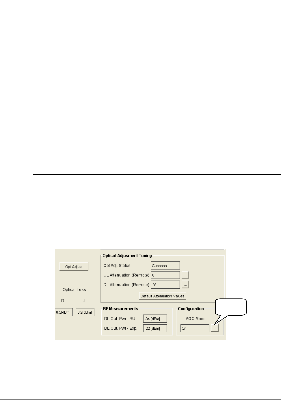
4.7.1 Enabling/Disabling AGC
To enable/disable AGC
1. Login at Field Eng user level and access the Operator tab.
2. Under RF Measurements, Configuration, click on the AGC Mode browse (…) button and
set AGC to ON.
Figure 4-8: Enabling/Disabling AGC
Click to set
AGC ON/OFF
Setup and Adjustment Procedure
MA 1500 Installation and Configuration Guide 28
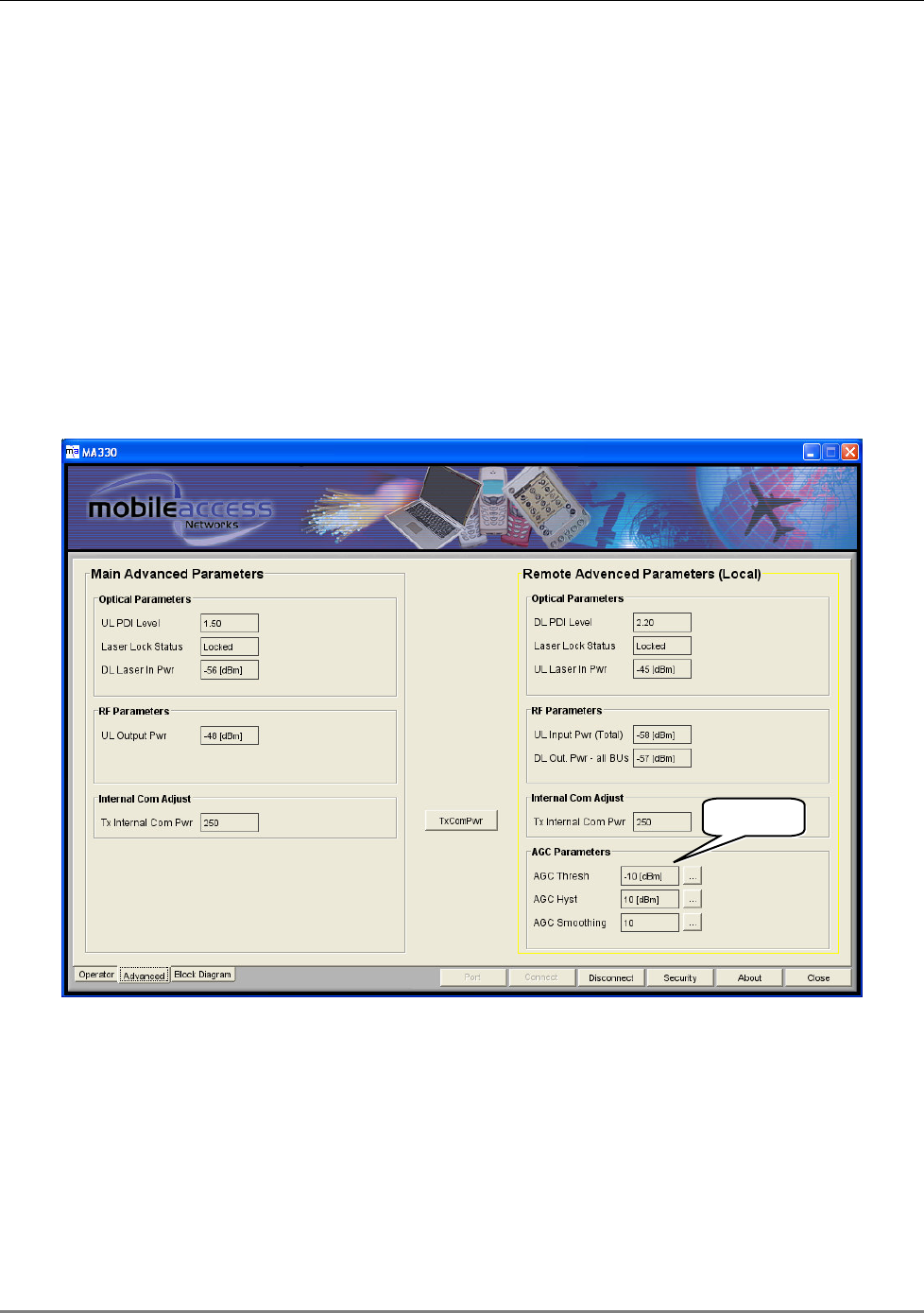
4.7.2 Changing AGC Settings
To change the AGC Settings
1. Login at Field Eng user level and access the Advanced tab.
2. Under Remote Advanced Parameters, AGC Parameters, you may modify the following
AGC parameters by clicking the corresponding Browse (…) button and choosing the new
values:
• AGC threshold – adjusted to prevent AGC action on noise peaks
• AGC Hysteresis - Prevents minor excursions around a set point
• AGC Smoothing - Smoothing over a moving time window
Figure 4-9: Enabling/Disabling AGC
AGC Settings
Setup and Adjustment Procedure
MA 1500 Installation and Configuration Guide 29
4.8 Monitoring
The MA 1500 GUI enables you to monitor system status as well as the RF and Optical signal
levels at significant points in the uplink and downlink. These can be used for verifying the link
status and for fault sourcing.
The monitored points are clearly shown in the diagram accessible by clicking the Block
Diagram tab. The parameters are located in both the Operator and the Advanced tabs.
4.8.1 Monitoring System Status
After commissioning the MA 1500 system, the MA 1500 setup application may be used to
monitor the link RF signal values
Table 4-1. MA 1500 Status Parameters
Setup and Adjustment Procedure
MA 1500 Installation and Configuration Guide 30
Parameter Description
Device Status Unit operational status and error indication:
Normal - no errors detected
Minor – minor error detected
Major – major error detected
Opt. Adj. Status Status of optical adjustment procedure:
Success – procedure performed successfully
Fail – adjustment procedure failed
Default – adjustment procedure not performed
COMM Status Corresponds to COM LED on the front panel. Status of
communication between Remote and Main measured according to
the (MER) Message Error Rate :
OFF – No communication detected.
ON - Communication OK.
Partial – Communication fault
Pdet Band Shows the band at which the RF power readings (power
detection) are performed.
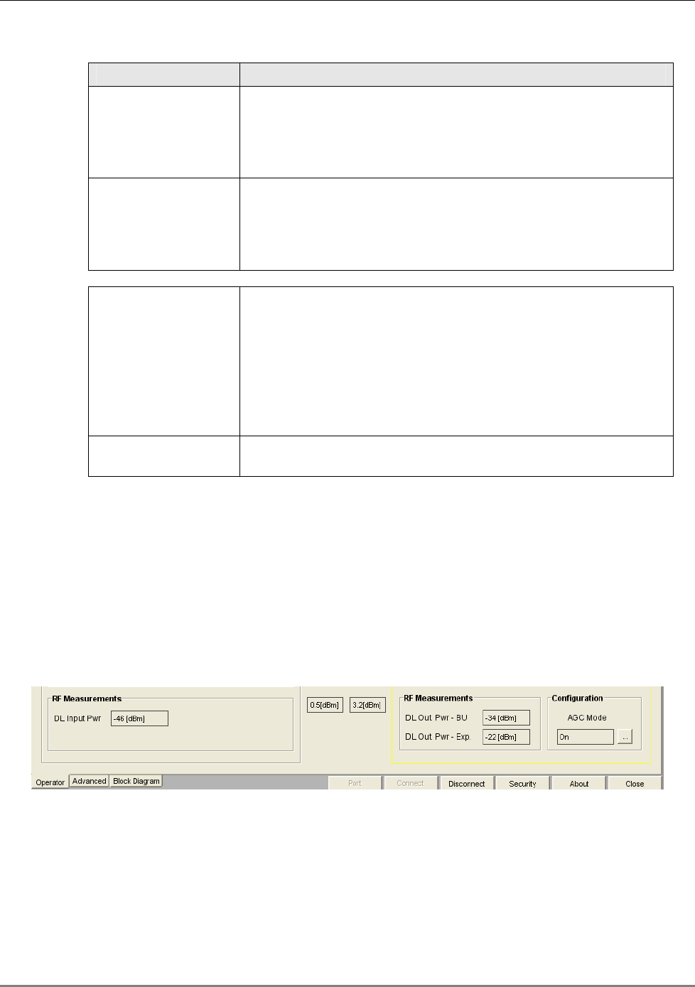
4.8.2 Monitoring the RF Parameters
You can monitor the approximate level of the following RF parameters in the Operator’s tab:
• DL Input PWR – approximate power input from the BTS interface source
• DL Out PWR – BU – approximate output power to individual Base Units
• DL Out PWR – Exp – approximate output power to the Expansion Box
Figure 4-10: RF Parameters in the Operator tab
The following RF parameters are available in the Advanced tab:
• DL Out PWR – all BUs – approximate power entering all BUs before it is distributed
between the BUs
• UL Input PWR – the approximate power input from the BU interface source
Setup and Adjustment Procedure
MA 1500 Installation and Configuration Guide 31
• UL Out PWR – BU – approximate output power towards the BTS interface
Figure 4-11: RF Parameters in the Advanced tab
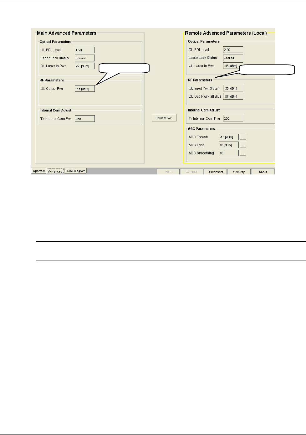
4.8.3 Monitoring the Optical Parameters
Parameters indicating the condition of the optical elements are located in the Advanced tab as
shown below.
NOTE: The optical adjustment related parameters are located in the Operator’s tab and are
described in section
4.5.1.1 – Commissioning.
The following optical parameters are available in the Advanced tab:
• UL PDI level (Remote/Main) – indicates whether optical level is within range (Normal),
High, or Low.
• Laser lock status – indicates status of laser: Locked = Normal, Unlocked = Fault
• DL/UL Laser in PWR – indicates whether level of optical signal is within range
Main RF parameter
Remote RF parameter
Setup and Adjustment Procedure
MA 1500 Installation and Configuration Guide 32
Figure 4-12: RF Parameters in the Advanced tab
4.9 Viewing Versions
You may need to identify information such as serial number, or versions of the installed units for
upgrade purposes or for reporting to the MobileAccess representative. These are displayed in the
Operator tab under the Main and Remote window areas.
4.10 Security Management
4.10.1 Authorization Levels and Passwords
Access is enabled at three authorization levels. Each level is provided with a default password
that can be changed through the Security menu.
Authorization Levels
Setup and Adjustment Procedure
MA 1500 Installation and Configuration Guide 33
• Oper – enables the user to view the configuration and the events display. Events
acknowledge capabilities are not available to Operator level users.
Default password = ‘oper’
• Field Eng – provides configuration capabilities to all options displayed at this entry
level.
Default password = ‘eng’
• Technical Support – restricted to MA service personnel.
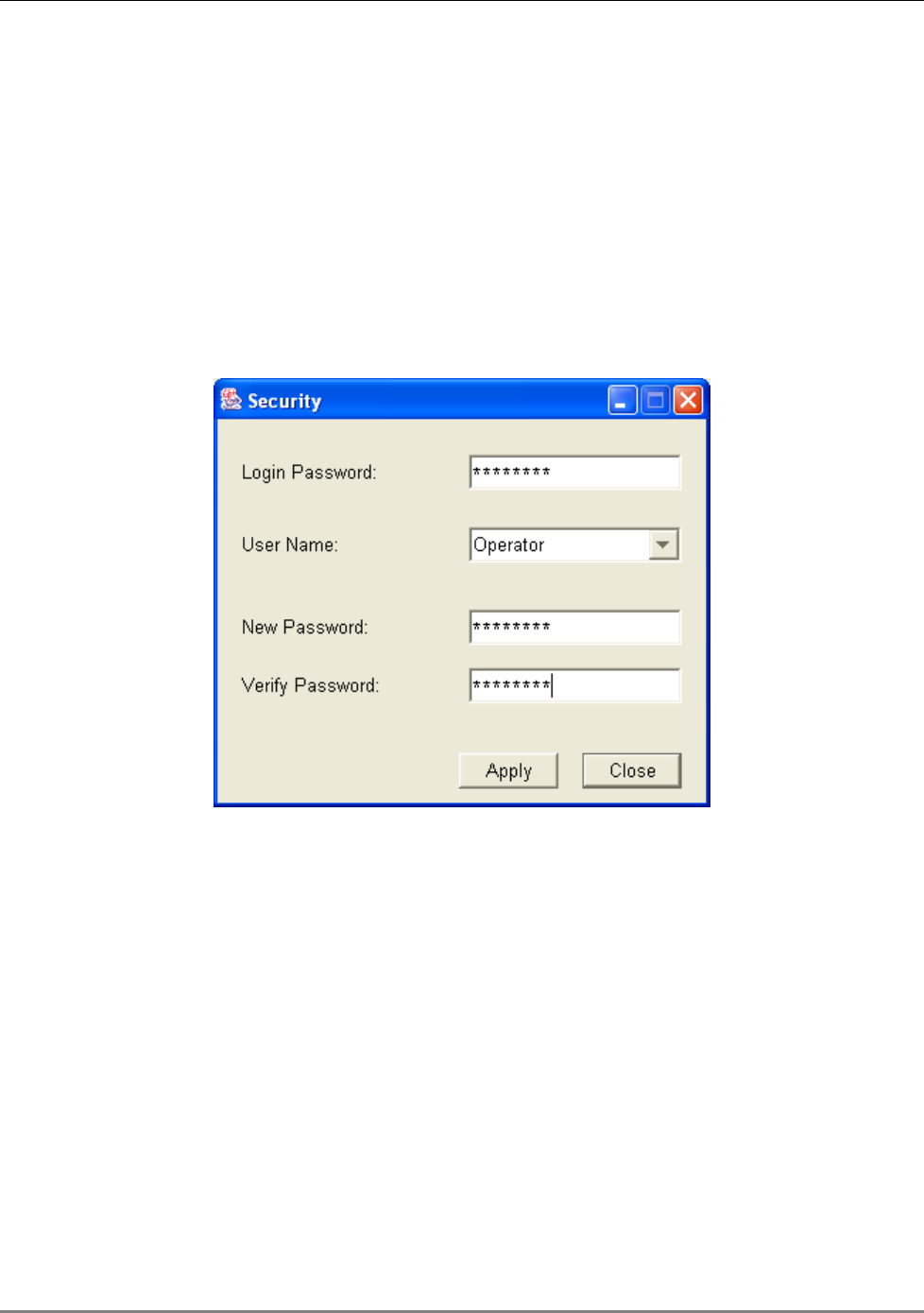
To modify the password
Click on the Security tab on the bottom menu in the Operator window. The following dialog
appears.
1. In the Login Password, enter the current password.
2. Select the User Name whose password is to be modified.
3.
In New Password type the new password. Type the password again in Verify Password.
4.
Click Apply.