Corning Optical Communication MA1K-IDEN-SMR RF Booster User Manual MobileAccess 2000
Corning Optical Communication Wireless RF Booster MobileAccess 2000
Contents
- 1. Users Manual Part 1
- 2. Users Manual Part 2
- 3. Users Manual Part 3
Users Manual Part 1

Installation and Configuration Guide
709C001901
UM-1000 Ver. 2.10
MAY 2006
MA Nextel 1000 System

MA 1000 Installation and Configuration Guide
II
MobileAccess Nextel 1000
Copyright © 2006 MobileAccess.
© 2005 by MobileAccess
This document contains confidential and proprietary information of MobileAccess and may not
be copied, transmitted, stored in a retrieval system or reproduced in any format or media, in
whole or in part, without the prior written consent of MobileAccess. Information contained in
this document supersedes any previous manuals, guides, specifications, data sheets or other
information that may have been provided or made available to the user. This document is
provided for informational purposes only, and MobileAccess does not warrant or guarantee
the accuracy, adequacy, quality, validity, completeness or suitability for any purpose of the
information contained in this document. MobileAccess reserves the right to make updates,
improvements and enhancements to this document and the products to which it relates at
any time without prior notice to the user. MOBILEACCESS MAKES NO WARRANTIES,
EXPRESS OR IMPLIED, INCLUDING, WITHOUT LIMITATION, THOSE OF MERCHANTABILITY
AND FITNESS FOR A PARTICULAR PURPOSE, WITH RESPECT TO THIS DOCUMENT OR ANY
INFORMATION CONTAINED HEREIN.
Trademark acknowledgement
MobileAccessTM is a registered trademark of MobileAccess. This document contains other
trademarks, trade names and service marks of MobileAccess and other organizations, all of
which are the property of their respective owners.
MobileAccess Ltd. Vienna, Virginia Tel: +1-703-848-0200
MobileAccess Ltd. Lod, Israel Tel: +972-8-9183888
0Hhttp://www.MobileAccess.com
Email: sales@MobileAccess.com

MA 1000 Installation and Configuration Guide
III
Policy For Warrantee And Repair
MobileAccess tests and inspects all its products to verify their quality and reliability.
MobileAccess uses every reasonable precaution to ensure that each unit meets their declared
specifications before shipment. Customers should advise their incoming inspection, assembly,
and test personnel about the precautions required in handling and testing our products. Many
of these precautions can be found in this manual.
The products are covered by the following warranties:
General Warranty
MobileAccess warrants to the original purchaser all standard products sold by MobileAccess to
be free of defects in material and workmanship for one (1) year from date of shipment from
MobileAccess. During the warranty period, MobileAccess will repair or replace any product
that MobileAccess proves to be defective. This warranty does not apply to any product that
has been subject to alteration, abuse, improper installation or application, accident, electrical
or environmental over-stress, negligence in use, storage, transportation or handling.
Specific Product Warranty Instructions
All MobileAccess products are warranted against defects in workmanship, materials and
construction, and to no further extent. Any claim for repair or replacement of units found to
be defective on incoming inspection by a customer must be made within 30 days of receipt of
shipment, or within 30 days of discovery of a defect within the warranty period.
This warranty is the only warranty made by MobileAccess and is in lieu of all other
warranties, expressed or implied. MobileAccess sales agents or representatives are not
authorized to make commitments on warranty returns.
Returns
In the event that it is necessary to return any product against above warranty, the following
procedure shall be followed:
1. Return authorization is to be received from MobileAccess prior to
returning any unit. Advise MobileAccess of the model, serial number,
and discrepancy. The unit may then be forwarded to MobileAccess,
transportation prepaid. Devices returned collect or without authorization
may not be accepted.
2. Prior to repair, MobileAccess will advise the customer of our test results
and any charges for repairing customer-caused problems or out-of-
warranty conditions etc.
3. Repaired products are warranted for the balance of the original warranty
period, or at least 90 days from date of shipment.

MA 1000 Installation and Configuration Guide
IV
Limitations Of Liabilities
MobileAccess's liability on any claim, of any kind, including negligence for any loss or damage
arising from, connected with, or resulting from the purchase order, contract, quotation, or
from the performance or breach thereof, or from the design, manufacture, sale, delivery,
installation, inspection, operation or use of any equipment covered by or furnished under this
contact, shall in no case exceed the purchase price of the device which gives rise to the
claim.
EXCEPT AS EXPRESSLY PROVIDED HEREIN, MOBILEACCESS MAKES NO WARRANTY, EXPRESSED OR IMPLIED,
WITH RESPECT TO ANY GOODS, PARTS AND SERVICES PROVIDED IN CONNECTION WITH THIS AGREEMENT
INCLUDING, BUT NOT LIMITED TO, THE IMPLIED WARRANTIES OF MERCHANTABILITY AND FITNESS FOR A
PARTICULAR PURPOSE. MOBILEACCESS SHALL NOT BE LIABLE FOR ANY OTHER DAMAGE INCLUDING, BUT NOT
LIMITED TO, INDIRECT, SPECIAL OR CONSEQUENTIAL DAMAGES ARISING OUT OF OR IN CONNECTION WITH
FURNISHING OF GOODS, PARTS AND SERVICE HEREUNDER, OR THE PERFORMANCE, USE OF, OR INABILITY TO
USE THE GOODS, PARTS AND SERVICE.
Reporting Defects
The units were inspected before shipment and found to be free of mechanical and electrical
defects.
Examine the units for any damage that may have been caused in transit. If damage is
discovered, file a claim with the freight carrier immediately. Notify MobileAccess as soon as
possible.
NOTE: Keep all packing material until you have completed the inspection
WARNING: To comply with FCC RF exposure compliance requirements, antennas used for
this product must be fixed mounted on indoor permanent structures, providing a separation
distance of at least 20 cm from all persons during normal operation.
WARNING: Antenna gain should not exceed 10dBi.
WARNING: Each individual antenna used for this transmitter must be installed to provide a
minimum separation distance of 20 cm or more from all persons and must not be co-located
with any other antenna for meeting RF exposure requirements.
WARNING: The design of the antenna installation needs to be implemented in such a way
so as to ensure RF radiation safety levels and non- environmental pollution during operation.
ATTENTION:
Compliance with RF safety requirements:
• MobileAccess™ products have no inherent significant RF radiation.
• The RF level on the down link is very low at the Remote Units (RHUs) downlink ports.
Therefore, there is no dangerous RF radiation when the antenna is not connected.
MA 1000 Installation and Configuration Guide
V
Laser Safety
LASER WARNING
Fiber optic ports of the MobileAccess 1000/2000 emit invisible laser radiation at the 1310 nm wavelength
window.
To avoid eye injury never look directly into the optical ports, patchcords or optical cables. Do not stare
into beam or view directly with optical instruments. Always assume that optical outputs are on.
Only technicians familiar with fiber optic safety practices and procedures should perform optical fiber
connections and disconnections of the MobileAccess 1000/2000 modules and the associated cables.
The MobileAccess 1000/2000 complies with 21 CFR 1040.10 and 1040.11 except for deviations pursuant
to Laser Notice NO. 50 (July 26, 2001) & IEC 60825-1, Amendment 2 (Jan. 2001).
Care of Fiber Optic Connectors
F/O Connectors Cautions
Do not remove the protective covers on the fiber optic connectors until a connection is ready to be made.
Do not leave connectors uncovered when not connected.
The tip of the fiber optic connector should not come into contact with any object or dust.
Refer to the cleaning procedure for information on the cleaning of the fiber tip.
Certification
MobileAccess products have met the approvals of the following certifying organizations:
ISO 9001
For US: FCC 47 CFT part 22,24,90
FDA-CDRH
For Canada: RSS-118, RSS-119, RSS-133….

MA 1000 Installation and Configuration Guide
VI
NOTE: This equipment has been tested and found to comply with the limits for a Class A digital device,
pursuant to Part 15 of the FCC Rules. These limits are designed to provide reasonable protection against
harmful interference when the equipment is operated in a commercial environment. This equipment
generates, uses, and can radiate radio frequency energy and, if not installed and used in accordance with
the instruction manual, may cause harmful interference to radio communications. Operation of this
equipment in a residential area is likely to cause harmful interference in which case the user will be
required to correct the interference at his own expense.
Warning!
Changes or modifications to this equipment not expressly approved by Mobile Access Ltd. could void the
user’s authority to operate the equipment.

MA 1000 Installation and Configuration Guide
VII
Preface
This user guide provides all the information necessary to install and configure the
MobileAccess Nextel 1000 System.
Revision History
The revision history for this document is shown in Table 1-1.
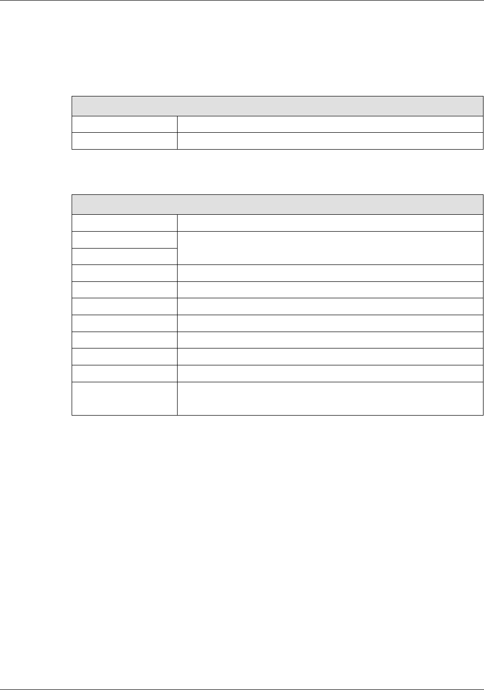
Table 1-1: Revision history
Version Date Description
1.0 April 2003 Initial version.
2.0 October 2003 Updated version to MobileAccess.
2.1 November 2003 Review and editing
2.2 December 2003 Adding and updating RHU 1200
2.3 September 2004 Update for Nextel Specific Installs
2.4 September 27 Review Nextel’s inputs
2.6 05-FEB-05 Safety and power requirements
2.7 10-FEB-05 RHU 800/900 with no filter jumper illustration
2.8 10-MARCH-05 Updating RHU 800/900 Filter Connections
2.9 MARCH-05 Section 5.1 - Nextel Items Master No.
2.10 MAY-06 Section 3.3.4 Coaxial cable Lengths and Losses

MA 1000 Installation and Configuration Guide
VIII
Table of Contents
1 Introduction.......................................................................................................................... 1
1.1 About MobileAccess™ 1000........................................................................................................ 1
1.1.1 Features.......................................................................................................................... 1
1.2 System Architecture .................................................................................................................. 2
1.3 Configuration Options................................................................................................................ 4
1.4 MA 410/430 Remote Management ..............................................................................................5
1.5 MobileAccess Models ................................................................................................................. 7
1.5.1 Nextel Item Master Numbers for MobileAccess-1000 iDEN ................................................... 9
2 System Elements.................................................................................................................10
2.1 Remote Modules ..................................................................................................................... 10
2.1.1 MA 1000 RHUs .............................................................................................................. 10
2.1.1.1 RHU 1000 Front Panel ........................................................................................ 11
2.1.1.2 RHU 1000 Rear Panel ......................................................................................... 12
2.1.2 RHU 800/900................................................................................................................. 13
2.1.2.1 RHU 800/900 Front Panel ................................................................................... 14
2.1.2.2 RHU 800/900 Rear Panel .................................................................................... 14
2.1.2.3 RHU 800/900 View of Filter Connection................................................................ 15
2.1.3 MA 1200 Add-on............................................................................................................ 16
2.1.3.1 MA 1200 Front Panel.......................................................................................... 16
2.1.3.2 MA 1200 Rear Panel........................................................................................... 17
2.1.4 MA-850 Module ............................................................................................................. 17
2.1.4.1 MA 850 Front Panel............................................................................................ 18
2.1.4.2 MA 850 Rear Panel............................................................................................. 19
2.2 Radio Interface Unit (RIU) ....................................................................................................... 20
2.2.1.1 RIU Front Panel ................................................................................................. 21
2.2.1.2 RIU Rear Panel .................................................................................................. 22
2.3 MA Base Units......................................................................................................................... 22
2.3.1.1 MA BU Front Panel ............................................................................................. 23
2.3.1.2 BU Rear Panel ................................................................................................... 24
2.4 MobileAccess NMS System ....................................................................................................... 25
3 Site Preparation .................................................................................................................. 27
3.1 Infrastructure Preparation........................................................................................................ 27
3.2 Installation Requirements ........................................................................................................ 27

MA 1000 Installation and Configuration Guide
IX
3.3 Coaxial Cable Connections .......................................................................................................27
3.3.1 General Cable Installation Procedures.............................................................................. 27
3.3.2 Fiber Optic Rules ........................................................................................................... 28
3.3.3 RF Rules ....................................................................................................................... 28
3.3.4 Coax Cable Lengths and Losses....................................................................................... 29
3.3.5 Power Consumption, Connections and Power Supplies ...................................................... 30
3.3.6 Power Safety Instructions ............................................................................................... 30
3.3.7 Power Consumption of Units ........................................................................................... 30
3.3.8 DC Cable Length Design from Base Units to Remote Units................................................. 31
3.3.9 Circuit Breakers ............................................................................................................. 32
3.3.10 Power Supply Configurations........................................................................................... 32
3.3.11 Types of Power Supplies................................................................................................. 33
3.4 Installation Conventions........................................................................................................... 33
4 System Installation.............................................................................................................35
4.1 Overview................................................................................................................................ 35
4.2 Communication Room Installation............................................................................................. 35
4.2.1 Rack Installation Safety Instructions ................................................................................ 35
4.2.2 Rack Installation Procedure (Motorola Controller Rack)...................................................... 36
4.2.3 Single Building Rack Installation...................................................................................... 38
4.2.4 Multi-Building Rack Installation........................................................................................ 39
4.2.5 RIU Connections ............................................................................................................ 40
4.2.5.1 Basic Connections .............................................................................................. 40
4.2.5.2 Connections to Additional BUs............................................................................. 41
4.2.6 BU Connections ............................................................................................................. 42
4.2.7 Controller Connections ................................................................................................... 42
4.3 Remote Site Installation........................................................................................................... 43
4.3.1 RHU 1000 Installation .................................................................................................... 43
4.3.1.1 Wall Mount........................................................................................................ 43
4.3.1.2 Connections....................................................................................................... 44
4.3.2 MA 1200 Add-on Installation........................................................................................... 44
4.3.2.1 Assembly and Connections.................................................................................. 44
4.3.3 RHU 800/900 Connections .............................................................................................. 47
4.3.3.1 Wall Mount........................................................................................................ 48
4.3.3.2 Connections....................................................................................................... 48
4.3.4 MA 800/900 Connections to MA 1200 Cell/1900 Add-on .................................................... 49
4.3.5 Antenna Connections ..................................................................................................... 51
4.4 Power Distribution Units .......................................................................................................... 51

MA 1000 Installation and Configuration Guide
X
4.4.1 PDU Part Description:..................................................................................................... 52
4.4.2 PDU Specifications: ........................................................................................................ 53
4.4.3 Block Diagram: .............................................................................................................. 54
4.4.4 Universal RF panel ......................................................................................................... 55
5 Appendix I: Optical Test Procedures .................................................................................. 58
5.1 General .................................................................................................................................. 58
5.2 Optical Loss Testing ................................................................................................................ 58
5.2.1 Required Test Equipment ............................................................................................... 58
5.2.2 Test Procedure .............................................................................................................. 59
5.2.3 Example........................................................................................................................ 60
5.3 Optical Back-reflection Testing .................................................................................................61
5.3.1 Required Test Equipment ............................................................................................... 61
5.3.2 Test Procedure .............................................................................................................. 61

1
1
1
I
In
nt
tr
ro
od
du
uc
ct
ti
io
on
n
1.1 About MobileAccess™ 1000
MobileAccess™ 1000 converged wireless networks solution provides scalable in-building
coverage for multiple wireless data and voice services through a single coax and broadband
antenna infrastructure.
The solution is based on combining a number of services, both voice and data, at each covered
location and distributing them through a common antenna infrastructure.
Voice services are transmitted between the BTS side and the locations via optic fiber after the
appropriate conversion from RF to optic, and reconverted to RF at each end. The MA 1000
system provides entry level solutions that can be upgraded
using the same infrastructure
to
support additional services as required.
Wireless 802.11/a/b/g coverage may be integrated into the MA 1000 system using the MA 850
remote module (that supports wireless LAN service distribution).
To optimize system coverage under changing environmental conditions or load, as well as to
enable remote monitoring of all system elements from a central location, MobileAccess provides
the following MA 1000 system enhancement solutions:
• Manageable BTS interface devices that control the level of the BTS signal fed into the
system (Radio Interface Unit)
• Network Management System (NMS) consisting of controllers, adjustment and
management software
1.1.1 Features
• Support for all current and future technologies such as TDMA, CDMA, WCDMA and GSM,
and services such as PCS/CELLULAR, Paging, iDEN and 802.11 (a/b/g) Wireless LAN
• All services are distributed through a
single
coax and antenna infrastructure
• All active components are located in the communication closet/room
• Modular, scalable and future-safe – additional remote units can
easily
be installed
• Support for remote monitoring through MA 410/430 controllers
• Eliminates RF interferences occurring where multiple antenna systems are used to serve
multiple services
• Enables fast deployment for corporate enterprises, property owners and WSP’s of new
services
• Reduces tenant disruption

MA 1000 Installation and Configuration Guide
2
• Low power required by the system eliminates the need for high power BTS/RBS,
reducing operator expenses
• Provides both local and remote monitoring and control capabilities
• Software programmable parameters including output power, AGC (on/off and levels),
and system gain
• Real time component setting capabilities for optimal performance (aging, temperature,
optical connectors, etc.,)
1.2 System Architecture
The MobileAccess™ system provides in-building coverage by routing RF signals from BTS or
BDA units (up to three sectors), through optic fibers to remote areas where the signals are
converted back to RF and interfaced to antennas covering the remote area. All system
elements can be remotely controlled and monitored from a single location.
The MobileAccess™ coax and Fiber Optic hybrid solution consists of the following elements:
• Radio Interface Unit (RIU) – Provides direct, simple interface to up to three BTS
sectors, RFN MC Series IDEN Microcell (commonly know as Aztec), or BDA units.
MobileAccess-1000 has capabilities for supporting up to three different services;
however, as of today iDEN service has been the only technology approved by the RAN
group in Nextel Communications.
RF connections can be simplex or duplex. RIU output signal is automatically adjusted to
respond to a range of BTS or BDA output power levels. This significantly reduces or
eliminates the need for extensive manual site measurements and adjustments required to
provide the optimal input to the Base Units. The RIU RF output signals are combined and
fed via direct coax connection to MobileAccess Base Units.
Universal RF Interface Panel (Nextel Item Master Number 25025) – Provides a the
appropriate RF signal levels between the RF IDEN source and MobileAccess Radio Interface
Unit (RIU.) Which has been designed to be mounted with ease in the Motorola base radios
rack or any standard 19-inch wide rack. (Refer to MOPS_092265_R1_Weinschel_Inbuilding
System)
• Base Units (BUs) – convert the RF signal received from the RIU (or passive interface)
to an optic signal that is then split and routed via optic fiber to Remote Hub Units
located in remote locations. Each BU can support up to eight RHUs.
• Remote Hub Units (RHUs) – converts the optic signal to an RF signal and feeds it to
the antennas in the remote areas in order to provide the required coverage. Each RHU
supports two different services (one high-band and one low-band) and provides coax
connections to up to four antennas. The RHU filters and amplifies the optic signal
received from the BU according to the service it supports.
A third service can be added using a MobileAccess 1200 add-on or independent module.
Wireless LAN services can also be added to the MobileAccess 1000 RHU by connecting the
MobileAccess 850 add-on module. This provides wireless LAN signals to the antennas
connected to the MobileAccess 1000 RHU.
MA 1000 Installation and Configuration Guide
3
• MA 850 – The MA 850 is a wireless LAN module that provides secure and centralized
connections for 802.11a/b/g Access Points and distributes the wireless services over the
same coax and broadband infrastructure as the voice services.
• System Controller – provides monitoring and control to all MobileAccess system
elements, from a single location.
• DC Centralized Power Source – Designed to be integrated into the MobileAccess-
1000 system, it enables supplying up to -48 VDC to the MobileAccess-1000 system
elements from a central DC source, as well as providing access to –48 V DC battery
back-up systems from our standard approved power plant configurations to the
MobileAccess 1000 system devices.
Two Micrin Power Distribution Units have been approved by Nextel Communication, a 6-
channel PDU (Main PDU, and an 8-channel PDU. For more information, refer to Nextel
MOPS_091482_R1_Micrin_inbuilding System.
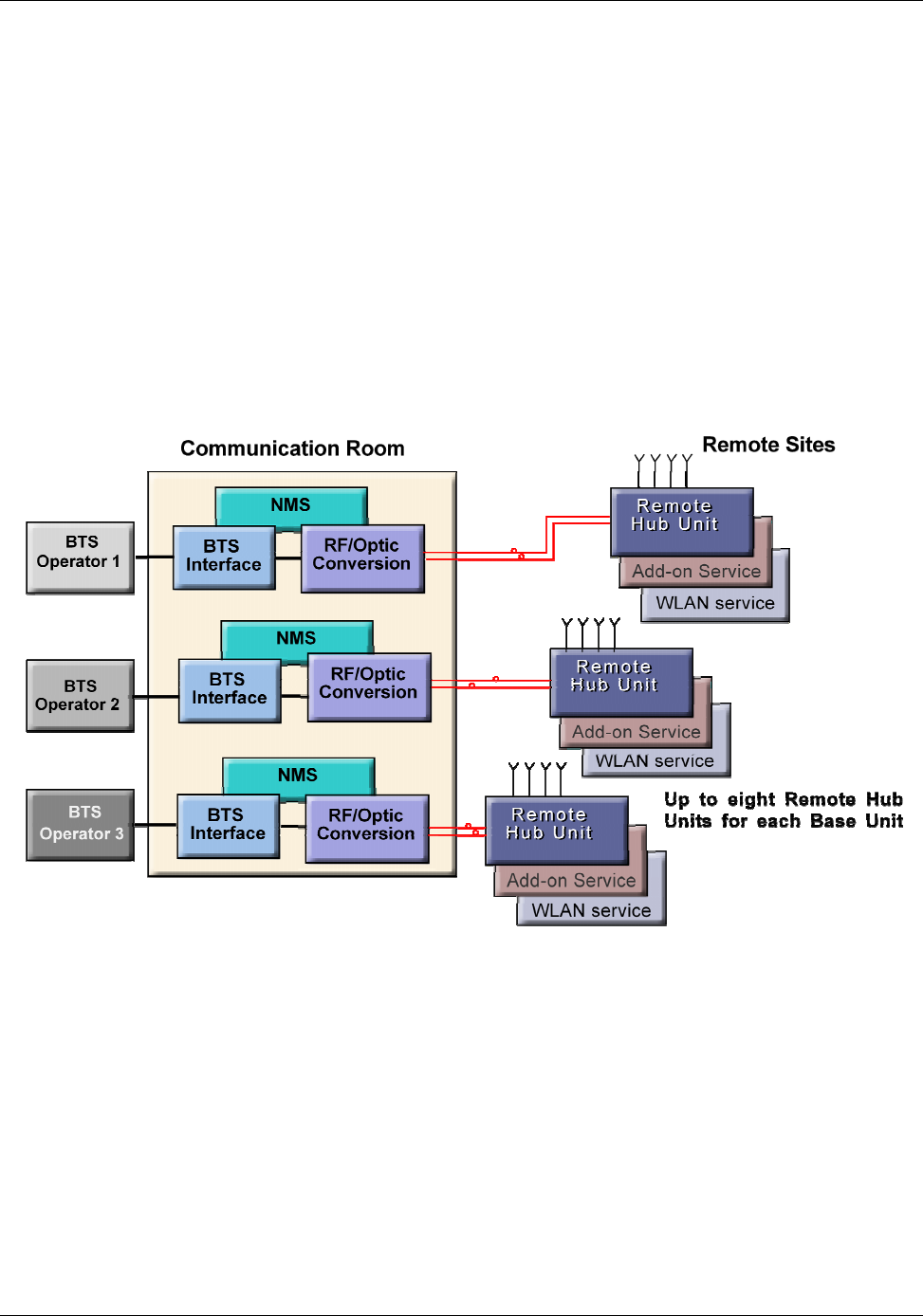
A block diagram of the MobileAccess™ system is given below.
Figure 1-1. MA 1000 System Overview
The Base Units, RF Interface Unit (RIU) and Network Manager controller (NMS) will be installed
in either a Motorola Controller rack or a standard 19-inch wide rack in the communication room
with the RF source equipment, while the RHUs are distributed throughout the locations to be
covered.
MA 1000 Installation and Configuration Guide
4
1.3 Configuration Options
The MobileAccess™ 1000/1200 system includes three basic configuration options:
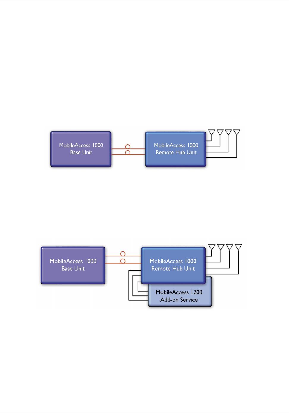
A) Basic configuration
The Base Unit drives a single or dual band, MobileAccess™ 1000 RHU. The dual band RHU
consists of a low band service (cellular 800, iDEN, Paging, or GSM 900) and a high band
service (PCS 1900 or DCS 1800).
Figure 1-2. MobileAccess 1000 Basic BU – RHU Configuration
B) Using the MobileAccess 1200 add-on unit to provide an additional service
A MobileAccess™ 1200 add-on unit can be connected to a MA RHU 2000 unit to provide a
third service. The add-on unit can be Cellular, PCS, UMTS, 3G, or any future service.
Figure 1-3. MobileAccess 1000/1200 BU – RHU Plus Add-On
MA 1000 Installation and Configuration Guide
5
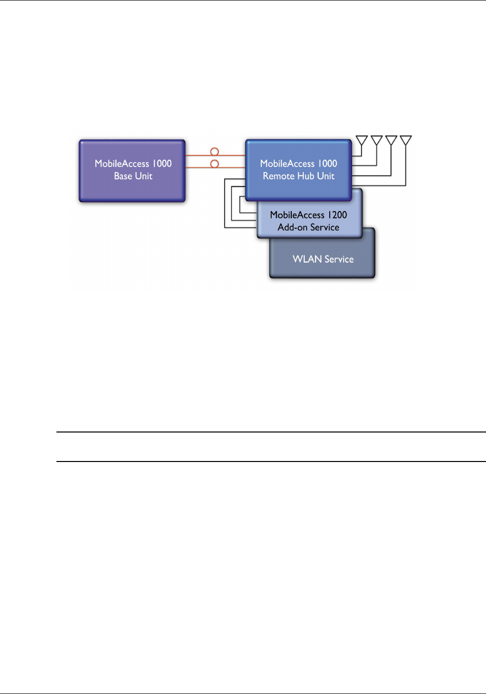
C) Using the MobileAccess 800 WLAN module to provide access to high data-rate
service
A WLAN module (MobileAccess™ 850) may also be added in a configuration that includes
both RHU 1000 and RHU 1200 or only RHU 1000.
Figure 1-4. MobileAccess 1000/1200 BU – RHU Plus Add-on Plus WLAN Configuration
1.4 MA 410/430 Remote Management
The MobileAccess (MA) Network Management System (NMS) provides complete site coverage
and network management. It can be used to provision coverage that can compensate for
changing loads. It also provides real-time monitoring, control and diagnostics capabilities for
MobileAccess
devices from a single location.
NOTE: The MA NMS System is fully described in the MA NMS System Configuration and
Operation Guide.
The MA NMS system consists of:
• MA 410/430 Controller – The controller provides the interface between the system
elements and the management and control mechanism. Two controller models are
available:
• MobileAccess 410™ – enables management of the connected devices through a local or
point-to-point dial-up connection. It can be remotely managed through a connection to
the MobileAccess 430 controller.
• MobileAccess 430™ – enables management of all connected elements and all connected
MA 410 controllers and the corresponding elements. Supports SNMP (Simple Network
Management Protocol) over TCP/IP connection.
• MA 430 may be managed through the Network Operator Center (NOC) through
Manager of Mangers element such as HP OpenView via SNMP.

MA 1000 Installation and Configuration Guide
6
• MCT – a Java based GUI application provided with both controllers. The MCT is used
after the installation procedure to adjust MobileAccess devices according to the
installation site characteristics in order to optimize coverage for the site.
The application is installed and ran from a computer that is connected either locally or via
remote dial-up modem to the controller site to be adjusted or monitored.
• MobileAccess Manager™ – a Java based GUI software application that provides
enhanced monitoring and control capabilities for all your
MA 430™
sites from a single
location; each site can consist of a standalone MA 430 controller, or a MA 430 controller
in a Master topology with a number of MA 410 controllers connected as slaves. The
MobileAccess Manager application is not supplied with the controller – it is
purchased
separately.
The MA NMS application is installed on a server and is accessed from any client by connecting
to the server from any Web Browser with enhanced Java VM capabilities.
MA NMS manager provides the following features and capabilities:
• Remote SNMP management from a single location
• Client/server management capability over a TCP/IP network with enhanced monitoring
and control capabilities
• Intuitive GUI that enables end-to-end fault sourcing from RIU to antennas. The GUI
includes:
• System status at a glance through multi-color tree with upward propagation of fault
indications
• Graphical view of system elements including LED status displays and auxiliary
connections
• Multi-color event monitoring display
• RF Connections
MA 1000 Installation and Configuration Guide
7
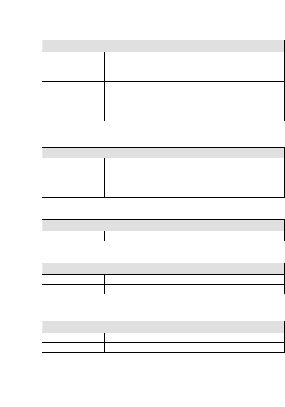
1.5 MobileAccess Models
Table
1-1: MobileAccess™ BU Models
MobileAccess Universal Base Units (1000, 1200, 2000 support)
WB-B8U Wide Band Base 8 Unit supporting 8 RHUs
WB-B4U Wide Band Base 4 Unit supporting 4 RHUs
Table
1-2: MobileAccess™ RHU Models with Add-on Capabilities
MobileAccess 1000 RHUs (ready for add-on units)
1000-CELL-4E Single band-Cellular, 4 ports
1000S-IDEN-4 Single band-iDEN, 4 ports
1000-PCS-4E Single band-PCS 4 ports
1000D-IDEN-PCS4 Dual band-iDEN/PCS, 4 ports
1000D-SMR-PCS4 Dual band-SMR/PAGING/PCS, 4 ports
1000-CELL-PCS4E Dual band-Cell/PCS, 4 ports
1000-CELL-DCS4E Dual band Cell/DCS 4P ready for add-on units
1000-GSM-DCS4E Dual band GSM/DCS 4P ready for add-on units
1000-GSMO-DCS4E Dual band GSM orange/DCS 4P ready for add-on units
1000D-iDEN-SMR4 Dual band iDEN/SMR 4P add-on ready
1000-SMR-FILTER Filter kit for SMR 900
1000-iDEN-SMR4F Dual band iDEN/SMR 4P add-on ready with Filter kit
MA 1000 Installation and Configuration Guide
8
Table
1-3: MobileAccess™ RHU Models
MobileAccess 1000 RHUs (Litenna compatible)
10L-D-IDEN-PCS4 Dual band-iDEN/PCS, 4 ports, LBC
10L-D-SMR-PCS4 Dual band-SMR/PAGING/PCS, 4 ports, LBC
10L-D-CELL-PCS4 Dual band-Cell/PCS, 4 ports, LBC
10L-D-CELL-DCS4 DB Cell/DCS 4P ready for add-on units-LBC
10L-D-CL-M-DCS4 DB Cell multi opr/DCS 4P ready for add-on units-LBC
10L-D-GSM-DCS4 DB GSM/DCS 4P ready for add-on units-LBC
10L-D-GSMO-DCS4 DB GSM orange/DCS 4P ready for add-on units-LBC
Table
1-4: MobileAccess™ 1200 RHU Models
MobileAccess 1200 RHU
1200-PCS-SA-1 Stand Alone high power PCS, one port
1200-UMTS-SA-1 Stand Alone high power UMTS, one port RHU
1200-PCS-AO Add-on RHU supporting a PCS service
1200-UMTS-AO Add-on RHU supporting UMTS service
Table
1-5: MobileAccess™ UMTS Ready RHU Models
MobileAccess 1200 RHU (Litenna UMTS Ready compatible)
12L-UMTS-AO Add-on RHU supporting UMTS service LBC
Table
1-6: MobileAccess™ Controller Models
Network Controller
410 Network Controller – Serial Interface (dial-up)
430 Network Controller –Ethernet/IP Interface
Table
1-7: MobileAccess™ Management System
Network Management System
NMS-SW-SERVER GUI and server S/W package (one per site)
NMS-SW-MFEE NMS annual S/W maintenance fee (per 430-CTLR)
MA 1000 Installation and Configuration Guide
9
Table
1-8: MobileAccess™ RIU
Radio Interface Unit
RIU-IM Radio Interface Unit
RIU-BTSC-CELL BTS Conditioner for Cellular
RIU-BTSC-IDEN BTS Conditioner for iDEN
RIU-BTSC-PCS BTS Conditioner for PCS
RIU-BTSC-SMR BTS Conditioner for SMR-Paging
RIU-BTSC-GSM BTS Conditioner for GSM 900MHz
RIU-BTSC-GSM-O BTS Conditioner for GSM 900MHz for Orange
RIU-BTSC-DCS BTS Conditioner for DCS 1800MHz
RIU-BTSC-UMTS BTS Conditioner for UMTS 2100MHz
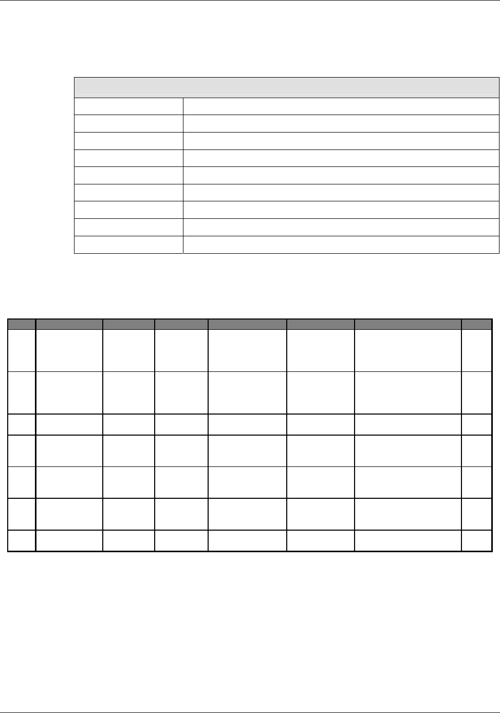
1.5.1 Nextel Item Master Numbers for MobileAccess-1000 iDEN
IM# CCODE NOUN QUALIFIER SUPPLIER NAME Model Number Description Price
25027 DISTRIBUTED RF
EQUIPMENT
IN_BUILDING MAIN MobileAccess WB-B8U (WB-B8U) Wide Band Base 8 Unit
supporting 8 RHUs, 851-866 MHz, 806-
821 MHz, 120/220VAC and 48VDC
$5,411
25028 DISTRIBUTED RF
EQUIPMENT
IN_BUILDING MAIN MobileAccess WB-B4U (WB-B4U) Wide Band Base 4 Unit
supporting 4 RHUs, 851-866 MHz, 806-
821 MHz, 120/220VAC and 48VDC
$2,954
25029 DISTRIBUTED RF
EQUIPMENT
IN_BUILDING MAIN MobileAccess RIU-IM (RIU-IM) Radio Interface Unit,
120/220VAC and 48VDC
$1,750
25030 DISTRIBUTED RF
EQUIPMENT
IN_BUILDING MAIN MobileAccess 410 (NMS-410) Network Controller, Serial
Interface (dial-up), 120/220VAC and
48VDC
$1,050
25031 DISTRIBUTED RF
EQUIPMENT
IN_BUILDING MAIN MobileAccess 430 (NMS-430) Network Controller,
Ethernet/IP Interface, 120/220VAC and
48VDC
$3,500
25032 DISTRIBUTED RF
EQUIPMENT
IN_BUILDING REMOTE MobileAccess 1000S-IDEN-4 (1000S-IDEN-4) Remote Single Band-
IDEN, 4 ports, 120/220VAC and 48VDC
$1,386
25033 DISTRIBUTED RF
EQUIPMENT
IN_BUILDING Accessory MobileAccess RIU-BTSC-IDEN (RIU-BTSC-IDEN) BTS Conditioner for
IDEN, 120/220VAC and 48 VDC $850

MA 1000 Installation and Configuration Guide
10
2
2
S
Sy
ys
st
te
em
m
E
El
le
em
me
en
nt
ts
s
This chapter describes each of the system elements, and their individual connections. It can be
used as reference to verify the connections of each module or to upgrade your system.
2.1 Remote Modules
The Optical to RF conversion of each service at the individual building floors is performed by
remote units corresponding to the service types. These consist of MA 1000 RHUs and in
addition, may include MA 1200 add on modules and MA 850 modules.
The configurations depend on the requirements of the site and the supported services. The
following sections describe each of the system elements.
NOTE: The connections as they relate to the MA 1000 system are described in Chapter
4 -
System Installation.
2.1.1 MA 1000 RHUs
Each RHU supports two different services (one high-band and one low-band). All RHUs are
add-on ready, meaning that their optic interface and control functionality can support a third
(high-power) service through the connections of a MA 1200 Add-on module (see section 2.1.3).
Each RHU 1000 is connected to the corresponding BU (located in the communication room)
through a fiber optic connection. Remote monitoring is provided through the BU connections to
the MA 410/430 controller (see section 2.4).
The RHU 1000 services, MA 1200 add-on service and data services (provided by MA 850 - 2.1.4)
at each location are combined and then transmitted over a common infrastructure to
strategically placed antennas.