Corning Optical Communication MA1K-IDEN-SMR RF Booster User Manual MobileAccess 2000
Corning Optical Communication Wireless RF Booster MobileAccess 2000
Contents
- 1. Users Manual Part 1
- 2. Users Manual Part 2
- 3. Users Manual Part 3
Users Manual Part 2
MA 1000 Installation and Configuration Guide
11
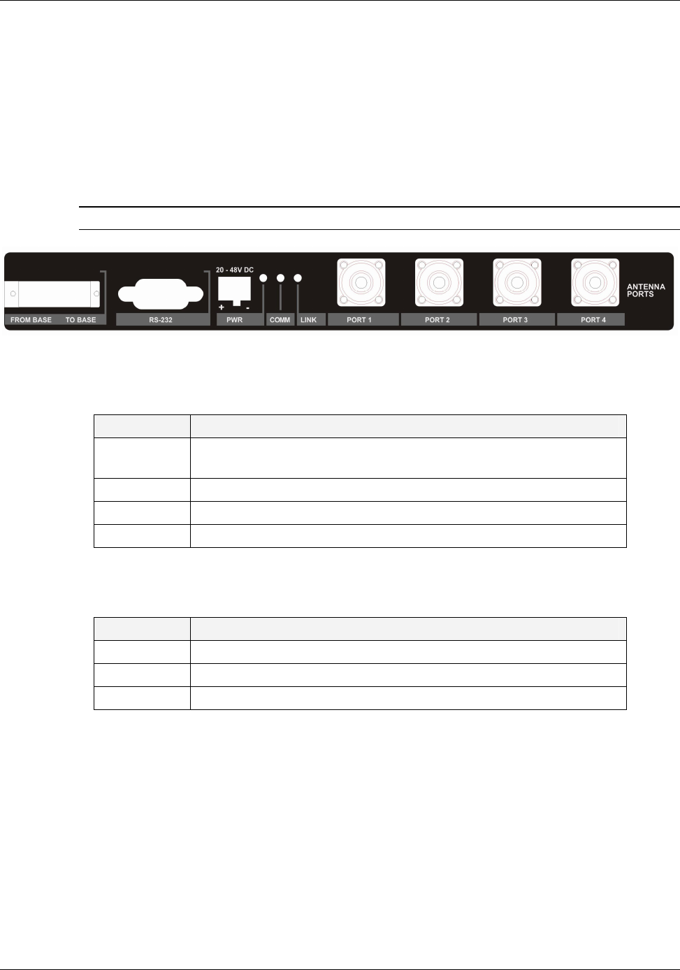
2.1.1.1 RHU 1000 Front Panel
The RHU 1000 front panel contains the fiber optic connections to the BU, four coax connections
to the antennas, power connections and status indicators.
If RHU 1000 and MA 1200 add-on units are installed, then the combined services are fed to the
coax infrastructure through the
RHU 1000 antenna ports
. However, if MA 850 is also installed,
the combined
data and voice
services are fed to the coax infrastructure through the
MA 850
antenna ports
.
NOTE: To provide alarms, the antenna must supply a DC resistance of up to 5K ohms.
Figure 2-1. RHU 1000 Front Panel
Table 2-1. RHU 1000 Front Panel Ports
Port Description
From Base
To Base
Fiber Optic connections to- and from the Base Unit
RS232 Upgrade and service connection (MA service personnel)
PWR DC power connection
Port 1-4 Coax connections to antennas
Table 2-2. RHU 1000 Front Panel Indicators
LED Description
COMM Active communication detected
LINK Optical link to BU detected
PWR DC power connected
MA 1000 Installation and Configuration Guide
12
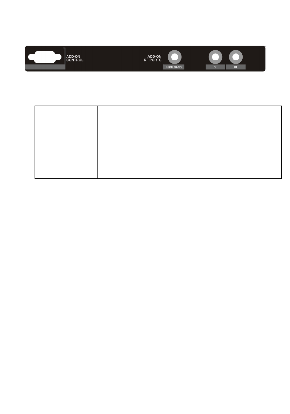
2.1.1.2 RHU 1000 Rear Panel
The RHU 1000 rear-panel provides the connections to an MA 1200 add-on unit.
Figure 2-2. RHU 1000 Rear
Table 2-3. RHU 1000 Rear Panel Connectors
Add-on control Transmits the control signals from MA 1200 add-on module to the
RHU 1000 module. Connected to the MA 1200 add-on Control
From port.
High Band Connects to the 1200 Add-on High Band port. Provides the
interface to the Add-on RF service which is combined with the RHU
services and distributed through the common coax infrastructure.
DL, UL Transmit the RF signals to- and from- the MA 1200 add-on module.
These ports are connected to the corresponding ports on the MA
1200 rear panel: DL to DL, UL to UL.
MA 1000 Installation and Configuration Guide
13
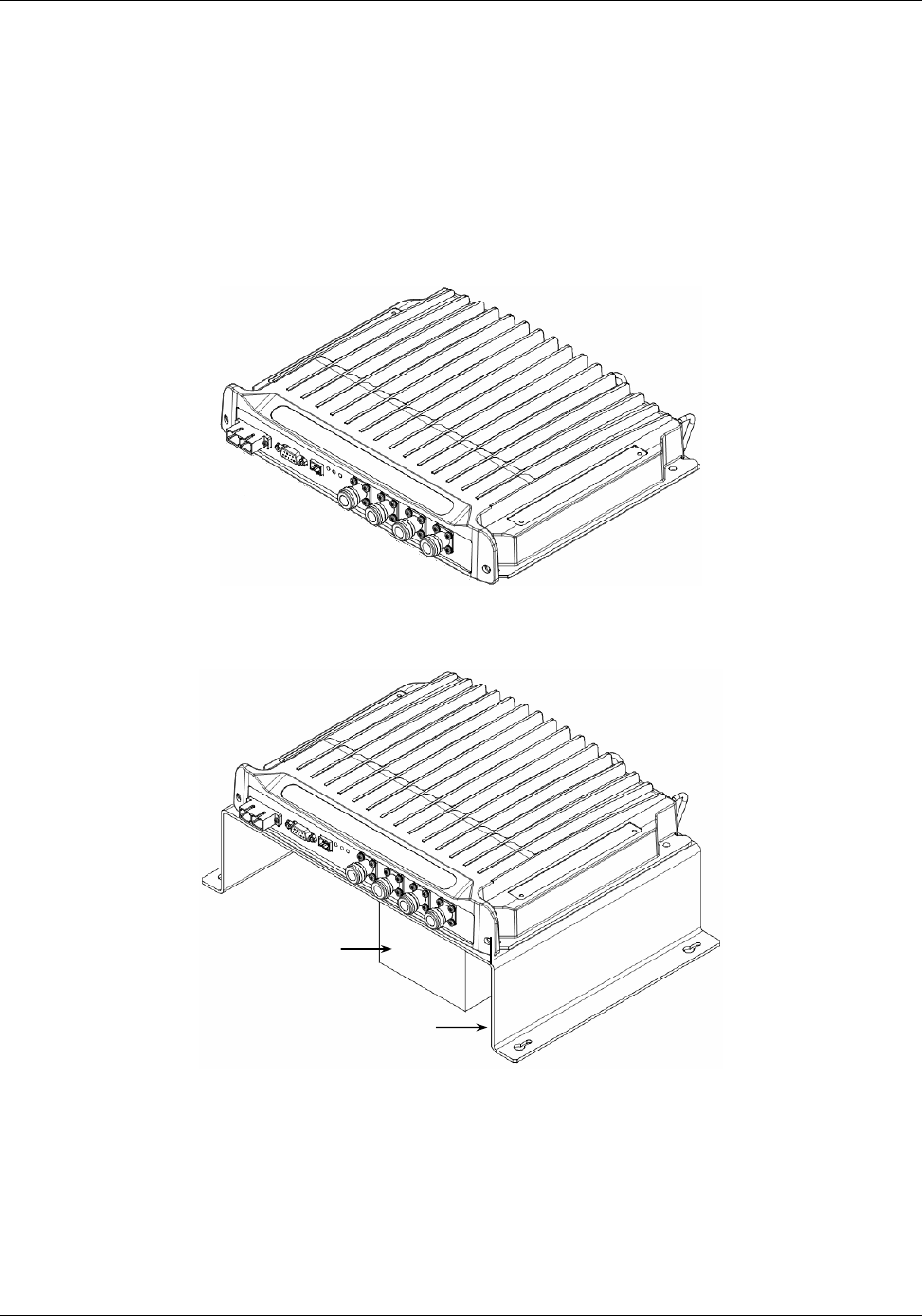
2.1.2 RHU 800/900
RHU 800/900 supports iDEN and SMR technologies. The module is available in the following
configurations:
A) As a
stand-alone module
similar in its physical description, ports, LEDs and installation
procedure to RHU 1000 modules. The standalone module is illustrated below.
B) As a
bracket assembly
that includes the module and the external filter elements as
illustrated below.
Figure 2-3. RHU 800/900 Front View
The following sections provide descriptions of the RHU 800/900 front and rear panel. The
installation of each type of module is described in section 4.3.3.
Bracket
Filter
MA 1000 Installation and Configuration Guide
14
2.1.2.1 RHU 800/900 Front Panel
The RHU 800/900 front panel ports and LEDs is the same as the
RHU 1000 front panel
. Refer
to section 2.1.1.1 for a detailed description of the LEDs and ports.
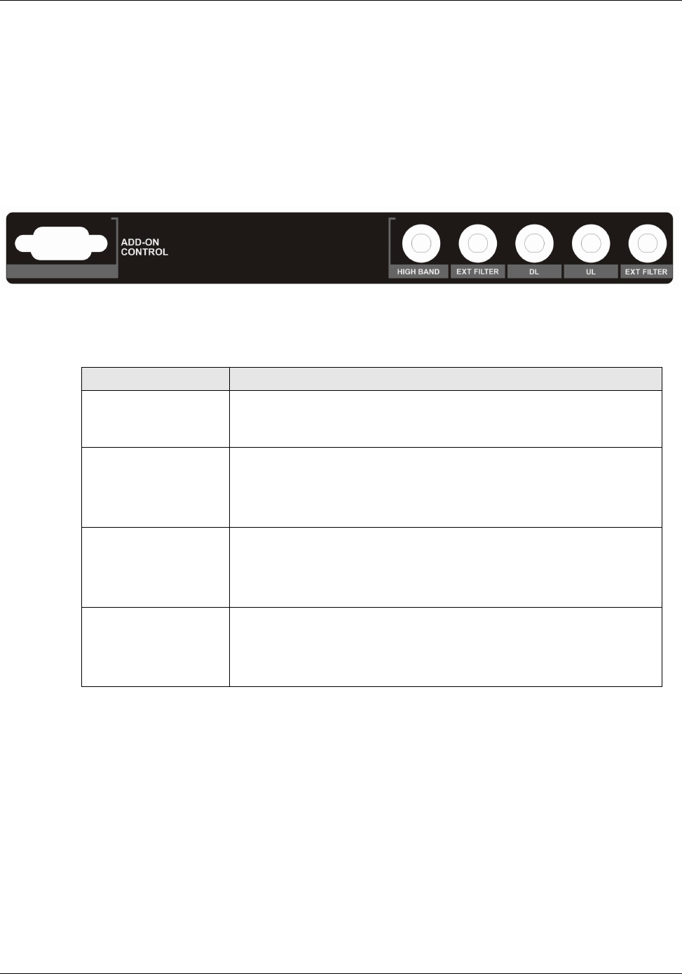
2.1.2.2 RHU 800/900 Rear Panel
The rear panel contains the 1200 add-on and the filter connections.
Figure 2-4. RHU 1000 Rear
Table 2-4. RHU 1000 Rear Panel Connectors
Port Description
EXT FILTER Connections to external filter (as illustrated in the following
section). In installations without a filter, the two EXT FILTER ports
are interconnected with a jumper.
Add-on control Connection to MA 1200 Add-on module.
Transmits the control signals from MA 1200 add-on module to the
RHU 1000 module. Connected to the MA 1200 add-on Control
From port.
High Band Connection to MA 1200 add-on module.
Connects to the 1200 Add-on High Band port. Provides the
interface to the Add-on RF service which is combined with the RHU
services and distributed through the common coax infrastructure.
DL, UL Connection to MA 1200 add-on module.
Transmit the RF signals to- and from- the MA 1200 add-on module.
These ports are connected to the corresponding ports on the MA
1200 rear panel: DL to DL, UL to UL.
MA 1000 Installation and Configuration Guide
15
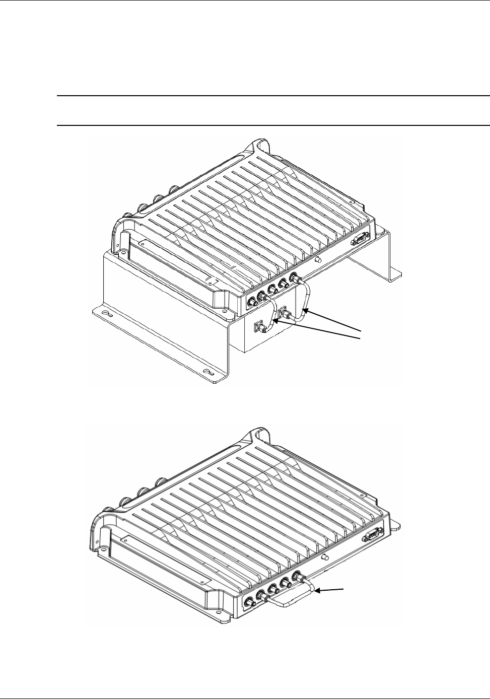
2.1.2.3 RHU 800/900 View of Filter Connection
The following figures illustrate the RHU 800/900 views with and without a filter.
NOTE: Note that the filter port connections are interconnected with a jumper in installations
without a filter.
Figure 2-5. Rear View of RHU 800/900 with Filter
Figure 2-6. Rear View of RHU 800/900 without Filter
Filter connections
Shorted filter connections
since no filter is installed
MA 1000 Installation and Configuration Guide
16
2.1.3 MA 1200 Add-on
The MobileAccess 1200 Add-on module is a high power module, supporting a single frequency
band (low or high). It is designed to be integrated with a host
RHU 1000
module. The RHU
1000 module provides the following functionality for both units:
• Optical interface (to the BU) and conversion
• RF interface (to antennas) and conversion
• Control signals
In addition, MA 850 services can also be combined with MA 1200 add-on and RHU 1000
services. (However, in this type of configuration the combined services interface to the coax
infrastructure through the MA 850 ports.)
NOTE: The units are integrated through simple external cable connections between
corresponding ports.
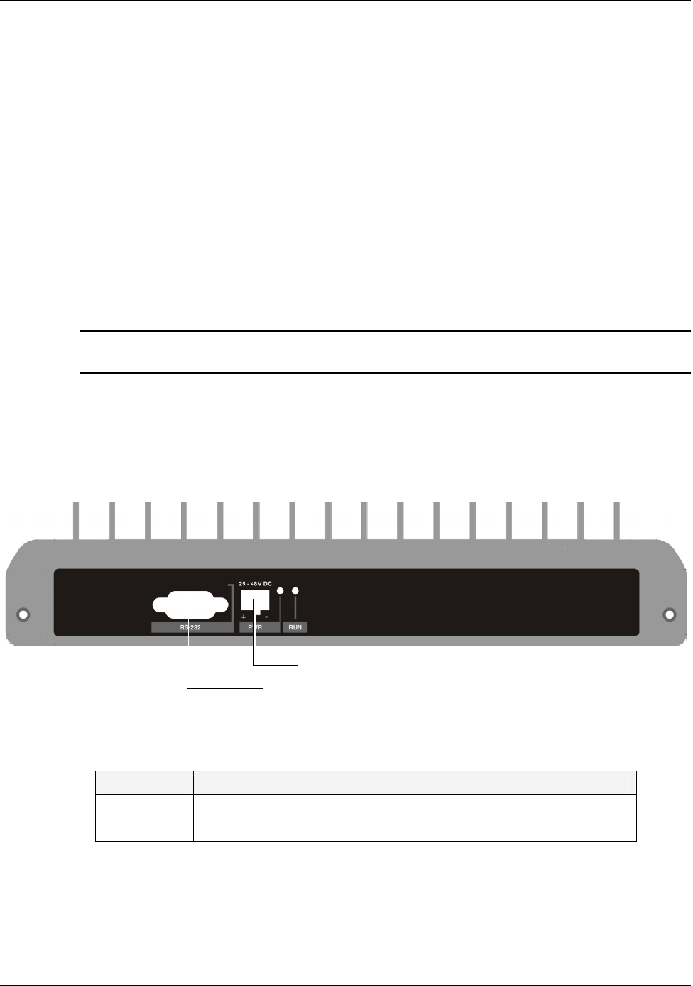
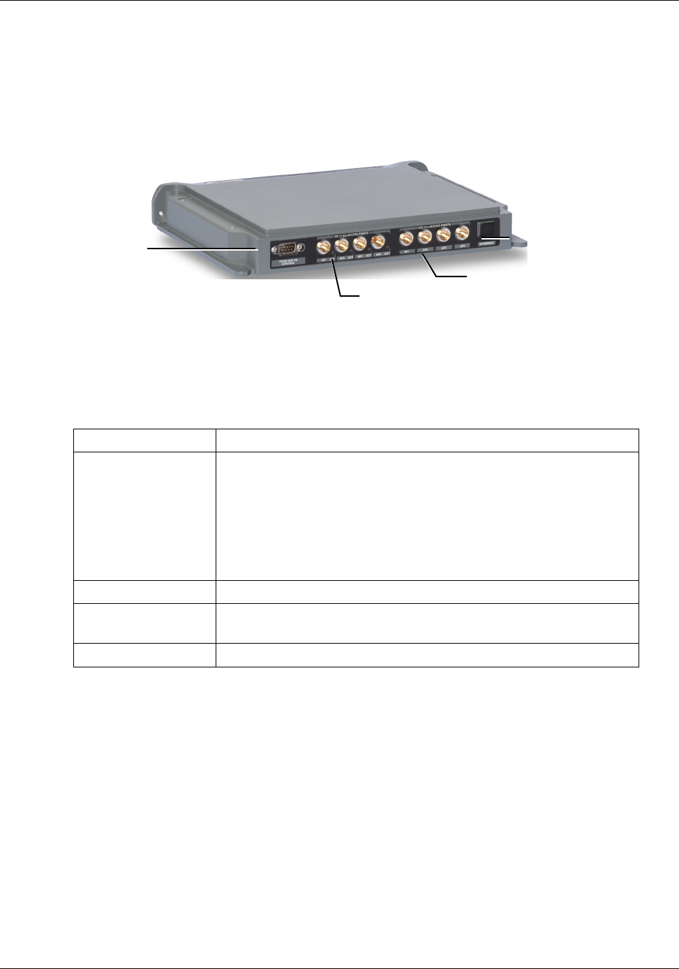
2.1.3.1 MA 1200 Front Panel
The RHU 1200 front panel contains the power connection and status LEDs. (The RS-232
connector is reserved for MA service personnel).
Figure 2-7. RHU 1200 Front panels
Table 2-5. MobileAccess 1200 Front Panel Indicators
LED Description
RUN When blinking, indicates that the RHU is in normal operating mode.
PWR Power ON
MA service connector
Power connector
MA 1000 Installation and Configuration Guide
17
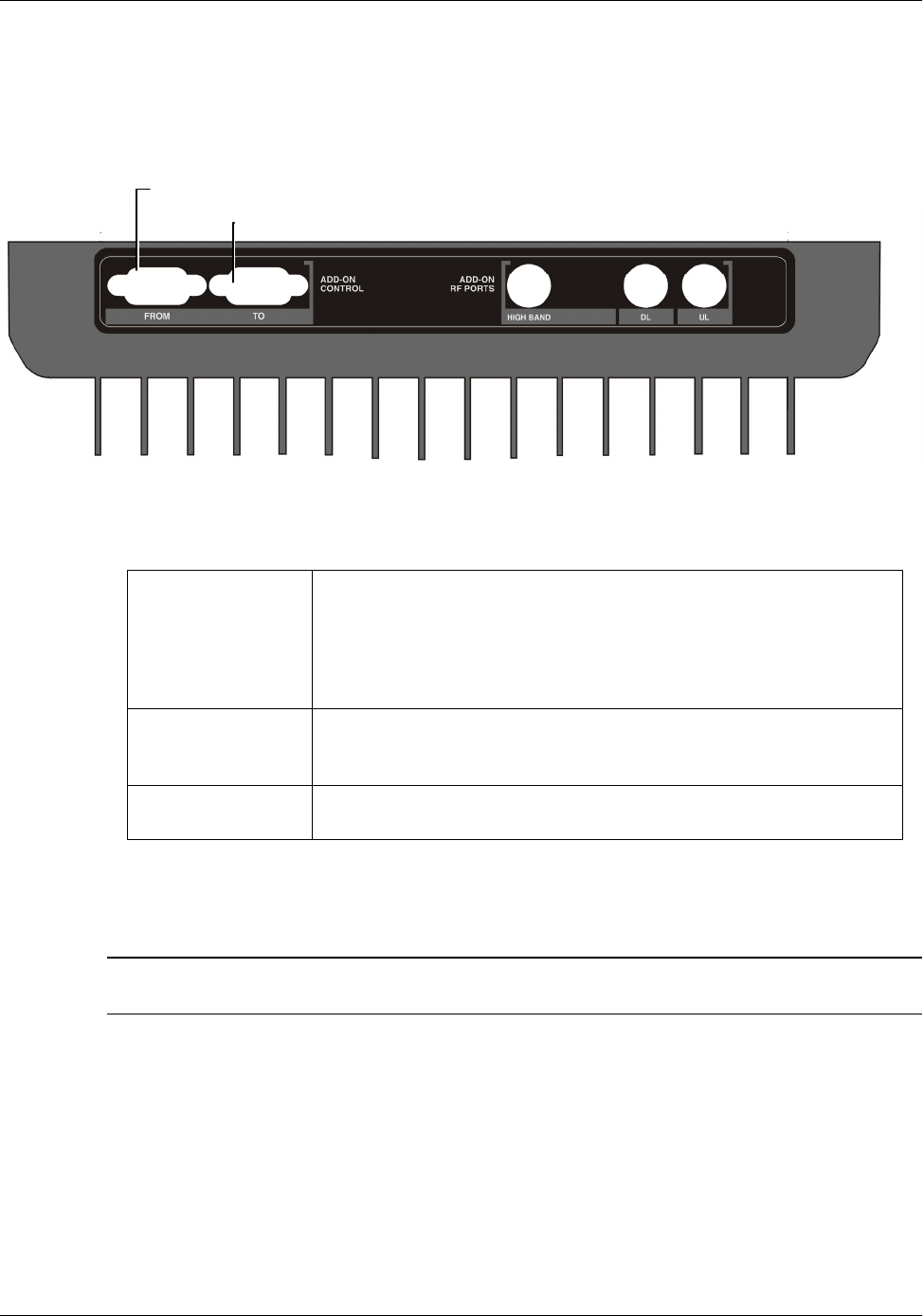
2.1.3.2 MA 1200 Rear Panel
The RHU 1200 rear panel contains the connections to the RHU 1000 and MA 850.
Figure 2-8. RHU 1200 Rear Panel
Table 2-6. RHU 1200 Rear Panel Connectors
Add-on Control Transmits the control signals between the MA 1200 module and the
MA 850 and RHU 1000 modules.
From – receives control signals from the RHU 1000. Connected to
the RHU 1000 Add-on Control connector.
To – Future option.
DL, UL Transmit the RF signals to- and from- the MA 1200 add-on module.
These ports are connected to the corresponding ports on the MA
1000 rear panel: DL to DL, UL to UL.
High RF service output port connected to the RHU 1000 rear-panel High
port.
2.1.4 MA-850 Module
NOTE: This section provides a brief overview of the MA 850 module. For detailed information
on installation and connections, refer to the MA 850 Installation and Configuration Guide.
MobileAccess 850
provides a
secure
and
centralized
connection for 802.11a/b/g Access
Points. It significantly expands 802.11 coverage and enables distributing data and voice services
over the same coax and antenna infrastructure used by MA 1000 system.
MA 850 may be assembled on top of the RHU 1000 or MA 1200 add-on. It is integrated into the
MA 1000 system by interconnecting the appropriate connectors. The combined signals of the
MA 1000 system input to the MA 850 module and then distributed through the same coax
broadband antenna infrastructure
connected to the MA 850.
RHU 1000 Add-on control
MA 850 Add-on control To RHU 1000 High, DL and
UL connectors.
MA 1000 Installation and Configuration Guide
18
MA 850 may be remotely monitored through the RHU 1000 system to which it is integrated, and
remotely configured through a point-to-point Ethernet connection.
The MA 850 front and rear panels, connectors and connections are described in detail in the
following sections.
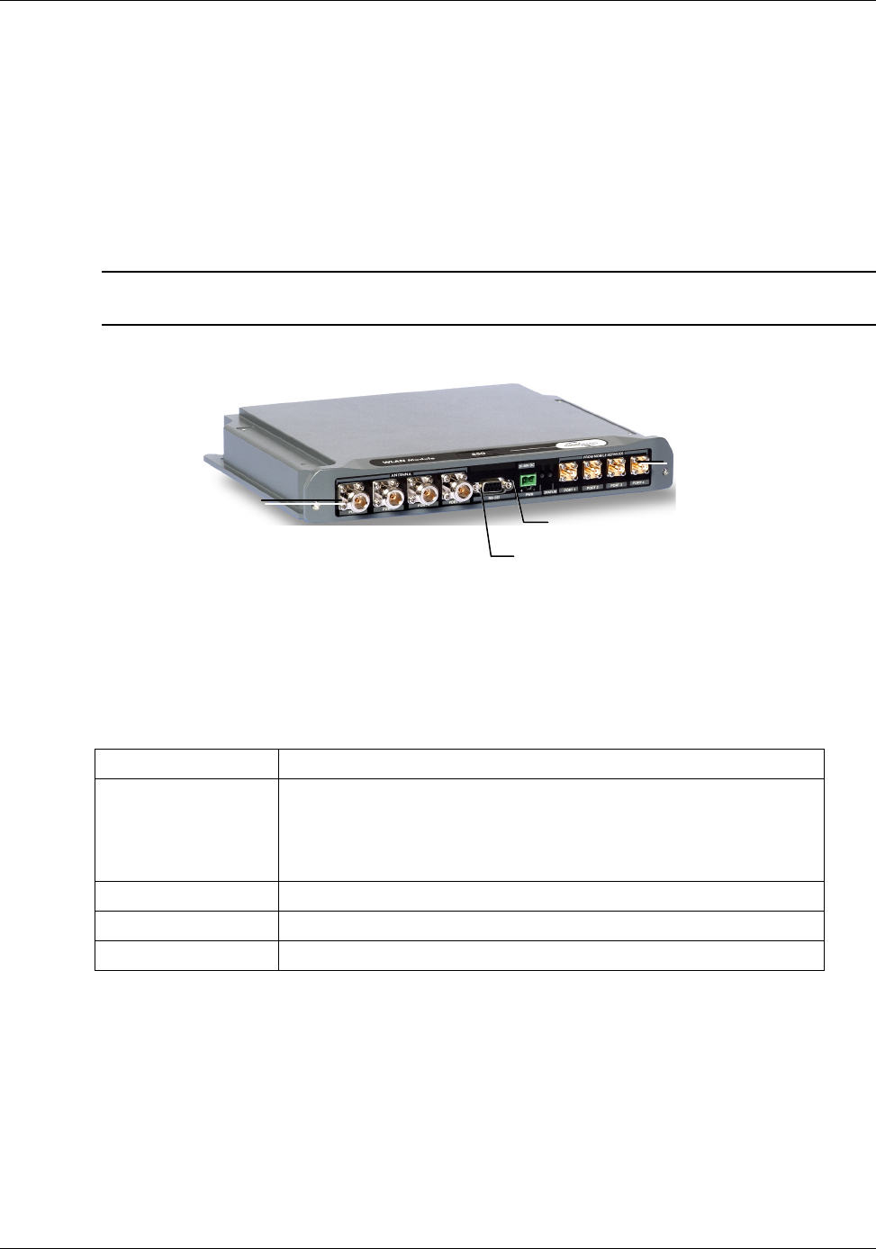
2.1.4.1 MA 850 Front Panel
The MA 850 front panel contains the antenna ports interfaces, local configuration interface and
power connection.
NOTE: Whether connected alone or integrated with RHU 1000 modules, the coax infrastructure
is connected to the MA 850 coax ports.
The following figure shows the MA 850 front panel.
Figure 2-9. MobileAccess 850 Front View
Table 2-7. MA 850 Front Panel Connections
Front Panel Description
Mobile Services Four SMA female connections to which the antenna port of the
MA 1000 system are connected.
To be terminated with 50 ohm terminations when not in
use.
Antenna Ports Four n-type female antenna connections
Local Local connection for setup
DC Power connection: 20V to 48V from a standard power supply
Antenna ports
Connections to
corresponding antenna
ports of remote unit
Local RS232 connection
for configuration
Power
MA 1000 Installation and Configuration Guide
19
2.1.4.2 MA 850 Rear Panel
The MA 850 rear panel contains the connections to the APs, the Ethernet port for remote
configuration and the connection to the MA 1200 add-on control (if an MA 1200 add-on unit is
installed)
Figure 2-10. MobileAccess 850 Rear View
Table 2-8. MA 850 Reart Panel Connections
Rear Panel Description
802.11b,g APs Connection to up to four 802.11b/g APs, where associated LED
Lite under the following conditions:
• Green: indicates where AP should be connected after
configuration
• Green flickering: Link with AP established but no data is
received
• Red: AP transmitting data
802.11a APs Connection to up to four 802.11a APs
Connection to
control
Connection to MA 1200 To connector on the rear panel. Used for
viewing antenna status
Ethernet port Connection to network for Web configuration
802.11 b/g APs
connections
Ethernet
Port
802.11 a APs
connections
Connection to
add-on control
MA 1000 Installation and Configuration Guide
20
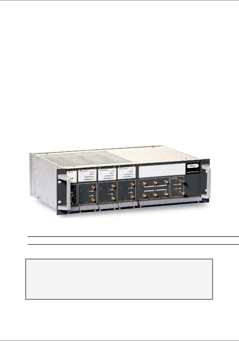
2.2 Radio Interface Unit (RIU)
The RIU is an operator dedicated unit that interfaces to up to three BTS sources and
automatically adjusts the signal output according to changing environmental conditions in order
to provide optimal coverage for the site. The RIU is remotely monitored and managed.
Each RIU can support up to three BTS Conditioner (BTSC) sub-modules, where each sub-
module provides interface to a BTS or BDA of
the same type of service
.
Each RIU can be connected to
four
8-port Base Units (real panel connections) or to
eight
4-port
Base Units.
Additional BUs can be supported by using splitters and combiners connected to the front panel
Expansion connectors.
The following figures shows an RIU with three BTSC sub-modules.
Figure 2-11. RIU
Note: All connections are via RG223 coax cables with 1/2" N-type male connectors
ATTENTION
The RIU is factory set to 0dB gain on the uplink and downlink. In order to operate
properly, an ADJUSTMENT process is required in the field.
Any unused input and output connectors MUST be terminated with 50 ohms –
otherwise the ADJUSMENT procedure results may be affected.
MA 1000 Installation and Configuration Guide
21
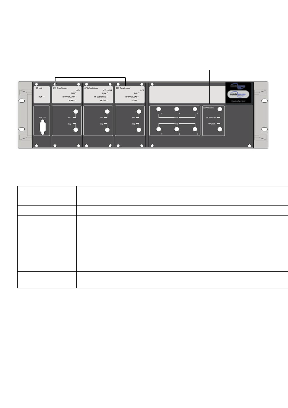
2.2.1.1 RIU Front Panel
The RIU front panel contains the indicators and expansion connectors for the connection of
additional BUs.
Figure 2-12. RIU Front Panel
Table 2-9. RIU Front Panel Indicators
LED Description
P.S UNIT PWR ON – input signal is at the required level.
BTS CONDITIONER RUN Flashing -- CPU is running and software loaded
BTS CONDITIONER DL
OVERLOAD
Continuous Red – RF switch is disconnected to protect the system. This may
be due to:
• Unpredicted power rise for which the attenuation response was
insufficient to compensate and reduce the power to the required level.
• Software problem detected.
Flashing: When the BTSC DL output power is more than 3dB of the calibrated
value.
BTS CONDITIONER DL
LOW
Continuous Red – if the BTSC DL power is at least 15dB lower than the
calibrated BTSC max power level. This condition also triggers an event.
Power Supply BTS Conditioners Expansion connectors - for
connectin
g
additional BUs
MA 1000 Installation and Configuration Guide
22
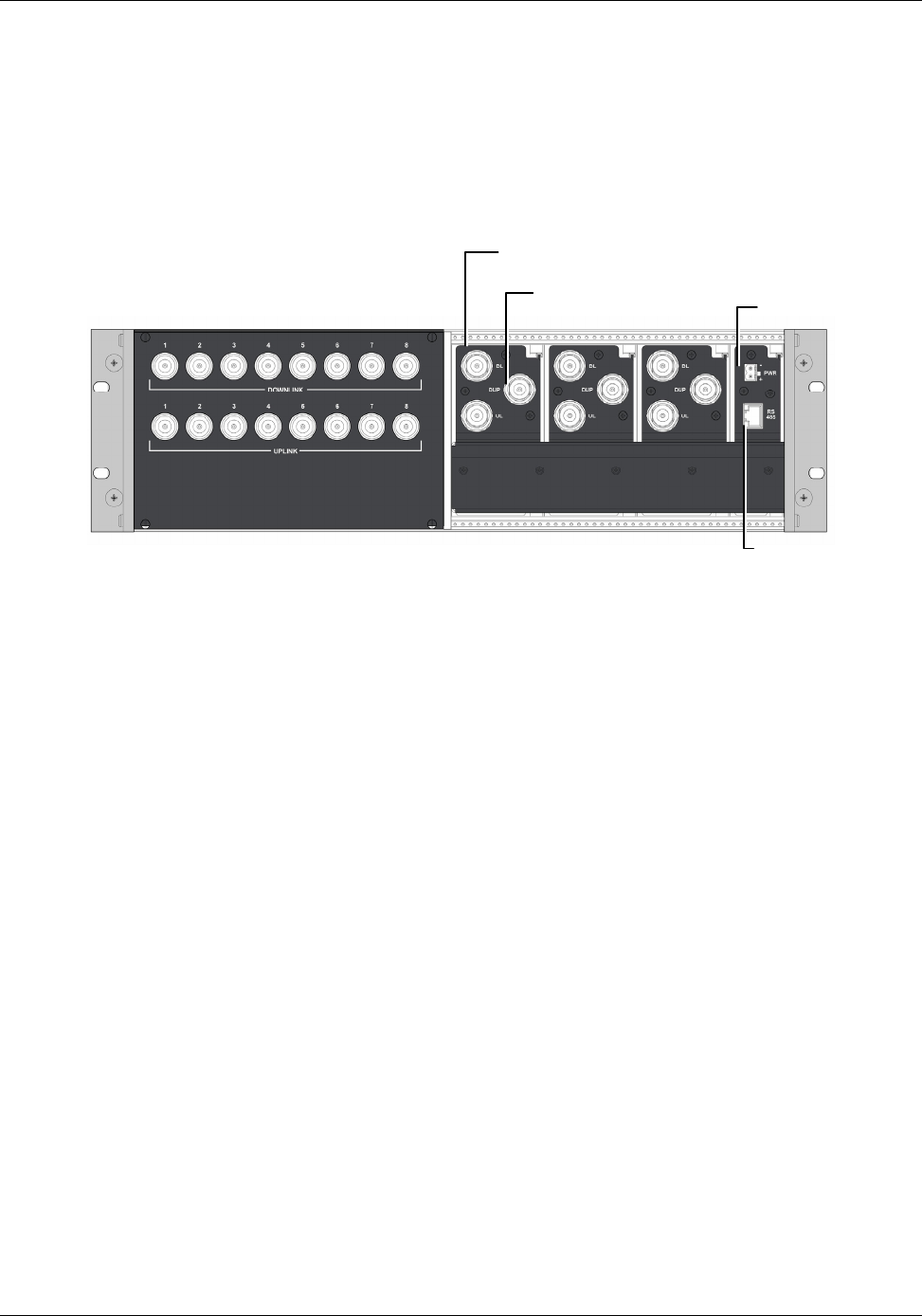
2.2.1.2 RIU Rear Panel
The rear-panel provides all the connections on the BTS side and on the BU side as well as
connections to the MobileAccess 410/430 controller and the power connection. Two types of
BTS side connections are available for each BTS conditioner: simplex and duplex.
Figure 2-13. RIU Rear Panel showing the RF Connection
2.3 MA Base Units
The BUs (Base Units) perform RF to optical conversion of the signal on the BTS/BDA side. Each
can support up to two services (provided by the same operator). Two models of MA BUs are
available: four-port unit – supporting four RHUs, and eight-port unit supporting up to eight
RHUs. The RHU models correspond to the services supplied through the BUs.
The BU (and all the corresponding remote units) may be remotely monitored and managed via
the MA NMS (Network Management System).
The BUs are usually installed in the telecom room adjacent to the BTS/BDA signal source. RF
ports on the rear panel provide interface to the BTS side (through connection to RIU or passive
interface), while optic ports on the front panel provide interface to the RHUs (Remote Units).
This following sections describe the MA BU front and rear panels, including indicators and
connectors.
BU connections; one UL and one DL
connection for every group of four
ports (single OPTM) on the BU. Power
MA Controller
connection
BTS/BDA simplex connections
BTS/BDA duplex connections
MA 1000 Installation and Configuration Guide
23
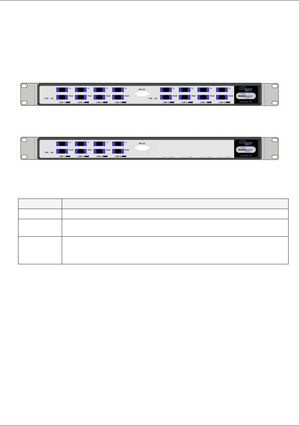
2.3.1.1 MA BU Front Panel
The front panel contains the optical connections and indicators. The BU is available in two
configurations: Four-port - and Eight-port BUs. The eight-port BU consists of two four-port
elements where each four-port element has a dedicated set of indicators (PWR, LSR and Link 1
to Link 4 or Link 5 to Link 8).
Figure 2-14. Eight-Port MA BU Front Panel
Figure 2-15. Four-Port BU Front Panel
Table 2-10. MA BU Front Panel Indicators
LED Description
PWR Power input detected for the corresponding unit.
LSR ON - laser circuitry for the corresponding element (group of four ports) is
functioning correctly.
Link 1-4, 5-8 ON - the optical link to/from the connected remote functions within the
specifications in both directions.
Blinking - optical power from remote is lower than expected by at least 2 dBm
Four ports and corresponding indicators Four ports and corresponding indicators
MA 1000 Installation and Configuration Guide
24
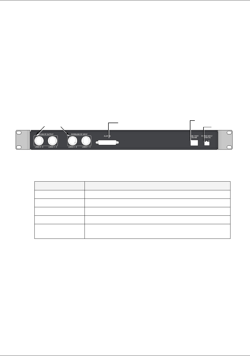
2.3.1.2 BU Rear Panel
The BU rear panel contains the RF, Alarms, NMS and power connections. Note that there are
two uplink and two downlink RF connections to the BTS side (to an Interface Box or RIU) - each
individual uplink and downlink connection corresponds to a four-port BU element. For a four-
port BU, one uplink and one downlink port is connected; for an eight-port BU, two uplink and
two downlink ports are connected.
For systems that include MA 430 controllers, the RS 485 port is connected to the MA 410/430
controller to enable remote monitoring and management of the BU from a central location. For
systems without remote management, the Alarms dry-contact connector pins can be connected
to the BTS to provide alarms functionality.
Figure 2-16. MA BU Rear Panel (RF Connections)
Table 2-11. MobileAccess 1000 Rear Panel Connections
Connector Description
Uplink output Uplink connectors to be connected on BTS side.
Downlink input Downlink connectors to be connected on the BTS side.
Com Port RS485 Connection to MobileAccess 410/430 controller.
PWR Power connection
Alarms Dry-contact connections to BTS/BDA (normally closed).
Relevant only for system without MA 410/430 controllers.
Pair of uplink and downlink RF
connections for interface to BTS Alarms dry-
contact
t
MA 410/430
Power
MA 1000 Installation and Configuration Guide
25
2.4 MobileAccess NMS System
NOTE: This section provides general information on the MobileAccess 410/430 Controller. For
detailed information on the controller, configuration and connections refer to the Mobile Access
NMS User
’
s Guide.
The MobileAccess controllers enable managing and controlling the MobileAccess system
elements. All the monitoring and control operations can be performed from the Master’s
location.
Two MobileAccess controller configurations are provided: MobileAccess 410 and MobileAccess
430. The models differ in their remote access capabilities:
• MobileAccess 410 provides point-to-point connectivity implemented via either direct
RS232 connection or via connection to a DSPN phone line
• MobileAccess 430 provides client/server management capability over TCP/IP network
with enhanced monitoring and control capabilities (in addition to the connectivity
options provided by MobileAccess 410).
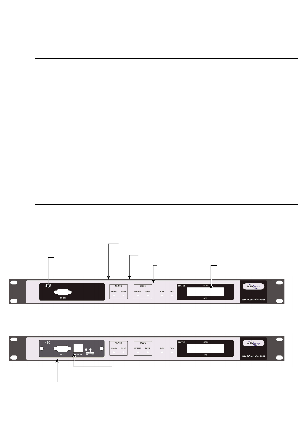
NOTE: The MobileAccess 430 front panel is differentiated from the MobileAccess 410 front
panel by the SNMP Agent Card that provides TCP/IP management capabilities.
Controller Front Panel
Figure 2-17. MobileAccess 410 Front Panel
Figure 2-18. MobileAccess 430 Front Panel
Local RS232
connection (for IP
address setu
p)
LCD alarm display
corresponding to Major
and Minor LEDs
Major, Minor LED
indicators
Master/Slave configuration
Run and
Power LEDs
T
CP/IP connection
Local RS232 connection to Laptop
(MA 300 for Remote controller)
MA 1000 Installation and Configuration Guide
26
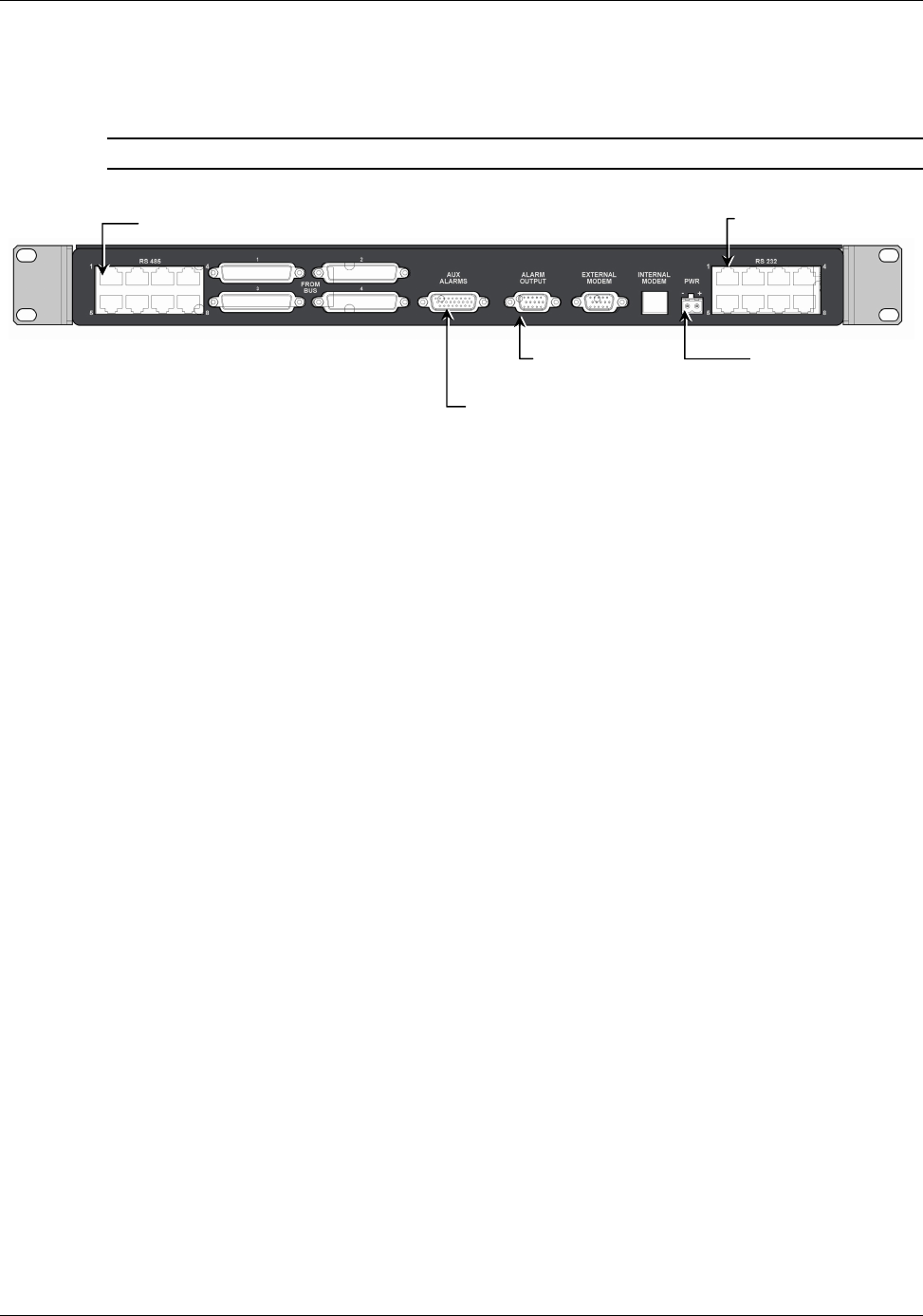
Controller Rear Panel
Note: The rear panels for the MobileAccess 410 and MobileAccess 430 are the same.
Figure 2-19. MobileAccess 410/430 Rear Panel
DC In
p
ut
General purpose
alarms input (MA 300).
BTS alarms output
MA BU and RIU
inputs
Slave controller
connections

27
3
3
S
Si
it
te
e
P
Pr
re
ep
pa
ar
ra
at
ti
io
on
n
3.1 Infrastructure Preparation
This following installation rules are based on the assumption that site survey and installation
planning (
including power requirements
) have been completed.
3.2 Installation Requirements
The infrastructure preparation consists of two main phases:
A. Floor Planning: Planning the distribution of the antennas on each floor to provide the
required coverage.
B. Telecom Closet Planning: Planning the layout of the devices and cables in the telecom
closet or shaft. This includes the MA 850, 802.11 Access Points, cabling and other voice
service distribution systems that are relevant to the specific installation.
3.3 Coaxial Cable Connections
3.3.1 General Cable Installation Procedures
Observe the general cable installation procedures that meet with the building codes in your
area. The building code requires that all cabling be installed above ceiling level (where
applicable). Each length of cable from the risers to each antenna must be concealed above
ceiling.
The cable must be properly supported and maintained straight using tie-wraps, cable trays and
clamps or hangers every 10 feet (where practical above ceiling level). Where this is not
practical, the following should be observed:
• The minimum bending radius of the supplied ½” coax cable should be 7”.
• Cable that is kinked or has a bending radius smaller than 7” must be replaced.
• Cable runs that span less than two floors should be secured to suitably located
mechanical structures.
• The cables should be supported only from the building structure.

MA 1000 Installation and Configuration Guide
28
3.3.2 Fiber Optic Rules
• Use only single mode fiber for indoor applications.
• Use only 8-degree SC/APC connectors (green color).
• Use only fusion splice for connecting two fibers.
• Use minimum splicing/connectors to achieve minimum losses on the fibers (<0.5dB).
• Use precaution while installing, bending, or connecting fiber optic cables.
• Use an optical power meter and OTDR for checking the fiber optic cables.
• Make sure the environment is clean while connecting/splicing fiber optic cables.
• All fiber optic connections should be cleaned prior to attaching to termination points
using a dry cleaning device (i.e. Cletop or equivalent).
• Fiber connector protective caps should be installed on all non-terminated fibers and
removed just before they are terminated.
• Verify the Fiber Optic connections. You may use the Optical Test Procedure described at
the end of this manual.
• Pay special attention while connecting the SC/APC connectors - you must hear the
“click” when the connection is made.
3.3.3 RF Rules
• Use coax RG223, 50ohm, male-to-male N-type for RF connections from the
BUs to the BTS/RBS and to the RIU.
• When using the MobileAccess™ system in an environment in which other indoor
coverage systems are installed, it is recommended (where possible) that the antennas
are placed at least two meters apart
• When bending coax cables, verify that the bending radius does not exceed the coax
specifications.
• Use wideband antennas supporting a range of 800Mhz to 2500Mhz
• Use a VSWR meter (i.e. Site Master or equivalent) for checking coax cables, including
the antennas. (<2). The VSWR must be measured prior to terminating the RHUs in the
remote communication rooms
• Terminate all unused RHU and RIU ports with a 50 ohm load

MA 1000 Installation and Configuration Guide
29
3.3.4 Coax Cable Lengths and Losses
Use coax ½”, 50ohm, male-to-male N-type, (6-7dB for 1Ghz, 11dB for 2Ghz) for connecting to
RHU and RHU ports.
Coax Length coax Loss (900Mhz) connector loss Total Loss
30 0.7 1.5 2.2
40 0.9 1.5 2.4
50 1.1 1.5 2.6
60 1.3 1.5 2.8
70 1.5 1.5 3
80 1.7 1.5 3.2
90 1.9 1.5 3.4
100 2.1 1.5 3.6
110 2.3 1.5 3.8
120 2.5 1.5 4
130 2.7 1.5 4.2
140 2.9 1.5 4.4
150 3.1 1.5 4.6
160 3.3 1.5 4.8
170 3.5 1.5 5
180 3.7 1.5 5.2
190 3.9 1.5 5.4
200 4.1 1.5 5.6
MA 1000 Installation and Configuration Guide
30
3.3.5 Power Consumption, Connections and Power Supplies
3.3.6 Power Safety Instructions
SAFETY WARNINGS
• When installing or selecting the power supplies:
• Be sure to disconnect all power sources before servicing.
• Battery replacement in units - only the MA 410/430 controller has batteries. MA
410/430 Controller lithium type battery should only be replaced by MobileAccess service
personnel. Risk of exploding if battery is replaced by an incorrect type. Dispose
of used batteries according to the instructions.
• Calculate the required power according to the requirements of the specific installation
and then determine the configuration of the power supplies. The required DC cables will
then be determined by the selected PS configuration.
• Use only UL approved power supplies
• AC and DC power supply cables – use only the power cords supplied with the units
• Install external over-current protective devices for the system according to the
requirements described in section 3.3.9.
3.3.7 Power Consumption of Units
Table
3-1. MobileAccess™ Power Requirements
Unit Type Voltage Input Typical Power
Consumption
Maximum Current
Consumption
Remote Unit 1000 20 to 48VDC 25W 1.25A
Add-on Unit 1200 25 to 48VDC 50W 2.0A
RIU 20 to 48VDC 12W 0.6A
Base Unit 20 to 48VDC 14W 0.7A
410/430 Controller 20 to 48VDC 10W 0.5A
MA 850 20 to 48VDC 20W 1.0A