Corning Optical Communication MA850A1 In Building RF Distribution System User Manual Revision 1
Corning Optical Communication Wireless In Building RF Distribution System Users Manual Revision 1
UserManual.wiki
>
Corning Optical Communication
>
MA850A1 User Manual
Users Manual Revision 1
Navigation menu
Upload a User Manual
Namespaces
Wiki Guide
HTML
PDF
Info
Views
User Manual
Discussion / Help
Navigation


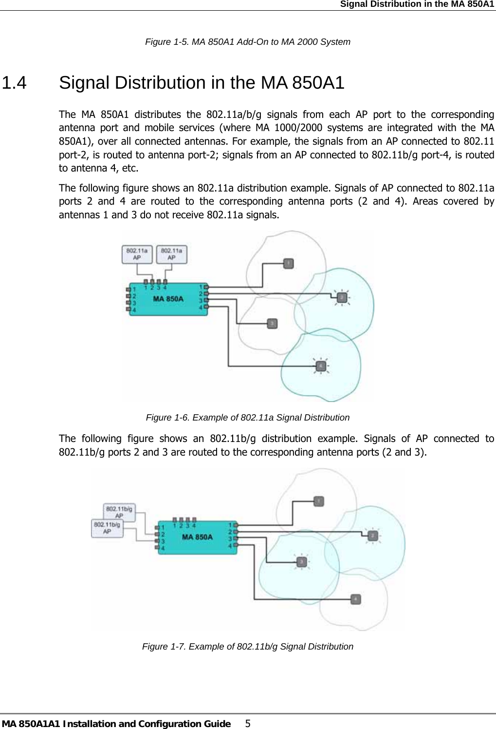
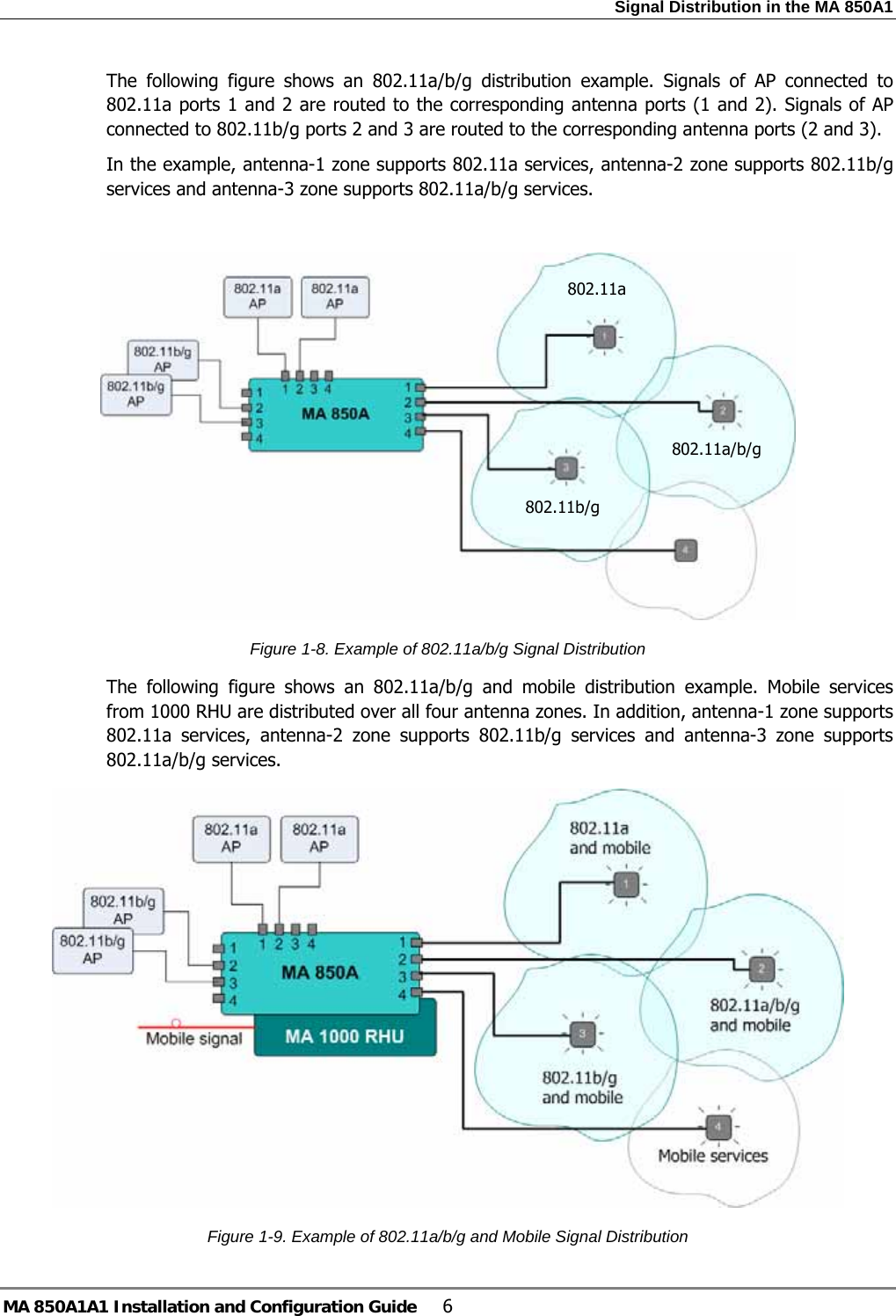
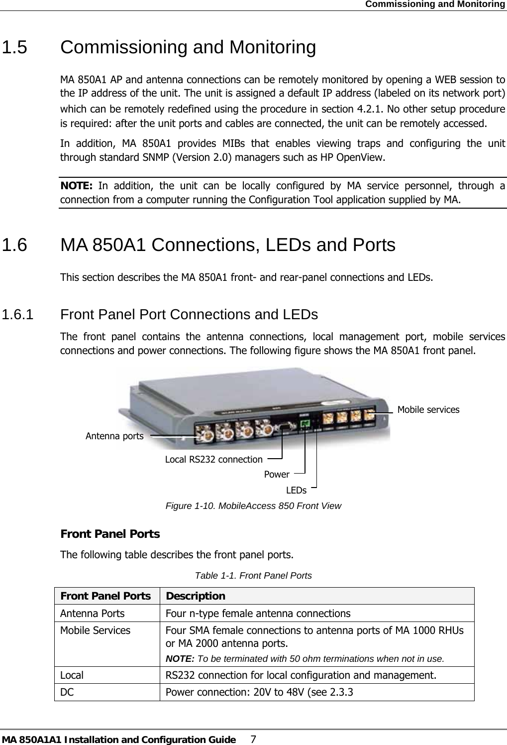
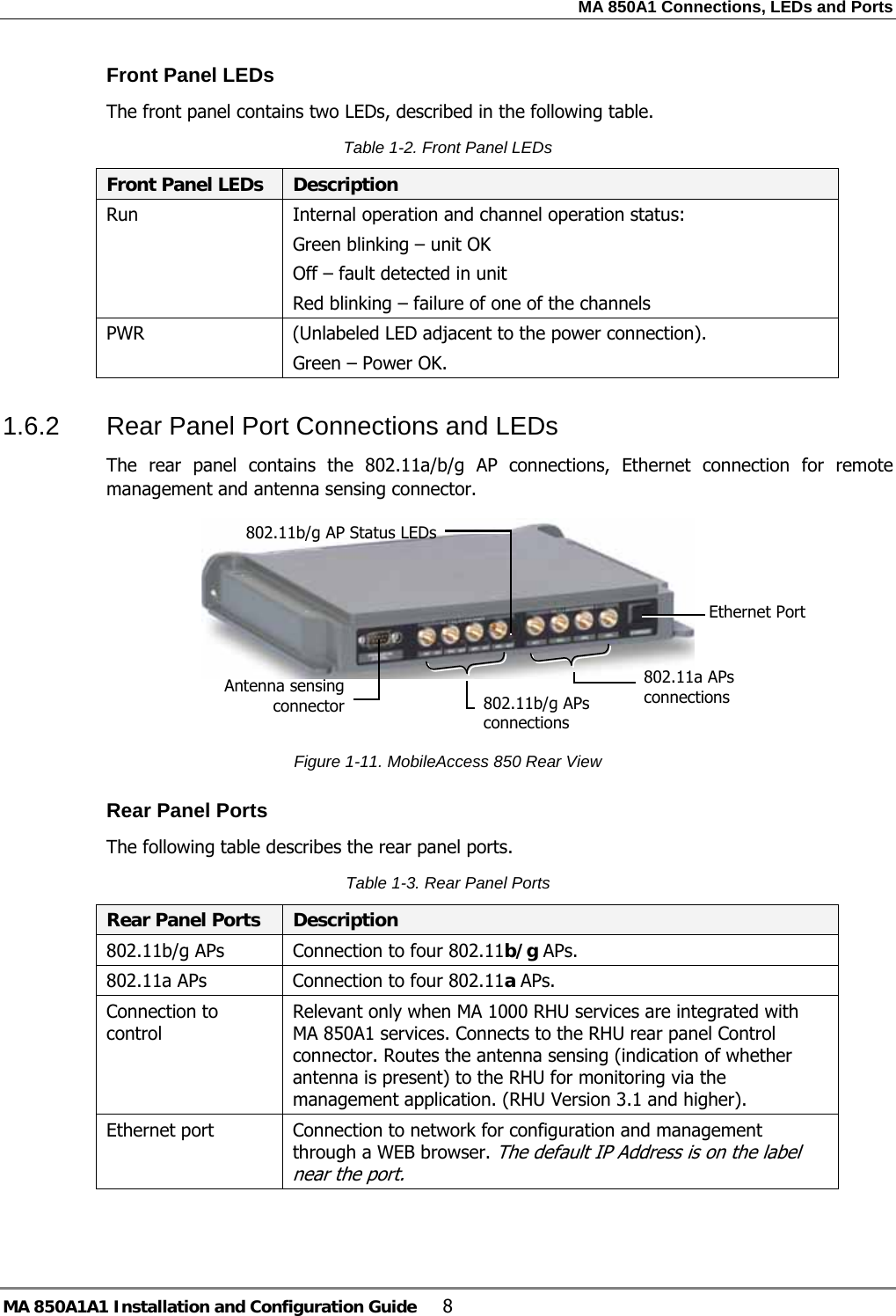
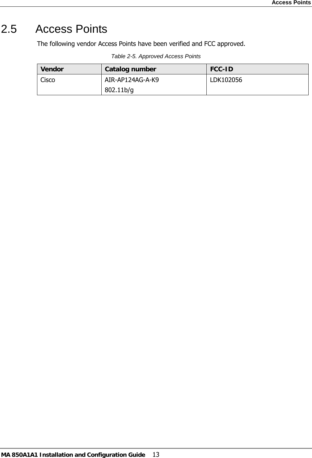
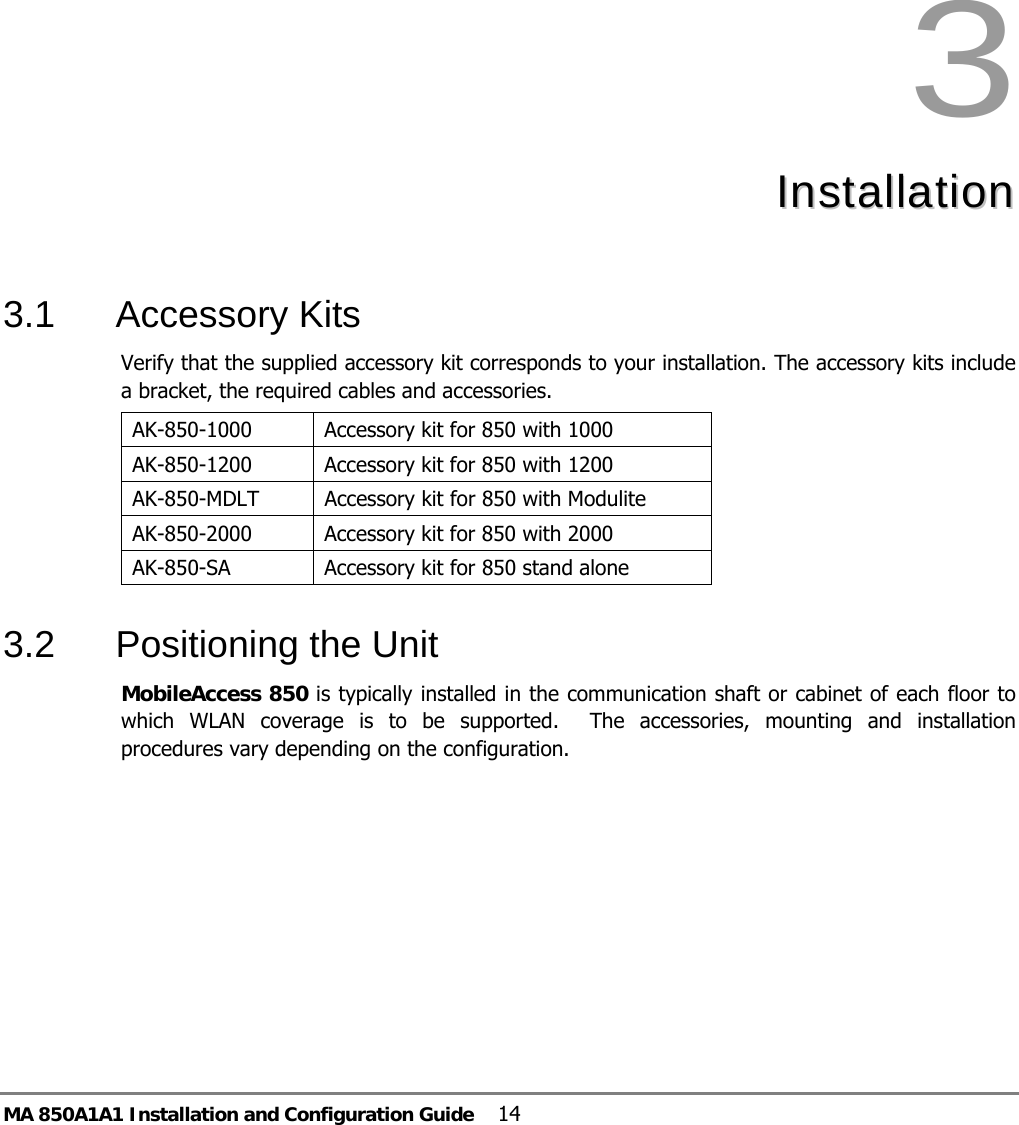
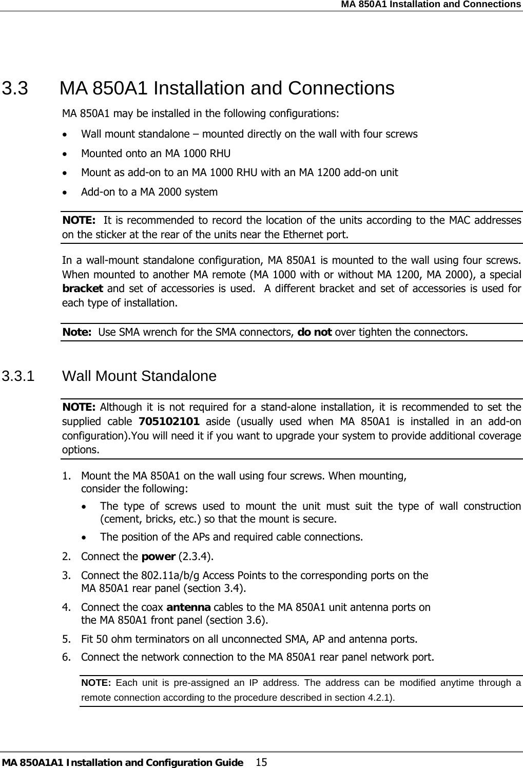
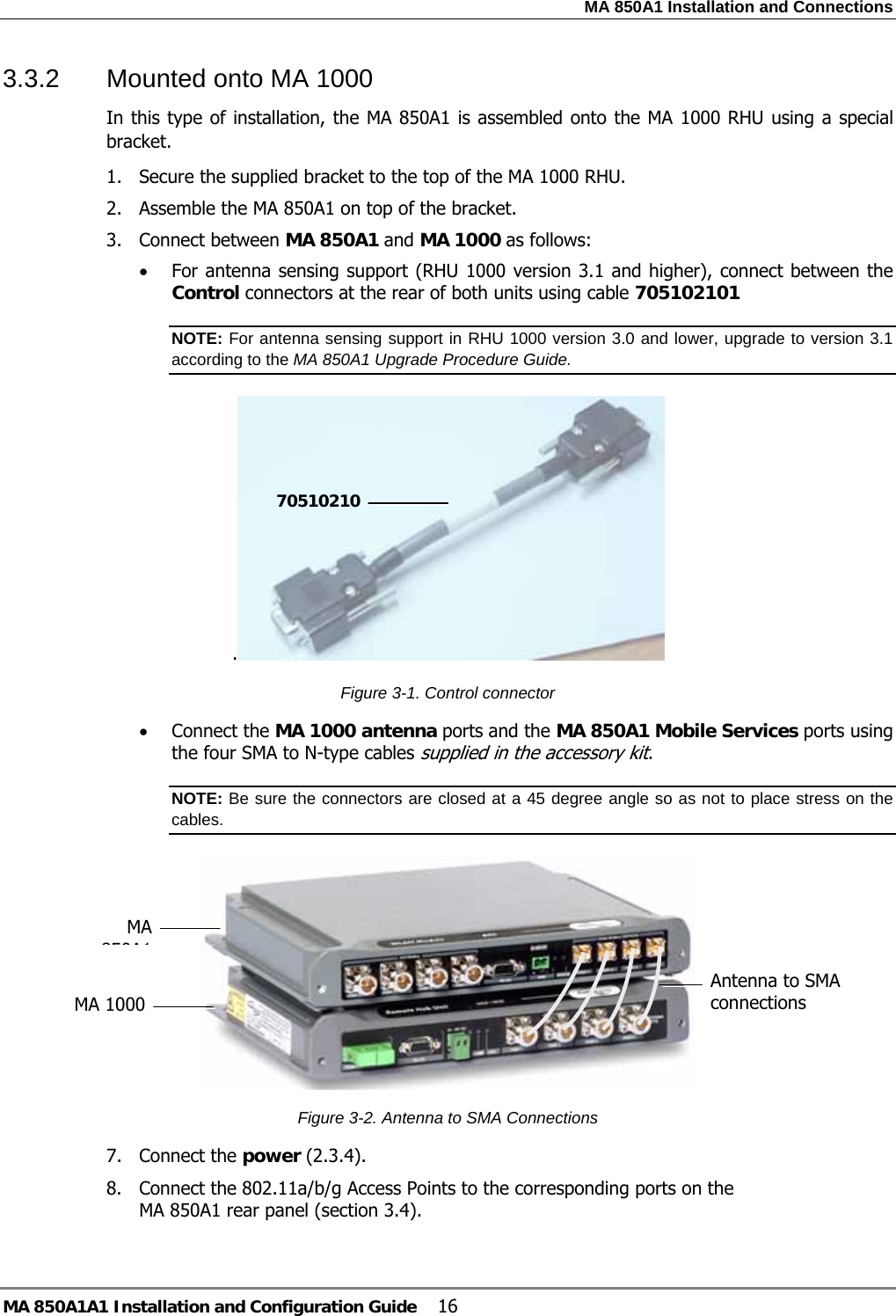
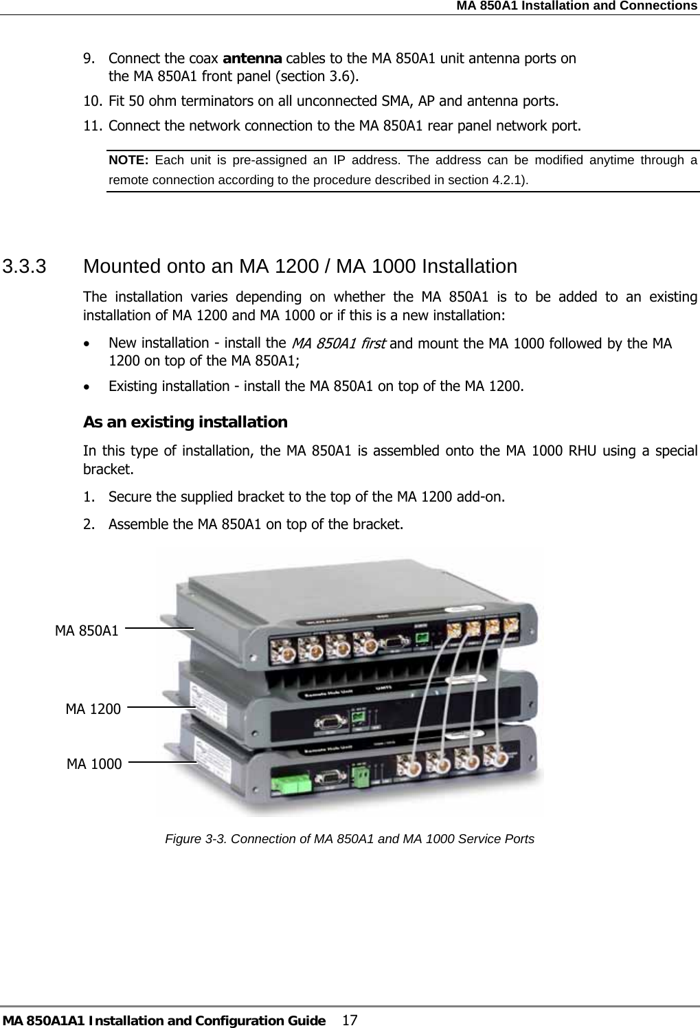
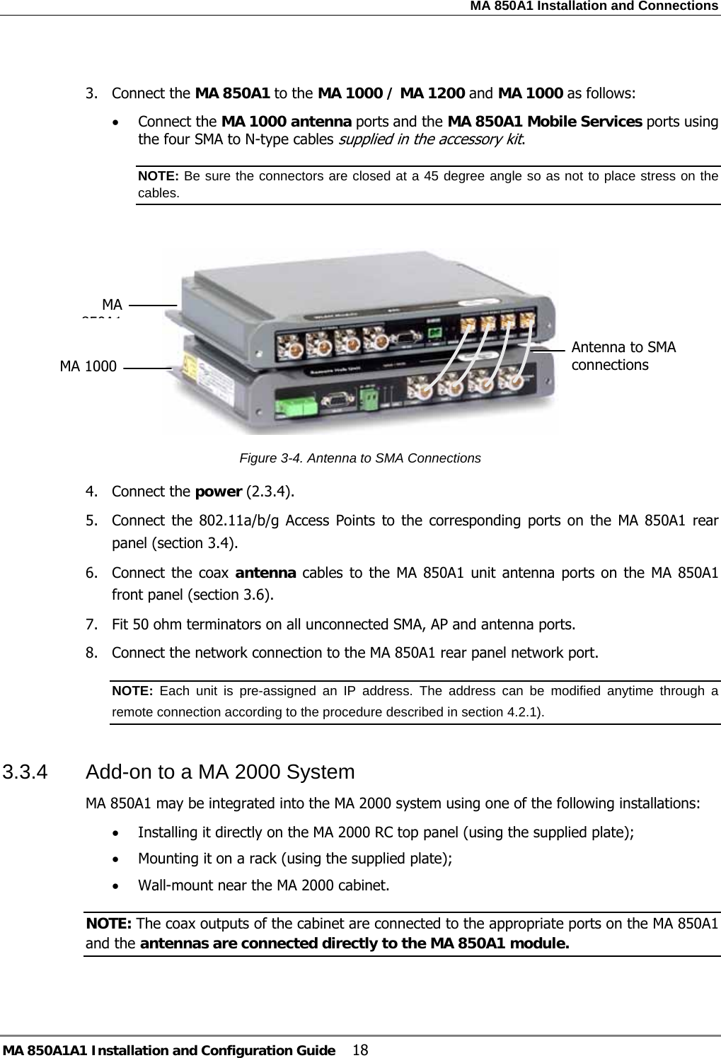
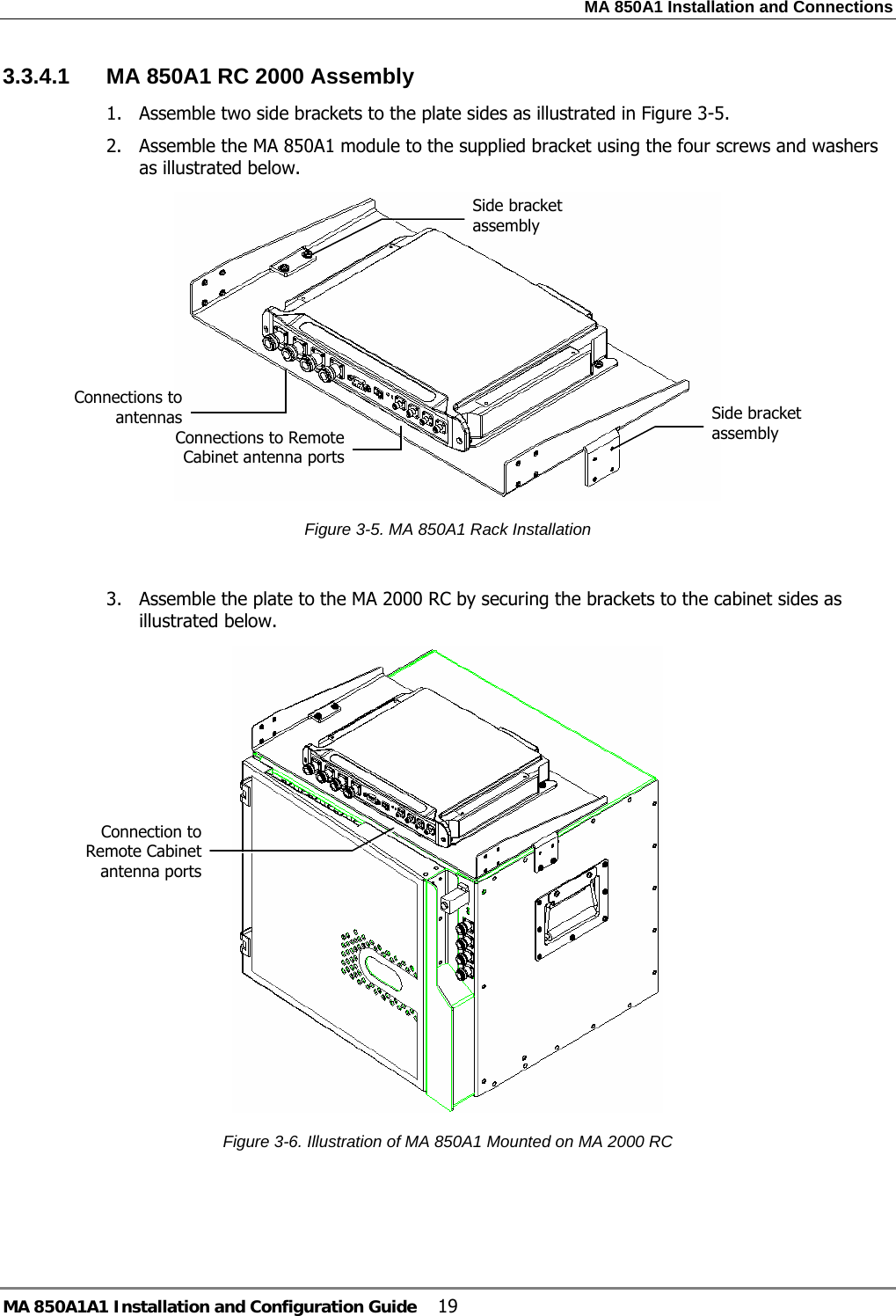
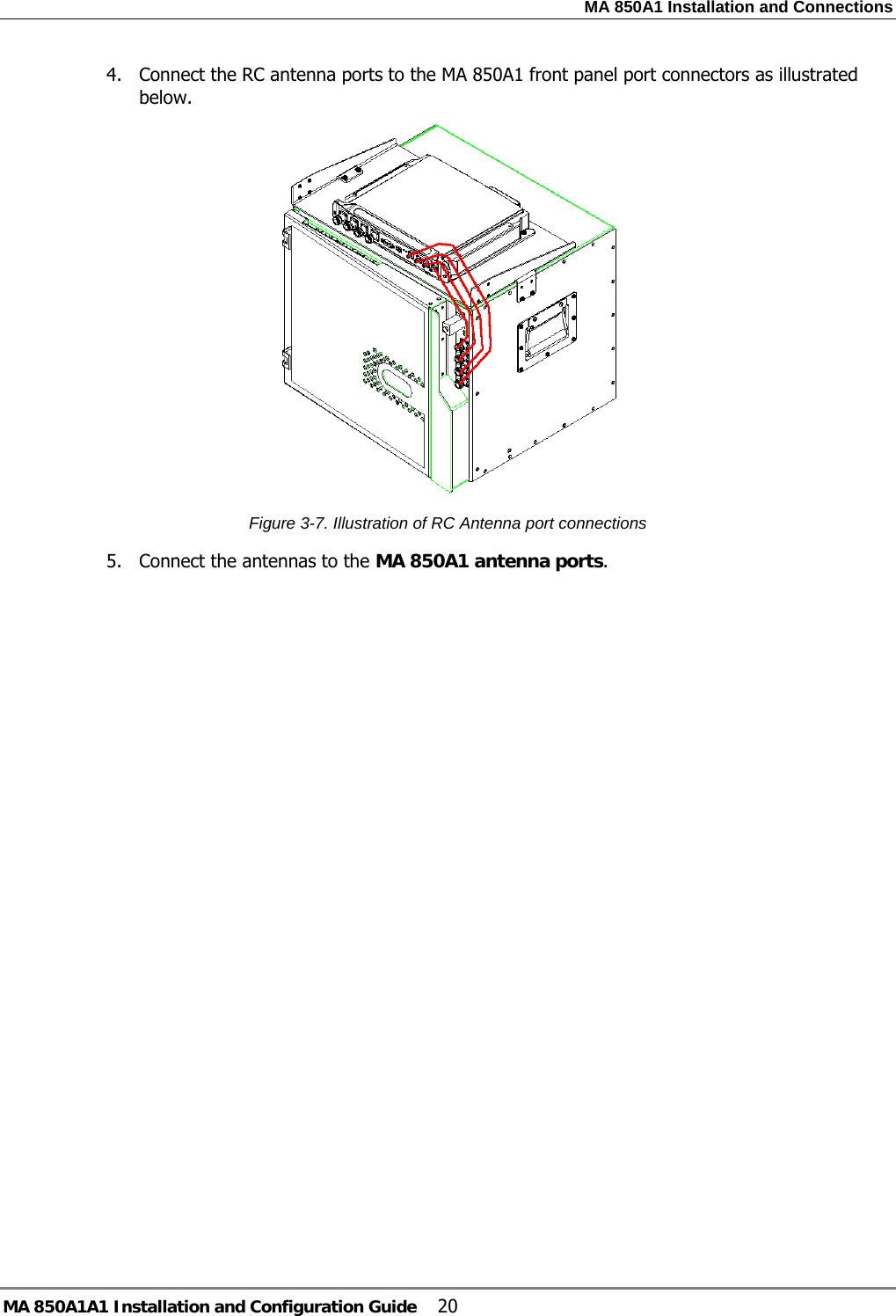
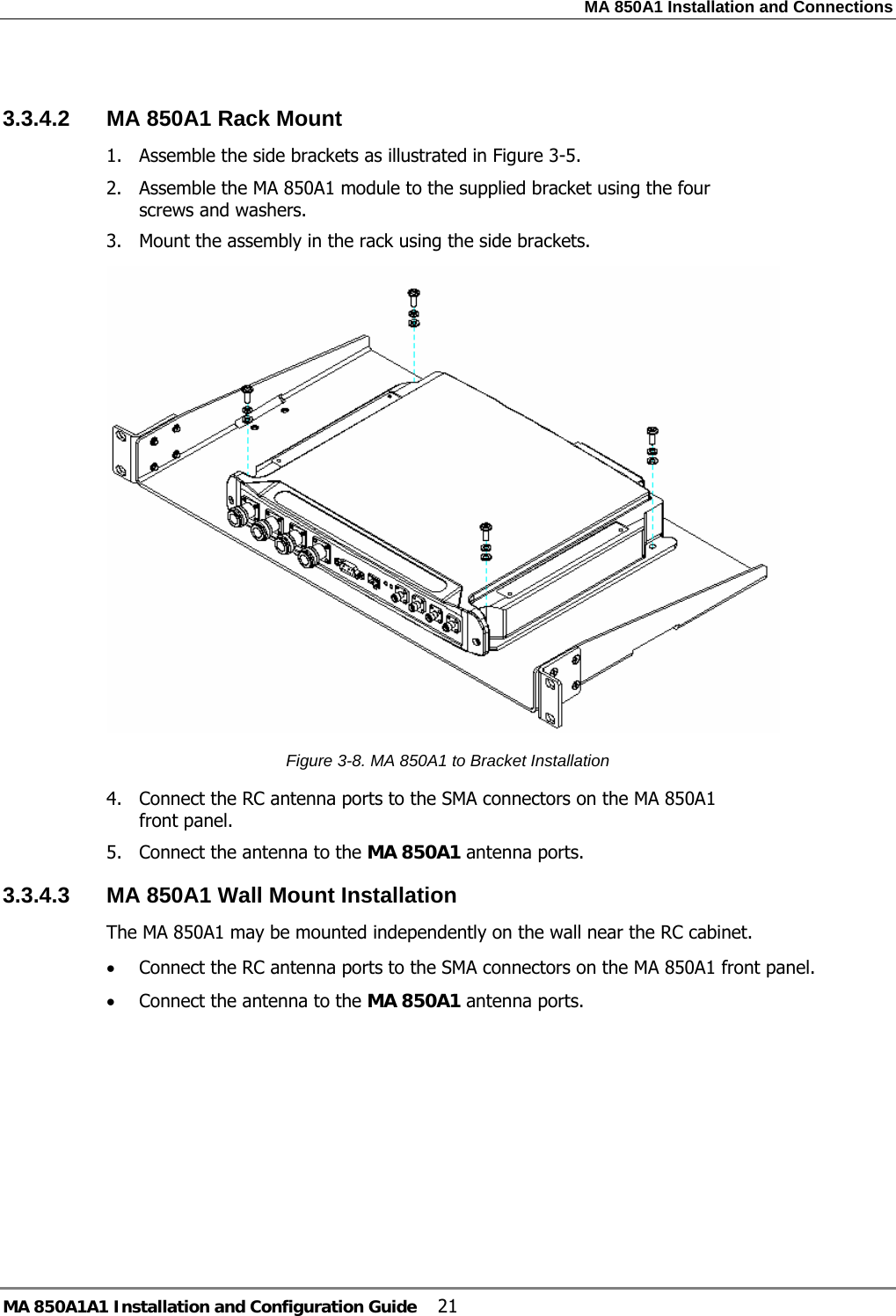
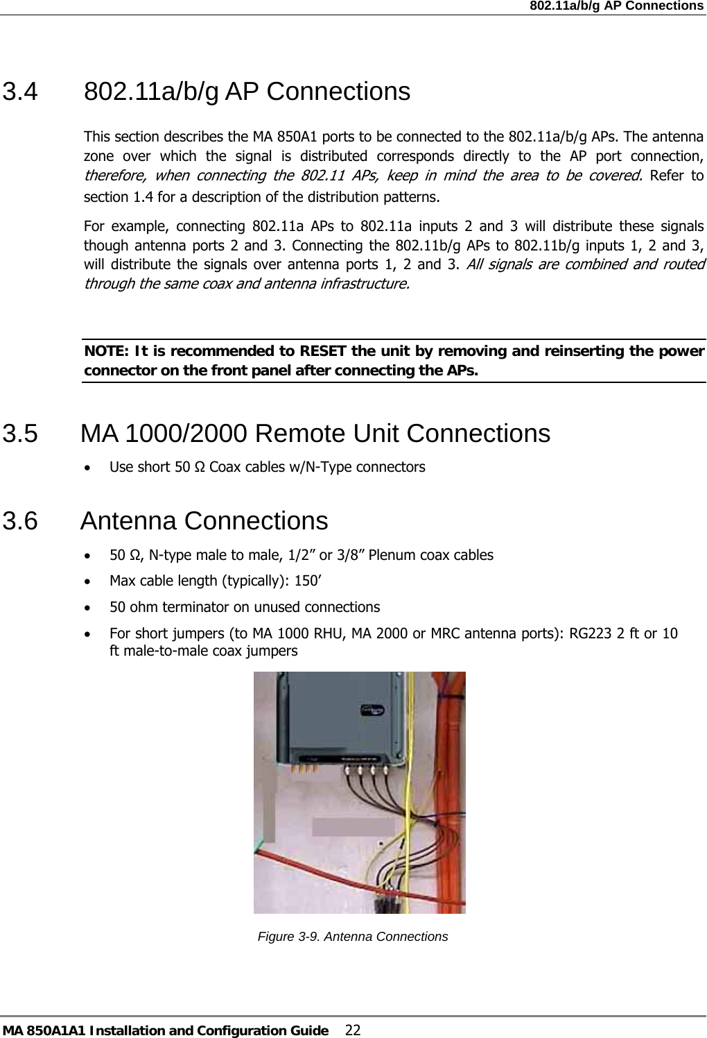
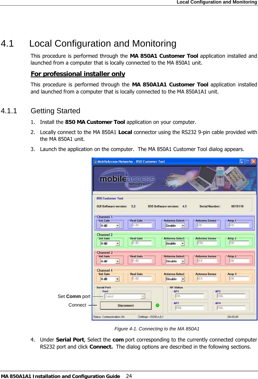
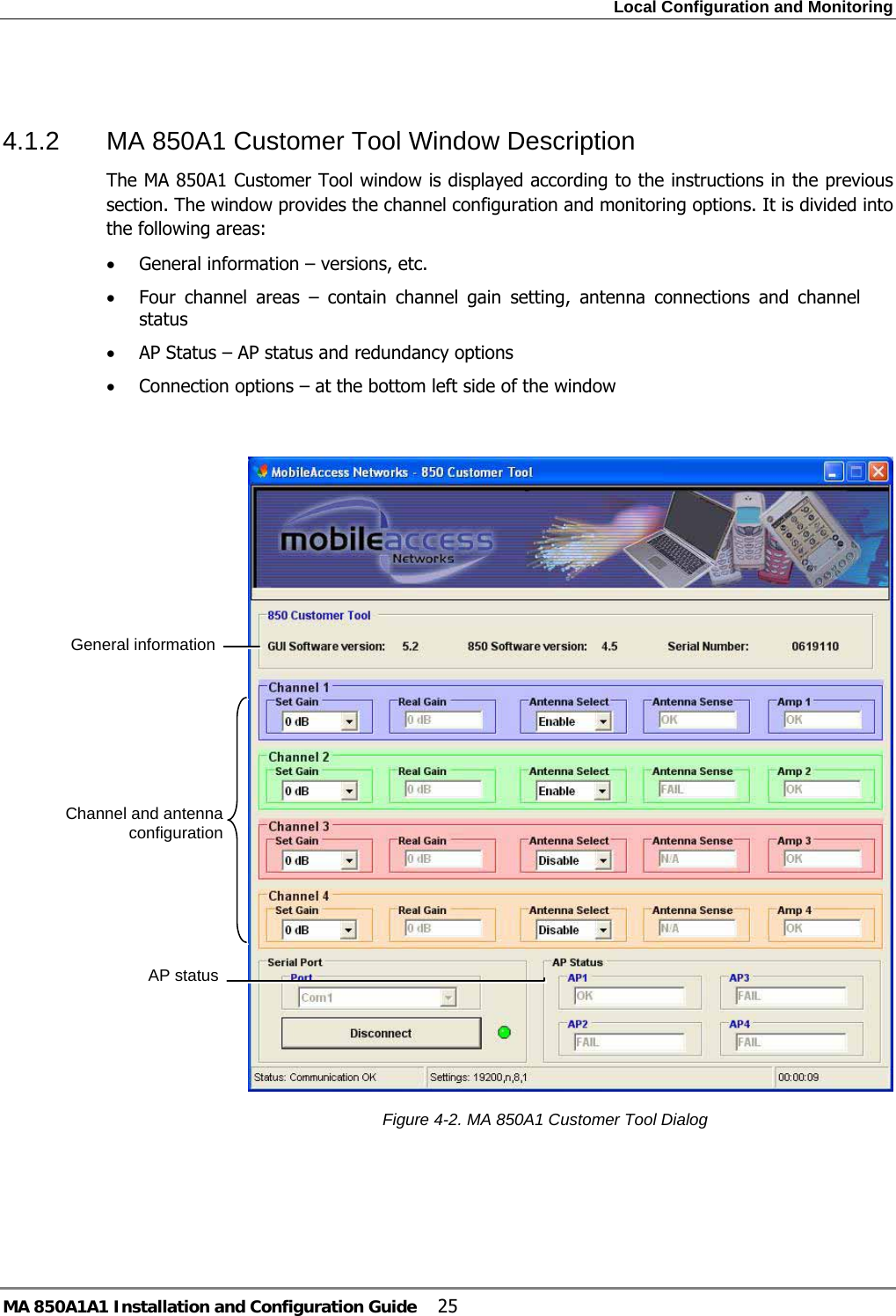
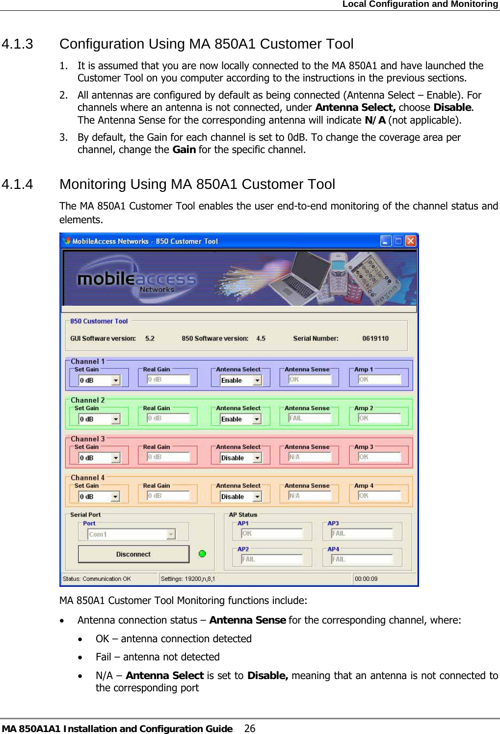
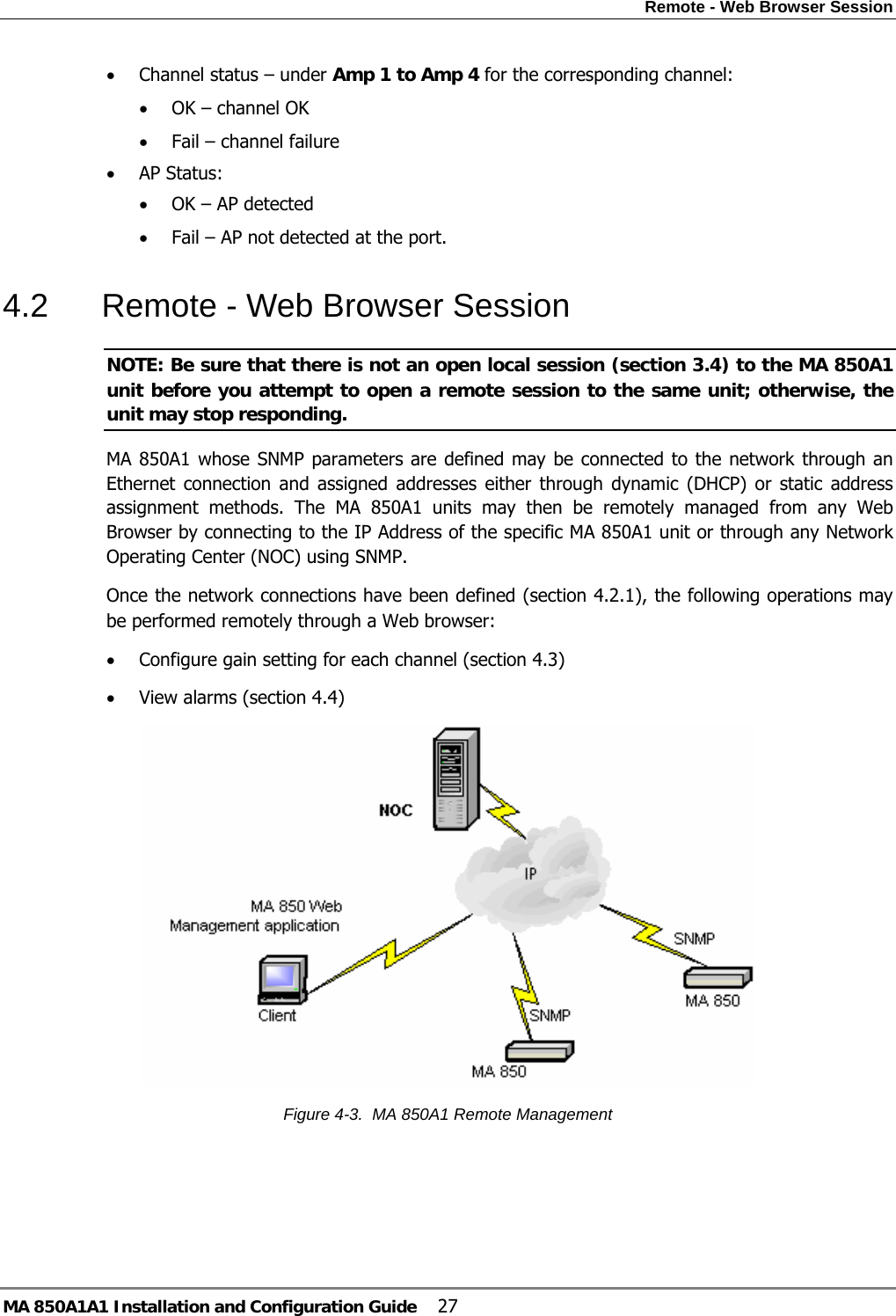
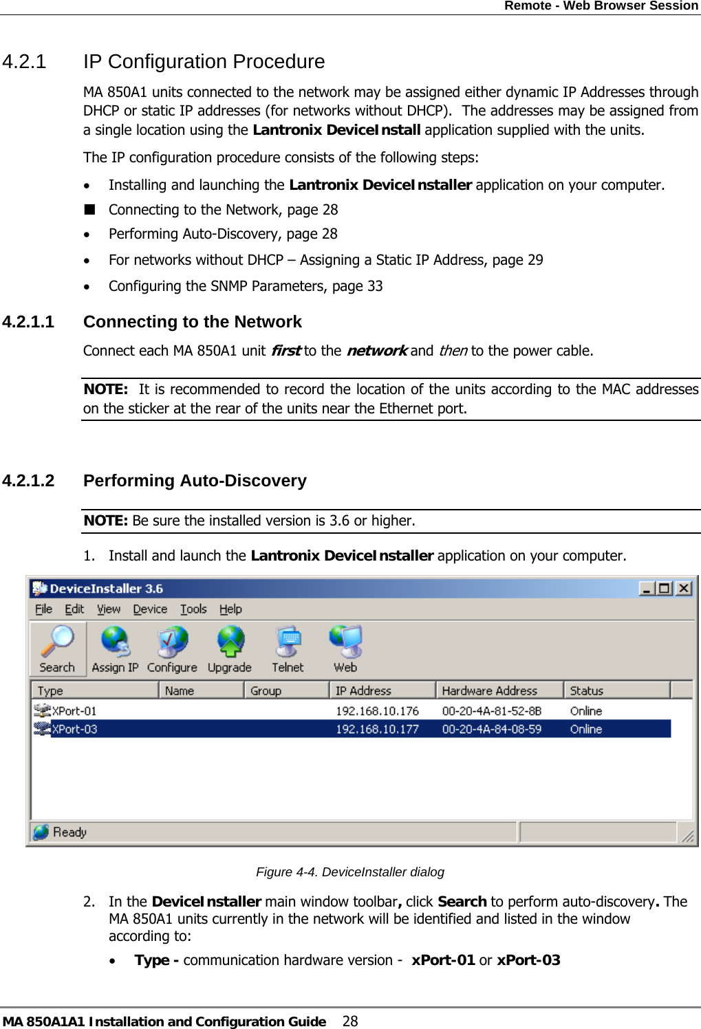
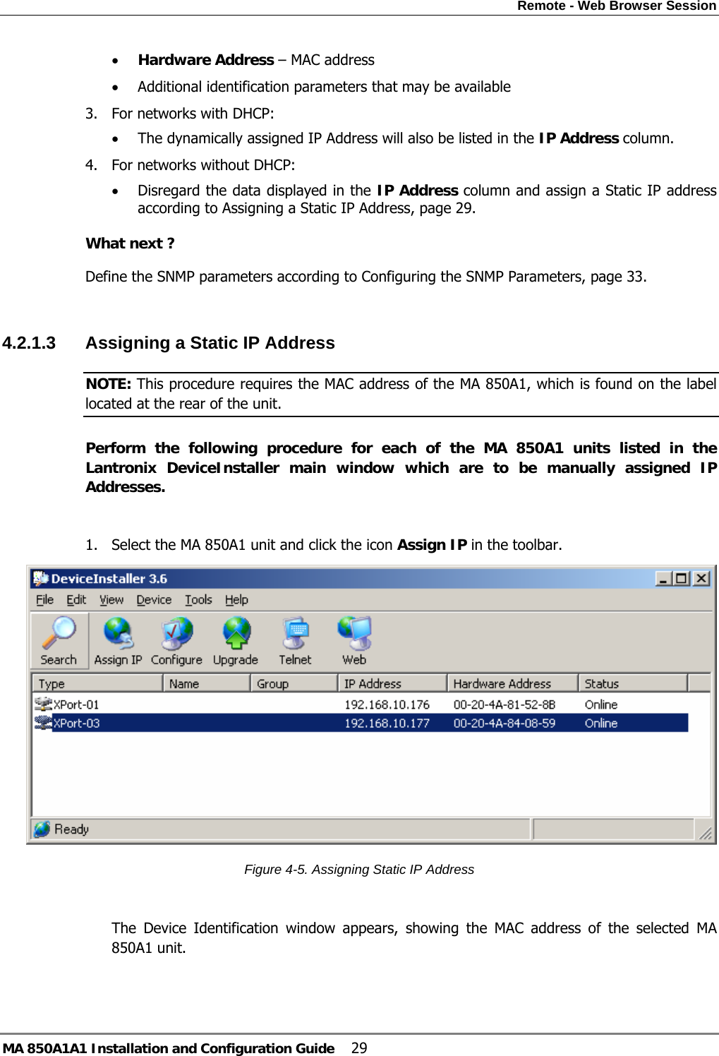
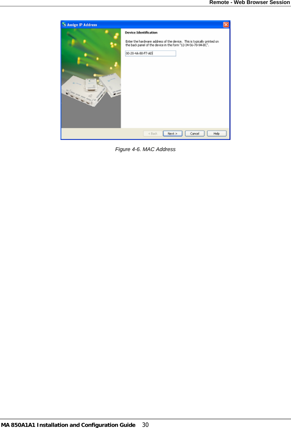
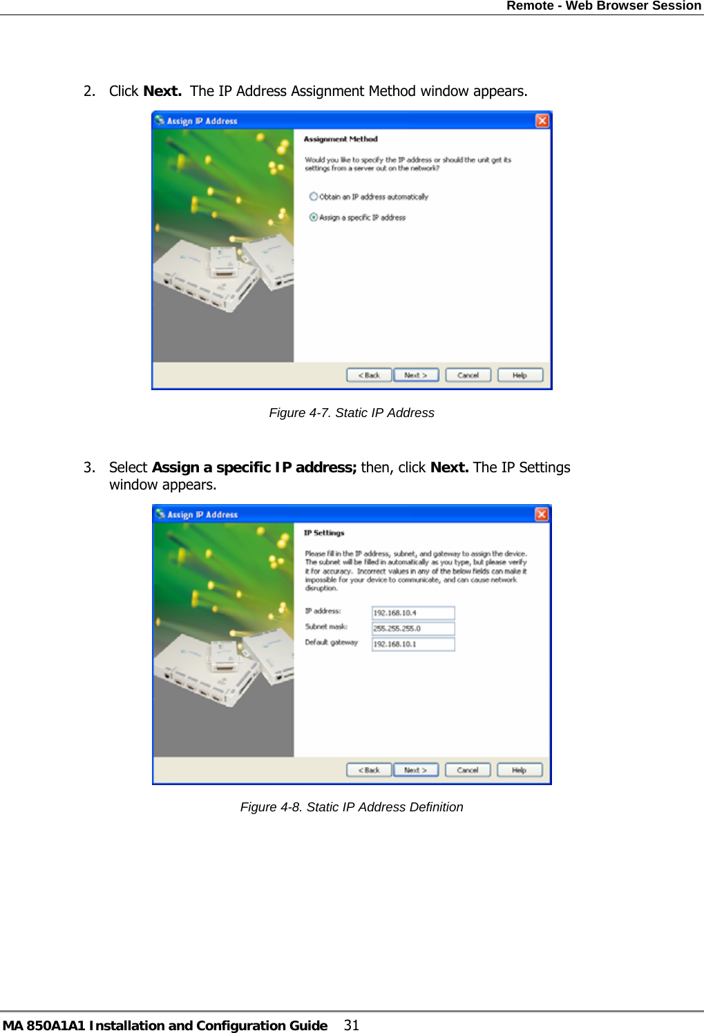
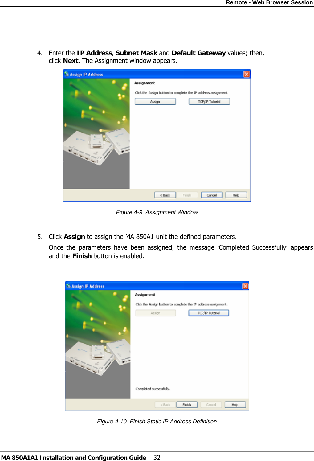
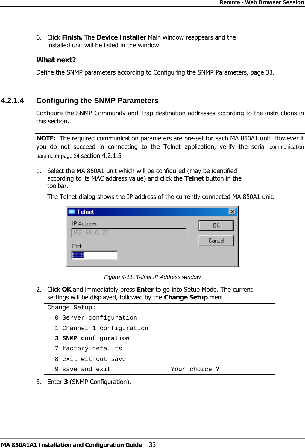
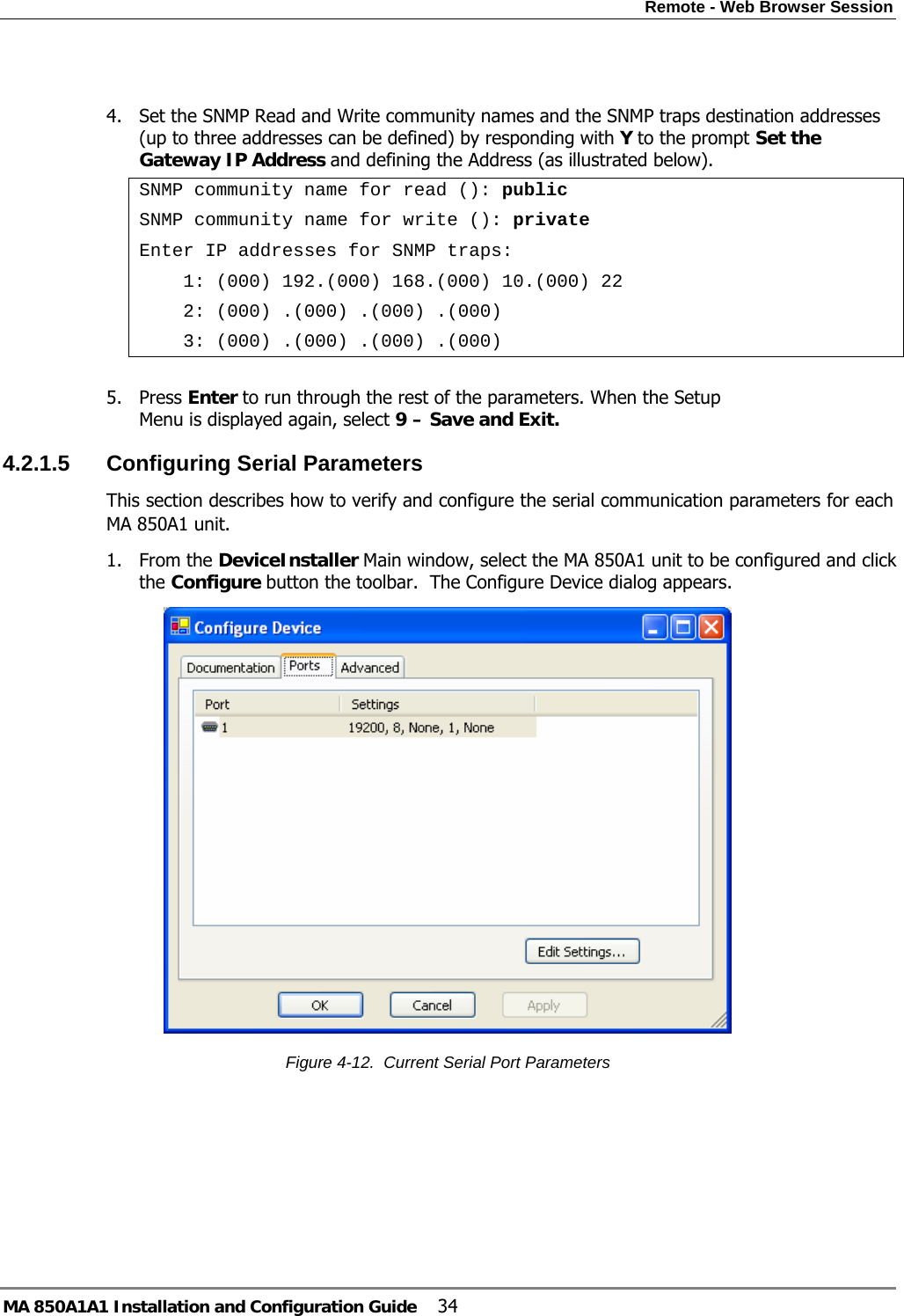
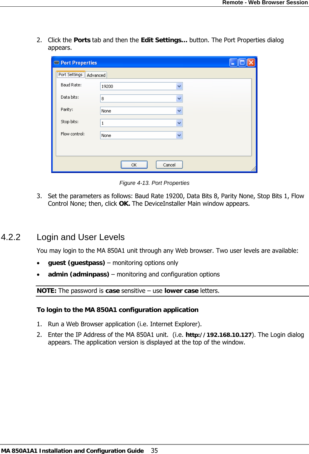
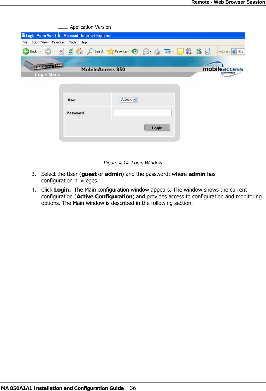
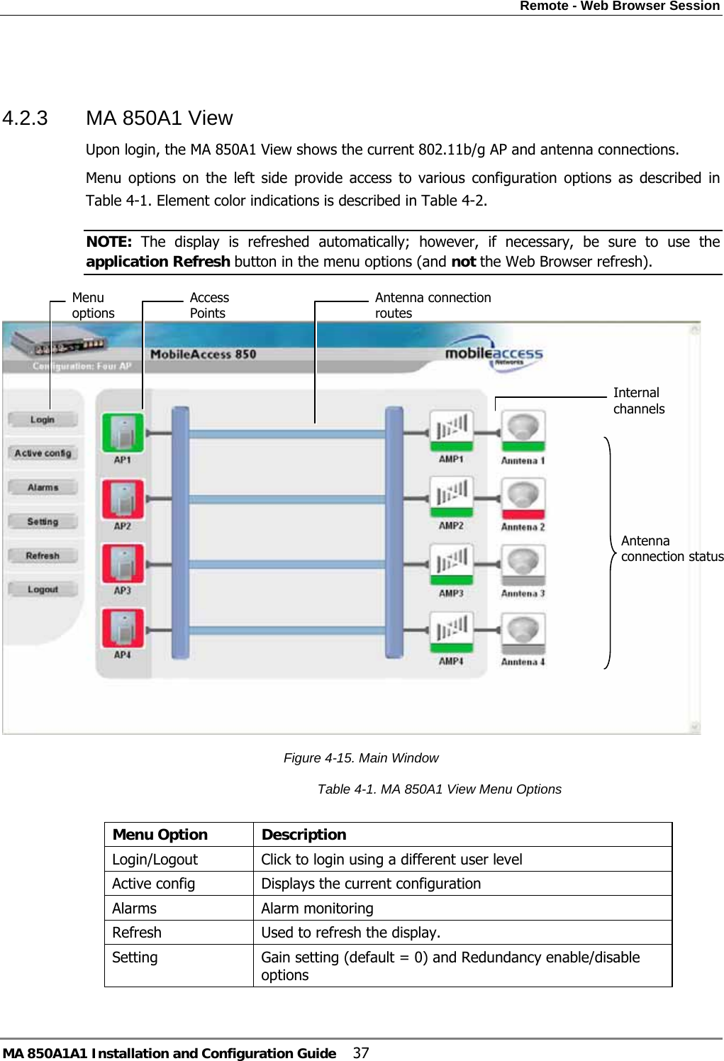
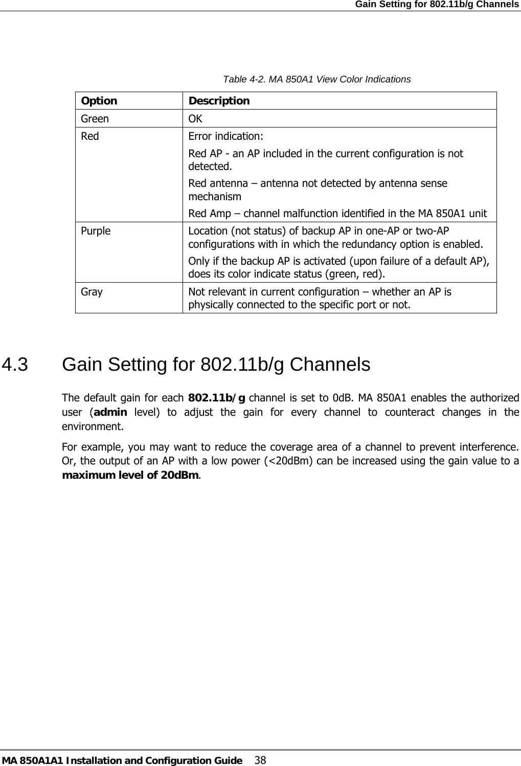
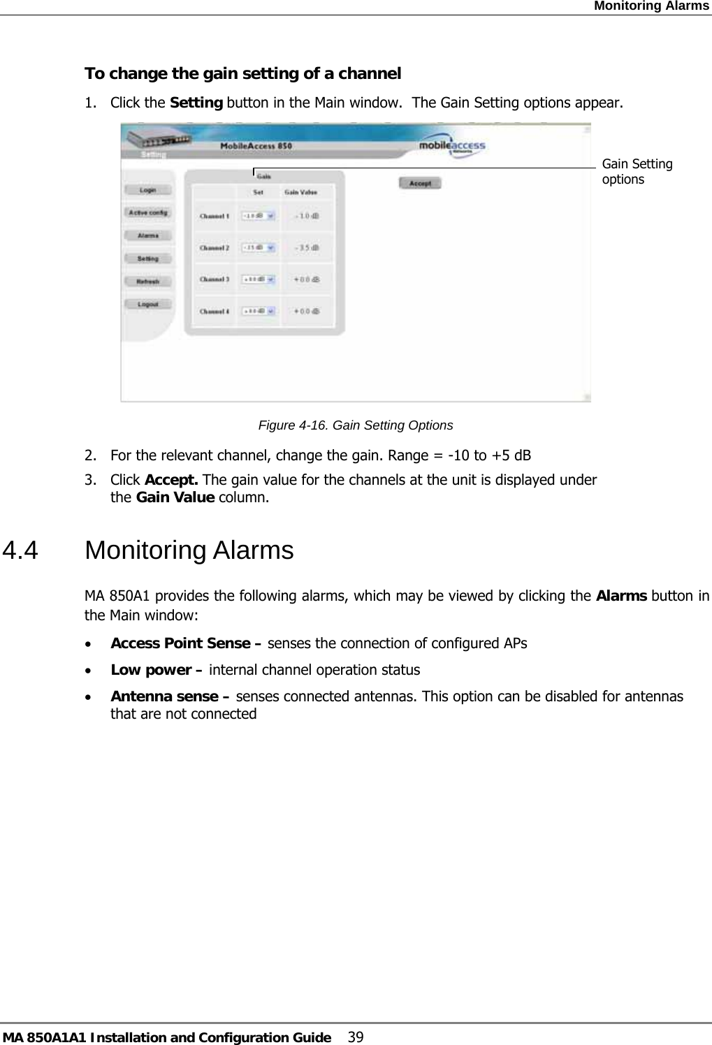
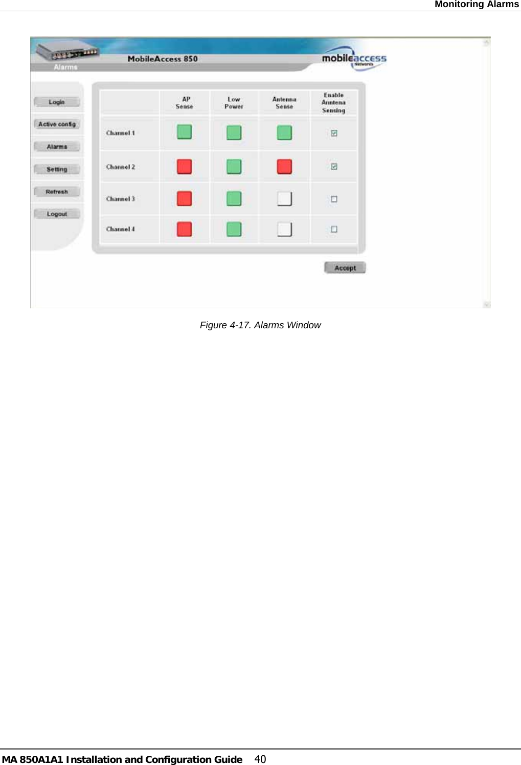
![In-building Antennas MA 850A1A1 Installation and Configuration Guide 12 2.4 In-building Antennas The in-building antennas are connected to the coaxial cable distribution system by jumper cables at various points. The antennas will be mounted on the ceiling tiles and should be exposed. All in-building antenna installations will be such that it will not interfere with indoor traffic and will not enable any person to touch the antennas. • Wideband antennas omni – up to 2.5GHz to support 802.11b/g, up to 6GHz to support 802.11a. Use antennas listed in section 2.4.1 • 50 ohm impedance 2.4.1 Antenna Types These antenna types are to be used with the MA-850A1 device. NOTE: If your installation distributes 802.11b/g only, you may use any of the first three vendor types of listed antennas: Mars Antennas, Cellwave or Antenna Specialists. For 802.11a/b/g service distribution, use antennas from the second table below. Table 2-3. Antennas to be used for 802.11b/g Vendor Catalog number Gain [dBi] Mars Antennas MA-CM36-15 2 low band 3-4 high band 5 WLAN 802.11b Cellwave A08818DC00-28T0 2.1 Antenna Specialists ASP-3561 2 Table 2-4. Antennas to be used for 802.11b/g/a Vendor Catalog number Gain [dBi] Huber+Suhner SWA 0859/360/4/10/V 7 dBi Mars Antennas MA-CP26-2X 2 low band 3-4 high band 6 WLAN 802.11a 2.4.2 Antenna Connections • 50 Ω, 1/2” or 3/8” Plenum coax cables • Max cable length (typically): 150’ • 50 ohm terminator on unused connections • For short jumpers (to MRC antenna ports): RG223 2 ft or 10 ft male-to-male coax jumpers](https://usermanual.wiki/Corning-Optical-Communication/MA850A1/User-Guide-683679-Page-24.png)