Corning Optical Communication MA850A1 In Building RF Distribution System User Manual Revision 1
Corning Optical Communication Wireless In Building RF Distribution System Users Manual Revision 1
Users Manual Revision 1

P/N: 709C00110x
REV: 1.1
Date: July 2006
M
M
Mo
o
ob
b
bi
i
il
l
le
e
eA
A
Ac
c
cc
c
ce
e
es
s
ss
s
s
8
8
85
5
50
0
0A
A
A1
1
1
Installation and Configuration Guide


Preface
Preface Material
MA 850A1A1 Installation and Configuration Guide III
P
Pr
re
ef
fa
ac
ce
e
M
Ma
at
te
er
ri
ia
al
l
© COPYRIGHT 2006, MOBILEACCESS NETWORKS INC. ALL RIGHTS RESERVED.
MOBILEACCESSTM IS A REGISTERED TRADEMARK OF MOBILEACCESS. THIS DOCUMENT CONTAINS OTHER TRADEMARKS, TRADE NAMES AND
SERVICE MARKS OF MOBILEACCESS AND OTHER ORGANIZATIONS, ALL OF WHICH ARE THE PROPERTY OF THEIR RESPECTIVE OWNERS.
THIS DOCUMENT CONTAINS CONFIDENTIAL AND PROPRIETARY INFORMATION OF MOBILEACCESS AND MAY NOT BE COPIED, TRANSMITTED, STORED
IN A RETRIEVAL SYSTEM OR REPRODUCED IN ANY FORMAT OR MEDIA, IN WHOLE OR IN PART, WITHOUT THE PRIOR WRITTEN CONSENT OF
MOBILEACCESS. INFORMATION CONTAINED IN THIS DOCUMENT SUPERSEDES ANY PREVIOUS MANUALS, GUIDES, SPECIFICATIONS, DATA SHEETS OR
OTHER INFORMATION THAT MAY HAVE BEEN PROVIDED OR MADE AVAILABLE TO THE USER.
THIS DOCUMENT IS PROVIDED FOR INFORMATIONAL PURPOSES ONLY, AND MOBILEACCESS DOES NOT WARRANT OR GUARANTEE THE ACCURACY,
ADEQUACY, QUALITY, VALIDITY, COMPLETENESS OR SUITABILITY FOR ANY PURPOSE OF THE INFORMATION CONTAINED IN THIS DOCUMENT.
MOBILEACCESS RESERVES THE RIGHT TO MAKE UPDATES, IMPROVEMENTS AND ENHANCEMENTS TO THIS DOCUMENT AND THE PRODUCTS TO
WHICH IT RELATES AT ANY TIME WITHOUT PRIOR NOTICE TO THE USER. MOBILEACCESS MAKES NO WARRANTIES, EXPRESS OR
IMPLIED, INCLUDING, WITHOUT LIMITATION, THOSE OF MERCHANTABILITY AND FITNESS FOR A PARTICULAR PURPOSE,
WITH RESPECT TO THIS DOCUMENT OR ANY INFORMATION CONTAINED HEREIN.

Preface
Preface Material
MA 850A1A1 Installation and Configuration Guide IV
Policy for Warrantee and Repair
MOBILEACCESS TESTS AND INSPECTS ALL ITS PRODUCTS TO VERIFY THEIR QUALITY AND RELIABILITY. MOBILEACCESS USES EVERY REASONABLE
PRECAUTION TO ENSURE THAT EACH UNIT MEETS THEIR DECLARED SPECIFICATIONS BEFORE SHIPMENT. CUSTOMERS SHOULD ADVISE THEIR
INCOMING INSPECTION, ASSEMBLY, AND TEST PERSONNEL ABOUT THE PRECAUTIONS REQUIRED IN HANDLING AND TESTING OUR PRODUCTS. MANY
OF THESE PRECAUTIONS CAN BE FOUND IN THIS MANUAL.
THE PRODUCTS ARE COVERED BY THE FOLLOWING WARRANTIES:
General Warranty
MOBILEACCESS WARRANTS TO THE ORIGINAL PURCHASER ALL STANDARD PRODUCTS SOLD BY MOBILEACCESS TO BE FREE OF DEFECTS IN
MATERIAL AND WORKMANSHIP FOR ONE (1) YEAR FROM DATE OF SHIPMENT FROM MOBILEACCESS. DURING THE WARRANTY PERIOD,
MOBILEACCESS WILL REPAIR OR REPLACE ANY PRODUCT THAT MOBILEACCESS PROVES TO BE DEFECTIVE. THIS WARRANTY DOES NOT APPLY TO
ANY PRODUCT THAT HAS BEEN SUBJECT TO ALTERATION, ABUSE, IMPROPER INSTALLATION OR APPLICATION, ACCIDENT, ELECTRICAL OR
ENVIRONMENTAL OVER-STRESS, NEGLIGENCE IN USE, STORAGE, TRANSPORTATION OR HANDLING.
Specific Product Warranty Instructions
ALL MOBILEACCESS PRODUCTS ARE WARRANTED AGAINST DEFECTS IN WORKMANSHIP, MATERIALS AND CONSTRUCTION, AND TO NO FURTHER
EXTENT. ANY CLAIM FOR REPAIR OR REPLACEMENT OF UNITS FOUND TO BE DEFECTIVE ON INCOMING INSPECTION BY A CUSTOMER MUST BE MADE
WITHIN 30 DAYS OF RECEIPT OF SHIPMENT, OR WITHIN 30 DAYS OF DISCOVERY OF A DEFECT WITHIN THE WARRANTY PERIOD.
THIS WARRANTY IS THE ONLY WARRANTY MADE BY MOBILEACCESS AND IS IN LIEU OF ALL OTHER WARRANTIES, EXPRESSED OR IMPLIED.
MOBILEACCESS SALES AGENTS OR REPRESENTATIVES ARE NOT AUTHORIZED TO MAKE COMMITMENTS ON WARRANTY RETURNS.
Returns
IN THE EVENT THAT IT IS NECESSARY TO RETURN ANY PRODUCT AGAINST ABOVE WARRANTY, THE FOLLOWING PROCEDURE SHALL BE FOLLOWED:
1. RETURN AUTHORIZATION IS TO BE RECEIVED FROM MOBILEACCESS PRIOR TO RETURNING ANY UNIT. ADVISE MOBILEACCESS OF THE MODEL,
SERIAL NUMBER, AND DISCREPANCY. THE UNIT MAY THEN BE FORWARDED TO MOBILEACCESS, TRANSPORTATION PREPAID. DEVICES RETURNED
COLLECT OR WITHOUT AUTHORIZATION MAY NOT BE ACCEPTED.
2. PRIOR TO REPAIR, MOBILEACCESS WILL ADVISE THE CUSTOMER OF OUR TEST RESULTS AND ANY CHARGES FOR REPAIRING CUSTOMER-CAUSED
PROBLEMS OR OUT-OF-WARRANTY CONDITIONS ETC.
3. REPAIRED PRODUCTS ARE WARRANTED FOR THE BALANCE OF THE ORIGINAL WARRANTY PERIOD, OR AT LEAST 90 DAYS FROM DATE OF
SHIPMENT.
Limitations of Liabilities
MOBILEACCESS'S LIABILITY ON ANY CLAIM, OF ANY KIND, INCLUDING NEGLIGENCE FOR ANY LOSS OR DAMAGE ARISING FROM, CONNECTED WITH,
OR RESULTING FROM THE PURCHASE ORDER, CONTRACT, QUOTATION, OR FROM THE PERFORMANCE OR BREACH THEREOF, OR FROM THE DESIGN,
MANUFACTURE, SALE, DELIVERY, INSTALLATION, INSPECTION, OPERATION OR USE OF ANY EQUIPMENT COVERED BY OR FURNISHED UNDER THIS
CONTACT, SHALL IN NO CASE EXCEED THE PURCHASE PRICE OF THE DEVICE WHICH GIVES RISE TO THE CLAIM.
EXCEPT AS EXPRESSLY PROVIDED HEREIN, MOBILEACCESS MAKES NO WARRANTY, EXPRESSED OR IMPLIED, WITH
RESPECT TO ANY GOODS, PARTS AND SERVICES PROVIDED IN CONNECTION WITH THIS AGREEMENT INCLUDING, BUT NOT
LIMITED TO, THE IMPLIED WARRANTIES OF MERCHANTABILITY AND FITNESS FOR A PARTICULAR PURPOSE. MOBILEACCESS
SHALL NOT BE LIABLE FOR ANY OTHER DAMAGE INCLUDING, BUT NOT LIMITED TO, INDIRECT, SPECIAL OR CONSEQUENTIAL
DAMAGES ARISING OUT OF OR IN CONNECTION WITH FURNISHING OF GOODS, PARTS AND SERVICE HEREUNDER, OR THE
PERFORMANCE, USE OF, OR INABILITY TO USE THE GOODS, PARTS AND SERVICE.
Preface
Preface Material
MA 850A1A1 Installation and Configuration Guide V
Reporting Defects
THE UNITS WERE INSPECTED BEFORE SHIPMENT AND FOUND TO BE FREE OF MECHANICAL AND ELECTRICAL DEFECTS.
EXAMINE THE UNITS FOR ANY DAMAGE THAT MAY HAVE BEEN CAUSED IN TRANSIT. IF DAMAGE IS DISCOVERED, FILE A CLAIM WITH THE FREIGHT
CARRIER IMMEDIATELY. NOTIFY MOBILEACCESS AS SOON AS POSSIBLE.
NOTE: KEEP ALL PACKING MATERIAL UNTIL YOU HAVE COMPLETED THE INSPECTION
WARNING: TO COMPLY WITH FCC RF EXPOSURE COMPLIANCE REQUIREMENTS, ANTENNAS USED FOR THIS PRODUCT MUST BE FIXED MOUNTED
ON INDOOR PERMANENT STRUCTURES, PROVIDING A SEPARATION DISTANCE OF AT LEAST 20 CM FROM ALL PERSONS DURING NORMAL OPERATION.
WARNING: ANTENNA GAIN SHOULD NOT EXCEED 10dBi .
WARNING: EACH INDIVIDUAL ANTENNA USED FOR THIS TRANSMITTER MUST BE INSTALLED TO PROVIDE A MINIMUM SEPARATION DISTANCE OF 20
CM OR MORE FROM ALL PERSONS AND MUST NOT BE CO-LOCATED WITH ANY OTHER ANTENNA FOR MEETING RF EXPOSURE REQUIREMENTS.
WARNING: THE DESIGN OF THE ANTENNA INSTALLATION NEEDS TO BE IMPLEMENTED IN SUCH A WAY SO AS TO ENSURE RF RADIATION SAFETY
LEVELS AND NON-ENVIRONMENTAL POLLUTION DURING OPERATION.
ATTENTION:
COMPLIANCE WITH RF SAFETY REQUIREMENTS:
MOBILEACCESS™ PRODUCTS HAVE NO INHERENT SIGNIFICANT RF RADIATION.
THE RF LEVEL ON THE DOWN LINK IS VERY LOW AT THE DOWNLINK PORTS. THEREFORE, THERE IS NO DANGEROUS RF RADIATION WHEN THE
ANTENNA IS NOT CONNECTED.
Safety
WARNING! To comply with FCC RF exposure compliance requirements, antennas used for this product
must be fixed mounted on indoor permanent structures, providing a separation distance of at least
20 cm from all persons during normal operation.
1. Each individual antenna used for this transmitter must be installed to
provide a minimum separation distance of 20 cm or more from all persons
and must not be co-located with any other antenna for meeting RF
exposure requirements.
2. The design of the antenna installation needs to be implemented in such a
way so as to ensure RF radiation safety levels and non-environmental
pollution during operation.
Compliance with RF safety requirements:
• MobileAccess™ products have no inherent significant RF radiation.
• The RF level on the downlink is very low at the downlink ports. Therefore, there is no
dangerous RF radiation when the antenna is not connected.
Preface
Preface Material
MA 850A1A1 Installation and Configuration Guide VI
Certification
MobileAccess products have met the approvals of the following certifying organizations:
ISO 9001:2000 (from March 15, 2004)
FCC Certification
For US: FCC 47 CFT part 15 for 802.11b/g
Per section 15.204B.
ID:OJFMA850 will only be supplied as complete system per section 15.204(b) of rules.
FCC certification for MA 850A1 is valid for use only with the following elements:
Antenna types: section 2.4.1 in this User Guide
AP Types: section 2.5 in the User Guide
NOTE: This equipment has been tested and found to comply with the limits for a Class B digital
device, pursuant to Part 15 of the FCC Rules. These limits are designed to provide reasonable
protection against harmful interference in a residential installation. This equipment generates,
uses and can radiate radio frequency energy and, if not installed and used in accordance with
the instructions, may cause harmful interference to radio communications. However, there is no
guarantee that interference will not occur in a particular installation. If this equipment does
cause harmful interference to radio or television reception, which can be determined by turning
the equipment off and on, the user is encouraged to try to correct the interference by one or
more of the following measures:
• Reorient or relocate the receiving antenna.
• Increase the separation between the equipment and receiver.
• Connect the equipment into an outlet on a circuit different from that to which the receiver is
connected.
• Consult the dealer or an experienced radio/TV technician for help.
WARNING! Changes or modifications to this equipment not expressly approved by the party responsible
for compliance MobileAcess Ltd. could void the user’s authority to operate the equipment.

Preface
Preface Material
MA 850A1A1 Installation and Configuration Guide VII
Professional Installation of Transmitter
According to FCC 15.203, if an intentional radiator has a standard antenna connector, it must be
professionally installed according to FCC 15.203 regulations:
1. The MA850A1 cannot be sold to the general public. Only professional installer, qualified ("licensed")
by MobileAccess for this purpose is aloud to install the MA850A1.
2. The installation must be controlled and follow the requirement of "Installation Manual"
(P/N:709C001103). Each potential installer must receive special training, which is a condition for
receiving the license from MobileAccess Inc to become a "licensed" installer. The installation
procedure as described in the "Installation Manual" includes the mechanical installation and initial
setup by a PC based tool.
3. The intended application of the system is exclusively for the commercial/industry use.

Preface
Preface Material
MA 850A1A1 Installation and Configuration Guide VIII
About This Guide
This user guide provides all the information necessary to install and configure the MobileAccess
850A1 units.
Revision History
The revision history for this document is shown in Table
1-1.
Table
1-1: Revision history
Version Date Description
1.0 JULY-06 Initial version
1.1 JULY-06 Section 2.4.1 – added comment that the antenna
types are to be used with the MA 850A1A1 device.

Preface
Preface Material
MA 850A1A1 Installation and Configuration Guide IX
List of Acronyms
AGC Automatic Gain Control
BDA Bi-Directional Amplifier
BU Base Unit
DL Downlink
RHU Remote Hub Unit
SNR Signal to Noise Ratio
UL Uplink
VDC Volts Direct Current
AP Access Point

Preface
Preface Material
MA 850A1A1 Installation and Configuration Guide X
Table of Contents
Preface Material .........................................................................................................................III
Policy for Warrantee and Repair .......................................................................................................IV
Certification....................................................................................................................................VI
Professional Installation of Transmitter ............................................................................................VII
About This Guide ......................................................................................................................... VIII
Revision History ........................................................................................................................... VIII
List of Acronyms .............................................................................................................................IX
Table of Contents ............................................................................................................................ X
Introduction to the MA 850A1 System .....................................................................................1
1.1 About MobileAccess MA 850A1 ................................................................................................... 1
1.1.1 MA 850A1 Features and Capabilities .................................................................................. 2
1.2 Unit Architecture....................................................................................................................... 3
1.3 Installation Configurations ......................................................................................................... 3
1.3.1 Standalone...................................................................................................................... 4
1.3.2 Add-On to MA 1000 RHU .................................................................................................. 4
1.3.3 Add-on to MA 2000 System .............................................................................................. 4
1.4 Signal Distribution in the MA 850A1 ............................................................................................ 5
1.5 Commissioning and Monitoring................................................................................................... 7
1.6 MA 850A1 Connections, LEDs and Ports ...................................................................................... 7
1.6.1 Front Panel Port Connections and LEDs ............................................................................. 7
1.6.2 Rear Panel Port Connections and LEDs .............................................................................. 8
Infrastructure Preparation.........................................................................................................9
2.1 Installation Requirements .......................................................................................................... 9
2.2 Coaxial Cable Connections .......................................................................................................10
2.2.1 General Cable Installation Procedures.............................................................................. 10
2.2.2 RF Rules ....................................................................................................................... 10
2.3 Power Consumption, Connections and Power Supplies................................................................ 11
2.3.1 Power Safety Instructions............................................................................................... 11
2.3.2 MA 850A1 Power Consumption ....................................................................................... 11
2.3.3 Types of Power Supplies................................................................................................. 11

Preface
Preface Material
MA 850A1A1 Installation and Configuration Guide XI
2.3.4 Power Connections ........................................................................................................ 11
2.4 In-building Antennas ............................................................................................................... 12
2.4.1 Antenna Types .............................................................................................................. 12
2.4.2 Antenna Connections ..................................................................................................... 12
2.5 Access Points.......................................................................................................................... 13
Installation................................................................................................................................14
3.1 Accessory Kits......................................................................................................................... 14
3.2 Positioning the Unit ................................................................................................................. 14
3.3 MA 850A1 Installation and Connections..................................................................................... 15
3.3.1 Wall Mount Standalone................................................................................................... 15
3.3.2 Mounted onto MA 1000 .................................................................................................. 16
3.3.3 Mounted onto an MA 1200 / MA 1000 Installation............................................................. 17
3.3.4 Add-on to a MA 2000 System.......................................................................................... 18
3.3.4.1 MA 850A1 RC 2000 Assembly.............................................................................. 19
3.3.4.2 MA 850A1 Rack Mount ....................................................................................... 21
3.3.4.3 MA 850A1 Wall Mount Installation ....................................................................... 21
3.4 802.11a/b/g AP Connections .................................................................................................... 22
3.5 MA 1000/2000 Remote Unit Connections................................................................................... 22
3.6 Antenna Connections............................................................................................................... 22
Configuration and Management.............................................................................................23
4.1 Local Configuration and Monitoring........................................................................................... 24
4.1.1 Getting Started.............................................................................................................. 24
4.1.2 MA 850A1 Customer Tool Window Description.................................................................. 25
4.1.3 Configuration Using MA 850A1 Customer Tool.................................................................. 26
4.1.4 Monitoring Using MA 850A1 Customer Tool...................................................................... 26
4.2 Remote - Web Browser Session................................................................................................ 27
4.2.1 IP Configuration Procedure............................................................................................. 28
4.2.1.1 Connecting to the Network ................................................................................. 28
4.2.1.2 Performing Auto-Discovery ................................................................................. 28
4.2.1.3 Assigning a Static IP Address .............................................................................. 29
4.2.1.4 Configuring the SNMP Parameters ....................................................................... 33
4.2.1.5 Configuring Serial Parameters ............................................................................. 34
4.2.2 Login and User Levels .................................................................................................... 35
4.2.3 MA 850A1 View ............................................................................................................. 37
4.3 Gain Setting for 802.11b/g Channels......................................................................................... 38
4.4 Monitoring Alarms................................................................................................................... 39

Preface
Preface Material
MA 850A1A1 Installation and Configuration Guide XII
SNMP Management Using Any Standard SNMP Manager ...................................................41
5.1 Traps List ............................................................................................................................... 41
MA 850A1A1 Installation and Configuration Guide 1
1
I
In
nt
tr
ro
od
du
uc
ct
ti
io
on
n
t
to
o
t
th
he
e
M
MA
A
8
85
50
0A
A1
1
S
Sy
ys
st
te
em
m
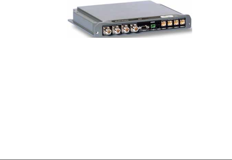
1.1 About MobileAccess MA 850A1
Figure 1-1. MobileAccess 850
The MA-850 Wi-Fi Module enables 802.11b/g and 802.11a Wi-Fi signals to be combined with
other wireless services for simultaneous distribution over the MobileAccess Universal Wireless
Network.
The MA-850 can be deployed in a stand-alone mode for Wi-Fi only environments, or it can be
connected to other MobileAccess elements (MA-1000/2000) to deliver Wi-Fi along with other
wireless services including cellular/PCS, public safety, and WMTS.
Unlike traditional Wi-Fi deployments, where 802.11 Access Points (APs) are installed on ceilings
and walls throughout the facility, the MA-850 enables organizations to cluster their 802.11 APs
together in secure telecom closets.
With the clustering approach, IT managers can more easily access APs, which ultimately reduces
the operational costs of managing the Wi-Fi network and minimizes disruption within the facility.

About MobileAccess MA 850A1
MA 850A1A1 Installation and Configuration Guide 2
1.1.1 MA 850A1 Features and Capabilities
• Multi-use infrastructure:
The same cables and antennas used for Wi-Fi can be used to support the simultaneous
extension and distribution of other wireless voice and data services, as follows:
o Data services from four 802.11b/g APs and 802.11a APs
o Mobile services from MobileAccess 1000/2000, ModuLite or Litenna remote units
• Simple installation and maintenance:
o All active elements are in the telecom shaft or closet
o All data and voice services distributed via a common coax cabling and broadband
antennas
o AP Clustering - 802.11 access points (APs) connect to the MA-850 in telecom closets
• Management:
o Robust system management - Familiar SNMP-based management provides proactive
visibility and control of the MA-850 based Wi-Fi infrastructure.
o Management through local RS232 connection and remote WEB management
• WI-Fi applications transparency - The MA-850 uses discrete, passive antennas to
radiate 802.11 signals, providing a coverage architecture that replicates the behaviors
necessary to transparently support advanced AP features and location-sensitive Wi-Fi
applications.
• High-power - With integral constant gain amplifiers combined with its low-loss
architecture, the MA-850 offers scalable support for demanding applications such as wireless
VoIP and 802.11a.
Unit Architecture
MA 850A1A1 Installation and Configuration Guide 3
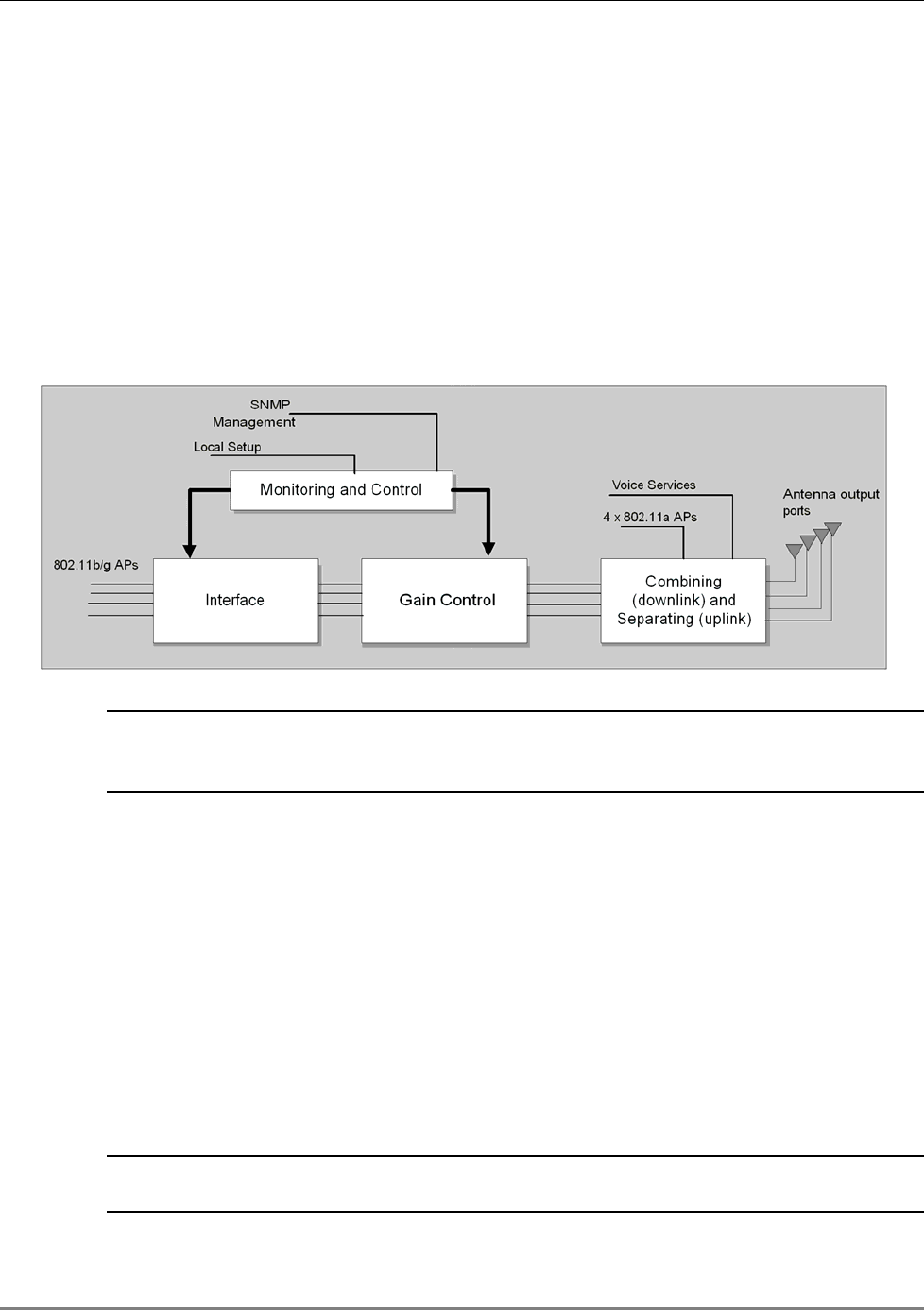
1.2 Unit Architecture
MA 850A1 consists of the following main
functional
modules:
• Interface: Provides interface to the 802.11b/g AP ports.
• Gain control mechanism: Gain control to adjust 802.11b/g signals to specific site
• Combining and separating mechanism: On the downlink, combines the amplified
802.11b/g signals with the 802.11a AP signals and those of mobile services. On the
uplink, separates the signals and routes them to the corresponding ports.
• Monitoring and control: Support for WEB monitoring, SNMP MIBs displayed via a
standard Web browser and local RS232 and service options.
Figure 1-2. MobileAccess 850 Functional Block Diagram
NOTE: If the MobileAccess 850 is operated without cellular service, it is required to connect
50Ω termination points to each of the remote connectors in the unit. A 50 Ω termination is
also required on each unused AP port.
1.3 Installation Configurations
The MA 850A1 can be installed as a standalone unit or integrated with MA 1000/2000 systems
and its signals converged with the mobile services to be distributed through the MA 850A1
antenna connections.
MA 850A1 can be installed in the following configurations:
• Standalone – to provide coverage only for 802.11a/b/g services
• Add-on to a MobileAccess 1000 series RHU (with and without MA 1200 add-on)
• Add-on to MobileAccess 2000 system
NOTE: In all installation types, all the signals are converged via the MA 850A1 and distributed
via the antennas connected to the MA 850A1 antenna ports.
Installation Configurations
MA 850A1A1 Installation and Configuration Guide 4
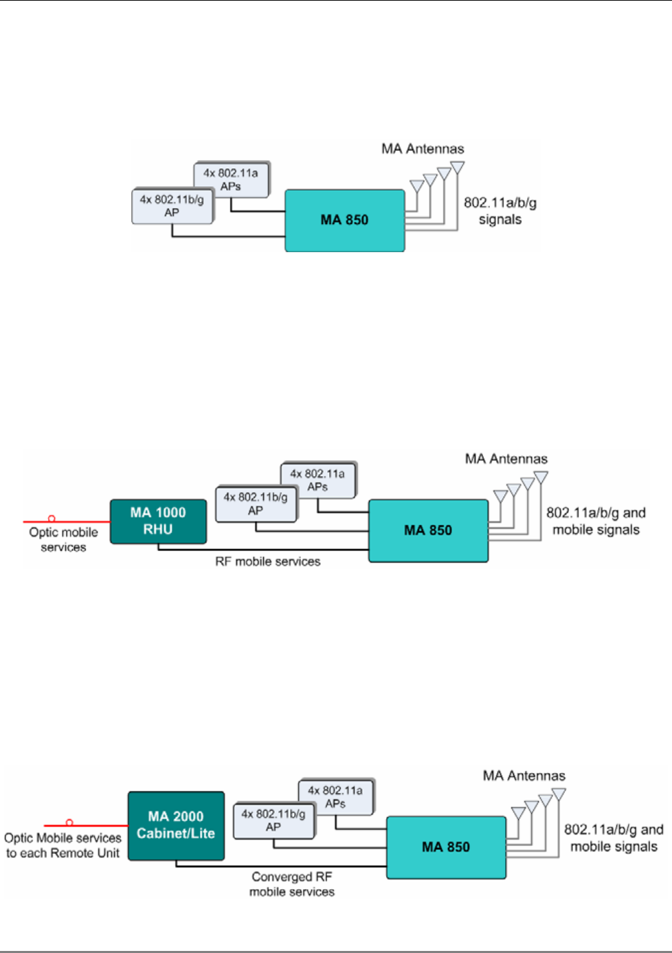
1.3.1 Standalone
The standalone installation configuration provides coverage for 802.11a/b/g services only and
distributes the signals over the antennas.
Figure 1-3. MA 850A1 Standalone Installation Configuration
1.3.2 Add-On to MA 1000 RHU
The MA 850A1 can be installed as an add-on unit to a MA 1000 RHU. In this type of installation,
the MA 1000 RHU services are routed to the MA 850A1 inputs where they are integrated with
the MA 850A1 Wi-Fi data services and, through the MA 850A1 antenna connections, distributed
through the same coax broadband antenna infrastructure. The following figure shows the
architecture.
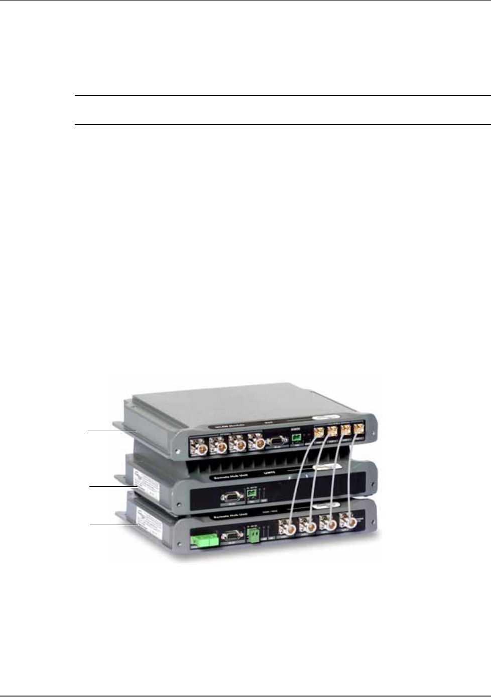
Figure 1-4 MA 850A1 as Add-On to MA 1000 System
1.3.3 Add-on to MA 2000 System
The MA 850A1 can be installed as an (external) add-on unit to the MA 2000 system. In this type
of installation, the combined MA 2000 services are routed to the MA 850A1 inputs where they
are integrated with the MA 850A1 Wi-Fi data services and, through the MA 850A1 antenna
connections, distributed through the same coax broadband antenna infrastructure. The
following figure shows the architecture.
Signal Distribution in the MA 850A1
MA 850A1A1 Installation and Configuration Guide 5
Figure 1-5. MA 850A1 Add-On to MA 2000 System
1.4 Signal Distribution in the MA 850A1
The MA 850A1 distributes the 802.11a/b/g signals from each AP port to the corresponding
antenna port and mobile services (where MA 1000/2000 systems are integrated with the MA
850A1), over all connected antennas. For example, the signals from an AP connected to 802.11
port-2, is routed to antenna port-2; signals from an AP connected to 802.11b/g port-4, is routed
to antenna 4, etc.
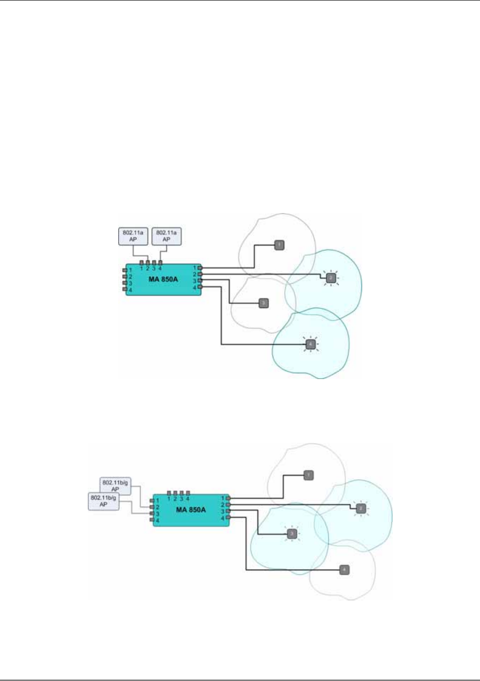
The following figure shows an 802.11a distribution example. Signals of AP connected to 802.11a
ports 2 and 4 are routed to the corresponding antenna ports (2 and 4). Areas covered by
antennas 1 and 3 do not receive 802.11a signals.
Figure 1-6. Example of 802.11a Signal Distribution
The following figure shows an 802.11b/g distribution example. Signals of AP connected to
802.11b/g ports 2 and 3 are routed to the corresponding antenna ports (2 and 3).
Figure 1-7. Example of 802.11b/g Signal Distribution
Signal Distribution in the MA 850A1
MA 850A1A1 Installation and Configuration Guide 6
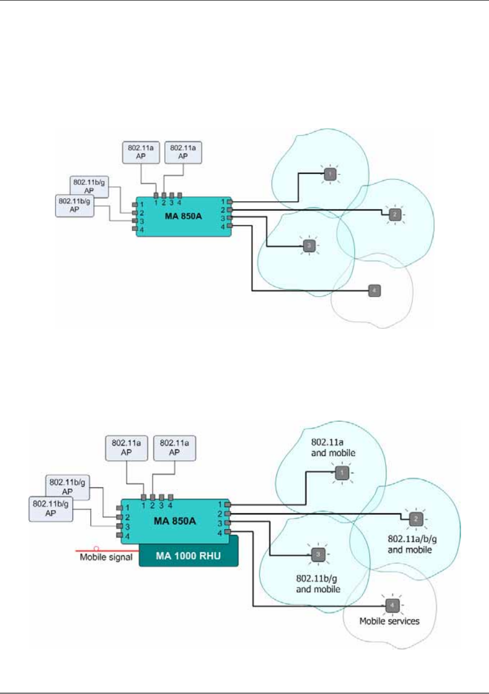
The following figure shows an 802.11a/b/g distribution example. Signals of AP connected to
802.11a ports 1 and 2 are routed to the corresponding antenna ports (1 and 2). Signals of AP
connected to 802.11b/g ports 2 and 3 are routed to the corresponding antenna ports (2 and 3).
In the example, antenna-1 zone supports 802.11a services, antenna-2 zone supports 802.11b/g
services and antenna-3 zone supports 802.11a/b/g services.
Figure 1-8. Example of 802.11a/b/g Signal Distribution
The following figure shows an 802.11a/b/g and mobile distribution example. Mobile services
from 1000 RHU are distributed over all four antenna zones. In addition, antenna-1 zone supports
802.11a services, antenna-2 zone supports 802.11b/g services and antenna-3 zone supports
802.11a/b/g services.
Figure 1-9. Example of 802.11a/b/g and Mobile Signal Distribution
802.11a/b/g
802.11a
802.11b/g
Commissioning and Monitoring
MA 850A1A1 Installation and Configuration Guide 7
1.5 Commissioning and Monitoring
MA 850A1 AP and antenna connections can be remotely monitored by opening a WEB session to
the IP address of the unit. The unit is assigned a default IP address (labeled on its network port)
which can be remotely redefined using the procedure in section 4.2.1. No other setup procedure
is required: after the unit ports and cables are connected, the unit can be remotely accessed.
In addition, MA 850A1 provides MIBs that enables viewing traps and configuring the unit
through standard SNMP (Version 2.0) managers such as HP OpenView.
NOTE: In addition, the unit can be locally configured by MA service personnel, through a
connection from a computer running the Configuration Tool application supplied by MA.
1.6 MA 850A1 Connections, LEDs and Ports
This section describes the MA 850A1 front- and rear-panel connections and LEDs.
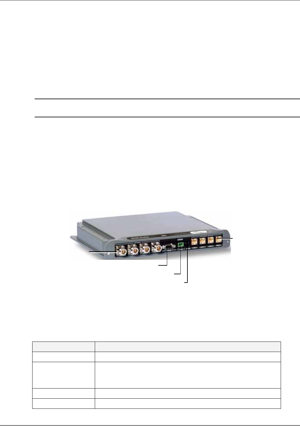
1.6.1 Front Panel Port Connections and LEDs
The front panel contains the antenna connections, local management port, mobile services
connections and power connections. The following figure shows the MA 850A1 front panel.
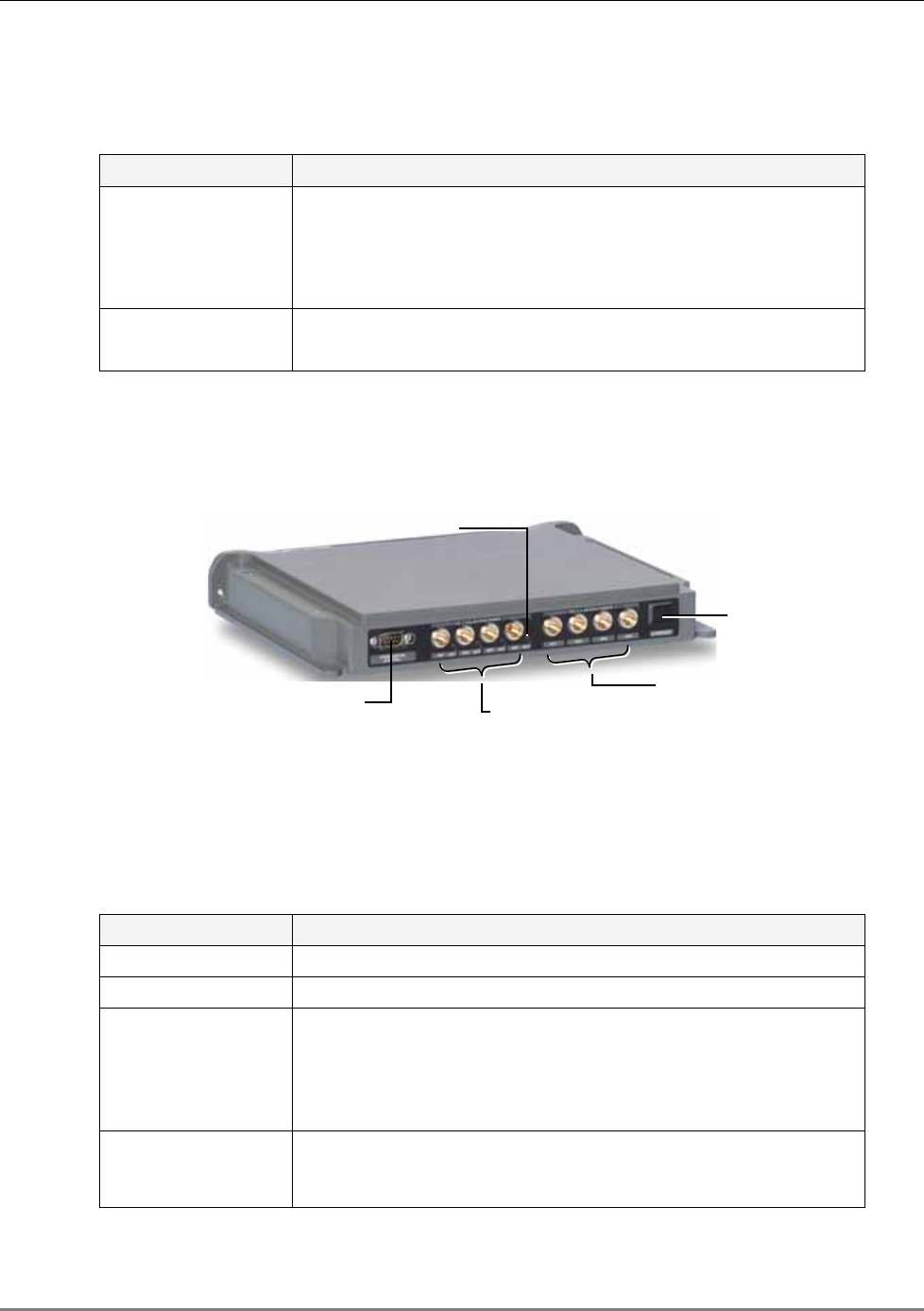
Figure 1-10. MobileAccess 850 Front View
Front Panel Ports
The following table describes the front panel ports.
Table 1-1. Front Panel Ports
Front Panel Ports Description
Antenna Ports Four n-type female antenna connections
Mobile Services Four SMA female connections to antenna ports of MA 1000 RHUs
or MA 2000 antenna ports.
NOTE: To be terminated with 50 ohm terminations when not in use.
Local RS232 connection for local configuration and management.
DC Power connection: 20V to 48V (see 2.3.3
Antenna ports
Mobile services
Local RS232 connection
Power
LEDs
MA 850A1 Connections, LEDs and Ports
MA 850A1A1 Installation and Configuration Guide 8
Front Panel LEDs
The front panel contains two LEDs, described in the following table.
Table 1-2. Front Panel LEDs
Front Panel LEDs Description
Run Internal operation and channel operation status:
Green blinking – unit OK
Off – fault detected in unit
Red blinking – failure of one of the channels
PWR (Unlabeled LED adjacent to the power connection).
Green – Power OK.
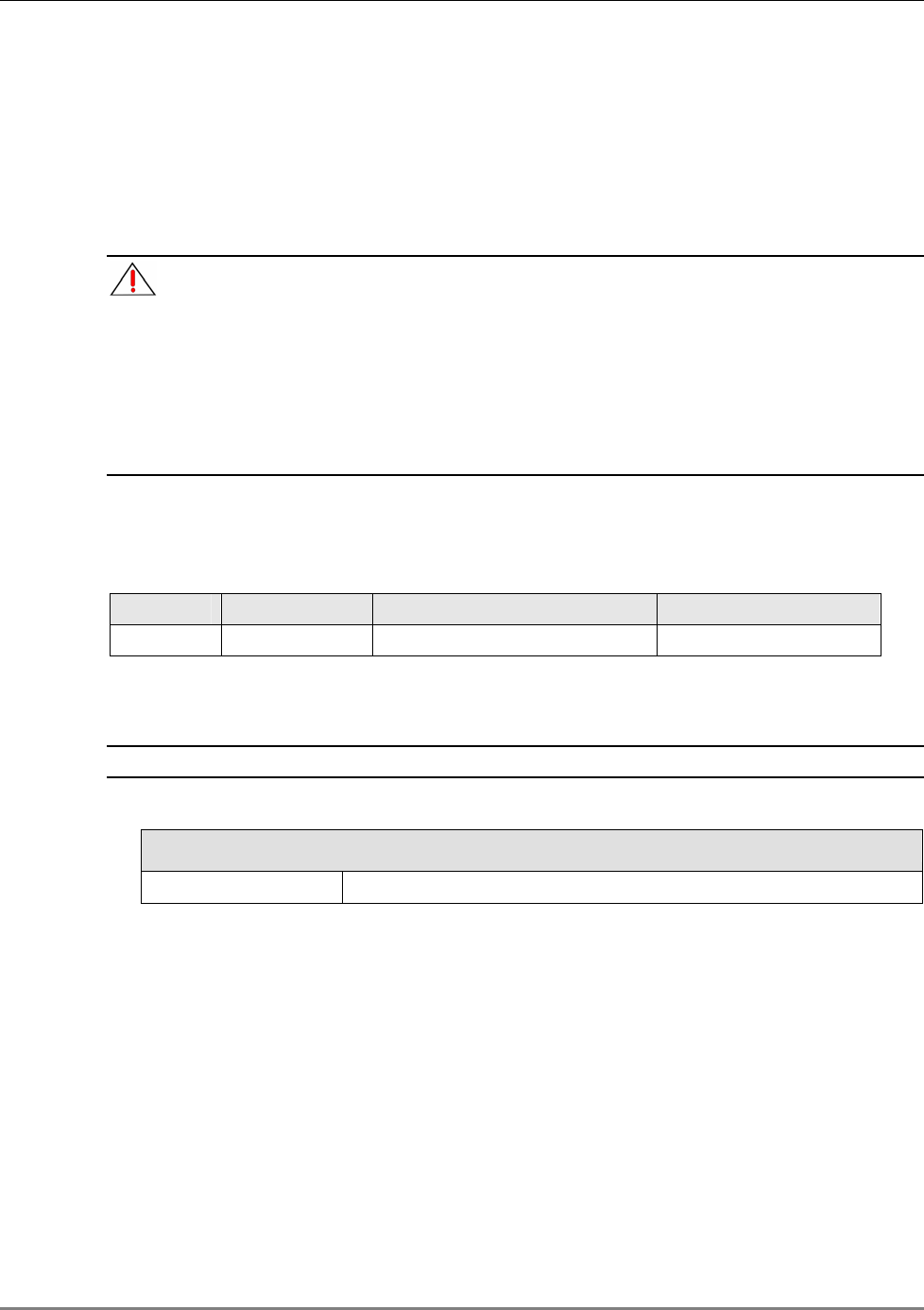
1.6.2 Rear Panel Port Connections and LEDs
The rear panel contains the 802.11a/b/g AP connections, Ethernet connection for remote
management and antenna sensing connector.
Figure 1-11. MobileAccess 850 Rear View
Rear Panel Ports
The following table describes the rear panel ports.
Table 1-3. Rear Panel Ports
Rear Panel Ports Description
802.11b/g APs Connection to four 802.11b/g APs.
802.11a APs Connection to four 802.11a APs.
Connection to
control
Relevant only when MA 1000 RHU services are integrated with
MA 850A1 services. Connects to the RHU rear panel Control
connector. Routes the antenna sensing (indication of whether
antenna is present) to the RHU for monitoring via the
management application. (RHU Version 3.1 and higher).
Ethernet port Connection to network for configuration and management
through a WEB browser.
The default IP Address is on the label
near the port.
802.11b/g APs
connections
Ethernet Port
802.11a APs
connections
Antenna sensing
connector
802.11b/g AP Status LEDs

MA 850A1A1 Installation and Configuration Guide 9
2
I
In
nf
fr
ra
as
st
tr
ru
uc
ct
tu
ur
re
e
P
Pr
re
ep
pa
ar
ra
at
ti
io
on
n
2.1 Installation Requirements
The infrastructure preparation consists of two main phases:
1. Floor Planning: Planning the distribution of the antennas on each floor to provide the
required coverage. This phase varies depending on whether the coverage is only for WLAN
or includes voice coverage through the existing infrastructure:
• For voice and WLAN 802.11b/g coverage only- Use only antennas listed in section
2.4.1 table I
• For voice and WLAN 802.11b/g/a coverage – Use only antennas listed in section 2.4.1
table II
2. Telecom Closet Planning: Planning the layout of the devices and cables in the telecom
closet or shaft. This includes the MA 850A1, 802.11 Access Points, cabling and other voice
service distribution systems such as MA 1000 that are relevant to the specific installation.

Coaxial Cable Connections
MA 850A1A1 Installation and Configuration Guide 10
2.2 Coaxial Cable Connections
2.2.1 General Cable Installation Procedures
The general cable installation procedures in accordance with the building codes in your area
should be observed. The building code requires that all cabling be installed above ceiling level
(where applicable). Each length of cable from the risers to each antenna must be concealed
above ceiling.
The cable must be properly supported and maintained straight. This is done either by using tie
wraps or cable trays and clamps or hangers every 10 feet (where practical above ceiling level).
Where this is not obtainable, the following should be observed:
• The minimum bending radius of the supplied ½” coax cable should be 7”.
• Cable that is kinked or has a bending radius smaller than 7” must be replaced.
• Cable runs that span less than two floors should be secured to mechanical structures
that are suitably located.
• The cables should be supported only from the building structure.
2.2.2 RF Rules
• Use coax ½”, 50ohm, male-to-male N-type, (6-7dB for 1Ghz, 11dB for 2Ghz) for
connecting to RHU and RHU ports.
• Use coax RG223, 50ohm, male-to-male N-type for RF connections from the BUs to the
BTS/RBS and to the RIU.
• When using the MobileAccess™ system in an environment in which other indoor
coverage systems are installed, it is recommended (where possible) that the antennas
are placed at least two meters apart
• When bending coax cables, verify that the bending radius does not exceed the coax
specifications.
• Use only antennas listed in section 2.4.1.
• Use a VSWR meter (i.e. Site Master or equivalent) for checking coax cables, including
the antennas. (<2). The VSWR must be measured prior to terminating the RHUs in the
remote communication rooms
• Terminate all unused MA 850A1 ports with a 50 ohm load
Power Consumption, Connections and Power Supplies
MA 850A1A1 Installation and Configuration Guide 11
2.3 Power Consumption, Connections and Power
Supplies
2.3.1 Power Safety Instructions
SAFETY WARNINGS
When installing or selecting the power supplies:
1. Be sure to disconnect all power sources before servicing.
2. Calculate the required power according to the requirements of the specific installation and
then determine the configuration of the power supplies. The required DC cables will then be
determined by the selected PS configuration.
3. Use only UL approved power supplies
4. AC and DC power supply cables – use only the power cords supplied with the units
2.3.2 MA 850A1 Power Consumption
Table
2-1. MobileAccess™ Power Requirements
Unit Type Voltage Input Typical Power Consumption Current Consumption
MA 850A1 20 to 48VDC 20W 1.0 A (max)
2.3.3 Types of Power Supplies
NOTE: Use only UL approved power supplies with SELV outputs.
Table
2-2: MobileAccess™ Power Supplies
Power Supply
LPS-48V-66W Local AC/DC Converter 66W
2.3.4 Power Connections
The power connections vary according to the MA 850A1A1 installation topology. The following
power supplies are recommended for local power configuration, where p
ower can also be
supplied using remote power supply configurations
.
• Use a dedicated power supply (i.e. LPS-48-66W – refer to the Power Supplies Manual)
for the following installations:
• MA 850A1 standalone
• Combined with ModuLite MRC or 2000 Cabinet/Lite
• LPS-48-100W (recommended)
• Combined with the MA 1000 RHU – feeds both modules
In-building Antennas
MA 850A1A1 Installation and Configuration Guide 12
2.4 In-building Antennas
The in-building antennas are connected to the coaxial cable distribution system by jumper cables
at various points. The antennas will be mounted on the ceiling tiles and should be exposed. All
in-building antenna installations will be such that it will not interfere with indoor traffic and will
not enable any person to touch the antennas.
• Wideband antennas omni – up to 2.5GHz to support 802.11b/g, up to 6GHz to support
802.11a. Use antennas listed in section 2.4.1
• 50 ohm impedance
2.4.1 Antenna Types
These antenna types are to be used with the MA-850A1 device.
NOTE: If your installation distributes 802.11b/g only, you may use any of the first three vendor
types of listed antennas: Mars Antennas, Cellwave or Antenna Specialists. For 802.11a/b/g
service distribution, use antennas from the second table below.
Table 2-3. Antennas to be used for 802.11b/g
Vendor Catalog number Gain [dBi]
Mars Antennas MA-CM36-15 2 low band
3-4 high band
5 WLAN 802.11b
Cellwave A08818DC00-28T0 2.1
Antenna Specialists ASP-3561 2
Table 2-4. Antennas to be used for 802.11b/g/a
Vendor Catalog number Gain [dBi]
Huber+Suhner SWA 0859/360/4/10/V 7 dBi
Mars Antennas MA-CP26-2X 2 low band
3-4 high band
6 WLAN 802.11a
2.4.2 Antenna Connections
• 50 Ω, 1/2” or 3/8” Plenum coax cables
• Max cable length (typically): 150’
• 50 ohm terminator on unused connections
• For short jumpers (to MRC antenna ports): RG223 2 ft or 10 ft male-to-male coax
jumpers

Access Points
MA 850A1A1 Installation and Configuration Guide 13
2.5 Access Points
The following vendor Access Points have been verified and FCC approved.
Table 2-5. Approved Access Points
Vendor Catalog number FCC-ID
Cisco
AIR-AP124AG-A-K9
802.11b/g
LDK102056

MA 850A1A1 Installation and Configuration Guide 14
3
I
In
ns
st
ta
al
ll
la
at
ti
io
on
n
3.1 Accessory Kits
Verify that the supplied accessory kit corresponds to your installation. The accessory kits include
a bracket, the required cables and accessories.
AK-850-1000 Accessory kit for 850 with 1000
AK-850-1200 Accessory kit for 850 with 1200
AK-850-MDLT Accessory kit for 850 with Modulite
AK-850-2000 Accessory kit for 850 with 2000
AK-850-SA Accessory kit for 850 stand alone
3.2 Positioning the Unit
MobileAccess 850 is typically installed in the communication shaft or cabinet of each floor to
which WLAN coverage is to be supported. The accessories, mounting and installation
procedures vary depending on the configuration.

MA 850A1 Installation and Connections
MA 850A1A1 Installation and Configuration Guide 15
3.3 MA 850A1 Installation and Connections
MA 850A1 may be installed in the following configurations:
• Wall mount standalone – mounted directly on the wall with four screws
• Mounted onto an MA 1000 RHU
• Mount as add-on to an MA 1000 RHU with an MA 1200 add-on unit
• Add-on to a MA 2000 system
NOTE: It is recommended to record the location of the units according to the MAC addresses
on the sticker at the rear of the units near the Ethernet port.
In a wall-mount standalone configuration, MA 850A1 is mounted to the wall using four screws.
When mounted to another MA remote (MA 1000 with or without MA 1200, MA 2000), a special
bracket and set of accessories is used. A different bracket and set of accessories is used for
each type of installation.
Note: Use SMA wrench for the SMA connectors, do not over tighten the connectors.
3.3.1 Wall Mount Standalone
NOTE: Although it is not required for a stand-alone installation, it is recommended to set the
supplied cable 705102101 aside (usually used when MA 850A1 is installed in an add-on
configuration).You will need it if you want to upgrade your system to provide additional coverage
options.
1. Mount the MA 850A1 on the wall using four screws. When mounting,
consider the following:
• The type of screws used to mount the unit must suit the type of wall construction
(cement, bricks, etc.) so that the mount is secure.
• The position of the APs and required cable connections.
2. Connect the power ( 2.3.4).
3. Connect the 802.11a/b/g Access Points to the corresponding ports on the
MA 850A1 rear panel (section 3.4).
4. Connect the coax antenna cables to the MA 850A1 unit antenna ports on
the MA 850A1 front panel (section 3.6).
5. Fit 50 ohm terminators on all unconnected SMA, AP and antenna ports.
6. Connect the network connection to the MA 850A1 rear panel network port.
NOTE: Each unit is pre-assigned an IP address. The address can be modified anytime through a
remote connection according to the procedure described in section
4.2.1).
MA 850A1 Installation and Connections
MA 850A1A1 Installation and Configuration Guide 16
3.3.2 Mounted onto MA 1000
In this type of installation, the MA 850A1 is assembled onto the MA 1000 RHU using a special
bracket.
1. Secure the supplied bracket to the top of the MA 1000 RHU.
2. Assemble the MA 850A1 on top of the bracket.
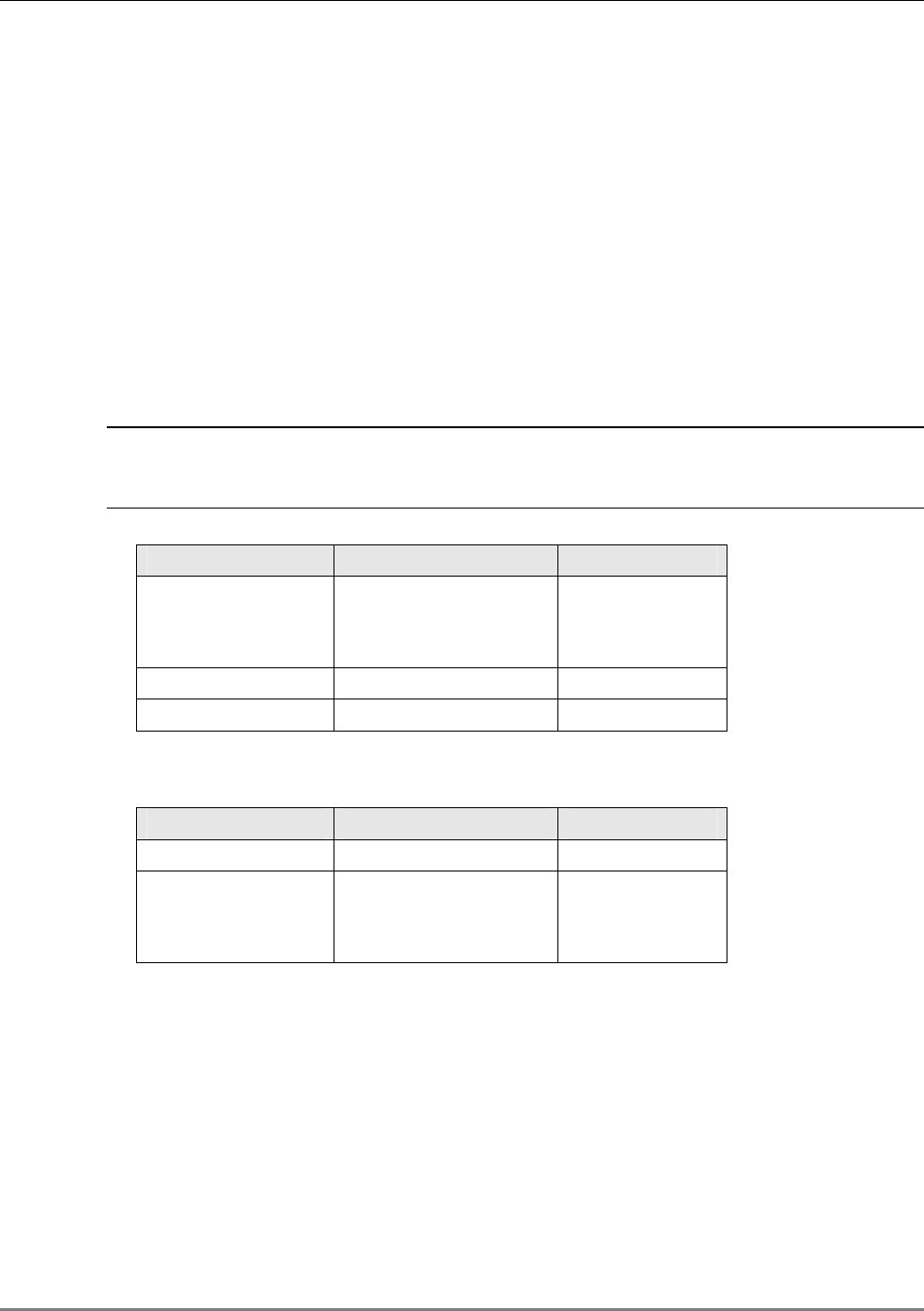
3. Connect between MA 850A1 and MA 1000 as follows:
• For antenna sensing support (RHU 1000 version 3.1 and higher), connect between the
Control connectors at the rear of both units using cable 705102101
NOTE: For antenna sensing support in RHU 1000 version 3.0 and lower, upgrade to version 3.1
according to the MA 850A1 Upgrade Procedure Guide.
.
Figure 3-1. Control connector
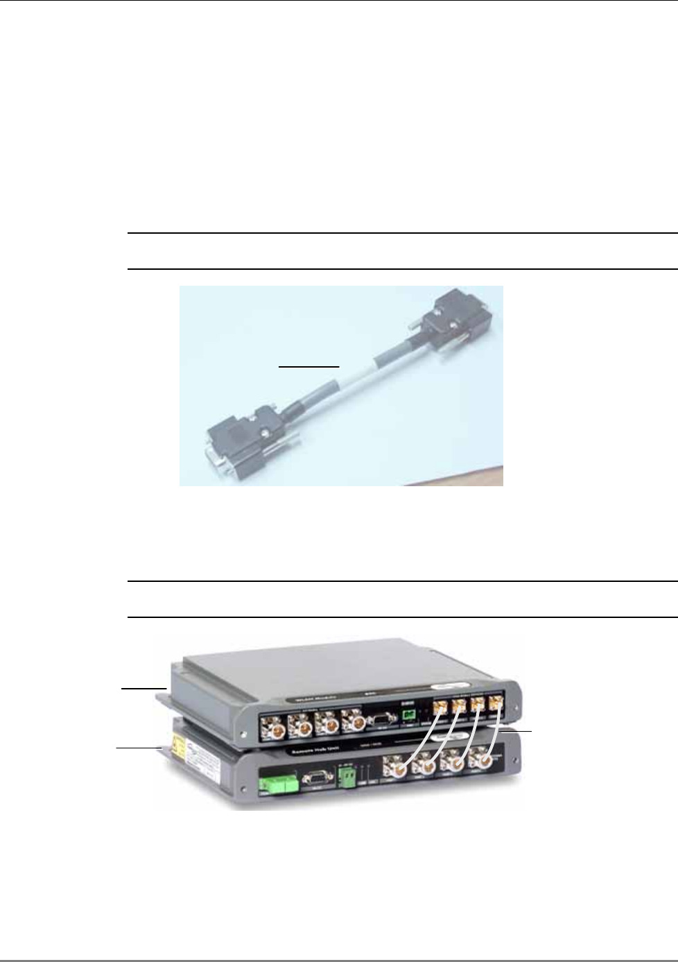
• Connect the MA 1000 antenna ports and the MA 850A1 Mobile Services ports using
the four SMA to N-type cables
supplied in the accessory kit
.
NOTE: Be sure the connectors are closed at a 45 degree angle so as not to place stress on the
cables.
Figure 3-2. Antenna to SMA Connections
7. Connect the power ( 2.3.4).
8. Connect the 802.11a/b/g Access Points to the corresponding ports on the
MA 850A1 rear panel (section 3.4).
70510210
Antenna to SMA
connections
MA
850
A
1
MA 1000
MA 850A1 Installation and Connections
MA 850A1A1 Installation and Configuration Guide 17
9. Connect the coax antenna cables to the MA 850A1 unit antenna ports on
the MA 850A1 front panel (section 3.6).
10. Fit 50 ohm terminators on all unconnected SMA, AP and antenna ports.
11. Connect the network connection to the MA 850A1 rear panel network port.
NOTE: Each unit is pre-assigned an IP address. The address can be modified anytime through a
remote connection according to the procedure described in section
4.2.1).
3.3.3 Mounted onto an MA 1200 / MA 1000 Installation
The installation varies depending on whether the MA 850A1 is to be added to an existing
installation of MA 1200 and MA 1000 or if this is a new installation:
• New installation - install the
MA 850A1 first
and mount the MA 1000 followed by the MA
1200 on top of the MA 850A1;
• Existing installation - install the MA 850A1 on top of the MA 1200.
As an existing installation
In this type of installation, the MA 850A1 is assembled onto the MA 1000 RHU using a special
bracket.
1. Secure the supplied bracket to the top of the MA 1200 add-on.
2. Assemble the MA 850A1 on top of the bracket.
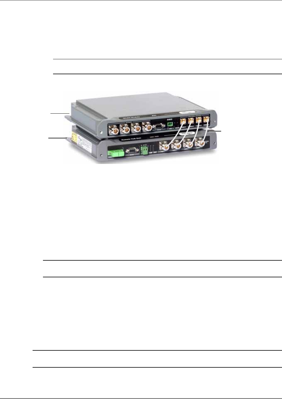
Figure 3-3. Connection of MA 850A1 and MA 1000 Service Ports
MA 1200
MA 850A1
MA 1000
MA 850A1 Installation and Connections
MA 850A1A1 Installation and Configuration Guide 18
3. Connect the MA 850A1 to the MA 1000 / MA 1200 and MA 1000 as follows:
• Connect the MA 1000 antenna ports and the MA 850A1 Mobile Services ports using
the four SMA to N-type cables
supplied in the accessory kit
.
NOTE: Be sure the connectors are closed at a 45 degree angle so as not to place stress on the
cables.
Figure 3-4. Antenna to SMA Connections
4. Connect the power ( 2.3.4).
5. Connect the 802.11a/b/g Access Points to the corresponding ports on the MA 850A1 rear
panel (section 3.4).
6. Connect the coax antenna cables to the MA 850A1 unit antenna ports on the MA 850A1
front panel (section 3.6).
7. Fit 50 ohm terminators on all unconnected SMA, AP and antenna ports.
8. Connect the network connection to the MA 850A1 rear panel network port.
NOTE: Each unit is pre-assigned an IP address. The address can be modified anytime through a
remote connection according to the procedure described in section
4.2.1).
3.3.4 Add-on to a MA 2000 System
MA 850A1 may be integrated into the MA 2000 system using one of the following installations:
• Installing it directly on the MA 2000 RC top panel (using the supplied plate);
• Mounting it on a rack (using the supplied plate);
• Wall-mount near the MA 2000 cabinet.
NOTE: The coax outputs of the cabinet are connected to the appropriate ports on the MA 850A1
and the antennas are connected directly to the MA 850A1 module.
Antenna to SMA
connections
MA
850
A
1
MA 1000
MA 850A1 Installation and Connections
MA 850A1A1 Installation and Configuration Guide 19
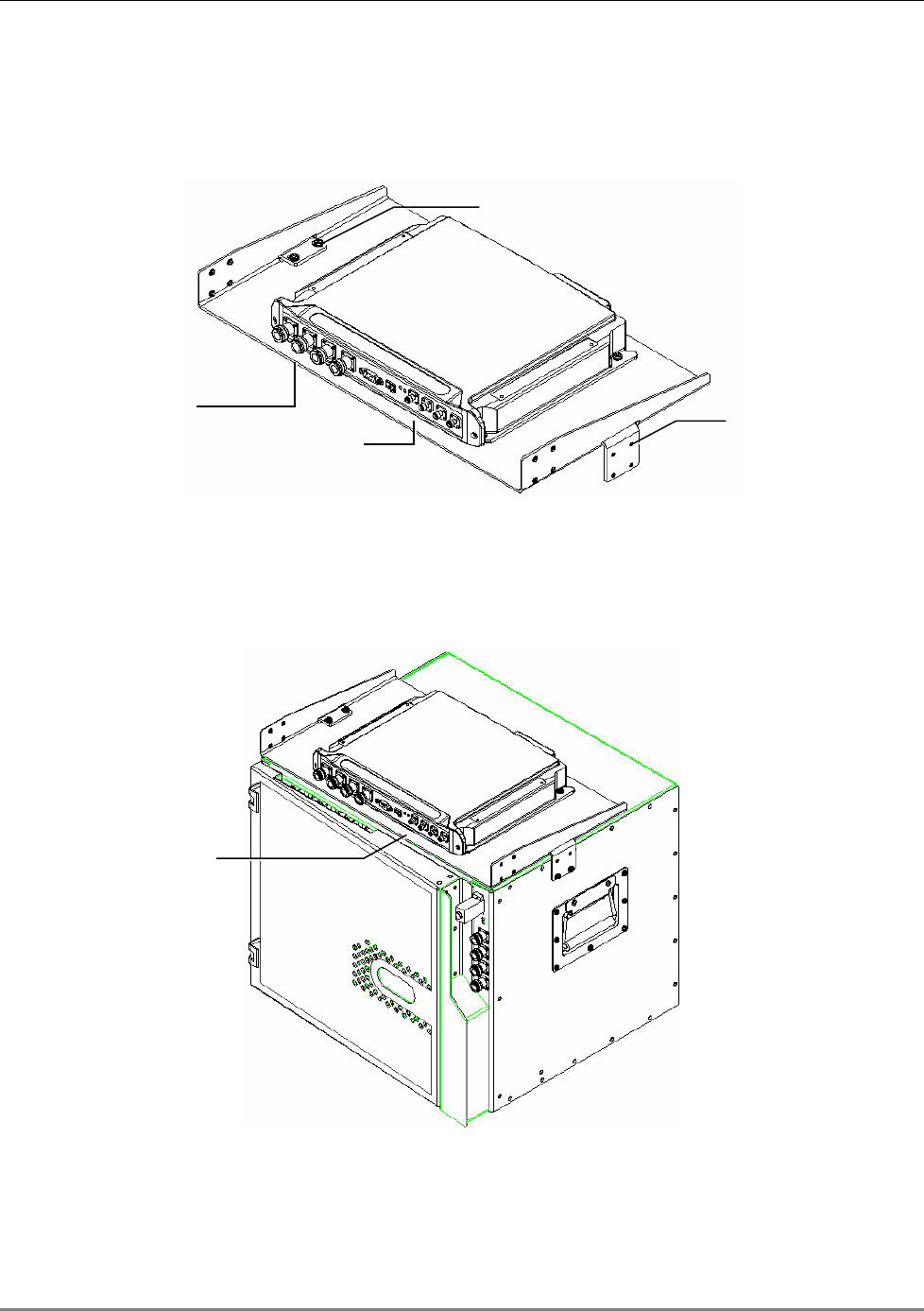
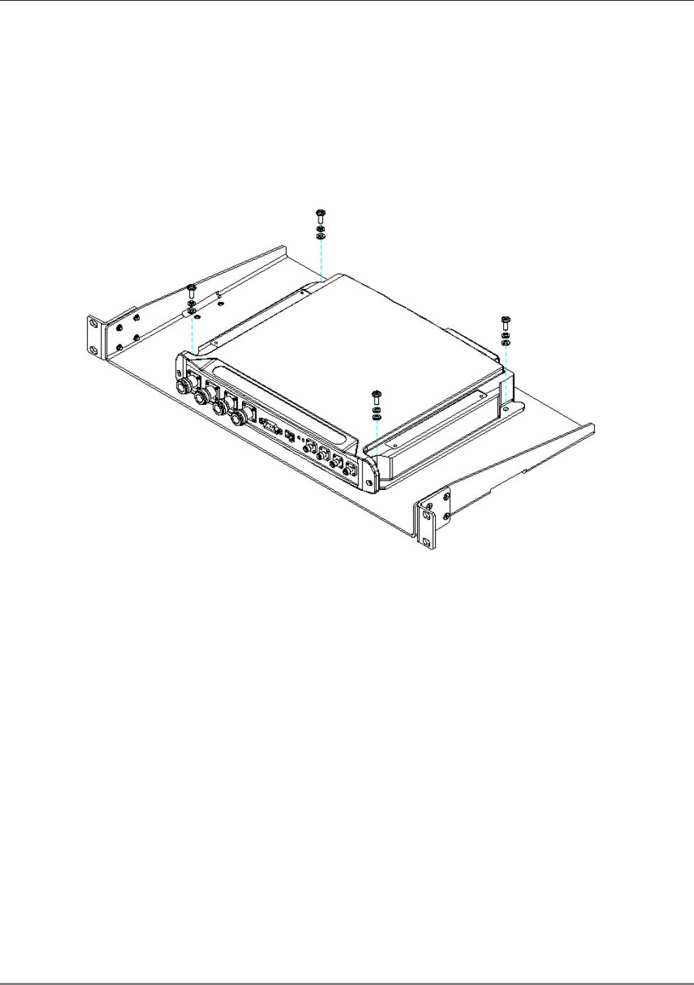
3.3.4.1 MA 850A1 RC 2000 Assembly
1. Assemble two side brackets to the plate sides as illustrated in Figure 3-5.
2. Assemble the MA 850A1 module to the supplied bracket using the four screws and washers
as illustrated below.
Figure 3-5. MA 850A1 Rack Installation
3. Assemble the plate to the MA 2000 RC by securing the brackets to the cabinet sides as
illustrated below.
Figure 3-6. Illustration of MA 850A1 Mounted on MA 2000 RC
Side bracket
assembly
Connections to Remote
Cabinet antenna ports
Connections to
antennas Side bracket
assembly
Connection to
Remote Cabinet
antenna
p
orts
MA 850A1 Installation and Connections
MA 850A1A1 Installation and Configuration Guide 20
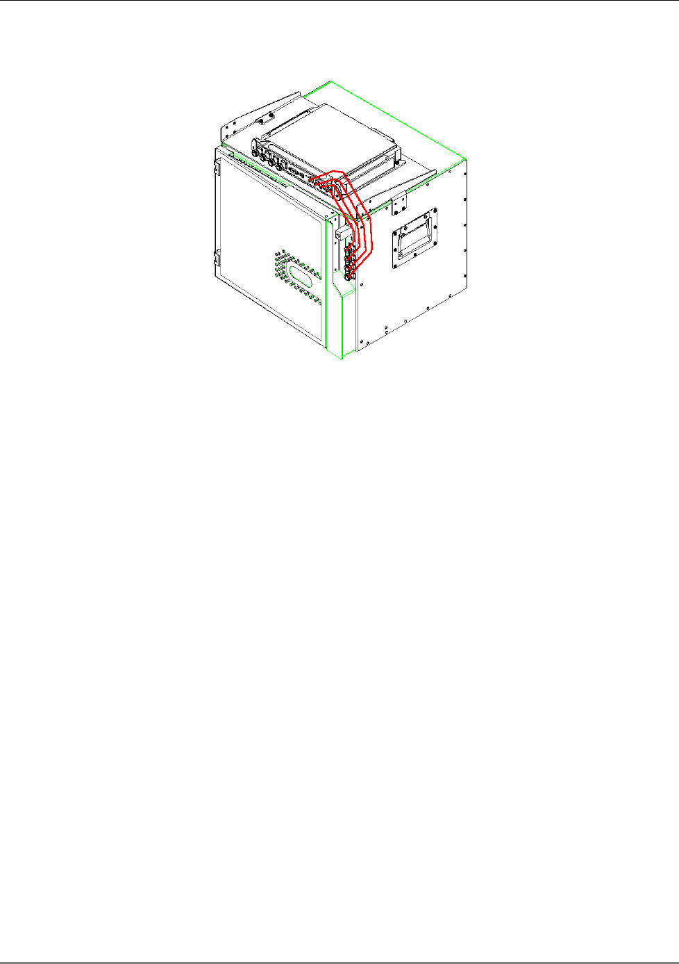
4. Connect the RC antenna ports to the MA 850A1 front panel port connectors as illustrated
below.
Figure 3-7. Illustration of RC Antenna port connections
5. Connect the antennas to the MA 850A1 antenna ports.
MA 850A1 Installation and Connections
MA 850A1A1 Installation and Configuration Guide 21
3.3.4.2 MA 850A1 Rack Mount
1. Assemble the side brackets as illustrated in Figure 3-5.
2. Assemble the MA 850A1 module to the supplied bracket using the four
screws and washers.
3. Mount the assembly in the rack using the side brackets.
Figure 3-8. MA 850A1 to Bracket Installation
4. Connect the RC antenna ports to the SMA connectors on the MA 850A1
front panel.
5. Connect the antenna to the MA 850A1 antenna ports.
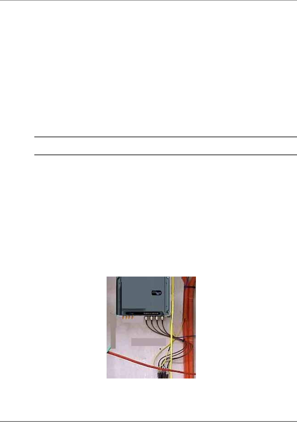
3.3.4.3 MA 850A1 Wall Mount Installation
The MA 850A1 may be mounted independently on the wall near the RC cabinet.
• Connect the RC antenna ports to the SMA connectors on the MA 850A1 front panel.
• Connect the antenna to the MA 850A1 antenna ports.
802.11a/b/g AP Connections
MA 850A1A1 Installation and Configuration Guide 22
3.4 802.11a/b/g AP Connections
This section describes the MA 850A1 ports to be connected to the 802.11a/b/g APs. The antenna
zone over which the signal is distributed corresponds directly to the AP port connection,
therefore, when connecting the 802.11 APs, keep in mind the area to be covered.
Refer to
section 1.4 for a description of the distribution patterns.
For example, connecting 802.11a APs to 802.11a inputs 2 and 3 will distribute these signals
though antenna ports 2 and 3. Connecting the 802.11b/g APs to 802.11b/g inputs 1, 2 and 3,
will distribute the signals over antenna ports 1, 2 and 3.
All signals are combined and routed
through the same coax and antenna infrastructure.
NOTE: It is recommended to RESET the unit by removing and reinserting the power
connector on the front panel after connecting the APs.
3.5 MA 1000/2000 Remote Unit Connections
• Use short 50 Ω Coax cables w/N-Type connectors
3.6 Antenna Connections
• 50 Ω, N-type male to male, 1/2” or 3/8” Plenum coax cables
• Max cable length (typically): 150’
• 50 ohm terminator on unused connections
• For short jumpers (to MA 1000 RHU, MA 2000 or MRC antenna ports): RG223 2 ft or 10
ft male-to-male coax jumpers
Figure 3-9. Antenna Connections

MA 850A1A1 Installation and Configuration Guide 23
4
C
Co
on
nf
fi
ig
gu
ur
ra
at
ti
io
on
n
a
an
nd
d
M
Ma
an
na
ag
ge
em
me
en
nt
t
It is required to perform the following configuration procedures:
• Change the default IP address
• Connected antennas (if not all antennas are connected)
NOTE: The configuration may be performed either before or after installation.
The configuration can be performed either through:
• For professional installers only: A local connection to the unit (requires installing the
application on the computer)
• For all users: A remote connection through a Web browser application
NOTE: A local connection has priority over a WEB connection. A WEB connection will not be
operational if there already is a local connection and the unit stop responding if a local
connection is initiated while a WEB session is open.
After configuring the unit, each channel and the corresponding element may be monitored.
Local Configuration and Monitoring
MA 850A1A1 Installation and Configuration Guide 24
4.1 Local Configuration and Monitoring
This procedure is performed through the MA 850A1 Customer Tool application installed and
launched from a computer that is locally connected to the MA 850A1 unit.
For professional installer only
This procedure is performed through the MA 850A1A1 Customer Tool application installed
and launched from a computer that is locally connected to the MA 850A1A1 unit.
4.1.1 Getting Started
1. Install the 850 MA Customer Tool application on your computer.
2. Locally connect to the MA 850A1 Local connector using the RS232 9-pin cable provided with
the MA 850A1 unit.
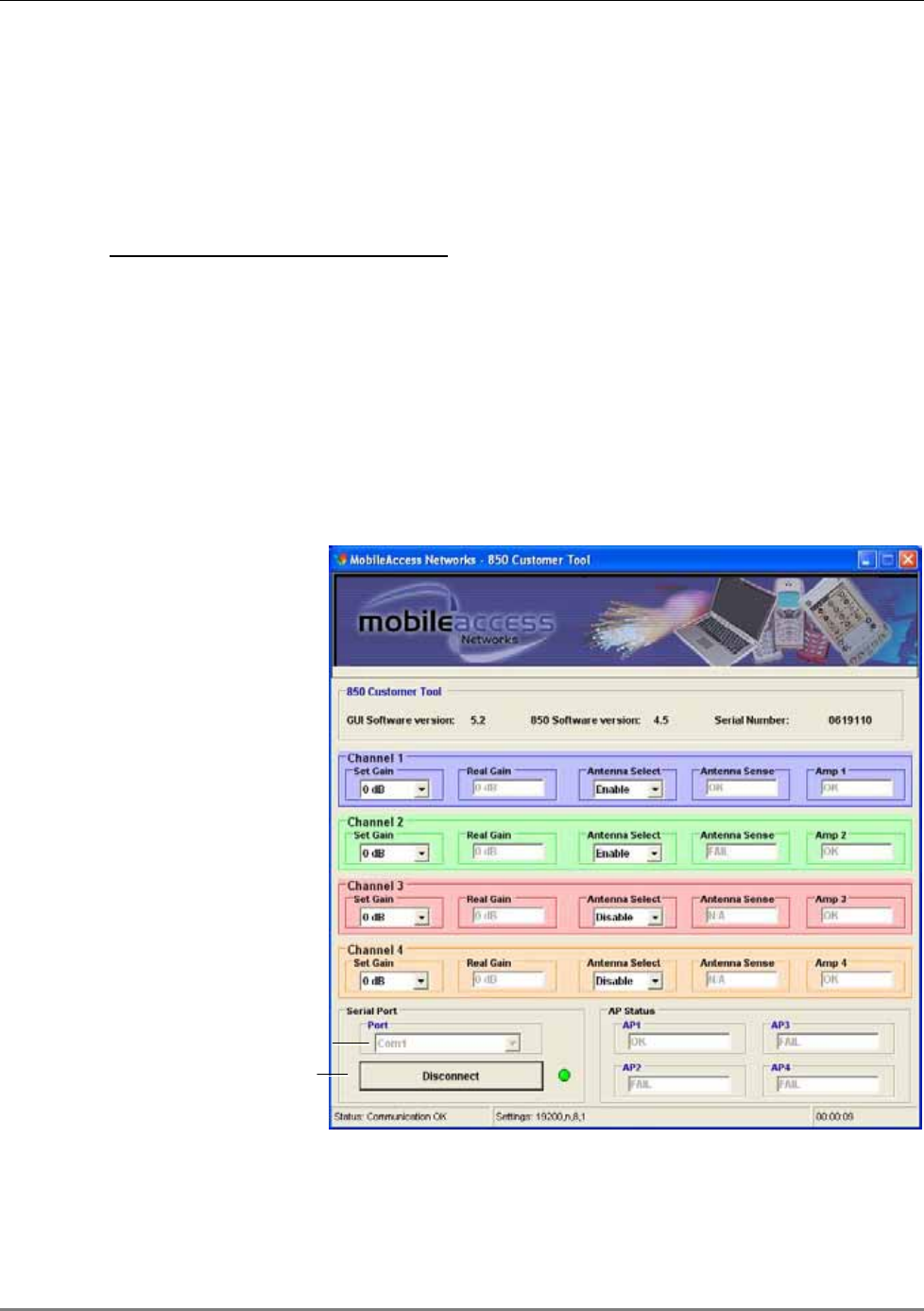
3. Launch the application on the computer. The MA 850A1 Customer Tool dialog appears.
Figure 4-1. Connecting to the MA 850A1
4. Under Serial Port, Select the com port corresponding to the currently connected computer
RS232 port and click Connect. The dialog options are described in the following sections.
Set Comm port
Connect
Local Configuration and Monitoring
MA 850A1A1 Installation and Configuration Guide 25
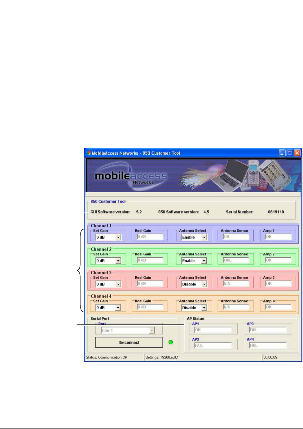
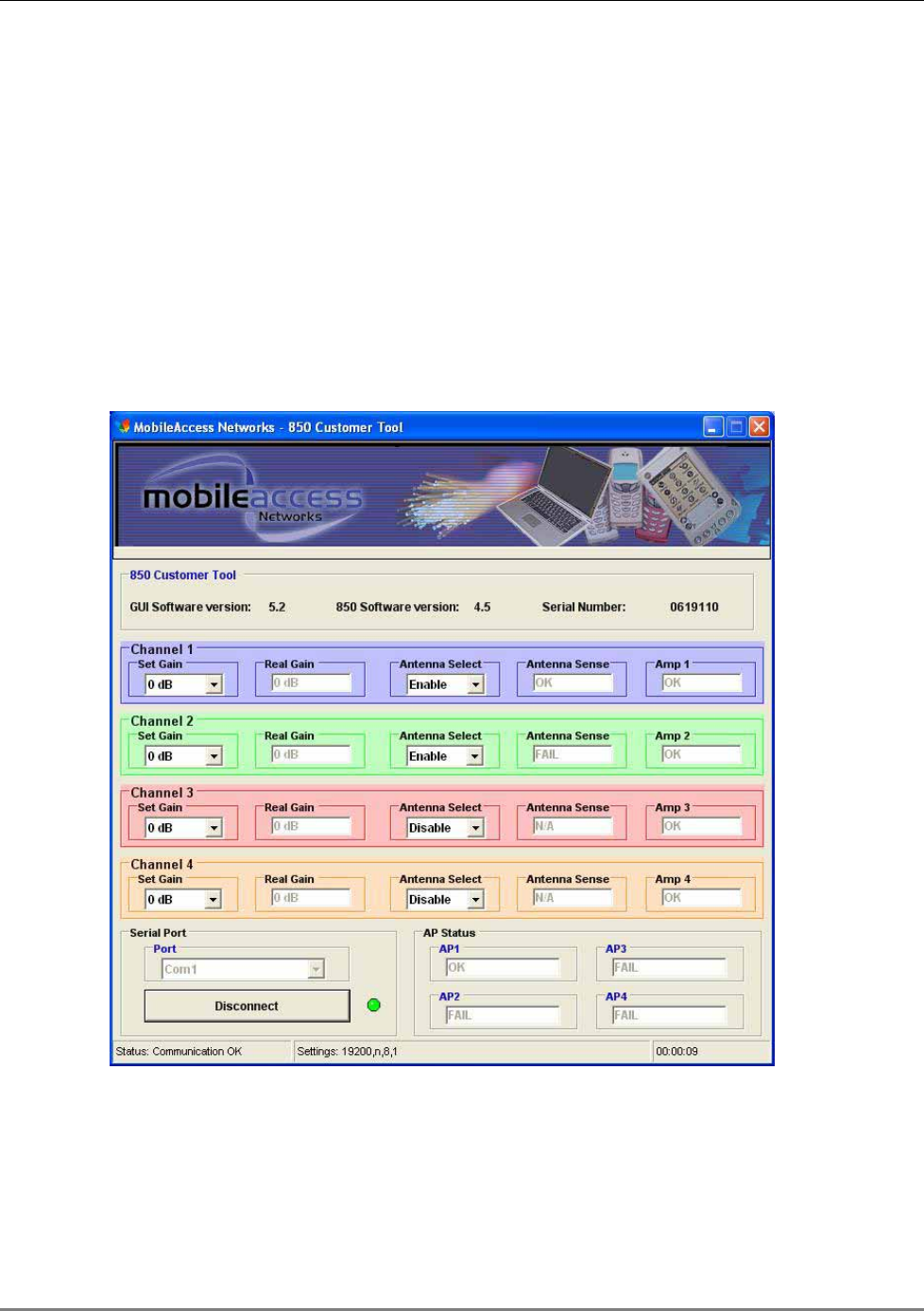
4.1.2 MA 850A1 Customer Tool Window Description
The MA 850A1 Customer Tool window is displayed according to the instructions in the previous
section. The window provides the channel configuration and monitoring options. It is divided into
the following areas:
• General information – versions, etc.
• Four channel areas – contain channel gain setting, antenna connections and channel
status
• AP Status – AP status and redundancy options
• Connection options – at the bottom left side of the window
Figure 4-2. MA 850A1 Customer Tool Dialog
General information
Channel and antenna
configuration
AP status
Local Configuration and Monitoring
MA 850A1A1 Installation and Configuration Guide 26
4.1.3 Configuration Using MA 850A1 Customer Tool
1. It is assumed that you are now locally connected to the MA 850A1 and have launched the
Customer Tool on you computer according to the instructions in the previous sections.
2. All antennas are configured by default as being connected (Antenna Select – Enable). For
channels where an antenna is not connected, under Antenna Select, choose Disable.
The Antenna Sense for the corresponding antenna will indicate N/A (not applicable).
3. By default, the Gain for each channel is set to 0dB. To change the coverage area per
channel, change the Gain for the specific channel.
4.1.4 Monitoring Using MA 850A1 Customer Tool
The MA 850A1 Customer Tool enables the user end-to-end monitoring of the channel status and
elements.
MA 850A1 Customer Tool Monitoring functions include:
• Antenna connection status – Antenna Sense for the corresponding channel, where:
• OK – antenna connection detected
• Fail – antenna not detected
• N/A – Antenna Select is set to Disable, meaning that an antenna is not connected to
the corresponding port
Remote - Web Browser Session
MA 850A1A1 Installation and Configuration Guide 27
• Channel status – under Amp 1 to Amp 4 for the corresponding channel:
• OK – channel OK
• Fail – channel failure
• AP Status:
• OK – AP detected
• Fail – AP not detected at the port.
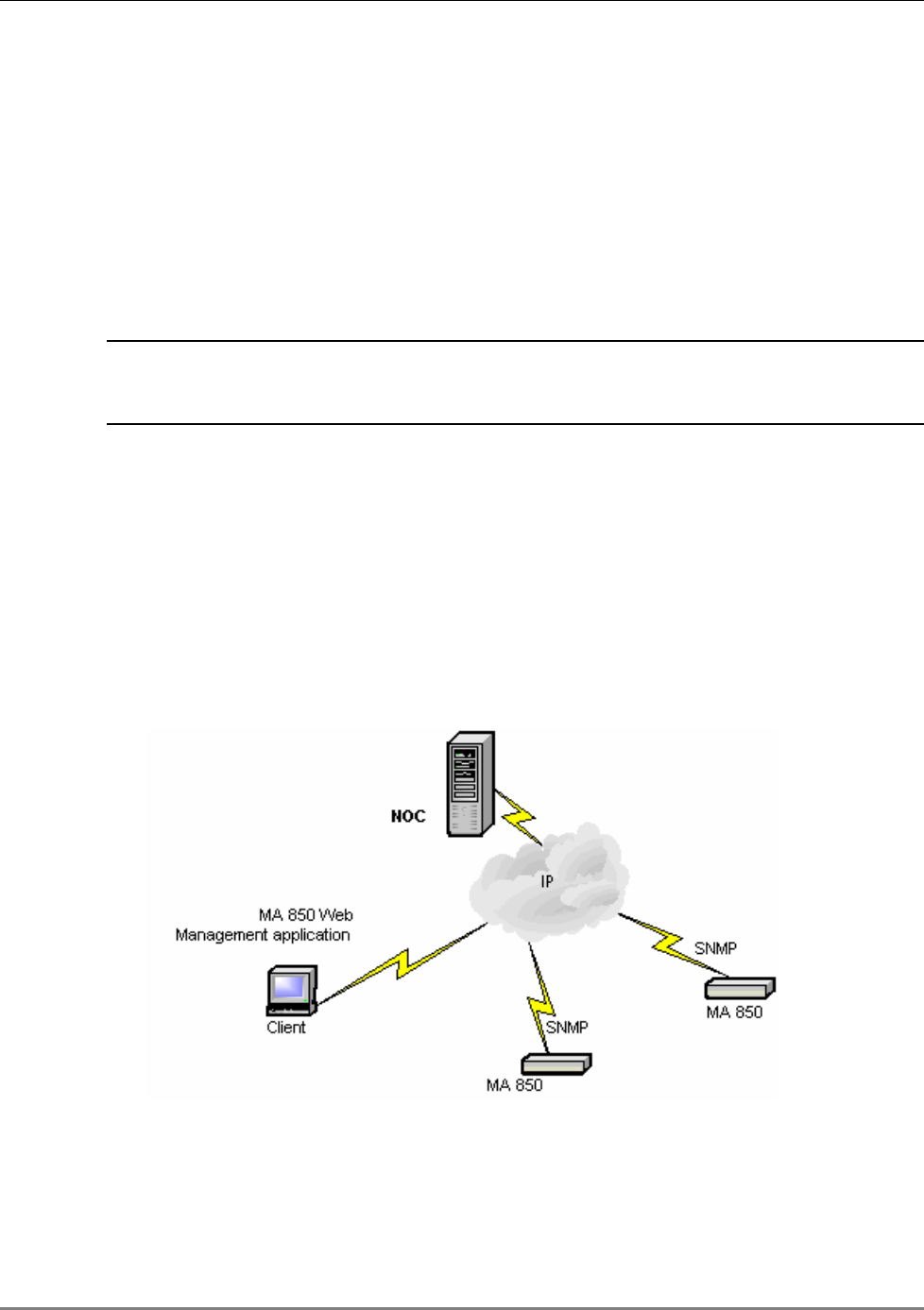
4.2 Remote - Web Browser Session
NOTE: Be sure that there is not an open local session (section
3.4) to the MA 850A1
unit before you attempt to open a remote session to the same unit; otherwise, the
unit may stop responding.
MA 850A1 whose SNMP parameters are defined may be connected to the network through an
Ethernet connection and assigned addresses either through dynamic (DHCP) or static address
assignment methods. The MA 850A1 units may then be remotely managed from any Web
Browser by connecting to the IP Address of the specific MA 850A1 unit or through any Network
Operating Center (NOC) using SNMP.
Once the network connections have been defined (section 4.2.1), the following operations may
be performed remotely through a Web browser:
• Configure gain setting for each channel (section 4.3)
• View alarms (section 4.4)
Figure 4-3. MA 850A1 Remote Management
Remote - Web Browser Session
MA 850A1A1 Installation and Configuration Guide 28
4.2.1 IP Configuration Procedure
MA 850A1 units connected to the network may be assigned either dynamic IP Addresses through
DHCP or static IP addresses (for networks without DHCP). The addresses may be assigned from
a single location using the Lantronix DeviceInstall application supplied with the units.
The IP configuration procedure consists of the following steps:
• Installing and launching the Lantronix DeviceInstaller application on your computer.
Connecting to the Network, page 28
• Performing Auto-Discovery, page 28
• For networks without DHCP – Assigning a Static IP Address, page 29
• Configuring the SNMP Parameters, page 33
4.2.1.1 Connecting to the Network
Connect each MA 850A1 unit
first
to the
network
and
then
to the power cable.
NOTE: It is recommended to record the location of the units according to the MAC addresses
on the sticker at the rear of the units near the Ethernet port.
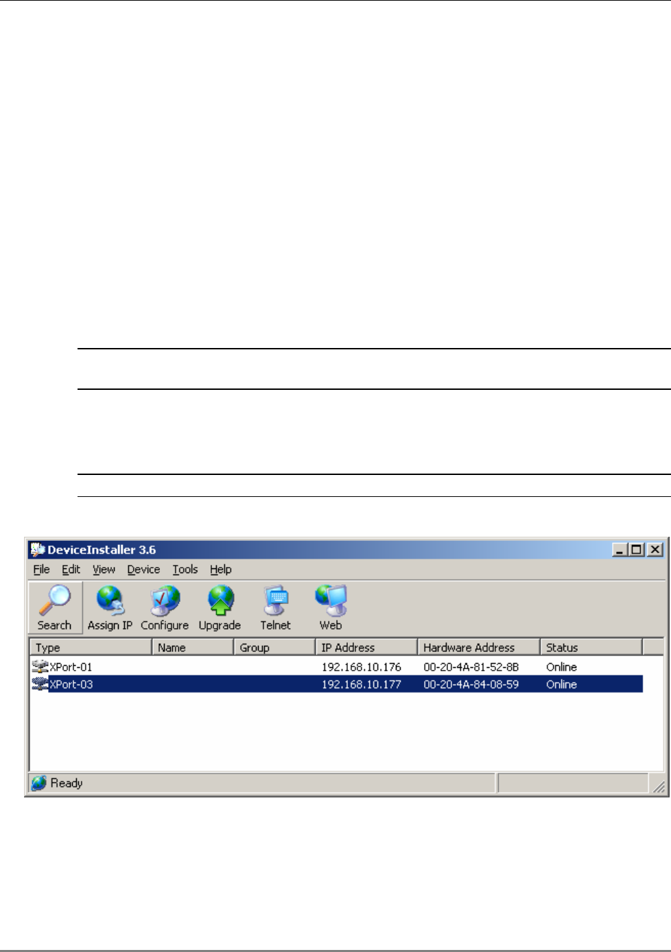
4.2.1.2 Performing Auto-Discovery
NOTE: Be sure the installed version is 3.6 or higher.
1. Install and launch the Lantronix DeviceInstaller application on your computer.
Figure 4-4. DeviceInstaller dialog
2. In the DeviceInstaller main window toolbar, click Search to perform auto-discovery. The
MA 850A1 units currently in the network will be identified and listed in the window
according to:
• Type - communication hardware version - xPort-01 or xPort-03
Remote - Web Browser Session
MA 850A1A1 Installation and Configuration Guide 29
• Hardware Address – MAC address
• Additional identification parameters that may be available
3. For networks with DHCP:
• The dynamically assigned IP Address will also be listed in the IP Address column.
4. For networks without DHCP:
• Disregard the data displayed in the IP Address column and assign a Static IP address
according to Assigning a Static IP Address, page 29.
What next ?
Define the SNMP parameters according to Configuring the SNMP Parameters, page 33.
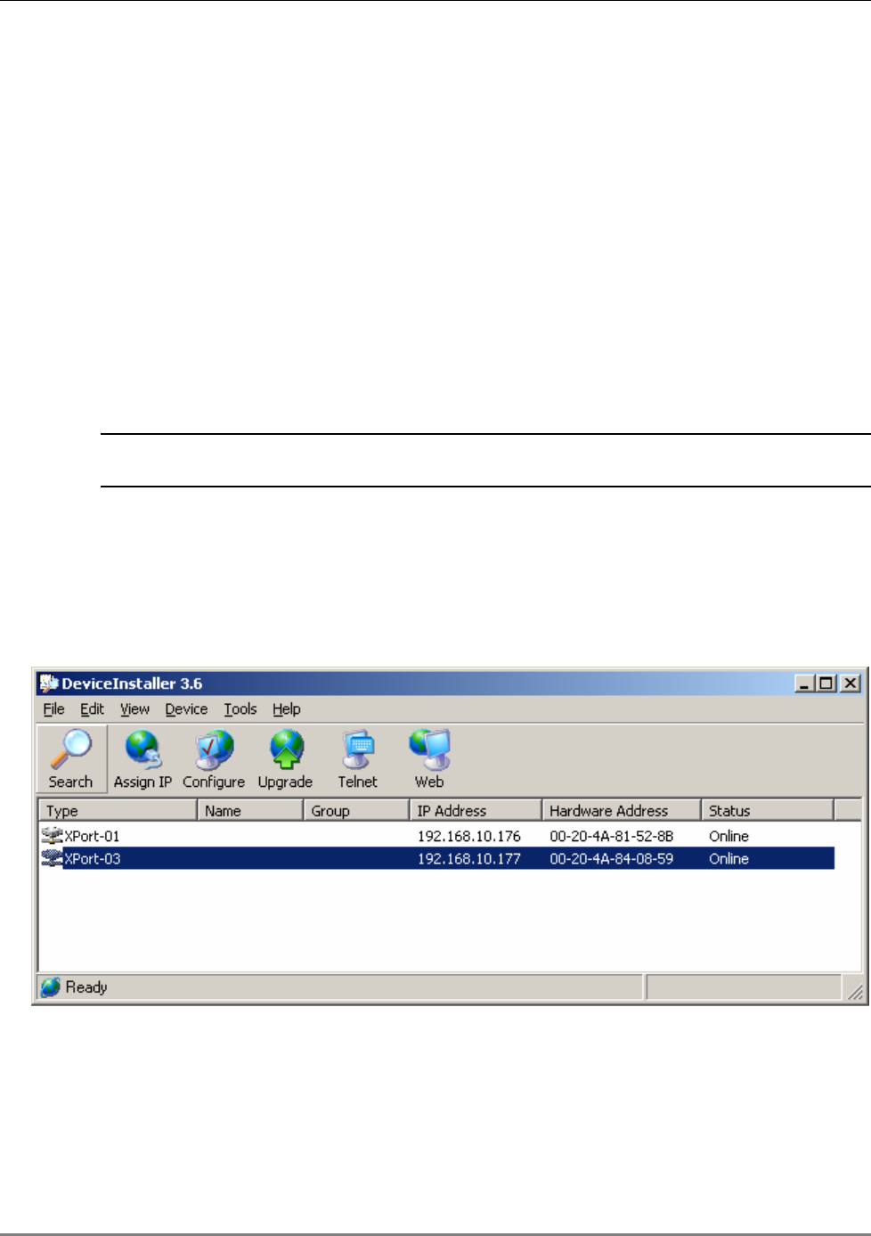
4.2.1.3 Assigning a Static IP Address
NOTE: This procedure requires the MAC address of the MA 850A1, which is found on the label
located at the rear of the unit.
Perform the following procedure for each of the MA 850A1 units listed in the
Lantronix DeviceInstaller main window which are to be manually assigned IP
Addresses.
1. Select the MA 850A1 unit and click the icon Assign IP in the toolbar.
Figure 4-5. Assigning Static IP Address
The Device Identification window appears, showing the MAC address of the selected MA
850A1 unit.
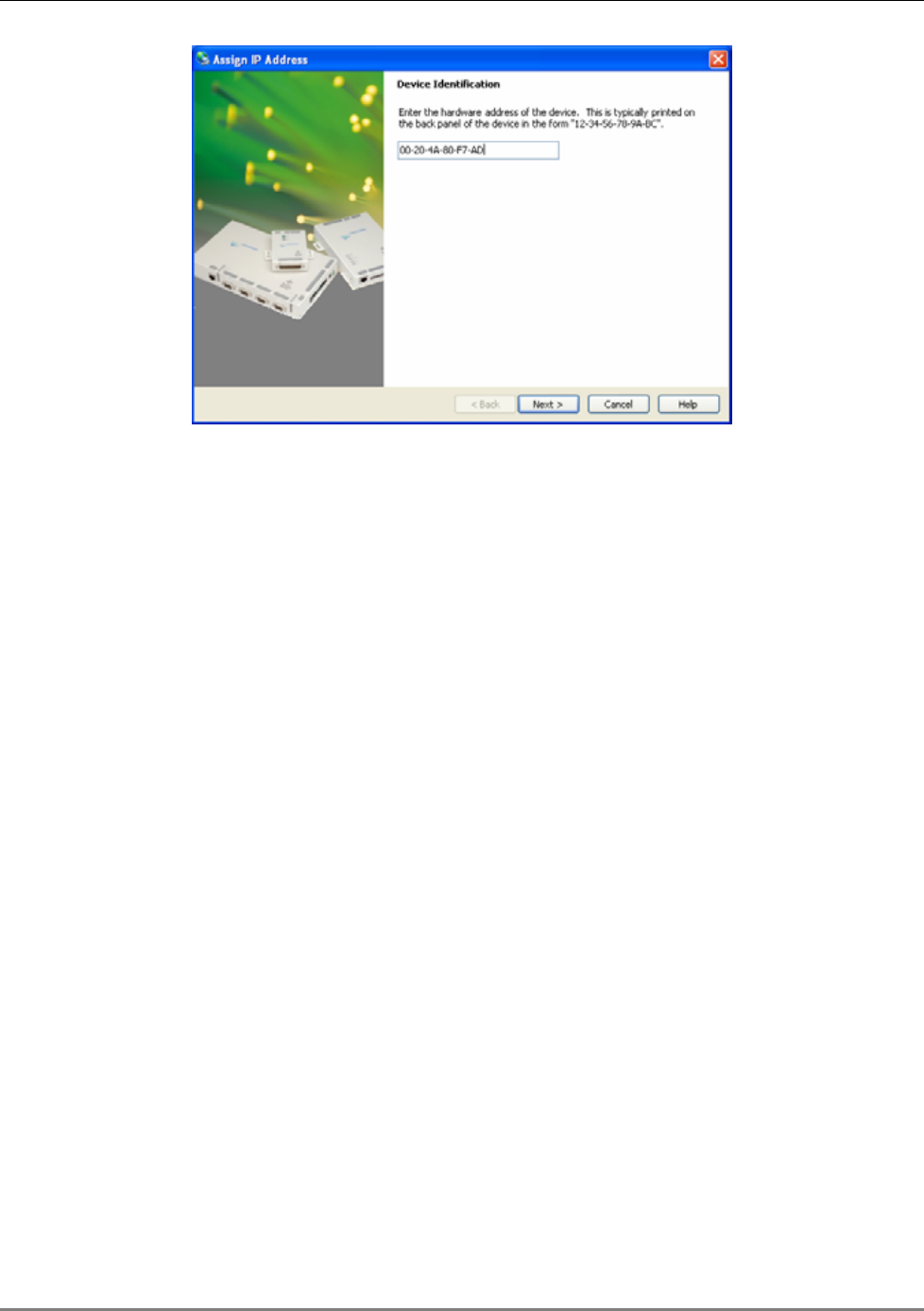
Remote - Web Browser Session
MA 850A1A1 Installation and Configuration Guide 30
Figure 4-6. MAC Address
Remote - Web Browser Session
MA 850A1A1 Installation and Configuration Guide 31
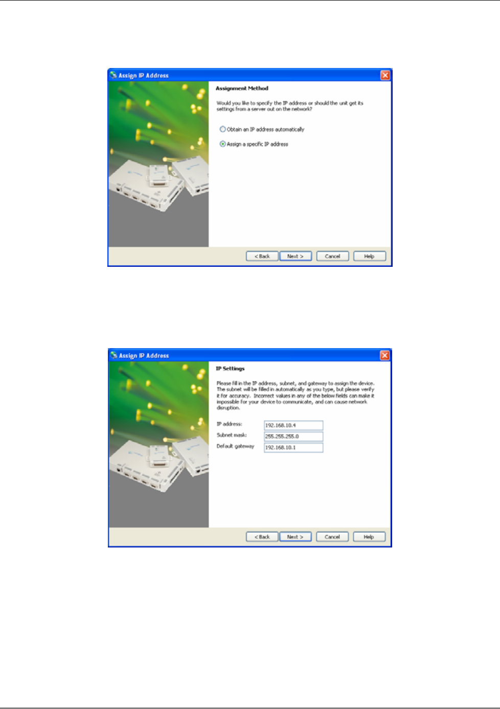
2. Click Next. The IP Address Assignment Method window appears.
Figure 4-7. Static IP Address
3. Select Assign a specific IP address; then, click Next. The IP Settings
window appears.
Figure 4-8. Static IP Address Definition

Remote - Web Browser Session
MA 850A1A1 Installation and Configuration Guide 32
4. Enter the IP Address, Subnet Mask and Default Gateway values; then,
click Next. The Assignment window appears.
Figure 4-9. Assignment Window
5. Click Assign to assign the MA 850A1 unit the defined parameters.
Once the parameters have been assigned, the message ‘Completed Successfully’ appears
and the Finish button is enabled.
Figure 4-10. Finish Static IP Address Definition
Remote - Web Browser Session
MA 850A1A1 Installation and Configuration Guide 33
6. Click Finish. The Device Installer Main window reappears and the
installed unit will be listed in the window.
What next?
Define the SNMP parameters according to Configuring the SNMP Parameters, page 33.
4.2.1.4 Configuring the SNMP Parameters
Configure the SNMP Community and Trap destination addresses according to the instructions in
this section.
NOTE: The required communication parameters are pre-set for each MA 850A1 unit. However if
you do not succeed in connecting to the Telnet application, verify the serial communication
parameter page 34 section
4.2.1.5
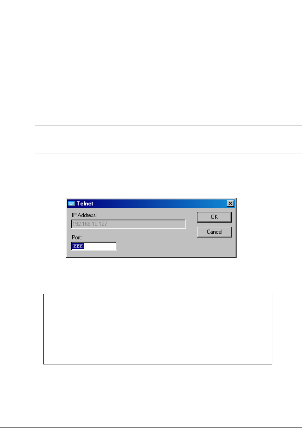
1. Select the MA 850A1 unit which will be configured (may be identified
according to its MAC address value) and click the Telnet button in the
toolbar.
The Telnet dialog shows the IP address of the currently connected MA 850A1 unit.
Figure 4-11. Telnet IP Address window
2. Click OK and immediately press Enter to go into Setup Mode. The current
settings will be displayed, followed by the Change Setup menu.
Change Setup:
0 Server configuration
1 Channel 1 configuration
3 SNMP configuration
7 factory defaults
8 exit without save
9 save and exit Your choice ?
3. Enter 3 (SNMP Configuration).
Remote - Web Browser Session
MA 850A1A1 Installation and Configuration Guide 34
4. Set the SNMP Read and Write community names and the SNMP traps destination addresses
(up to three addresses can be defined) by responding with Y to the prompt Set the
Gateway IP Address and defining the Address (as illustrated below).
SNMP community name for read (): public
SNMP community name for write (): private
Enter IP addresses for SNMP traps:
1: (000) 192.(000) 168.(000) 10.(000) 22
2: (000) .(000) .(000) .(000)
3: (000) .(000) .(000) .(000)
5. Press Enter to run through the rest of the parameters. When the Setup
Menu is displayed again, select 9 – Save and Exit.
4.2.1.5 Configuring Serial Parameters
This section describes how to verify and configure the serial communication parameters for each
MA 850A1 unit.
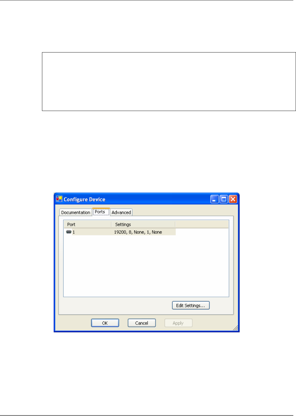
1. From the DeviceInstaller Main window, select the MA 850A1 unit to be configured and click
the Configure button the toolbar. The Configure Device dialog appears.
Figure 4-12. Current Serial Port Parameters
Remote - Web Browser Session
MA 850A1A1 Installation and Configuration Guide 35
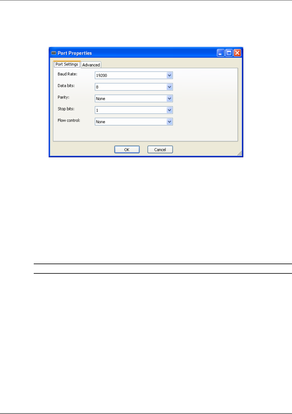
2. Click the Ports tab and then the Edit Settings… button. The Port Properties dialog
appears.
Figure 4-13. Port Properties
3. Set the parameters as follows: Baud Rate 19200, Data Bits 8, Parity None, Stop Bits 1, Flow
Control None; then, click OK. The DeviceInstaller Main window appears.
4.2.2 Login and User Levels
You may login to the MA 850A1 unit through any Web browser. Two user levels are available:
• guest (guestpass) – monitoring options only
• admin (adminpass) – monitoring and configuration options
NOTE: The password is case sensitive – use lower case letters.
To login to the MA 850A1 configuration application
1. Run a Web Browser application (i.e. Internet Explorer).
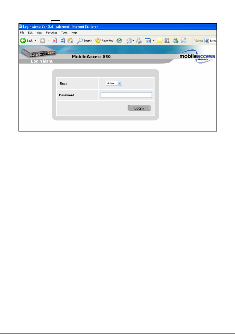
2. Enter the IP Address of the MA 850A1 unit. (i.e. http://192.168.10.127). The Login dialog
appears. The application version is displayed at the top of the window.
Remote - Web Browser Session
MA 850A1A1 Installation and Configuration Guide 36
Figure 4-14. Login Window
3. Select the User (guest or admin) and the password; where admin has
configuration privileges.
4. Click Login. The Main configuration window appears. The window shows the current
configuration (Active Configuration) and provides access to configuration and monitoring
options. The Main window is described in the following section.
Application Version
Remote - Web Browser Session
MA 850A1A1 Installation and Configuration Guide 37
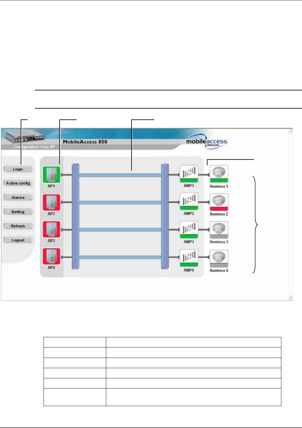
4.2.3 MA 850A1 View
Upon login, the MA 850A1 View shows the current 802.11b/g AP and antenna connections.
Menu options on the left side provide access to various configuration options as described in
Table 4-1. Element color indications is described in Table 4-2.
NOTE: The display is refreshed automatically; however, if necessary, be sure to use the
application Refresh button in the menu options (and not the Web Browser refresh).
Figure 4-15. Main Window
Table 4-1. MA 850A1 View Menu Options
Menu Option Description
Login/Logout Click to login using a different user level
Active config Displays the current configuration
Alarms Alarm monitoring
Refresh Used to refresh the display.
Setting Gain setting (default = 0) and Redundancy enable/disable
options
Menu
options
Access
Points
Antenna connection
routes
Internal
channels
Antenna
connection status

Gain Setting for 802.11b/g Channels
MA 850A1A1 Installation and Configuration Guide 38
Table 4-2. MA 850A1 View Color Indications
Option Description
Green OK
Red Error indication:
Red AP - an AP included in the current configuration is not
detected.
Red antenna – antenna not detected by antenna sense
mechanism
Red Amp – channel malfunction identified in the MA 850A1 unit
Purple Location (not status) of backup AP in one-AP or two-AP
configurations with in which the redundancy option is enabled.
Only if the backup AP is activated (upon failure of a default AP),
does its color indicate status (green, red).
Gray Not relevant in current configuration – whether an AP is
physically connected to the specific port or not.
4.3 Gain Setting for 802.11b/g Channels
The default gain for each 802.11b/g channel is set to 0dB. MA 850A1 enables the authorized
user (admin level) to adjust the gain for every channel to counteract changes in the
environment.
For example, you may want to reduce the coverage area of a channel to prevent interference.
Or, the output of an AP with a low power (<20dBm) can be increased using the gain value to a
maximum level of 20dBm.
Monitoring Alarms
MA 850A1A1 Installation and Configuration Guide 39
To change the gain setting of a channel
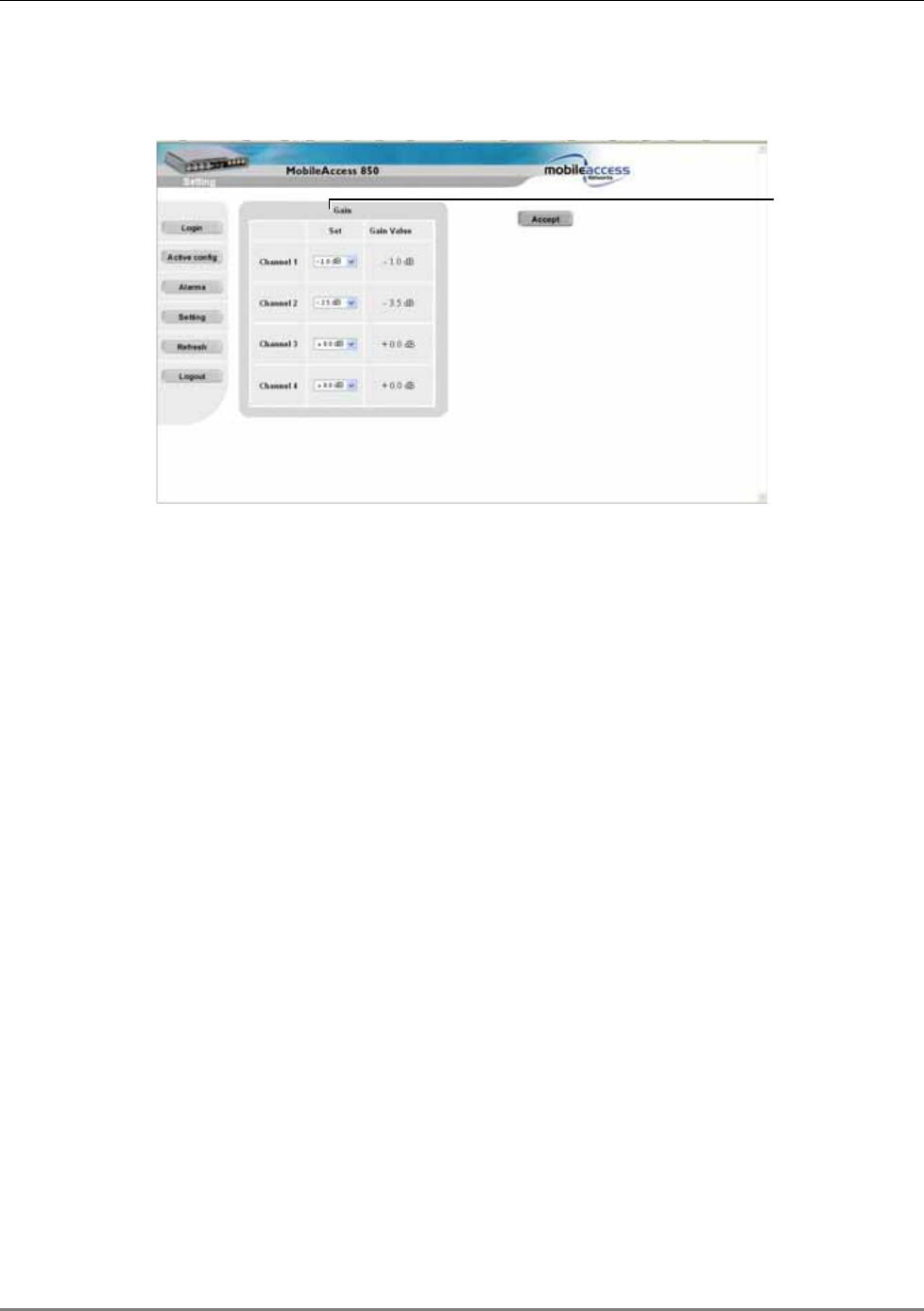
1. Click the Setting button in the Main window. The Gain Setting options appear.
Figure 4-16. Gain Setting Options
2. For the relevant channel, change the gain. Range = -10 to +5 dB
3. Click Accept. The gain value for the channels at the unit is displayed under
the Gain Value column.
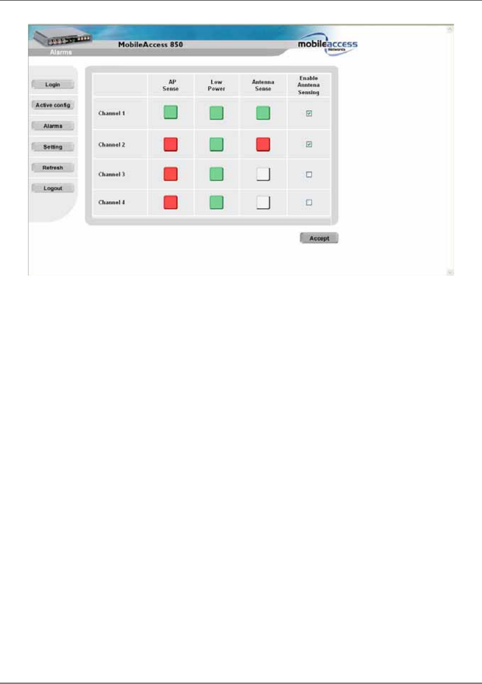
4.4 Monitoring Alarms
MA 850A1 provides the following alarms, which may be viewed by clicking the Alarms button in
the Main window:
• Access Point Sense – senses the connection of configured APs
• Low power – internal channel operation status
• Antenna sense – senses connected antennas. This option can be disabled for antennas
that are not connected
Gain Setting
options
Monitoring Alarms
MA 850A1A1 Installation and Configuration Guide 40
Figure 4-17. Alarms Window
MA 850A1A1 Installation and Configuration Guide 41
5
S
SN
NM
MP
P
M
Ma
an
na
ag
ge
em
me
en
nt
t
U
Us
si
in
ng
g
A
An
ny
y
S
St
ta
an
nd
da
ar
rd
d
S
SN
NM
MP
P
M
Ma
an
na
ag
ge
er
r
The MA 850A1 packages provide MIBSs that enable standard SNMP (Version 2.0) managers such
as HP OpenView to view event traps sent by the MA 850A1 unit and to configure the unit.
One MIB file is provided: MA-XPORT850-MIB– describes the architecture of the managed
elements and contains the events in the system
NOTE: These traps provide a general indication of the type of failure. The MA 850A1 enables
identifying the source of the problem and system monitoring parameters.
5.1 Traps List
NOTE: Traps are only sent to defined trap destinations (section
4.2.1.4).
The following traps are provided:
Table 5-1. List of MA 850A1 Traps
Name Type OID Description
x850SystemOnNotify NOTIFICATION-TYPE 90.4.2.0.1 System On.
x850SerialNotify
NOTIFICATION-TYPE 90.4.2.0.2 serial communication
status failed success
x850A1ntenaConnectedNotify NOTIFICATION-TYPE 90.4.2.0.3 Antenna Connected

Traps List
MA 850A1A1 Installation and Configuration Guide 42
Name Type OID Description
x850A1ntenaDisconnectedNotify NOTIFICATION-TYPE 90.4.2.0.4 Antenna Disconnected
x850OutPowerLowNotify NOTIFICATION-TYPE 90.4.2.0.5 Out Power Low
x850OutPowerNormalNotify NOTIFICATION-TYPE 90.4.2.0.6 Out Power Normal
x850A1PConnectedNotify NOTIFICATION-TYPE 90.4.2.0.7 AP Connected
x850A1PDisconnectedNotify NOTIFICATION-TYPE 90.4.2.0.8 AP Disconnected
x850A1MPRecoveredNotify NOTIFICATION-TYPE 90.4.2.0.11 AMP Recovered
x850A1MPFailedNotify NOTIFICATION-TYPE 90.4.2.0.12 AMP Failed
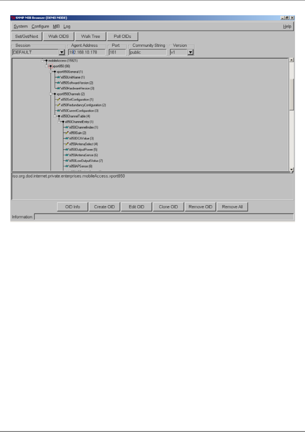
To view the traps using any standard SNMP manager
NOTE: It is assumed that the IP Address of at least one destination is already defined.
From a computer
configured as a trap destination
(configured to receive the traps), load the two
MIB files to the SNMP manager. The following figure shows the MIB tree that includes the
loaded MobileAccess 850 file.
Traps List
MA 850A1A1 Installation and Configuration Guide 43
Figure
5-1. MIB Tree with Loaded MobileAccess 850 Files