Corning Optical Communication MA860WCE-AU 860M-AU WITH WCE-AU User Manual
Corning Optical Communication Wireless 860M-AU WITH WCE-AU Users Manual
UserManual.wiki
>
Corning Optical Communication
>
MA860WCE AU User Manual
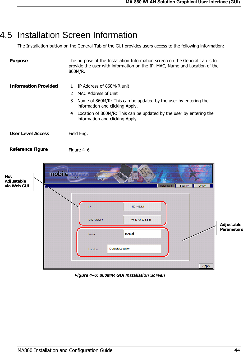
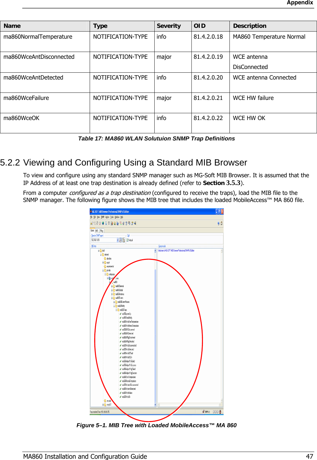
Users Manual
Navigation menu
Upload a User Manual
Namespaces
Wiki Guide
HTML
PDF
Info
Views
User Manual
Discussion / Help
Navigation