Corning Optical Communication MA860WCE-AU 860M-AU WITH WCE-AU User Manual
Corning Optical Communication Wireless 860M-AU WITH WCE-AU Users Manual
Users Manual

P/N: xxxxx
REV: A01
Date: MARCH-2009
MA-860 WLAN Solution
(MA-860 Module + WiFi Coverage
Expander)
Installation and Configuration
Manual

II
World Headquarters
MobileAccess™
8391 Old Courthouse Road, Suite 300
Vienna, Virginia 22182
USA
Tel: +1(866) 436-9266
TAC: +1(800) 787-1266
Fax: +1(703) 848-0280
Trademark Acknowledgement
© Copyright 2009, MobileAccess™ Networks Inc. All Rights Reserved.
MOBILEACCESS™TM IS A REGISTERED TRADEMARK OF MOBILEACCESS™. THIS DOCUMENT CONTAINS OTHER TRADEMARKS, TRADE
NAMES AND SERVICE MARKS OF MOBILEACCESS™ AND OTHER ORGANIZATIONS, ALL OF WHICH ARE THE PROPERTY OF THEIR
RESPECTIVE OWNERS.
THIS DOCUMENT CONTAINS CONFIDENTIAL AND PROPRIETARY INFORMATION OF MOBILEACCESS™ AND MAY NOT BE COPIED,
TRANSMITTED, STORED IN A RETRIEVAL SYSTEM OR REPRODUCED IN ANY FORMAT OR MEDIA, IN WHOLE OR IN PART, WITHOUT THE
PRIOR WRITTEN CONSENT OF MOBILEACCESS™. INFORMATION CONTAINED IN THIS DOCUMENT SUPERSEDES ANY PREVIOUS MANUALS,
GUIDES, SPECIFICATIONS, DATA SHEETS OR OTHER INFORMATION THAT MAY HAVE BEEN PROVIDED OR MADE AVAILABLE TO THE USER.
THIS DOCUMENT IS PROVIDED FOR INFORMATIONAL PURPOSES ONLY, AND MOBILEACCESS™ DOES NOT WARRANT OR GUARANTEE THE
ACCURACY, ADEQUACY, QUALITY, VALIDITY, COMPLETENESS OR SUITABILITY FOR ANY PURPOSE OF THE INFORMATION CONTAINED IN
THIS DOCUMENT. MOBILEACCESS™ RESERVES THE RIGHT TO MAKE UPDATES, IMPROVEMENTS AND ENHANCEMENTS TO THIS
DOCUMENT AND THE PRODUCTS TO WHICH IT RELATES AT ANY TIME WITHOUT PRIOR NOTICE TO THE USER. MOBILEACCESS™
MAKES NO WARRANTIES, EXPRESS OR IMPLIED, INCLUDING, WITHOUT LIMITATION, THOSE OF MERCHANTABILITY
AND FITNESS FOR A PARTICULAR PURPOSE, WITH RESPECT TO THIS DOCUMENT OR ANY INFORMATION
CONTAINED HEREIN.

III
Table of Contents
Preface .........................................................................................................................................................v
Policy for Warranty and Repair .............................................................................................................................v
Safety ................................................................................................................................................................ vi
Certification ....................................................................................................................................................... vii
Professional Installation of Transmitter ................................................................................................................viii
Additional Relevant Documents ........................................................................................................................... ix
List of Acronyms ................................................................................................................................................. ix
1 Introduction..........................................................................................................................................1
1.1 MobileAccess™ 860 WLAN Solution Overview ..............................................................................................1
1.2 Benefits.......................................................................................................................................................2
1.3 Deployment Options.....................................................................................................................................3
2 MA-860 WLAN Solution Components ...............................................................................................4
2.1 MA-860 WLAN Module (860M/R) ..................................................................................................................4
2.1.1 Purpose ............................................................................................................................................4
2.1.2 Front Panel Interfaces and Indicator LEDs ..........................................................................................5
2.1.3 Rear Panel Interfaces and Indicator LEDs...........................................................................................6
2.2 WCE ...........................................................................................................................................................7
2.2.1 Purpose ............................................................................................................................................7
2.2.2 WCE Interfaces, Mounting Support, and LEDs ....................................................................................8
3 Installation Guidelines......................................................................................................................10
3.1 MA-860 WLAN Installation Procedure..........................................................................................................10
3.2 Coax Cable Connectivity Guidelines............................................................................................................11
3.3 Wi-Fi Coverage Expander (WCE)................................................................................................................12
3.3.1 WCE Connection to 860M/R.............................................................................................................12
3.3.2 WCE Mounting ................................................................................................................................12
3.4 Installation and Mounting Installation and Mounting 860M/R .........................................................................14
3.4.1 General 860M/R Installation Guidelines ............................................................................................14
3.4.2 Mounting and Accessory Kits ...........................................................................................................15
3.4.3 Rack mounted.................................................................................................................................16
3.4.4 Wall mounted ..................................................................................................................................17
3.4.5 Stacked ..........................................................................................................................................18
3.5 Configuring Network Parameters.................................................................................................................27
3.5.1 Default Settings...............................................................................................................................27
3.5.2 Changing the Network Settings.........................................................................................................27

Table of Contents
MA860 Installation and Configuration Guide IV
3.5.3 Setting SNMP Parameters ...............................................................................................................29
3.6 Power Consumption and Power Supplies ....................................................................................................31
3.6.1 Power Safety Instructions.................................................................................................................31
3.6.2 Input Power Requirements ...............................................................................................................31
3.6.3 MobileAccess™ Supplied Power Supplies.........................................................................................32
3.6.4 Connecting Power Supply to the MA-860 WLAN Solution...................................................................32
3.7 MobileAccess™ Supported Multi Service Antennas......................................................................................33
3.8 Access Points ............................................................................................................................................33
3.8.1 Approved APs .................................................................................................................................33
3.8.2 AP Connection and Configuration with MA-860..................................................................................34
3.8.3 AP Installation in IDF or Telecom Closet ...........................................................................................35
4 MA-860 WLAN Solution Graphical User Interface (GUI)................................................................36
4.1 Accessing the GUI .....................................................................................................................................36
4.2 Login and User Account Levels...................................................................................................................37
4.3 MA-860 GUI Control Information .................................................................................................................38
4.3.1 General Tab Information ..................................................................................................................38
4.3.2 Adjustments Tab Information............................................................................................................39
4.3.3 Alarms Tab Information....................................................................................................................41
4.4 Security Screen Information........................................................................................................................43
4.5 Installation Screen Information....................................................................................................................44
5 Appendix ............................................................................................................................................45
5.1 MA-860 Cable Compensation Feature.........................................................................................................45
5.2 SNMP Management Using a Standard SNMP Manager................................................................................45
5.2.1 Traps List........................................................................................................................................46
5.2.2 Viewing and Configuring Using a Standard MIB Browser....................................................................47
5.3 860M/R Network Configuration Recovery Procedure ....................................................................................48
5.4 NMS Management and Configuration..........................................................................................................49

Preface Material
MA860 Installation and Configuration Guide v
P
Pr
re
ef
fa
ac
ce
e
Policy for Warranty and Repair
MOBILEACCESS™ TESTS AND INSPECTS ALL ITS PRODUCTS TO VERIFY THEIR QUALITY AND RELIABILITY. MOBILEACCESS™ USES EVERY
REASONABLE PRECAUTION TO ENSURE THAT EACH UNIT MEETS THEIR DECLARED SPECIFICATIONS BEFORE SHIPMENT. CUSTOMERS
SHOULD ADVISE THEIR INCOMING INSPECTION, ASSEMBLY, AND TEST PERSONNEL ABOUT THE PRECAUTIONS REQUIRED IN HANDLING
AND TESTING OUR PRODUCTS. MANY OF THESE PRECAUTIONS CAN BE FOUND IN THIS MANUAL.
THE PRODUCTS ARE COVERED BY THE FOLLOWING WARRANTIES:
General Warranty
MOBILEACCESS™ WARRANTS TO THE ORIGINAL PURCHASER ALL STANDARD PRODUCTS SOLD BY MOBILEACCESS™ TO BE FREE OF
DEFECTS IN MATERIAL AND WORKMANSHIP FOR ONE (1) YEAR FROM DATE OF SHIPMENT FROM MOBILEACCESS™. DURING THE
WARRANTY PERIOD, MOBILEACCESS™ WILL REPAIR OR REPLACE ANY PRODUCT THAT MOBILEACCESS™ PROVES TO BE DEFECTIVE.
THIS WARRANTY DOES NOT APPLY TO ANY PRODUCT THAT HAS BEEN SUBJECT TO ALTERATION, ABUSE, IMPROPER INSTALLATION OR
APPLICATION, ACCIDENT, ELECTRICAL OR ENVIRONMENTAL OVER-STRESS, NEGLIGENCE IN USE, STORAGE, TRANSPORTATION OR
HANDLING.
Specific Product Warranty Instructions
ALL MOBILEACCESS™ PRODUCTS ARE WARRANTED AGAINST DEFECTS IN WORKMANSHIP, MATERIALS AND CONSTRUCTION, AND TO NO
FURTHER EXTENT. ANY CLAIM FOR REPAIR OR REPLACEMENT OF UNITS FOUND TO BE DEFECTIVE ON INCOMING INSPECTION BY A
CUSTOMER MUST BE MADE WITHIN 30 DAYS OF RECEIPT OF SHIPMENT, OR WITHIN 30 DAYS OF DISCOVERY OF A DEFECT WITHIN THE
WARRANTY PERIOD.
THIS WARRANTY IS THE ONLY WARRANTY MADE BY MOBILEACCESS™ AND IS IN LIEU OF ALL OTHER WARRANTIES, EXPRESSED OR
IMPLIED. MOBILEACCESS™ SALES AGENTS OR REPRESENTATIVES ARE NOT AUTHORIZED TO MAKE COMMITMENTS ON WARRANTY
RETURNS.
Returns
IN THE EVENT THAT IT IS NECESSARY TO RETURN ANY PRODUCT AGAINST ABOVE WARRANTY, THE FOLLOWING PROCEDURE SHALL BE
FOLLOWED:
1. RETURN AUTHORIZATION IS TO BE RECEIVED FROM MOBILEACCESS™ PRIOR TO RETURNING ANY UNIT. ADVISE MOBILEACCESS™ OF
THE MODEL, SERIAL NUMBER, AND DISCREPANCY. THE UNIT MAY THEN BE FORWARDED TO MOBILEACCESS™, TRANSPORTATION
PREPAID. DEVICES RETURNED COLLECT OR WITHOUT AUTHORIZATION MAY NOT BE ACCEPTED.
2. PRIOR TO REPAIR, MOBILEACCESS™ WILL ADVISE THE CUSTOMER OF OUR TEST RESULTS AND ANY CHARGES FOR REPAIRING
CUSTOMER-CAUSED PROBLEMS OR OUT-OF-WARRANTY CONDITIONS ETC.
3. REPAIRED PRODUCTS ARE WARRANTED FOR THE BALANCE OF THE ORIGINAL WARRANTY PERIOD, OR AT LEAST 90 DAYS FROM DATE
OF SHIPMENT.
Limitations of Liabilities
MOBILEACCESS™'S LIABILITY ON ANY CLAIM, OF ANY KIND, INCLUDING NEGLIGENCE FOR ANY LOSS OR DAMAGE ARISING FROM,
CONNECTED WITH, OR RESULTING FROM THE PURCHASE ORDER, CONTRACT, QUOTATION, OR FROM THE PERFORMANCE OR BREACH
THEREOF, OR FROM THE DESIGN, MANUFACTURE, SALE, DELIVERY, INSTALLATION, INSPECTION, OPERATION OR USE OF ANY EQUIPMENT
COVERED BY OR FURNISHED UNDER THIS CONTACT, SHALL IN NO CASE EXCEED THE PURCHASE PRICE OF THE DEVICE WHICH GIVES RISE
TO THE CLAIM.
EXCEPT AS EXPRESSLY PROVIDED HEREIN, MOBILEACCESS™ MAKES NO WARRANTY, EXPRESSED OR IMPLIED,
WITH RESPECT TO ANY GOODS, PARTS AND SERVICES PROVIDED IN CONNECTION WITH THIS AGREEMENT
INCLUDING, BUT NOT LIMITED TO, THE IMPLIED WARRANTIES OF MERCHANTABILITY AND FITNESS FOR A
PARTICULAR PURPOSE. MOBILEACCESS™ SHALL NOT BE LIABLE FOR ANY OTHER DAMAGE INCLUDING, BUT NOT
LIMITED TO, INDIRECT, SPECIAL OR CONSEQUENTIAL DAMAGES ARISING OUT OF OR IN CONNECTION WITH
FURNISHING OF GOODS, PARTS AND SERVICE HEREUNDER, OR THE PERFORMANCE, USE OF, OR INABILITY TO
USE THE GOODS, PARTS AND SERVICE.
Preface Material
MA860 Installation and Configuration Guide vi
Reporting Defects
THE UNITS WERE INSPECTED BEFORE SHIPMENT AND FOUND TO BE FREE OF MECHANICAL AND ELECTRICAL DEFECTS.
EXAMINE THE UNITS FOR ANY DAMAGE THAT MAY HAVE BEEN CAUSED IN TRANSIT. IF DAMAGE IS DISCOVERED, FILE A CLAIM WITH THE
FREIGHT CARRIER IMMEDIATELY. NOTIFY MOBILEACCESS™ AS SOON AS POSSIBLE.
NOTE: KEEP ALL PACKING MATERIAL UNTIL YOU HAVE COMPLETED THE INSPECTION
WARNING: TO COMPLY WITH FCC RF EXPOSURE COMPLIANCE REQUIREMENTS, ANTENNAS USED FOR THIS PRODUCT MUST BE FIXED
MOUNTED ON INDOOR PERMANENT STRUCTURES, PROVIDING A SEPARATION DISTANCE OF AT LEAST 20 CM FROM ALL PERSONS DURING
NORMAL OPERATION.
WARNING: ANTENNA GAIN SHOULD NOT EXCEED 7DBI (REFER TO SECTION 3.4.1 FOR FURTHER INFORMATION).
WARNING: EACH INDIVIDUAL ANTENNA USED FOR THIS TRANSMITTER MUST BE INSTALLED TO PROVIDE A MINIMUM SEPARATION
DISTANCE OF 20 CM OR MORE FROM ALL PERSONS AND MUST NOT BE CO-LOCATED WITH ANY OTHER ANTENNA FOR MEETING RF
EXPOSURE REQUIREMENTS.
WARNING: THE DESIGN OF THE ANTENNA INSTALLATION NEEDS TO BE IMPLEMENTED IN SUCH A WAY SO AS TO ENSURE RF RADIATION
SAFETY LEVELS AND NON-ENVIRONMENTAL POLLUTION DURING OPERATION.
ATTENTION:
COMPLIANCE WITH RF SAFETY REQUIREMENTS:
MOBILEACCESS™ PRODUCTS HAVE NO INHERENT SIGNIFICANT RF RADIATION.
THE RF LEVEL ON THE DOWN LINK IS VERY LOW AT THE DOWNLINK PORTS. THEREFORE, THERE IS NO DANGEROUS RF RADIATION WHEN
THE ANTENNA IS NOT CONNECTED.
Safety
WARNING! To comply with FCC RF exposure compliance requirements, antennas used for
this product must be fixed mounted on indoor permanent structures, providing a separation
distance of at least
20 cm from all persons during normal operation.
Each individual antenna used for this transmitter must be installed to provide a minimum
separation distance of 20 cm or more from all persons and must not be co-located with any
other antenna for meeting RF exposure requirements.
The design of the antenna installation needs to be implemented in such a way so as to ensure
RF radiation safety levels and non-environmental pollution during operation.
Compliance with RF safety requirements:
• MobileAccess™ products have no inherent significant RF radiation.
• The RF level on the downlink is very low at the downlink ports. Therefore, there is no dangerous RF
radiation when the antenna is not connected.
Preface Material
MA860 Installation and Configuration Guide vii
Certification
MA-860 WLAN Solution (MA-860 module with WCE) has met the approvals of the following certifying
organizations:
• UL / IEC 60950 -1
• UL2043 Fire/Plenum (WCE)
• CE EN 60950
• CAN/CSA C22.2 No 60950
• FCC–47, CFR 15.109, Part 15 Sections B, C, and E
Company Certification
• ISO ISO 9001: 2000 and ISO 13485: 2003
Mean Time Before Failure (MTBF)
ProductFail RateMTBF (Hours)MTBF (Years)Temperature
860M/R-AU2.44409565.494750 deg C || 122 deg F
WCE-AU2.74360509.0044.550 deg C || 122 deg F
Table 1 - MTBF Data

Preface Material
MA860 Installation and Configuration Guide viii
Professional Installation of Transmitter
According to FCC 15.203, if an intentional radiator has a standard antenna connector, it must be professionally
installed according to FCC 15.203 regulations.
In addition, the following also demonstrates compliance with Section 15.204(d), (i):
1. The MA-860 WLAN solution cannot be sold to the general public. It is only marketed and sold by authorized
agents. Only professional installation qualified ("licensed") by MobileAccess™ for this purpose is allowed to install
the MA-860 WLAN Solution.
2. The installation must be controlled and follow the requirement of "Installation Manual"
(
P/N:709C002901
). Each potential installer must receive special training, which is a condition for receiving the
license from MobileAccess™ Inc to become a "licensed" installer. The installation procedure as described in the
"Installation Manual" includes the mechanical installation and initial setup by a PC based tool.
3. The intended application of the system is exclusively for the commercial/industry use.

Preface Material
MA860 Installation and Configuration Guide ix
Document Purpose
This document serves as a guide to provide essential product functionality with all the information necessary to
professionally install and configure the MobileAccess™ MA-860 WLAN Solution. The MA-860 WLAN Solution is
comprised of the MA-860 WLAN Module (P/N 860M/R or 860R) and the WiFi Coverage Expander (P/N WCE)
units.
In this Installation and Configuration Manual, the product 860M/R and 860R shall be referred to as 860M/R. The
860M/R with WCE shall be referred to as the MA-860 or MA-860 WLAN Solution.
Additional Relevant Documents
• MobileAccess™ NMS 410/430 System
• MobileAccess™ 1000M Installation and Configuration Guide
• MobileAccess™ 860 SW Upgrade Procedure
List of Acronyms
802.11a WLAN IEEE Standard for 5GHz ISM band
802.11b/g WLAN IEEE Standard for 2.4GHz ISM band
AGC Automatic Gain Control
AP Access Point
ARM Adaptive Radio Management
BDA Bi-Directional Amplifier
BU Base Unit
DAS
DFS
Distributed Antenna System
Dynamic Frequency Selection
DL Downlink
ETL Electrical Safety Testing Organization
FCC Federal Communications Commission
GUI Graphical User Interface
HTTP Hypertext Transfer Protocol
IEEE Institute of Electrical and Electronic Engineering
IP Internet Protocol Address
LBS Location Based Services
LWAPP Light Weight Access Point Protocol
LED Light Emission Diode
MA-860
860M/R
860R
PSU
MobileAccess™ WLAN solution that includes the 860M/R and the WCE
MobileAccess™ WLAN module without redundant power supply.
MobileAccess™ WLAN module with redundant power supply.
Power Supply Unit
RHU Remote Hub Unit
RP Reverse polarity

Preface Material
MA860 Installation and Configuration Guide x
RRM Radio Resource Management
RTLS Real Time Location Systems
SCU Splitting and Combining Unit
SMA A coaxial connector (Subminiture Version A)
SNMP Simple Network Management Protocol
SNR Signal to Noise Ratio
TNC (Threaded Neill-concelman) Connector
Type-N Threaded RF type N connector for coaxial cable
UL Uplink
VoIP Voice over Internet Protocol
VoWLAN
WCE
Voice over WLAN
WiFi Coverage Expander
WiFi Interoperability of WLAN products based on the IEEE 802.11 standards
WLAN Wireless Local Area Network
Introduction
MA860 Installation and Configuration Guide 1
1 I
In
nt
tr
ro
od
du
uc
ct
ti
io
on
n
The MobileAccess™ 860 WLAN Solution delivers pervasive WLAN coverage throughout enterprise environments
using a unique multi-service wireless architecture. With the MA-860 approach, enterprises can seamlessly
translate their WLAN investments and design expertise into a comprehensive, multi-service wireless solution.
This section summarizes the benefits and characteristics of the MobileAccess™ 860 WLAN Solution (MA-860).
1.1 MobileAccess™ 860 WLAN Solution Overview
The MA-860 WLAN Solution (MA-860) is part of the MobileAccess™ third generation family of products for the
Wireless LAN infrastructure. It is comprised of an MobileAccess™ 860 WLAN module (860M/R) and WiFi
Coverage Expanders (WCE). The MA-860 WLAN Solution provides a centralized, secure Wi-Fi AP management
system with greater range and coverage visibility by delivering an “AP-on-Ceiling” behavior and performance
with added benefits of security, management, and aesthetics across a single infrastructure to provide a complete
set of wireless services.
The MobileAccess™ 860 WLAN solution can leverage a single antenna infrastructure to deliver IEEE 802.11a and
802.11b/g WLAN solution. The MA-860 provides a combined services approach that allows the customer the
flexibility to choose one or all MobileAccess™ supported RF technologies for distribution over a single antenna
infrastructure: WLAN, Cellular/PCS, paging and/or public safety while maintaining a reliable application
independent architecture.
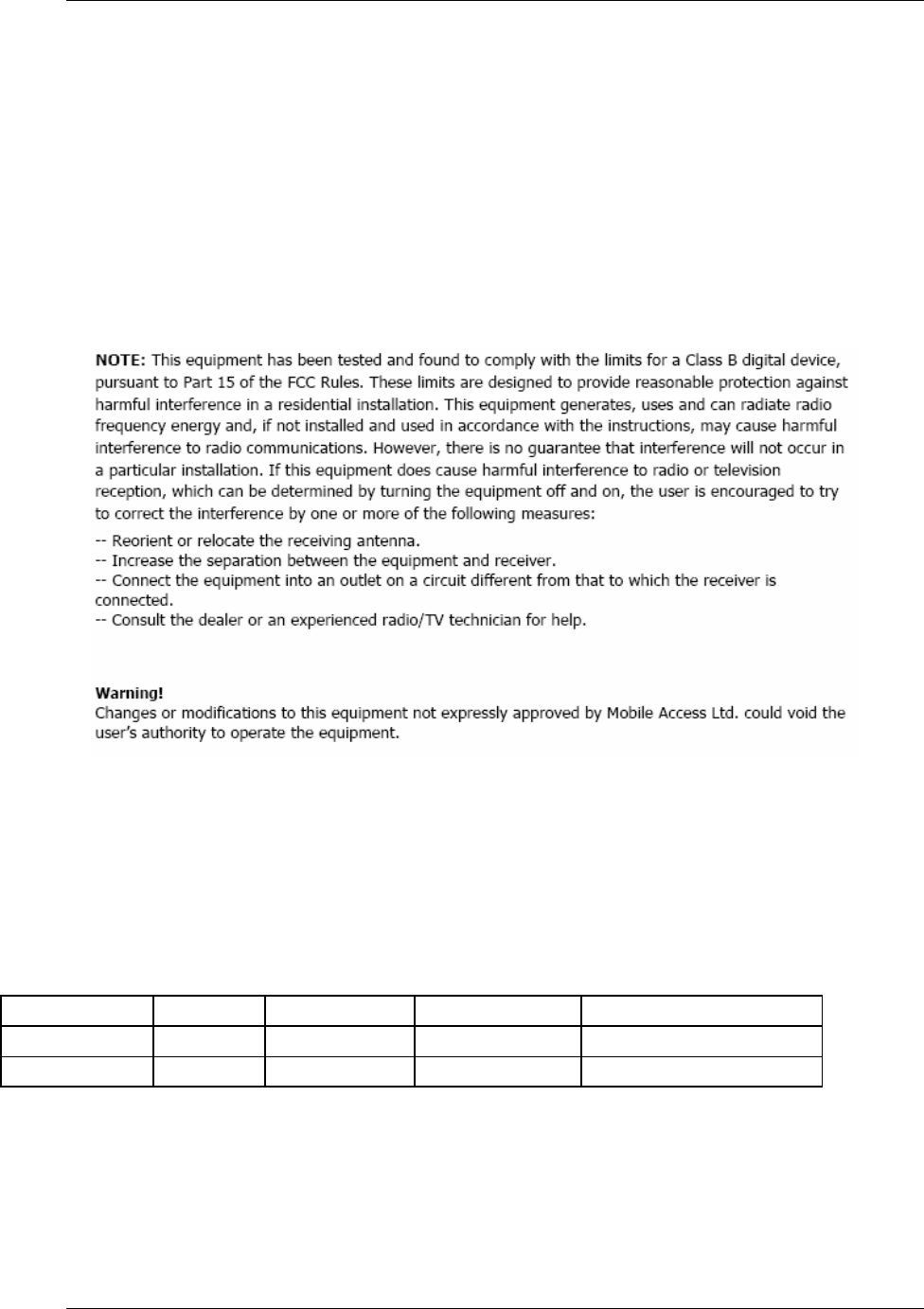
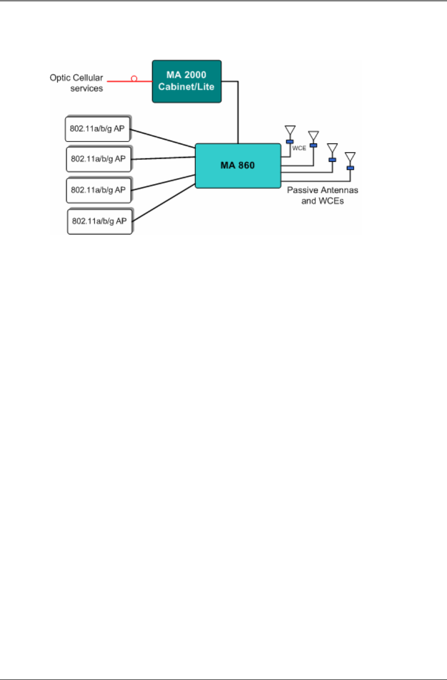
Figure 1–1: 860 WLAN Solution System Block Diagram provides an overview of how the MA-860 WLAN
solution interfaces with the rest of the MobileAccess™ portfolio of modules supporting Mobile Services
(Cellular/PCS, paging and/or public safety) and user provided WLAN Access Points for WLAN to provide multi-
service wireless services.
Figure 1–1: 860 WLAN Solution System Block Diagram

Introduction
MA860 Installation and Configuration Guide 2
1.2 Benefits
The following benefits are achieved with the MA-860 WLAN Solution:
Cost-Effective Multi-Service Solution
• Delivers WLAN and other wireless RF signals over a single multi-service infrastructure
• Spreads WLAN deployment costs across multiple wireless services
Dependable WLAN Coverage
• MobileAccess™ WLAN architecture mirrors the behaviors and coverage footprint of “AP-on-Ceiling”
deployment
• One-Click compensation between the 860M/R and WCE ensures optimal 802.11b/g and 802.11a
coverage
• Dedicated AP to antenna relationships ensure transparent support for WLAN applications such as VOIP
and location services (RTLS)
• Redundant power option
Centralized & Secure AP Management
• Lowers operating expenses
• Provides physical security and simplifies management
Proactive End-to-End Monitoring
• Remote SNMP monitoring for status, alerting, and fault detection
• Monitoring extends to attached multi-service antennas
Simplified IT Deployment Model
• Uses standard WLAN design techniques
Introduction
MA860 Installation and Configuration Guide 3
1.3 Deployment Options
The core feature set of the MobileAccess™ WLAN Solution includes the MA-860 WLAN module (860M/R) and
WiFi Coverage Expander (WCE).
The WLAN core feature set is currently deployable in the following configurations:
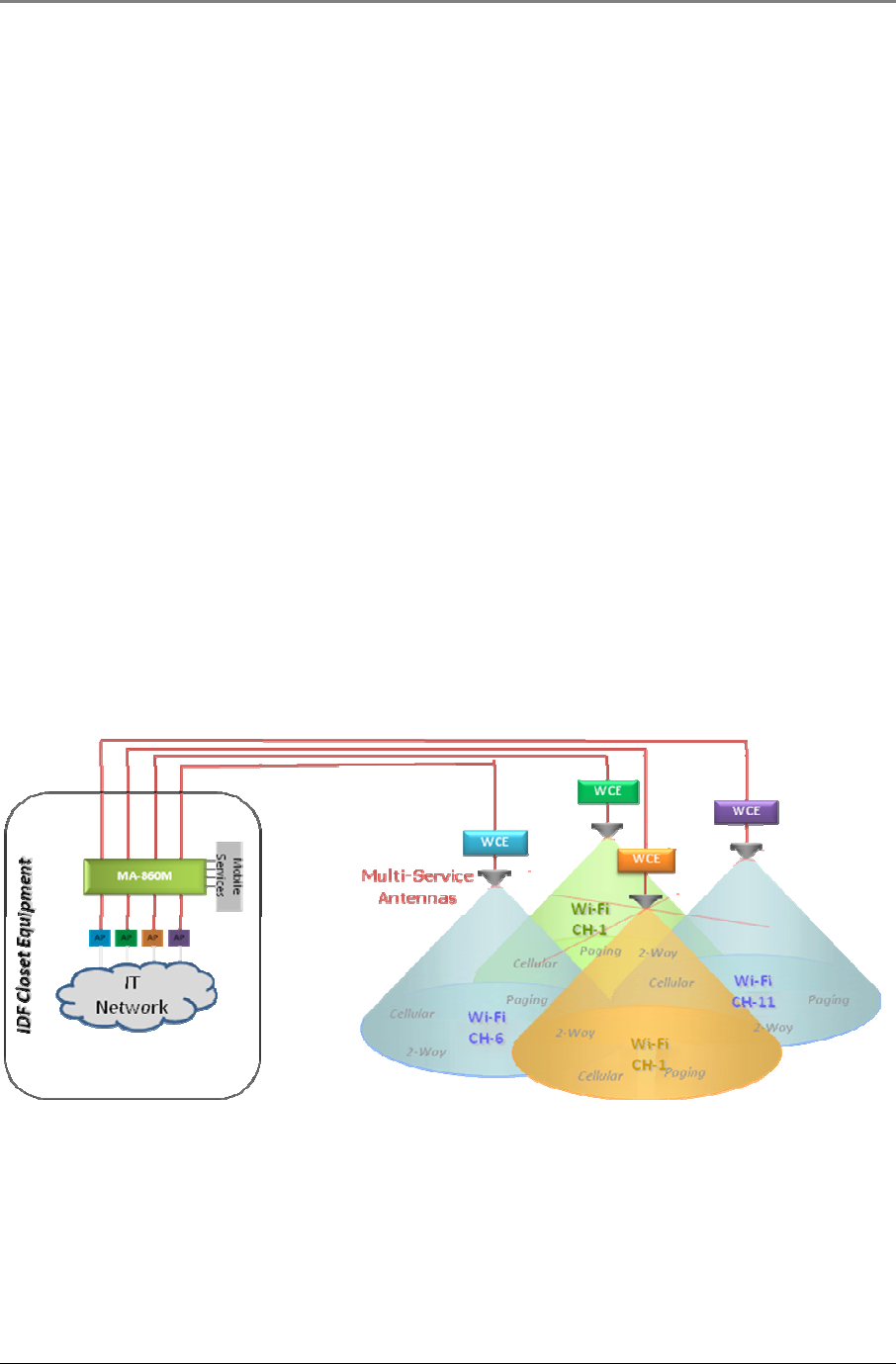
• 860M/R, WCE and Multi-service antennas: Deployed for WLAN coverage support only. Refer to Figure
1–2: MA-860 WLAN Solution for WLAN Coverage Only below:
Figure 1–2: MA-860 WLAN Solution for WLAN Coverage Only Block Diagram
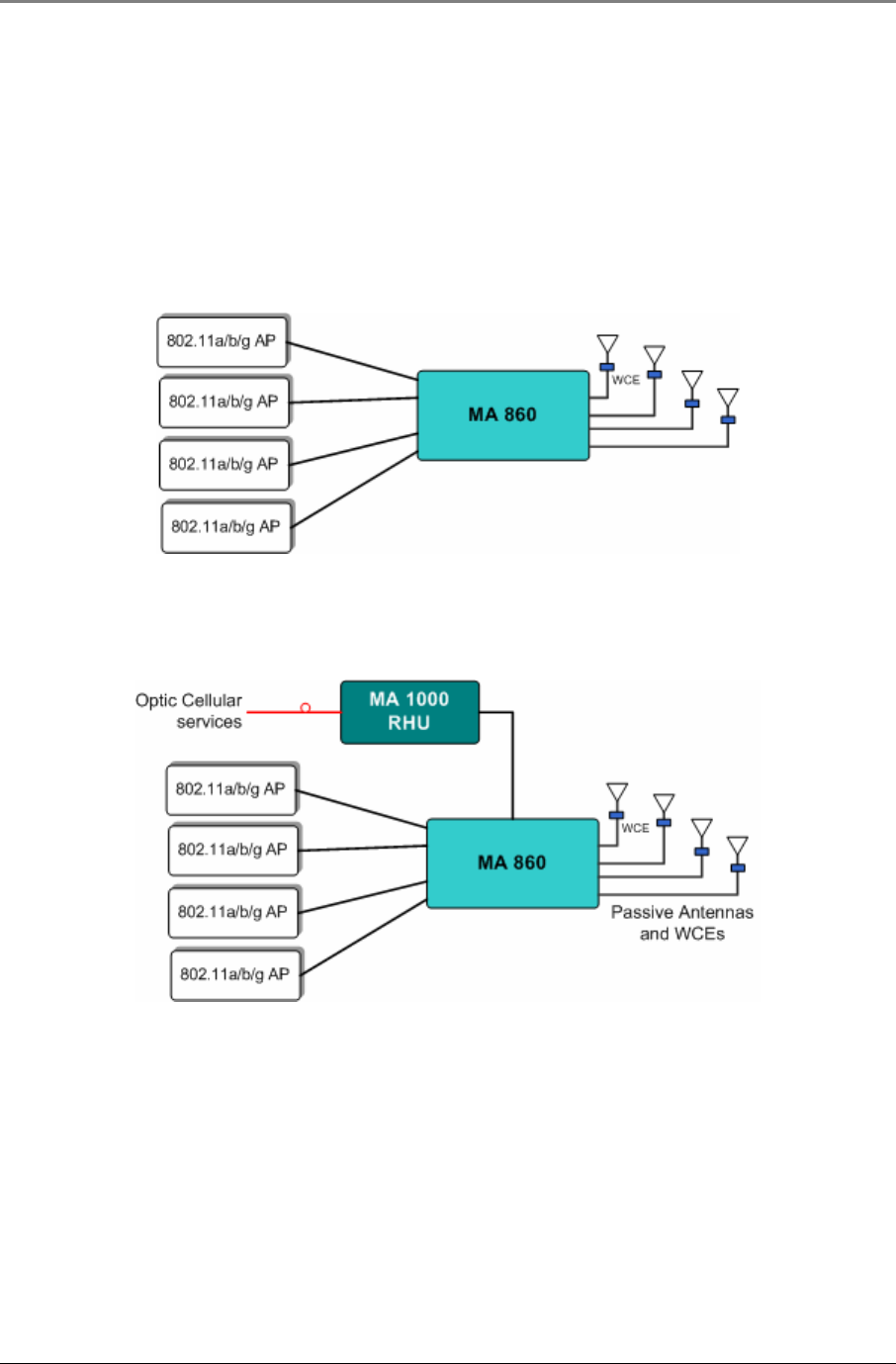
• 860M/R, WCE, Multi-service antennas, MA-1000 Remote Hub Units (RHUs): Deployed for WLAN and
Mobile Service coverage support. Refer to Figure 1–3: MA-860 WLAN Solution with MA-1000 for
WLAN and Mobile Service Coverage below.
Figure 1–3: MA-860 WLAN Solution with MA-1000 for WLAN and Mobile Service Coverage Block Diagram
MA-860 WLAN Solution Components
MA860 Installation and Configuration Guide 4
• 860M/R, WCE, Multi-service antennas and MA-2000 Remote Unit: Deployed for WLAN and Mobile
Service coverage support. Refer to Figure 1–4: MA-860 WLAN Solution with MA-2000 for
WLAN and Mobile Service Coverage below.
Figure 1–4: MA-860 WLAN Solution with MA-2000 for WLAN and Mobile Service Coverage Block Diagram
2 M
MA
A-
-8
86
60
0
W
WL
LA
AN
N
S
So
ol
lu
ut
ti
io
on
n
C
Co
om
mp
po
on
ne
en
nt
ts
s
The MA-860 WLAN Solution consists of the MA-860 WLAN module (860M/R) and the WiFi Coverage Expander
(WCE) unit. Both of these devices are required to provide full IEEE 802.11a/b/g WLAN coverage.
This section provides information on the technology and features of the 860M/R and WCE.
2.1 MA-860 WLAN Module (860M/R)
2.1.1 Purpose
The 860M/R is an active module installed in the remote closet that interfaces to several horizontal coaxial
antenna cables and to WiFi access points (APs) and Remote Hub Units (RHUs) in the IDF or telecom closet via
coax jumpers. It performs combining, RF switching and amplification of WiFi signals in the 802.11b/g (ISM2400)
and 802.11a (U-NII) frequency bands. The MA-860-HU also performs passive RF combining of Mobile Service
frequency bands (Cellular, PCS, Paging, 2-Way Radio, etc.).
The 860M/R interfaces to the antenna cables, combines the 802.11a/b/g and other RF signals for distribution
over broadband antennas.
The 860M/R provides:
• Support for up to four 802.11b/g access points (APs)
• Support for up to four 802.11a access points (APs)
• Support for up to four Mobile Service RHU modules or one Mobile Service Remote Cabinet
• Support for up to four WiFi Coverage Expanders (WCEs)
• Power for up to four WiFi Coverage Expanders (WCEs)
• Redundant DC connectivity sensing for all passive broadband antennas
MA-860 WLAN Solution Components
MA860 Installation and Configuration Guide 5
• Downlink (DL) power detection to support cable loss compensation functionality for WiFi that minimizes
impact of cable losses on the AP coverage radius
• Configuration support and status monitoring for WCEs
• Ethernet based local and remote configuration and monitoring
• Ethernet port for SNMP and HTTP based communications to support configuration and status
monitoring
• Mobile Access (MA) device interface to communicate antenna sense information to Cellular and/or
WMTS Remote Hub Units (RHUs)
The 860M/R enables clustering of the active APs in the IDF or telecom closets, providing a more secure and cost
effective infrastructure.
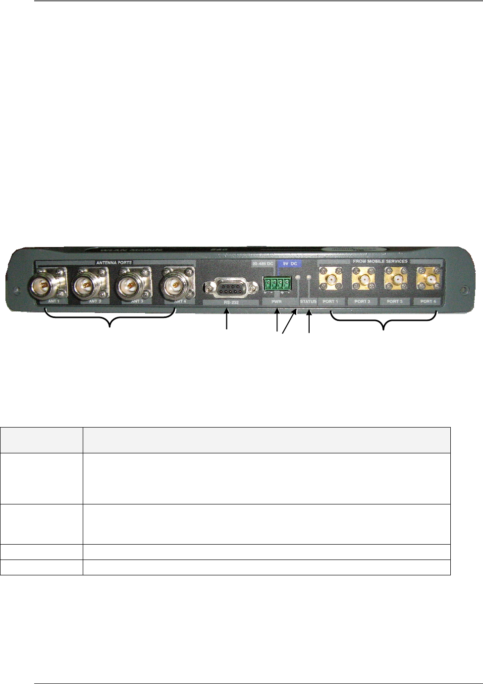
2.1.2 Front Panel Interfaces and Indicator LEDs
The front panel contains the antenna interface ports and mobile services ports, redundant power inputs, status
indicators, and local RS232 Console Port for local management. The following figure shows the 860M/R front
panel display.
Figure 2–1: MA-860 Front Panel
2.1.2.1 860M/R Front Panel Interfaces
The following table describes the front panel ports.
Front Panel
Ports Description
ANTENNA PORTS
ANT 1- ANT 4
Four N-type female connections. These connections are terminated at a WCE via ½” coax
which is then connected to a MobileAccess™ certified multi-service antenna via a jumper
cable.
NOTE: To be terminated with 50 ohm terminations when not in use.
FROM MOBILE
SERVICES PORT
1- PORT 4
Four SMA female connections used in installations that integrate MA-860 WLAN Solution
with MA 1000 RHUs or MA 2000 Remote Cabinet.
NOTE: To be terminated with 50 ohm terminations when not in use.
RS-232 RS232 Console Port connection is for field engineers to use during software upgrades.
PWR Power connection to Main and an optional Redundant power supply
Table 2: 860M/R Front Panel Ports
From Mobile Service
Ports 1-4
PWR
(Power)
Status
RS-232
Console Port
Antenna Ports
1-4
MA-860 WLAN Solution Components
MA860 Installation and Configuration Guide 6
2.1.2.2 860M/R Front Panel Indicator LEDs
The front panel contains two LEDs, described in the following table:
Front Panel LEDs Description
Status Internal operation and channel operation status:
Constant Green – unit performing antenna auto-discovery. This happens
automatically upon power-up and booting up of the 860M/R and WCE.
Green blinking – Auto-discovery completed and the WCE and 860M/R is
operational.
Off – If power is supplied (i.e. PWR Status LED is Constant Green) then
there is a fault detected in unit. Else, power is not supplied to the unit.
PWR Constant Green – Power OK.
Off – no power supplied to the unit.
Table 3: 860M/R Front Panel Indicator LEDs
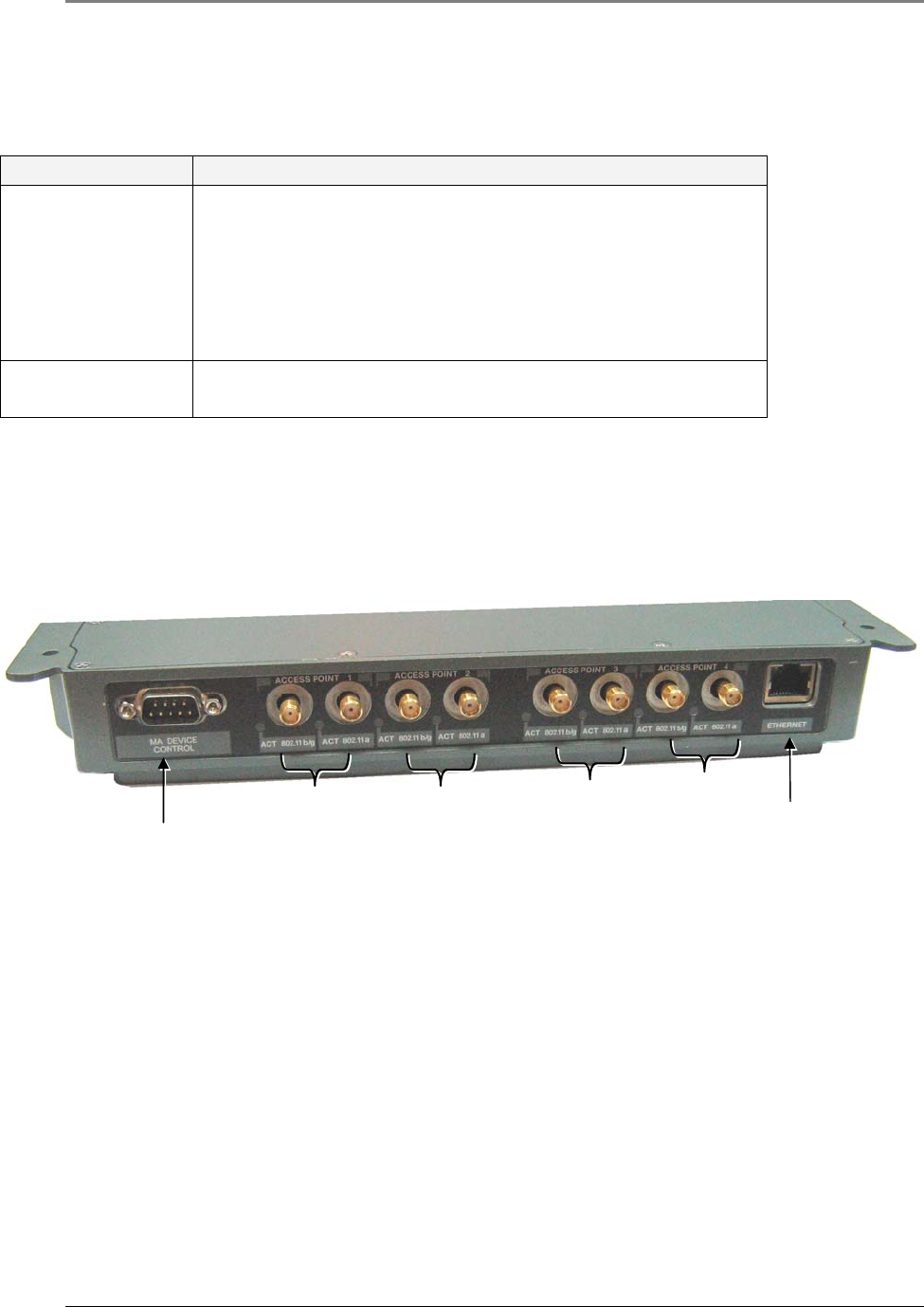
2.1.3 Rear Panel Interfaces and Indicator LEDs
The rear panel contains the following interfaces: four 802.11a/b/g Access Point input ports, RJ45
Ethernet port for remote management, and an antenna sensing connector.
Figure 2–2: 860M/R Rear Panel
Ethernet
802.11a/b/
g AP4
802.11a/
bgAP3
802.11a/b
/gAP2
802.11a/b
/gAP1
Antenna sensing
Add-on connector

MA-860 WLAN Solution Components
MA860 Installation and Configuration Guide 7
2.1.3.1 860M/R Rear Panel Interfaces
The following table describes the rear panel port interfaces:
Rear Panel Ports Description
802.11b/g AP1…AP4 Four APs 802.11b/g input SMA female connections.
NOTE: To be terminated with 50 ohm terminations when not in use.
802.11a AP1..AP4 Four APs 802.11a input SNA female connections.
NOTE: To be terminated with 50 ohm terminations when not in use.
MA Device Control
(Antenna Sensing)
Relevant only when 860M/R is converged with another MA system
remote unit (RHU 1000, RHU WiMAX. Connects to RHU 1000 rear
panel Control connector. Routes the antenna sensing (indication
of whether antenna is present) to the RHU for monitoring via the
management application. (RHU Version 3.1 and higher).
Ethernet port Connection to network for remote configuration and management
via any standard MobileAccess™ supported WEB browser.
Table 4: 860M/R Rear Panel Port Interfaces
2.1.3.2 860M/R Rear Panel Indicator LEDs
The rear panel LEDs indicate the status of the corresponding 802.11a/b/g AP:
Rear Panel LEDs Description
Blinking Green APs are physically connected and transmitting signals greater
than -6dBm.
Constant Green APs are physically connected, transmitting signals greater than -
6dBm and cable compensation procedure for that link is complete
and successful.
Off AP not connected or no activity detected.
Table 5: 860M/R Rear Panel LED Indicators
2.2 WCE
2.2.1 Purpose
The purpose of the WCE is to provide amplifications for uplink and downlink WLAN signals in the 2.4GHz and
5.1GHz ISM bands and provide a passive RF path for the Mobile Service signals.
As a result of the amplifications in the 2.4GHz and 5.1GHz ISM bands, the WCE guarantees compensation for up
to 300 feet of cable loss in both frequency bands (assuming the cable connected between the 860M/R and the
WCE has a 4dB/100ft attenuation for 802.11b/g and a 6dB/100ft attenuation for 802.11a). This compensation
takes into account losses associated with the 860M/R and any other losses incurred due to passive modules or
cables connected between the 860M/R output port and the WCE. Each band is also independently amplified to
accurately capture the attenuation for both bands.
The basic functionality of the WCE is as follows:
• Provides bi-directional amplification for 2.4GHz and 5GHz signals to deliver optimal coverage for
802.11a/b/g devices
• Supports any passive MobileAccess™ antenna identified in Section 0 .
MA-860 WLAN Solution Components
MA860 Installation and Configuration Guide 8
• Accommodates the combination of multiple wireless services onto the same broadband antenna
• The antenna port is connected usually through a jumper (flexible 1’ coax cable) to a single broadband
antenna
• The WCE output port is connected to a 0.5'' low loss coaxial cable (typically running to a remote wiring
closet).
• A DC power feed at the output which is powered by the 860M/R, via the coax cable.
• Contains integrated amplifiers for 2.4GHz and 5GHz signals (802.11a/b/g)
• A plenum rated enclosure.
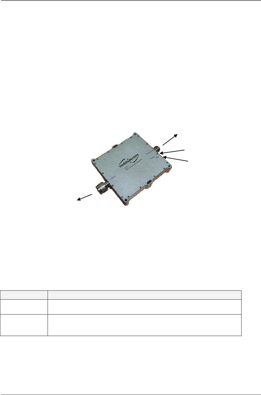
2.2.2 WCE Interfaces, Mounting Support, and LEDs
The WCE unit is equipped with two interface ports: One N-Type male and One N-Type Female for connectivity to
the 860M/R and antenna respectively as shown in Figure 2–3: WCE
Figure 2–3: WCE
The 860M/R interface port, labeled “RHU” is directly connected to the ½” low loss coaxial cable (running to a
remote IDF or telecom closet where it is connected to the 860M/R antenna port via a jumper cable). The “To
Antenna” port is connected to a low-loss jumper (flexible 1’ coax cable) that is directly connected to one of the
many MobileAccess™ supported broadband antennas.
2.2.2.1 WCE Interfaces
The following table describes the interface ports:
Interfaces Description
N-Type Male Used to connect the WCE directly to the coax run from the IDF or Telecom closet
as indicated by the “To RHU” label.
N-Type Female Used to connect any MobileAccess™ supported broadband connection with a
flexible N-Type – N-type Male Jumper cable (typical 1’ length) as indicated by the
“To Antenna” label.
Table 6: WCE Interfaces
”Pwr” LED
”Status” LED
”To RHU”

MA-860 WLAN Solution Components
MA860 Installation and Configuration Guide 9
2.2.2.2 WCE Mounting Support
The following table describes the mounting support:
Mounting Support Description
Mounting Slots Two mounting slots used to affix the unit to any available
building infrastructure via a wire-tie or tie-strap.
Mounting Holes Four mounting holes that support any standard drywall
screw (3/16” in diameter).
Table 7: WCE Mounting Support
2.2.2.3 WCE Status Indicators
The following table describes the purpose of the LED indicators:
LEDs Description
PWR Constant Green: Power supplied to the unit
Status Constant Green: Unit is booting up.
Flickering Green: Unit has completed boot up process and is
operational.
Table 8: WCE LED Indicators

Installation Guidelines
MA860 Installation and Configuration Guide 10
3 I
In
ns
st
ta
al
ll
la
at
ti
io
on
n
G
Gu
ui
id
de
el
li
in
ne
es
s
This section contains general information on the cabling, power, component and installation requirements for the
MA-860 WLAN Solution.
For specific guidelines on infrastructure planning, design and installation, please consult with a MobileAccess™
Project Manager or MobileAccess™ approved Installer.
3.1 MA-860 WLAN Installation Procedure
Once the infrastructure planning and design is completed, the basic steps of installing an MA-860 WLAN Solution
are as follows. As always, for more detailed, specific guidelines, please consult with a MobileAccess™ Project
Manager or MobileAccess™ approved Installer.
1. Install the coax cable runs per design. Refer to Section 3.2 for more details.
2. Properly mount and connect the WCE to the coax cable. A WCE must be installed at each antenna run
that traces back to an Access Point. Refer to Section 3.3.
3. Mount the 860M/R. Refer to Section 3.4.
4. It is recommended to terminate all unused ports on the 860M/R with appropriate 50-ohm loads as
described in Sections 2.1.2 and 2.1.3.
5. Provide power to the MA-860 WLAN Solution. Refer to Section 3.6.4.
6. Confirm that the 860M/R Front Panel Indicator “PWR” LED is Constant Green. Refer to Section 0 for
more details regarding the status of the “PWR” LED indicator.
7. Allow approximately 1-2 minutes for Auto-Discovery to complete and the 860M/R Front Panel Indicator
“Status” LED to be Blinking Green. Refer to Section 0 for more details regarding the status of the
“Status” LED indicator. .
8. Configure the 860M/R network parameters via telnet in order to monitor alarms on the MA-860 WLAN
Solution. For configuration details, refer to Section 0
9. Connect the 860M/R to the customer LAN.
10. Connect Access Points to the 860M/R. Refer to Section 3.8.
11. It is recommended to recycle power to the unit by removing and reinserting the power connector on
the front panel after connecting the APs. If this is done, repeat steps 6 and 7 above and continue.
12. Confirm that the 860M/R Rear Panel Indicator Access Point LEDs are Static Green. Refer to Section
2.1.3.2 for more details regarding the status of the “AP” LED indicator.
13. Access the 860M/R User Interface to confirm all connections are active. Refer to Section 4 .
14. Allow a few minutes for the MA-860 WLAN Solution to complete the cable compensation process in
order to set the appropriate gain on the WCE such that the output power at the WCE is within +/-1dB
of the AP input power to the 860M/R.
15. Access the 860M/R GUI interface Alarm Tab via HTTP and verify that the AP 802.11a/b/g alarms are all
GREEN.

Installation Guidelines
MA860 Installation and Configuration Guide 11
3.2 Coax Cable Connectivity Guidelines
Below are general connectivity guidelines to be followed for the coax cable that connects the 860M/R to the WCE
and the WCE to the multi service Antenna.
For the most recent installation requirements and instructions, please refer current version of the MobileAccess™
Cable Installation FAQ.
For more specific guidelines on infrastructure planning, design and installation, please consult with a
MobileAccess™ Project Manager or MobileAccess™ approved Installer.
• The MA-860 WLAN Solution can utilize the HL4RP-50A coax cable or equivalent.
• The maximum cable length between the 860M/R and WCE for WLAN shall not exceed 300ft. This assumes
that the cable between the WCE and 860M/R has a 6dB/100ft attenuation for 802.11a and a 4dB/100ft
attenuation for 802.11b/g. It is recommended that the user consult with MobileAccess™ Project Manager or
MobileAccess™ approved Installer in order to ensure that the link budget allows for this length.
• The 860M/R Antenna Ports as described in Section 2.1.2- Front Panel Interfaces and Indicator LEDs
connect to the ½” HL4RP-50A or equivalent coax via a 50-ohm, N-female to N-female jumper cable (e.g.
RG142 or equivalent).
• The WCE “To RHU” connection as described in Section 2.2.2 - WCE Interfaces, Mounting Support,
and LEDs connects to the ½” HL4RP-50A or equivalent coax via a 50-ohm, N-male to N-male connection.
• The WCE “To Antenna” connection as described in Section 2.2.2 - WCE Interfaces, Mounting Support,
and LEDs connects to the multi service Antenna via a 50-ohm, N-female to N-male to jumper cable (e.g.
RG142 or equivalent).
Installation Guidelines
MA860 Installation and Configuration Guide 12
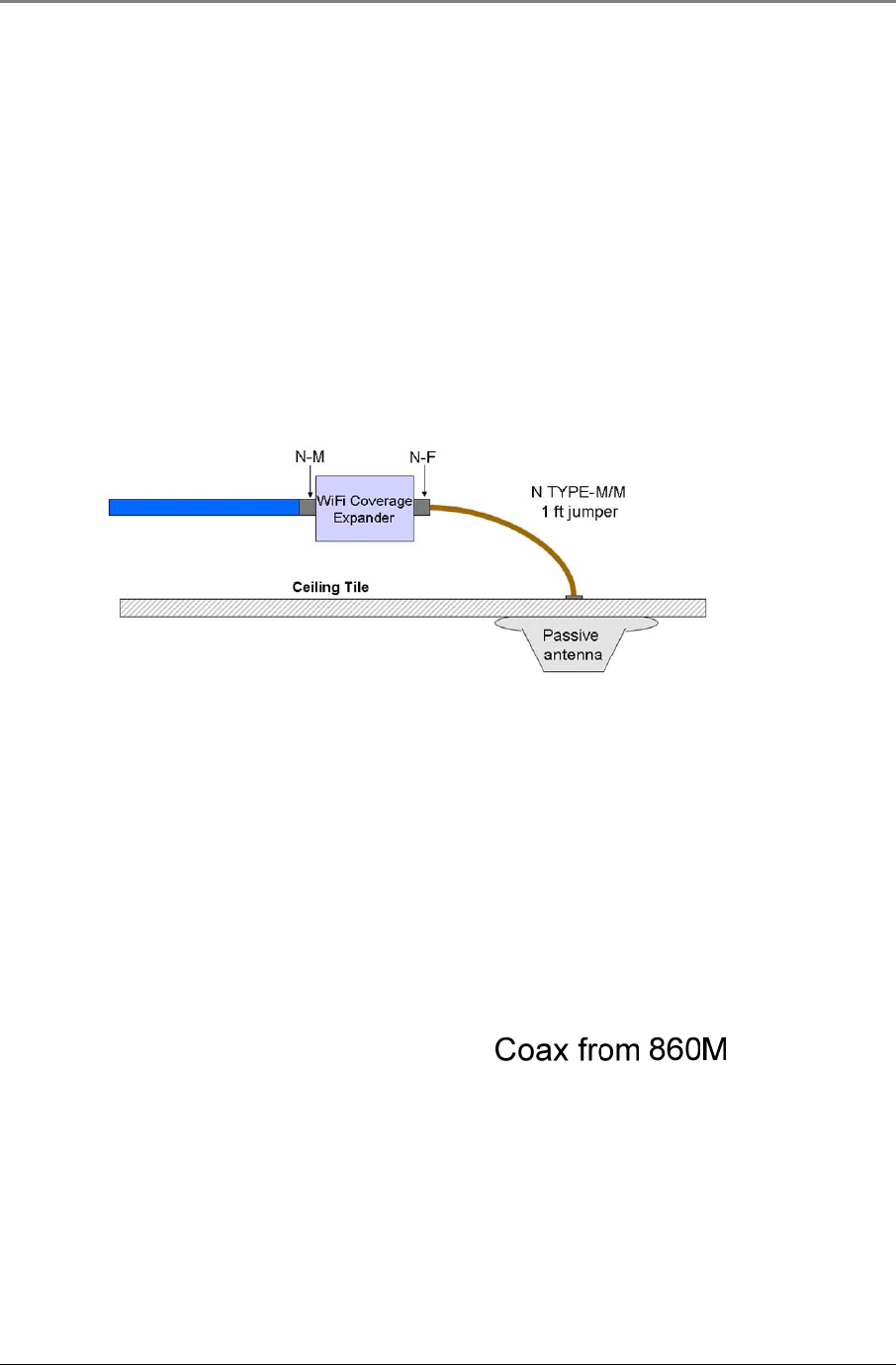
3.3 Wi-Fi Coverage Expander (WCE)
3.3.1 WCE Connection to 860M/R
A WCE must be installed at each antenna run that traces back to an Access Point.
The WCE will be connected on one side (labeled “To RHU”) to a HL4RP-50A or equivalent low loss coaxial cable
(typically running to a remote wiring closet), and to the Passive Broadband Antenna usually through a jumper
(flexible 1' coax cable). Refer to Figure 3–1: WCE Connectivity Block Diagram below:
Figure 3–1: WCE Connectivity Block Diagram
3.3.2 WCE Mounting
There are multiple methods available to mount the WCE in the ceiling depending on user requirements, general
cable installation procedures in accordance with the building codes in the area and as required by the cable
manufacturer. For more specific guidelines, please consult with a MobileAccess™ Project Manager or
MobileAccess™ approved Installer.
The three basic methods for mounting are as follows and are described in the succeeding sections:
3.3.2.1 In Line with Coax Cables
WCE’s light design enables connecting it between the two coax cables (cable from 860M/R and cable from
antenna) without additional support as long as the bend radius of the coax cable is not exceeded.
Installation Guidelines
MA860 Installation and Configuration Guide 13
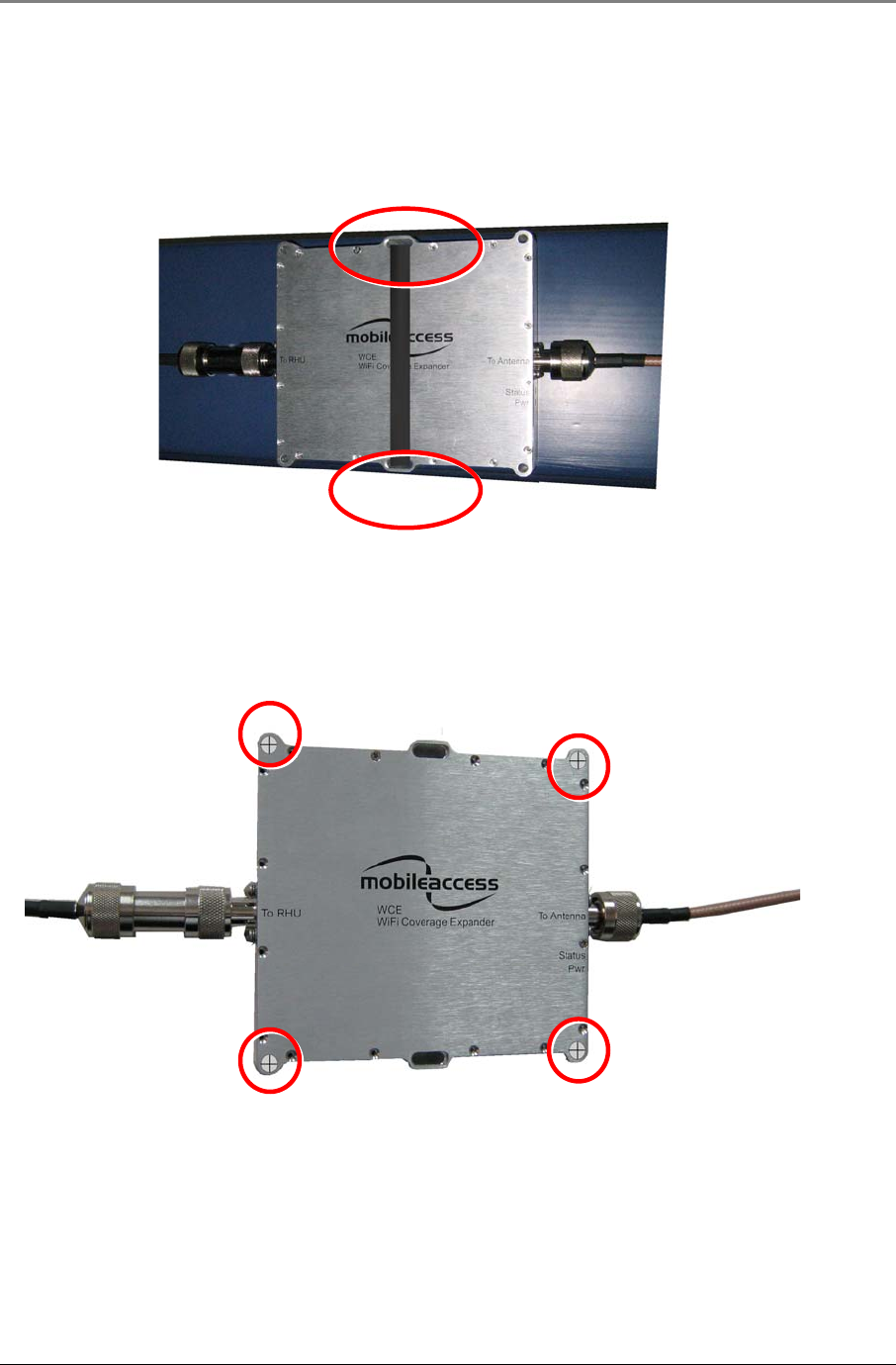
3.3.2.2 Tie Wrap/Wire Tie to a Fixture
Use the two mounting slots used to affix the unit to any available building infrastructure via a wire-tie or tie-
strap (not provided).
Figure 3–2: WCE Mounting with Tie Fixture
3.3.2.3 WCE Wall Mounted Using Four Screws
Secure the WCE using four standard drywall screws (3/16” in diameter).
Figure 3–3: WCE Mounting Using Four Screws

Installation Guidelines
MA860 Installation and Configuration Guide 14
3.4 Installation and Mounting Installation and Mounting
860M/R
MobileAccess™ MA-860 is typically installed in the IDF or Telecom Closet of each floor to which WLAN
coverage is to be supported. The accessories, mounting and installation procedures vary depending on the
deployment option.
There are three typical deployment options as described in section 1.3.
Deployment Options:
1. MA-860 WLAN Solution for WLAN Coverage Only: 860M/R, WCE and Multi-service antennas
2. MA-860 WLAN Solution with MA-1000 for WLAN and Mobile Service Coverage: 860M/R, WCE, Multi-service
antennas, MA-1000 Remote Hub Units (RHUs)
3. MA-860 WLAN Solution with MA-2000 for WLAN and Mobile Service Coverage: 860M/R, WCE, Multi-service
antennas and MA-2000 Remote Unit
In each of the above three deployment options, the 860M/R is typically mounted as follows:
1. Rack mounted: The 860M/R can be placed on a 19” rack using the Rack mountable shelf/bracket
2. Wall mounted: The 860M/R can be mounted directly on the wall
3. Stacked: The 860M/R can be stacked on top of other 860M/R units, on top of the 2000 cabinet or on
top of other RHUs (e.g. MA-1000, MA-1200)
The following sections describe how to mount the 860M/R in the above three scenarios as well as some general
guidelines that should be taken into consideration when installing the 860M/R.
3.4.1 General 860M/R Installation Guidelines
Regardless of which deployment and mounting option is utilized, the following must be taken into consideration
when installing/mounting an 860M/R:
Interfacing to Antenna
• Position of the 860M/R in reference to the coax cable that connects to the antenna must be taken into
consideration. For details see Section 3.2.
• It is recommended to use a jumper cable with appropriate terminators to connect the 860M/R antenna
port to the HL4RP-50A coax cable or equivalent
• The maximum cable length between the 860M/R and WCE for WLAN shall not exceed 300ft (12dB loss
for 802.11b/g and 18dB loss for 802.11a). It is recommended that the user consult with
MobileAccess™ Project Manager or MobileAccess™ approved Installer in order to ensure that the link
budget allows for this length.
Interface to Access Point
• Access Points must be properly placed and installed as defined in Section 3.8.
• The supplied SMA wrench is to be used to tighten the SMA connectors and assist in not over tightening
the connectors.
• The jumper cables used to connect to the Access Points shall be connected with sufficient slack in order
to reduce the strain on the SMA connectors on the 860M/R.
• It is recommended to record the location of the 860M/R units and IP address according to the MAC
addresses on the sticker at the rear of the units near the Ethernet port.
• It is recommended to record the Antenna that corresponds to the Antenna Port of the 860M/R
• It is recommended to record the Access Point that corresponds to the AP Port of the 860M/R

Installation Guidelines
MA860 Installation and Configuration Guide 15
Interface to RHU (MA-1000/MA-1200) and RC (MA-2000)
• Installation and configuration guidelines for the RHU and RC should be taken into consideration as outlined
in their respective User Manuals.
• Jumper cables (N-Type male right angle to SMA male right angle) are to be used to connect the 860M/R to
the MA-1000 or MA-2000 units. Be sure the connectors are closed at a 45 degree angle so as not to place
stress on the cables.
• Jumper cables must be ordered separately and are not supplied with the kits outlined in Section 3.4.2
Mounting and Accessory Kits. It is recommended to use jumper lengths of 6in, 1ft or 5.5ft based on the
relative position of the 860M/R to the RHU and RC.
3.4.2 Mounting and Accessory Kits
The following Mounting accessories can also be ordered when deploying an MA-860 WLAN Solution with Mobile
Services (jumper cables not included).
Part Number Description
BRKT-RHU-800-STK
Stacking bracket for mounting RHU, 860M/R or 1200 on
top of an RHU or 860M/R with screws.
BRKT-1RU-SHELF-2K
Rack mountable shelf for RHU, 860M/R or 1200 with
screws. Can also be used as a stacking bracket for
mounting RHU, 860M/R or 1200 on a 2000 cabinet.
BRKT-1200-STK
Stacking bracket for mounting RHU, 860M/R or 1200 on
top of a 1200 module with screws.
AK-860-SA Stand alone kit with screws for mounting the 860M/R.
Table 9: 860M/R Mounting and Accessory Kits
Installation Guidelines
MA860 Installation and Configuration Guide 16
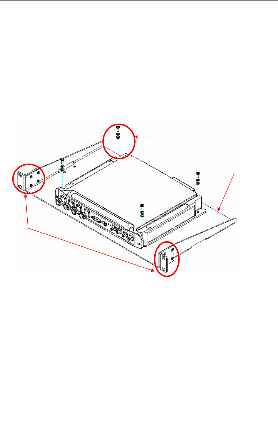
3.4.3 Rack mounted
The 860M/R can be placed on a 19” rack using the Rack mountable shelf/bracket (P/N BRKT-1RU-SHELF-2K)
described in Table 9: 860M/R Mounting and Accessory Kits as follows:
1. Assemble the side brackets using the 4 provided screws as shown in Figure 3–4: 860M/R Rack Mount
Installation.
2. Assemble the 860M/R module to the supplied shelf using the four screws and washers.
3. Mount the shelf assembly in the rack using the side brackets. Take into consideration the position of the
APs and required cable connections.
Figure 3–4: 860M/R Rack Mount Installation
Rack mount shelf
860M/R shelf
mounting screws
Side bracket
assembly
Installation Guidelines
MA860 Installation and Configuration Guide 17
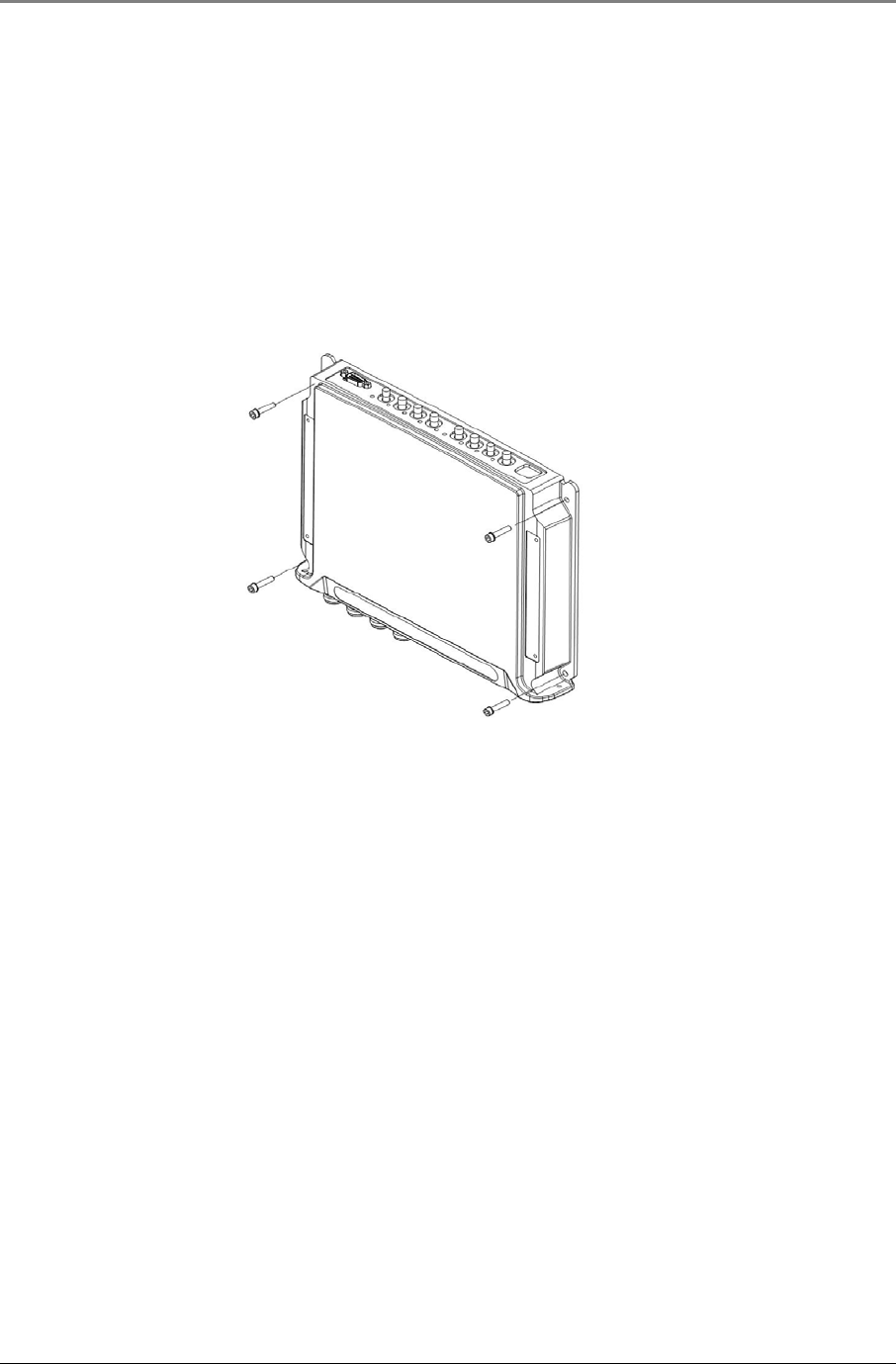
3.4.4 Wall mounted
To mount the 860M/R on the wall follow the below instructions:
1. Mount the 860M/R on the wall using four screws. When mounting, consider the following:
• The type of screws used to mount the unit must suit the type of wall construction (cement, bricks, etc.)
so that the mount is secure.
• The position of the APs and required cable connections.
Figure 3–5: 860M/R Wall Mount Installation
4. Fit 50 ohm terminators on all unconnected SMA, AP and antenna ports.
5. Connect the RJ45 network connection to the MA-860 rear panel network port.
Note: It is recommended to record the location of the units and IP according to the MAC addresses on the
sticker at the rear of the units near the Ethernet port.
Installation Guidelines
MA860 Installation and Configuration Guide 18
3.4.5 Stacked
3.4.5.1 860M/R and MA-1000 RHU
The 860M/R can be mounted such that it is stacked on top of or underneath another 860M/R or RHU. When
stacking modules in this manner, consider the following recommendations:
• When the 860M/R is mounted to the wall, stack the MA-1000 RHU on top in order to allow the
antenna coax cables to properly connect to the 860M/R without hindering access to the MA-1000 RHU
ports.
• When stacking on top of a module connected to the wall, it is recommended to not stack more than 3
modules on top of the module mounted to the wall in order to prevent the screws from breaking or
snapping.
• Take into consideration the distance between the connection points between the 860M/R and MA-
1000 RHU to ensure that the correct SMA to N-Type jumper cables are ordered.
In order to stack the 860M/R on top of or underneath an MA-1000 RHU, follow the steps outlined below:
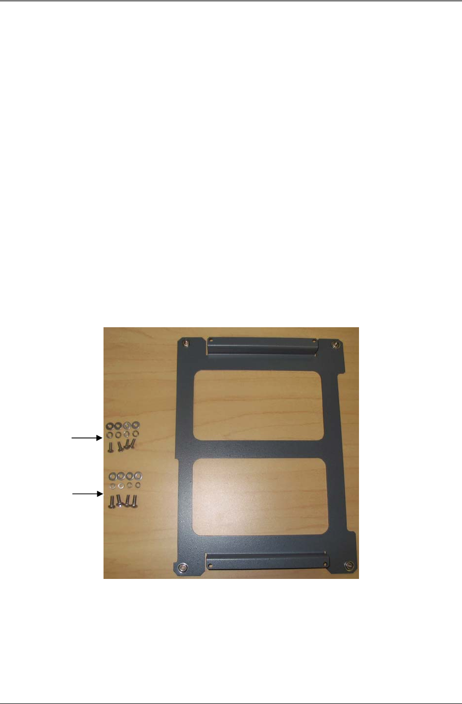
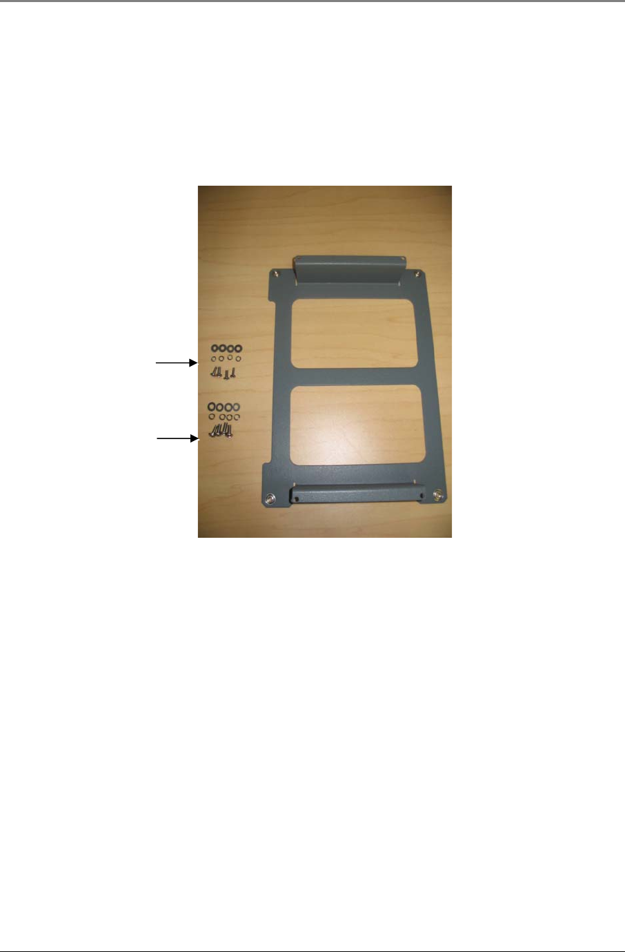
1. The BRKT-RHU-800-STK mounting accessory as described in Section 3.4.2 - Mounting and Accessory
Kits is to be ordered. The kit contents are shown in Figure 3–6: BRKT-RHU-800-STK Contents
Figure 3–6: BRKT-RHU-800-STK Contents
Support bracket
for 860M/R or RHU
Set of 4 8/32” X
7/16” Screws with
#8 Lock and Flat
Washers
Set of 4 6/32” X
3/8” Screws with
#6 Lock and Flat
Washers
Installation Guidelines
MA860 Installation and Configuration Guide 19
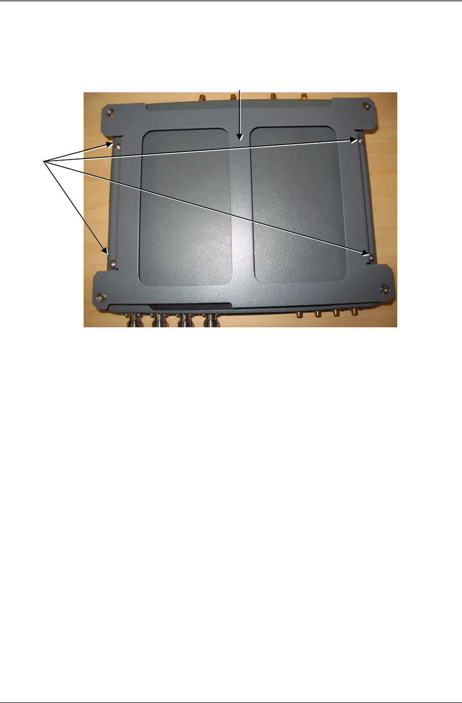
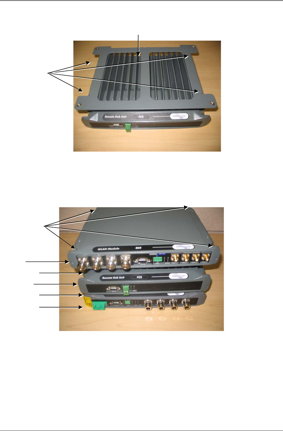
2. Place the support bracket BRKT-RHU-800-STK on top of the 860M/R where the notched side of the
bracket is towards the rear of the unit and secure in place with supplied screws as shown in Figure 3–7:
BRKT-RHU-800-STK Placement on 860M/R
Figure 3–7: BRKT-RHU-800-STK Placement on 860M/R
3. Mount the 860M/R and bracket assembly to the wall. When mounting, consider the following:
• The type of screws used to mount the unit must suit the type of wall construction (cement, bricks, etc.)
so that the mount is secure.
• The position of the APs and required cable connections.
Set of 4 6/32” X
3/8” Screws with
#6 Lock and Flat
Washers
Support bracket placement on 860M/R
Installation Guidelines
MA860 Installation and Configuration Guide 20
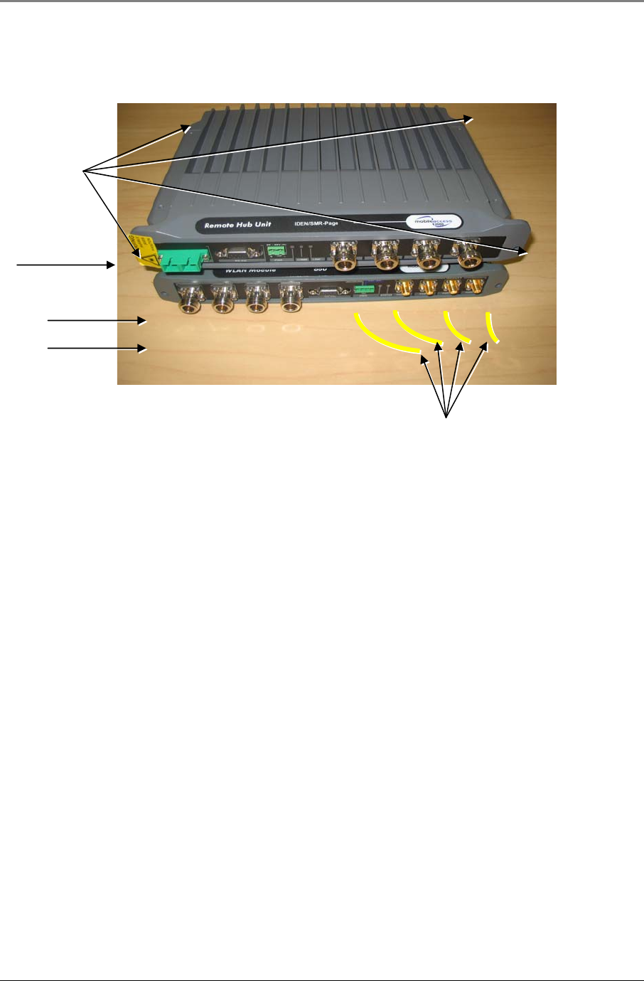
4. Stack the MA 1000 RHU to the bracket using the four provided screws and connect the RHU to the 860M/R
with SMA to N-Type jumper cables (not provided) as shown in Figure 3–8: RHU stacked on top of
860M/R. It is recommended to use jumper lengths of 6in, 1ft or 5.5ft based on the relative position of the
860M/R to the RHU.
Figure 3–8: RHU stacked on top of 860M/R
SMA to N-Type
j
umpers (to be ordered
separately)
RHU
860M/R
Support Bracket
Set of 4 8/32” X
7/16” Screws with
#8 Lock and Flat
Washers
Installation Guidelines
MA860 Installation and Configuration Guide 21
3.4.5.2 860M/R and MA-1200 RHU
If an 860M/R is to be stacked underneath an MA-1200, follow instruction in Section 3.4.5.1 860M/R and MA-
1000 RHU.
However, in typical installations the following two scenarios are seen:
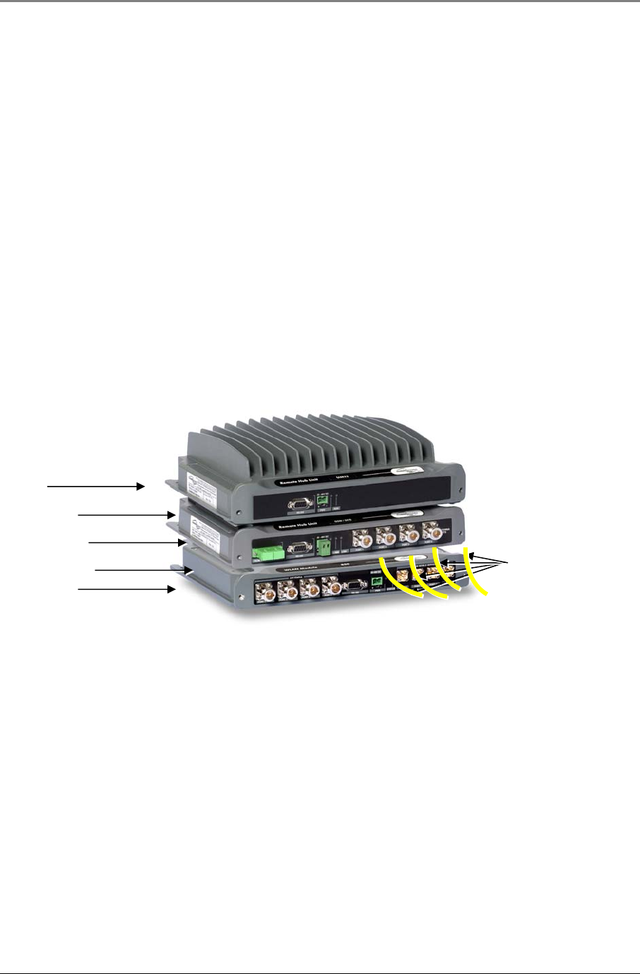
A. The MA-1000 is sandwiched between the 860M/R and MA-1200, where the MA-1200 is above the MA-1000
RHU and the 860M/R is below the MA-1000 RHU.
B. The MA-1200 module is sandwiched in between the 860M/R and MA-1000 RHU, where the 860M/R is above
and the MA-1000 RHU is below the MA-1200.
Refer to the MA-1000 or MA-1200 installation manual for instructions in the case of Scenario A. The completed
assembly should resemble Figure 3–9: 860M/R, MA-1200 and MA-1000 Assembly (Scenario A). SMA to
N-Type jumper cables jumper cables from the MA-1000 to the 860M/R are not included and are to be ordered
separately. It is recommended to use jumper lengths of 6in, 1ft or 5.5ft based on the relative position of the
860M/R to the RHU.
Figure 3–9: 860M/R, MA-1200 and MA-1000 Assembly (Scenario A)
MA-1200
860M/R
Support Bracket
Support Bracket
MA-1000 SMA to N-Type
j
umpers (to be ordered
separately)
Installation Guidelines
MA860 Installation and Configuration Guide 22
Follow the instructions outlined below in the case of Scenario B:
1. Follow instructions outlined in Section 3.4.5.1- 860M/R and MA-1000 RHU to stack an MA-1200 on top
of an MA-1000 RHU.
2. Use the BRKT-1200-STK mounting accessory as described in Section 3.4.2 - Mounting and Accessory
Kits to mount the 860M/R on top of the MA-1200. The kit contents are shown in Figure 3–10: BRKT-
1200-STK Contents.
Figure 3–10: BRKT-1200-STK Contents
3. Place the support bracket BRKT-1200-STK on top of the MA-1200 where the notched side of the bracket is
towards the rear of the unit and secure in place with supplied screws as shown in Figure 3–11: BRKT-
1200-STK on top of MA-1200.
Stacking bracket
for MA-1200
Set of 4 8/32” X
7/16” Screws with
#8 Lock and Flat
Washers
Set of 4 6/32” X
3/8” Screws with
#6 Lock and Flat
Washers
Installation Guidelines
MA860 Installation and Configuration Guide 23
Figure 3–11: BRKT-1200-STK on top of MA-1200
4. Stack the 860M/R to the bracket using the four provided screws and connect the MA-1000 RHU to the
860M/R with SMA to N-Type jumper cables (not provided) as shown in Figure 3–12: 860M/R, MA-1200
and MA-1000 Assembly. It is recommended to use jumper lengths of 6in, 1ft or 5.5ft based on the relative
position of the 860M/R to the RHU.
Figure 3–12: 860M/R, MA-1200 and MA-1000 Assembly (Scenario B)
3.4.5.3 860M/R and MA-2000 RC
The 860M/R can be mounted with the MA-2000 Remote Cabinet in the following configurations:
1. Rack mounted (see Section 0 ) above the MA-2000
2. Wall mounted (see Section 0 ) near the MA-2000
3. Directly on top of the MA-2000 cabinet as defined in this section.
Bracket placement on MA-1200
Set of 4 6/32” X
3/8” Screws with
#6 Lock and Flat
Washers
Set of 4 8/32” X
7/16” Screws with
#8 Lock and Flat
Washers
MA-1200
MA-1000
Support Bracket
860M/R
Stacking Bracket
Installation Guidelines
MA860 Installation and Configuration Guide 24
In each of the above three configurations, consider the following take into consideration the distance between
the connection points between the 860M/R and MA-2000 RC to ensure that the correct SMA to N-Type jumper
cables are ordered.
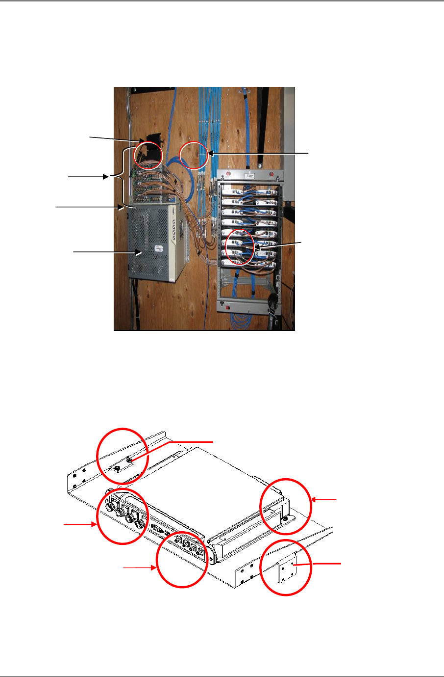
In order to stack the 860M/R on top of the MA-2000 as shown in Figure 3–13: 860M/R Stacked on top of
MA-2000, follow the steps outlined below:
Figure 3–13: 860M/R Stacked on top of MA-2000
4. Assemble the BRKT-1RU-SHELF-2K by screwing on the side brackets as illustrated in Figure 3–14.
860M/R MA-2000 Stacking Bracket Assembly with the four screws and washers.
5. Screw in the 860M/R module to the supplied shelf using the four screws and washers as illustrated in
Figure 3–14. 860M/R MA-2000 Stacking Bracket Assembly. Make sure to orient the 860M/R as
illustrated.
Figure 3–14. 860M/R MA-2000 Stacking Bracket Assembly
860M/R Mobile Services Ports
860M/R Antenna Ports
MA-2000 Antenna Ports
Four 860M/R
Stacking Bracket
MA-2000
860M/R Mobile
Services Ports
860M/R Antenna
Ports
860M/R shelf
mounting screws
Side bracket
assembly
Side bracket
assembly
Installation Guidelines
MA860 Installation and Configuration Guide 25
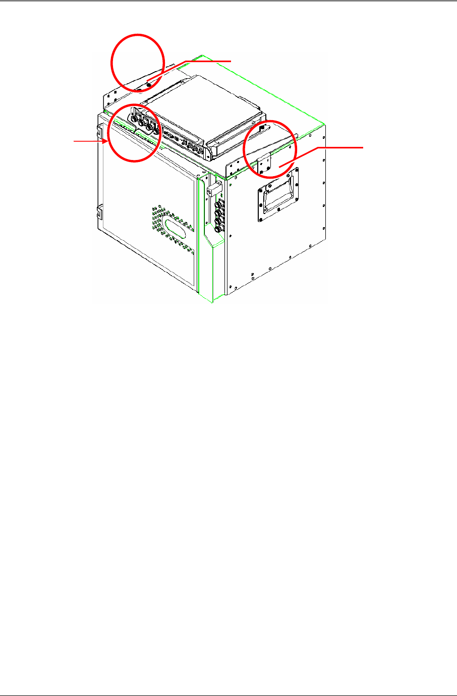
6. Assemble the shelf to the MA-2000 RC by securing the side brackets to the cabinet sides as illustrated below
in Figure 3–15. Illustration of 860M/R Mounted on MA-2000 RC.
Figure 3–15. Illustration of 860M/R Mounted on MA-2000 RC
7. Connect the MA-2000 RC antenna ports to the 860M/R front panel Mobile Service port connectors as
illustrated in Figure 3–17. Illustration of MA-2000 Antenna Port Connections to 860M/R.
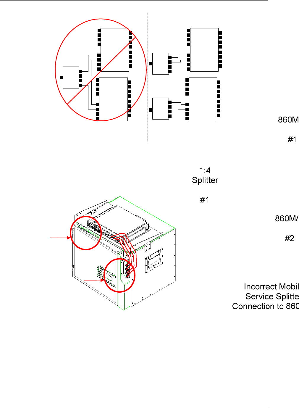
8. In the case where each of the MA-2000 Antenna ports is connected to splitters (e.g. 1:4 splitter), the output
of the splitters is to be connected to the appropriate 860M/R Antenna interface such that:
a. The 1:4 splitter should be connected such that all four outputs of the splitter are connected to the
same 860M/R unit. Multiple 860M/R units cannot connect to the same splitter. Refer to the
illustration in Figure 3–16: Mobile Service Splitter Connection to 860M/R for an example.
b. The splitters should be placed or mounted such that they are not physically touching each other to
eliminate crosstalk between the splitters. So for example, if installation constraints require the
splitters to be stacked on top of each other, it is recommended to place a small piece of cardboard
between the units.
860M/R Antenna
Ports
Side bracket
assembly
Side bracket
assembly
Installation Guidelines
MA860 Installation and Configuration Guide 26
Figure 3–16: Mobile Service Splitter Connection to 860M/R
9. Connect the 860M/R antenna ports to the coax cable that interfaces with the appropriate broadband
antenna.
Figure 3–17. Illustration of MA-2000 Antenna Port Connections to 860M/R
MA-2000 Antenna
Ports
860M/R Antenna
Ports

Installation Guidelines
MA860 Installation and Configuration Guide 27
3.5 Configuring Network Parameters
Before deploying the device on the customer LAN, network configurations for each 860M/R module are
configured as defined in this section.
Once the 860M/R is configured correctly, it can be connected to the customer LAN in order to provide alarm
information via SNMP traps or via a web interface.
Network parameters are to be configured via Telnet.
3.5.1 Default Settings
The 860M/R is shipped from the factory with the following default settings:
IP address: 192.168.1.1
Subnet mask: 255.255.0.0
Default GW: 192.168.254.254
3.5.2 Changing the Network Settings
This section lists the procedure to follow in order to change the network settings on each 860M/R unit. It is
assumed that the user has basic knowledge to configure the network settings on a laptop and access a
command prompt.
The example screen shots in Figure 3–18, Figure 3–19 and Figure 3–20 demonstrate the steps outlined in
this section in order to configure the 860M/R Network Settings as follows:
a. IP address: 192.168.1.10
b. Subnet mask: 255.255.255.0
c. Default gateway: 192.168.1.254
1. Note the current network settings (IP address and Subnet mask) of the 860M/R unit that is to be
configured. In order to recover the current settings, follow the directions in Section 5.3 - 860M/R
Network Configuration Recovery Procedure.
2. Configure the laptop Local Area Connection TCP/IP settings such that the IP address of the laptop is on the
same subnet as the 860M/R. For example, if changing the default parameters on the 860M/R, the laptop
TCP/IP settings can be configured as follows:
a. IP address: 192.168.1.2
b. Subnet mask: 255.255.0.0
c. Default gateway: This can be left blank
3. Connect the laptop Ethernet Port to the 860M/R Ethernet Port (see Section 2.1.3) via a Cat 5/5e/6 cross
cable.
4. Open a command prompt and confirm that the laptop is able to communicate to the 860M/R by pinging the
860M/R IP address “A.B.C.D” via the following command (If there is no reply, confirm that the laptop is on
the correct subnet as the 860M/R and that a cross over cable is being utilized):
>
ping A.B.C.D
(A.B.C.D is the IP address of the 860M/R. If the 860M/R still has default configuration, this should be
192.168.1.1).
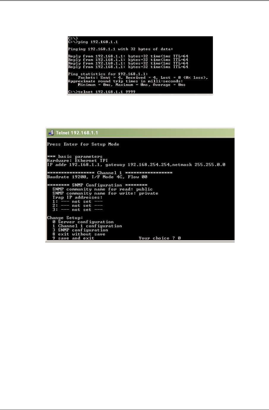
5. Open a Telnet connection to port 9999, and press Enter to go into Setup Mode within 5 seconds otherwise,
connection to the host is lost. If this occurs, open up another command prompt and repeat this step.
Installation Guidelines
MA860 Installation and Configuration Guide 28
>
telnet 192.168.1.1 9999
6. A summary of current configurations on the 860M/R will be displayed along with a menu of setup options.
In order to change the network parameters, enter “0” to select Server Configuration when prompted.
Figure 3–18: Configuring 860M/R Network Settings Steps 5-6
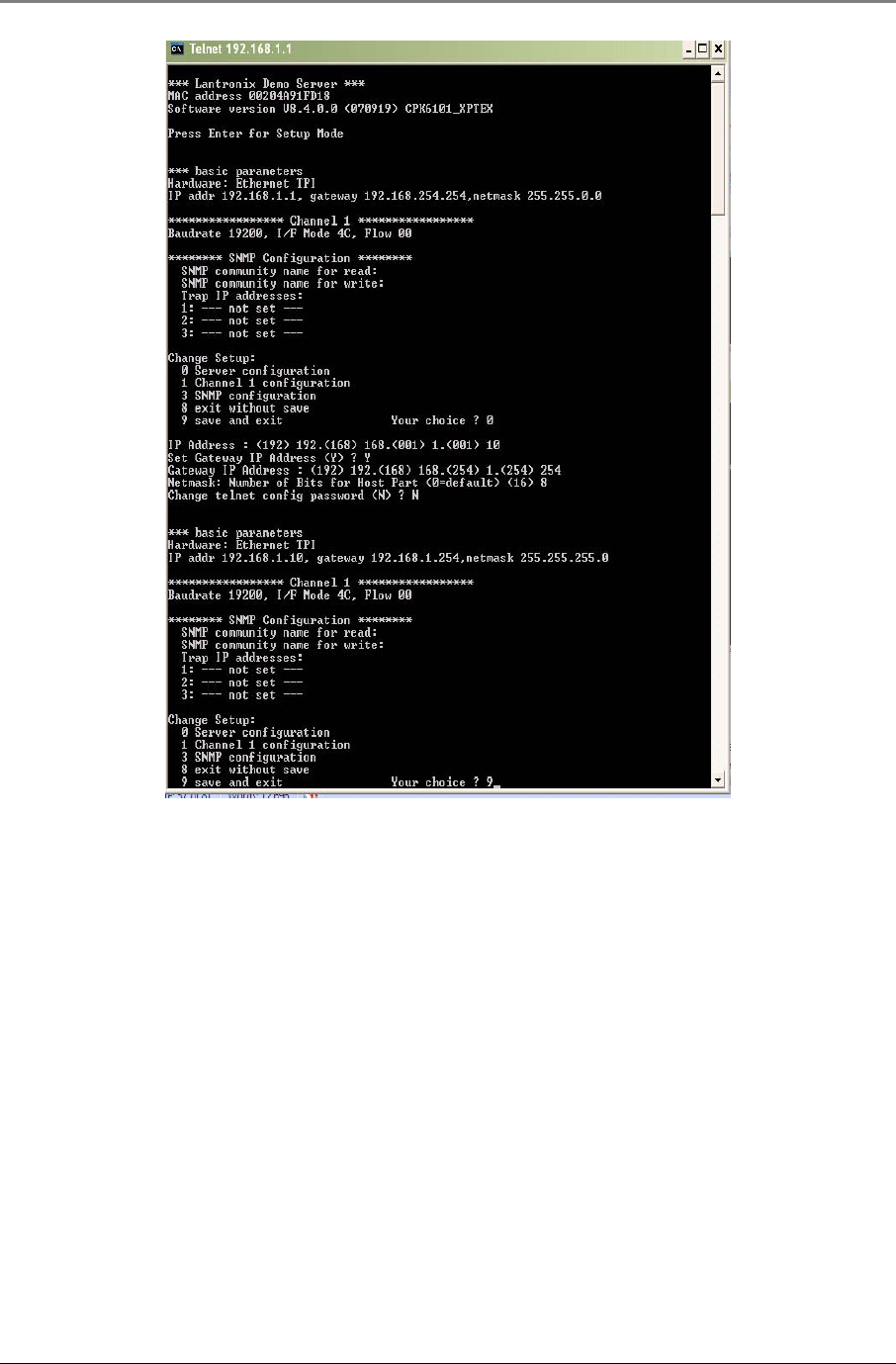
7. Enter a new static IP address. If you wish to configure the 860M/R to DHCP, enter 0.0.0.0
Figure 3–19: Configuring 860M/R Network Settings Step 7
8. Enter “Y” to set the Gateway IP address, else enter “N”.
9. Enter the number of host bits in the netmask. For example, a subnet mask of 255.255.0.0 would have 16
host bits. A subnet mask of 255.255.255.0 would have 8 host bits.
10. The next step is to change the telnet password. By default, there is no telnet password. It is advised to
skip this step. If the telnet password is forgotten, there isn’t a way to change the network configurations of
the 860M/R or reset everything to factory default.
11. Review the changes made and enter “0” to save changes and continue back to the main screen; enter “8” to
leave original settings and exit the telnet session; or enter “9” to save the changes and exit the telnet
session.
Installation Guidelines
MA860 Installation and Configuration Guide 29
Figure 3–20: Configuring 860M/R Network Settings Steps 8-11
3.5.3 Setting SNMP Parameters
The steps in this section assume that the Network Settings have already been configured or that the IP address
of the 860M/R is known. If this is not the case, refer to Section 3.5.2 - Changing the Network Settings to
configure the Network Parameters or Section 5.3- 860M/R Network Configuration Recovery Procedure
to recover the IP address of the 860M/R.
This section assumes that the 860M/R network settings have already been configured based on the steps
outlined in Figure 3–18, Figure 3–19 and Figure 3–20 to the following settings:
a. IP address: 192.168.1.10
b. Subnet mask: 255.255.255.0
c. Default gateway: 192.168.1.254
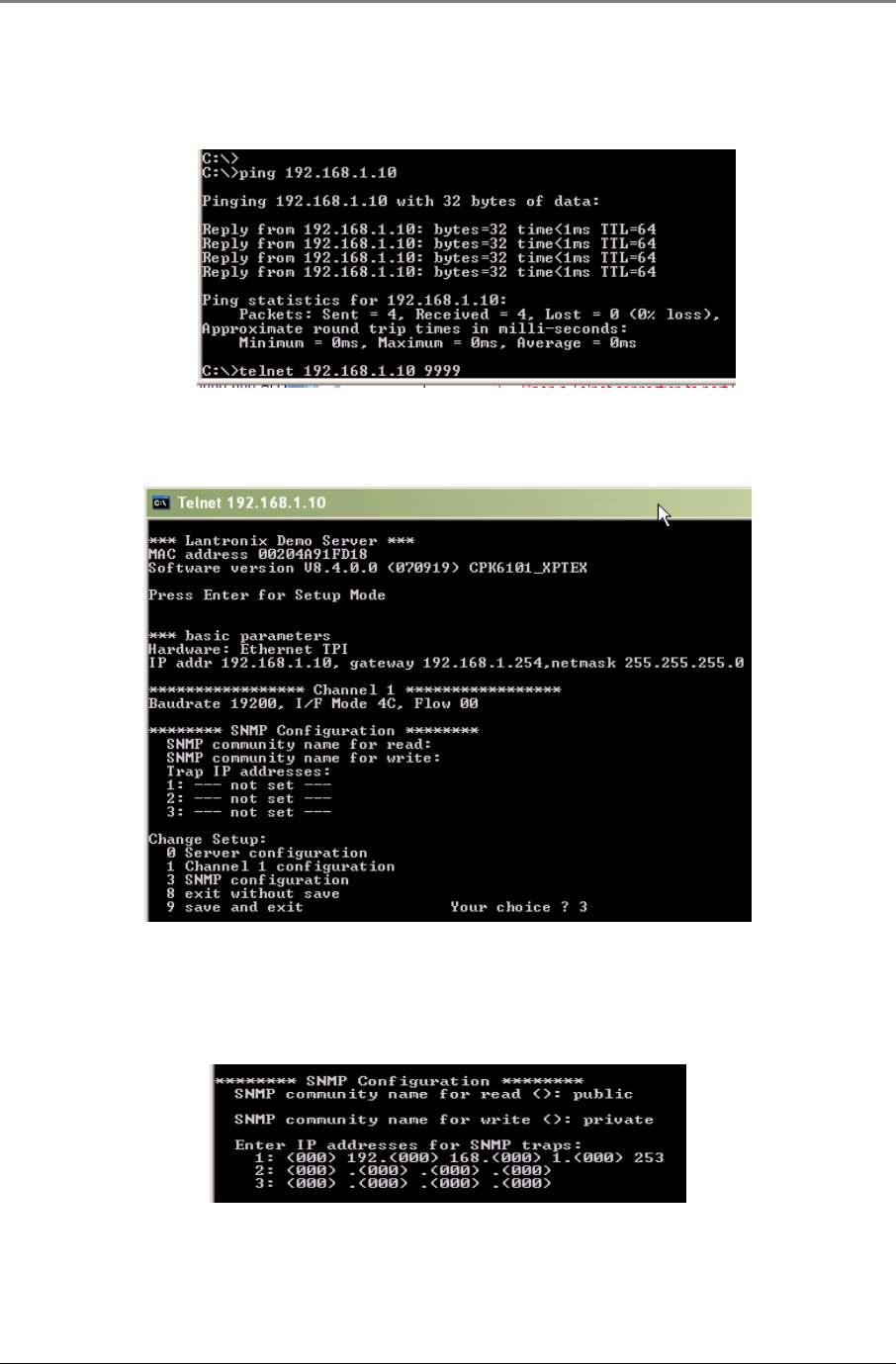
1. Open a command prompt and confirm that the laptop is able to communicate to the 860M/R by pinging the
860M/R IP address. For this example, the 860M/R has an IP address of 192.168.1.10. (If there is no reply,
confirm that the laptop is on the correct subnet as the 860M/R and that a cross over cable is being utilized):
>
ping 192.168.1.10
Installation Guidelines
MA860 Installation and Configuration Guide 30
2. Open a Telnet connection to port 9999, and press Enter to go into Setup Mode within 5 seconds otherwise,
connection to the host is lost. If this occurs, open up another command prompt and repeat this step.
>
telnet 192.168.1.10 9999
Figure 3–21: Setting SNMP Parameters Steps 1-2
3. A summary of current configurations on the 860M/R will be displayed along with a menu of setup options.
In order to change the network parameters, enter “3” to select Server Configuration when prompted.
Figure 3–22: Setting SNMP Parameters Step 3
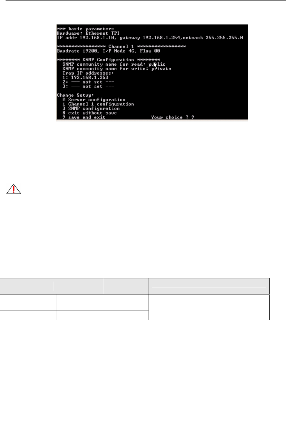
4. Set the SNMP Read and Write community names and the SNMP traps destination addresses (up to three
addresses can be defined). Press return after each entry. In this example, the read community name is set
to “public”, the write community name is set to “private” and only one trap destination address is set to
“192.168.1.253”.
Figure 3–23: Setting SNMP Parameters Step 4
5. The parameters setting summary should appear. Review the changes made and enter “0” to save changes
and continue back to the main screen; enter “8” to leave original settings and exit the telnet session; or
enter “9” to save the changes and exit the telnet session.
Installation Guidelines
MA860 Installation and Configuration Guide 31
Figure 3–24: Setting SNMP Parameters Step 5
3.6 Power Consumption and Power Supplies
3.6.1 Power Safety Instructions
SAFETY WARNINGS
When installing or selecting the power supplies:
1. Be sure to disconnect all power sources before servicing.
2. Calculate the required power according to the requirements of the specific installation and then determine
the configuration of the power supplies. The required DC cables will then be determined by the selected PS
configuration.
3. Use only UL approved power supplies
4. AC and DC power supply cables – use only the power cords supplied with the units
3.6.2 Input Power Requirements
Device Voltage Input Power
Consumption Notes
860M/R + Four
WCEs 20-60 VDC 40W
860R + Four WCEs 20-60 VDC 40W
860M/R has a 5W maximum power draw.
Each WCE has a maximum 8.5W power draw.
Table 10: MA-860 WLAN Solution Power Requirements

Installation Guidelines
MA860 Installation and Configuration Guide 32
3.6.3 MobileAccess™ Supplied Power Supplies
The following power supplies are provided with the 860M/R:
Power Supply Manufacturer Model Number Input Power Output Power
Main Mean Well P66A-8AD01 100-240VAC, 50/60Hz, 1.5A 48V, 66W
Redundant SINPRO SPU65-104-9.8V 100-240VAC, 47-63 Hz, 1.9 A 9.8V, 75W
Table 11: MobileAccess™ Supplied Power Supplies
3.6.4 Connecting Power Supply to the MA-860 WLAN Solution
The 860M/R supplies power to the WCE via the coax. Therefore, the power supplies are connected directly to
the PWR port on the 860M/Rin order for power to be supplied to both the 860M/R module and the WCE.
Each 860M/R module comes with a splitter cable, which has three connection points. One connection point of
the cable connects directly to the 860M/R PWR port; one connects to the Main Power supply; and one connects
to the redundant power supply.
The 860M/R also provides a bracket that allows for the power cable to remain securely attached to the 860M/R.
Follow the steps below and refer to Error! Reference source not found. for a complete assembly.
1. Remove the two center screws (Item A).
2. Connect the power cable to the PWR port of the 860M/R.
3. Assemble the bracket (Item B) and reaffix the two screws (Item A).
4. Assemble the bracket (Item B) and reaffix the two screws (Item A).
Figure 3–25: Connecting Power Supply to the MA-860 WLAN Solution
Item A: Two center
screws on 860M/R
Item B: Power
Cable Support
Bracket

Installation Guidelines
MA860 Installation and Configuration Guide 33
3.7 MobileAccess™ Supported Multi Service Antennas
The table below provides the list of approved antennas for use with the MA-860 WLAN Solution. Please consult
with the manufacture provided data sheet for the most recent technical specification information.
Manufacturer Model Number Description Frequency
Range
(MHz)
Gain
(dBi) Notes
Huber Suhner® SWA 0859/360/4/10/V
Sencity® Art Antenna
for Wireless
Communication
806-960
1710-2170
2400-5875
5
6
7
A
ll supported frequency
ranges have linear vertical
polarization.
MobileAccess™ ANT-600-6G-OMN
MobileAccess™
Omnidirectional Multi-
Service Antenna
(380MHz – 6GHz)
380-512
596-606
608-614
698-960
1395-1432
1710-2170
2400-2485
5150-5850
-3
0
0.5
0.5
1
3
3
4
Supported frequencies from
380MHz – 1432MHz have
circular polarization. All
other frequencies have
vertical polarization.
Mars MA-CQ26-1X 380MHz – 6GHz Multi
Band Omni Antenna
380-460
608-614
1395-1432
806-960
1700-2170
2400-2500
3400-3700
4900-6000
1
1
5
4
6
6
6
6
A
ll supported frequency
ranges have linear vertical
polarization.
Table 12: MobileAccess™ Approved Multi-Service Antennas
3.8 Access Points
This section lists the approved APs to be used with the MobileAccess™ system as well as the procedures
required to prepare the APs for operation and installation.
3.8.1 Approved APs
MobileAccess™ has acquired regulatory approval for the MA-860 WLAN Solution as shown in Table 13: FCC
Approved Access Points. As a result, the user must properly label the APs as follows:
1 Verify that the WLAN APs utilized are on the approved list for the appropriate regulatory body
2 Apply the appropriate label (supplied by MobileAccess™) on the AP, near the existing certification labels,
making sure it does not cover or obstruct the view of other certifications or required information.

Installation Guidelines
MA860 Installation and Configuration Guide 34
FCC
MobileAccess™ has received the FCC–47, CFR 15.109, Part 15 Sections B, C, and E certification. As per this
certification, each MA-860 WLAN System is supplied with FCC certification labels that correspond to the MA-860
and connected APs as per Table 13: FCC Approved Access Points below.
MobileAccess™ FCC ID Access Point Vendor Access Point Model Functionality
OJFMA860WCE-AU Cisco 1242 Dual radio 802.11 a/b/g
Table 13: FCC Approved Access Points
3.8.2 AP Connection and Configuration with MA-860
An MA-860 WLAN module provides support for up to four 802.11a/b/g APs (four ‘a’ ports and four ‘b/g’ ports.
Signals from an AP connected to the MA-860 port labeled “Access Point 1” are routed out the MA-860 port
labeled “ANT 1”; signals from an AP connected to the MA-860 port labeled “Access Point 2” are routed out
the MA-860 port labeled “ANT 2”; and so on. More detailed information can be found in Section 2.1.3 Rear
Panel Interfaces and Indicator LEDs above.
Follow the steps below to properly connect and configure an AP to use with the MA-860 WLAN Solution:
1. Apply the appropriate FCCID label (refer to Table 13: FCC Approved Access Points) supplied with the
860M/R on the Access Point.
2. Using an RP-TNC/RP-SMA (see
Table 14: AP Termination
) to SMA jumper cable, connect the right
primary port of the AP to the MA-860 “Access Point” port. Note that the 5.1GHz AP antenna port should
be connected to the “802.11a Access Point” port and the 2.4GHz AP antenna port should be connected to
the “802.11b/g Access Point” port.
3. Terminate all unused AP and 860M/R ports with an appropriate 50-ohm load (see
Table 14: AP
Termination
). Four SMA Male RF 50-ohm loads are supplied with the 860M/R.
4. Supply power to the AP per AP vendor specifications.
5. If the AP has diversity antennas, refer to AP vendor specification to configure the AP to transmit and receive
only across the right, or primary, external port of all connected APs. Disable the left, or secondary, external
port of all connected APs.
6. Once the customer has configured the AP to the appropriate channel/power configuration per AP vendor
specifications as required/decided upon by the customer, confirm that the Status light for each “Access
Point” port is illuminated GREEN. NOTE: A minimum of -6dBm of power is required to be transmitted by
the AP for the 860M/R to recognize the AP as being active.
Access Point
Vendor
Access Point
Model
Access Point
Termination
Mating Connector for 50-ohm
Load or Jumper Cable
Cisco 1242 RP-TNC Plug (Female) RP-TNC Jack (Male)
Table 14: AP Termination
Installation Guidelines
MA860 Installation and Configuration Guide 35
3.8.3 AP Installation in IDF or Telecom Closet
Confirm that the MobileAccess recommends that each independent IDF Telecom closet is adequately planned for
installation of the access points to increase the amount of isolation and reduce the amount of RF leakage
between access points.
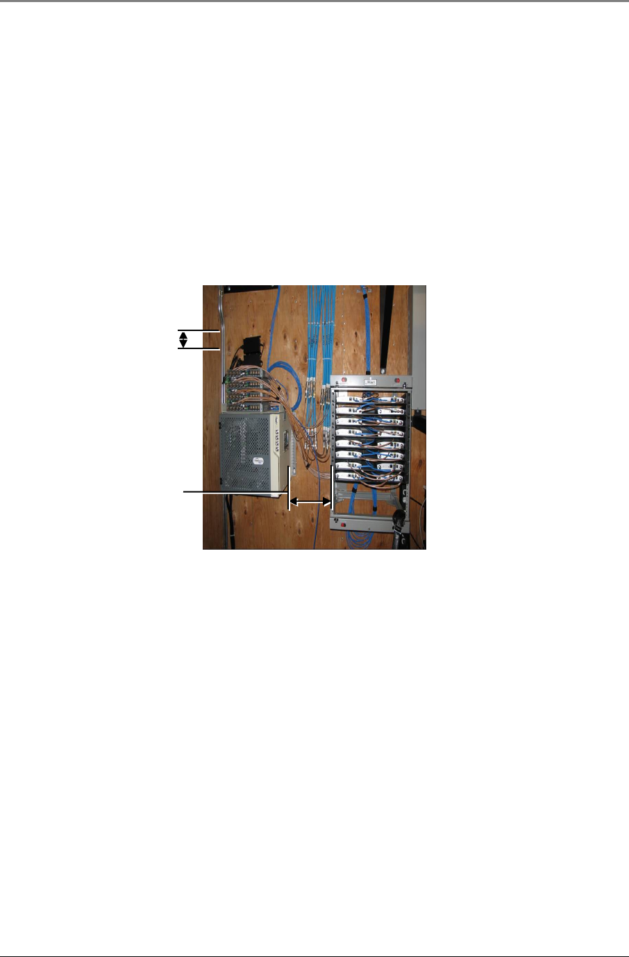
MobileAccess™ has also found that mounting the access points in a 19” rack system has proven to be effective
against RF leakage between access points. The APs must be physically separated as follows to eliminate any
RF contention or leakage from AP to AP:
• Minimum Horizontal AP to AP Separation: 4in (Four inches)
• Minimum Vertical AP to AP Separation: 1U (1 rack unit)
Refer to Figure 3–26: Access Point Mounting below for an example of the separation and mounting
requirements.
Figure 3–26: Access Point Mounting
4in
1U

MA-860 WLAN Solution Graphical User Interface (GUI)
MA860 Installation and Configuration Guide 36
4 M
MA
A-
-8
86
60
0
W
WL
LA
AN
N
S
So
ol
lu
ut
ti
io
on
n
G
Gr
ra
ap
ph
hi
ic
ca
al
l
U
Us
se
er
r
I
In
nt
te
er
rf
fa
ac
ce
e
(
(G
GU
UI
I)
)
The MA-860 WLAN solution provides the user with a Graphical User Interface (GUI) in order to access
configuration and status information of the MA-860.
4.1 Accessing the GUI
The MA-860 GUI can be accessed by following the procedure below:
1. Configure the 860M/R unit with an IP address by following the procedure outlined in Section 0 .
2. Configure the IP address of the 860M/R to be on the same subnet as the 860M/R.
3. If accessing the 860M/R directly, connect the PC to the 860M/R Ethernet Port via a cross over cable. If
accessing the 860M/R via a LAN, connect the PC to the LAN making sure that the PC is on the same
network as the 860M/R.
4. Open a command prompt on the PC and confirm that the laptop is able to communicate to the 860M/R
by pinging the 860M/R IP address “A.B.C.D” via the following command:
>
ping A.B.C.D
(A.B.C.D is the IP address of the 860M/R)
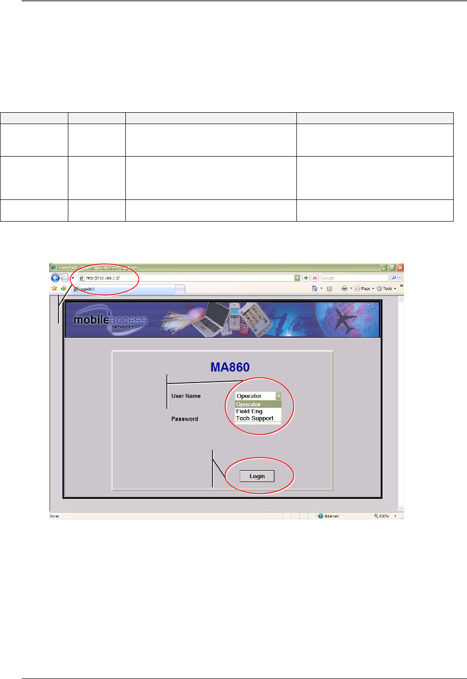
5. Open up a Web Browser application (e.g. Microsoft Internet Explorer)
6. Enter the IP address of the 860M/R into the address bar of the Web Browser (e.g. http://A.B.C.D,
where A.B.C.D is the IP address of the 860M/R).
7. Login to the GUI based on the User Account level (see Section 0 ).
8. Refer to Section 4.3 - 0 for details on the information provided in the GUI.
Note: The Web GUI screen is refreshed automatically; however, if necessary, click the same tab
again (do not use the Web Browser Refresh option).
MA-860 WLAN Solution Graphical User Interface (GUI)
MA860 Installation and Configuration Guide 37
4.2 Login and User Account Levels
The available login credentials and default passwords are defined in Table 15. Please note that the password is
case sensitive.
Username Password Accessibility Information Accessible MA-860 GUI Tabs
Operator oper Monitoring options only.
- General
- Adjustments (View Only)
- Alarm
Field Engineer eng Monitoring and limited configuration
options only.
- General
- Adjustments (View and
Configuration)
- Alarm
TechSupport N/A
Reserved for MobileAccess technical
support only.
Reserved for MobileAccess technical
support only.
Table 15: MA-860 GUI Login and User Account Levels
Figure 4–1 below is a screen capture of the login screen.
Figure 4–1: 860M/R GUI Login Screen
Click Login once
Username and
Password is entered
Select User Name and
enter password as
described in Table 15
IP address of
the 860M/R

MA-860 WLAN Solution Graphical User Interface (GUI)
MA860 Installation and Configuration Guide 38
4.3 MA-860 GUI Control Information
Upon login, the default display is the General tab of the Control Screen. The Control Screen provides the user
with access to the following tabs:
Tab Option Description
General Unit identification and version information, and WCE
information for each channel.
Adjustments Unit cable compensation adjustments.
Alarms Alarm monitoring
4.3.1 General Tab Information
The General Tab on the Control Information screen of the GUI provides users access to the following
information:
Purpose The purpose of the General tab information is to provide the user with
information about the MA-860
Information Provided 1 860M/R Unit Information
a. Hardware and Software Version Number
b. Hardware Serial Number
c. Network Configuration Settings (for 860M/R unit)
d. Product Version Information if applicable
2 Antenna #1-4 Information
a. Provides the following information for the WCE unit connected to a
specific antenna port
i. Hardware Serial Number
ii. Software Version Number
iii. Product Version Information if applicable
b. If there is no WCE connected at the end of the coax run of the
associated Antenna port, the information is blank
c. If a WCE was connected at one point but was then removed, the WCE
information will be grayed out until the 860M/R unit goes through a
power cycle or auto discovery process.
3 The Apply button on this screen is not enabled since there are no user
adjustable parameters on this screen.
User Level Access Operator and Field Eng.
Reference Figure Figure 4–2
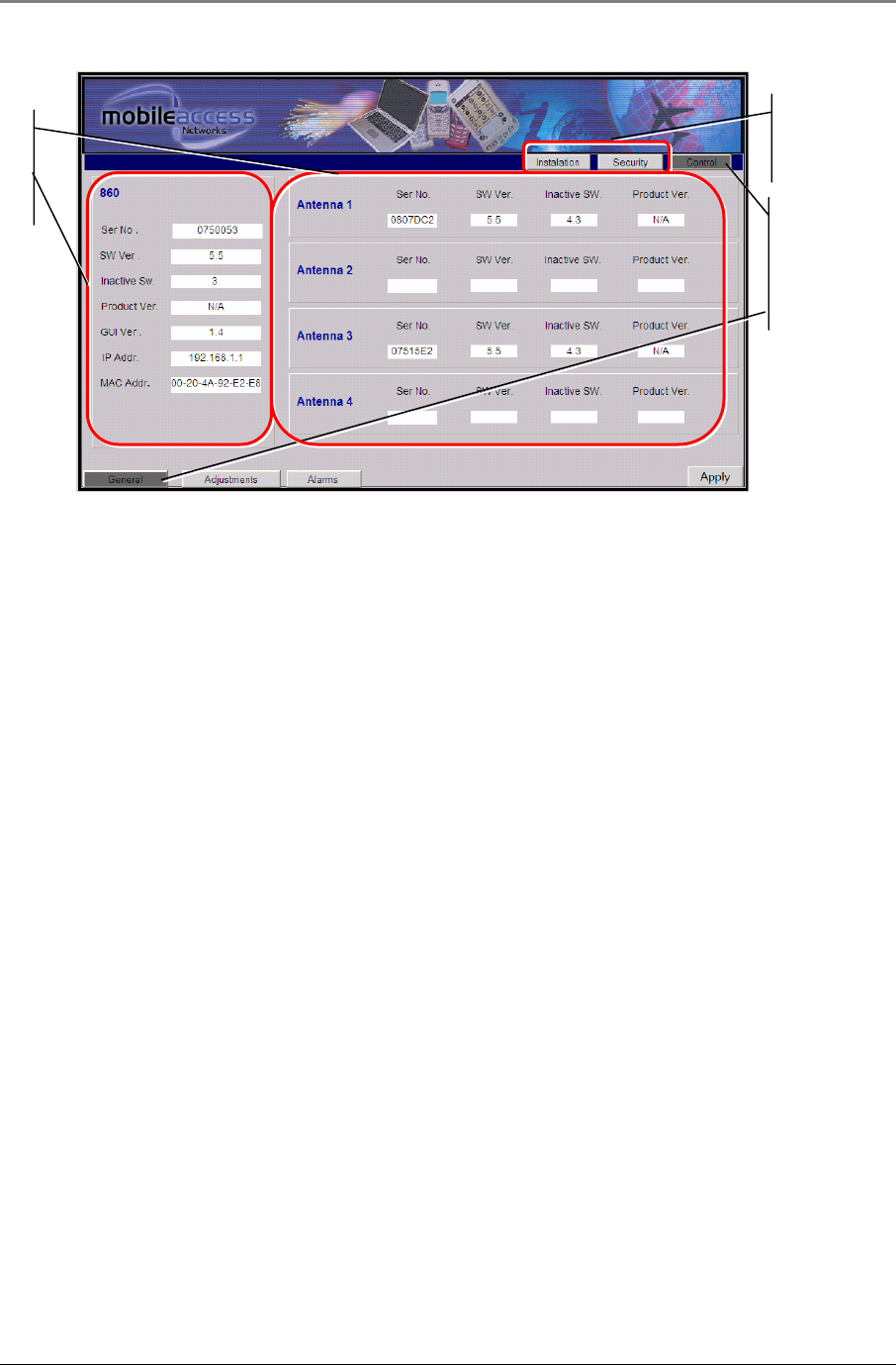
MA-860 WLAN Solution Graphical User Interface (GUI)
MA860 Installation and Configuration Guide 39
Figure 4–2: 860M/R GUI Control Screen – General Tab
4.3.2 Adjustments Tab Information
Purpose The purpose of the Adjustments tab is to provide the user with the ability to view
the cable compensation information for each antenna port.
Information Provided The following information is provided for each antenna port of the 860M/R:
1 DC: This states whether DC power is being supplied to the WCE on the port
from the 860M/R. If a WCE is discovered on the port of the 860M/R, this
value will be ON.
2 802.11a Power and 802.11b/g Power
a. Adjust a or Adjust b/g
i. If this button is pressed, the user manually forces cable
compensation to occur. By default, the 860M/R will continue to
automatically perform cable compensation as described in Section
5.1.
ii. The compensation result will be within +/-1dB of the detected input
power of the AP at the time this button is enabled.
b. AP
X
Pwr
i. This is the AP input power seen by the 860M/R on the 802.11a or
802.11b/g port associated with the antenna port, where
X
is the
antenna port number.
ii. Note that the 860M/R is not a power meter but merely a power
sensor that senses the AP input power in order to compensate for
the cable path losses between the 860M/R antenna port to the
WCE.
c. Ant
X
Pwr
i. This is the output power of the WCE associated with the antenna
port, where
X
is the antenna port number.
ii. This value should be within +/-1 dB of the AP
X
Pwr.
Only
available for
Username
FieldEng
Highlighted
to show
which GUI
screen is
shown.
MA-860
H/W and
S/W
Information

MA-860 WLAN Solution Graphical User Interface (GUI)
MA860 Installation and Configuration Guide 40
iii. Note that the 860M/R is not a power meter but merely a power
sensor that senses the AP input power in order to compensate for
the cable path losses between the 860M/R antenna port to the
WCE.
3 Full Discovery
a. Enabling this button polls each antenna port on the 860M/R in order to
find out if a WCE is connected.
b. This process also recovers the Serial Number of the WCE and updates
the pertinent information in the Antenna section of the General Tab
(refer to Figure 4–2).
c. If a WCE is replaced, this button should be pressed to discover the serial
number of the new WCE.
4 Partial Discovery
a. Enabling this button polls only the antenna ports on the 860M/R that do
not have a WCE connected to it.
b. This process also recovers the Serial Number of the WCE and updates
the pertinent information in the Antenna section of the General Tab
(refer to Figure 4–2).
c. If a WCE is connected to an unconnected port on the 860M/R, this
button should be pressed to discover the serial number of the new WCE.
5 Reset
a. Enabling this button recycles power on the 860M/R.
User Level Access Operator and Field Eng.
Adjustable Parameters 1 DC: The user can manually enable/disable power to the WCE
2 802.11a and 802.11b/g Adjust Buttons: Force cable compensation.
3 Full and Partial Discovery: Poll antenna ports to discover WCEs.
4 Reset: Recycle power of 860M/R.
5 Apply: This button is not enabled on this screen
Reference Figure Figure 4–2
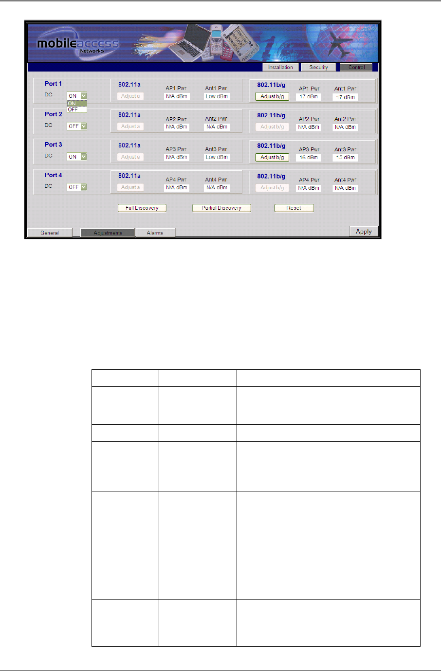
MA-860 WLAN Solution Graphical User Interface (GUI)
MA860 Installation and Configuration Guide 41
Figure 4–3: 860M/R GUI Control Screen – Adjustments Tab
4.3.3 Alarms Tab Information
Purpose The purpose of the Alarms tab is to provide the user with the ability to view the
status of the communication and hardware functionality of the 860M/R and WCE.
Information Provided Refer to Table 16 below for an explanation of the alarm features on this screen:
Name Value Comment
Trap Select Enable/Disable
Allows the user to mask/unmask traps of a
specific antenna port. Factory default is
Enable.
Temp Green Green
AP a
AP b/g Red/green
Indication per each AP port
Red – AP is not detected on this port
Green - AP is detected
MA860 WCE Red/Green/Gray
Indication per each Antenna port
Gray – WCE was not discovered on this port
Red – WCE was discovered on this port
using full/partial discovery but is not
comminuting with MA860-HU
Green - WCE was discovered on this port
using full/partial discovery and comminuting
with MA860-HU
WCE antenna Red/Green/Gray
Indication per each Antenna port
Gray – WCE was not discovered on this port
Red – Antenna was not discovered by WCE
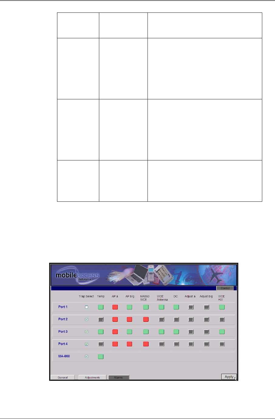
MA-860 WLAN Solution Graphical User Interface (GUI)
MA860 Installation and Configuration Guide 42
on this port
Green - Antenna was discovered by WCE on
this port
DC Red/Green
Indication per each antenna port:
Gray – No WCE was discovered on this port;
DC is off.
Red – WCE was discovered on this port
;The DC is off due to current overload.
Green – WCE was discovered on this port ;
The DC is on
Adjust a
Adjust b/g Red/Green/Gray
Indication per each Antenna port
Gray – WCE gain control procedure was not
performed
Red – WCE gain control procedure of
channel failed
Green - WCE gain control procedure of
channel successful
WCE HW Red/Green/Gray
Indication per each Antenna port
Gray – WCE was not discovered on this port
Red – WCE HW failed
Green – WCE HW O.K
Table 16: 860M/R Control Screen - Alarm Information
User Level Access Operator and Field Eng.
Adjustable
Parameters Trap Selection
Reference Figure Figure 4–4
Figure 4–4: 860M/R GUI Control Screen – Alarms Tab
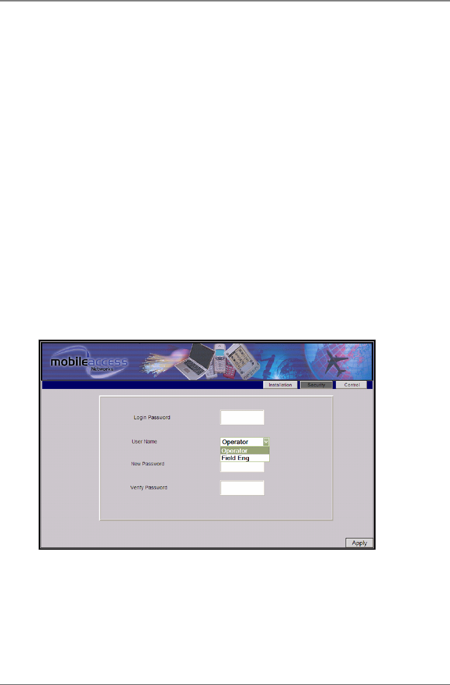
MA-860 WLAN Solution Graphical User Interface (GUI)
MA860 Installation and Configuration Guide 43
4.4 Security Screen Information
The Security button on the General Tab of the GUI provides users access to the following information:
Purpose The purpose of the Security Information screen on the General Tab is to provide
the user with the ability to change the login passwords.
Information Provided
This screen allows the user to change the Login Password as follows:
1 Enter the current Login Password for the username Field Eng.
2 Select the User Name whose Login Password is to be changed.
3 Enter the new Login Password for the User Name entered in Step 2 in the
“New Password” field
4 Verify the new Login Password in the “Verify Password” field
5 Click the “Apply” button to record change and wait for the notice to display if
the New Password is accepted.
6 The New Password should be used the next time the GUI is accessed.
User Level Access
Field Eng.
Reference Figure Figure 4–5
Figure 4–5: 860M/R GUI Security Screen
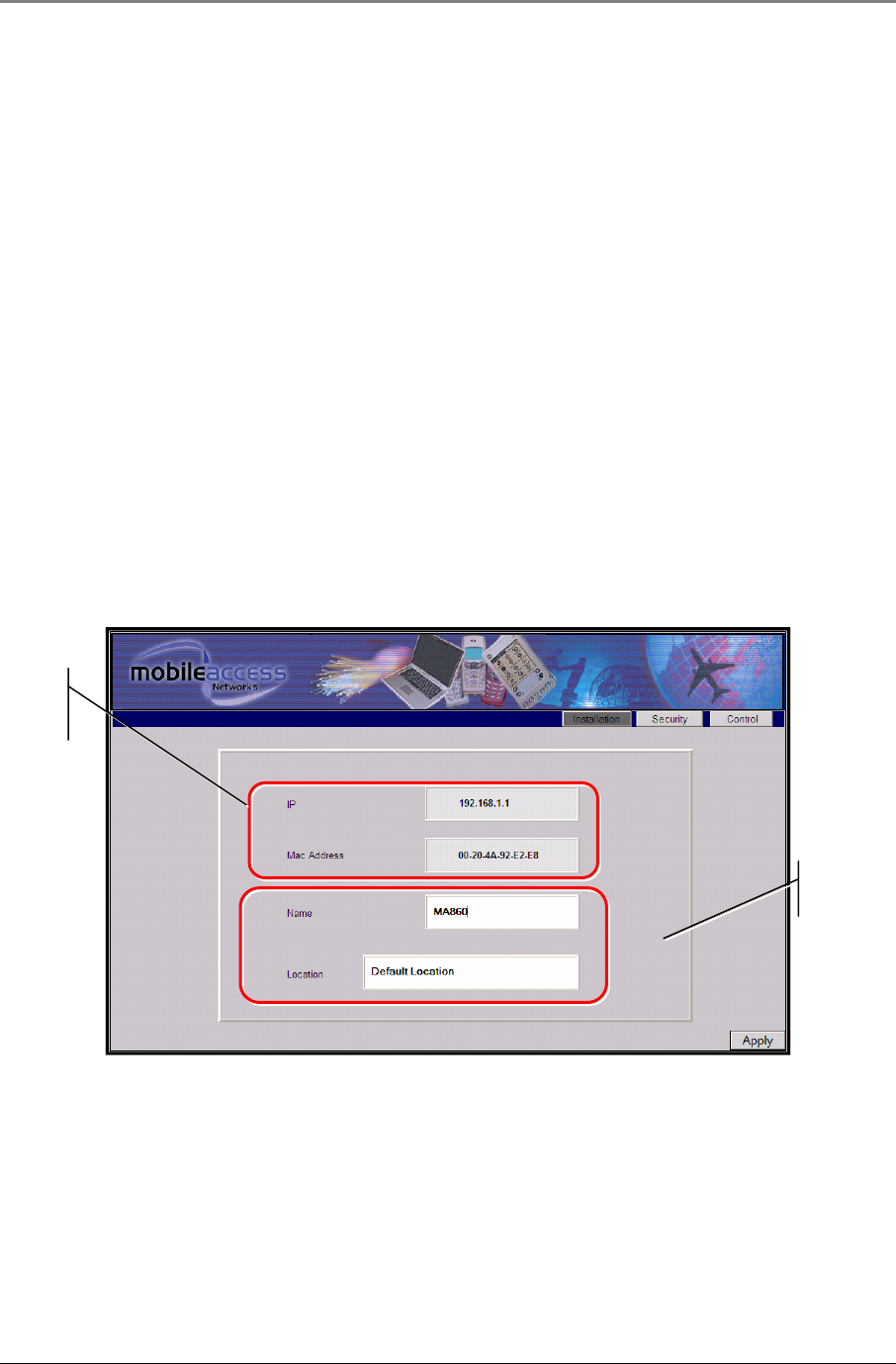
MA-860 WLAN Solution Graphical User Interface (GUI)
MA860 Installation and Configuration Guide 44
4.5 Installation Screen Information
The Installation button on the General Tab of the GUI provides users access to the following information:
Purpose The purpose of the Installation Information screen on the General Tab is to
provide the user with information on the IP, MAC, Name and Location of the
860M/R.
Information Provided
1 IP Address of 860M/R unit
2 MAC Address of Unit
3 Name of 860M/R: This can be updated by the user by entering the
information and clicking Apply.
4 Location of 860M/R: This can be updated by the user by entering the
information and clicking Apply.
User Level Access
Field Eng.
Reference Figure Figure 4–6
Figure 4–6: 860M/R GUI Installation Screen
Adjustable
Parameters
Not
Adjustable
via Web GUI

Appendix
MA860 Installation and Configuration Guide 45
5 A
Ap
pp
pe
en
nd
di
ix
x
This appendix provides information on:
• MA-860 Cable Compensation Feature
• Monitoring the unit via a third party SNMP application
• Recovering the Network Settings of an 860M/R
5.1 MA-860 Cable Compensation Feature
The MA-860 system provides a method to compensate for the RF path loss for the 802.11a/b/g
signals from the 802.11a/b/g AP ports on the 860M/R to the antenna port on the WCE. This
allows the MA-860 to mimic the “AP-on-Ceiling” deployment of a standalone WLAN installation.
The MA-860 is able to compensate for the RF path loss by adjusting the transmit and receive
gain level of the 802.11a/b/g signal at the output of the WCE. This adjustment can be made
manually or automatically as follows:
Automatic Gain Control (AGC): By default, the MA-860 is configured to automatically adjust
the gain of the WCE based on the AP input power. The MA-860 continuously compares the gain
value of the WCE output to the input power of the AP and if, over 2 minute, the delta between
the two exceeds 2dB, adjustments are made to allow the delta to become 0dB.
NOTE: When the AP is first connected to MA-860, it may take between 2-5 minutes for the initial
gain adjustment to occur. Once this is completed, the AGC will resume updating every 2
minutes.
Manual Gain Adjustment: If it is necessary to adjust the gain within the 2 minute automatic
interval, the user has the ability to manually force an adjustment. This can be done by
accessing the MA-860 GUI Adjustments tab and clicking the corresponding Adjust button as
described in Section 4.3.2.
5.2 SNMP Management Using a Standard SNMP Manager
The 860M/R packages provide MIBs that enable standard SNMP (Version 2.0) managers such as HP OpenView to
view event traps sent by the 860M/R unit.
These traps provide a general indication of the type of failure. The 860M/R enables identifying the source of the
problem and system monitoring parameters.
SNMP trap destinations and community names can be defined by following the procedure outlined in Section
3.5.3 - Setting SNMP Parameters.

Appendix
MA860 Installation and Configuration Guide 46
5.2.1 Traps List
The following traps are provided to the SNMP destination address defined by following the procedure in Section
3.5.3:
Name Type Severity OID Description
ma860powerUp NOTIFICATION-TYPE notification 81.4.2.0.1
System On.
ma860SerialNotify
NOTIFICATION-TYPE notification 81.4.2.0.2
serial communication status
failed success
ma860WceOverTemperature NOTIFICATION-TYPE major 81.4.2.0.3
WCE Temperature over 60̊ C
ma860WceNormalTemperature NOTIFICATION-TYPE info 81.4.2.0.4
WCE Temperature Normal
ma860APaDisconnect NOTIFICATION-TYPE
major 81.4.2.0.5
AP type 802.11 a
DisConnected
ma860APaDetected NOTIFICATION-TYPE
info 81.4.2.0.6
AP type 802.11 a Connected
ma860APbgDisconnect NOTIFICATION-TYPE
major 81.4.2.0.7
AP type 802.11 bg
DisConnected
ma860APbgDetected NOTIFICATION-TYPE
info 81.4.2.0.8
AP type 802.11 bg Connected
ma860WceDisconnected NOTIFICATION-TYPE
major 81.4.2.0.9
WCE Disconnected
ma860WceDetected NOTIFICATION-TYPE
info 81.4.2.0.10
WCE detected by MA860
ma860WceDCFault NOTIFICATION-TYPE
major 81.4.2.0.11
DC OFF - disconnected by
system due to falure
ma860WceDCOn NOTIFICATION-TYPE
info 81.4.2.0.12
DC ON
Ma860adjust11aFailed NOTIFICATION-TYPE
minor 81.4.2.0.13
Adjustment on type 802.11 a
Failed
Ma860adjust11aSuccess NOTIFICATION-TYPE
info 81.4.2.0.14
Adjustment on type 802.11 a
Succeeded
Ma860adjust11bgFailed NOTIFICATION-TYPE
minor 81.4.2.0.15
Adjustment on type 802.11 bg
Failed
Ma860adjust11bgSuccess NOTIFICATION-TYPE
info 81.4.2.0.16
Adjustment on type 802.11 bg
Succeeded
ma860OverTemperature NOTIFICATION-TYPE
major 81.4.2.0.17
MA860 Temperature over 60̊ C
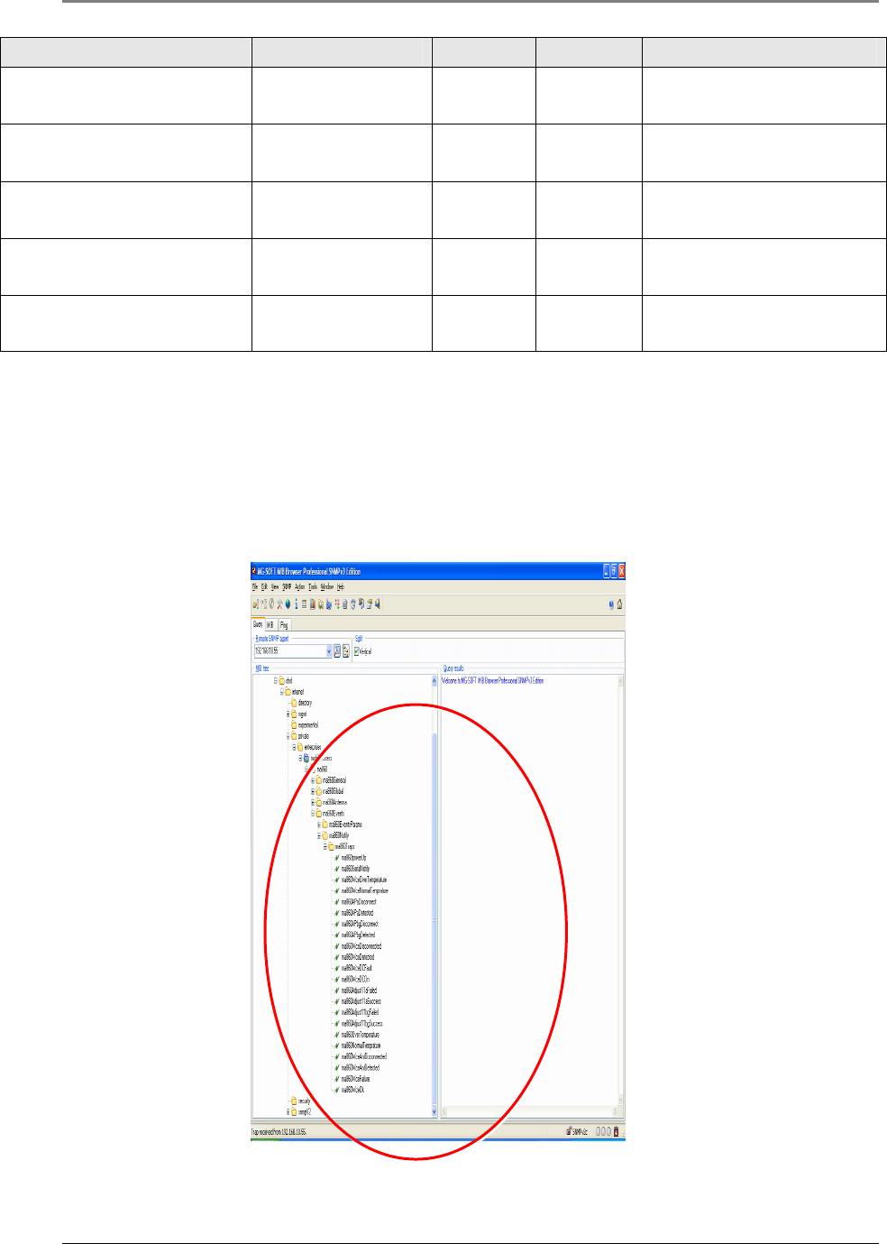
Appendix
MA860 Installation and Configuration Guide 47
Name Type Severity OID Description
ma860NormalTemperature NOTIFICATION-TYPE
info 81.4.2.0.18
MA860 Temperature Normal
ma860WceAntDisconnected NOTIFICATION-TYPE
major 81.4.2.0.19
WCE antenna
DisConnected
ma860WceAntDetected NOTIFICATION-TYPE
info 81.4.2.0.20
WCE antenna Connected
ma860WceFailure NOTIFICATION-TYPE
major 81.4.2.0.21
WCE HW failure
ma860WceOK NOTIFICATION-TYPE
info 81.4.2.0.22
WCE HW OK
Table 17: MA860 WLAN Solutuion SNMP Trap Definitions
5.2.2 Viewing and Configuring Using a Standard MIB Browser
To view and configure using any standard SNMP manager such as MG-Soft MIB Browser. It is assumed that the
IP Address of at least one trap destination is already defined (refer to Section 3.5.3).
From a computer
configured as a trap destination
(configured to receive the traps), load the MIB file to the
SNMP manager. The following figure shows the MIB tree that includes the loaded MobileAccess™ MA 860 file.
Figure 5–1. MIB Tree with Loaded MobileAccess™ MA 860

Appendix
MA860 Installation and Configuration Guide 48
5.3 860M/R Network Configuration Recovery Procedure
If the network configuration of the 860M/R unit (e.g. IP address, netmask, etc.) has been forgotten or lost, use
Address Resolution Protocol (ARP) method from UNIX and Windows-based systems to assign a temporary IP
address as described in this section.
Follow the steps below to assign a new IP address to the 860M/R module. In the steps below, the example is
used to configure an 860M/R which has a MAC of 00-20-4a-91-FD-18, with an IP address of 192.168.1.1 and a
subnet of 255.255.255.0. Refer to Figure 5–2 and Figure 5–3, which show the example on a Windows PC.
1. Power on the 860M/R unit if not already powered.
2. Disconnect the 860M/R from the customer LAN.
3. Connect the PC to the 860M/R Ethernet port via a cross over cable.
4. Establish a static IP on the PC that is on the same network that the 860M/R unit is to be on. As per the
example, the PC is set to an address of 192.168.1.3 with a subnet of 255.255.255.0.
5. Open a command prompt on the PC.
6. Create an entry in the host's ARP table using the intended IP address (e.g. 192.168.1.1) and the MAC
address of the unit (e.g. 00-20-4a-91-FD-18) (on the product label on the bottom of the unit) as shown
below:
7. For a Unix based PC enter:
>
arp -s 192.168.1.1 00:20:4a:91:FD:18
8. For a Windows based PC enter:
>
arp -s 192.168.1.1 00-20-4a-91-FD-18
9. Confirm the entry into the host’s ARP table by typing in the following command at the command prompt:
>
arp –a
10. Open a Telnet connection to port 1 by typing in the following command (The connection fails quickly, but
the unit temporarily changes its IP address to the one designated in this step)
>
telnet 192.168.1.1 1
11. Open a Telnet connection to port 9999, and press Enter to go into Setup Mode within 5 seconds otherwise,
connection to the host is lost. If this occurs, open up another command prompt and repeat this step.
>
telnet 192.168.1.1 9999
Figure 5–2: Recover 860M/R Network Configuration Steps 6-11
12. Select 0 (Server Configuration).
13. Enter the new IP address, subnet mask, and gateway (if applicable).
14. Select 9 to save and exit Setup Mode.
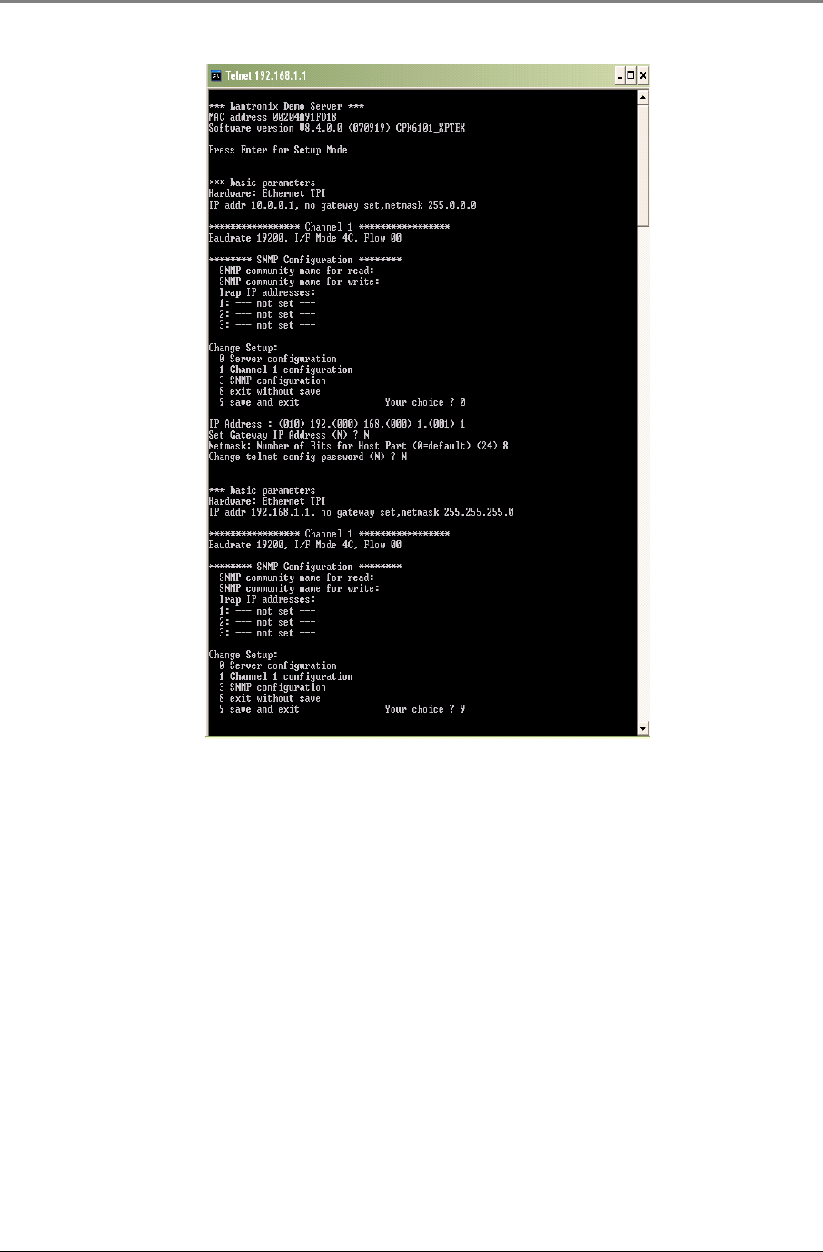
Appendix
MA860 Installation and Configuration Guide 49
15. Once the above steps are completed, the 860M/R can be connected back to the LAN
Figure 5–3: Recover 860M/R Network Configuration Steps 10-15
5.4 NMS Management and Configuration
If your coverage network includes other MobileAccess™ systems (such as MA1000 or MA2000) that are managed
via NMS, you may also use the NMS to remotely manage and monitor MA860 devices to which an IP address has
been assigned.
The MA860 graphical interface, management and monitoring windows that are accessed via the NMS are
identical to the WEB Access windows described in the previous section.
For more explanations about using the NMS Management application see the
MA NMS 410/430 System
Installation and Configuration Guide.
In order to configure for discovery of 860M/R devices, it is required to configure the IP of the devices in the
Network Topology tree.
Steps to configure the monitoring of 860M/R via NMS are described below:
1. Select the wanted branch under which a new node will be configured and click the Add button. The Add
pane is invoked. Choose Node. Refer to Figure 5–4.
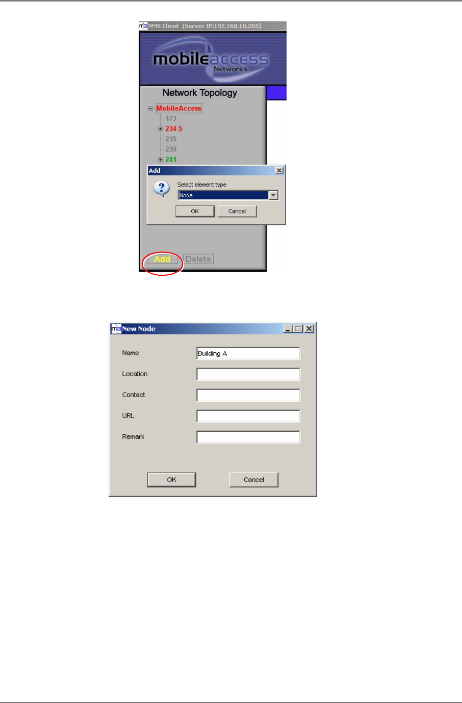
Appendix
MA860 Installation and Configuration Guide 50
Figure 5–4: NMS Client - Add Node
2. In the invoked New Node pane insert the node details and click OK. Refer to Figure 5–5.
Figure 5–5: NMS Client - New Node
3. The new node is added to the Network Topology tree. In this example, four nodes were added: “Building A”
and under it “Floor-4”, “Floor-5” and “Floor-6”. Refer to Figure 5–6.
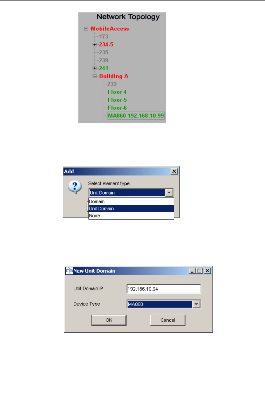
Appendix
MA860 Installation and Configuration Guide 51
Figure 5–6: NMS Client - Network Topology
4. Under every node an MA860 device(s) can be added by selecting the wanted node and clicking the Add
button to invoke the Add pane.
5. In the Add pane, choose Element Type Unit Domain as shown in Figure 5–7.
Figure 5–7: NMS Client - Select Element Type to Add
In the invoked Add pane choose the Unit Domain option.
6. In the New Unit Domain configuration pane choose the device type (MA860) and insert the exact IP address
of the 860M/R unit as shown in Figure 5–8.
Figure 5–8: NMS Client - Enter 860M/R Information
7. After clicking OK, the corresponding device will appear in the Network Topology tree, under the selected
node. To view the MA860 double click it in order to open the GUI described in Section 4 . Refer to Figure
5–9 which shows two MA-860 defined under the “Floor-5” node:

Appendix
MA860 Installation and Configuration Guide 52
Figure 5–9: NMS Client - MA-860 Added to Network Topology