Corning Optical Communication MODULITE810 WLAN In-Building Access Point Amplifier User Manual ModuLiteInstallGuide 439300505 y
Corning Optical Communication Wireless WLAN In-Building Access Point Amplifier ModuLiteInstallGuide 439300505 y
Revised user manual
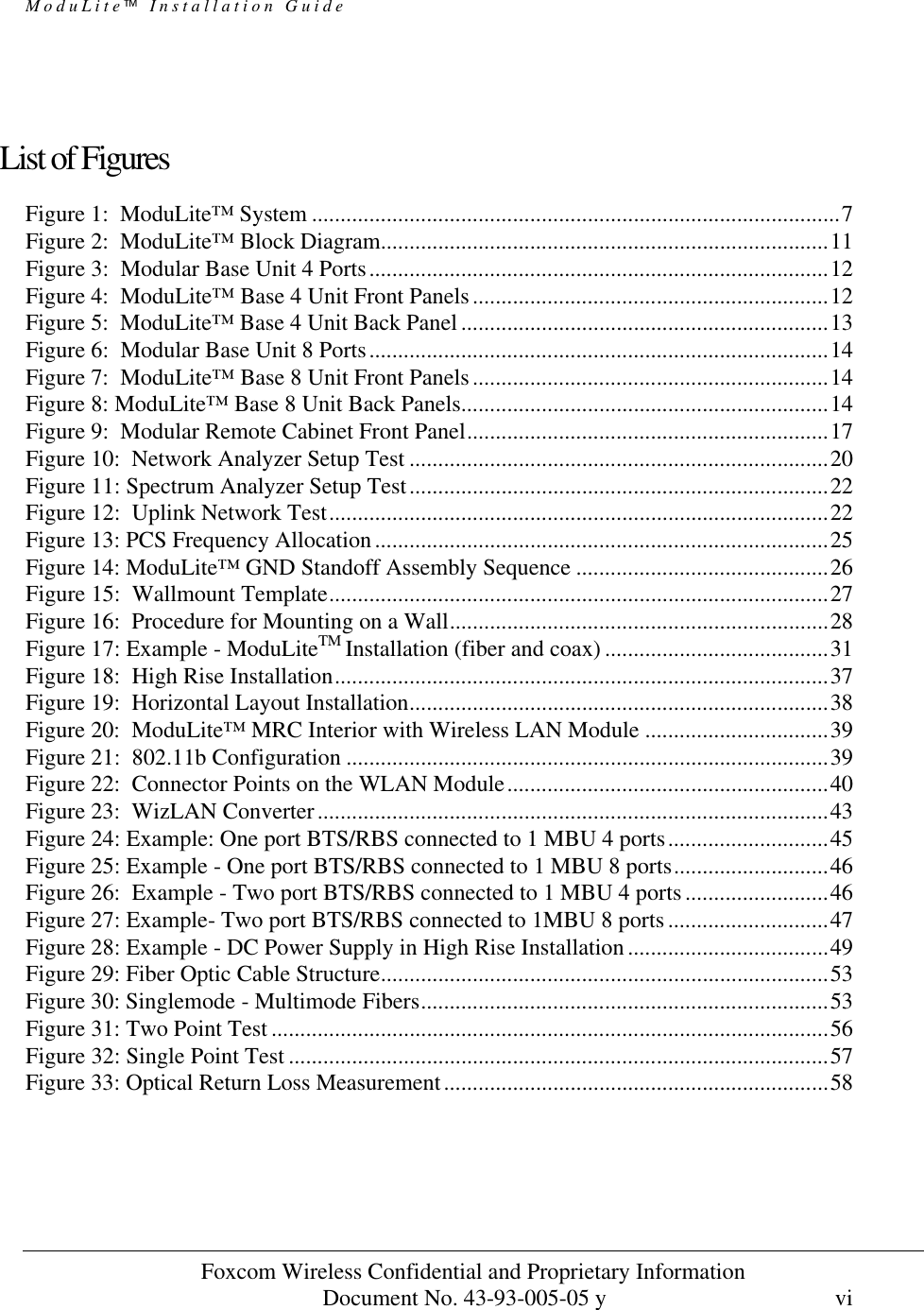
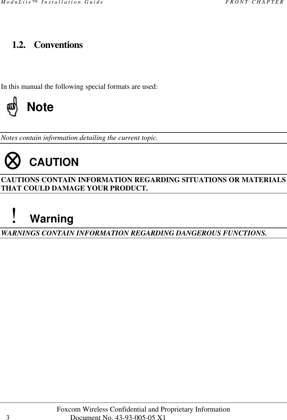
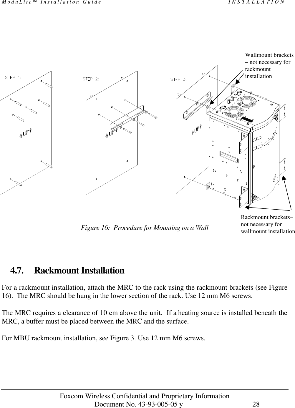
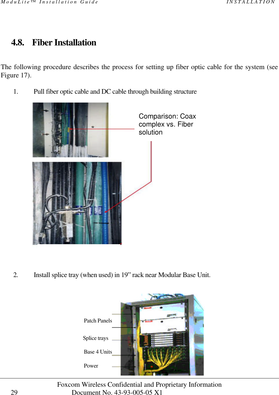
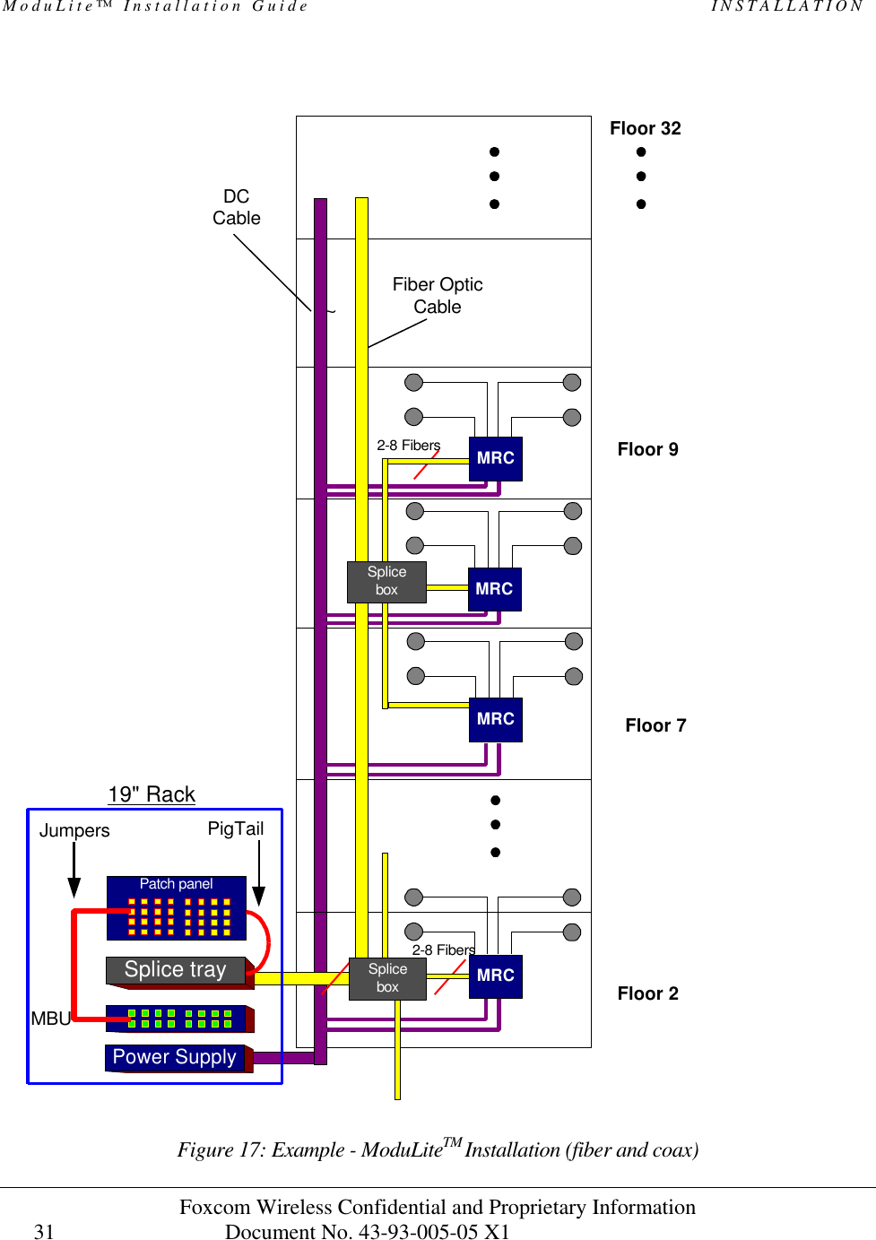
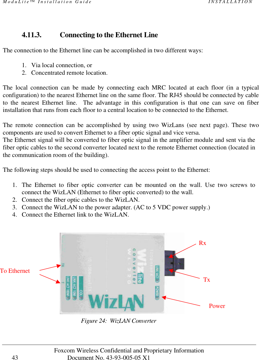
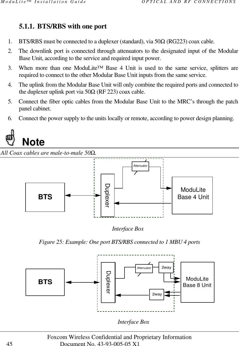
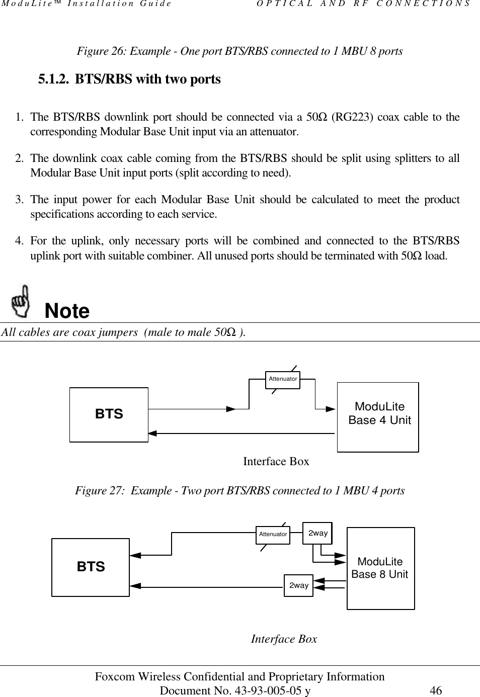
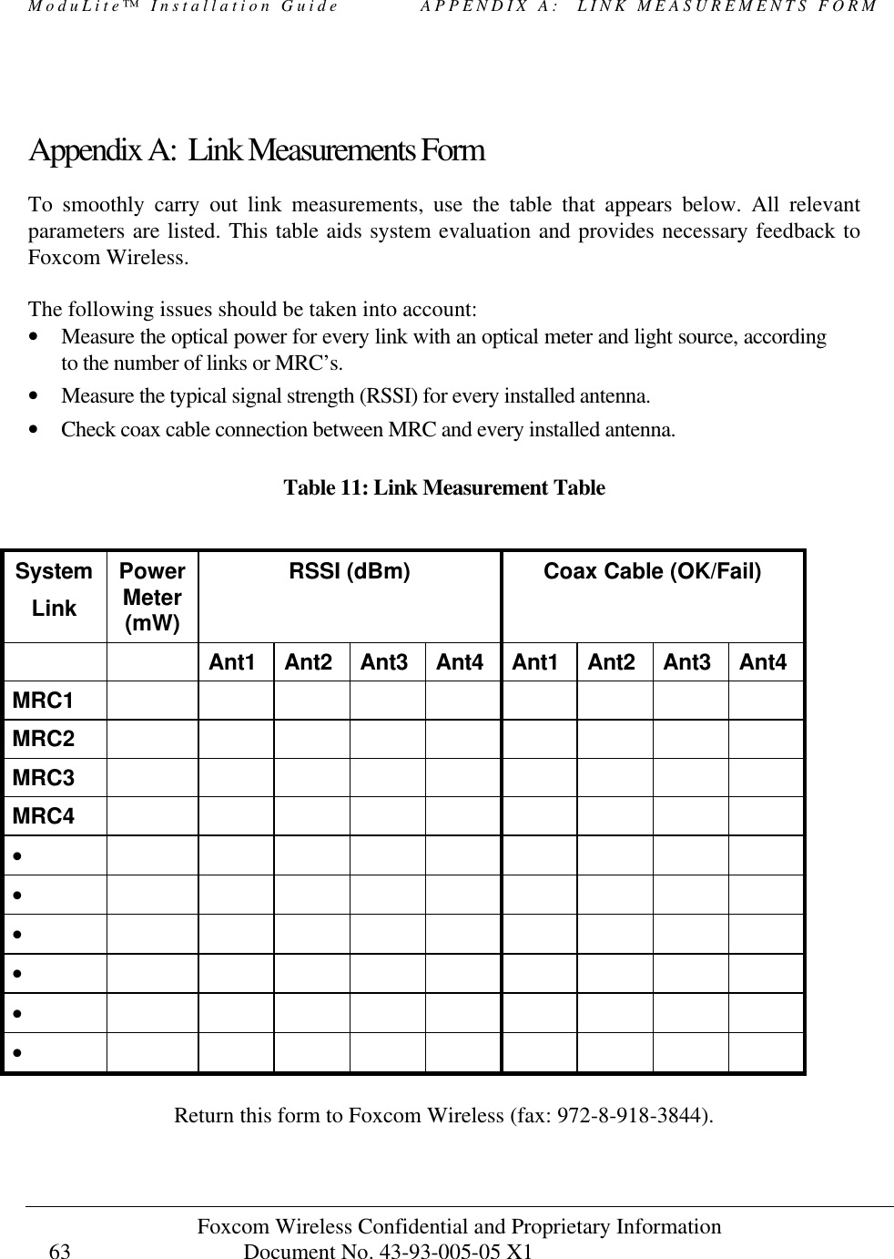
![ModuLite Installation Guide INSTALLATION Foxcom Wireless Confidential and Proprietary Information Document No. 43-93-005-05 y 42 # of Access Points Access point designator Connected to Antenna 1 AP 1 1,2,3,4 2 AP1 1,2 AP2 3,4 3 AP1 1,2 AP2 3 AP3 4 4 AP1 1 AP2 2 AP3 3 AP4 4 Indoor Wide band Antennas Combining the Cellular and the WLAN services requires using wide band antennas. Attached are the recommended antennas tested and approved by Foxcom Wireless. Vendor Catalog number Gain [dBi] Mars Antennas MA-CM36-15 2 low band 3-4 high band 5 WLAN 802.11b Celwave A08818DC00-28T0 2.1 Antenna ASP-3561 2](https://usermanual.wiki/Corning-Optical-Communication/MODULITE810/User-Guide-325101-Page-52.png)