Corning Optical Communication MODULITE810 WLAN In-Building Access Point Amplifier User Manual ModuLiteInstallGuide 439300505 y
Corning Optical Communication Wireless WLAN In-Building Access Point Amplifier ModuLiteInstallGuide 439300505 y
Revised user manual

Installation Guide
Copyright Foxcom Wireless 200
Notice
© 200 by Foxcom Wireless
This document contains confidential and proprietary information of Foxcom Wireless and
may not be copied, transmitted, stored in a retrieval system or reproduced in any format or
media, in whole or in part, without the prior written consent of Foxcom Wireless. Information
contained in this document supersedes any previous manuals, guides, specifications, data
sheets or other information that may have been provided or made available to the user. This
document is provided for informational purposes only, and Foxcom Wireless does not warrant
or guarantee the accuracy, adequacy, quality, validity, completeness or suitability for any
purpose of the information contained in this document. Foxcom Wireless reserves the right to
make updates, improvements and enhancements to this document and the products to which it
relates at any time without prior notice to the user. FOXCOM WIRELESS MAKES NO
WARRANTIES, EXPRESS OR IMPLIED, INCLUDING, WITHOUT LIMITATION,
THOSE OF MERCHANTABILITY AND FITNESS FOR A PARTICULAR PURPOSE,
WITH RESPECT TO THIS DOCUMENT OR ANY INFORMATION CONTAINED
HEREIN.
Trademark Acknowledgement
LitennaTM and RFiberTM and ModuLite™ are registered trademarks of Foxcom Wireless. This
document contains other trademarks, trade names and service marks of Foxcom Wireless and
other organizations, all of which are the property of their respective owners.

Foxcom Wireless Confidential and Proprietary Information
Document No. 43-93-005-05 X1 iii
Foxcom Wireless Offices
ISRAEL - HEADQUARTERS
USA
Foxcom Wireless Ltd.
Foxcom Wireless Inc.
Tel: 972-8-918-3888 Tel: 1-866-4-FOXCOM

ModuLite™ Installation Guide
Foxcom Wireless Confidential and Proprietary Information
Document No. 43-93-005-05 X1 iii
Table of Contents
1. Front Chapter 1
1.1. Policy for Warranty and Repair 1
1.2. Conventions 3
1.3. Reporting Defects 4
1.4. RF Exposure Compliance 4
1.5. Precautions 5
1.5.1. Personal Safety 5
1.5.2. Equipment Safety 6
1.5.3. System Performance 6
1.5.4. Power Supply 6
2. Introduction to the ModuLite™ 7
2.1. Applications 8
2.2. Models 9
2.2.1. Certification 10
2.2.2. System Description 11
2.3. Product Drawings 12
2.3.1. Modular Base Unit- Four Ports 12
2.3.2. Modular Base Unit- Eight Ports 14
2.3.3. Modular Remote Cabinet (dimensions in millimeters) 15
2.3.3.1. Isometric View 15
2.3.3.2. Front and Side View 15
2.3.3.3. Top View 16
2.3.3.4. Back View 16
2.3.3.5. Module Front Panel 17
3. Setup Tests 18
3.1. Pre RF Test 19
3.2. Flatness Test 20
3.3. Gain/IP3 Test 21
3.4. Uplink Network Test 22
4. Installation 23
4.1. General Installation 23
4.2. Environmental Data 24
4.3. Configuration Restrictions 25

ModuLite Installation Guide
Foxcom Wireless Confidential and Proprietary Information
Document No. 43-93-005-05 y iv
4.4. Environmental Data 25
4.5. Protective Earthing 26
4.6. Wallmount Installation 26
4.7. Rackmount Installation 28
4.8. Fiber Installation 29
4.8.1. Fiber Optic Cable 32
4.8.2. ModuLite™ Installation Parts List 35
4.9. High Rise Installation 37
4.10. Horizontal Layout Installation 38
4.11. Wireless LAN Installation 38
4.11.1. System Configuration with Modulite 810 39
4.11.2. System configuration with 840 41
4.11.3. Connecting to the Ethernet Line 43
5. Optical and RF Connections 44
5.1. Modular Base Unit (MBU) 44
5.1.1. BTS/RBS with one port 45
5.1.2. BTS/RBS with two ports 46
5.2. Modular Remote Cabinet (MRC) 47
6. Alarm Monitoring 48
7. Power Supply for ModuLite™ 49
7.1. Option One (Remote Power) 50
7.2. Option Two (Local Powering) 50
7.3. Option Three (Built-In Powering) 50
8. Optical Test Procedure 51
8.1. Fiber Optic Cable Test 51
8.2. Fiber Optic Cable – Terms 51
8.2.1. Optical Fiber 52
8.2.2. Connecting Fiber Optic Cable 54
8.2.3. Fiber Optic Cable Bending Loss 54
8.2.4. Coupler 54
8.3. Foxcom Wireless System Characteristics 55
8.3.1. Test Equipment 55
8.4. Optical Insertion Loss Measurement Test 56
8.4.1. Method #1: Two Point Test 56

ModuLite™ Installation Guide
Foxcom Wireless Confidential and Proprietary Information
Document No. 43-93-005-05 X1 v
8.4.2. Method #2: Single Point Test 57
8.4.3. Other Test Equipment 57
8.5. Optical Return Loss Measurement Test 58
8.5.1. Measurement Procedure 58
8.6. Results 59
8.7. Summary 59
9. Final Test 60
9.1. Modular Base Unit and Modular Remote Cabinet Connections 60
10. Maintenance / Mechanical Adjustment 61
11. Troubleshooting 61
Appendix A: Link Measurements Form 63

ModuLite Installation Guide
Foxcom Wireless Confidential and Proprietary Information
Document No. 43-93-005-05 y vi
List of Figures
Figure 1: ModuLite™ System ............................................................................................7
Figure 2: ModuLite™ Block Diagram..............................................................................11
Figure 3: Modular Base Unit 4 Ports................................................................................12
Figure 4: ModuLite™ Base 4 Unit Front Panels..............................................................12
Figure 5: ModuLite™ Base 4 Unit Back Panel ................................................................13
Figure 6: Modular Base Unit 8 Ports................................................................................14
Figure 7: ModuLite™ Base 8 Unit Front Panels..............................................................14
Figure 8: ModuLite™ Base 8 Unit Back Panels................................................................14
Figure 9: Modular Remote Cabinet Front Panel...............................................................17
Figure 10: Network Analyzer Setup Test .........................................................................20
Figure 11: Spectrum Analyzer Setup Test.........................................................................22
Figure 12: Uplink Network Test.......................................................................................22
Figure 13: PCS Frequency Allocation...............................................................................25
Figure 14: ModuLite™ GND Standoff Assembly Sequence ............................................26
Figure 15: Wallmount Template.......................................................................................27
Figure 16: Procedure for Mounting on a Wall..................................................................28
Figure 17: Example - ModuLiteTM Installation (fiber and coax) .......................................31
Figure 18: High Rise Installation......................................................................................37
Figure 19: Horizontal Layout Installation.........................................................................38
Figure 20: ModuLite™ MRC Interior with Wireless LAN Module ................................39
Figure 21: 802.11b Configuration ....................................................................................39
Figure 22: Connector Points on the WLAN Module........................................................40
Figure 23: WizLAN Converter.........................................................................................43
Figure 24: Example: One port BTS/RBS connected to 1 MBU 4 ports............................45
Figure 25: Example - One port BTS/RBS connected to 1 MBU 8 ports...........................46
Figure 26: Example - Two port BTS/RBS connected to 1 MBU 4 ports.........................46
Figure 27: Example- Two port BTS/RBS connected to 1MBU 8 ports............................47
Figure 28: Example - DC Power Supply in High Rise Installation...................................49
Figure 29: Fiber Optic Cable Structure..............................................................................53
Figure 30: Singlemode - Multimode Fibers.......................................................................53
Figure 31: Two Point Test .................................................................................................56
Figure 32: Single Point Test ..............................................................................................57
Figure 33: Optical Return Loss Measurement...................................................................58

ModuLite™ Installation Guide FRONT CHAPTER
Foxcom Wireless Confidential and Proprietary Information
Document No. 43-93-005-05 X1 vii
List of Tables
Table 1: ModuLite™ Models .............................................................................................9
Table 2: Modular Base Unit Description...........................................................................13
Table 3: Modular Remote Cabinet Description................................................................17
Table 4: Required Equipment List....................................................................................18
Table 5: ModuLiteTM Installation Parts List ......................................................................35
Table 6: ModuLite™ Installation Labor List.....................................................................36
Table 7: 25 Pin Alarm Pinouts ..........................................................................................48
Table 8: Power Supply Options.........................................................................................50
Table 9: Fiber Optic Cable Test Results...........................................................................59
Table 10: Optical LED States ............................................................................................61
Table 11: Link Measurement Table...................................................................................63

ModuLite™ Installation Guide FRONT CHAPTER
Foxcom Wireless Confidential and Proprietary Information
Document No. 43-93-005-05 X1
1
1. Front Chapter
1.1. Policy for Warranty and Repair
Foxcom Wireless tests and inspects all its products to verify their quality and reliability.
Foxcom Wireless uses every reasonable precaution to ensure that each unit meets their declared
specifications before shipment. Customers should advise their incoming inspection, assembly,
and test personnel about the precautions required in handling and testing our products. Many of
these precautions can be found in this manual.
The products are covered by the following warranties:
1. General Warranty
Foxcom Wireless warrants to the original purchaser all standard products sold by
Foxcom Wireless to be free of defects in material and workmanship for one (1) year from date of
shipment from Foxcom Wireless. During the warranty period, Foxcom Wireless will repair or
replace any product that Foxcom Wireless proves to be defective. This warranty does not apply
to any product that has been subject to alteration, abuse, improper installation or application,
accident, electrical or environmental over-stress, negligence in use, storage, transportation or
handling.
2. Specific Product Warranty Instructions
All Foxcom Wireless products are warranted against defects in workmanship, materials and
construction, and to no further extent. Any claim for repair or replacement of units found to be
defective on incoming inspection by a customer must be made within 30 days of receipt of
shipment, or within 30 days of discovery of a defect within the warranty period.
This warranty is the only warranty made by Foxcom Wireless and is in lieu of all other
warranties, expressed or implied. Foxcom Wireless sales agents or representatives are not
authorized to make commitments on warranty returns.

ModuLite Installation Guide FRONT CHAPTER
Foxcom Wireless Confidential and Proprietary Information
Document No. 43-93-005-05 y 2
3. Returns
In the event that it is necessary to return any product against above warranty, the following
procedure shall be followed:
a. Return authorization is to be received from Foxcom Wireless prior to returning any unit.
Advise Foxcom Wireless of the model, serial number, and discrepancy. The unit may then
be forwarded to Foxcom Wireless, transportation prepaid. Devices returned collect or
without authorization may not be accepted.
b. Prior to repair, Foxcom Wireless will advise the customer of our test results and any
charges for repairing customer-caused problems or out-of-warranty conditions etc.
c. Repaired products are warranted for the balance of the original warranty period, or at least
90 days from date of shipment.
4. Limitations of Liabilities
Foxcom Wireless's liability on any claim, of any kind, including negligence for any loss or
damage arising from, connected with, or resulting from the purchase order, contract, quotation,
or from the performance or breach thereof, or from the design, manufacture, sale, delivery,
installation, inspection, operation or use of any equipment covered by or furnished under this
contact, shall in no case exceed the purchase price of the device which gives rise to the claim.
EXCEPT AS EXPRESSLY PROVIDED HEREIN, FOXCOM WIRELESS MAKES NO
WARRANTY, EXPRESSED OR IMPLIED, WITH RESPECT TO ANY GOODS, PARTS
AND SERVICES PROVIDED IN CONNECTION WITH THIS AGREEMENT
INCLUDING, BUT NOT LIMITED TO, THE IMPLIED WARRANTIES OF
MERCHANTABILITY AND FITNESS FOR A PARTICULAR PURPOSE.
FOXCOM WIRELESS SHALL NOT BE LIABLE FOR ANY OTHER DAMAGE
INCLUDING, BUT NOT LIMITED TO, INDIRECT, SPECIAL OR CONSEQUENTIAL
DAMAGES ARISING OUT OF OR IN CONNECTION WITH FURNISHING OF
GOODS, PARTS AND SERVICE HEREUNDER, OR THE PERFORMANCE, USE OF,
OR INABILITY TO USE THE GOODS, PARTS AND SERVICE.

ModuLite™ Installation Guide FRONT CHAPTER
Foxcom Wireless Confidential and Proprietary Information
Document No. 43-93-005-05 X1
3
1.2. Conventions
In this manual the following special formats are used:
Note
Notes contain information detailing the current topic.
CAUTION
CAUTIONS CONTAIN INFORMATION REGARDING SITUATIONS OR MATERIALS
THAT COULD DAMAGE YOUR PRODUCT.
! Warning
WARNINGS CONTAIN INFORMATION REGARDING DANGEROUS FUNCTIONS.

1.3. Reporting Defects
The units were inspected before shipment and found to be free of mechanical and
electrical defects.
Examine the units for any damage that may have been caused in transit. If damage is
discovered, file a claim with the freight carrier immediately. Notify Foxcom Wireless as
soon as possible.
Refer to Policy for Warranty and Repair for further details.
Note
Keep all packing material until you have completed the inspection.
1.4. RF Exposure Compliance
!! Warning
TO COMPLY WITH FCC RF EXPOSURE COMPLIANCE REQUIREMENTS,
ANTENNAS USED FOR THIS PRODUCT MUST BE FIXED MOUNTED ON INDOOR
PERMANENT STRUCTURES, PROVIDING A SEPARATION DISTANCE OF AT LEAST
20 CM FROM ALL PERSONS DURING NORMAL OPERATION.
ANTENNAS MUST BE SEPARATED FROM EACH OTHER, ACCORDING TO THE
SPECIFIC FCC STANDARD. FOR MODEL 810/840 ANTENNAS MUST BE MOUNTED
SO THAT THERE IS AT LEAST 2M SEPARATION BETWEEN ANY TWO ANTENNAS
!! Warning
Each individual antenna used for this transmitter must be installed to provide a minimum
separation distance of 20 cm or more from all persons and must not be co-located with
any other antenna for meeting RF exposure requirements.

ModuLite™ Installation Guide FRONT CHAPTER
Foxcom Wireless Confidential and Proprietary Information
Document No. 43-93-005-05 X1
5
1.5. Precautions
1.5.1. Personal Safety
The ModuLite™ system uses an optical laser for transmitting voice and data. The laser unit has
the following output characteristics:
• Optical output power (mW): ≤3.0
• Wavelength (nM): 1310 ± 10
! Warning
APPLYING POWER TO THE MODULAR BASE UNIT AND MODULAR REMOTE
CABINET WILL CREATE A LASER ENERGY SOURCE OPERATING IN CLASS I AS
DEFINED BY IEC 60825-1, 21 CFR 1040.10 AND 1040.11 EXCEPT FOR DEVIATIONS
PURSUANT TO LASER NOTICE NO. 50 (JULY 26, 2001). USE EITHER AN INFRARED
VIEWER, OPTICAL POWER METER OR FLUORESCENT SCREEN FOR OPTICAL
OUTPUT VERIFICATION.
! Warning
THE USE OF CONTROLS OR ADJUSTMENTS OR PERFORMANCE PROCEDURES
OTHER THAN THOSE SPECIFIED HEREIN MAY RESULT IN HAZARDOUS
RADIATION EXPOSURE.
! Warning
COMPLIANCE WITH RF SAFETY REQUIREMENTS:
THE MODULITE™ HAS NO INHERENT SIGNIFICANT RF RADIATION.
THE RF LEVEL ON THE DOWNLINK IS VERY LOW AT THE MODULAR REMOTE
CABINET DOWNLINK PORTS. THEREFORE, THERE IS NO DANGEROUS RF
RADIATION WHEN THE ANTENNA IS NOT CONNECTED.
THE DESIGN OF THE ANTENNA INSTALLATION NEEDS TO BE IMPLEMENTED IN
SUCH A WAY SO AS TO ENSURE RF RADIATION SAFETY LEVELS AND NON-
ENVIRONMENTAL POLLUTION DURING OPERATION.

ModuLite Installation Guide FRONT CHAPTER
Foxcom Wireless Confidential and Proprietary Information
Document No. 43-93-005-05 y 6
1.5.2. Equipment Safety
To avoid damaging your product, please observe the following:
1. Always keep the optical connector covered. Use the fiber optic cable or a protective cover. Do
not allow any dirt and/or foreign material to get on the optical connector bulkheads.
2. The optical fiber jumper cable bend radius is 3 cm. Smaller radii can cause excessive optical
loss and/or fiber breakage.
1.5.3. System Performance
! Warning
FOR PROPER SYSTEM PERFORMANCE USE ONLY CABLES EQUIPPED WITH
SC/APC CONNECTORS TO CONNECT TO THE FOXCOM WIRELESS MODULITE™
SYSTEM.
1.5.4. Power Supply
! Warning
DISCONNECT BOTH POWER SOURCES BEFORE SERVICING.
CAUTION
______________________________________________
______________________________________________
________________
FOR CONTINUED PROTECTION AGAINST RISK OF FIRE, REPLACE ONLY WITH
SAME TYPE AND RATINGS OF FUSES.
SC/APC Connector
ModuLite™ Installation Guide INTRODUCTION TO THE MODULITE™
Foxcom Wireless Confidential and Proprietary Information
Document No. 43-93-005-05 X1 7
2. Introduction to the ModuLite™
Infrastructure for multiple services is currently provided through two different methods. The first
method is a parallel infrastructure based on a fiber or hybrid fiber-copper solution. In this system,
even though all operators provide mutual services with a potential for sharing, a complete
infrastructure is deployed for every operator. Multiple antennas need to be installed in every
radiation zone. Isolation between antennas is hard to control, and as a result, cross antenna
interference may cause degraded performance.
The second available solution is based on coax. Coax has different attenuation levels for
different frequencies. This leads to design constraints because the coax needs to match the
highest frequencies serviced and their respective attenuation levels. This requirement leads to
higher costs resulting from the larger diameter coax and from a more labor-intensive installation.
Foxcom Wireless’s ModuLiteTM is a new approach. The ModuLite™ is a high-performance, cost
effective and modular In-Building system designed for multiple wireless services. It is
technically superior to other available infrastructures, and provides WSP’s and building
operators with an advanced platform for expansion and upgradability.
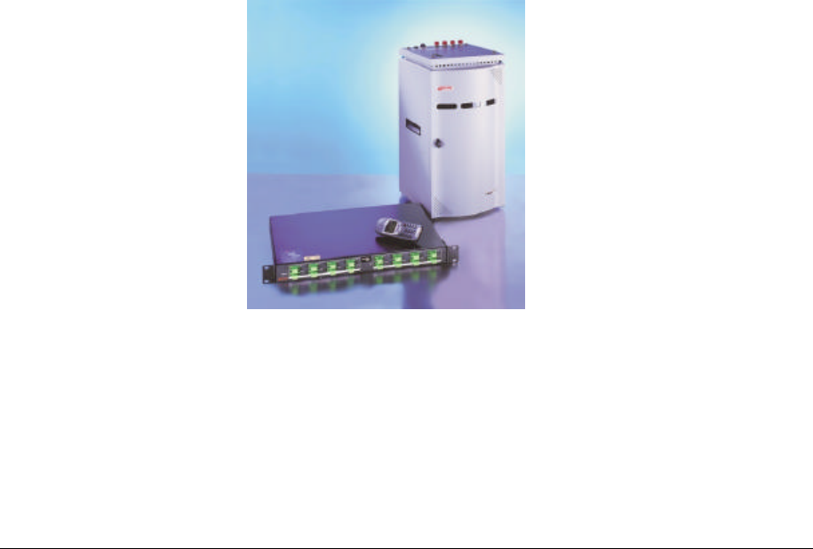
Figure 1: ModuLite™ System
The ModuLite™ has unique advantages:
• Low attenuation: Singlemode fiber optic cables have virtually no attenuation (0.38dB/Km),
relieving the need to install amplifiers or any other signal enhancing in-line devices. This factor
alone greatly reduces the engineering and installation costs.

ModuLite Installation Guide INTRODUCTION TO THE MODULITE™
Foxcom Wireless Confidential and Proprietary Information
Document No. 43-93-005-05 y 8
• Low noise: High bandwidth signals can be set over singlemode fibers without encountering
noise problems, and transmitted over great distances.
• Multi Services: Same infrastructure is used either supporting single service or multiple
services, due to the pseudo infinite bandwidth of singlemode fiber optic cable.
2.1. Applications
The ModuLite™ addresses both public and private markets in order to provide RF distribution
solutions for various structure types:
• Typical Public Market
o Malls
o Airports
o Conventions Centers
o Hospitals
• Typical Private Market
o Office Buildings
o Business Centers
o Campus
Three types of applications are very common for both markets:
• High Rise Buildings
• Horizontal Structures
• Campus type
Foxcom Wireless’ ModuLite™ addresses these application types with a powerful answer, while
still flexible and future expandable. There are no limitations for building height or structure
spread.

2. 2 Models
ModuLite™ products come in various models, each model covering a different frequency
spectrum and standard. Table 1: ModuLite™ Models
System
Configuration Service Frequency Range (MHz)
Uplink Downlink
U.S. Market Cellular/PCS 824-849;
1850-1910 869-894;
1930-1990
iDEN/PCS 806-824;
1850-1910 851-869;
1930-1990
Paging/PCS 899-902;
1850-1910 928-941;
1930-1990
WLAN/UNLICENSED 2412-2462 2412-2462
European &
Asian Markets 900/DCS 890-915;
1710-1785 935-960;
1805-1880
UMTS-FDD 1920 - 1980 2110 - 2170
Cellular/DCS 824-849;
1710-1785 869-894;
1805-1880
iDEN 811-821 856-866
Note
Detailed specifications for all models appear in the ModuLiteTM Data Sheet

2.2.1 Certification
Foxcom Wireless products have met the approvals of the following certifying
organizations:
ISO 9001
For Europe
0681
For US
FCC 47 CFR part 15,22,24,90
CAUTION
In order to remain compliant with FCC Rule Section 15,204 for unlicensed operation in the 2.4
GHz ISM band, the Modulite 810/840 configuration must be as follows:
Access Point: CISCO 1200: FCC ID: LDK102042
Smart amplifier: Shockwave. Model: AMP – 24 – 1W
4 by 4 Service Combiner Hybrid Matrrix 4x4 Wlan 0.8-2.5 GHz model: HC-44-1
Coax cable, Access point to Amplifier Input Type: LMR–195-PUC, Minimum length: 14 Inch
(Attenuation 0.5 dB), TIMES MICROWAVE SYSTEMS.
Maximum antenna gain: 5 dBi (ex: Mars Antenna model MA-CM36-15)
Modifications not expressly approved by Foxcom Wireless could void the user's authority to operate this
equipment.
FDA-CDRH
UL
For Canada: RSS-118, RSS-119, RSS-133
System Description
The ModuLiteTM is a new system for the provision of In-Building multiple wireless
services. Its high performance yet cost effective structure efficiently enables the addition
of new wireless services.
The ModuLiteTM is a hybrid fiber coax modular solution designed to serve multiple
wireless services using a single common cabling infrastructure. The cabling infrastructure
includes a fiber optic cable, a single coax cable, and a single antenna.
The ModuLiteTM has two main modules, the MBU (Modular Base Unit) and the MRC
(Modular Remote Cabinet). Both components are designed such that they can be located
in easily accessible area, such as the communication room, the communication closet, or
in the riser.
MRC
MBU
Service 1
Service 2
Service n
RF
Interface
Optical
Module MRU RIM
48VDC
ModuLite 810 Stand Alone
50 Ohm Ter.
50 Ohm Ter.
Access
Point
Amplifier
ModuLite 810
110VAC
110VAC
48VDC
Ethernet
Figure 1: ModuLite™ Block Diagram
The MBU converts RF signals from the RF source (Base Stations/off- air repeater) to an optical signal
using direct modulation technology. Each BU module can support two to four services, depending on
the application. The MBU is connected via a single mode fiber optic cable to the MRC.
The MRC is comprised of modular remote units, each supporting two to four services, yet each
modular remote unit has sub RF channels in order to maximize the performance of each specific
service in terms of IMD suppression and dynamic range. Each MRC can contain four modular remote
units, hence at least eight services. The RF modules can be added as required to support the required
services. The MRC converts the optical signal to RF, performs filtering and enhanced signaling via its
Remote Interface Module, and connects to a single antenna via a single coax cable.
The ModuLite’s TM main features are as follows:
· Single cabling and antenna system for all services
o enables fast deployment for WSP’s of new services
o reduces tenant disruption
o simplifies maintenance
ModuLite Installation Guide INTRODUCTION TO THE MODULITE™
Foxcom Wireless Confidential and Proprietary Information
Document No. 43-93-005-05 y 12
• Upgradeable to include more than eight services per Modular Remote Cabinet (MRC),
including 3G technologies
• Eliminates RF interferences occurring in parallel infrastructures due to cross antenna
coupling
• Minimal input power to ModuLite™ (~0dBm) - No need for high power BTS/RBS, less
expenses for the operators.
• MCU-Alarm Interface with open collector and dry contact alarms – the alarm loopback is
activated when there is a broken or faulty optical fiber or no power in system.
• Low attenuation: Singlemode fiber optic cables have virtually no attenuation (0.38dB/Km),
relieving the need to install amplifiers or any other signal enhancing in-line devices. This
factor alone greatly reduces the engineering.
2.3. Product Drawings
The following drawings show sample front and rear panels of the ModuLite™ units.
2.3.1. Modular Base Unit- Four Ports
1
9
”
1
U
1
2
”
Figure 3: Modular Base Unit 4 Ports
Figure 4: ModuLite™ Base 4 Unit Front Panels
2
1
3
4
5
MBU
MBU
Holes for
rackmount
installation
Holes for
rackmount
installation
ModuLite™ Installation Guide INTRODUCTION TO THE MODULITE™
Foxcom Wireless Confidential and Proprietary Information
Document No. 43-93-005-05 X1 13
Figure 5: ModuLite™ Base 4 Unit Back Panel
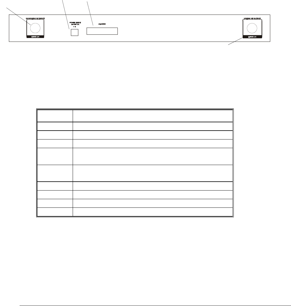
Table 2: Modular Base Unit Description
Number Description
1. Laser Output connection to MRC
2. Optical Diode Input from MRC
3. Power LED indicator
4. Modular Base Unit Laser operational LED
indicator
5. Modular Remote Cabinet Laser operational
LED indicator
6. Coax input from cellular headend
7. Power input connector
8. 25 pin Alarm connector
9. Coax output to cellular headend
6
9
7
8
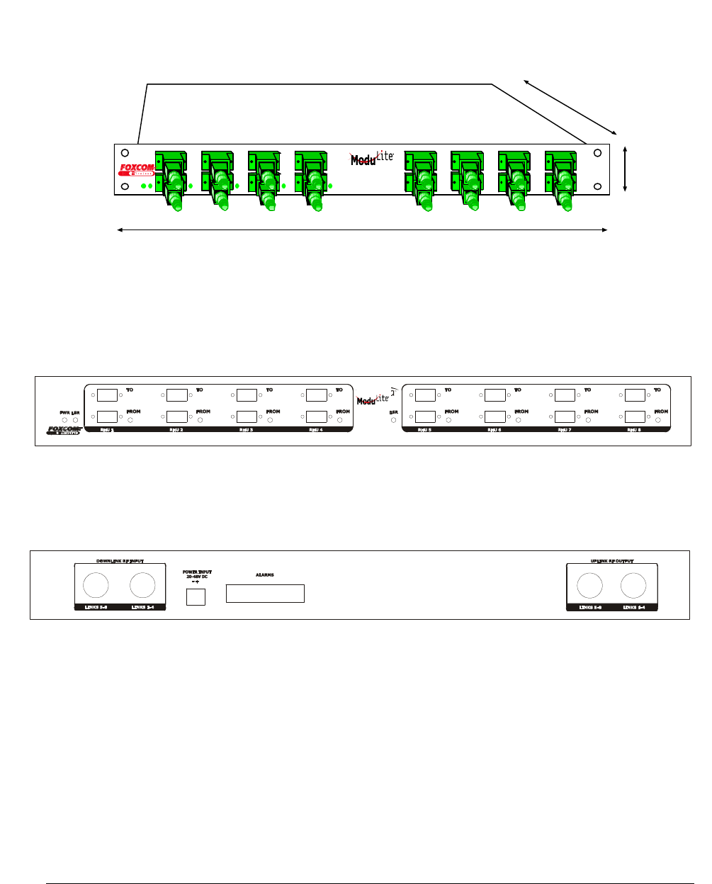
ModuLite Installation Guide INTRODUCTION TO THE MODULITE™
Foxcom Wireless Confidential and Proprietary Information
Document No. 43-93-005-05 y 14
2.3.2. Modular Base Unit- Eight Ports
”
U
”
Figure 6: Modular Base Unit 8 Ports
Figure 7: ModuLite™ Base 8 Unit Front Panels
Figure 8: ModuLite™ Base 8 Unit Back Panels
MBU
MB
ModuLite™ Installation Guide INTRODUCTION TO THE MODULITE™
Foxcom Wireless Confidential and Proprietary Information
Document No. 43-93-005-05 X1 15
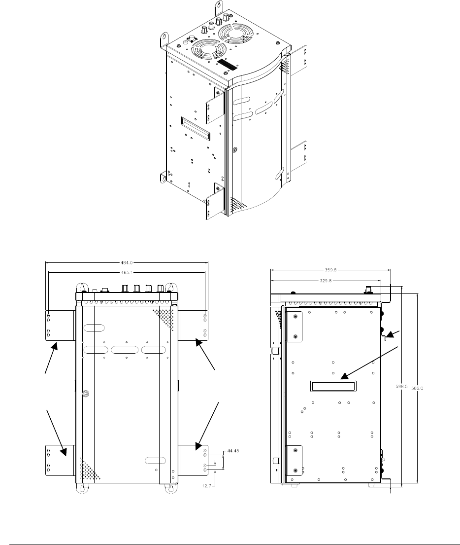
2.3.3. Modular Remote Cabinet (dimensions in millimeters)
2.3.3.1. Isometric View
2.3.3.2. Front and Side View
19´ brackets
19´ brackets
carrying cradle
mounting brackets
ModuLite Installation Guide INTRODUCTION TO THE MODULITE™
Foxcom Wireless Confidential and Proprietary Information
Document No. 43-93-005-05 y 16
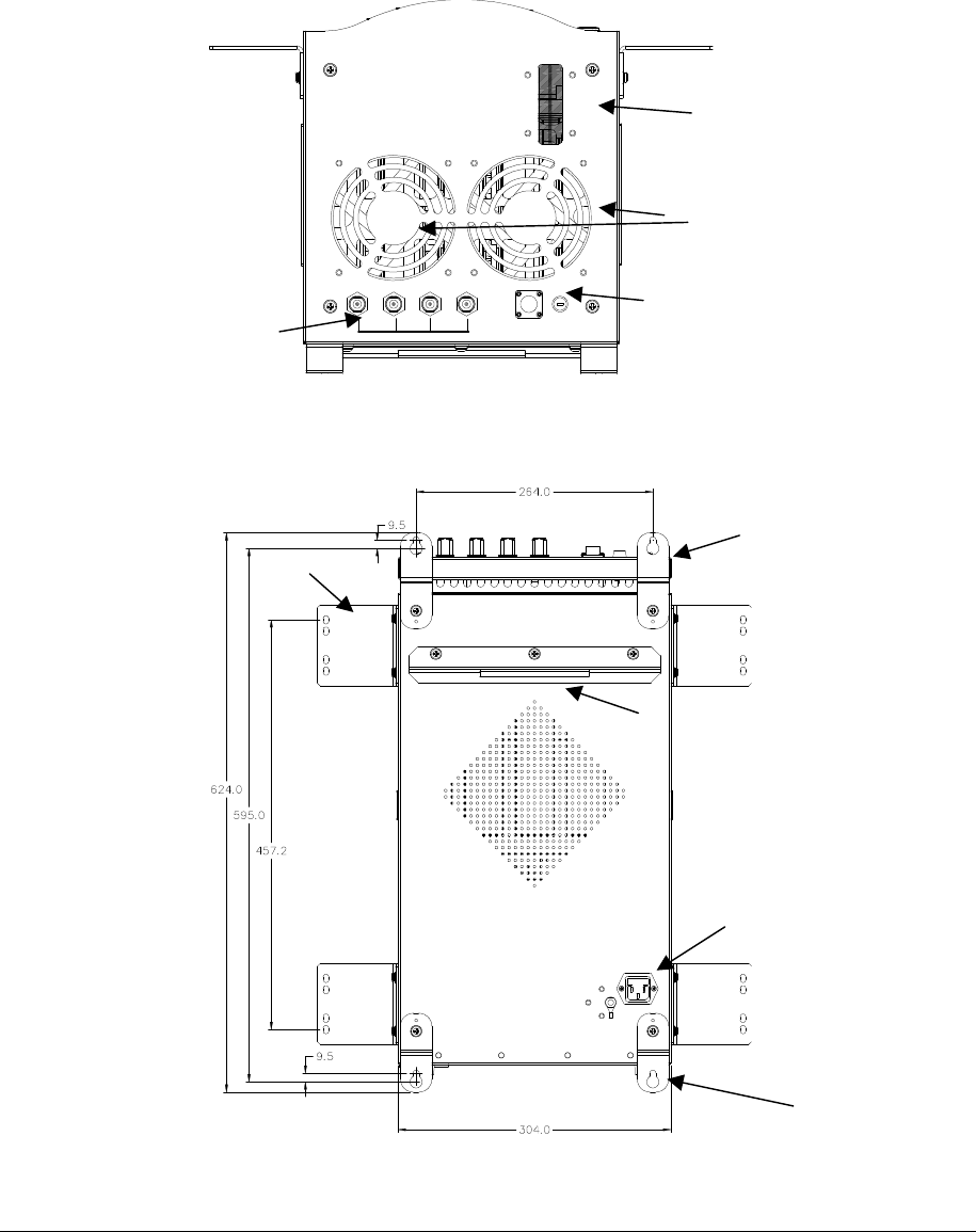
2.3.3.3. Top View
2.3.3.4. Back View
Note: Depending on the user’s preference, either wallmount or rackmount brackets will be
assembled.
Rackmount brackets
AC power input
Mounting bracket
Fiber optic cable
entrance
Antenna ports 1-
4
Fans
DC power input
Wallmount bracket
Wall mount bracket
ModuLite™ Installation Guide
Foxcom Wireless Confidential and Proprietary Information
Document No. 43-93-005-05 X1 17
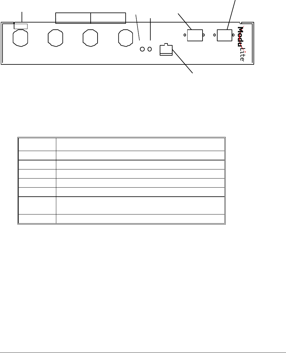
2.3.3.5. Module Front Panel
P
O
R
T
1
P
O
R
T
2
P
O
R
T
3
O
P
T
.
D
C
F
R
O
M
B
A
S
E
T
O
B
A
S
E
2
0
-
4
8
V
D
C
P
O
W
E
R
I
N
P
U
T
UL
DL/
RF IN OUT FILTERS
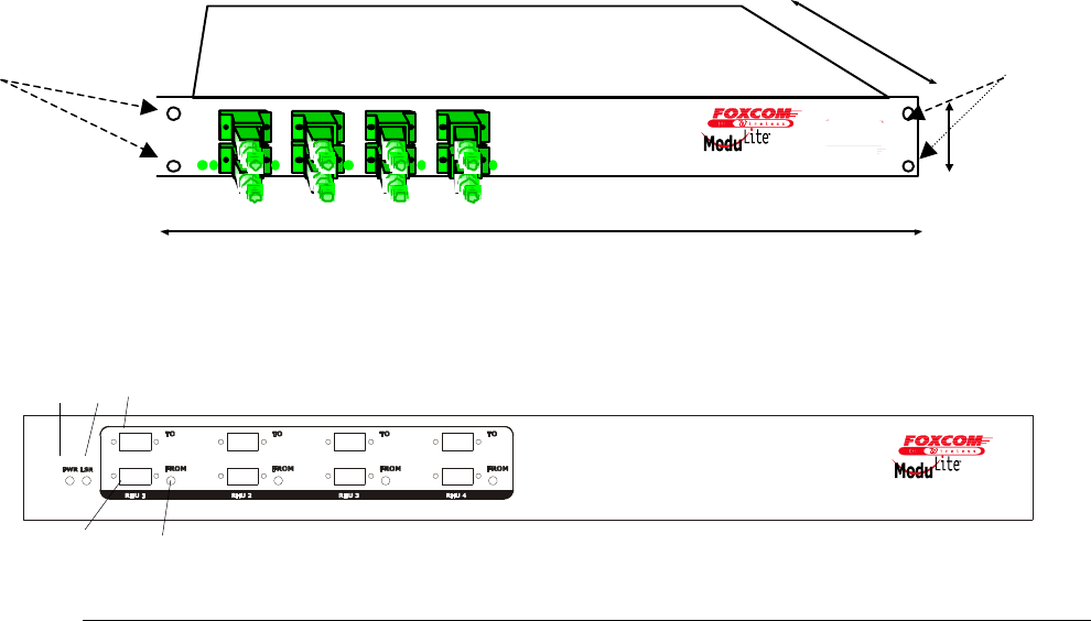
Figure 9: Modular Remote Cabinet Front Panel
Table 3: Modular Remote Cabinet Description
Number Description
1. RF In/Out
2. Filters
3. Optical LED for laser operation
4. DC power LED for power operation
5. DC power connector
6. Optical input connector from Modular Base
Unit
7. Laser output connector to Modular Base Unit
3
4
5
6
1
2
Modular Remote Unit
Cellular/PCS
7

ModuLite Installation Guide SETUP TESTS
Foxcom Wireless Confidential and Proprietary Information
Document No. 43-93-005-05 y 18
3. Setup Tests
This ModuLite™ product has been checked thoroughly before reaching the customer. Foxcom
Wireless attests to the suitability of this product for operation. Where the customer desires to
check the fitness of the product, the appropriate tests are listed on the following pages.
The following describes the equipment required for testing the system at setup.
Table 4: Required Equipment List
Required Setup Equipment Quantity
HP8753C Network Analyzer or equivalent
1
HP85046A S Parameter test set or equivalent 1
HP8594E Spectrum Analyzer or equivalent 1
Power supply /48 @ 5A 1
Signal generator HP8648B or equivalent 2
Amplifier Mini-circuit ZKL-2 or equivalent 1
Digital Multi-meter 1
RF Combiner Mini-Circuit ZAPD-21 or equivalent
with N connectors
1
High-grade 50-ohm phase matched cables:
N to N cables
N to SMA cables (in N remote type)
SMA to SMA cables (in SMA remote type)
4
2
3
Optical power meter (1310 nm) of EXFO model
number FOT-22A or equivalent 1
4 * Singlemode duplex fiber optic cable with SC/APC
connectors 3m
Calibration kit, including
Through (N-female to N-female)
Short (N-female)
50 ohm (N-female)

ModuLite™ Installation Guide SETUP TESTS
Foxcom Wireless Confidential and Proprietary Information
Document No. 43-93-005-05 X1 19
This section explains the following test procedures:
• Pre RF Test
• Flatness Test
• Gain/IP3 Test
• Uplink Network Test
In order to carry out the tests, the following connections need to be made. (The tests can be
performed on one service or several services simultaneously according to the implemented
application).
Connect the Modular Base Units corresponding with the service optical output to the Modular
Remote Cabinet’s optical input via fiber optic cable.
Connect power to all units being tested (20V-48V DC).
Use the relevant setup test for each Modular Base Unit to each Modular Remote Cabinet.
3.1. Pre RF Test
To carry out the Pre RF Test, the following procedure needs to be carried out.
1. Make sure all DC LED’s are lit on both units.
2. Measure Tx optical output power for all lasers.
3. Output power should be 1.8-3.7dBm (with optical power meter).
4. On the Modular Remote Cabinet, make sure that the optical LED’s is lit on all services.
5. On the Modular Base Units, make sure the Rx optical LED’s are lit.
ModuLite Installation Guide SETUP TESTS
Foxcom Wireless Confidential and Proprietary Information
Document No. 43-93-005-05 y 20
3.2. Flatness Test
To carry out the Flatness Test, the following procedure needs to be carried out.
1. Connect the Network Analyzer to the service designated Modular Base Unit. On the
Network Analyzer, the Modular Base Unit (according to the service) connects to port 2
2. On the Network Analyzer, the Modular Remote Cabinet connects to port 1 (see Figure 10).
3. After calibrating the network, set Network Analyzer to:
Measure
S21
Format
Log
Scale 1db/div
4. Apply with the required F1 and F2 should be according to Product Spec.
5. Measure the difference between the highest and the lowest signal point (which should be
as specified in the data sheet).
Figure 10: Network Analyzer Setup Test
ModuLite
Base Unit ModuLite
Remote Unit
Network Analyzer
Port 2 Port 1
RF In RF Out
Opt Out Opt In
20-48V 20-48V
ModuLite™ Installation Guide SETUP TESTS
Foxcom Wireless Confidential and Proprietary Information
Document No. 43-93-005-05 X1 21
3.3. Gain/IP3 Test
To carry out the Gain/IP3 Test, the following procedure needs to be carried out.
1. Set the 2 tone signal from the 2 signal generators. RF signals F1 and F2 should be
according to Product Spec.
2. Combine the signals with ZAPD-21 combiner or equivalent.
3. Connect the 2-tone signal to the input of the base (see Figure 11).
4. Set Spectrum Analyzer to:
Video BW 10khz
RBW 100khz
Attenuation 20db
Span 30Mhz
Center freq. Refer to Product Spec.
Ref level 10dbm
5. Connect the RF cable from the Modular Remote Cabinet output to the Spectrum
Analyzer.
6. Measure output Gain/IP3 from all test MRC’s downlink outputs.
7. IP3 is determined by:
IP3= power tone + (power tone – power IM3)/2.
ModuLite
Remote Cabinet
ModuLite
Base Unit
RF Combiner
SG1
Spectrum
Analyzer
SG2 20-48V 20-48V
RF
In Opt
Out Opt
In RF
Out
DC
In
DC
In
ModuLite Installation Guide SETUP TESTS
Foxcom Wireless Confidential and Proprietary Information
Document No. 43-93-005-05 y 22
Figure 11: Spectrum Analyzer Setup Test
3.4. Uplink Network Test
To carry out the Noise Floor test, the following procedure needs to be carried out.
1. Connect the Spectrum Analyzer to the designated Modular Base Unit uplink port.
Connect 50ohm terminators to the MRC ports, and to all Modular Base Unit uplink ports
except for the tested port (see Figure 12).
2. Extra amplification (25db) is applied between Modular Base Unit and Spectrum
Analyzer in order to measure the noise floor.
3. Set Spectrum Analyzer to:
Video BW 300hz
RBW 1khz
Attenuation 0db
Span 0hz
Center freq. Refer to Product Spec.
Ref level -50dbm
Marker noise ON
4. The noise figure is formulated as: -174 + Gsystem + noise floor
(On the MRC, all unused ports must be terminated with 50ohm load.)
Figure 12: Uplink Network Test
ModuLite
Remote Cabinet
ModuLite
Base Unit
Spectrum
Analyzer
20-48V
20-48V
RF In
Opt
Out Opt
In
RF
Out
DC
In
DC
In
Uplink
1
2
AMP
RF
Out

ModuLite™ Installation Guide INSTALLATION
Foxcom Wireless Confidential and Proprietary Information
Document No. 43-93-005-05 X1 23
4. Installation
The following sections describe the ModuLiteTM installation.
• General Installation.
• Fiber Installation.
• Hi Rise Installation.
• Horizontal Layout Installation.
4.1. General Installation
The ModuLite™ components need to be set up, followed by performance verification before
installing the system. Foxcom Wireless suggests that a 19” rack-mountable Splice Tray be used at
the Modular Base Unit to facilitate optical fiber splicing. In the rack, the Splice Tray is mounted
above or below the Modular Base Unit (depending on direction of the incoming cables).
The MBU and MRC units should be installed in a communication room that provides access
to authorized personnel only. The units are maintenance free. In the event of failure, only
authorized personnel should handle the units.
Set up procedures for the Modular Base Unit (MBU) and Modular Remote Cabinets (MRC) are for
the following installations:
• High-rise installations.
• Horizontal layout installation.
For both installations, setting up the Modular Base Unit and Modular Remote Cabinets consists of
the following steps:
1. Determine antenna placement by system engineer: When an area needs RF cellular
augmentation, a RF engineer needs to determine the type and the location for each antenna. The RF
engineer should consider all relevant RF parameters (RF propagation models, isolation between
antennas in accordance with the appropriate standard, and environmental conditions) as well as
landlord limitations.
2. Determine the amount of antennas required. This number, in turn, determines the number of
Modular Remote Cabinets to be used. The number of Modular Remote Cabinets has a direct
influence on the type and the number of fibers to be installed.
3. Pull fiber optic cable and copper cables through building. Install fiber optic cable according to
the optic design (see Figure 17) Prepare 10% to 15% more fibers than are actually required. In order
to supply D.C power to the Modular Remote Cabinets remotely, copper cables need to be installed
in parallel to the fiber optic cable (see Figure 17).

ModuLite Installation Guide INSTALLATION
Foxcom Wireless Confidential and Proprietary Information
Document No. 43-93-005-05 y 24
4. Install Modular Base Unit in 19” rack. The number of Modular Base Units depends on the
number of Modular Remote Cabinets. Each Modular Base Unit is installed with four screws on the
front panel (two on each side) connecting to the 19” rack.
5. Install patch panel/splice tray cabinet with SC/APC adaptors in a 19” rack or wallmount
near Modular Base Units. All fibers are installed in the patch panel, in which the backside is the
fiber optic cable/cables coming from the remote side, and in the front side are SC/APC adaptors and
SC/APC jumpers to the Modular Base Units.
6. The fiber contractor splices fiber cable to the SC/APC connectorized pigtails. In the
communication room the fiber contractor splices/connects the fiber optic cable/cables coming from
the remote end with SC/APC connectorized pigtails inside the patch panel cabinet. The pigtails
connector will be connected to the SC/APC adaptors on the patch panel (from the inside).
7. Connect SC/APC jumpers between SC/APC adaptors on the patch panel to the Modular
Base Units. For every optic link (MBU--MRC) there are two fibers – one uplink and one downlink
per service.
8. Connect BTS/RBS to Modular Base Units via ½” coax cable RG223 or similar with 50Ω
impedance according the RF design (see paragraph optical and RF connections).
9. In the remote end connect pigtail/jumpers fibers from the splice box to each MRC. One splice
box can support several MRC’s according to the optical design (normally three MRC’s).
10. Connect antennas to Modular Remote Cabinet via ½” or 3/8” or similar coax cable with 50Ω
impedance and N-type male to male.
11. Connect power supply to Modular Base Unit and Modular Remote Cabinet (refer to power
planning). Each Modular Base Unit will be connected with D.C. cables (+, -) directly to the planned
power supply. The MRC’s will be connected to the D.C. cables through D.C. clamping coming
from the communication room.
4.2. Environmental Data
Maximum ambient operating temperature: 50° C
Maximum ambient temperature in a rack: 50° C

ModuLite™ Installation Guide INSTALLATION
Foxcom Wireless Confidential and Proprietary Information
Document No. 43-93-005-05 X1 25
4.3. Configuration Restrictions
UPLINK DOWNLINK
Figure 13: PCS Frequency Allocation
The following configuration restrictions apply: (Please refer to Figure 13 above.)
• PCS operator operating on block A and the Paging operator must not reside on the same MRU.
• PCS operator operating on block B and the SMR operator must not reside on the same MRU.
• PCS operator operating on block A and B and the SMR and Paging operators must not reside
on the same MRU.
• The PCS band is divided into six blocks. Blocks A, B, and C are 15 Mhz and blocks D, E, and F
are 5 Mhz. Only two adjacent blocks can be used on the same MRU. The adjacent blocks are:
A and D, B and E, and F and C.
4.4. Environmental Data
Maximum ambient operating temperature: 45° C
Maximum ambient temperature in a rack: 45° C
A
15
MHz
D
5
M
Hz
B
15
MHz
E
5
M
Hz
F
5
M
Hz
C
15
MHz
C
15
MHz
F
5
M
Hz
E
5
M
Hz
B
15
MHz
D
5
M
Hz
A
15
MHz
1850
1870
1890
1910
1930
1950
1970
1990
ModuLite Installation Guide INSTALLATION
Foxcom Wireless Confidential and Proprietary Information
Document No. 43-93-005-05 y 26
4.5. Protective Earthing
See Figure 14 below, which describes how to connect the ground to the MRC. Connect the GND wire to
the GND of the rack (for a rackmount) or to the GND of the building (for a wallmount).
SIDE VIEW
TOOTH WASHER
FLAT WASHER
HOUSING WALL
WING NUT
GND STANDOFF
TERMINAL LUG
GND WIRE
16 AWG
Figure 14: ModuLite™ GND Standoff Assembly Sequence
4.6. Wallmount Installation
(The following instructions apply to an installation on a concrete wall. For any other type of wall,
contact the manufacturer.)
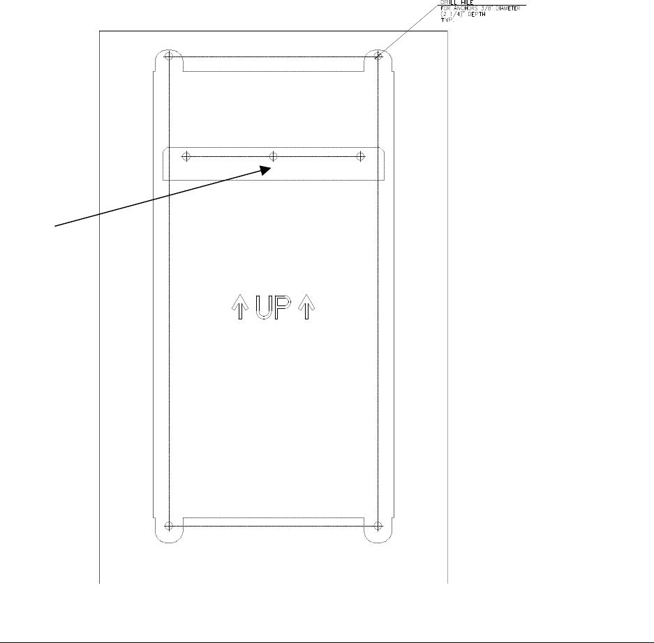
Please refer to Figure 15 and to Figure 16.
1. Attach the alignment template to the wall.
2. Using the template as a guide, drill seven holes for concrete anchors. Insert seven concrete
anchors (McMaster-Carr catalogue number 92403A200, or equivalent). The middle holes
are designated for the mounting bracket. The other four holes are for the wallmount bracket.
3. Carefully and thoroughly fasten the anchors to the wall.
ModuLite™ Installation Guide INSTALLATION
Foxcom Wireless Confidential and Proprietary Information
Document No. 43-93-005-05 X1 27
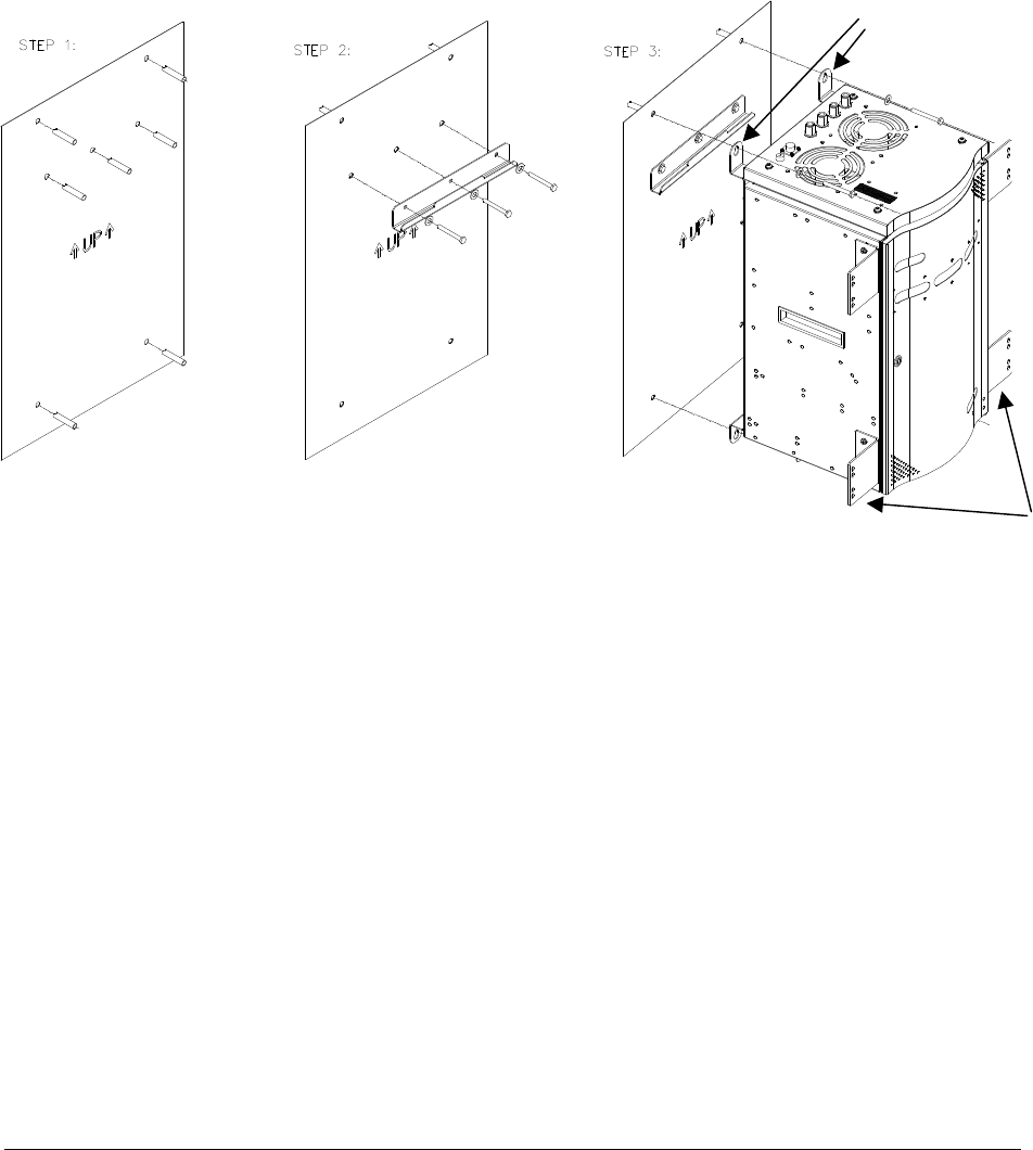
4. Remove the three screws from the anchors in the holes designated in Figure 15 for the
mounting bracket. In the other four anchors loosen but do not remove the screws.
5. Using the screws removed from the mounting bracket anchors, attach the mounting bracket
through the three holes.
6. Insert the mounting bracket attached to the rear of the MRC into the mounting bracket
attached to the wall while maneuvering the four wallmount brackets into the four screws
previously loosened but not removed. Do not tighten these four screws so that the MRC
can be removed without requiring any tools.
Figure 15: Wallmount Template
Three holes
for
mounting
bracket
ModuLite Installation Guide INSTALLATION
Foxcom Wireless Confidential and Proprietary Information
Document No. 43-93-005-05 y 28
Figure 16: Procedure for Mounting on a Wall
4.7. Rackmount Installation
For a rackmount installation, attach the MRC to the rack using the rackmount brackets (see Figure
16). The MRC should be hung in the lower section of the rack. Use 12 mm M6 screws.
The MRC requires a clearance of 10 cm above the unit. If a heating source is installed beneath the
MRC, a buffer must be placed between the MRC and the surface.
For MBU rackmount installation, see Figure 3. Use 12 mm M6 screws.
Wallmount brackets
–
not necessary for
rackmount
installation
Rackmount brackets–
not necessary for
wallmount installation
ModuLite™ Installation Guide INSTALLATION
Foxcom Wireless Confidential and Proprietary Information
Document No. 43-93-005-05 X1 29
4.8. Fiber Installation
The following procedure describes the process for setting up fiber optic cable for the system (see
Figure 17).
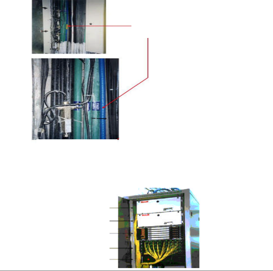
1. Pull fiber optic cable and DC cable through building structure
2. Install splice tray (when used) in 19” rack near Modular Base Unit.
Comparison: Coax
complex vs. Fiber
solution
Patch Panels
Splice trays
Base 4 Units
Power

ModuLite Installation Guide INSTALLATION
Foxcom Wireless Confidential and Proprietary Information
Document No. 43-93-005-05 y 30
3. Near Modular Base Unit, install patch panel cabinet (SC/APC adaptors) for fiber optic
cable connections.
4. Connect (3/125/900) pigtail with SC/APC connectors between splice tray and patch panel
cabinet.
5. Connect (3/125/3000) SC/APC jumpers between the corresponding Modular Base Unit and
patch panel.
6. Install splice box near MRC (refer to optic planning).
7. Connect fiber optic cable to splice box and (3/125/3000) pigtails to MRC.
ModuLite™ Installation Guide INSTALLATION
Foxcom Wireless Confidential and Proprietary Information
Document No. 43-93-005-05 X1 31
Figure 17: Example - ModuLiteTM Installation (fiber and coax)
∼
Floor 9
Floor 2
MRC
2-8 Fibers
Fiber Optic
Cable
Floor 7
2-8 Fibers
Patch panel
Splice tray
MBU
PigTail
Jumpers
Splice
box
MRC
MRC
MRC
19" Rack
Power Supply
DC
Cable
Splice
box
Floor 32
ModuLite Installation Guide INSTALLATION
Foxcom Wireless Confidential and Proprietary Information
Document No. 43-93-005-05 y 32
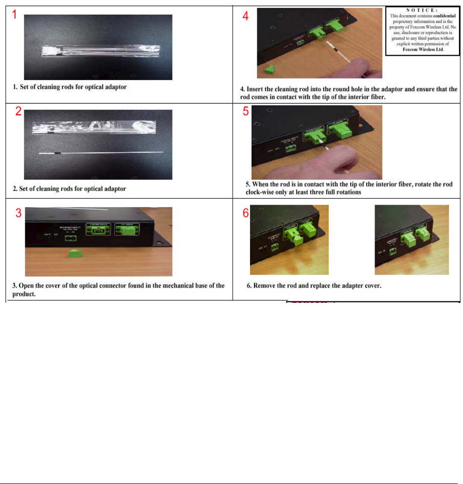
4.8.1. Fiber Optic Cable
Before connecting the cable, clean the inside adaptor of the ModuLite™ according to the following
instructions:
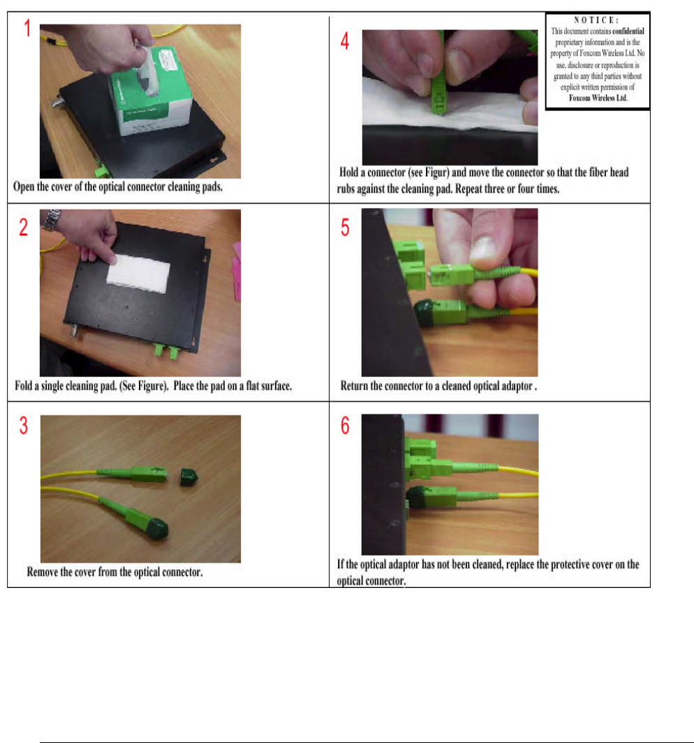
ModuLite™ Installation Guide INSTALLATION
Foxcom Wireless Confidential and Proprietary Information
Document No. 43-93-005-05 X1 33
Clean the connectors as follows:
ModuLite Installation Guide INSTALLATION
Foxcom Wireless Confidential and Proprietary Information
Document No. 43-93-005-05 y 34
To connect the cable:
• Line Up the Polarity Key.
• Insert the connector.

ModuLite™ Installation Guide INSTALLATION
Foxcom Wireless Confidential and Proprietary Information
Document No. 43-93-005-05 X1 35
4.8.2. ModuLite™ Installation Parts List
The following parts are needed for setting up the ModuLiteTM Base and Modular Remote
Cabinets. A fiber contractor handles cable splicing in order to connect the units. The fiber
contractor needs to use the parts list from Table 5 to arrange all equipment necessary for setting up
and installing the ModuLiteTM.
Table 5: ModuLiteTM Installation Parts List
The following tables refer to a full configuration 32 floor building:
Equipment Description Quantity Comment
Coax cable (per 1m) according to
the technology (7-8dB loss for
100m in 1000MHz)
Connect MRC to
antenna. As needed
Antenna As planned
Optical cable (8*9) 72 fibers –
singlemode fiber Optic cable for short
distance & protected
environments (tight
buffer type).
Total=500m
Patch panel 72 cabinet with
SC/APC adaptors. Connect jumpers to base
and pigtails to splice tray. 2
Splice box Connects optic cable
from Cabinet and pigtails
to MRC.
11 1 per 3
floors
Splice tray Tray-1*50 connects cable
optic and pigtails near
Modular Base Unit.
4 In some
cases in
patch panel
9/125/3000 3m optical jumpers
with SC/APC connector
(simplex).
Connect patch panel to
MBU. 256
9/125/900 5m Pigtail with
SC/APC connectors (B)
Connect patch panel and
splice tray. 344
9/125/3000 15m Pigtail with
SC/APC connectors (R)
Connect patch panel and
splice tray. 168
Electricity cables (per 1m) Delivers power to units. According
to length.
Electricity ducts (per 1m) Ducts for moving cables
though building. According
to length. If needed
Coax connectors n-type Cable connectors As needed

ModuLite Installation Guide INSTALLATION
Foxcom Wireless Confidential and Proprietary Information
Document No. 43-93-005-05 y 36
Table 6: ModuLite™ Installation Labor List
Labor Description Quantity Comment
Installing splice box + splicing
fibers Installing the box and
opening fibers at MRC. 11
Installing patch panel cabinet +
splicing fibers Installation of the box and
opening fibers at MBU. 256
Installing Foxcom Wireless
equipment Installing Modular Base
Units and MRC’s. 36
Installing optic cable
(per 1m) Pull and install optic cable
through building.
Installing coax cable antennas Install cable antennas on
each floor
Installing electricity ducts (per 1m) Install cables through
ducts in building. If needed
Installing electricity cables Install cables through
ducts in building.
System checking and report. Trouble shooting and walk
test.
ModuLite™ Installation Guide INSTALLATION
Foxcom Wireless Confidential and Proprietary Information
Document No. 43-93-005-05 X1 37
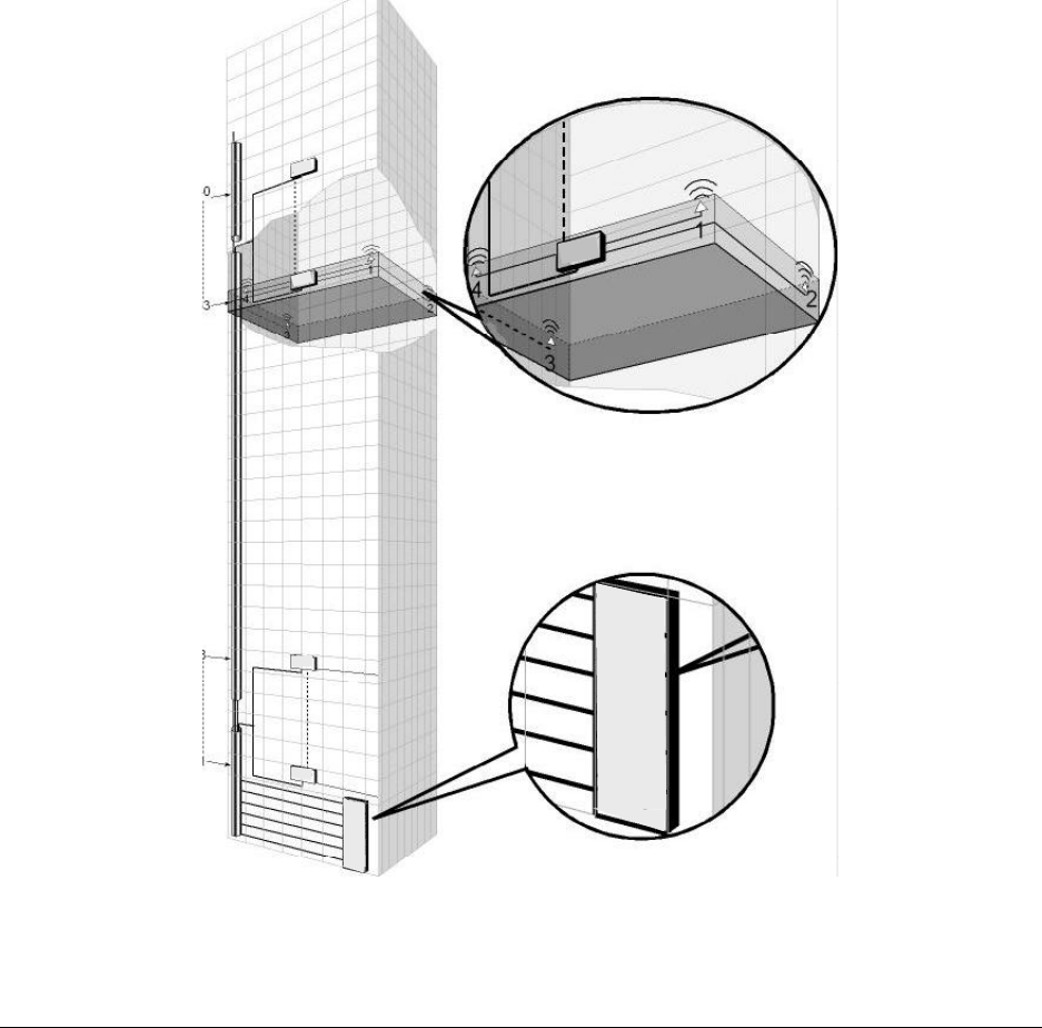
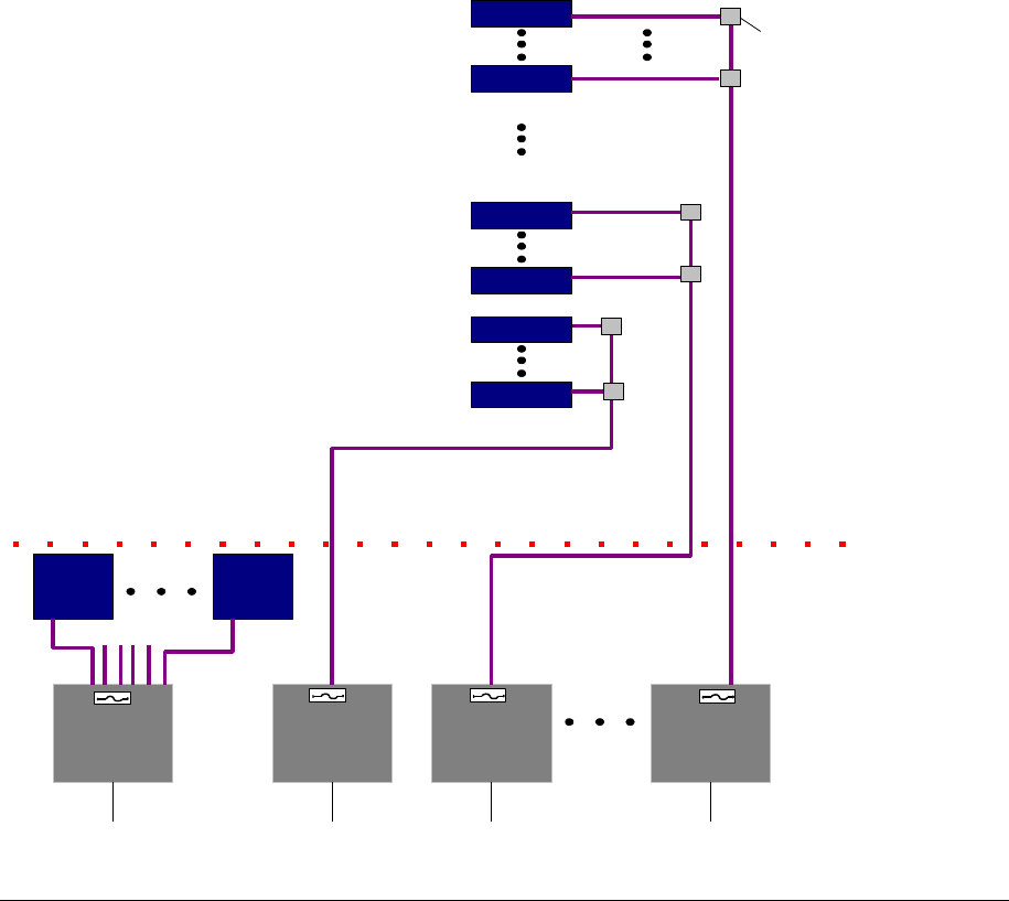
4.9. High Rise Installation
In a high-rise installation, all MBU’s are placed in the same location. The MBU’s are connected to
the BTS/RBS (see BTS/RBS connection – page 44). An MRC can be located on every floor
according to the RF design. The fiber optic cable runs from the MBU to every floor and terminates
at the splice box located on every three floors of the building. Normally, every splice box connects
three MBU’s. From the splice box, the fiber optic jumpers connect to the associated MRC. From
each MRC, a coax cable delivers the signal to the antenna.
MRC
MBU’s
MBU¶s
Figure 18: High Rise Installation
ModuLite Installation Guide INSTALLATION
Foxcom Wireless Confidential and Proprietary Information
Document No. 43-93-005-05 y 38
4.10. Horizontal Layout Installation
In a horizontal layout installation, one fiber optic cable connects the MBU to every installed MRC.
The fiber optic cable terminates at a splice box located near the MRC and from the splice box
connects to the associated MRC.
M
BU
A
C
G
H
E
CE
L
L
S
I
T
EB
A
S
E
U
N
I
T
F
I
D
B
M
R
RC
R
M
R
M
C
C
EL
L
SIT
E
BU
A
B
C
D
E
F
G
I
H
M
R
M
C
MRC
Figure 19: Horizontal Layout Installation
4.11. Wireless LAN Installation
Two products are available in the Modulite 800 Series:
Modulite 810 1 AP
Modulite 840 1-4 Ap’s
Figure 20 shows the 810 module in the MRC:
ModuLite™ Installation Guide INSTALLATION
Foxcom Wireless Confidential and Proprietary Information
Document No. 43-93-005-05 X1 39
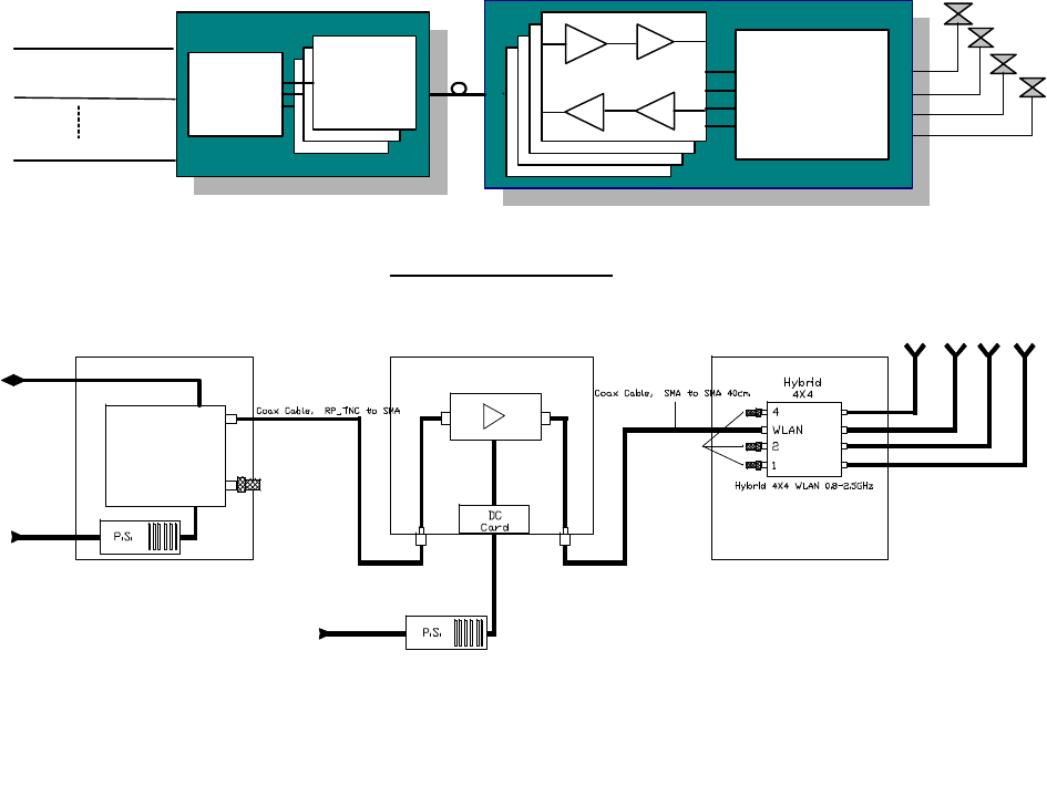
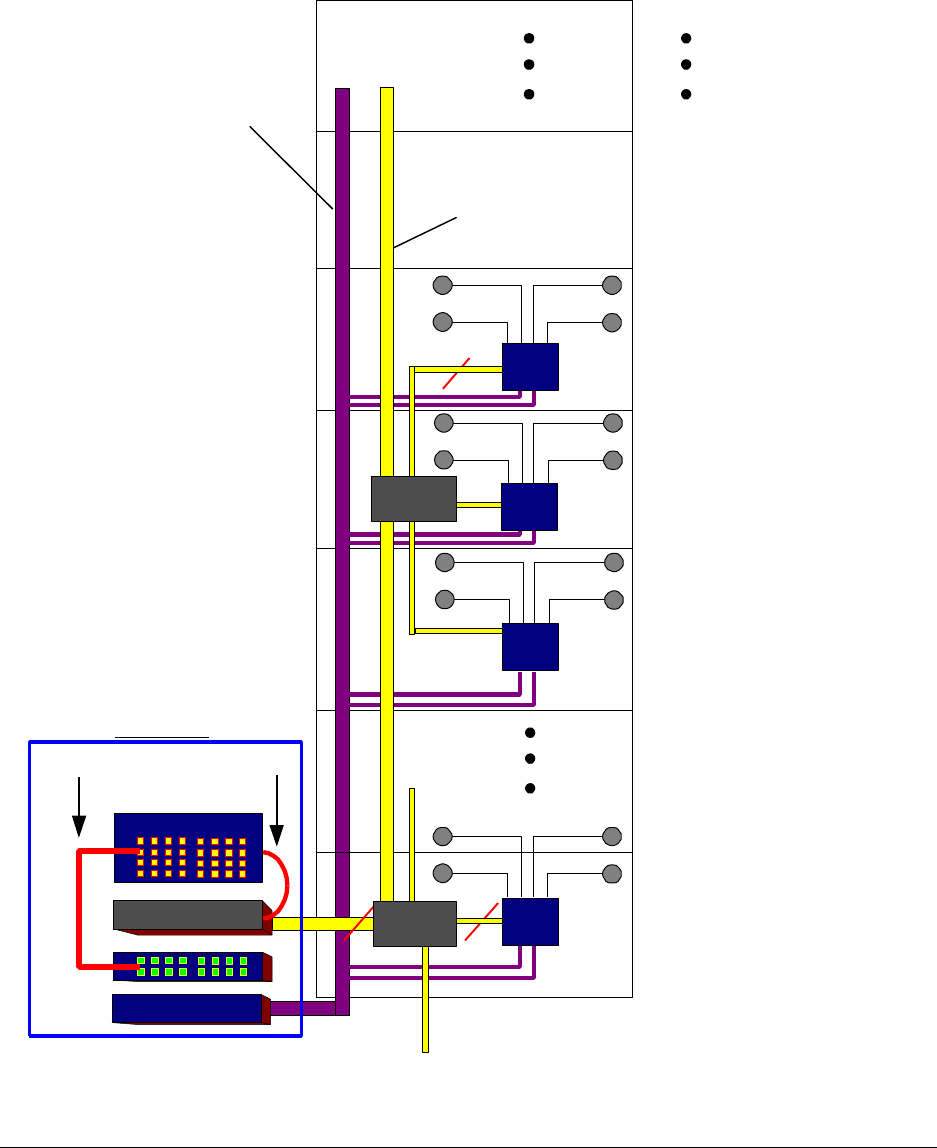
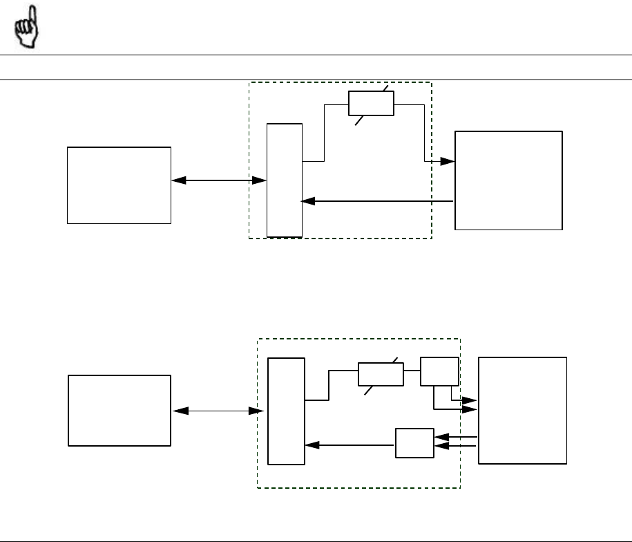
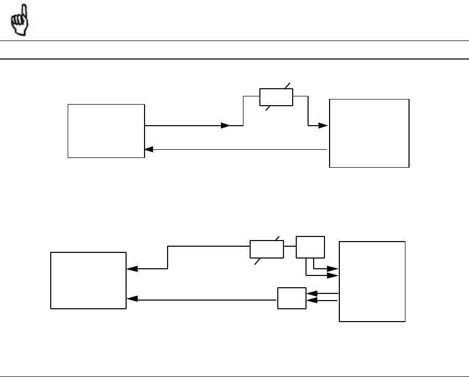
4.11.1. System Configuration with Modulite 810
depicts the system configuration for Wireless LAN as part of the ModuLite™ product. The
Auxiliary Modle including power amplifier and power supply DC/DC that resides in the MRC
cabinet. The access point module is connected via a power amplifier that is used to increase the
coverage area of the access point. The power amplifier is connected to the 4*4 hybrid combiner
that sums the cellular services signals together with the Wireless LAN signal and then sends the
signal to four antennas. See Figure 22 for connector points from the Auxiliary Modle.
Figure 21: 802.11b Configuration
Figure 20: ModuLite™ MRC Interior with Auxiliary Modle
Auxiliary Modle
ModuLite Installation Guide INSTALLATION
Foxcom Wireless Confidential and Proprietary Information
Document No. 43-93-005-05 y 40
Figure 22: Connector Points on the Auxiliary Modle
Power Output: Can be used
to power the WizLan
“RF in” Connection
to the Access Point
“RF out” Connection
to the
4*4 hybrid
ModuLite™ Installation Guide INSTALLATION
Foxcom Wireless Confidential and Proprietary Information
Document No. 43-93-005-05 X1 41
4.11.2. System configuration with 840
The Modulite 840 supports 1- 4 AP¶s and is used when there is a request to support increased
capacity in the same location. The following drawing describes the system configuration.
Figure 23 - system configuration with Modulite 840
The MRC antenna ports are connected to the 840 Cellular ports and are combined with the AP WLAN
signal of the AP and the Modulite 810. The Modulite 810 is an optional module. The combined signal
WLAN (from the AP’s and the Modulite 810) and the Cellular/PCS signal from the MRC are combined
together and distributed to 4 antennas.
The following table describes the configuration when a different number 1-4 AP are connected to the
840.
MRC Modulite
AP
cisco Modulite
optional
AP
cisco Modulite
optional
AP
cisco Modulite
optional
AP
cisco Modulite
optional
ANT
ANT
ANT
ANT
Antenna
Antenna
Antenna
Antenna

ModuLite Installation Guide INSTALLATION
Foxcom Wireless Confidential and Proprietary Information
Document No. 43-93-005-05 y 42
# of Access Points Access point designator Connected to Antenna
1 AP 1 1,2,3,4
2 AP1 1,2
AP2 3,4
3 AP1 1,2
AP2 3
AP3 4
4 AP1 1
AP2 2
AP3 3
AP4 4
Indoor Wide band Antennas
Combining the Cellular and the WLAN services requires using wide band antennas. Attached are the
recommended antennas tested and approved by Foxcom Wireless.
Vendor Catalog number Gain [dBi]
Mars Antennas MA-CM36-15 2 low band
3-4 high band
5 WLAN 802.11b
Celwave A08818DC00-28T0 2.1
Antenna ASP-3561 2
ModuLite™ Installation Guide INSTALLATION
Foxcom Wireless Confidential and Proprietary Information
Document No. 43-93-005-05 X1 43
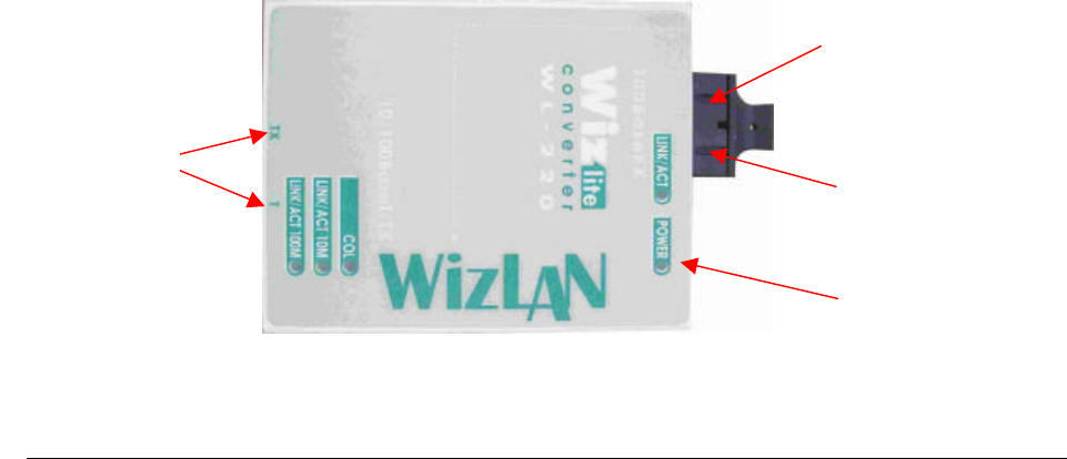
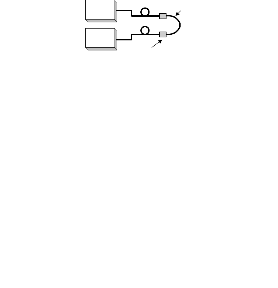
4.11.3. Connecting to the Ethernet Line
The connection to the Ethernet line can be accomplished in two different ways:
1. Via local connection, or
2. Concentrated remote location.
The local connection can be made by connecting each MRC located at each floor (in a typical
configuration) to the nearest Ethernet line on the same floor. The RJ45 should be connected by cable
to the nearest Ethernet line. The advantage in this configuration is that one can save on fiber
installation that runs from each floor to a central location to be connected to the Ethernet.
The remote connection can be accomplished by using two WizLans (see next page). These two
components are used to convert Ethernet to a fiber optic signal and vice versa.
The Ethernet signal will be converted to fiber optic signal in the amplifier module and sent via the
fiber optic cables to the second converter located next to the remote Ethernet connection (located in
the communication room of the building).
The following steps should be used to connecting the access point to the Ethernet:
1. The Ethernet to fiber optic converter can be mounted on the wall. Use two screws to
connect the WizLAN (Ethernet to fiber optic converted) to the wall.
2. Connect the fiber optic cables to the WizLAN.
3. Connect the WizLAN to the power adapter. (AC to 5 VDC power supply.)
4. Connect the Ethernet link to the WizLAN.
Figure 24: WizLAN Converter
Tx
P
ower
To Ethernet
Rx

ModuLite Installation Guide OPTICAL AND RF CONNECTIONS
Foxcom Wireless Confidential and Proprietary Information
Document No. 43-93-005-05 y 44
5. Optical and RF Connections
The following sections describe the ModuLite™ optical and RF connections.
• MBU- Modular Base Unit
• MRC- Modular Remote Cabinet
5.1. Modular Base Unit (MBU)
The MBU can be considered as main Hub connected to each specific service.
There are two set-up options for the MBU:
• BTS/RBS with one port
• BTS/RBS with two ports
ModuLite™ Installation Guide OPTICAL AND RF CONNECTIONS
Foxcom Wireless Confidential and Proprietary Information
Document No. 43-93-005-05 X1 45
5.1.1. BTS/RBS with one port
1. BTS/RBS must be connected to a duplexer (standard), via 50Ω (RG223) coax cable.
2. The downlink port is connected through attenuators to the designated input of the Modular
Base Unit, according to the service and required input power.
3. When more than one ModuLite™ Base 4 Unit is used to the same service, splitters are
required to connect to the other Modular Base Unit inputs from the same service.
4. The uplink from the Modular Base Unit will only combine the required ports and connected to
the duplexer uplink port via 50Ω (RF 223) coax cable.
5. Connect the fiber optic cables from the Modular Base Unit to the MRC’s through the patch
panel cabinet.
6. Connect the power supply to the units locally or remote, according to power design planning.
Note
All Coax cables are male-to-male 50Ω.
Interface Box
Figure 25: Example: One port BTS/RBS connected to 1 MBU 4 ports
Interface Box
BTS
2way
ModuLite
Base 8 Unit
Duplexer
Attenuator
2way
BTS
ModuLite
Base 4 Unit
Duplexer
Attenuator
ModuLite Installation Guide OPTICAL AND RF CONNECTIONS
Foxcom Wireless Confidential and Proprietary Information
Document No. 43-93-005-05 y 46
Figure 26: Example - One port BTS/RBS connected to 1 MBU 8 ports
5.1.2. BTS/RBS with two ports
1. The BTS/RBS downlink port should be connected via a 50Ω (RG223) coax cable to the
corresponding Modular Base Unit input via an attenuator.
2. The downlink coax cable coming from the BTS/RBS should be split using splitters to all
Modular Base Unit input ports (split according to need).
3. The input power for each Modular Base Unit should be calculated to meet the product
specifications according to each service.
4. For the uplink, only necessary ports will be combined and connected to the BTS/RBS
uplink port with suitable combiner. All unused ports should be terminated with 50Ω load.
Note
All cables are coax jumpers (male to male 50Ω ).
Interface Box
Figure 27: Example - Two port BTS/RBS connected to 1 MBU 4 ports
Interface Box
Attenuator
ModuLite
Base 4 Unit
BTS
BTS
2way
ModuLite
Base 8 Unit
Attenuator
2way

ModuLite™ Installation Guide OPTICAL AND RF CONNECTIONS
Foxcom Wireless Confidential and Proprietary Information
Document No. 43-93-005-05 X1 47
Figure 28: Example- Two port BTS/RBS connected to 1MBU 8 ports
5.2. Modular Remote Cabinet (MRC)
1. For the downlink, connect the fiber optic cable pigtails from splice box coming from the
Modular Base Unit port to the corresponding Modular Remote Cabinet port (according to
the service).
2. Connect the Modular Remote Cabinet to antennas according to the RF engineers design
using ½” or 3/8” coax cable. (Up to four antennas per MRC).
3. For the uplink, connect the fiber optic cable pigtails from splice box from the Modular
Remote Cabinet to the uplink port that connects to the Modular Base Unit corresponding to
the same service.
4. Connect the power supply to each MRC according to power design planning.

ModuLite Installation Guide ALARM MONITORING
Foxcom Wireless Confidential and Proprietary Information
Document No. 43-93-005-05 y 48
6. Alarm Monitoring
The Modular Base Unit has a 25 pin D-type connector that is connected to 4 dry contact relays
(MB4U). Each of the relays indicates the status of the link between the MBU and one of the
MRC’s. This capability provides the status of the optical communications for each service. The
relay connections on the 25pin D-type connector can be connected directly to the BTS alarm
relays and can be monitored from the remote end.
In order to transmit the ModuLite™ system as a “major alarm”, all dry contact pins need to be
connected in a serial (cascade) formation, for Normally Closed alarm. All dry contacts need to be
connected in parallel formation, for Normally Open alarm.
Note
For further information contact Foxcom Wireless
Table 7: 25 Pin Alarm Pinouts
Pin Type of Alarm Port
1 Dry Contact 4 1
2 Dry Contact 4 2
3 Open Collector 4
4 Dry Contact 1 1
5 Dry Contact 1 2
6 Open Collector 1
7 Dry Contact 2 1
8 Dry Contact 2 2
9 Open Collector 2
10 Dry Contact 3 1
11 Dry Contact 3 2
12 Open Collector 3
13 Dry Contact 8 1
14 Dry Contact 8 2
15 Open Collector 8
16 Dry Contact 5 1
17 Dry Contact 5 2
18 Open Collector 5
19 Dry Contact 6 1
20 Dry Contact 6 2
21 Open Collector 6
22 Dry Contact 7 1
23 Dry Contact 7 2
24 Open Collector 7
25 - -
ModuLite™ Installation Guide POWER SUPPLY FOR MODULITE™
Foxcom Wireless Confidential and Proprietary Information
Document No. 43-93-005-05 X1 49
7. Power Supply for ModuLite™
The power supplies to drive the ModuLite™ can be purchased from Foxcom Wireless. The
power supplies will be installed into a rack or mounted on a wall and will provide power for both
the Modular Base Units and Modular Remote Cabinets.
The example below (Figure 29) depicts a ModuLite™ system consisting of CDMA800,
GSM1800, and GSM Dual Band, with 500W/ 48VDC AC/DC converters providing power for a
total of 1.5A per unit.
Between the AC/DC converters and the units, a circuit breaker (maximum 10A) must be
installed, either in the AC/DC converter or nearby.
Figure 29: Example - DC Power Supply in High Rise Installation
AC/DC
2AC/DC
3AC/DC
6
MRC 32
AC/DC
1
MBU 1 MBU 4
48VDC 48VDC 48VDC 48VDC
BASE
STATION
2.5mm
2
110/220
VAC 110/220
VAC 110/220
VAC 110/220
VAC
MRC 26
MRC 13
MRC 7
MRC 6
MRC 1
16mm2
2.5mm
2
2.5mm
2
16mm2
2.5mm
2
16mm
2
Clamping
Connector
Fuse Fuse Fuse Fuse10A
10A
10A 10A

ModuLite Installation Guide POWER SUPPLY FOR MODULITE™
Foxcom Wireless Confidential and Proprietary Information
Document No. 43-93-005-05 y 50
The power supply that drives the ModuLite™ system can be purchased from Foxcom Wireless.
Four power supply options are available.
7.1. Option One (Remote Power)
In this option the MBU is connected to the power supply via electrical cables. In order to power
the MRC from the power supply, two copper electrical wires running through the building
(separately from the fiber optic cables) supply power to each MRC in parallel. For this
configuration, electrical power calculations need to be made. This option is shown in Figure 29.
7.2. Option Two (Local Powering)
In this option the power supply type is a standalone configuration. Power for both the MBU and
MRC’s will be supplied separately. In this configuration each unit will be co-located with a
power supply. This will not require running long electrical cables.
7.3. Option Three (Built-In Powering)
In this option the power supply type for the MRC’s is A.C. Each MRC will come with a built-in
power supply source. To power the MBU’s, local D.C. power will be used. This will not require
running long electrical cables.
Table 8: Power Supply Options
Note
For further information refer to Foxcom Wireless Power Supply manual and Power Supply
Planning Rules.
Materials Model
Local power supply LPS-150-N-2A
Remote power supply (no redundancy) RPS-200-N-48
Remote power supply (fully redundant) RPS-150-R-48
Remote power supply (fully redundant) RPS-500-R-48
Remote power supply (fully redundant) RPS-1000-R-48

ModuLite™ Installation Guide OPTICAL TEST PROCEDURE
Foxcom Wireless Confidential and Proprietary Information
Document No. 43-93-005-05 X1 51
8. Optical Test Procedure
This section describes the methods applied to test fiber optic cable’s optical insertion loss and
return loss.
8.1. Fiber Optic Cable Test
Due to the extended distances that analog signal transmissions travel on cable, the major
challenge is to determine the status of the cable.
In order to determine that the cables are functioning, technical personnel need to perform optical
power tests.
The optical power tests covered in this document are:
• Optical insertion loss measurement test
• Optical return loss measurement test
In order to explain the testing procedures, the terms related to these tests need to be explained.
8.2. Fiber Optic Cable – Terms
Fiber optic cable is produced in a variety of formats with different characteristics. The following
terms define the various aspects of fiber optic cable:
• Fiber optic cable
Jacket
Buffer
Fiber
• Optical fiber
Core
Clad
Singlemode
Multimode
• Fiber optic connection
Splice
Fusion

ModuLite Installation Guide OPTICAL TEST PROCEDURE
Foxcom Wireless Confidential and Proprietary Information
Document No. 43-93-005-05 y 52
Mechanical
Connector
• Bending Loss
Minimum bending radius
• Coupler
8.2.1. Optical Fiber
Fiber optic cable is described by the amount of fibers contained within.
The cable described by the following terms:
• Glass
• Buffer
• Jacket
GLASS
Glass is the middle fiber in the cable. The data sent over the cable travels through the glass.
BUFFER
The buffer is the plastic coating that covers the fiber optic cable. The buffer protects the glass
from moisture and other damage.
JACKET
The jacket covers the buffer, providing greater protection to the glass.
The fiber consists of:
• Core
• Clad
The central part of a fiber is known as the core, and the material surrounding the core is known
as the clad. The clad has a lower index of refraction than the core, allowing light to be
completely reflected off the surface between the core and the clad. As a result, propagated light
remains entirely within the core. The cross-section of the cable is expressed as the core diameter
ModuLite™ Installation Guide OPTICAL TEST PROCEDURE
Foxcom Wireless Confidential and Proprietary Information
Document No. 43-93-005-05 X1 53
followed by the clad diameter. For example, a 9/125 fiber has a core diameter of 9µm and a clad
diameter of 125µm.
core
clad {
{
{
clad
Figure 30: Fiber Optic Cable Structure
The cables are available in two different modes, each with different propagation properties:
Property Core Clad Attenuation
Singlemode 9 µm 125 µm .38 dB/Km
Multimode 50 µm 125 µm 1 dB/Km
Multimode 62.5 µm 125 µm
(For illustration only)
Figure 31: Singlemode - Multimode Fibers
9µm 125µm
λ1
9 125
Singlemode
fiber
λ1
50 125
Multimode fiber
λ2λ3
@1310nm

ModuLite Installation Guide OPTICAL TEST PROCEDURE
Foxcom Wireless Confidential and Proprietary Information
Document No. 43-93-005-05 y 54
8.2.2. Connecting Fiber Optic Cable
The following are needed in order to carry out a fiber optic connection:
• Splice
• Connector
SPLICE
A splice consists of cutting the fiber optic cable across the cable’s diameter and combining the
opening with another fiber optic cable.
A splice can be carried out in the following methods:
Fusion – following the splice, the cables are warmed and the two fiber optic cables are melted
together.
Mechanical – following the splice, a hard connection is made between the two fiber optic
cables.
CONNECTOR
In order to add or connect additional fiber optic cable, a connector is used to make the
connection. There are several types of connectors:
• FC/PC
• SC/PC
• SC/APC (used by ModuLite™)
8.2.3. Fiber Optic Cable Bending Loss
When the cable has bends or interior irregularities, then the optical signal becomes weaker,
known as Bending Loss. The sharper the bend, the higher the loss. Such losses increase the
cable’s attenuation.
Note
When installing fiber optic cable, the minimum bending radius needs to be noted in order to
prevent excessive bending of the cable, causing additional loss.
8.2.4. Coupler

ModuLite™ Installation Guide OPTICAL TEST PROCEDURE
Foxcom Wireless Confidential and Proprietary Information
Document No. 43-93-005-05 X1 55
Light from the cable can be split or combined, using a Coupler. Couplers split light with
minimal loss, from one to two fibers or combine light from two fibers into a single fiber.
8.3. Foxcom Wireless System Characteristics
The ModuLite™ system consists of the following characteristics:
• Singlemode fiber
• Wavelength 1310nm
• Fiber Optic Cable Measurement Tests
Cable can be measured through several procedures. This document describes the following tests:
• Optical insertion loss measurement test
• Optical return loss measurement test
These tests are intended to be performed by technical personnel that deal with Foxcom Wireless
systems. Other equipment can be used to perform these tests, however the results have to be the
same as will appear in the fiber optic cable test results table (Table 9) at the end of this
document.
The insertion loss measurement determines whether the optical signal power traveling the cable
length is strong enough to be received by the photo diode, in the receiver. Following the
completion of the insertion loss test, the return loss test determines the optical signal power that
returns to the laser. The return power affects the laser, changing the laser’s base current.
8.3.1. Test Equipment
In order to perform these tests, the following equipment is necessary:
• Light source (for wavelength 1310nm , 0dbm)
• Optical power meter
• Optical coupler (hosed and connectorized)
• Fiber optic jumper
• Adapter parts for the cable connectors
For information about equipment suppliers, contact Foxcom Wireless.
ModuLite Installation Guide OPTICAL TEST PROCEDURE
Foxcom Wireless Confidential and Proprietary Information
Document No. 43-93-005-05 y 56
8.4. Optical Insertion Loss Measurement Test
The optical insertion loss measurement tests the attenuation of the cable. The insertion loss’
value should be minimal and remain in scale to 0.4dB/Km.
The insertion loss measurement can be performed in two methods:
q Two point test
q Single point test
8.4.1. Method #1: Two Point Test
Connection description: Light source connected at one end of the cable and an optical power
meter at the other end.
Figure 32: Two Point Test
1. Connect light source directly to the optical power meter.
2. Measure light source signal power, verifying power of 0dBm.
3. Connect light source to cable end.
4. Connect optical power meter to cable at other end.
5. Measure light source signal power using the optical power meter.
6. Calculate the difference between two signals (dB):
(Insertion loss)dB = (Light source signal at one end)dBm – (Measured signal at other end)dBm
Light
source
Optical
power
meter
ModuLite™ Installation Guide OPTICAL TEST PROCEDURE
Foxcom Wireless Confidential and Proprietary Information
Document No. 43-93-005-05 X1 57
8.4.2. Method #2: Single Point Test
Connection description: This method assumes that there are two parallel fibers on the path to be
tested. Connect fiber jumper at end of the cable being tested to another parallel cable. Connect
the light source, optical power meter and optical jumper as shown in Figure 33. This
measurement can test two cables simultaneously.
Figure 33: Single Point Test
1. Use optic jumper to connect the two cables.
2. Connect light source directly to the optical power meter.
3. Measure the power of light source signal , verify power of 0dBm.
4. Connect a light source and optical power meter to one end of each cable.
5. Measure the power of the signal.
6. Calculate the difference between the two signals in dB:
8.4.3. Other Test Equipment
The optical insertion loss measurement test can be performed with more sophisticated
measurement equipment.
For information on other types of test equipment contact Foxcom Wireless.
(Insertion loss)dB =(Light source signal)dBm– (Measure signal)dBm
Light
source
Optical
power
meter
Connector
Fiber optic jumper
ModuLite Installation Guide OPTICAL TEST PROCEDURE
Foxcom Wireless Confidential and Proprietary Information
Document No. 43-93-005-05 y 58
8.5. Optical Return Loss Measurement Test
Connection description: Connect a light source and optical power to the inputs. If the coupler has
one output, connect the tested cable to this output. If the coupler has two outputs make a pigtail
at the second output.
Figure 34: Optical Return Loss Measurement
8.5.1. Measurement Procedure
Measuring Power Input To Cable Being Tested
• Verify that light source power is at 0dBm.
• Connect a light source to connector #1.
• Connect optical power meter to connector #3.
• Measure signal power (P3), power should be approximately –4dBm.
Measuring Coupler Power Loss
• Move power meter from connector #3 to connector #2.
• Move light source from connector #1 to connector #3.
• Measure power loss of coupler (Lc).
Measuring Return Power
To measure return power:
• Move light source from connector #3 to connector #1.
Light
source
Optical
power
meter
IN OUT
(pigtail)
Cable Being Tested
2
13
4
"Optical Terminator"
Optical Coupler

ModuLite™ Installation Guide OPTICAL TEST PROCEDURE
Foxcom Wireless Confidential and Proprietary Information
Document No. 43-93-005-05 X1 59
• Connect cable being tested to output connector #3.
• If coupler has two outputs, then make a pigtail at second output.
• If cable is longer than 100 meter, then cable needs to be isolated.
To isolate cable:
• Find place near test point where winding the cable into a pigtail is possible.
• Make pigtail.
• If cable is shorter than 100 meter, then verify that cable is disconnected at end.
• Measure the return light power (P2), connector #2.
Calculating Return Loss
Calculate the difference between the signals in dB.
(Return loss)dB = (P2)dBm – (P3)dBm + (Lc)dB
8.6. Results
The following table is to be filled in by technical personnel testing the fiber optic cables.
Table 9: Fiber Optic Cable Test Results
Test Measurement Pass Range Pass/Fail
Optical insertion loss <0.5 dB/Km
Optical return loss < -50 dB
8.7. Summary
If the fiber fails in the optical insertion loss or optical return loss tests, then the connector needs
to be cleaned. Connector cleaning is carried out according to a standard cleaning procedure.
Following cleaning, the fiber needs to be tested again. If the failure continues in the fiber
following cleaning, then the technical personnel need to refer to the fiber optic cable
manufacturer’s troubleshooting guide.
If the fiber passes the optical insertion loss and optical return loss tests, then the tested fiber optic
cable is considered suitable for use with Foxcom Wireless equipment.

ModuLite Installation Guide FINAL TEST
Foxcom Wireless Confidential and Proprietary Information
Document No. 43-93-005-05 y 60
9. Final Test
The following checklist should be consulted when reviewing the system’s setup:
• Check power supplies.
• Check that all LED’s are lit.
• Carry out Walk Test, checking all antenna locations, and checking the RSSI power levels at
those locations.
9.1. Modular Base Unit and Modular Remote Cabinet Connections
When the ModuLiteTM is being installed the LED’s on the units can verify that the optical fibers
are performing correctly, and that proper connections have been made. Foxcom Wireless
recommends checking the status of all connections in the ModuLiteTM system in order to make
sure that the installation was carried out correctly. Verification is done by checking the LED’s on
the Modular Base Unit and Modular Remote Cabinets. See Table 10 for an explanation of the
possible optical LED performance status and how to deal with problems.
Note
When the MRC not receiving light signal from Modular Base Unit, power to laser is
disconnected.

ModuLite™ Installation Guide MAINTENANCE / MECHANICAL
ADJUSTMENT
Foxcom Wireless Confidential and Proprietary Information
Document No. 43-93-005-05 X1 61
10. Maintenance / Mechanical Adjustment
• No maintenance required.
• No fine tuning required.
11. Troubleshooting
The following table should be consulted to verify proper operations of all optical connections.
Table 10: Optical LED States
Optical
Out Optical
In
Modul
ar
Base
Unit
Laser
Modul
ar
Base
Unit
Link
MRC State Reasons Troubleshooting
+ + + Both units
performing.
+ - + Modular Base Unit
sending light and
Modular Base Unit
not receiving signal
from MRC.
1. Defective fiber
connection
from MRC to
Modular Base
Unit.
1. Check connection from MRC
to Base. Check fiber for
break or crimp test.
2. Failure in
MRC. 2. Contact Customer Service at
Foxcom Wireless.
+ - - MRC not receiving
signal from Modular
Base Unit.
Defective fiber
connection from
Modular Base Unit
to MRC.
Check connections To MRC.
Switch the cable connections, to
make sure connected properly.
- - - System not active. Power not reaching
any unit. Check power connections.
If LED’s on, then LED’S have
failed at the Modular Base Unit.
+ Optical connection performing correctly (Optical LED lit).
- Optical connection not performing correctly (Optical LED not lit).

ModuLite Installation Guide
Foxcom Wireless Confidential and Proprietary Information
Document No. 43-93-005-05 y 62
Intentionally Left Blank

ModuLite™ Installation Guide APPENDIX A: LINK MEASUREMENTS FORM
Foxcom Wireless Confidential and Proprietary Information
Document No. 43-93-005-05 X1 63
Appendix A: Link Measurements Form
To smoothly carry out link measurements, use the table that appears below. All relevant
parameters are listed. This table aids system evaluation and provides necessary feedback to
Foxcom Wireless.
The following issues should be taken into account:
• Measure the optical power for every link with an optical meter and light source, according
to the number of links or MRC’s.
• Measure the typical signal strength (RSSI) for every installed antenna.
• Check coax cable connection between MRC and every installed antenna.
Table 11: Link Measurement Table
System
Link
Power
Meter
(mW)
RSSI (dBm)
Coax Cable (OK/Fail)
Ant1 Ant2 Ant3 Ant4 Ant1 Ant2 Ant3 Ant4
MRC1
MRC2
MRC3
MRC4
•
•
•
•
•
•
Return this form to Foxcom Wireless (fax: 972-8-918-3844).