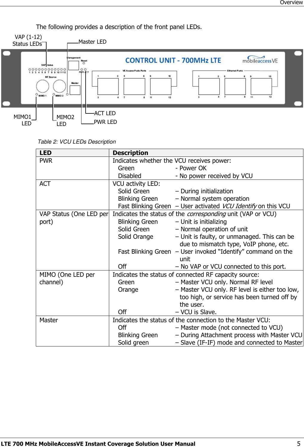
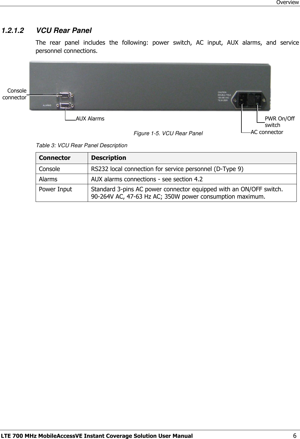
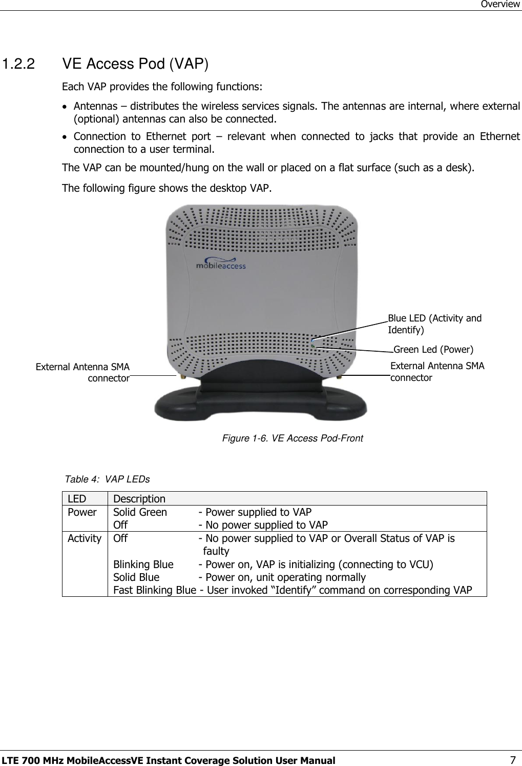
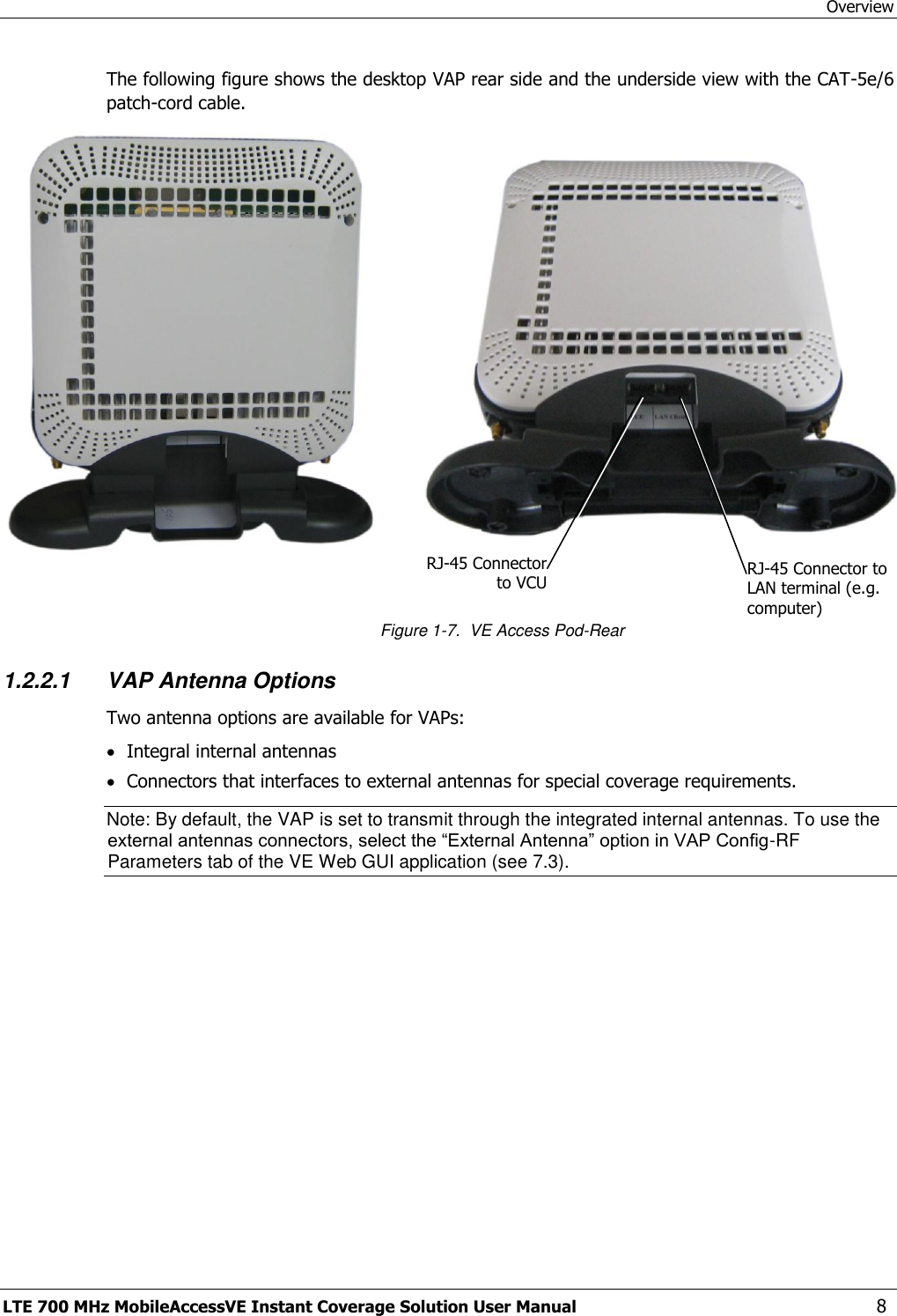
Corning Optical Communication VELTE700 VE DISTRIBUTED ANTENNA SYSTEM User Manual EnCOVER Dual Band

Corning Optical Communication Wireless VE DISTRIBUTED ANTENNA SYSTEM EnCOVER Dual Band

Users Manual

                          MobileAccessVE LTE 700 MHz MIMO Instant Coverage Solution User Manual P/N: 709C006201 REV: A00 Date: APRIL 2010
Preface Material LTE 700 MHz MobileAccessVE Instant Coverage Solution User Manual  II MobileAccess Worldwide Headquarters 8391 Old Courthouse Road Suite 300, Vienna, VA 22182 Tel: +1(866)436-9266, +1(703)848-0200 TAC: +1(800)787-1266, Fax: +1(703)848-0280 http://www.MobileAccess.com
Preface Material LTE 700 MHz MobileAccessVE Instant Coverage Solution User Manual  III  Preface Material  © Copyright 2010, MobileAccess Networks Inc. All Rights Reserved.   This document contains confidential and proprietary information of MobileAccess and may not be copied, transmitted, stored in a retrieval system or reproduced in any format or media, in whole or in part, without the prior written consent of MobileAccess. Information contained in this document supersedes any previous manuals, guides, specifications, data sheets or other information that may have been provided or made available to the user.   This document is provided for informational purposes only, and MobileAccess does not warrant or guarantee the accuracy, adequacy, quality, validity, completeness or suitability for any purpose of the information contained in this document. MobileAccess reserves the right to make updates, improvements and enhancements to this document and the products to which it relates at any time without prior notice to the user. MOBILEACCESS MAKES NO WARRANTIES, EXPRESS OR IMPLIED, INCLUDING, WITHOUT LIMITATION, THOSE OF MERCHANTABILITY AND FITNESS FOR A PARTICULAR PURPOSE, WITH RESPECT TO THIS DOCUMENT OR ANY INFORMATION CONTAINED HEREIN.  Policy for Warrantee and Repair MobileAccess tests and inspects all its products to verify their quality and reliability. MobileAccess uses every reasonable precaution to ensure that each unit meets their declared specifications before shipment. Customers should advise their incoming inspection, assembly, and test personnel about the precautions required in handling and testing our products. Many of these precautions can be found in this manual. The products are covered by the following warranties: General Warranty MobileAccess warrants to the original purchaser all standard products sold by MobileAccess to be free of defects in material and workmanship for one (1) year from date of shipment from MobileAccess. During the warranty period, MobileAccess will repair or replace any product that MobileAccess proves to be defective. This warranty does not apply to any product that has been subject to alteration, abuse, improper installation or application, accident, electrical or environmental over-stress, negligence in use, storage, transportation or handling. Specific Product Warranty Instructions All MobileAccess products are warranted against defects in workmanship, materials and construction, and to no further extent. Any claim for repair or replacement of units found to be defective on incoming inspection by a customer must be made within (30) days of receipt of shipment, or within (30) days of discovery of a defect within the warranty period.  This warranty is the only warranty made by MobileAccess and is in lieu of all other warranties, expressed or implied. MobileAccess sales agents or representatives are not authorized to make commitments on warranty returns.
Preface Material LTE 700 MHz MobileAccessVE Instant Coverage Solution User Manual  IV Returns In the event that it is necessary to return any product against above warranty, the following procedure shall be followed: 1. Return authorization is to be received from MobileAccess prior to returning any unit. Advise MobileAccess of the model, serial number, and discrepancy. The unit may then be forwarded to MobileAccess, transportation prepaid. Devices returned collect or without authorization may not be accepted. 2. Prior to repair, MobileAccess will advise the customer of our test results and any charges for repairing customer-caused problems or out-of-warranty conditions etc.  3. Repaired products are warranted for the balance of the original warranty period, or at least 90 days from date of shipment. Limitations of Liabilities MobileAccess's liability on any claim, of any kind, including negligence for any loss or damage arising from, connected with, or resulting from the purchase order, contract, quotation, or from the performance or breach thereof, or from the design, manufacture, sale, delivery, installation, inspection, operation or use of any equipment covered by or furnished under this contact, shall in no case exceed the purchase price of the device which gives rise to the claim.  EXCEPT AS EXPRESSLY PROVIDED HEREIN, MOBILEACCESS MAKES NO WARRANTY, EXPRESSED OR IMPLIED, WITH RESPECT TO ANY GOODS, PARTS AND SERVICES PROVIDED IN CONNECTION WITH THIS AGREEMENT INCLUDING, BUT NOT LIMITED TO, THE IMPLIED WARRANTIES OF MERCHANTABILITY AND FITNESS FOR A PARTICULAR PURPOSE. MOBILEACCESS SHALL NOT BE LIABLE FOR ANY OTHER DAMAGE INCLUDING, BUT NOT LIMITED TO, INDIRECT, SPECIAL OR CONSEQUENTIAL DAMAGES ARISING OUT OF OR IN CONNECTION WITH FURNISHING OF GOODS, PARTS AND SERVICE HEREUNDER, OR THE PERFORMANCE, USE OF, OR INABILITY TO USE THE GOODS, PARTS AND SERVICE. Reporting Defects The units were inspected before shipment and found to be free of mechanical and electrical defects.  Examine the units for any damage that may have been caused in transit. If damage is discovered, file a claim with the freight carrier immediately. Notify MobileAccess as soon as possible.  NOTE: Keep all packing material until you have completed the inspection Safety Warnings To comply with FCC RF exposure compliance requirement, adhere to the following warnings:  Warning! The Access Pod with its built-in antenna must be installed with a separation distance of at least 20cm from all persons and must not be located in conjunction with any other antenna.  Warning! The outside antenna must be installed with a separation of at least 20cm from all persons and must not be located in conjunction with any other antenna.  Warning! Use of this Access Pod with antennas other than those illustrated could be hazardous. Before using other antennas, contact MobileAccess Support.  Caution: Double pole/neutral fusing (two fuses in the appliance inlet)  Approved Antennas for use with the MobileAccessVE Solution The gain of external antennas connected to the VAPs should not exceed 10 dBi. Compliance with RF Safety Requirements MobileAccess products have no inherent significant RF radiation. The RF level on the down link is very low at the downlink ports. Therefore, there is no dangerous RF radiation when the antenna is not connected.
Preface Material LTE 700 MHz MobileAccessVE Instant Coverage Solution User Manual  V Certification and Compliance to Standards  Category Standards Safety: IEC 60950-1: 2003; UL-60950-1:2003; CAN/CSA – C22.2 No 60950-1-03 EMC: 47CFR 15.109 FCC Part 15 Radio: FCC Part 27 ISO 9001 2000 and ISO 13485: 2003
Preface Material LTE 700 MHz MobileAccessVE Instant Coverage Solution User Manual  VI About This Guide This guide provides essential product functionality with all the information necessary for proper installation and configuration of the MobileAccessVE system. List of Acronyms Abbreviation Description LTE Long Term Evolution MIMO Multiple Input Multiple Output PoE Power Over Ethernet PSE Power Sourcing Equipment SME Small / Medium Enterprise STP Shielded Twisted Pair UTP Unshielded Twisted Pair VAP VE Access Pod VCU VE Control Unit
 LTE 700 MHz MobileAccessVE Instant Coverage Solution User Manual  VII Table of Contents 1 Overview ............................................................................................................................. 1 1.1 System Architecture ..................................................................................................................... 2 1.2 System Elements ......................................................................................................................... 3 1.2.1 VE Control Unit (VCU) ......................................................................................................... 3 1.2.1.1 VCU Front Panel ..................................................................................................... 4 1.2.1.2 VCU Rear Panel ...................................................................................................... 6 1.2.2 VE Access Pod (VAP) .......................................................................................................... 7 1.2.2.1 VAP Antenna Options.............................................................................................. 8 1.3 System Monitoring and Management............................................................................................. 9 1.3.1 Integration with an External Fault Management System ........................................................ 9 2 Installation Workflow ....................................................................................................... 10 3 Infrastructure Requirements and Layout Planning ........................................................ 11 3.1 General Information on Location and Connections ....................................................................... 11 3.2 Infrastructure Requirements ....................................................................................................... 12 3.3 Coverage and Installation Planning ............................................................................................. 13 3.3.1 Types of Environments ..................................................................................................... 13 3.3.1.1 Standard Environment .......................................................................................... 14 3.3.1.2 Open Environment ............................................................................................... 14 3.3.1.3 Dense Environment: ............................................................................................. 14 3.3.1.4 Combination of Environments ............................................................................... 14 3.4 Planning VAP Layout .................................................................................................................. 15 3.4.1 RF Coverage Factors ......................................................................................................... 15 3.4.2 Mapping Locations ............................................................................................................ 15 3.4.3 Optional Directional Antennas ........................................................................................... 15 3.4.4 Installation Plan Example .................................................................................................. 15 4 VCU Unit Installation and Provisioning .......................................................................... 18 4.1 Installation of Master VCU .......................................................................................................... 18 4.2 Auxiliary Connections ................................................................................................................. 19 4.2.1 Alarm Output Connections ................................................................................................ 19 4.3 Installation of Slave VCU ............................................................................................................ 20 4.3.1 Connections of VAP Ethernet Cables .................................................................................. 22 4.3.2 Operation with LAN utilizing Power over Ethernet (PoE) ...................................................... 23
Table of Contents  LTE 700 MHz MobileAccessVE Instant Coverage Solution User Manual  VIII 4.4 Provisioning the VE Control Unit.................................................................................................. 24 4.4.1 Configure the Computer IP Parameters .............................................................................. 24 4.4.2 Provisioning the Master VCU Unit ...................................................................................... 25 4.4.3 Setting RF Parameters ...................................................................................................... 29 4.4.4 Verifying System Operation ............................................................................................... 31 4.4.5 Provisioning the Slave VCUs .............................................................................................. 33 5 VAP Installation and Provisioning .................................................................................. 35 5.1 VAP Installation ......................................................................................................................... 35 5.1.1 VAP Kit Contents .............................................................................................................. 35 5.1.2 VAP Locations and Mounting ............................................................................................. 36 5.1.2.1 Desk Mount ......................................................................................................... 36 5.1.2.2 Wall Mount .......................................................................................................... 37 5.2 Verifying VAP Coverage Area ...................................................................................................... 37 5.3 Naming the VAPs, Verifying Connections and Monitoring .............................................................. 38 5.4 Provisioning the VAPs ................................................................................................................. 38 5.4.1 Verifying Normal VAP Operation ........................................................................................ 38 5.4.2 Naming the VAP ............................................................................................................... 39 5.4.3 Configuring VAP for External Antenna ................................................................................ 40 6 Navigating the Web Access Application ........................................................................ 41 6.1 Opening a Session and Authentication Levels .............................................................................. 41 6.2 About the MobileAccessVE Web Access Window........................................................................... 42 6.3 Configuration Tab ...................................................................................................................... 43 6.3.1 Network Topology Tree .................................................................................................... 44 6.3.2 Configuration Display Area ................................................................................................ 45 6.4 Management Tab ....................................................................................................................... 46 7 VCU Monitoring and Configuration ................................................................................. 47 7.1 Viewing VCU General Information ............................................................................................... 47 7.2 Viewing VCU Alarms ................................................................................................................... 48 7.3 Master VCU RF Parameters ......................................................................................................... 49 8 VAP Monitoring and Configuration ................................................................................. 51 8.1 Viewing VAP General Information ............................................................................................... 51 8.2 Viewing VAP Alarms ................................................................................................................... 52 8.3 VAP RF Parameters .................................................................................................................... 53
Table of Contents  LTE 700 MHz MobileAccessVE Instant Coverage Solution User Manual  IX 9 Administrative Operations............................................................................................... 55 9.1 Changing Password .................................................................................................................... 55 9.2 IP Settings ................................................................................................................................ 56 9.3 SNMP Configuration Parameters ................................................................................................. 57 9.4 Upgrading (or Downgrading) VCU and VAP Software ................................................................... 58 9.4.1 Upgrading the VCU SW ..................................................................................................... 59 9.4.2 Upgrading the VAP SW ..................................................................................................... 60 10 Troubleshooting ............................................................................................................... 62 10.1 Finding a Specific VAP in the Building .......................................................................................... 62 10.2 Wireless Service is Not Available ................................................................................................. 64 10.3 PoE is Not Working .................................................................................................................... 64 10.4 Ethernet Service is Degraded ...................................................................................................... 65 10.5 No Service from Connected Access Pod ....................................................................................... 65 10.6 VCU Cannot be monitored via SNMP ........................................................................................... 67 Appendices ............................................................................................................................. 68 Traps ............................................................................................................................................... 68 VE Connections in Central Ethernet Source Topologies ........................................................................ 69
 LTE 700 MHz MobileAccessVE Instant Coverage Solution User Manual  1 1   Overview The MobileAccessVE LTE 700 MHz MIMO solution provides enhanced, cost effective, in-building LTE MIMO coverage for any small to large-sized enterprise environment. This solution is quickly and easily deployed using the existing Ethernet cabling infrastructure without affecting existing LAN services or performance.  The MobileAccessVE  solution distributes  LTE MIMO  service  to VE  Access  Pods  (VAPs)  installed throughout the enterprise and which distribute the services via integrated internal antennas (or optional  external antennas),  and provide  Ethernet  connectivity  (and  PoE pass-through)  to  LAN terminals.  VE seamlessly coexists with the Enterprise LAN and does not consume LAN capacity. The VAPs are distributed on each floor and plug into existing standard Ethernet jacks. They are powered via PoE technology and managed via a VE Control Unit (VCU) located in the floor’s telco closet.    For  site  coverage  that  requires  more  than  one  VCU,  several  VCUs  can  be  aggregated under  a  single  Master  VCU.  The  Master  VCU  provides  the  interface  to  the  carrier’s  capacity sources and management. This enhanced LTE 700 MIMO coverage solution can be quickly and easily installed with minimal disturbance  to  the  enterprise.  In  less  than  a  few  hours  and  with  no  additional  cables  being required, a scalable and flexible solution is provided at a significantly lower total installation cost. The following figures illustrate single-tier and multi-tier VE installations. In a  single-tier installation  the VCU  is connected  to  both the  service provider’s  equipment  and the Ethernet  switch, and distributes Ethernet and mobile services to up to  12  VAPs distributed over one more adjacent floors.  Figure 1-1. Single-Tier VE Installation Multi-tier installation includes the Master VCU that supports up to 12 Slave VCUs. In this type of installation the provider’s services are fed to the Master VCU through which the Slave VCUs are controlled and managed.
Overview LTE 700 MHz MobileAccessVE Instant Coverage Solution User Manual  2  Figure 1-2. Multi-Tier VE Installation 1.1  System Architecture Main Elements - The MobileAccessVE solution is based on the following main elements:   VE  Control  Unit  (VCU)  –  The  control  Unit  can  serve  as  either  a  Master  or  a  Slave  and interfaces the other VCUs (in case of Master) or the VAPs (when serving as Slave). The Master or  Slave  mode  is  automatically  detected  according  to  the  VCU's  physical  connection.  If  a connection  to  another  VCU  is  detected,  the  VCU  will  automatically  be  identified  as  a  Slave; otherwise it will assume the role of a Master.  Master  VE  Control  Unit  (Master  VCU)  –  installed  in  the  main  communication  Telco closet,  interfaces  to  the  service  provider’s  RF  capacity  sources,  and  provides  secure, central  management  to  up  to  twelve  VCUs,  as  well  as  all  connected  VAPs.  In  cases where no Slave VCUs are required, VAPs can be connected directly to the Master VCU.  Slave  VE  Control  Unit  (Slave  VCU) –  installed  in  the  telco/IDF  closet  and  used  to expand  coverage  to  additional  floors.  Each  VCU  interfaces  the  Master  VCU  and  up  to twelve VE Access Pods and twelve Ethernet connections.  The Slave  VCUs  distribute wireless  service signals to  each VAP along with  PoE  and (where relevant)  Ethernet  signals  from  the  Ethernet  switch,  throughout  the  existing  CAT-5e infrastructure.  The Slave VCUs are connected to the Master VCU using CAT-6 or 7 cables.  VE Access Pod (VAP) – These are pluggable antennas distributed at strategic locations over one or more floors to provide maximum coverage. VAPs provide RF coverage via integrated, internal antennas. VAPs are also equipped with an interface for external antennas for special coverage requirements. VAPs are remotely powered from the VCU using Power over Ethernet (PoE), eliminating the need for local powering. Up to twelve VAPs can be connected to a single VCU using LAN cables (CAT-5e or higher). Note:  When  the  total  number  of  VAPs  in  the  deployment  exceeds  72,  consult  with MobileAccess support.
Overview LTE 700 MHz MobileAccessVE Instant Coverage Solution User Manual  3 The following figure shows the Multi-tier VE LTE 700 MHz MIMO solution architecture.  Figure 1-3. VE Multi-Tier Basic Architecture The Master VCU distributes the wireless MIMO services from the service provider’s equipment to the  Slave  VCUs.  At  the  Slave  VCUs,  the  wireless  MIMO  services  are  converged  with  Ethernet service and routed to the VAPs via the Ethernet LAN CAT-5e/6 cabling infrastructure. The VAPs distribute the wireless LTE MIMO service via integrated internal antennas or (optional) external antennas and provide Ethernet/IP connectivity (and PoE pass-through) to the connected appliances such as WiFi APs and IP Phones. 1.2  System Elements This chapter describes the interfaces of the VE Control Units and Access Pods.  1.2.1  VE Control Unit (VCU) Capabilities and interfaces The VE Control Unit can operate as a Master VCU, managing up to twelve VCUs, or as a Slave VCU connected to up to twelve VAPs. While operating as a Master VCU:  Interfaces to RF source(s) and to VCUs  Converges Wireless services and distribution to Slave VCUs  Slave VCUs and VAP management and control   Remote management of the entire deployment While operating as a Slave VCU:  Interfaces to Master VCU  Converges Wireless services, Ethernet and PoE and interfaces to VAPs  Management and control of connected VAPs
Overview LTE 700 MHz MobileAccessVE Instant Coverage Solution User Manual  4 1.2.1.1 VCU Front Panel The  front  panel  supports  the  interfaces  to  the  wireless  LTE  MIMO  service  (two  channels  – corresponding  to  the  two  supported  TDD  MIMO  channels)  and  includes  interfaces  to  VAPs  or Slave VCUs (depending on the configuration). The  front  panel  also  interfaces  to  the  Ethernet  switch,  includes  a  connector  (Master)  for receiving the  wireless LTE  MIMO services  from  the Master VCU (in Master/Slave configuration) and the management interface.  The following provides the front panel ports.     Figure 1-4. VCU Front Panel Table 1: VCU Ports Description Ports Description MIMO1 MIMO2 RF  connections  (two  TDD  MIMO  channels)  to  the  service  provider LTE  Signal  Source  equipment.  N-Type  female  connectors.  Coax cables. Note:  When  supporting  SISO  service  –  only  MIMO  1  connector  is relevant. Management RJ45 WEB management connection. VE  Access  Pod  Ports 1-4; 5-8; 7-12  VAP/VCU port connections. RJ-45 connection to VAP/VCU through the LAN infrastructure. CAT-5e/6 cables. If VCU is  connected as Master  – these are connections to the Slave VCUs. If VCU is connected as Slave – these are connections to VAPs. Ethernet  Ports  1-4; 5-8; 7-12  Ethernet port connections to Ethernet Switch. Ethernet cables (used only in Slave VCUs). Master Used  for  connecting  a  Slave  VCU  to  the  Master  VCU  in  a  multi-tier deployment (connects to one of the VAP ports of the Master VCU). Reset  N/A in current version. Ethernet Ports 1-4; 5-8; 7-12 VAP Ports 1-4; 5-8; 7-12 Management  MIMO 2   MIMO 1   Master Port
Overview LTE 700 MHz MobileAccessVE Instant Coverage Solution User Manual  5 The following provides a description of the front panel LEDs.     Table 2: VCU LEDs Description LED Description PWR Indicates whether the VCU receives power: Green   - Power OK  Disabled   - No power received by VCU ACT VCU activity LED: Solid Green   – During initialization  Blinking Green   – Normal system operation Fast Blinking Green  – User activated VCU Identify on this VCU VAP Status (One LED per port) Indicates the status of the corresponding unit (VAP or VCU) Blinking Green   – Unit is initializing Solid Green   – Normal operation of unit Solid Orange   – Unit is faulty, or unmanaged. This can be due to mismatch type, VoIP phone, etc. Fast Blinking Green  – User invoked “Identify” command on the unit Off   – No VAP or VCU connected to this port. MIMO (One LED per channel) Indicates the status of connected RF capacity source:  Green   – Master VCU only. Normal RF level  Orange     – Master VCU only. RF level is either too low, too high, or service has been turned off by the user.  Off   – VCU is Slave. Master Indicates the status of the connection to the Master VCU:  Off   – Master mode (not connected to VCU) Blinking Green   – During Attachment process with Master VCU Solid green   – Slave (IF-IF) mode and connected to Master  PWR LED   ACT LED   VAP (1-12) Status LEDs    Master LED   MIMO1 LED   MIMO2 LED
Overview LTE 700 MHz MobileAccessVE Instant Coverage Solution User Manual  6 1.2.1.2 VCU Rear Panel The  rear  panel  includes  the  following:  power  switch,  AC  input,  AUX  alarms,  and  service personnel connections.   Figure 1-5. VCU Rear Panel Table 3: VCU Rear Panel Description Connector Description Console RS232 local connection for service personnel (D-Type 9) Alarms AUX alarms connections - see section 4.2 Power Input Standard 3-pins AC power connector equipped with an ON/OFF switch. 90-264V AC, 47-63 Hz AC; 350W power consumption maximum.  PWR On/Off switch AC connector AUX Alarms Console connector
Overview LTE 700 MHz MobileAccessVE Instant Coverage Solution User Manual  7 1.2.2  VE Access Pod (VAP) Each VAP provides the following functions:  Antennas – distributes the wireless services signals. The antennas are internal, where external (optional) antennas can also be connected.  Connection  to  Ethernet  port  –  relevant  when  connected  to  jacks  that  provide  an  Ethernet connection to a user terminal. The VAP can be mounted/hung on the wall or placed on a flat surface (such as a desk).  The following figure shows the desktop VAP.   Figure 1-6. VE Access Pod-Front   Table 4:  VAP LEDs LED Description Power Solid Green   - Power supplied to VAP Off   - No power supplied to VAP Activity Off   - No power supplied to VAP or Overall Status of VAP is  faulty Blinking Blue   - Power on, VAP is initializing (connecting to VCU)  Solid Blue   - Power on, unit operating normally Fast Blinking Blue - User invoked “Identify” command on corresponding VAP  Blue LED (Activity and Identify)  Green Led (Power)  External Antenna SMA connector   External Antenna SMA connector
Overview LTE 700 MHz MobileAccessVE Instant Coverage Solution User Manual  8 The following figure shows the desktop VAP rear side and the underside view with the CAT-5e/6 patch-cord cable.   Figure 1-7.  VE Access Pod-Rear 1.2.2.1 VAP Antenna Options Two antenna options are available for VAPs:  Integral internal antennas  Connectors that interfaces to external antennas for special coverage requirements. Note: By default, the VAP is set to transmit through the integrated internal antennas. To use the external antennas connectors, select the “External Antenna” option in VAP Config-RF Parameters tab of the VE Web GUI application (see 7.3). RJ-45 Connector to VCU  RJ-45 Connector to LAN terminal (e.g. computer)
Overview LTE 700 MHz MobileAccessVE Instant Coverage Solution User Manual  9 1.3  System Monitoring and Management The  MobileAccessVE  system  (Master  VCU,  Slave  VCUs,  and  VAPs)  is  centrally  managed  via  a single Web connection to the Master VCU.    The  basic  screen  in  the  GUI  is  the  Config  tab,  which  enables  the  user  to  view  the  system topology and setup parameters, Control Units, and all Access Pods connected to the Control Units. Note: When locally connecting to a specific Slave VCU, only the VAPs connected to this VCU can be  monitored.  However,  when  connected  to  the  Master,  the  entire  deployment  can  be monitored.   1.3.1  Integration with an External Fault Management System The MobileAccessVE  system  can be seamlessly  integrated  into any existing  Fault  Management (FM)  system  that  supports  SNMP  events.  The  Master  VCU  generates  a  SNMP  event  for  each relevant  system alarm  and forwards  this trap  to the  pre-configured  IP address  of the  external Fault Management system. 
Installation Workflow LTE 700 MHz MobileAccessVE Instant Coverage Solution User Manual  10 2   Installation Workflow The following figure summarizes the main steps of the installation procedure: Verify that all infrastructure requirements are met (includes verifying that the jacks are wired to the patch panel in the communication rooms).Check that Ethernet jacks are available in all planned VAP locations.Plan the floor coverage and VAP locations according to the type/density of the site.Installation WorkflowDetermine the communication rooms to which the VAP infrastructure  is connected (locations for the Slave VCUs).Install the Master VCU in the IDF/telco shaft.   CompleteOpen a local session to the Master VCU and configure the system parameters (IP, and service parameters: Central Frequency , Max expected Pin).Perform a “walk test” and verify coverage around the floor.Change VAPs locations or add VAPsMet Coverage? NoInstall the Slave VCUs and connect them to the Master VCU (verify that the VCU/VCH LED is green, and RF LEDs turned OFF).Install the VAPs and connect them to the Ethernet jacks. Connect the Ethernet appliance (if exists) to the VAP. Check that the VAP is operational (Blue LED lit). Check that Ethernet connection is OK.YesInstall the RF signal sources, connect them to the master VCU (through passive interfaces) and check that the RF signals are received by the VCU (i.e. that the RF LEDs are green). Connect the VCU VAP ports to the patch panel, and the Ethernet Switch to the VCU Ethernet ports.1. Infrastructure Preparation 2. Installation Procedure
Infrastructure Requirements and Layout Planning LTE 700 MHz MobileAccessVE Instant Coverage Solution User Manual  11 3   Infrastructure Requirements and Layout Planning 3.1  General Information on Location and Connections  Service  provider’s  RF  equipment  -  Macrocell,  Microcell,  Picocell,  Femtocell,  BDA,  etc. connects to the VCU through a passive interface.  VCUs:   Master VCU installed at the main IDF/telco cabinet and connected to all VCUs.  Slave VCUs  installed  at  the IDF/telco  cabinet  of each covered floor  and connected to the Master VCU, the Ethernet switch, and the VAPs through the cabling patch panel.  Wireless service signals from Master VCU to VCUs – routed through dedicated Ethernet CAT-6/7 cabling.  Wireless service signals from VCUs to the VAPs – routed through existing Ethernet CAT-5e/6 cabling infrastructure.   VAP  location  and  mounting  – wall  mounting  or  desk  mounting.  Connection  to  existing Ethernet jack (and external antenna if required).  VAP power  source -  No  power connections required.  VAPs are power  fed from VCU  using PoE (Power over Ethernet) technology.  Figure 3-1. VE Multi-Tier Basic Architecture
Infrastructure Requirements and Layout Planning LTE 700 MHz MobileAccessVE Instant Coverage Solution User Manual  12 3.2  Infrastructure Requirements Ethernet  standards  specify  that  the  maximum  distance  between  an  Ethernet  switch  and  an appliance  (computer,  WLAN  AP  etc)  should  not  exceed  100m  (300ft).    Therefore,  when  VE shares  the  IT  LAN,  the  maximum  distance  for  a  given  cable run cannot  be  longer  than  100m  (300ft)  between  the  Ethernet  switch  and  appliance,  including  all  patch  cords  (from  switch  to VCU, from VCU to patch panel, from RJ-45 outlet to VAP, and from VAP to appliance). Typically the horizontal cabling system will be connected to patch-panels in the communication rooms. The entire cabling system, including the patch panels and patch cords, should adhere to the CAT-5e/6 standard.  Specifically  all  pairs of the  CAT-5e  cable should  be  wired in  the patch panels (and patch cords).  1.  IDF/Telco closet space for one or more VCUs depending on the number and locations of the installed VCUs: (48.3cm x 51.3cm x 8.88cm) per VCU. Note: When planning the IDF/telco shaft, take the RF equipment (picocell/microcell or BDA) and the VCU into consideration. 2.  350 Watts of AC power to the VCU IDF/Telco closet. 3.  Building infrastructure:    CAT-5e/6 cabling, Shielded Twisted Pair (STP)  24 AWG minimum diameter for CAT-5e cabling  Dedicated  CAT-6/7  STP  cable  from  Master  VCU  to  Slave  VCUs  with  run  lengths  NOT exceeding 100m (300ft) and no shorter than 10m (33ft).  CAT-5e/6    STP  cable  from  VCU  to  each  VAP  with  run  lengths  NOT  exceeding  100m                                                                                                                                                     (300ft) and no shorter than 10m (33ft). VAPs can be connected over existing CAT-5e/6 cabling infrastructure and existing Ethernet jacks without affecting the LAN. Note: Verify with the IT department that the existing cables can support the VE installation. If available, review the infrastructure documentation to determine cable types and lengths. If  the  infrastructure  documentation  is  not  available,  attempt  to  visually  identify  the  cable type. Depending on the cable vendor, the cable type may be listed on the cable sheath. It is recommended to use a Fluke cable tester to measure  the cable length of the most remote VAPs. 4.  Master VCU Cable Connections:   2 x N-type female, 50 ohm interfaces to carrier equipment  Up to 12 x RJ-45 interfaces to Slave VCUs  1 x RJ-45 interface to Management  1 x D-Type 9 pins RS-232 interface for local craft  1 x D-Type 15 pins interface for External Alarms (dry contacts) 5.  Slave VCU Cable Connections  1 x RJ-45 interface to Master VCU (not used in small single-tier deployments)  12 x RJ-45 interfaces to VAPs   12 x RJ-45 interfaces to Ethernet Switch for LAN service   1 x D-Type 9 pins RS-232 interface for local craft
Infrastructure Requirements and Layout Planning LTE 700 MHz MobileAccessVE Instant Coverage Solution User Manual  13 3.3  Coverage and Installation Planning Note: The following section provides information required for planning the VAP installation on a single floor. In a multi-tier installation, this procedure is performed for each individual floor.  The  maximal  coverage  area  of  each  VAP  is  affected  by  the  density  and  type  of  environment being covered. Therefore, it is recommended to determine the location in two phases:  Plan the ideal location of each VAP in order to achieve complete coverage of the floor.  Select the exact location according to the location feasibility, where each VAP unit may be wall or desk mounted and an option for an external antenna is available. The supplied services (wireless only or Ethernet and wireless) depend on the jack to which the VAP is connected:   If  the  jack  supports  an  active  Ethernet  connection,  the  VAP  will  distribute  LAN  traffic  along with the wireless service. For more information see section 4.3.1.  If the jack is not currently active (not connected to an Ethernet switch), the VAP will distribute only the wireless services. This section provides  information  on coverage criteria  in  various types  of environments (Open, Standard, Dense and Merged) and provides rules-of-thumb for various installations of the VAPs.  Note:  Section 3.4  provides  a  detailed  example  of  installation  planning  in  various  types  of environment. It is recommended to review this example after reading this section. 3.3.1  Types of Environments This section describes the different types of installation environments and provides guidelines for best coverage of each type of space. The  coverage  guidelines  in  this  section  are  conservative  “rule  of  thumb”  estimates  of  RF coverage per VAP, meant to be used in scenarios  in which detailed designs are not performed. When the coverage layout is designed, the coverage per VAP is expected to  increase by up to 33%.  Coverage  estimates  in this  section  assume  25%  overlap  between  the  coverage  areas  of neighboring  VAPs  to  ensure  robust,  full  coverage  throughout  the  enterprise  with  no  “dead zones”.
Infrastructure Requirements and Layout Planning LTE 700 MHz MobileAccessVE Instant Coverage Solution User Manual  14 3.3.1.1 Standard Environment A traditional office environment with offices, hallways and scattered cubicles. Table 5: Standard Environment Installation Distances Signal Propagation from VAP 56 feet (19 m) Recommended Spacing between VAPs 112 feet (38 m) Recommended Maximum distance of VAPs from outer walls 56 feet (19 m) Coverage area per VAP 9,900 sqft (920 sqm) 3.3.1.2 Open Environment An  environment  with  minimal  obstacles  (e.g.  walls).  This  type  of  space  can  be  a  large conference or meeting room, cubical areas, lobby, or atrium. Table 6: Open Environment Installation Distances Signal Propagation from VAP 64 feet (21 m) Recommend spacing between VAPs 128 feet (42 m) Recommended maximum distance of VAPs from outer walls 64 feet (21 m) Coverage area per VAP 12,750 sqft (1,185 sqm) 3.3.1.3 Dense Environment: A dense environment  consists of a relatively large amount of walls, offices, equipment, tall file cabinets, bookshelves, and other items that could potentially impact the wireless signal. Examples include dense offices, hospitals, and manufacturing spaces. Table 7: Dense Environment Installation Distances Signal Propagation from VAP 41 feet (13.5 m) Recommended Spacing between VAPs 82 feet (27 m) Recommended Maximum distance of VAPs from outer walls 41 feet (13.5 m) Coverage area per VAP 5,300 sqft (495 sqm) 3.3.1.4 Combination of Environments In areas with  a combination of  environments,  place VAPs  on  the border  between  the  different environment types slightly closer to the denser area.  For example, in a cubical area with the outside wall having offices, simply locate the VAPs a little closer to the outside offices to provide coverage through the office walls. (See VAPs 11 and 13 in the floor  plan map  in  section  3.4.3.).  To ensure  maximal  coverage,  VAPs  can be  re-located or added. If a coverage gap is detected, the VAPs can be re-located until coverage gaps are filled.
Infrastructure Requirements and Layout Planning LTE 700 MHz MobileAccessVE Instant Coverage Solution User Manual  15 3.4  Planning VAP Layout  The following section describes the steps of planning VAPs along the covered floor. At the end of this section an example of a planning map is provided. Note: It is highly recommended to use a floor plan when planning the VAPs locations. 3.4.1  RF Coverage Factors It is important to note the type of factors that can severely impact RF coverage, and should be avoided:  Metallic  Structures  such  as  elevators,  high  file  cabinets,  and  some  moveable  metallic partitions severely degrade RF signals. All efforts should be made to locate VAPs in front of, or above metallic objects (desks, filing cabinets) to allow the signal to propagate.  Wall Materials such as concrete, tile, and cinderblock, as well as bathroom fixtures typically have fairly high signal attenuation and should be considered as dense spaces.  Types  of Glass  that  have  metallic  coatings  can  affect  RF  coverage,  typically  exterior  or mirrored. However this issue is not normally encountered inside a building. 3.4.2  Mapping Locations To map the VAP Locations 1.  Map out the available Ethernet  jack locations and mark all CAT-5e/6 drop locations on the floor plan map. TIP: The size and number of the ceiling tiles can be used to measure distances. 2.  Using  the  floor  plan  and  the  VAPs  coverage  guidelines  (as  given  in  section  3.4.3),  mark approximately where you would like to place each VAP in the facility.   VAPs may be added (or removed) at anytime for optimal coverage. 3.  For  each  jack  being  used  to connect  a  VAP,  check  if  the  jack  is already  connected  to  the Ethernet switch. . 4.  Connect the Ethernet cables corresponding to the selected jacks according to section 4.3.1. 5.  It is also recommended to check the area  where each  VAP will be  installed  to ensure    the installation is feasible. 3.4.3  Optional Directional Antennas Each  VAP  has  an  integrated  internal  antenna  that  provides  isotropic  radiation.  To  prevent interference  and  improve  coverage,  connect  directional  antennas  to  VAPs  installed  near  outer walls.  The VAP antenna parameter must be set accordingly via the Web GUI – see 8.3. 3.4.4  Installation Plan Example The Following figure shows a floor plan map with all required marks:
Infrastructure Requirements and Layout Planning LTE 700 MHz MobileAccessVE Instant Coverage Solution User Manual  16  Figure 3-2. Floor Plan Example Notes:  The red VAP coverage circles have an approximate radius of 41, 56 and 64 foot (13.5, 19 and 21  meters)  for  the  small,  medium  and  large  circles  respectively  (drew  according  to  the guidelines given in section 3.3.1.   VAP 3 is surrounded by the bathroom and stairwell which  are considered dense objects and would reduce coverage in that area by the other VAPs.  VAP  5  is  an  example  of  a  unit  that  provides  good  coverage  down  the  hallways  in an  Open Environment.  VAPs 11 and 13 are placed closer to the offices to provide better coverage to them, but on the open  side  will  actually  cover  a  much  greater  area.    This  is  why  the  coverage  is  larger  and shown here more as an oval than a circle.  The area between VAPs 7 and 14 would probably be the lowest coverage spot in the building because  of  the  bathrooms  and  stairwell  on  either  side.  If  after  the  system  is  installed,  this area is still a little low on coverage, a VAP can be added, but it may also be covered by VAP 14. Note: The plan can be modified at any time by moving the units around or by adding units. The  following  figure  depicts  an  actual  measured  quantified  coverage  of  a  floor  area  planned according to the above rules.
Infrastructure Requirements and Layout Planning LTE 700 MHz MobileAccessVE Instant Coverage Solution User Manual  17  Figure 3-3. Distributed VAPs propagation, 12dBm output power @ 1.8 GHz
VCU Unit Installation and Provisioning LTE 700 MHz MobileAccessVE Instant Coverage Solution User Manual  18  4  VCU Unit Installation and Provisioning This section describes the  installation  and configuration procedures  for  VE Control Units  (VCU) located  on  each  floor.  These  should  be  performed  only  after  planning  the  floor  coverage  and installation locations, as described in the previous sections. The VE VCU Kit includes: Table 8: VCU Kit Description Unit VE LTE 700 MHz MIMO Control Unit (VCU) Kit     Power Cord   VE SW CD  Local Configuration Cable (crossed RJ-45 cable)  Brackets for securing the VCU to a 19” rack (shipped assembled to the VCU)    4.1  Installation of Master VCU The VE Control Unit can be installed as a Master VCU and control up to (12) Slave VCUs and is installed  in  the  main  IDF/telco  closet.  This  section  describes  the  Master  VCU  installation procedures. 1.  Install the Master VCU in the main Telco closet. The Master VCU can be installed in a rack, placed on a shelf, or secured using the supplied bracket. 2.  Apply power to the Master VCU and verify that the PWR LED is lit. Also verify that the unit ACT LED completes initialization (blinking light) and shows a solid green light. 3.  Connect  (or  request  the  service  provider’s  service  personnel  to  connect)  the  provider’s signal source (Macrocell, Microcell, BTS, or BDA etc.) to the Master VCU front panel RF ports (through passive interface). Power on the signal sources.
VCU Unit Installation and Provisioning LTE 700 MHz MobileAccessVE Instant Coverage Solution User Manual  19 Note:  The  RF  Source  LED (see  following figure)  of the connected  port  on the  Master  VCU should be lit GREEN, indicating that the Master VCU senses the RF signal from the source at the expected level (according to Max Expected Pin). After connecting the capacity source, if the LED remains RED verify that the Max Expected Pin is configured properly and service is enabled. 4.  Connect  the  Master  VCU VAP ports  to the  Slave VCUs VCU/VCH ports  via  the  patch-panel that feeds the dedicated CAT-6/7 cabling system.      NOTE: After the Slave VCUs are connected (according to section 4 ), verify that that the Master VCU  VAP  Status  LEDs  which  correspond  to  the  connected  Slave  VCUs  complete  initialization (blinking light) and show a solid green light. 4.2  Auxiliary Connections The auxiliary connections  are performed through the  Master  VCU rear panel Alarms port. See following figure.   4.2.1  Alarm Output Connections The  controller  can  provide  Major  and  Minor  Output  Alarms.  These  alarms  can  be  connected directly  to  either  the  auxiliary  input  of  the  Base  Station  or  to  any  additional  dry-contact application. A Major Alarm is generated when there is an alarm condition in one or more VCUs, while a Minor Alarm is generated when there is an alarm condition in one or more of the VAPs. RF ports  Note: When functioning as a Master VCU, the control units’ Ethernet Ports are not relevant and should not be used. VAP Ports 1-4; 5-8; 7-12 ACT LED  VAP Status LEDs Alarms port for auxiliary connections
VCU Unit Installation and Provisioning LTE 700 MHz MobileAccessVE Instant Coverage Solution User Manual  20 Note: If  only  one  alarm  is  required  (Minor  or  Major)  an external  connection  of  a  wire  jumper between pins 8 and 13 is necessary (normally closed). Connect the relevant alarms according to the connector pinout below.     Table 9. Alarms Connector – used pins 8 – Major Error Signal (normally closed) 7 – Minor Error Signal (normally open) 11 – Major COM  12 – Minor COM 15 –Major Error Signal (normally open) 13 – Minor Error Signal (normally closed) 4.3  Installation of Slave VCU 1.  Install the Slave VE Control Unit (VCU) in the Telco closet corresponding to the  floor being covered. The Slave VCU can be installed in the rack using the supplied bracket in the IDF closet. Apply power to the Slave VCUs and note that the VCU PWR LED is lit. Note that the unit ACT LED completes initialization (solid light) and shows a blinking green light. See  Figure 4-1.          Figure 4-1. VCU PWR, RF and Master LEDs 2.  Connect the Slave VCU front panel Master port to the Master VCU VAP port via the patch panel  using  dedicated  CAT6  cables.  Verify  that  the  Master  LED  completes  initialization (blinking light) and shows a solid green light. The (RF) MIMO LEDs (of both services) should turn OFF.  11 15 8 Major Alarm 12 7 13 Minor Alarm PWR LED   Master LED  RF Source LEDs  (one per service)
VCU Unit Installation and Provisioning LTE 700 MHz MobileAccessVE Instant Coverage Solution User Manual  21  Figure 4-2. Master and Slave VCU Connections 3.  Connect the Slave VCU VAP ports to the patch-panel that feeds the existing structured CAT-5e/6 cabling system. 4.  According  to  VAPs  layout  plan  (as  explained  in section  3.4.2)  connect  the  Ethernet  switch cables (see section 4.3.1 for more detailed explanation).  If the requested jack is already in use, disconnect it from the Ethernet switch and re-connect it to the corresponding Ethernet port in the Slave VCU front panel.
VCU Unit Installation and Provisioning LTE 700 MHz MobileAccessVE Instant Coverage Solution User Manual  22 4.3.1  Connections of VAP Ethernet Cables For  VAPs  installed  on  currently  ACTIVE  Ethernet  ports,  shift  the  relevant  Ethernet  LAN connections as follows.
VCU Unit Installation and Provisioning LTE 700 MHz MobileAccessVE Instant Coverage Solution User Manual  23 For VAPs installed on currently INACTIVE Ethernet ports, connect as follows.  NOTE: After the Slave VCUs are installed and connected to the correct ports in the patch panels, please proceed with the VAP installation as described in chapter 5 . However, it is recommended to complete the VCU provisioning first (see section 4.3.2) because when installing the VAPs they will instantly provide the wireless service (and the installer will be able to check the coverage). 4.3.2  Operation with LAN utilizing Power over Ethernet (PoE) Power  over  Ethernet  (PoE)  is  a  technology  that  enables  passing  electrical  power  over  the Ethernet  cabling.  Power  can  either  come  from  a  PoE-enabled  Ethernet  device  (e.g.  switch)  or from a “mid-span” device built specifically for "injecting" power into the Ethernet cabling. PoE can operate over two different pairs in a CAT-5e/6 cable. These two methods are referred to as “alternative a” and ”alternative b”. All PoE compatible appliances, such as WLAN APs and IP Phones,  support  both  alternatives  and  automatically  detect  and  use  the  power  on  the appropriate pairs (alternative a or b).     MobileAccessVE  supports  sharing  LAN  infrastructures  that  use  either  802.3af  PoE  or  802.3at PoE.  In the current release MobileAccessVE supports operation with “alternative a” PoE. Note: Future enhancements will support coexistence with “alternative b” PoE. If this is currently required, consult MobileAccess.
VCU Unit Installation and Provisioning LTE 700 MHz MobileAccessVE Instant Coverage Solution User Manual  24 4.4  Provisioning the VE Control Unit This  chapter  describes  how  to  set  the  basic  parameters  required  for  operation  and  remote management  of  the  Master  VCU  using  the  Web  GUI.  The  configuration  dialogs  are  fully described in Chapter 0. The Master or Slave mode is automatically detected according to the VCU's physical connection. If a connection to another VCU is detected, the VCU will be identified as a Slave, otherwise it will assume the role of a Master. Notes:  1. The initial  configuration of  the  Master  VCU is  performed  via local  connection using  a  cross-cable  and  connecting  to  VCUs  default  IP  address.  After  performing  the  initial  configuration and assigning the Master VCU an IP address, the system can be connected, monitored, and configured via a remote management connection. 2. The configuration and management of all of the system units (VCUs and VAPs) is performed via local or remote connection to the Master VCU unit. 4.4.1  Configure the Computer IP Parameters Configure the computer local LAN connection to operate in the same subnet as the default VCU IP  address.  Note  that  the  procedure  may  vary  slightly  depending  on  the  operating  system installed on your computer. The following procedure is for Windows XP. To configure the computer’s IP parameters: 1.  Click the Start menu and choose Control Panel. 2.  In the Control Panel, click Network and Internet Connections. 3.  Click Network Connections and then double-click Local Area Connection. The Local Area Connections Properties dialog box appears with the General tab displayed by default.  4.  In the Items list, select “Internet Protocol (TCP*IP)” and click the Properties button.  5.  The “Internet Protocol (TCP/IP) Properties” dialog appears.
VCU Unit Installation and Provisioning LTE 700 MHz MobileAccessVE Instant Coverage Solution User Manual  25 NOTE: The Master VCU is supplied with the default IP address 192.168.1.1.  In order to communicate with the unit, it is necessary to assign your computer a Static IP address in the same subnet: 192.168.1.2 to 192.168.1.250.  (i.e. 192.168.1.9 as shown in the example).  Define the subnet mask as shown: 255.255.255.0  6.  Click OK.  7.  The computer  communication  parameters  are now  defined  and  you can  open  a session  to the Master VCU and provision the unit. 4.4.2  Provisioning the Master VCU Unit 1.  Perform a local connection to the Master VCU unit by connecting the Master VCU front panel Management port and a laptop computer.   2.  Open  a  web  browser  and  type  the  Master  VCU  IP  address  in  the  address  bar  (Default: 192.168.1.1).
VCU Unit Installation and Provisioning LTE 700 MHz MobileAccessVE Instant Coverage Solution User Manual  26 The Login window appears.  3.  Type the User Name “engineer” and enter the Password “eng”.  The MobileAccessVE Web GUI appears.  4.  Choose the Management tab in the main menu bar and click the IP Settings tab on the side bar.  Network Topology Tree Sub-tabs that correspond to each main tab Main Menu Bar Modify button IP Settings
VCU Unit Installation and Provisioning LTE 700 MHz MobileAccessVE Instant Coverage Solution User Manual  27 Note: See section 6.4 for a description of the Management tab. 5.  Click the Modify button to define the STATIC IP Address according to existing LAN.  Note:  After  the  initial  IP  configuration,  the  Master  VCU  can  be  accessed  remotely  via Ethernet.   Set the Static IP address parameter (DHCP is not currently available) Default definitions: • The Default IP Address : 192.168.1.1 • The Default Subnet Mask: 255.255.255.0 • The Default Gateway: 192.168.1.254  Click OK. 6.  Log out and then log in again with the new IP settings. 7.  Select the Config tab in the main menu bar. Note: See section 6.3 for a complete description of the Config tab.
VCU Unit Installation and Provisioning LTE 700 MHz MobileAccessVE Instant Coverage Solution User Manual  28 8.  The Master VCU appears in the Network Topology Tree as VCU-M. Select the Master VCU by clicking on it.   9.  Before configuring the Master VCU it is recommended to give the unit an indicative name. To assign the Master VCU an indicative name:  Select the Module Info Tab and click the Modify button.   Click Modify Config Tab Master VCU
VCU Unit Installation and Provisioning LTE 700 MHz MobileAccessVE Instant Coverage Solution User Manual  29  Type the unit name (up to 17 alpha-numeric characters) in the Controller Name dialog and click OK.  4.4.3  Setting RF Parameters In a Master-Slave mode (multi-tier architecture) the RF parameters are only configured for the Master VCU unit. Set the RF parameters according to the LTE Signal Source transmission configuration (MIMO or SISO). Each type of configuration is defined through a dedicated tab.  This section describes the MIMO and the SISO configuration procedures.  To configure the MIMO RF parameters: 1.  Select the Master VCU in the topology tree and then select the RF Parameters tab. Verify that the Service Mode parameter is defined as MIMO.  Click to modify DL CF
VCU Unit Installation and Provisioning LTE 700 MHz MobileAccessVE Instant Coverage Solution User Manual  30 2.  Click the DL CF Modify button. Enter the Base Station central frequency and click OK.  Note: The MIMO DL CF parameter defines the same DL central frequency for Channel 1 and Channel 2. 3.  Define Max expected power of BTS (0-33dBm). 4.  Define Rx System Gain (-15 to 5dB) Notes:  Max expected Pin and DL CF parameters can be obtained from your service provider. The remaining parameters are predefined to their default values. (Service Bandwidth is set to 10MHz per channel). Any  updates  of  the  service  definition  (DL  CF  or  Service  Mode)  are  sent  to  all  connected VAPs. To configure the SISO RF parameters: Note: The RF tab is displayed for MIMO by default. 1.  Select the Master VCU in the topology tree and select the SISO option in the Service Mode drop-down list. The RF parameters tab will display the SISO RF parameters.    2.  Click the DL CF Modify button and enter the Base Station central frequency. Click OK.  3.  Define Max expected power of BTS (0-33dBm). Service Mode drop-down list
VCU Unit Installation and Provisioning LTE 700 MHz MobileAccessVE Instant Coverage Solution User Manual  31 4.  Define Rx System Gain (-15 to 5dB) Notes:  Max expected Pin and SISO DL CF parameters can be obtained from your service provider. The remaining parameters are predefined to their default values. (Service Bandwidth is set to 10MHz). Any  updates  of  the  service  definition  (DL  CF  or  Service  Mode)  are  sent  to  all  connected VAPs. 4.4.4  Verifying System Operation To verify proper operation of the system, refer to the  VCU Alarms and Mask sub-tab (in the Config tab). The following figure illustrates the MIMO alarms.  Note: SISO alarms are similar, however only Channel 1 alarms appear. 1.  Verify that all the alarms are GREEN. Refer to the alarm descriptions in the following table. Note: When SISO service is used only the Channel 1 alarms are relevant. Alarm Description VCU Faulty RED - VCU fault. Remove and re-apply power to VCU. If problem persists, replace VCU. Over Temperature Temperature of unit exceeds normal range. Service Off User has disabled the service. Channel 1 RF Tx Pwr Low RED - DL RF Power is lower by 15dBm (or more) from the Max Expected Pin. Channel 1 RF Tx Pwr High RED - the input power exceeds the maximum expected Pin by more than 3 dB. Channel 2 RF Tx Pwr Low RED - DL RF Power is lower by 15dB (or more) from the Max Expected Pin. Channel 2 RF Tx Pwr High RED - the input power exceeds the maximum expected Pin by more than 3 dB.  Overall Status Indicates Fault (RED) level or GREEN if there are no faults.
VCU Unit Installation and Provisioning LTE 700 MHz MobileAccessVE Instant Coverage Solution User Manual  32 Note: To  briefly check  the VCU status,  click on the  VCU name in  the  Topology Tree.  The  VCU icon will appear, showing the LEDs status.  2.  Mask irrelevant alarm conditions to avoid affecting the overall status of the unit. See For Example NOTE: Tx signal refers to the DL signal from the BS side towards the remote units (VAPs). In the example below “Channel 2 RF Tx Pwr High” alarm is masked (disabled)  – this is the alarm for the DL signal (from the BS side). The left dialog shows the alarm response when MIMO2 Tx RF Pwr High alarm is enabled and a fault corresponding  to  that alarm is  detected. (MIMO2 Tx RF Power  exceeds the defined range).  The Overall Status will be RED indicating a fault. The right dialog shows the alarm response when MIMO2 Tx RF Pwr High alarm is disabled (MASKED). The MIMO2 Tx RF Pwr High LED be RED; but, the Overall Status will be GREEN – showing NO Fault.                                       Figure 4-3. Service2 Service Off Alarm – Not Masked       Figure 4-4. . Service2 Service Off Alarm –Masked Channel2 RF Tx Pwr High alarm masked (disabled) Channel2 RF Tx Pwr High alarm unmasked (enabled)  Overall status RED - accordingly  Click VCU Master Overall status GREEN- accordingly
VCU Unit Installation and Provisioning LTE 700 MHz MobileAccessVE Instant Coverage Solution User Manual  33 In  Figure  4-4  above,  the  alarm  condition  for  “Service2  Service  Off”  actually  exists,  while  the masking prevents this condition from affecting the overall status of the system and therefore the Overall Status led below is green. Note: To  briefly check the VCU status, click  on the  VCU name  in the Topology  Tree. The  VCU icon will appear, showing the LEDs status.   4.4.5  Provisioning the Slave VCUs Note: The Slave VCUs management and configuration is performed through a remote connection to the Master VCU, via the web management. Before provisioning the Slave VCUs verify that the Master VCU unit, to which it is connected, has been provisioned (see section 4.4.1). The  Slave  VCU  RF  parameters  are  set  via  the  Master  VCU,  therefore  there  is  no  need  to configure the  RF parameters individually  for  each  connected  Slave  VCU. It  is recommended  to assign each Slave VCU an indicative name. Master VCU icon
VCU Unit Installation and Provisioning LTE 700 MHz MobileAccessVE Instant Coverage Solution User Manual  34 To assign a name to a Slave VCU: 1.  Connect to the Master VCU unit (either locally as explained in section 4.4.1 or remotely) and select the Slave VCU to be provisioned from the Network Topology Tree.   Each VCU has a default name of the form “VCUPx-name”, where:  Px - Master VCU port number to which the Slave VCU is connected  Name - user-defined name 2.  To assign the Slave VCU an indicative name:  Select the Module Info Tab  Click the Modify button   Type the unit name (up to 17 alpha-numeric characters) and click OK.  Click Modify Selected Slave VCU-
VAP Installation and Provisioning LTE 700 MHz MobileAccessVE Instant Coverage Solution User Manual  35  5  VAP Installation and Provisioning This  section  provides  a  description  of  the  VE  Access  Pods (VAPs)  installation,  verification,  and monitoring procedures. 5.1  VAP Installation The  VAPs  installation  procedure  consists  of  connecting  each  VAP  to  the  Ethernet  jack  in  the appropriate location to provide optimal coverage (see sections 3.4 and 5.1.2). 5.1.1  VAP Kit Contents The LTE 700 MHz VE Access Pod (VAP) Kit includes:  Note: VAPs are provided with two mounting options: Desk Mount and Wall Mount. Table 10: VAP Kit Kit Items UNIT  VE Access Pod (VAPs)                         Wall Mount Adaptor (with double sided sticky tape located on rear for fast installation)                       Desk Mount Adaptor  8 Screws: o 4 Short Screws – for securing adaptor to pod o 4 Longer Screws – for securing wall mount adaptor to the wall (“anti-theft” installation)           RJ-45 Jumper Cable  Front Rear – showing tape  Long screws Short screws
VAP Installation and Provisioning LTE 700 MHz MobileAccessVE Instant Coverage Solution User Manual  36 5.1.2  VAP Locations and Mounting  It is recommended to place the VAPs on top of desks, cubical walls, filing cabinets, or higher on walls so as to maximize the provided coverage per VAP. Note:  Mounting  a  VAP  beneath  a  desk  or  in  another  secluded  location  (e.g.  office  corner) decreases the effective coverage of the VAP increasing the need for a higher number of VAPs to cover the same area. When installing the VAPs, consider the following:  Placing units in an open area.  Availability of CAT-5e/6 infrastructure.  The VAPs plug into standard (RJ-45) Ethernet connection jacks.  If the jack being used is already connected to Ethernet switch. For more information see 3.4.2 and 4.3.1.  Aesthetics of the VAP location. 5.1.2.1 Desk Mount  Note: All components (adaptor, screws, and cables) are included in the VAP Kit.  Place the VAP on the Desk Mount.   Secure the Desk Mount adaptor to the VE Access Pod using the (4) short screws.   Connect the RJ-45 jumper cable (CAT-5e/6) to the VAP’s RJ-45 connector.  Place the VAP on a flat surface according to the planned location.  Plug the other end of the cable into the VCUs (RJ-45) Ethernet jack.   When using an external antenna, connect the Ext. Antenna SMA connector(s) to the external antenna(s).  This option must be  SW  configured via the web GUI. (Note: Internal antenna is enabled by default). Note: The maximum external antenna gain should not exceed 10 dBi.  Verify that the VAP receives power and connects to the VCU via the LEDs on the unit (both the GREEN LED and the BLUE LED should be lit).    Desk Mount Adaptor Ext. Antenna SMA connectors* RJ-45 to computer RJ-45 to VCU  Access Pod Assembly - Front View Assembly - Rear View Activity – Blue LED Pwr – Green LED + =
VAP Installation and Provisioning LTE 700 MHz MobileAccessVE Instant Coverage Solution User Manual  37  5.1.2.2 Wall Mount  Note: All components (adaptor, screws, and cables) are included in the VAP Kit.  Attach  the  VAP’s  wall  mount  adaptor  to  the  wall  in  the  planned  location,  using  the  double sided sticky tape located on the rear or secure it using the longer screws.   Place the VAP on the Wall Mount.   Secure the Wall Mount adaptor to the VE Access Pod using the (4) short screws.   Connect the RJ-45 jumper cable (CAT-5e/6) to the VAP’s RJ-45 connector.  Plug the other end of the cable into the VCUs (RJ-45) Ethernet jack.  When using an external antenna, connect the Ext. Antenna SMA connector(s) to the external antenna(s).  This  option  must  be  SW  configured  via  the  web  GUI.  (Note:  Internal antenna is enabled by default). Note: The maximum external antenna gain should not exceed 10 dBi.  Verify that the VAP receives power and connects to the VCU via the LEDs on the unit (both the GREEN LED and the BLUE LED should be lit).  +    =     5.2  Verifying VAP Coverage Area Verify  coverage  in  the  areas,  adding  and  moving  VAPs  for  optimal  coverage  according  to  the principles described in 3.3. Access Pod Wall Mount Adaptor Assembly Blue LED Green LED
VAP Installation and Provisioning LTE 700 MHz MobileAccessVE Instant Coverage Solution User Manual  38 5.3  Naming the VAPs, Verifying Connections and Monitoring 5.4  Provisioning the VAPs Note:  This  section  provides  only  the  information  required  for  provisioning  the  VAPs.  For a  full description of the VAP configuration options, refer to section 0. The  VAPs  are  auto-discovered  by  the  VCU  and  can  be  monitored  via  a  remote  or  a  local connection  (to  the  Master  VCU).  The  VAPs  are  auto-configured  by  the  VCU  without  user intervention  (no  configuration  procedure  is  required).    However,  if  you  wish,  you  may  assign each VAP an identifiable name corresponding to its physical location.  The only required configuration is for VAPs to which external antennas are connected. 5.4.1  Verifying Normal VAP Operation Use the RF Parameters and Module Info sub-tabs to review the VAP information and status.   1.  If a session in not already open to the MobileAccessVE Web GUI application, open a session to the Master VCU according to section 4.4.2. 2.   Select a VAP from the Network Topology Tree.    Each VAP has a default name showing the number of the Slave VCU port to which the VAP is connected. 3.   To verify normal operation of the VAP:  In  the  Network  Topology  Tree,  under  the  Control  Unit,  verify  that  a  GREEN  LED  is displayed (either RED or GREEN) for each connected VAP.    If the VAP LED is RED, select the VAP from the network topology tree then select the Config tab. Refer to the Alarms tab work area. Use the displayed alarms to identify the problems.
VAP Installation and Provisioning LTE 700 MHz MobileAccessVE Instant Coverage Solution User Manual  39  Note 1: VAP alarm mask is saved in the VCU, associated with the port to which the VAP is connected.  In  case  you  replace  the  VAP,  the  newly  installed  VAP  will automatically  be  set with same alarm mask. Note 2: For more information on the VAP Alarms, refer to section 8.2. 5.4.2  Naming the VAP To assign the VAP an identifiable name:  Open the Config Module info tab.     Click the Modify button.  Type the unit name (up to 17 alpha-numeric characters) and click OK.
VAP Installation and Provisioning LTE 700 MHz MobileAccessVE Instant Coverage Solution User Manual  40 5.4.3  Configuring VAP for External Antenna By default, the VAPs are set to operate using the internal antennas.  Use the procedure described in this section to configure all VAPs to which external antennas are connected.  To configure for operation with external antennas  Select the relevant VAP from the Topology Tree.  Select the RF Parameters sub-tab.  Set the Channel 1/2 antennas as External.
Navigating the Web Access Application LTE 700 MHz MobileAccessVE Instant Coverage Solution User Manual  41  6   Navigating the Web Access Application  The  MobileAccessVE  Web  management  application  is  accessed  through  any  standard  web browser connected to the Master VCU via a network within the same subnet as the Master VCU or a different subnet which is routable. 6.1  Opening a Session and Authentication Levels After the initial configuration (as explained in 4.4.1) the MobileAccessVE system can be accessed via the network.  To access the system: 1.  Open a web browser.  In the address bar type the Master VCU’s IP address as you set it in the Master VCU configuration operation (see section 4.4.1).  2.  The Login pane appears.   Enter your User Name and password. The following authentication levels are available:  Level Default Password Access  operator oper  This user has Read Only access. engineer eng This user has access to basic configuration options. admin ma98 This user has Field Engineer permissions, in addition to access to changing passwords.
Navigating the Web Access Application LTE 700 MHz MobileAccessVE Instant Coverage Solution User Manual  42 6.2  About the MobileAccessVE Web Access Window The MobileAccessVE Web window includes six main tabs that provide access to the applications’ main options. Here the Config tab is displayed by default. Note: The Monitor, Events, Setup, and Help tab are future options.  The appearance of the  each screen  varies according  to the tab displayed. The Main  Menu Bar tabs are:  Config(uration)  – Displayed  by default  upon  login. Provides  the  selected  units’  configuration parameters and alarms  Management -  Provides upgrade, IP configuration and security options Both of these tabs are described in detail in the following sections     Menu bar Sub-tabs corresponding to menu bar options
Navigating the Web Access Application LTE 700 MHz MobileAccessVE Instant Coverage Solution User Manual  43  6.3  Configuration Tab The  Configuration  tab  provides  the  general  information  and  service  RF  parameters  for configuration of the units appearing in the Network Topology tree.  To access a VCU Configuration tab On the left hand side of the window select a Master VCU/Slave VCU from the network topology tree.  Select  the  Configuration  tab  from  the  menu-bar.  The  information  and  parameters displayed in the Configuration sub-tabs vary depending on whether a VCU or VAP is selected in the topology tree. The Configuration tab is divided in to three main areas:  Network Topology Tree – Displays the system units (Master VCU, Slave VCUs and VAPs) and their status  Display Area – Displays the icon of the selected unit including the LED statuses  Work Area – Displays the Module Info, alarms, and RF tabs corresponding to the unit selected in the topology tree (Master VCU, Slave VCU or VAP)     Selected VCU VCU Icon display Configuration tab
Navigating the Web Access Application LTE 700 MHz MobileAccessVE Instant Coverage Solution User Manual  44 6.3.1  Network Topology Tree The Configuration Network Topology Tree appears on the left hand side when the Config tab is selected, and displays the Master VCU, Slave VCUs, and VAPs in two levels:  First Level – VCU  Second Level – Up to 12 VAPs Note: The root is MobileAccess VE.  Each unit is assigned a Type Px-name:  Type – VCU-M, VCU or VAP (for Master VCU, Slave VCU or VE Access Pod)  Px - VCU port number   Name – user defined Each unit is displayed with a colored bullet that indicates its’ status: Color Indicates Green OK  Red Alarm Condition   The root (the entire MobileAccessVE site) is also associated with a colored bullet that indicates the overall status of the deployment: Color Indicates Green OK  Red Alarm Condition in one or more VCUs or VAPs Root Master VCU – first level VAP – second level
Navigating the Web Access Application LTE 700 MHz MobileAccessVE Instant Coverage Solution User Manual  45 6.3.2  Configuration Display Area When  selecting  an  element  (Master  VCU/Slave  VCU  or  VAP)  in  the  network  topology  tree,  an icon representing the unit is displayed in the Configuration tab display area.  Icon display area
Navigating the Web Access Application LTE 700 MHz MobileAccessVE Instant Coverage Solution User Manual  46 6.4  Management Tab The Management tab provides user administrative management options and includes the sub-menu tabs:  Firmware – Used for upgrading/downgrading SW to VCUs  Distribute – Used for distributing the upgrade/downgrade SW files to the VAPs  Security – Used for changing user passwords  SNMP Config –  Used for defining the SNMP communities and trap destinations  IP Settings – Used for viewing and modifying the network parameters  Sys(tem) Log – N/A The following figure shows the Management screen with the menu options on left.
VCU Monitoring and Configuration LTE 700 MHz MobileAccessVE Instant Coverage Solution User Manual  47 7   VCU Monitoring and Configuration  7.1  Viewing VCU General Information The VCUs general information (such as unit name and SW versions) can be viewed in the Config Module Info sub-tab. The tab includes two additional options:  Identify  button  -  Enabling  this  option  enables  finding  the  physical  location  of  the  selected element  (see  10.1).  When  this  option  is  set  to  ON,  the  LEDs  on  the  corresponding  VCU flickers.  Reset button - SW reset of the unit To view VCU general information  Click the Config tab from the main menu and select the VCU from the network topology tree. The Module Info sub-tab is displayed by default.  The following information is displayed: Field Description Name User defined name for system element (up to 17 characters) Serial Number Factory set ID number Product Revision Revision number of VCU/VAP
VCU Monitoring and Configuration LTE 700 MHz MobileAccessVE Instant Coverage Solution User Manual  48 Field Description SW Active Version Version of the SW currently being used to manage and monitor the system SW Inactive Version Version  of other system SW version not in use Identify Button Enabling this option enables finding the physical location of the selected element (see 10.1). When this option is set to ON, the LEDs on the corresponding VAP/VCU flickers. Reset Button SW reset of the unit 7.2  Viewing VCU Alarms The  alarms  displayed  in  the  Alarms  tab  correspond  to  the  VCU  (Master/Slave)  selected  in  the topology tree. When a VCU element is selected in the topology tree, the Alarm tab displays the main alarms in the unit. To view VCU Alarms  In the Topology Tree select the Control Unit (VCU) then click the Config(uration) tab in the menu bar located at the top of the window.  Refer to the VCU Alarms and Mask sub tab.  If one or more alarms occur, the corresponding Status indicator will be illuminated in RED. If the VCU is OK and no fault occurs, the Overall Status indicator will show GREEN.
VCU Monitoring and Configuration LTE 700 MHz MobileAccessVE Instant Coverage Solution User Manual  49  Alarm Description VCU faulty Hardware fault detected in VCU Over temperature Temperature of unit exceeds normal range Mismatch VCU service type is different from VAP service type Channel 1/2 DL RF Pwr Low   DL RF Power is lower by 15dBm (or more) from the Max Expected Pin. Note: Channel 2 alarm is not displayed when SISO service is used. Channel 1/2 DL RF Pwr High Input power exceeds the maximum expected Pin by more than 3 dB. Note: Channel 2 alarm is not displayed when SISO service is used. Service Off User has disabled the service Overall status Indicates Fault (RED) level if there are (unmasked) faults, or GREEN if there are no faults 7.3  Master VCU RF Parameters Note: The RF parameters are not displayed for control units functioning as Slave VCUs.  To access the Service RF tab Click the Config tab from the main menu bar and then select the Master control unit from the network topology and click the RF Parameters tab. The parameters displayed in RF Parameters tabs  correspond  to  the  selected  element.  The  displayed  parameters  are  similar  for  MIMO  and SISO service modes, however in SISO mode only the Channel 1 Pin parameter is displayed.
VCU Monitoring and Configuration LTE 700 MHz MobileAccessVE Instant Coverage Solution User Manual  50 The following table provides a description of the RF parameters displayed in the Service RF tabs. Parameter Description Type Set (read only) according to unit type (LTE) Service Mode Provides the service options: MIMO/SISO/Off. The selected option determines the displayed RF parameters. DL CF* Center frequency (from BTS). User defined according to LTE 700 MHz range. The CF is the same for both UL and DL signals. Max Exp Pin* Maximum expected input power from the BTS. Used for adjustment procedure. Range: 0-33 dBm. User defined. Channel1/ Channel 2 Pin Actual measured Pin (read only). In SISO mode only Channel 1 Pin is relevant. Rx System Gain Used for adjusting the UL system gain. Range: -15 dB to +5 dB * Required parameters to be provisioned by the user.
VAP Monitoring and Configuration LTE 700 MHz MobileAccessVE Instant Coverage Solution User Manual  51  8  VAP Monitoring and Configuration  8.1  Viewing VAP General Information The VAPs general information (such as unit name and SW versions) can be viewed in the Config Module Info sub-tab. The tab includes two additional options:  Identify  button  -  Enabling  this  option  enables  finding  the  physical  location  of  the  selected element. When this option is set to ON, the LEDs on the corresponding VAP flickers.  Reset button - SW reset of the unit To view VAP general information Click the Config tab in the main menu and select the VAP from the network topology tree. The Module Info sub-tab will be displayed by default.  The following information is displayed: Field Description Name User defined name for system element (up to 17 characters) Serial Number Factory set ID number Product Revision Revision number of VCU/VAP SW Active Version Version of the SW currently being used to manage and monitor the system SW Inactive Version Version  of other system SW version not in use
VAP Monitoring and Configuration LTE 700 MHz MobileAccessVE Instant Coverage Solution User Manual  52 Field Description Identify Button Enabling this option enables finding the physical location of the selected element (see 10.1). When this option is set to ON, the LEDs on the corresponding Access POD/VCU flickers. Reset Button SW reset of the unit Note: VAP Name is saved in the VCU associated to the port to which the VAP is connected, such that in case you replace a VAP, the new one will be associated with the same name. 8.2  Viewing VAP Alarms  When a VAP element is selected in the topology tree, the Alarm tab displays the main alarms in the unit. To access VAP Alarms Tab  Click  the  Config  tab  in  the  main  menu  and  select  the  VAP  from  the  network  topology  tree.  Select the VAP Alarms sub tab.
VAP Monitoring and Configuration LTE 700 MHz MobileAccessVE Instant Coverage Solution User Manual  53 If one or more alarms occur, the corresponding Status indicator will be illuminated in RED. If the VAP is OK and no fault occurs, the Overall Status indicator will show GREEN. Alarm Description Adjustment RED - Cable (between VCU to VAP) is too long (over 100m/300ft)  VAP Faulty RED - A fault has been detected in the VAP Overall temperature RED - Temperature of unit exceeds normal range Overall status Indicates Fault (RED) level or GREEN if there are no faults Note:  DL  adjustment  alarm  is raised  when  a VAP  is connected  over a  cable exceeding  system cable length limitation. In such cases, the system continues to provide the wireless services, but you  should  check the  coverage  of the  VAP  (as  output  power  may  be degraded  due  to  excess cable loss) and check the Ethernet connection (as Ethernet standard maximum cable length has probably been exceeded). 8.3  VAP RF Parameters The VAP RF Parameters sub-tab provides the configurable RF parameters corresponding to the VAP element selected in the network topology tree. The displayed RF parameters are similar for both  MIMO  and  SISO  service  modes  (in  SISO  service  mode  only  Channel  1  parameters  are displayed).  To view the VAP RF Parameters Click  the  Config  tab  from  the  main  menu  bar  and  then  select  the  VAP  from  the  network topology and click the RF Parameters sub-tab. The parameters displayed in RF tab correspond to the selected element.  Selected VAP
VAP Monitoring and Configuration LTE 700 MHz MobileAccessVE Instant Coverage Solution User Manual  54 The  following  table  provides  a  description  of  the  displayed  VAP  RF  parameters  (in  SISO service mode, only Channel 1 parameters are displayed). Parameter Description Type Set according to unit type (LTE) Channel 1/ Channel 2 Antenna Select External only if an external antenna is connected to this VAP. Otherwise, the option should be set to Internal (default). Tx Pout Level Level of from BS side. Normal = output power will be at required (normal) level Low = output power will be attenuated by 5 dB less than the required level.  This option can be used for smaller coverage areas that do not require the full power of the VAP for coverage. Channel 1/ Channel 2 Tx Pout Measured output power. Normal output power is approximately 14dBm. Note: VAP RF settings (Service Mode, DL Pout Level, Antenna) are saved in the VCU associated to the port to which the VAP is connected, such that in case you replace a VAP all parameters are automatically set to the new VAP.
Administrative Operations LTE 700 MHz MobileAccessVE Instant Coverage Solution User Manual  55 9   Administrative Operations This chapter describes the following Administrative operations:  Changing password  IP configuration parameters  SNMP Configuration parameters  Unit software upgrade and software management procedures 9.1  Changing Password The Management - Security tab provides password change options.  To set the application password or change an existing password 1.  Select the Security option of the Management tab at the top of the window.  2.  Click the Modify button beside the User Name whose password is being modified.  3.  Enter the New Password and re-enter in the Confirm New Password field. 4.  Click OK. Note: Passwords can only be changed when connected as an administrator.
Administrative Operations LTE 700 MHz MobileAccessVE Instant Coverage Solution User Manual  56 9.2  IP Settings The  IP  Settings  tab  is  used  for  viewing  and  modifying  the  network  parameters.  The  default parameter settings are as follows:  IP Address: 192.168.1.1  Subnet Mask: 255.255.255.0  Default Gateway: 192.168.1.254  Click Modify button to change settings
Administrative Operations LTE 700 MHz MobileAccessVE Instant Coverage Solution User Manual  57 9.3  SNMP Configuration Parameters The  SNMP  Config  tab  is  used  for  defining  the  SNMP  communities  in  which  the  devices  and management station  belongs  and  to where  the traps are sent.  The SNMP default communities are:  Read - public  Write - private   The  Community  Names  can  be  modified  by  clicking  the  Modify  button  in  the  SNMP Configuration display area.  Additional  Trap  Destinations  can  be  added  by  clicking  the  Add  New  button  in  the  Trap Destination List display area:
Administrative Operations LTE 700 MHz MobileAccessVE Instant Coverage Solution User Manual  58 9.4  Upgrading (or Downgrading) VCU and VAP Software NOTE: Before you start, verify that the VCU and VAPs upgrade files are located in an accessible location (i.e. on your computer). The software for each VCU and its hosted VAPs can be upgraded through access to the VCU.   Note: In installations with Slave VCUs, a session should be opened to the IP address of the Slave VCU in order to upgrade the SW of the Slave VCU and associated VAPs. Two types of files are stored on the VCU and on individual VAPs: Active software on which the unit operates, and Standby software. The Active and Standby software can be swapped on each individual unit. In addition, the VCU holds two software images for VAPs  – to be used in download process to VAPs. The upgrade procedure consists of the following main phases: 1. Uploading the new VCU and VAP software to the host VCU. 2. Setting the new software as the Active software. 3. Activating the new VCU software on the VCU. 4. Downloading the new software to selected VAPs and activating it as the Active software on those VAPs. The procedure is performed via two screens:  Firmware Screen – used to manage the software files stored on the VCU.  Distribute Screen – used to download the VAP software version to selected VAPs.
Administrative Operations LTE 700 MHz MobileAccessVE Instant Coverage Solution User Manual  59 9.4.1  Upgrading the VCU SW To Upgrade the VCU SW Version: 1. Upload  the  VCU  upgrade  files  from  your  storage  location  (i.e.  computer)  to  the  VCU  as follows:  Click  the  Management  menu  tab  and  then  select  the  Firmware  sub-menu  option found on the left side.        In the Load New Firmware display area, click the Browse button.  Select the file to be loaded from your computer location. The Download button appears and the progress bar will show the download status.  After the download is complete the downloaded SW version will appear  in the Standby Bank column of the VCU display area. 2. Define the downloaded version as the Active version (to be used for upgrade) as follows:  (In  the  VCU  display  area),  click  Swap.  The downloaded  version  appears  in the  Active Bank column and the Controller is automatically restarted.   The VCU Upgrade procedure is complete. Management Tab Firmware Sub- tab
Administrative Operations LTE 700 MHz MobileAccessVE Instant Coverage Solution User Manual  60 9.4.2  Upgrading the VAP SW To Upgrade the VAPs SW Version: 1. Upload  the  VAP  upgrade  files  from  your  storage  location  (i.e.  computer)  to  the  VCU  as follows:  Click  the  Management  menu  tab  and  then  select  the  Firmware  sub-menu  option located on the left side.   In the Load New Firmware display area, click the Browse button.  Browse  for  the  file  to  be  loaded  from  your  computer  location.  The  Download  button appears and the progress bar will show the download status.   After the download is complete, the downloaded SW version will appear in the Standby Bank column of the VAP display area.   Notes:  1. Locate the Firmware files on your local hard-drive prior to the download process. 2. During the download process DO NOT disconnect the Web GUI connection to the VCU.  Load New Firmware display area
Administrative Operations LTE 700 MHz MobileAccessVE Instant Coverage Solution User Manual  61 2. To distribute the new software to selected VAPs:  Select the Distribute sub-menu option found on the left side.    3. Download  the  new  version  to  the  selected  VAPs  (Note:  The  downloaded  version  is  stored  as Inactive in the VAPs until a Swap procedure is performed.)  In the VAP Distribute Table display area, checkmark the VAPs to be upgraded.  The Active and Inactive SW versions for each VAP are listed in the relevant columns.  Click  the  Distribute  button  to  download  the  new  software  to  the  selected  VAPs.  The software is stored as the Inactive version in the VAPs.  Set  the new  software  as  the  Active  version  in  the  selected  VAPs  by clicking  the  Swap button.  The VAP upgrade procedure is complete. Notes: 1. As during the distribution process service may be interrupted, it is advised to perform the SW download and distribution in a maintenance window scheduled at off-peak hours (e.g. nights and/or weekends). 2. During the distribution process DO NOT perform configuration changes, connect or disconnect VAPs, and/or disconnect the web GUI. 3. After the distribution process is complete and swapping between VAP SW images, the VCU will restart automatically. After restart, the VAP firmware distribution table will be empty. Within several seconds it will re-populate as the VCU re-discovers connected VAPs.  Management tab Distribute sub-tab
Troubleshooting LTE 700 MHz MobileAccessVE Instant Coverage Solution User Manual  62   10   Troubleshooting 10.1  Finding a Specific VAP in the Building It  is  recommended  to  assign  each  VAP  an  identifiable  name  corresponding  to  its  physical location, as explained in section 5.3. If a name was not configured, or for some other reason a specific  VAP cannot  be physically  located, identify  the  VAP  according  to the  instructions in  the following example. To locate a VAP 1.  Select the Config tab from the main menu bar and then select the VAP to be located from the topology tree.  2.  Click the Module Info sub-tab. Selected VAP Identify On/Off  Module Info
Troubleshooting LTE 700 MHz MobileAccessVE Instant Coverage Solution User Manual  63 3.  Set  Identify  to  ON.  The  Activity  LED  (Blue)  on  the  corresponding  Access  Pod  will  start blinking fast. (You will need to physically locate the VAP to see the blinking LED).   4.  Locate the Access Pod. 5.  It  is  advisable  to  assign  it  an  identifiable  name  via  the  Access  Pod  Module  Info  tab,  as described in section 5.3 (e.g. floor 3, room 2) and set the Identify field to Off again. Blue LED (Activity) Green LED (PWR)
Troubleshooting LTE 700 MHz MobileAccessVE Instant Coverage Solution User Manual  64  10.2  Wireless Service is Not Available 1.  Verify that the Master VCU is connected to the BTS, powered up, and configured.  2.  Verify that the Max Expected Power setting is correct by either: A) Viewing the  actual  VCU Power  Measurement (Channel 1/Channel 2  Pin) in the  VCU RF Parameters sub-tab (see below).   B) or by measuring the actual BTS output using a Spectrum Analyzer. 3.  Verify correct settings of center frequency and system gain (see DL CF and Rx  System Gain parameters in RF Parameters sub-tab – see example displayed above). 4.  Verify that the RF cables are properly connected to the VCU. 5.  View the VCU Alarms (above image) and verify that the VCU is working properly.  10.3  PoE is Not Working Verify that the PoE used is “alternative a”. The MobileAccessVE system currently only supports this alternative. Verify that all pairs are wired in the patch panels and jumper cords. Note:  Future  enhancements  will  support  “alternative  b”.  Consult  MobileAccess  if  you  currently require support for “alternative b.” Config tab Service Pin
Troubleshooting LTE 700 MHz MobileAccessVE Instant Coverage Solution User Manual  65 10.4  Ethernet Service is Degraded Ethernet  standards  specify  that  100m  (300ft)  is  the  maximum  distance  between  an  Ethernet switch and appliance (computer, WLAN AP, etc).  This is relevant when MobileAccessVE shares the IT LAN. The distance includes all patch cords (from switch to VCU, from VCU to patch panel, from RJ-45 outlet to VAP, and from VAP to appliance).  1.  Review the IT documentation, which may be available from your IT department, to determine cable types and lengths. 2.  Check the lengths of the patch cords being used and verify the end-to-end distance does not exceed 100m (300ft). 3.  A Fluke cable tester can be used to measure cable length.  10.5  No Service from Connected Access Pod This requires physically accessing the Access Pod to check the LEDs, and accessing the Access Pod through the Web GUI to verify the Access Pod configuration.  1.  Physically view the Access Pod and confirm that both LEDs on the Access Pod are lit:  Power LED (Green) is OFF – either no connectivity to the VCU or the VAP is faulty. Try replacing the VAP. Try connecting the VAP directly to the VCU – if the Power LED is lit check the cable and the patch cords.  Activity  LED  is  constantly  blinking  –  the  Access  Pod  cannot  initialize  due  to  exceeded cable length. Try using the closest free RJ-45 jack fed with a different cable.  2.  Check other Access Pods connected to the same VCU. 3.  Verify that the VAP configuration as follows:  Connect to the VCU using the MobileAccessVE Web GUI application (see 6.1).  In the VCU Config tab, click the RF Parameters sub-tab and verify that the Service Mode parameter is set (MIMO/SISO).
Troubleshooting LTE 700 MHz MobileAccessVE Instant Coverage Solution User Manual  66     Select the VAP from the topology tree and click the RF Parameters sub-tab.   Confirm  that  the  VCU  port  is  functioning  (VAP  status  LED  -  top  LED  in  VAP  icon associated with this Pod is green). Note: The Activity LED on the actual VAP is BLUE. Selected VAP Config tab Service Mode (MIMO/SISO)
Troubleshooting LTE 700 MHz MobileAccessVE Instant Coverage Solution User Manual  67  In  case  external  antennas  are  connected  –  verify  the  VAP  was  configured  to  use  the external antennas (see Channel 1/ Channel 2 Antenna parameter in RF Parameters sub-tab, shown in previous figure).  10.6  VCU Cannot be monitored via SNMP VE traps are not received by the external Fault Monitoring system. 1.  Verify that the VCU is powered ON. 2.  Verify that the SNMP traps destination address is configured correctly. 3.  Verify the IP connectivity to the Fault Monitoring server using “ping.” 4.  Verify that SNMP port is not blocked or fire-walled in the IP network.  5.  Initiate an Alarm and confirm the trap is received by external Fault Monitoring server. For example:  Access the VAP Service RF sub-tab (see section 8.3).   Verify that the alarm is unmasked.  Set the Service Control parameter to Off.  Confirm the trap is received by external Fault Monitoring server.  Unmasked VAP Faulty alarm
 LTE 700 MHz MobileAccessVE Instant Coverage Solution User Manual  68 Appendices Traps This section lists the MobileAccessVE Dual-Band Controller and Access Pod Traps. VE Control Unit (VCU) Traps No Trap Name Trap Description 1 vcuChannel_1_DLPowerLow Input RF power is Low (or no signal) 2 vcuChannel_1_DLPowerHigh Input RF power is above the max expected Pin 3 vcuChannel_1_ServiceOff Service is off 4 vcuChannel_2_DLPowerLow Input RF power is Low (or no signal) 5 vcuChannel_2_DLPowerHigh Input RF power is above the max expected Pin 6 vcuChannel_2_ServiceOff Service is off 7 vcuFaulty VCU HW is faulty 8 vcuOverTemperature Temperature is above threshold 9 vcuAdjustment Adjustment is failed 10 vcuMismatchType VCU service  is different than VAP services   VE Access Pod (VAP) Traps No Trap Name Trap Description 1 vapAdjustment when adjustment is failed 2 vapFaulty when VAP HW is faulty 3 vapOverTemperature when temperature is above threshold
Troubleshooting LTE 700 MHz MobileAccessVE Instant Coverage Solution User Manual  69 VE Connections in Central Ethernet Source Topologies This section describes the VE site installation for sites whose Ethernet services are provided from a  single  Ethernet  source  in  the  communication  room  and  distributed  throughout  the  site  by daisy-chaining Ethernet switches from the central source.   In VE installation, any switch located in the path between the VCU and the VAPs will block the wireless signals:    The Bypass option allows bypassing the switch by enabling the transport Ethernet signals over the cable connecting the Master VCU to the slave VCU. (In a typical VE the cable between the Master and Slave VCUs is a dedicated CAT-6 cable used only for VE). The Ethernet signals are combined with the wireless signals at the master VCU, separated at the slave VCU and connected via the Bypass port to the switch. The wireless signals are then re-combined by the slave VCU with the Ethernet signals (from the Ethernet Switch Ports) and transported to the VAPs and connected PCs.

Navigation menu