Cradlepoint CTR350 Cellular Travel Router User Manual CTR User s Manual
Cradlepoint, Inc. Cellular Travel Router CTR User s Manual
UserManual.wiki
>
Cradlepoint
>
CTR350 User Manual
Users Manual
Navigation menu
Upload a User Manual
Namespaces
Wiki Guide
HTML
PDF
Info
Views
User Manual
Discussion / Help
Navigation

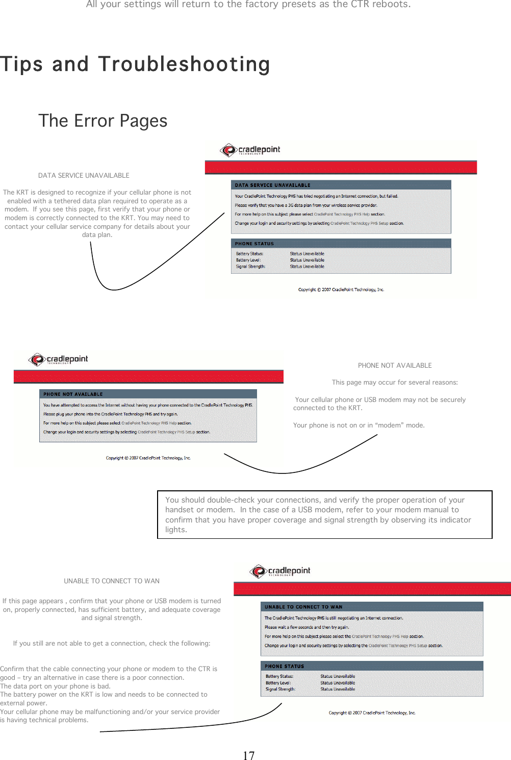
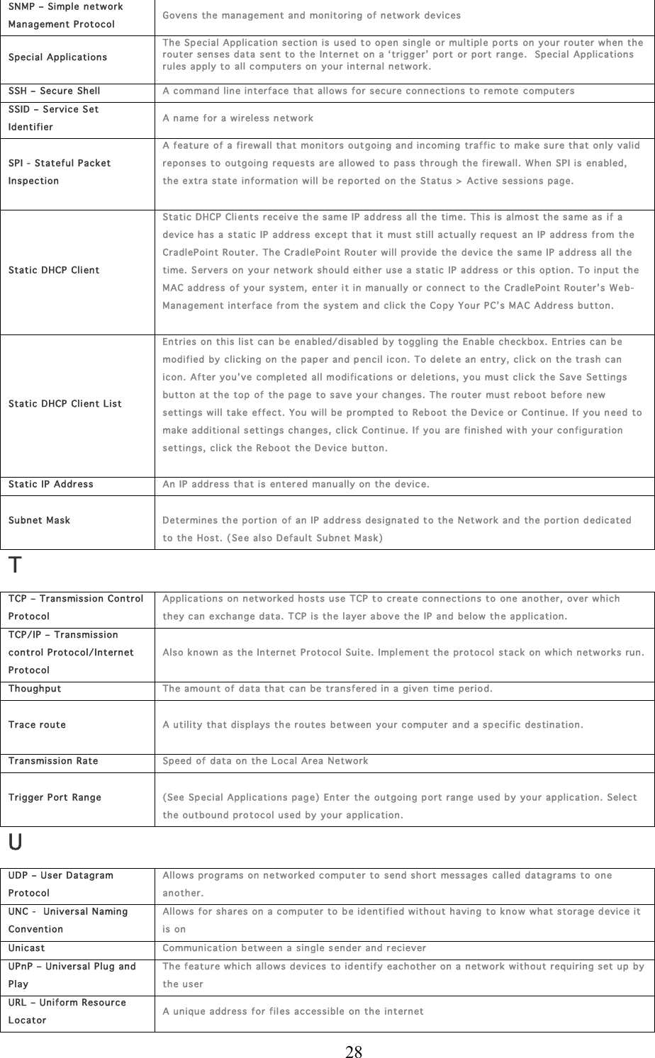
![29 V VPN – Virtu al Private Network A secure tunnel over th e internet to connect r emote offices or users to thier c ompany’s network Virtual Sever Th e Virtual Server op tion gives Int ernet users access to services on your L AN. This feature is useful for hostin g online services such as FTP, W eb, or Game Servers. For each Virtual Server, you define a public p ort on your r outer f or r edir ection t o an internal L AN IP Address and port. Example: You are hosting a Web Server on a Laptop or PC that has Private IP Address of 192.168.0. 50 and you r ISP is block ing Port 80. 1. Name the Vir tual Server Rule ( ex. Web Server) 2. En ter in the IP Addr ess of the machine on your LAN 19 2.1 68.1.1 3. En ter the Private Port as [80] 4. En ter the Public P ort as [8888] 5. Select th e Pr otocol - T CP 6. En sur e the schedule is s et t o Always 7. Chec k the Add Ru le to add the settings 8. Repeat these steps for each Virtu al 9. Server Rule you w ish to add. After the list is c omple te, c lick Save Se ttings at the top of th e page. With this Virtual Server Rule all Internet traffic on Port 88 88 will be red irected t o your inter nal web serv er on port 80 at IP Address 192.168.0.50. Virtual Servers List Entries on this list can be en abled/disabled b y toggling the Enable check box. Entries can b e modified by c licking on the paper and pencil icon. To del ete an entry, click on the trash can icon. After you’ ve compl eted all modif ications or deletions , you must click the Save Se ttings button at the top of the pa ge to save your changes. The router must reboot before n ew settings w ill take effect. You will be prompt ed to Reb oot the Devic e or Continue. Reb oot the device if you are satisfied w ith you r settin gs. Virtual Server Rule Name of the virtual s erver, such as W eb Server Visibility Statu s Whether or not the SSID will be visible on th e LAN. If this is set to invisible oth er s will not beable to see y our network in their list of availabl e networks withou t s pecial configurations. You will have to conn ect to an invisible n etwork by manually entering the na me into your con nect utility on you r computer. VoIP – Voice over Int ernet Protocol (IP) Sending voice information over the internet W Wake on L AN Allows you to power up a computer thrrough it’s NIC on a WAN. Web Browser A utility th at allows you to view content and interact with all of th e information in the Wor ld Wide Web. E xamples include: Firefox, Mozzilla, Safari, Opera, and lastly thou gh of ten less flexible and secure, Internet Explorer. WEP – Wir ed Equ ivalen t Privacy Security for wireless n etwor ks that is supposed t o b e c ompatible t o th a t of a wir ed network. Wi-Fi Wireles s Fidelity WPA – WiFi Protected Access An updated version of security for w ireless networks that provides authentication as well as encryption . Wide Area N etwor k A network s panning a lar ge geographical area or consisting of more than one L AN. Wireles s Network Name Th e SSID for the router. WISP - Wireles s ISP A company that provides a br oadband c onnection o ver w ireless c onnections to the internet.](https://usermanual.wiki/Cradlepoint/CTR350/User-Guide-754995-Page-30.png)