Cradlepoint CTR350 Cellular Travel Router User Manual CTR User s Manual
Cradlepoint, Inc. Cellular Travel Router CTR User s Manual
Users Manual
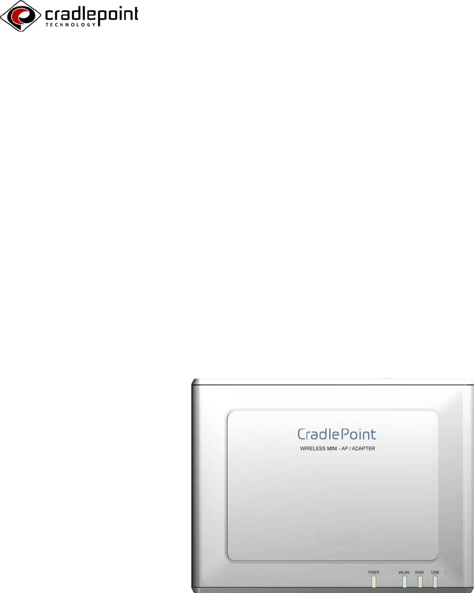
CTR Cellular Travel Router
User’s Manual
1
Contents
Getting Acquainted
2 Compliance Notes
3 Introduction
4 CTR at a Glance
5 Using the Controls
6 Getting on the Internet
Configuring Your Wi reless Network
7 Welcome to the Help and Setup Pages
8 Navigating the Help and Setup Pages
12 The Wizards
16 Factory Default Reset
Tips and Troubleshooting
17 The Error Pages
“Data Service Not Available”
“Phone Not Available”
“Unable to Connect to WAN”
18 “Handset Error”
“DNS Poisoning”
“Maximum Number of Users Connected”
19 Security Notes
20 Care and Maintenance
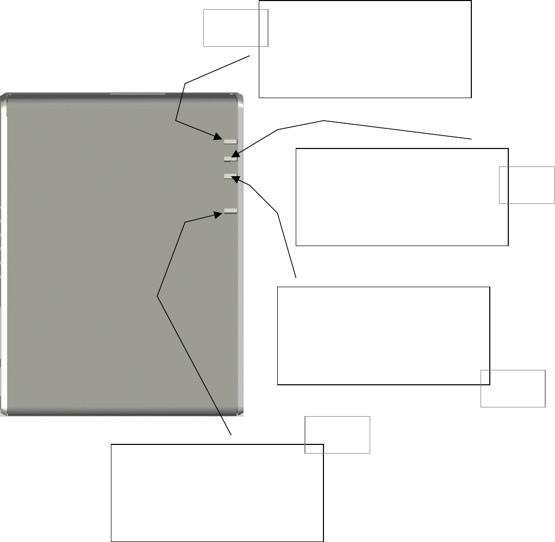
21 Indicators (LEDs)
22 Glossary and Setup Details
2
Compliance Notes
FCC No tice:
This device complies with part 15 of the FCC rules. Operation is subject to the following two conditions:
(1) This device
may
not cause harmful interference, and (2) this device must accept any interference
received, including interference that may cause undesired operation.
Caution:
The user is cautioned that changes or modifications not expressly approved by the party responsible for
compliance could void the warranty and users’ authority to operate the equipment.
Note:
This equipment has been tested and found to comply with the limits for a Class B digital device, pursuant
to part 15 of the FCC Rules. These limits are designed to provide reasonable protection against harmful
interference in a residential installation. This equipment generates, uses and can radiate radio frequency
energy and, if not installed and used in accordance with the instructions, may cause harmful interference
to radio communications. However, there is no guarantee that interference will not occur in a particular
installation. If this equipment does cause harmful interference to radio or television reception, which can be
determined by turning the equipment off and on, the user is encouraged to try to correct the interference
by one or more of the following measures:
• Reorient or relocate the receiving antenna.
• Increase the separation between the equipment and receiver.
• Connect the equipment into an outlet on a circuit different from that to which the receiver is connected.
• Consult the dealer or an experienced radio/TV technician for help.
IMPORTANT NOTE:
FCC Radiation Exposure Statement:
This equipment complies with FCC radiation exposure limits set forth for an uncontrolled environment. This
equipment should be installed and operated with minimum distance 20cm between the radiator & your
body.
Caution:
To comply with the FCC RF exposure compliance requirements, this device must not be co-located or
operating in conjunction with any other antenna or transmitter.
Industry Canada Notic e:
Operation is subject to the following two conditions: (1) this device may not cause interference, and (2)
this device must accept any interference, including interference that may cause undesired operation of the
device. The term “IC:” before the radio certification number only signifies that Industry Canada technical
specifications were met. This product meets the applicable Industry Canada technical specifications of the
RSS210.
This class B device complies with Canadian ICES-003.
Cet appareil numérique de la classe B est confome à la norme NMB-003 du Canada.
FCC COMPLIANCE STATEMENT
Property of CradlePoint, Inc For Internal Use Only.
Unauthorized reproduction and/or distribution is strictly prohibited.
This product is protected under copyright law and trade secret law
as an unpublished work.
Copyright (C) 2007 CradlePoint, Inc All rights reserved.
3
Introduction
WELCOME
The CradlePoint CTR (Cellular Travel Router) is a high-performance Bro adband Cellular Ga te way
designed to provide fast a nd convenient Internet access while connected to a Cellular modem o r
handset. The CTR provides a straightforward and portable Interne t connection leveragi ng advances
from C radlePoint Technologies, Inc. The CTR includes the following features:
Establishes shared network connection via standard WAN PPP when connecting DSL, Cable Modem, or other
uplink to Ethernet port
Establishes shared network connection via Cellular when connecting Cellular Phone or Cellular Modem to USB
port
Designed to work with all 3G cellular service provider networks
Supports up to 128-bit WEP and WPA encryption for data-security
Supports Virtual Private Network (VPN) pass-through
Supports 1 Wired LAN connection
Rugged but compact design is perfect for fixed or mobile applications
Software algorithms boost efficiency, performance, and improve perceived network speed
Auto-Upgrade Notification helps keep user updated with latest system CTR software revision
GUI-based device management from any standard web Browser
PACKA GE CONTENTS
CradlePoint CTR Cellular Travel Router
Power Adapter (5V/2.5A)
CD-ROM with Manual
Quick Installation Guide
Carrying Case
Note: Using a po wer supp ly wi th a different voltage t han t he one i ncluded w ith your product will ca use damag e and
void the warranty for thi s product.
If any of the above items are missing, please contact your reseller.
OVERVIEW OF FEATURES
Instantly creates a personal WiFi Hotspot anywhere within the Cellular Service Providers' network.
No software to install: Follows simplicity of 802. 11 wireless standards
Supports multiple simultaneous wireless LAN clients
Includes advanced wireless router features:
o NAT/NAPT Firewall
o DHCP Server
o Security - MAC Address Filtering or WPA or WEP Encryption
o Web-based Configuration and User Interface
Automatic firmware upgrades
Bridges from Cellular phone/modem connection to wired Ethernet for a no-software secure Internet connection
Recharges the handset battery and CTR internal battery when connected to an external power source.
Windows, Macintosh and Linux support.
4
A
B
B
C
D
D
E
F
G
H
I
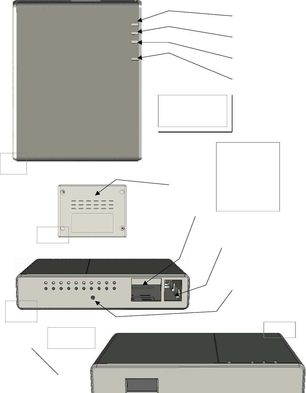
A. LED 0 - USB Status
B. LED 1 - LAN Status
C. LED 2 - WLAN Status
D. LED 3 - Power Status
E. Ventilation Slots
F. CAT 5 (Ethernet) Port
G. Power Connector
H. Factory Reset Button
I. USB Port
CTR at a Glance
Input / Output
Bottom
Rear
Front
Top

5
Using the Controls
A
LED 0 –
USB Status
Green
Connection to USB port is established.
OFF
USB port not in use.
B
LED 1 –
WAN Status
Green
Wide Area Network is ready via the Ethernet port.
OFF
Ethernet port not in use or the connection is not secure. Port not in use.
C
LED 2 –
WLAN Status
OFF
No handset connected, unit is negotiating the connection, or no WLAN available.
D
LED 3 –
Power Status
Green
CTR is connected to external power / on.
OFF
CTR is OFF.
E
Ventilation Slots
These allow excess heat to be removed from the CTR while operating. It is recommended that the unit not be
covered with any material that will block the dispersion of heat away from the unit. The unit should not reach
extreme temperatures.
F
Ethernet Port
The Ethernet port allows you to connect to the unit via CAT5 cable on a LAN.
G
ON / OFF Status
&
External Power
Connection
OFF
The unit is completely OFF when the unit is not connected to external power and the ON / OFF switch is in the
OFF position.
The unit will charge its own battery and the phone battery if switched OFF and connected to external power.
Note: The option to charge the phone’s battery must be selected in the CTR setup pages.
The unit will ONLY charge the phone battery when switched OFF and NOT connected to external power. Note:
The option to charge the phone’s battery must be selected in the CTR setup pages.
* No access to the router or the wireless network can be established while the unit is OFF.
ON
If the unit is ON and not connected to a phone or handset, it’s Setup / Help Pages are still accessible by
associating with its SSID (Network Name) and entering 192.168.0.1 into the URL bar of a web browser. Note:
Login will be required to access the CTR Setup / Help Pages
If the unit is ON and connected to a fully operable data-enabled cell phone or USB modem a wireless network will
be automatically established. The laptop will automatically associated with the network. In some cases the user
will need to selected the wireless network from their laptop’s wireless network list. (Details vary by Operating
System.)
The unit will operate off external power exclusively while connected to an external power source. If there is
sufficient excess power available the unit will also charge the phone.
The power connector is a standard jack size and when connected to the proper cable and an external power
source will power the CTR according to the specifications listed in the ON / OFF switch section of the Controls
list.
H
Factory Default Reset
Button
To return all the User Defined configurations (such as those specified in the Setup / Help Pages) to their original
factory default settings simply turn the unit OFF, press and hold the Factory Default Reset button, and turn the
unit ON. After the LEDs have flashed ON then OFF then ON again, release the button. All setting should be
reset.
I
USB-to-Modem Port
This is a standard USB port that is used to connect either to a USB modem or to a data-enabled cellular phone.
Cables for USB to Data connection vary by phone manufacturer and are not provided with the CTR. Contact your
service provider for further information.
CAUTION: Using a power supply with a different voltage than the one included with
your product will cause damage to the unit and void the warranty.

6
Getting Connected
The CTR supports two methods of connecting to the Internet: 1) a standard wired-WAN connection such as a DSL,
Cable, or Hotel Ethernet, or hosted LAN connection; or 2) a Cellular modem connection using either a data-enabled
handset or USB Modem. In the Wired-WAN case, connect the LAN cable into the Ethernet port of the CTR and it will
establishes a connection to the Internet. In the Cellular case, plug your USB modem or handset into the USB host port
and the CTR will establish a connection to the Internet.
The CTR unit will begin broadcasting signals to create a local Wireless LAN network. If using a cellular phone, be sure
you have configured the phone’s settings to act as a modem and have established a 'data plan' with your
carrier/operator. Note that even though you may have a "Data Plan" for Internet access on the phone, there may be a
separate option to enable 'tethered data'. If you do not have this option activated, you must contact your cellular
carrier to activate this service. From your PC, use the wireless network finder to associate with your new wireless
network. The first time you use the CTR your network will be named:
CTR-xxx
Where ‘xxx’ is the last three digits of the CTR’s 12 character MAC address (the MAC address is individualized and unique
to each unit). This MAC Address is printed on the bottom label of the CTR.
Once your computer has associated with your wireless network, open a standard Internet Browser application on your PC
and you will be prompted to enter a password. The default password is the last six (6) characters of the MAC address
(again, printed on the bottom of the unit). Once logged in, you will be presented with a 'successful logon' screen,
indicating you can begin access the Internet with any of your PC applications. If you want the CTR to automatically
recognize your PC, click the 'Remember Me' option, and your PC will be automatically logged in upon WLAN association.
It is recommended that you change your password after your first login, which is easily accomplished using the CTR
Setup Wizard.
So how does it all work?
The CradlePoint CTR is a 802.11b/g WiFi router that is also able to use a cellular phone–as-
modem. Regardless of the type of Internet Access you have – Wired-WAN, Wired LAN, or
Cellular, the CradlePoint CTR bridges from that Internet access to a local WiFi network. The
result is your own personal, portable wireless network or “hotspot”. Set it up anywhere
within your service provider’s coverage area whenever you want access to the Internet.
7
Configuring Your
Wireless Network
Welcome to the Help and Setup Pages!
To access the Help Pages / CTR Setup Pages:
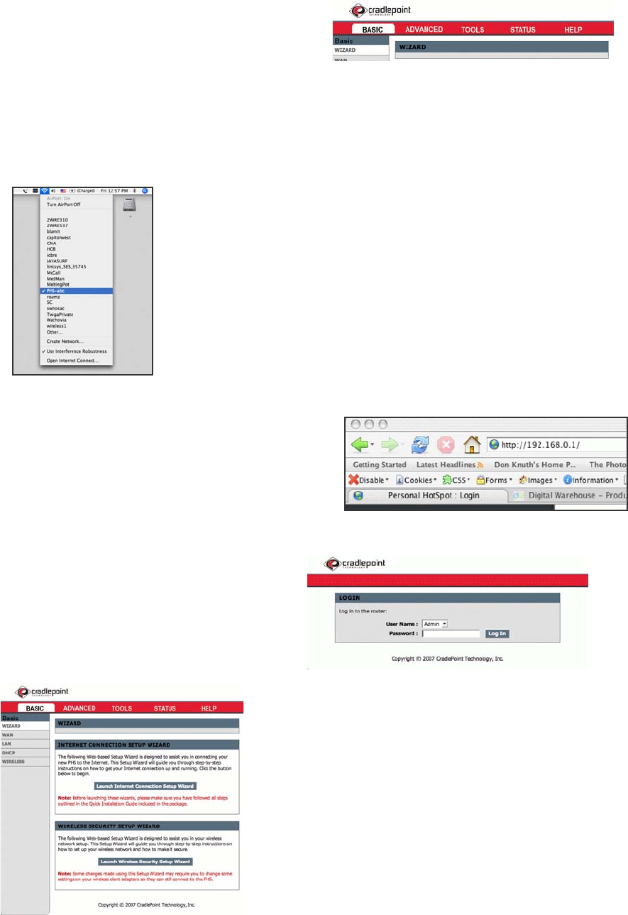
Be sure that the CTR and Phone/Modem are ON. Select the CTR-xxx wireless network from
your computer’s list of Wireless Networks.
Once your computer has associated with the CTR, open your
Web Browser and enter http://192.168.0.1 into the URL
Address bar. This allows you to access the CTR’s
embedded server pages.
You will be asked to enter your Password. The default
password is set to the last 6 digits of the CTR MAC Address
found on the bottom label of your CTR.
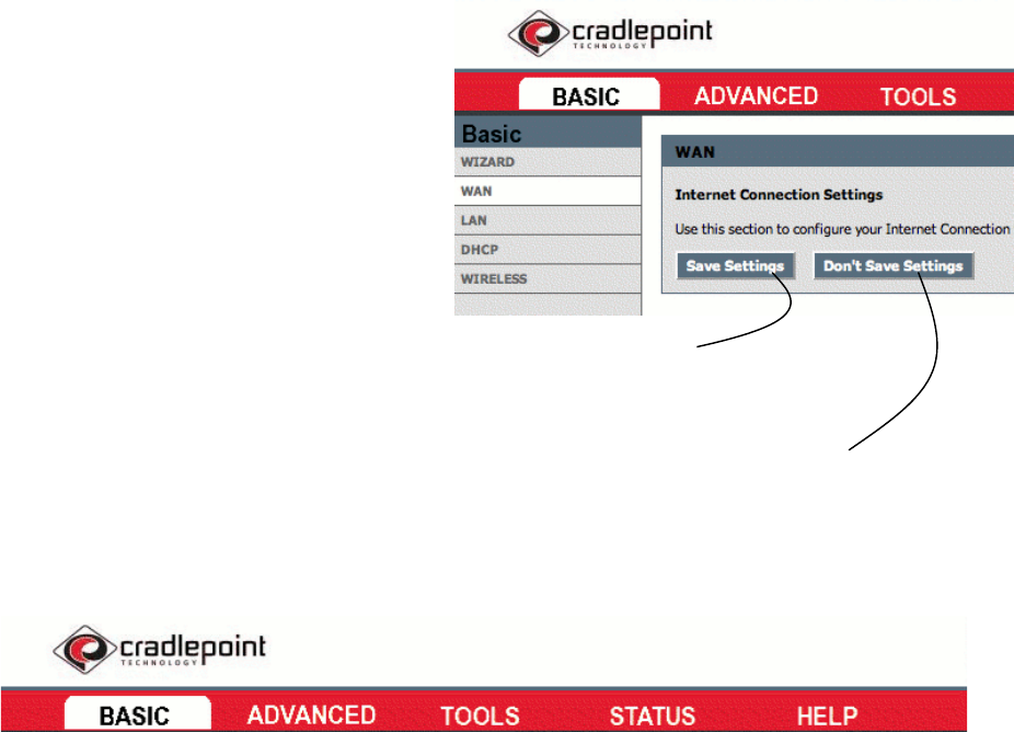
This is the home screen of the CTR Help and Setup Pages.
From here you can configure your network. It is recommended that you
run the Setup Wizard when you first use the CTR. This will allow you to
personalize your network name (SSID) and passwords, and you can change
the security settings to meet your needs.
8
Navigating the Help and Setup Pages
Select the Main Topic tab
you wish to use.
Use the side navigation menu to
access subtopics.
Be sure to save your settings
before leaving each page.
You can abandon all your changes at
anytime by selecting “Don’t Save Settings.”
What you’ll find in these pages
BASIC Topics
Wizard
These wizards are designed to assist you in
configuring your wireless network once you have
completed the steps found in the Getting On The
Internet section of this manual. Use the wizards
to name your network, set your new password,
and set the security levels for your new CTR.
Internet Connection Setup Wizard
Internet Security Setup Wizard
WAN
This page is used to set your Internet connection
type. For most users, the default settings are
appropriate for everyday usage.
Specify DNS Servers
Advanced DNS settings
MTU Settings
Link Drop Delay
WAN Port Speed
Ping Response Settings
MAC Cloning Settings
LAN
Use this page to configure the internal network
settings of your CTR router. The IP Address that is
configured here is the IP Address that you use to
access the Web-based management interface. If
you change the IP Address here, you may need to
adjust your PC’s network settings to access the
network again. The default settings are
appropriate for most everyday users.
Set IP Address
Set Subnet Mask
RIP Settings
Set Router Metric
Default Router set
Enable/Disable IGMP
Enable/Disable DNS Relay
DHCP
This page is used to configure the built in DHCP
Server to assign IP Addresses to the computers
on your network.
Enable/Disable DHCP Server
Specify DHCP IP Address Range
Specify Lease Time
Enable DHCP Broadcast
View DHCP Clients
Add DHCP Reservation
View Reservations List
Wireless
This page is used to configure your basic wireless
settings for your CTR. From here you can set the
visibility of your network to others, your wireless
Enable/Disable Wireless Radio
Set SSID
Set Network Visibility
Auto/Manual Channel Select

9
network name, and security type. Some of these
features may have already been set by you if you
used the Setup wizards on the main screen of the
Help and Setup Pages.
Set Transmission Rate
Set 802.11 Mode
Set “Super G “Mode
ADVANCED Topics
Virtual Server
The Virtual Server option allows you to define a
single public port on your router for redirection to
an internal LAN IP Address and Private LAN port if
required. This feature is useful for hosting online
services such as FTP or Web Servers.
Add Virtual Server
View Virtual Servers List
Special Applications
The Special Applications option is used to open
single or multiple ports on your router when the
router senses data sent to the Internet on a
“trigger” port or port range. Special Applications
rules apply to all computers on your internal
network.
Application Level Gateway (ALG) Configuration
Add Special Applications Rule
View Spec Applications Rules List
Routing
The Routing option allows you to apply fixed
routes to defined destinations.
Add Route
View Added Routes List
View Existing Routes List
Access Control
The Access Control option allows you to control
access in and out if your network. Use this feature
as Access Controls to only grant access to
approved sites, limit web access based on time or
dates, and/or block network access for certain
applications.
This page includes a wizard to assist you in adding
new policies.
Enable/Disable Access Control
Policy Wizard
View Existing Policies
Web Filter
The Web Filter option allows you to set up a list of
allowed Websites that can be used by multiple
users. When the Web Filter is enabled, all other
Websites not listed on this page will be blocked.
To use this feature, you must also select the
“Apply Web Filter” checkbox in the Access Control
Section.
Add Website(s)
View allowed Websites
MAC Address Filter
The MAC Address (Media Access Controller) filter
option is used to control network access based on
the MAC Address of the network adapter. This
feature can be used to ALLOW or DENY specific
machines on your network.
Enable MAC Address Filter
Filter Setting (Allow/Deny clients)
Add MAC Address
View Filters
Firewall
The DMZ (Demilitarized Zone) option provides you
with an option to set a single computer on your
network outside of the CTR router. If you have a
computer that cannot run Internet applications
successfully from behind the router, then you can
place the computer into the DMZ for unrestricted
internet access. This option is recommended to be
a last resort, as it tends to leave the DMZ
computer at a security risk.
Enable DMZ
Set the DMZ IP Address
Inbound Filter
The Inbound Filter option is an advanced method
of controlling data received from the Internet.
With this feature you can configure inbound data
filtering rules that control data based on an IP
address range. You can use this to limit access to
a server on your network to a system(s).
Add Inbound Filter Rule
View Added Inbound Filter Rules
Advanced Wireless
These are more advanced settings for your
wireless network. If you are unfamiliar with the
settings it is recommended that you read the help
section on this subtopic before changing any of
the presets.
Fragmentation Threshold
RTS Threshold
Beacon Period
DTIM Interval
Enable 802.11d
Transmit Power
WDS Enable
(Add WDS AP MAC Address)
Schedules
The Schedules Rules feature is used to manage
parental controls and firewall rules according to a
schedule you define.
Add Schedule Rule
View Added Schedule Rules

10
TOOLS Topics
Admin
The admin option is used to set a password for
access to the Web-based management. By default
there is not an Admin password (the default
password you are familiar with by now is the User
password).
Set Admin Password
Set User Password
Administration and Remote Settings
Enable / Disable UPnP
Save and Restore Configuration
Time
The Time configuration option allows you to
configure, update, and maintain the correct time.
From this section you can set the time zone that
you are in and set the NTP (Network Time Protocol)
Server. Daylight Savings can also be configured to
automatically adjust the time when needed.
Time zone and Daylight savings settings
Enable / Disable and set NTP Server
Set the date and time manually
Allows for you to copy your computer’s current
time settings.
Syslog
This option allows you to log information about your
network. You can send this information to a Syslog
Server.
Enable / Disable Syslog Server
Set Syslog Server IP Address
Email
The Email option can be used to send your Syslog
information to your e-mail account. You can also
select at what intervals you would like to receive
this information about your network.
Enable / Disable E-mail Notification
Set Email Settings
Set Email Notification Schedule
System
The System page allows you to reboot your CTR
router to the factory default settings without using
the hardware Reset button found just inside and
under the battery cover of the unit. Remember,
restoring the Default Factory Settings will erase all
of your configured changes.
Reboot the Device
Restore all Settings to the Factory Defaults
Firmware
The Firmware page allows you to check for and
install the latest version of your CTR software.
Upgrades improve the functionality and
performance of the CTR. You can set the CTR to
notify you by E-Mail when a newer version of the
software is available.
Firmware information and latest version check
Download Firmware Upgrade section
Set Firmware Upgrade notification options
Dynamic DNS
The DDNS feature allows you to host a server (Web,
FTP, etc) using a domain name that you have
purchased (www.yourchoiceofname.com) with your
dynamically assigned IP Address. Most Broadband
Internet Service Providers assign dynamic
(changing) IP Addresses. Using a DDNS service
provider, your friends can enter your host name to
connect to your server no matter what your IP
address is.
Enable / Disable DNS
Dynamic DNS Settings
11
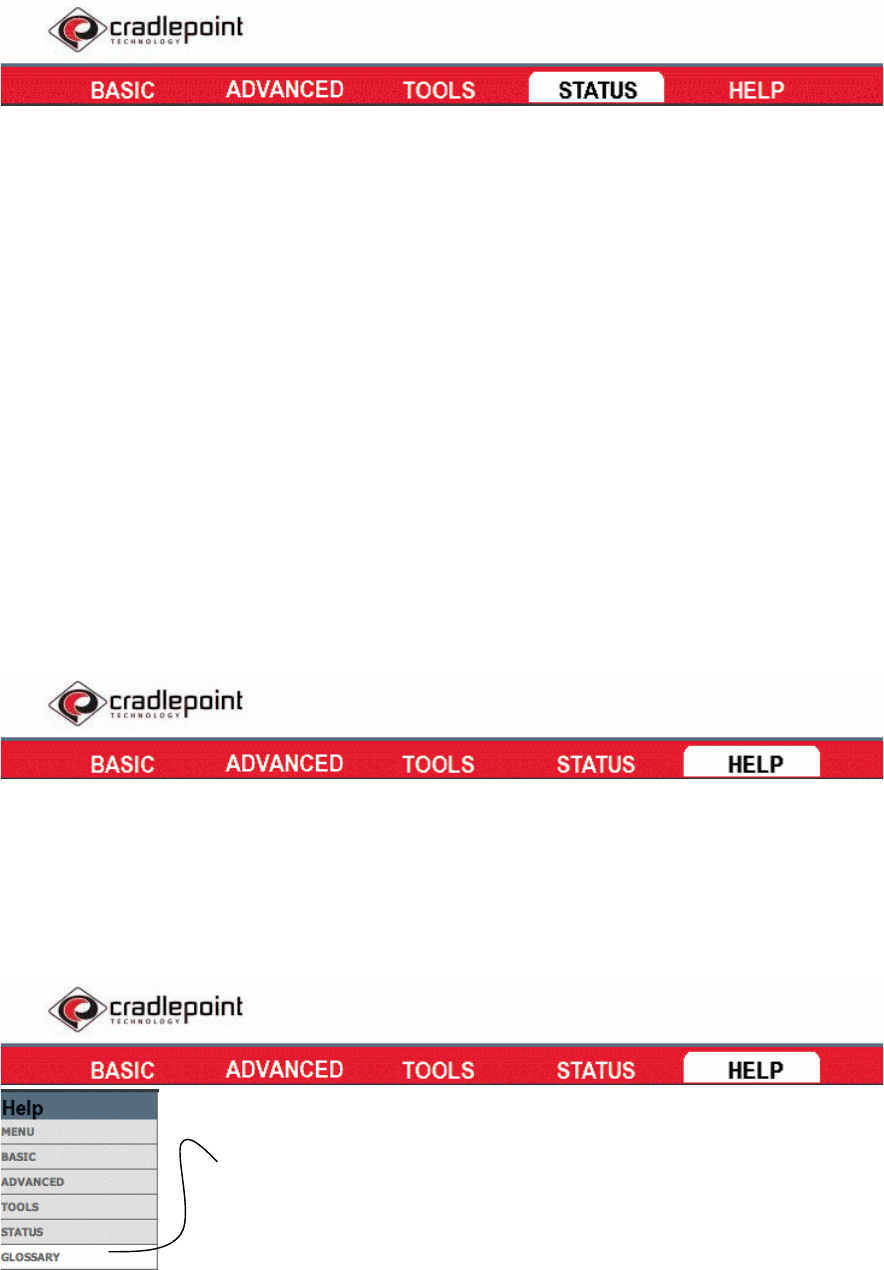
STATUS Topics
Device Info
All of your Internet and network connection details
are displayed on this page. The firmware version
is also displayed here.
View Time and Firmware Version
View WAN Settings
View LAN Settings
View Wireless LAN Settings
View LAN Computers
Wireless
Use this option to view the wireless clients that
are connected to your network.
View Number of Wireless Clients
View Trusted Clients
Routing
This page displays the routing details configured
for your CTR.
View Routing Settings
Logs
This page allows you to view the Syslog
information about your CTR. You can define what
types of events you want to view and the event
levels to view.
Set Syslog Options
View / Edit Syslog Details
Statistics
View all your network’s Traffic Statistics from this
page. Traffic Statistics display Receive and
Transmit packets passing though your CTR router.
LAN Statistics
WAN Statistics
Wireless Statistics
Active Sessions
This page displays the full details of the actives
sessions to your CTR router.
View Active Sessions
HELP Topics
Subtopics
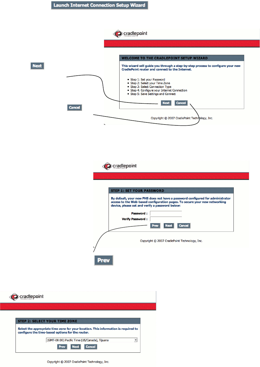
Each of the sections on the Help Topics page
contain a hyperlink for quick and easy location of
the subtopics you would like to view and/or edit.
Simply click the topic page in the side navigation
bar or click the subtopics in each section of the
page you would like to jump to.
Hyperlinks to each main and subtopic of the Help
and Setup Pages.
GLOSSARY Pages
The glossary provides you with definitions to aide your
understanding of the CTR functionality.
Hyperlinks by letter to jump to lexigraphically ordered
sections of the page.
12
The Wizards
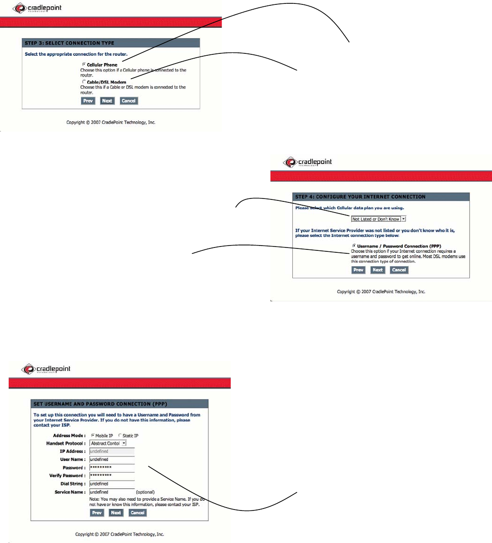
To begin, select on the main screen of the Help Pages.
Select to go to
the next step.
You can select at
anytime to return to the main
Help page.
When setting your password, it is more
secure to use a combination of letters
and numbers while using
something that is easy for you to
remember.
You can select at anytime to return to the previous step.
Select the arrow on the pull down menu
to show all available time zones and
chose the zone which applies to your
area.
13
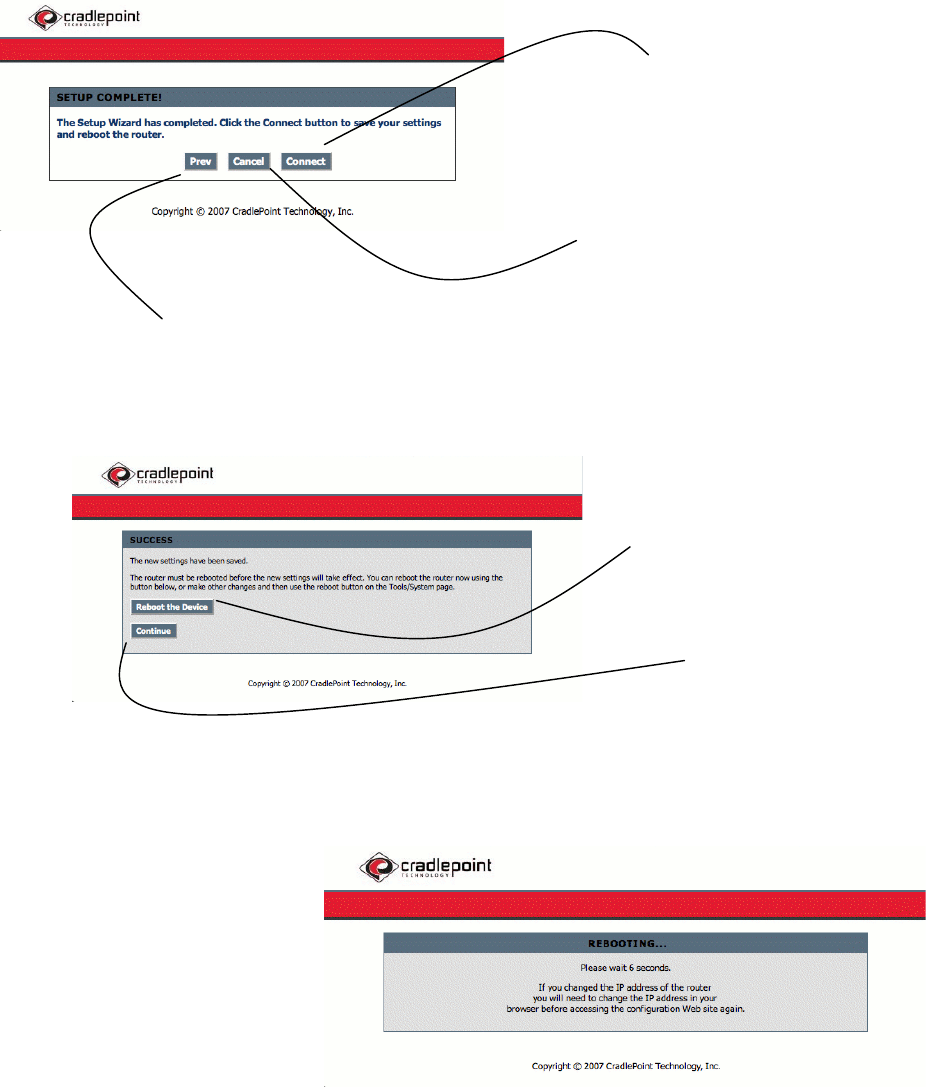
If you are using your cell phone or USB cellular modem.
If you are using Cable/DSL or other Ethernet LAN
connection over Ethernet to connect to the Internet.
Use the pull down menu to select your cellular plan.
Select if your network requires a password.
This information can be obtained by contacting your ISP
(Internet Service Provider). If you are using your cellular
phone, your ISP is your cellular operator such as Verizon,
Sprint, T-Mobile, etc.
14
Select when you are finished.
Abandon all changes and return
to the main Help Page.
Go Back.
Reboot the CTR to save and use your
changes now.
Continue without saving changes
until next reboot.
Allow a few moments for the
CTR to complete its reboot
cycle.
You will be asked to enter your
new password to login.
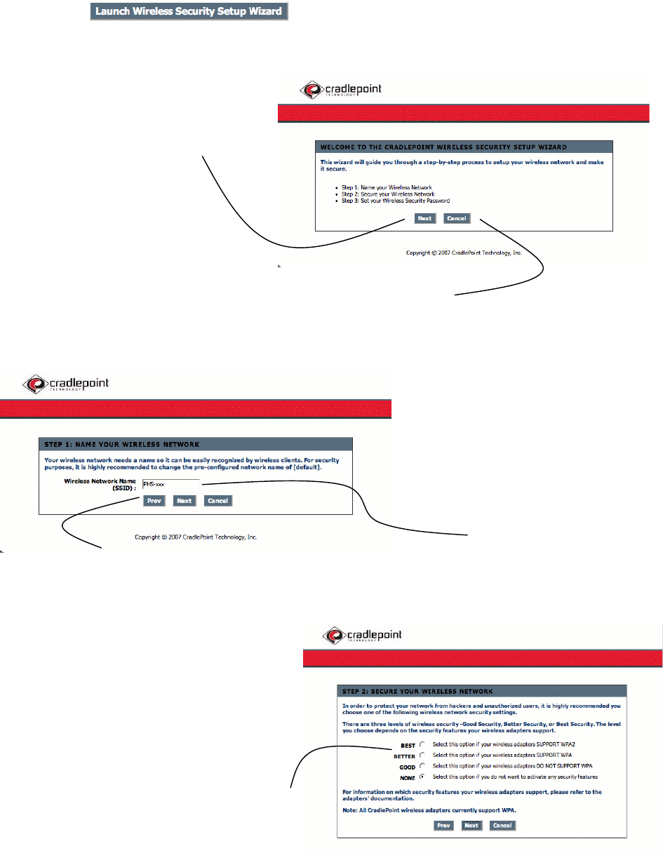
15
Your Basic Internet settings have now been configured!
After your changes have been saved, log into the CTR using your new password.
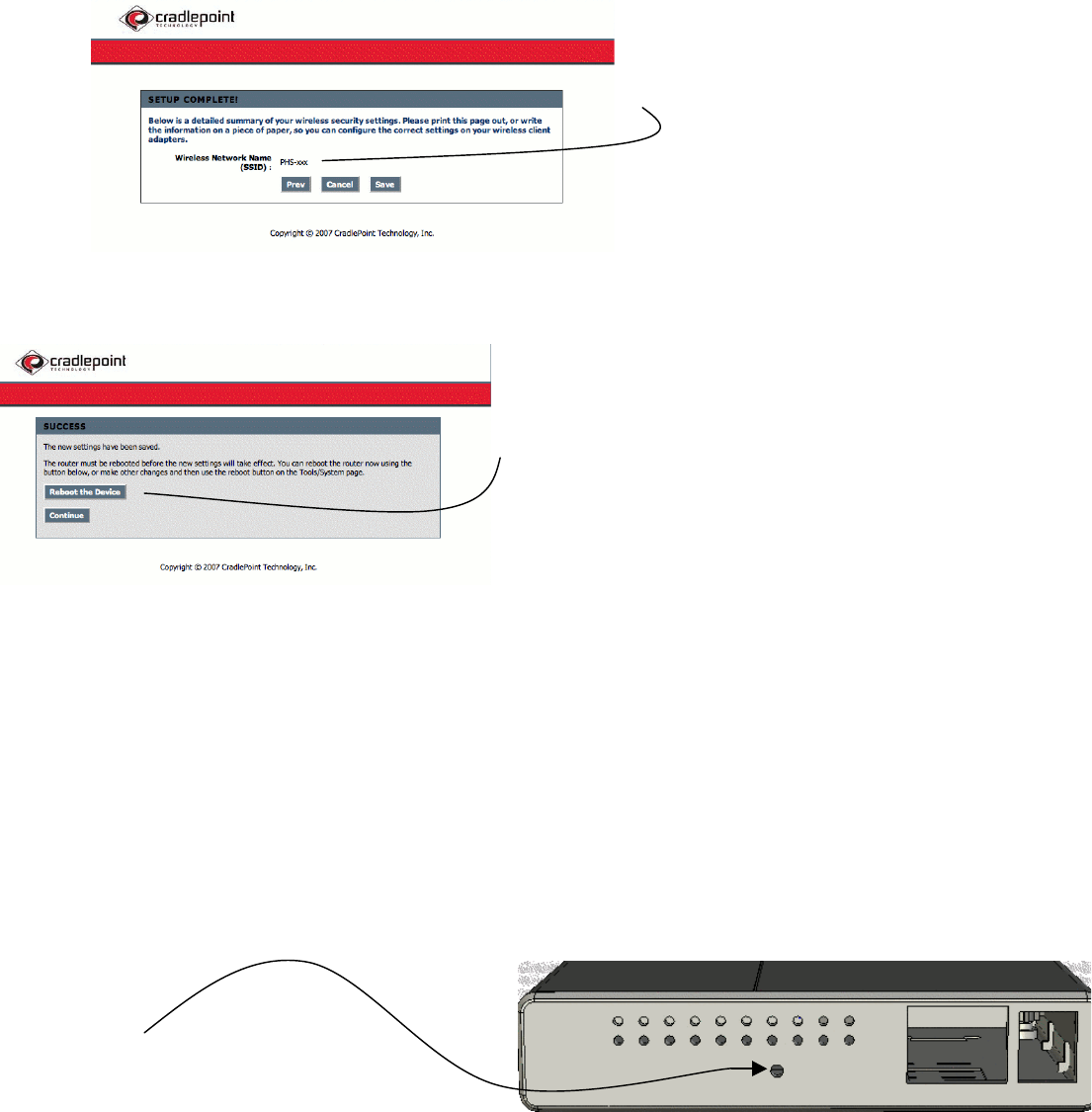
Select on the main screen of the Help and Setup page.
Select to go to
the next step.
Select to go back to the main screen
of the Help and Setup Pages at anytime.
This section will rename your wireless
network. It is the name others will see as
well the name shown in your list of available
wireless networks on your computer.
Go Back.
Security is an important aspect of your
online lifestyle. It is recommended that you
select “BETTER” or “BEST” to ensure
minimal attack from malicious Internet
users.
16
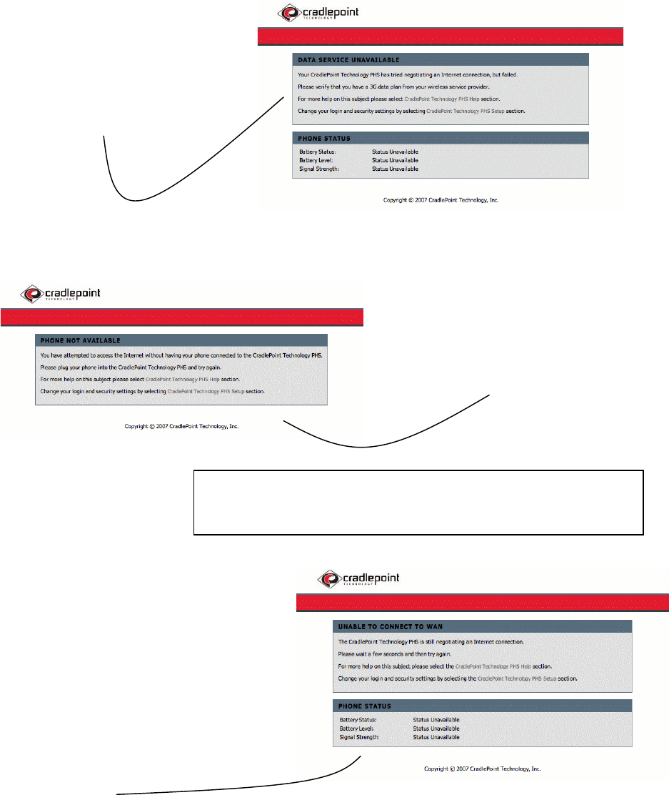
After you reboot your CTR be sure to look
for it by the new SSID. (Network Name)
Select Reboot the Device to save your changes. Allow a
few moments for your CTR to reboot and your computer
to re-associate with the network.
When you login you will be asked to enter you password according to your new security settings. If at
anytime you cannot remember your password you can reset the CTR to it’s factory default settings.
Factory Default Reset
The Factory Default reset will clear all your saved settings on the CTR. The user name and password will
revert back to the original “CTR-xxx” SSID and use the last 6 digits of the MAC Address for the password.
To use the factory default reset, simply:
1. Un-plug the CTR from external power.
2. Locate the Factory Reset button at the rear of the unit.
3. Press and hold the Reset button while you plug the CTR back into external power.
4. Release the button after you see the LEDs flash ON, OFF, then ON again.
17
All your settings will return to the factory presets as the CTR reboots.
Tips and Troubleshooting
The Error Pages
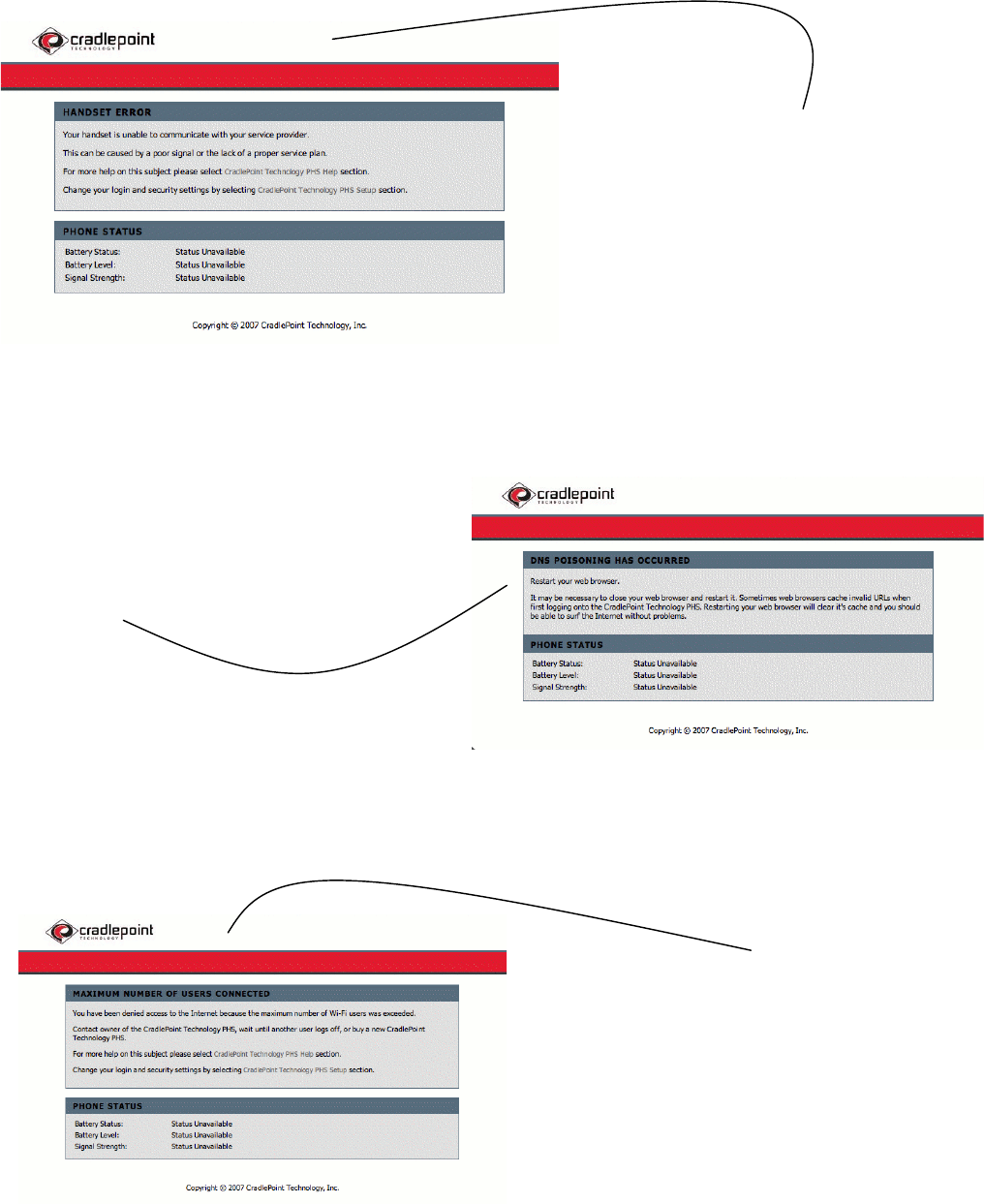
DATA SERVICE UNAVAILABLE
The KRT is designed to recognize if your cellular phone is not
enabled with a tethered data plan required to operate as a
modem. If you see this page, first verify that your phone or
modem is correctly connected to the KRT. You may need to
contact your cellular service company for details about your
data plan.
PHONE NOT AVAILABLE
This page may occur for several reasons:
Your cellular phone or USB modem may not be securely
connected to the KRT.
Your phone is not on or in “modem” mode.
UNABLE TO CONNECT TO WAN
If this page appears , confirm that your phone or USB modem is turned
on, properly connected, has sufficient battery, and adequate coverage
and signal strength.
If you still are not able to get a connection, check the following:
Confirm that the cable connecting your phone or modem to the CTR is
good – try an alternative in case there is a poor connection.
The data port on your phone is bad.
The battery power on the KRT is low and needs to be connected to
external power.
Your cellular phone may be malfunctioning and/or your service provider
is having technical problems.
You should double-check your connections, and verify the proper operation of your
handset or modem. In the case of a USB modem, refer to your modem manual to
confirm that you have proper coverage and signal strength by observing its indicator
lights.
18
HANDSET ERROR
If your phone has a bad signal, no service plan, a bad connection
port, a low battery, is OFF, or malfunctioning in some way, you
may get this page.
Try turning your phone OFF, then back ON or contact your service
provider for technical assistance. If you have been successful at
connecting before, try relocating the phone or modem to insure
you have proper coverage.
DNS POISONING
Occasionally after changing settings and rebooting the KRT the
browser’s cache needs to be cleared. If you see this page simply close
completely out of your browser and launch it again.
MAXIMUM NUMBER OF USERS CONNECTED
Appearance of this page indicates the number of users/clients allowed on
your network has been reached.
Either the maximum allowed clients setting is set too low or already at full
capacity.
The number of clients allowed on your network is a setting you can change
in the Help and Setup Pages on your KRT. The setting is by default only
set to 1 for your security and can be adjusted in the Help and Setup Pages.

19
Security Notes
It is highly recommended that you follow the next few suggestions to help ensure your security while using the KRT:
1. Change Admin Password
Changing the password to access your new router is the first step in securing your network. This can be done through the Wizard or on
the Admin Page of the Tools tab. Make sure that the password you choose is not commonly known or something that is easy to guess
such as your last name or your pet’s name. Try using a combination of letters and numbers (alpha-numeric) to deter intruders from
breaking into your network. Your private information should be kept private.
2. Disable DHCP and use Static IP addresses or Use Static DHCP and limit scope to the amount of users on your network.
The KRT comes with the setting for maximum users on your network set to 1. Until you change this setting you will be the only
computer allowed to access the network. Even so, in the event that an intruder manages to gain access to your network, having DHCP
enabled makes it easier for the intruder to access other computers on your network.
There are two methods to prevent this:
One way is to disable DHCP and use static IP addressing on all the devices connected to your network. This would mean that the intruder
would have to know what network your devices are on in order to access them. However, this would make it more difficult to share
access with new or occasional users.
The second way is to change the scope of the DHCP server to only include enough IP addresses (or IP range) for the devices in your
network. You can then use the Static DHCP feature of the router to assign an IP address to each device on your network. Static DHCP still
dynamically assigns an IP address to your network devices but only allows for those defined devices to obtain an IP address.
3. Change the default LAN IP address
Change the default LAN IP address from 192.168.0.1 to an alternate IP address. There are 3 ranges of IP addresses that have been
reserved for use on Private Networks.
10.0.0.0 - 10.255.255.255 (10.0.0.0/8)
172.16.0.0- 172.31.255.255 (172.16.0.0/12)
192.168.0.0 - 192.168.255.255 (192.168.0.0/16)
CradlePoint KRT routers use 192.168.0.1 as their default LAN IP address. Choosing an alternate IP address lessens the probability of an
intruders knowing what IP network your devices are on.
4. Set up MAC Filtering
Each networking device (router, network card, etc) on a network contains a unique hexadecimal number that identifies that specific
product. This number is referred to as a MAC address. MAC filtering allows you to create a list of the MAC address of each device on your
network and only allows these specific devices to associate with your network. With this feature enabled, devices attempting to connect
to your network with a MAC address that is not in the list you created, will be denied access.
THE KRT COMES TO YOU WITH YOUR SECURITY IN MIND:
The Personal HotSpot is equipped with several features designed to maintain security and provide easy setup to with any Cellular data network.
· PCs Hidden by NAT
NAT opens a temporary path to the Internet for requests originating from the local network. Requests originating from outside the LAN
are discarded, preventing users outside the LAN from finding and directly accessing the PCs on the LAN.
· IP Address Sharing by NAT
The Personal HotSpot allows several networked PCs to share an Internet account using only a single IP address, which may be statically
or dynamically assigned by your Internet service provider (ISP). This technique, known as NAT, allows the use of an inexpensive single-
user ISP account.
· Automatic Configuration of Attached PCs by DHCP
The Personal HotSpot dynamically assigns network configuration information, including IP, gateway, and domain name server (DNS)
addresses, to attached PCs on the LAN using the Dynamic Host Configuration Protocol (DHCP). This feature greatly simplifies
configuration of PCs on your local network.
· DNS Proxy
When DHCP is enabled and no DNS addresses are specified, the Personal HotSpot provides its own address as a DNS server to the
attached PCs. The Personal HotSpot obtains actual DNS addresses from the ISP during connection setup and forwards DNS requests
from the LAN.

20
Care and Maintenance
Operating Temper atures
Th e op erating temperatu res should re main between 0°C to +55°C degre es. Temperatu res ou tside
th is range may cause dama ge to your KRT.
Storage Temperatu res
Store your KRT in temp eratures not to exceed th e bounds of -40°C to +85°C. Temperatures
outside this range may cause damag e to your KRT.
Humidity
Exposure to humidity can cause your K RT to malfu nction and/or cause permanent damagg e. To
avoid this, keep your router at hu midity lev els betwe en 0 and 70%.
Shoc k and Vibration
Th e KRT may stop function ing if exposed to too much vibration or electrical shock. It is
rec omm en ded that you place the KRT out of areas that ma y introduce t h ese factors. Contact
th e manufacturer for specific details.
Network Range and
In terfer ance
Placing the KRT near metal cabinets or computer cases, large objects s u ch as refridgerators, or
around windows tinted w ith Metalic-based UV coatings can c ause interference. If you are
experiencing problems with the r ang e or interferenc e be sure that you r KRT is at least placed as
high as pos sible if it cannot be placed in the center of your preffer ed cover age area.
Stable Position
No Shock
Low Vibration
No Water
Mild
Temperature
°F/C°
21
COLOR
STATUS
Green
Connection to USB port is established.
Off
USB port not in use.
COLOR
STATUS
Green
Wide Area Network is ready via the Ethernet port.
Off
Ethernet port not in use or the connection is not
secure. Port not in use.
COLOR
STATUS
Green
WLAN is operating correctly.
Off
No handset connected, unit is negotiating the
connection, or no WLAN available.
COLOR
STATUS
Green
CTR is connected to external power / on.
Off
CTR is OFF.
Indicators (LEDs)
There are three dual LEDS used to display the device status and operation. The LED functions are identified below. The LED location and order are identified on
the PCB reference drawing. The normal operating states are described below. In addition, LED’s flash during power on, power off, reset and factory reset
functions to provide a visual feedback to the user of what is happening.
USB Status
(LED 0)
WAN Status
(LED 1)
WLAN Status
(LED 2)
Power Status
(LED 3)

22
Glossary and Setup Details
A
Access Control L ist
ACL. D atabase of network devices that are allow ed to access resourc es on the network.
Access Point
AP. D evice that allows wireless c lien ts to connect to it and access the network Ad-hoc n etwor k
- Peer-to-Peer n etwork betw een wireless clients
Address Res olution
Protocol
ARP. U sed to map MAC ad dresses t o IP addresses so that conversions c an be made in both
direc tions.
AD SL
Asymmetric Digital Subscriber Line
Advanced En cryption
Stan dard
AES. Government en cryption standard
Alphanumeric
Characters A-Z and 0-9
Antenn a
Used to transmit and rec eive RF signals.
AppleTalk
A set of Local Area Network protocols developed b y Apple for their compu ter systems
AppleTalk Addr es s
Resolution Protocol
AARP. Used t o map the MAC addresses of Apple computers to their AppleTalk network
addr esses, so that c on v ersions can be made in both directions.
Application layer
7th Layer of the OSI model. Provides s ervices to applications to en sur e that they can
communicate prop erly with other applications on a ne twork .
ASCII
Amer ican Standard Code for Information Interchange. This sys tem of ch arac ters is most
commonly u sed for t ext files
Attenuation
Th e loss in strength of digital an analog sign als. The loss is greater when the signal is b eing
transmitted o ver long distances .
Auth en tication
To provide cr ed entials, like a Password, in order to verify that the pers on or device is r eally
who they are claiming to b e
Automatic Pr ivate IP
Addressing
APIPA. An IP address th at a Windows computer will assign its elf when it is configured to obtain
an IP addr ess automatically but no DH CP ser ver is availabl e on the netw ork .
B
Backw ard Compati ble
Th e ability for n ew d evices to communicate and interact with older lega c y devic es to guarantee
inter operability
Bandwidth
Th e maxi mum amou nt of byt es or bits p er second that can be tran smitted to and from a
network devic e
Basic Input/Output System
BIOS. A program that the proc essor of a comput er uses to startu p the system on ce it is turned
on
Baud
Data transmission speed
Bit rate
Th e amount of bits that pass in giv en amount of ti me bit/sec – bits p er sec ond
BOOTP
Bootstrap Pr otocol. Allows for co mputers t o be boot ed up and giv en an IP address with no user
inter ven tion
Bottleneck
A time durin g processes when s om ething causes the proc ess to slowdown or stop all t ogeth er
Br oadband
A wide ban d of frequencies available for trans mitting data
Br oadcast
Tr ansmitting data in all dir ec tions at once
Br owser
A program that allows you to access r esour ces on the web and provides them to you graphically
C
Cable modem
A devic e that allows you to connect a computer up to a coaxial cable a n d r eceive Internet
access from your Cable provider
CardBus
A newer version of the PC Card or P CMCIA int erface. It supports a 32-bit data path, DMA, and
consumes less volta ge

23
Carrier Sense Multiple
Access/Collision Avoidance
CSMA/CA
Carrier Sense Multiple
Access/Collision D etect
CSMA/CD
CAT 5
Category 5. Used f or 10/100 Mbps or 1Gbps Eth ernet connections
Channel
Th e ch annel the w ireles s signal is transmitted on.
Client
A program or user that requests data from a serv er.
Collision
When do two devic es on the s a me Ethernet network try and transmit da ta at the e xact same
time.
Cookie
In formation th at is stor ed on the hard dr ive of your c omputer that hold s your pref er ences to
th e site that gav e your comput er the co okie.
Cracker
A talen t ed and malicious c omputer user w ho gain s unauthorized access to a c omputer or
network of computers with the inten tion of stealin g, malic iously modifying, or des troying
information. Also kn own as a “Black Hat Hacker.” Of ten mistak en ly refer red to as a Hacker.
CSMA/CA
Carrier Sense Multiple Ac cess/ Collision Av oidance C SMA/CD – Carrier Sense Multiple
Access/Collision D etection
D
Data
In formation th at has been trans lated into binary do that i t can be proces sed or move d to
another device
Data En cryption Standard
Uses a randomly selected 56-bit key that must be known by both the sender and the r ec eiver
when infor mation is exchanged
Data-Link layer
Th e second lay er of the OSI model. Controls the movement of data on the ph ys ical link of a
network
Database
Organizes information so that it can be managed updated, as w ell as easily accessed by users
or applications
DB-25
A 25 ping male conn ec tor f or attachin g External modems or R S-232 serial devices D B-9 – A 9
pin connector for RS-232 connections
dBd, dBi, dBm
decibels r elated to dipole antenn a, dec ibels relativ e to isotr opic radiator, decibels r elative to
one milliwatt
Decrypt
To unscramble an encrypted message back into plain tex t
Default
A predetermined value or s etting that is used by a program when no user input h as been
entered for this value or setting
Default Subnet Mask
Th e subn et on your r outer on the local area network
Demilitarized zone - DMZ
A single co mputer or group of computers that can be accessed by both users on the Internet as
well as u sers on th e Local N etwor k, but that is not protected by the sa me s ecu rity as the Local
Network.
DHCP
Dynamic Host C on figuration Protocol. Used to automatically assign I P a ddresses from a
pr edefined pool of addresses to computers or devices that r equests them (See Also D HCP IP
Address Range, Number of DHCP Dynamic Clients, Static DHCP Clients, DHCP L ease Time)
DHCP IP Address Range
Th is option defines the r ange of ad dresses available for the r outer to as sign to your internal
network If you h ave any devices using Static IP addresses, be sure the a ddresses do not fall
with in the range d efined her e.
DHCP L ease Ti me
Th e amount of time a computer may have an IP address b efor e it is r eq u ired to r en ew the lease.
Th e lease function s just as the lease on an apartment wou ld. Th e initial lease designates the
amoun t of ti me befor e the lease expires. If the t enant wishes to retain their address when the
lease is expire d th en th e lease is established. If the lease is no longer needed then the address
is allow ed to b e r eu sed by someone else.
Digital cer tificate
An elec tronic m ethod of providing credentials to a server in order to h ave access to it or a
network

24
Direct Sequence Spread
Spectrum – DSSS
Modu lation techniqu e used by 802.11 b wireless devices
Domain Name Syste m –
DNS
Tr anslates Domain Names to IP addr esses
Data Over Cable Service
In terface Specifications –
DOCSIS
Th e standard inter face for cabl e mode ms
Domain name
A name that is ass oc iated with an IP address
Download
To send a r equest from on e computer to another and have the file trans mitted back to the
requesting computer
DSL – Digital Su bscriber
Line
High badnwidth inter net con nection over telephone lines
Duplex
Sending and recieving data at the s ame time
DDNS – Dynamic DN S
service
Is provided n t com panies to allow users with Dynamic IP Addresses to obtain a Domain Name
th at w ill always be linked to th eir changin g IP Address. The IP Address i s updated either by
client sof tware or b y a rou t er that su ppor ts D DNS, w henever the IP Add r ess c han ges
Dynamic IP Address
IP address that is assigned b y a DHCP server and th at may chan ge. Cabl e Internet providers
usually use this method to assign IP Addr esses to their customer s
E
EAP
Extensible Authentication Protocol
Email
Electronic M ail is a c omputer-stored message that is trans mitted over t h e Internet
Encryption
Converting data into cyphertext so that it c ann ot b e easily r ead
Ethernet
Th e most widely used t echnology f or Local Area N etworks
F
Fiber optic
A way of s en ding data thr ough light impulses over glas s or plas tic wire or f iber
File server
A compu t er on a network that s tores data so that the other computers on the network c an all
access it
File sh aring
Allowing data from computers on a networ k to b e accessed by other computers on th e network
will different lev els of access rights
Firewall
A devic e that protec ts r esou rces of th e Local Area Netw ork from unauthorized users outside of
th e local network
Firmware
Programming that is insert ed into a hardw are device that tells it how to function Fragmentation
– Breaking up data into smaller piec es to make it easier to store
FTP – File Tran sfer Protocol
Easiest way to tran sfer files betw een c omputers on the Internet Full-duplex – Sen ding and
Receiving data at the same ti me
G
Gain
Th e amount an amplifier boosts the w ireless signal
Gatew ay
A devic e that connec ts your networ k to anoth er , like the your computer to th e internet
Gbps – Giga bits per second
Gigabit Ethernet
Tr ansmiss ion tech nology that transfers data at a rate of 1 billion bits per second
GUI – Graphical U ser
In terface
A visual w ay of interacting w ith a comput er using s uch items as w indow s, icons , and menu s.
Graphic al user interfaces are used by most modern operating sys tems
H
H.323
A standard that provides c onsistancy of voice and video transmission s and compatibility for
video con frencing de vices
Hacker
An enthu siastic and skillfull computer programmer or u ser c o mmonly mistak en by th e m edia for
a Cracker or Sc ript K iddie. (See Cr ack er)

25
Half D uplex
Data cannot be transmitted and r ecieved at the same time
Hashing
Tr ansforming a string of ch aracters into a shorter str ing with a predefin ed length
Hexid ecimal
Characters 0- 9 and A-F used to repr esent numbers also k nown as base 16
HomePNA, HomePNF
Networking over t elephone lines, Networking standard that combines 802.11b and DECT(Digital
enhanced cordless comminication) that provides s peeds up t o 1.6 m ega bits per s econ d and a
distance of 150ft using a Frequen cy Hoping transmission method
Hop
Th e action of data packets being tran smitted fro m one to another Host Computer on the
network
HTTP – Hypertext Transfer
Protocol
Used to transfer files from HTTP servers (web servers) to HTTP clients (web browsers)
HTTPS – Hypertext
Tr ansfer P rotocol over SSL
Used to encrypt and decrypt HTTP tran smissions , also know n as Seccure HTTP
Hub
A networking device th at c onnects multiple d evices togeth er
I
ICMP – Internet Control
Message Pr otocol
One of the core protoc ols of the Inter net protocol suite. Used mainly b y a networked
computers’ operating system to send er ror messages for IP datagrams , diagnostics, or r outing
pu rposes
IGMP – Internet Group
Managment Protoc ol
Used to make sure that computers can report their multicast group me mbersh ip to adjacent
router s
IIS – Internet Infor mati on
Server
A Web server and FTP ser ver provid ed b y M icrosoft
IK E – Inter net K ey
Exchange
Used to ensure s ecurity for VP N exch ange
In frastruc ture
In terms of a wireless n etwork this is w hen wirek ess c lien ts use an accress poin t t o fain acceess
to the networ k
In put Port Range
(See Special Application s page) The port range that you want to open t o inter net traffic
In terface
(See Rou ting page ) Specifies the n ex t hop to be taken if the route sp ecified is u sed. Agateway
of 0.0.0.0 implies ther e is no next hop and th e IP address match ed is c onn ected direc tly to the
router on the interfac e specified ( either LAN or WAN)
In ternet
A system of w orldwide netw orks which uses TCP/IP to allow for resources to be accr essed from
computers arou nd the wor ld
In ternet Explorer
One of many we b brows ers available for computers. Se e also M ozzilla. Fir efox, Konqurer, Opera,
Safari
In ternet Pr otocol
Th e method of tr ansfer ing data from one c omputer to an other on the In ternet
ISP – Internet Service
Procvider
Company that provides internet to individuals or companies
In teroperability
Th e ablity for products to interact with eachother without much c onsumer interaction.
Generally seen as an asset to any pr oduct
In tranet
A private n etwork
In tusion D etection
A typ e of security that s cans a n etwork to detect attacks coming f rom inside and outside the
network
IP – Internet Protocol
IP Address
A 32-bit number, w hen talking about Itern et Protocol Version 4, that id en tifies each computer
th at transmits data on the internet or intranet
IP v6 – Intern et Protocol
Version 6
Uses 1 28 bit addresses and was develop ed t o solve the pr oblem that we face running out of IP
version 4 addresses
IP X – Inter netwok Packet
Exchange
A networking protocol d eveloped b y Nov ell to enable th eir Netware clie nts and servers to
communicate
J
Java
A programming lan gu age used to cr eate progra ms and applets for web pages
K

26
Kbps
Kilobits per s econd
Ker beros
A method of securing and authenticating requests for services on a n et wor k
L
LAN – L ocal Area N etwork
A groupp of computers in a building that usually access files from a ser ver
Latancy
Th e amount of time a pack et takes t o travel from on e location to another on a network. Also
reffer ed t o as d elay.
LED
Light Em mitting Diod e
Legac y
Older d evices or technology
M
MB – MegaByte
Mbps
Megabits per s econd
MAC Addr ess
A unique hardware address for d evic es on a LAN. Each n etworking device (router, n etw ork car d,
etc) on a n etwor k contains a uniqu e hexadec imal n umber that id en tifies that specific product.
MAC Filtering
MAC filtering allows you to create a lis t of the M AC address of each dev ice on y our network and
only allows thes e specific devic es to assoc iate with your n etwork. With th is feature enabl ed,
devices attem pting to connec t to your n etw ork with a M AC address that is not in the list you
created, w ill be denied access.
Metric
(See Rou ting page ) Specifies the inter face, LAN or WAN, that the IP Packet must use to transit
out of the r outer w hen the selected route is used
MIB - Managem ent
In fomation Bas e
A set of objects that can be managed by us ing SNMP
MTU – M aximu m
Tr ansmiss ion Unit
Th e largest packet that can be transmitt ed on a packet based n etwork like the internet
Multicast
Sending data fro m one device to many devices on th e ne twork
N
NAT – Network Address
Tr anslation
Allows many private IP addr essses to connec t to the Internet, or anoth ernetwork, through one
IP address
NetBEUI
NetBIOS E xtende d U ser In t erfaceis a L ocal Area Network commincation protocol. Th is is an
updated v ersion of N etBIOS
NetBIOS
Network Basic In put/Output System
NetMask
Determines what portion of an IP ad dress desi gn ates the Network and w hic h art design ates the
Host
NetWare
Server software dev eloped by No vell
NIC – Netw ork Interface
Card
A card installed in a computer or built onto the m otherboard that allow s the computer to
connect to a network
Network Layer
Th e third layer of the OSI model which handles the routing of traffic on the network.
Number of Dynamic DHCP
Clients
In this sec tion, you can see what LAN devices are currently leasing IP addresses. The DHCP
Client tabl e displa ys the n umber of clients that are receiving an IP addr ess from th e router. The
computer nam e, MAC ad dress, and IP addr ess assigned to each computer are displaye d h ere as
well. You can Rev oke IP addr esses in this secti on. The revok e option allows you to take away a
leased IP ad dres s from a client. This feature is u seful for freeing u p add r esses w hen the clien t
table is f ull or nearly full. Be sure to only revoke ad dresses from device s th at are no longer
needed on the n etwork.
NTP – N etwork Time
Protocol
Used to s yn chr onize the time of all the comput er s on the network
O

27
OSI – Open Systems
In tercommun ication
Th e referen ce model for how data should travel b etw een two devices on a network .
OSPF – Open Short est P ath
First
A routin g protocol that is used mor e than RIP in larg er scale n etworks because only c han ges to
th e routin g tabl e are sent to all the o ther routers in the n etwork as opp osed to sending the
entire routin g table at a regu lar interval, w hich is how RIP functions.
P
Passs word
A sequence of ch aracters that is used to authenticate reques ts to resources on a network
Per sonal Area N etwork
Th e intercon nection of n etworking d evices w ithin a range of 10 meter s
Physical L ayer
Th e first layer of the OSI model, pro viding the h ardware a means of tran mittin g elec trical
sign als on a data c arrier
PoE – Power over Ether net
Th e means of transmitting electricity over the un used pairs in a C AT5 cable.
Policy N ame
(See Access Con tol page) The name of the acces control policy you hav e or are creating.
POP 3 – Post Office
Protocol 3
Used for recieving mail
PPP – Point to P oint
Protocol
Used for two compu ter s to comminicate w ith eachother over a serial interface, like a phone line
Preamble
Used to s yn chr onize c ommun ication timing between d evices on a networ k
Private P ort
Th e port th at will be used on your internal network
Public Port
Th e port th at will be accessed fro m th e internet
Q
QOS
Quality of Service
R
RADIUS – Remote
Auth en tication Dial-in U ser
Service
Allows for r emote users to dial into a c entral server and be auth en ticated in order to access
resou rces on a netw ork.
Remo te Managment
Allows you to manage your router from anywhere with an internet con n ection. See Tools
Admin
Remo te Management Port
Th e port th at will be accessed fro m th e internet.
Rendezvou s
Apple’s ver sion of UpnP, which allows f or devices on a network to discover eachother and be
connected w ithout the n eed to configu re any settings.
Repeater
Retransmits the signal of an Access Point in order t o extend its cover age.
RIP – Routing Information
Protocol
Used to s yn chr onize the routin g table of all the r outer s on a n etwor k.
RIP Ann ouncement
Th is option is u sed with multiple routers to broadcast r outing information.
Router Metr ic
Th is option is u sed if you have multiple r out er s.
RJ-1 1, RJ- 45
Th e most com mon ly used connec tion method for tel ephones, The most commonly use d
connection method for Eth ernet.
RS-232C
Th e interface for serial commu nic ation between c ompuuter s and oth er r ealated devices.
RSA Algorithm
Used for encryption and authentication.
S
Samba
A freew are program that allows for resour ces to be shared on a network. Mainly used in Unix
based op erating systems
Server
A compu t er on a network that provides services and resourc es to other computers on th e
network
Session K ey
An Encryption and d ecryption key that is generat ed for ev ery commun ication session between
tw o c omputers
Session L ayer
The fifth lay er of the OSI model w hich coordinates the con nection and commu nication between
applications at both ends
SMTP – Simpl e Mail
Tr ansfer P rotocol
Used for sending and recieving mail

28
SNMP – Simple n etwor k
Management Protocol
Govens the managemen t and monitoring of network devices
Special Applications
Th e Sp ecial Application sec tion is used t o open single or multiple ports on your r outer w hen the
router senses data sent to the Internet on a ‘trigg er’ port or port range. Spec ial Applications
rules apply to all computers on your internal network.
SSH – Secure Shell
A command line interface that allow s for secure connection s to re mote computers
SSID – Service Set
Identifier
A name for a wir eless network
SPI - Stateful Packet
In spec tion
A feature of a firewall th at monitors out going and incoming traffic to make s ure that on ly valid
reponses to ou tgoin g requests ar e allowed to pass through the firewall. When SPI is en abled,
th e extra state information will b e reported on the Status > Active sessions page.
Static DHCP Client
Static DHCP Clients receive th e same IP address all the time. This is almost the sa me as if a
device h as a static IP address exce pt that it must still actually request an IP addres s from the
CradlePoint Router. The CradlePoint Router w ill provide the devic e the same IP a ddress all th e
time. Servers on your network should eith er use a static IP address or this option . To input the
MAC address of your system, enter it in manually or c onnect to the Cr adleP oint Rou ter’s Web-
Management int erface from the syst em and clic k the Copy Your PC’s MAC Address button.
Static DHCP Client L ist
Entries on this list can be en abled/disabled b y toggling the Enable check box. Entries can b e
modified by c licking on the paper and pencil icon. To del ete an entry, click on the trash can
icon. After you’ ve compl eted all modif ications or deletions , you must click the Save Se ttings
button at the top of the pa ge to save your changes. The router must reboot before n ew
settings w ill take effect. You will be prompt ed to Reb oot the Devic e or Continue. If you n eed to
make additional s ettings changes, click Continue. If you are finished with your configur ation
settings, click the Reboot the De vice button.
Static IP Addr ess
An IP address that is enter ed manu ally on the devic e.
Subn et Mask
Determines the portion of an IP address designated to the Network and the portion d edicated
to the Host. ( Se e also D efault Subnet Mas k)
T
TCP – Transmission Con trol
Protocol
Applications on netw orked hosts use TCP t o creat e connec tions to one another, over which
th ey can exc hange data. TCP is the layer a bov e the IP and below th e application.
TCP/ IP – Transmission
control Protocol/ Inter net
Protocol
Also known as the Internet P rotocol Su ite. Implement the protocol stack on w hic h network s run.
Th oughput
Th e amount of data that can be transfer ed in a given time period.
Tr ace r oute
A utility th at dis plays th e routes between your c omputer and a spec ific destination.
Tr ansmiss ion Rate
Speed of data on th e Local Area N etwork
Tr igger Port Range
(See Special Application s page) Enter the outgoing port range used by your application. Selec t
th e outbound pro tocol u sed by your application.
U
UDP – User Datagram
Protocol
Allows programs on ne tworked computer to send short messages called datagrams to one
another.
UNC - Universal Naming
Convention
Allows for s hares on a computer to b e identified without h aving to kn ow what storage device it
is on
Unicast
Communication b etween a single sender and r eciever
UPnP – Universal Plug and
Play
Th e feature which allows devices to id entify each other on a network without requiring set up by
th e user
URL – U niform Resource
Locator
A unique address for fil es accessible on the internet

29
V
VPN – Virtu al Private
Network
A secure tunnel over th e internet to connect r emote offices or users to thier c ompany’s
network
Virtual Sever
Th e Virtual Server op tion gives Int ernet users access to services on your L AN. This feature is
useful for hostin g online services such as FTP, W eb, or Game Servers. For each Virtual Server,
you define a public p ort on your r outer f or r edir ection t o an internal L AN IP Address and port.
Example: You are hosting a Web Server on a Laptop or PC that has Private IP Address of
192.168.0. 50 and you r ISP is block ing Port 80.
1. Name the Vir tual Server Rule ( ex. Web
Server)
2. En ter in the IP Addr ess of the machine
on your LAN 19 2.1 68.1.1
3. En ter the Private Port as [80]
4. En ter the Public P ort as [8888]
5. Select th e Pr otocol - T CP
6. En sur e the schedule is s et t o Always
7. Chec k the Add Ru le to add the settings
8. Repeat these steps for each Virtu al
9. Server Rule you w ish to add. After the
list is c omple te, c lick Save Se ttings at
the top of th e page.
With this Virtual Server Rule all Internet traffic on Port 88 88 will be red irected t o your inter nal
web serv er on port 80 at IP Address 192.168.0.50.
Virtual Servers List
Entries on this list can be en abled/disabled b y toggling the Enable check box. Entries can b e
modified by c licking on the paper and pencil icon. To del ete an entry, click on the trash can
icon. After you’ ve compl eted all modif ications or deletions , you must click the Save Se ttings
button at the top of the pa ge to save your changes. The router must reboot before n ew
settings w ill take effect. You will be prompt ed to Reb oot the Devic e or Continue. Reb oot the
device if you are satisfied w ith you r settin gs.
Virtual Server Rule
Name of the virtual s erver, such as W eb Server
Visibility Statu s
Whether or not the SSID will be visible on th e LAN. If this is set to invisible oth er s will not
beable to see y our network in their list of availabl e networks withou t s pecial configurations. You
will have to conn ect to an invisible n etwork by manually entering the na me into your con nect
utility on you r computer.
VoIP – Voice over Int ernet
Protocol (IP)
Sending voice information over the internet
W
Wake on L AN
Allows you to power up a computer thrrough it’s NIC on a WAN.
Web Browser
A utility th at allows you to view content and interact with all of th e information in the Wor ld
Wide Web. E xamples include: Firefox, Mozzilla, Safari, Opera, and lastly thou gh of ten less
flexible and secure, Internet Explorer.
WEP – Wir ed Equ ivalen t
Privacy
Security for wireless n etwor ks that is supposed t o b e c ompatible t o th a t of a wir ed network.
Wi-Fi
Wireles s Fidelity
WPA – WiFi Protected
Access
An updated version of security for w ireless networks that provides authentication as well as
encryption .
Wide Area N etwor k
A network s panning a lar ge geographical area or consisting of more than one L AN.
Wireles s Network Name
Th e SSID for the router.
WISP - Wireles s ISP
A company that provides a br oadband c onnection o ver w ireless c onnections to the internet.

30
WLAN - Wireless LAN
Conn ecting to a L oacl Area Network over one of the 802.11 wir eless stan dards
X
Y
Yagi An t en na
A diraction al antenna u sed to c oncentrate a w ireless signal on a s paec ific location
Z