Craftsman 11210872 User Manual CIRCULAR SAW Manuals And Guides L0802124
CRAFTSMAN Saw Circular Manual L0802124 CRAFTSMAN Saw Circular Owner's Manual, CRAFTSMAN Saw Circular installation guides
User Manual: Craftsman 11210872 11210872 CRAFTSMAN CIRCULAR SAW - Manuals and Guides View the owners manual for your CRAFTSMAN CIRCULAR SAW #11210872. Home:Tool Parts:Craftsman Parts:Craftsman CIRCULAR SAW Manual
Open the PDF directly: View PDF ![]() .
.
Page Count: 80

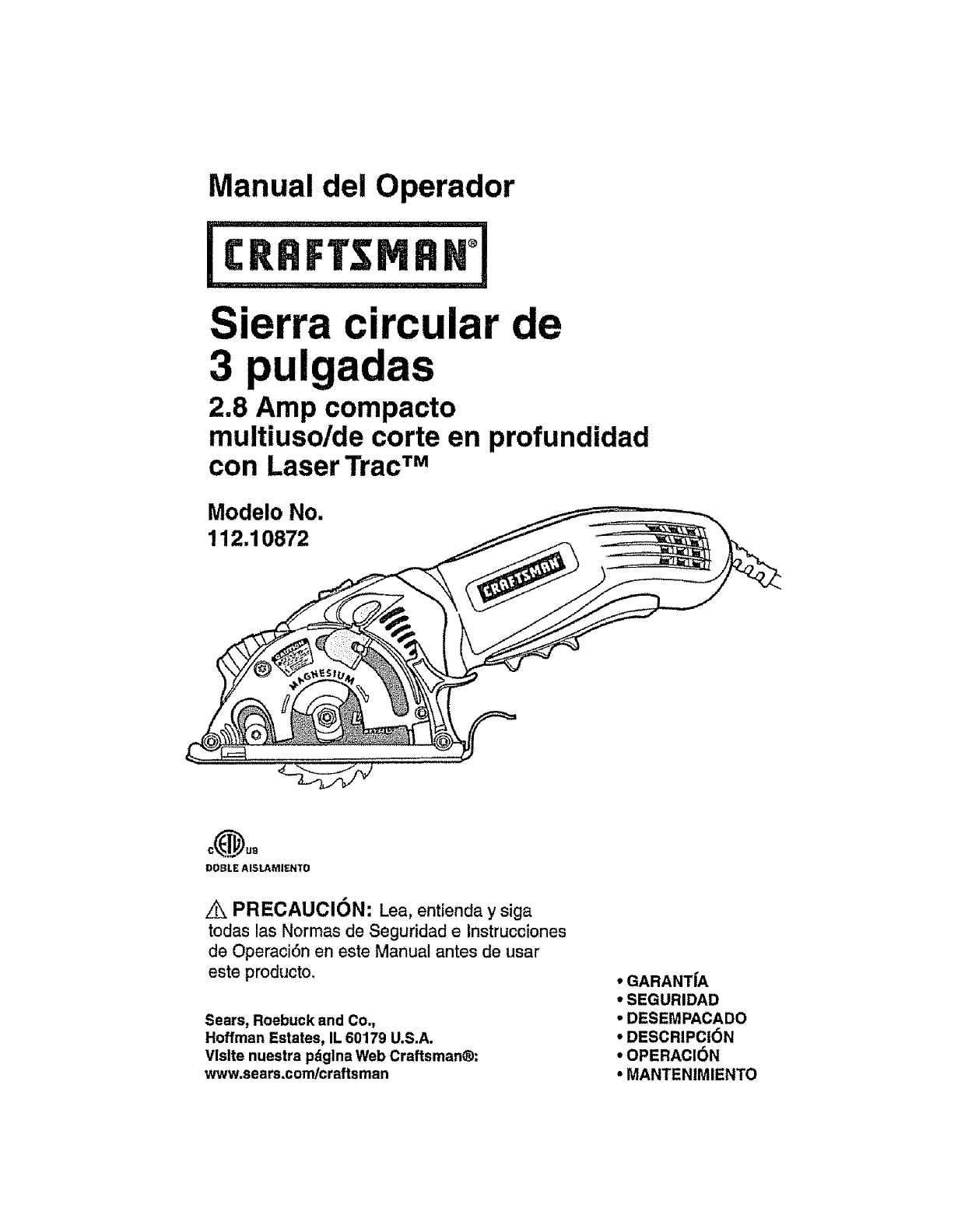
Operator's Manual
2.8 Amp Compact
Multi-Purpose/Plunge Action
3-in. Circular Saw
with Laser Trac TM
Model No.
112.10872
Z_ CAUTION: Read, understand and follow
all Safety Rules and Operating Instructions
in this Manual before using this product_
Sears, Roebuck and Co.,
Hoffman Estates, IL 60179 U.S.A.
Visit our Craftsman ®webslte: www.sears.com/craftsman
• WARRANTY
•SAFETY
• UNPACKING
• DESCRIPTION
•OPERATION
• MAINTENANCE
Warranty ................................................................................... Page 2
Safety Symbols .......................................................................... Page 3
Safety Instructions ...................................................................... Pages 4-11
Glossary of Terms ....................................................................... Pages 11-12
Unpacking ................................................................................. Page 13
Description ......................................................................................... Pages 14-15
Operation ........................................................................................... Pages 16-31
Maintenance ...................................................................................... Pages 31-32
Troubleshooting ................................................................................. Pages 33-34
Accessories ....................................................................................... Page 35
Repair Parts ....................................................................................... Pages 35-38
Sears Repair Parts Phone Numbers ................................................. Back Cover
ONEYEAR FULLWARRANTY ON CRAFTSMAN ®PRODUCT
tf this Craftsman Tool fails due to a defect in material or workmanship
within one year from the date of purchase, RETURN ITTO ANY SEARS
STORE OR PARTS AND REPAIR CENTER OR OTHER CRAFTSMAN
OUTLET IN THE UNITED STATES FOR FREE REPAIR (OR
REPLACEMENT IF REPAIR PROVES IMPOSSIBLE),
This warranty does not include expendable parts such as lamps, batteries,
bits or blades
if this Craftsman product is used for commercial or rental purposes,
this warranty applies for only 90 days from the date of purchase.
This warranty gives you specific legal rights, and you may have other rights,
which vary from state to state.
Sears, Roebuck and Coo, Hoffman Estates, IL 60179
SAVETHESE INSTRUCTIONSI
READ ALL INSTRUCTIONSI
,4k WARNING: Some dust created by using power tools contains
chemicals known to the State of California to cause cancer and birth
defects or other reproductive harm.
The purpose of safety symbols is to attract your attention to possible dangers.
The safely symbols, and the explanations with them, deserve your careful attention
and understanding, The symbol warnings DO NOT by themselves eliminate any
danger, The instructions and warnings they give are no substitutes for proper accident
prevention measures,
AWARNING: BE SURE to read and understand all safety instructions in this
manual, Including al! safety alert symbols such as "DANGER", "WARNING" and
"CAUTION", BEFORE using this saw. Failure to follow all instructions listed below
may result in electric shock, fire and/or serious personal injury.
SYMBOL MEANING
l/e_ sAFETY ALERT sYMBOL: IndIcates DANGER'WARNING'OR 1
CAUTION.Maybe usedIn conjunctionwith othersymbolsor plctographe.
[-_ DANGER: Failure to obey this safety warning WILL result in |
1
death or serious Injury to yourself or to others. Always follow l
the safety precautions to reduce the risk of fire, electric shock
and personal Injury.
[ _WARNING ]Failure to obey this safety warning CAN result In death or I
]serious Injury to yourself or to others. Always follow the safety
precautions to reduce the risk of firs, electric shock and
persons! Injury.
|
,'_ CAUTION IFailure to obey this safety warning MAY result In personal I
injury to yourself or others or property damage, Always follow
lthe safety precautions to reduce the risk of fire, electric shock t
and personal Injury,
DAMAGE PREVENTION AND INFORMATION MESSAGES
These Informuser of important Information and/or Instructions that could lead to
equipment or other property damage _fnot followedoEach message ts preceded by the word
"NOTE:" as in the example below:
NOTE: Equipment and/or property damage may result If these Instructions are
not followed. J
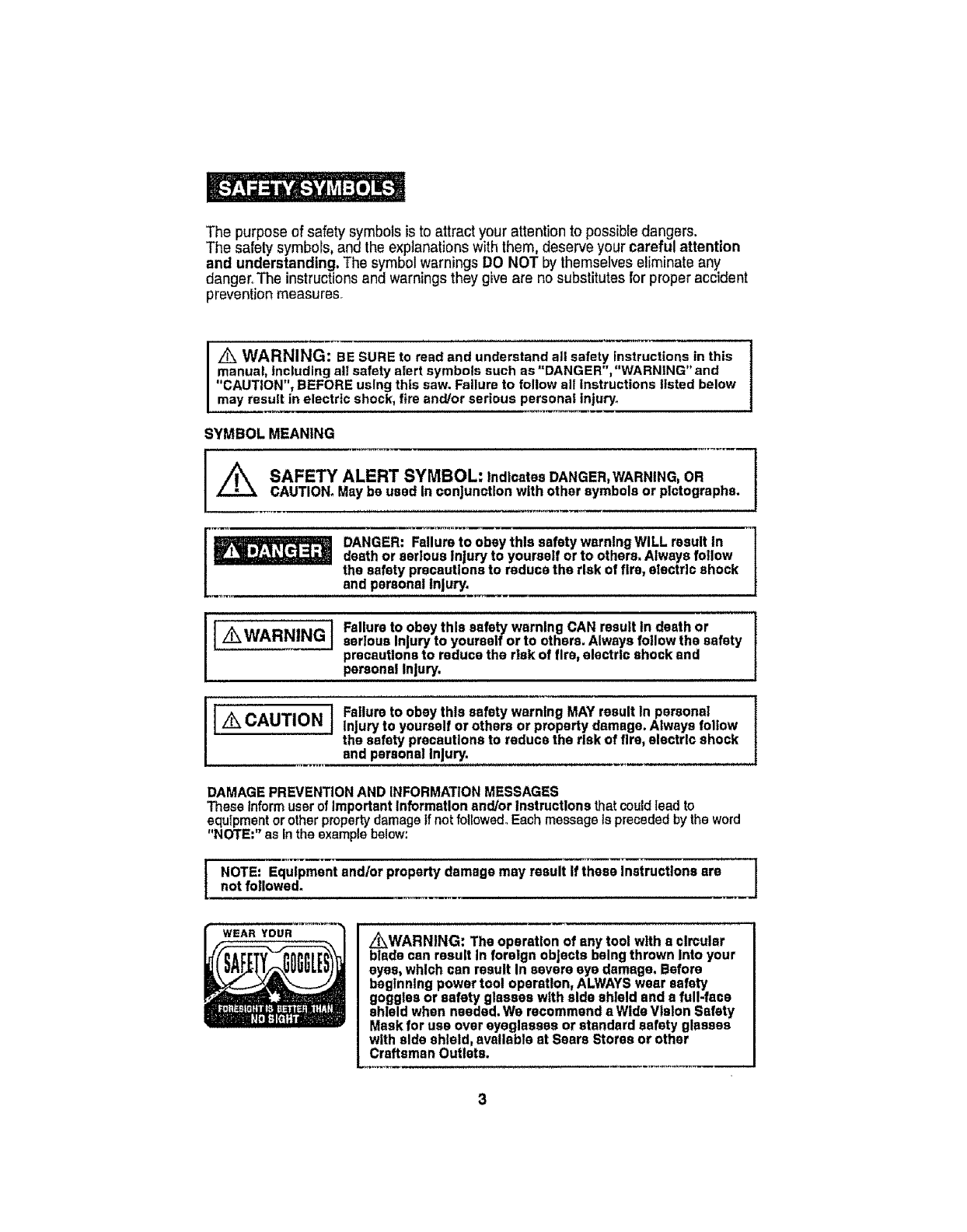
WEAR YOUR _WARNING: The operation of any tool with s ¢lmular
btade can result in foreign objects being thrown into your
eyes, which can result In severe eye damage. Before
beginning power tool operation, ALWAYS wear safety
goggles or safety glasses with aide shield and s full-face
shield when needed. We recommend a Wide V|slon Safety
Meek for use over eyeglasses or standard safety glasses
with side shield, available at Sears Stores or other
Craftsman Outlets.
z_WARNING: BE SURE to read and understand all Instructions In this manual t
before using this circular saw. Failure to follow all Instructions may result In t
hazardous radiation exposure, electric shock, fire and/or serious personal Injury,!
SAFETY PRECAUTIONS FOR LASERS
This saw has a built-in laser light.The laseris aClassIlia and emits outputpower of a
maximum 2.5mWand 635-665nmwavelengths.These lasersdo notnormallypresent
an opticalhazard.However,DO NOT stareat the beam asthiscancause flash
blindness,
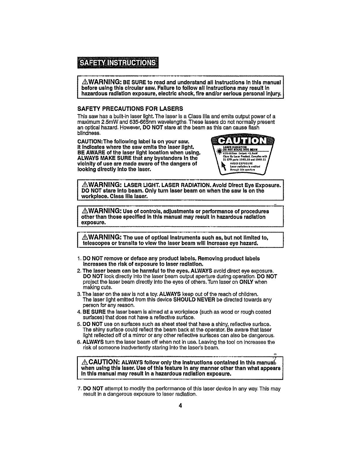
CAUTION:The following label Is on your saw.
It Indicates where the saw emits the laser light,
BE AWARE of the laser light location when using,
ALWAYSMAKE SUREthat any bystanders In the
vlclnlty of use are made aware of the dangers of
looking directly Into the laser.
2t Cf'R _1040,10 _¢4 1_10,t_t
A_tD [KPOSU_1_
_WARNING: LASER LIGHT. LASER RADIATION.Avoid Dlrect Eye Exposure.
DO NOTstare Into beam. Only turn laser beam on when the sew Is on the
workplece. Class Ilia laser.
z_WARNING: Use of controls,adjustments or performanceof procedures ]
other than those speclfled in this manual may result In hazardousradiation f
exposure.
I WARNING: The use of opticalinstruments such as, but not limitedto, ]
telescopes or transits to view the laser beam will Increase eye hazard. !
t_DO NOTremove or deface any product labels. Removing product labels
Increases the risk of exposure to laser radlatlon,
2. The laser beam can be harmful to the eyes, ALWAYSavoiddirect eye exposure.
DO NOT look directly Intothe laser beam output aperture during operation_DO NOT
project the laser beam directly Into the eyes of others,Turn laser on ONLY when
making cuts.
3. The laser on the saw is nota toy.ALWAYS keep out of the reach of children,
The laser light emitted from this devlca SHOULD NEVER bedirected towards any
personfor any reason.
4. BE SURE the laser beam is aimed at a workptece (suchas wood or rough coated
surfaces) that does not have a reflective surface.
5. DO NOTuse on surfaces such assheet steel that have a shiny, reflective surface.
The shiny surface could reflect the beam back at the operator°Be aware that laser
light reflected off of a mirror or any other reflective surfaces can also be dangerous.
6. ALWAYSturn the laser beam off when not in use. Leaving the toolon Increasesthe
risk of someone inadvertently staring Into the laser's beam°
_CAUTION' ALWAYSfollow only the Instructions contained In this manua-(_
when usingthis laser, Use of this feature In any manner other than what appears
In this manual may result In a hazardous radiation exposure,
7. DO NOTattemptto modify the performance of this laser device inany way.Thls may
resultina dangerousexposureto laser radiation.
SAFETY PRECAUTIONS FOR LASERS cont.
8. ALWAYSuse only the accessories that are recommended by Sears for use withthis
product° Use of accessories that have been designedfor use with other laser tools
could result in serious Injury.
9. For further Information regarding lasers, refer to ANSI-Z136.1 The STANDARD FOR
THE SAFEUSE OF LASERS,avaUabiefromthe Laser Instituteof America (407)380-1553.
WORK AREA SAFETY
1.Keep your work area clean and well lit. Clutteredworkbenchesanddarkareas
invite accldents.
2, DO NOT operate power tools In explosive atmospheres, such as In the presence
of flammable liquids, gases, or dust, Powertools createsparks whichmayIgnite
the dust or fumes_
3, Keep bystanders, children and visitors awaywhile operating a power tool,
Distractions can cause youto lose control_
4. Make your workshop chlidproof withpadlocks and master switches. Lock
tools awaywhen not inuse.
5, MAKE SURE the work area has ample fighting so you can see the work and that
thereare no obstructionsthat willinterferewithsafeoperationBEFORE usingyoursaw,
PERSONAL SAFETY
1_KNOW your power tool. Read the operator'smanual carefully.Learn the saw's
applications and limitations, as wellas the specific potential hazardsrelated to this tool,
2. STAYALERT, watch what you are doing and use common sensewhen operating
a power tool
3oDO NOT use tool white tired or under the influenceof drugs, alcohol or medlcatlono
A moment of inattentionwhite operatingpower tools may result insertouspersonal Injury,
4. DRESSproperly, DO NOT wear looseclothing or Jewelry.PuUback tong hair. Keep
your hair, clothing, and gloves away from moving parts. Air vents often cover moving
parts and shouldalso be avoided. Loose clothing, jewelryor long hair can be caught
In movlng parts.
5. AVOID accidental starting. Be sure switch ls in"OFF" positionbefore plugging lm
DO NOTcarry tools with your finger on the switch.Carrying tools with your finger on the
switchor plugging in tools that have the switch In the "ON" position Invltesaccidents.
6. REMOVE adjusting keys or wrenches before turning the tool "ON". A wrench
that Is leftattached to a rotatlng part of the tool may resultIn personalinjury,
7, Do not overreach. Keep proper footing and balance at all times. Properfooting
and balance snabresbetter control of the toolinunexpected sJtcattons.
8oALWAYSSECURE YOURWORK. Usa clampsor a vise to hold work when practical.
It is safer than using your hand and freesboth hands to operate tool.
9oUSE SAFETY EQUIPMENT.Always wear eye protection. Dust mask, non-skid safety
shoes,hard hat, or hearing protection must be used for appropriate conditions°
t0. DO NOT USE ON A LADDER or unstable support. Stable footing on a sol]d surface
enables better control of the tool in unexpectedsituations.
5
TOOL USE AND CARE SAFETY
/_WARNING: BE SURE to read and understand all instructions before
operating this saw. Failureto follow all instructions listed below may result in Jelectric shock, fire and/or serious personal injury.
1_ALWAYSuse clamps or other practical ways to secure and support the
workplece to a stable platform. Holdtngthe workby handor againstyourbodyis
unstableand maylead to lossofcontrol
2oDO NOTforce the tool. Use the correct tool and blade for your application.
The correcttool and blade willdothe job better and saferat the rate forwhichIt is
deslgnedo
3. DO NOT use the tool If switchdoes not turn It "On" or "Off", Any tool that cannot
be controlled with the switch tsdangerous and must be repaired°
4, DISCONNECTthe plug from the power source before making any adjustments,
changing accessories or storing the tool, Such preventivesafetymeasures reduce
the riskofstartingthe toolaccidentally.
5. NEVER leave the tool running,ALWAYSturn tt off, DO NOT leave the tool untilIt
comesto acompletestop.
6. STOREIdle tools out of the reach of children and other untrained persons.
Toolsare dangerous inthe handsof untrainedusers°
7. MAINTAINtoolswith care. Keepcutting tools sharp end clean, Properlymaintained
toolswithsharp cuttingedgesare less likelyto bind andare easierto control
8. CHECK for mlsailgnment or binding of moving pads, breakage of pads, andany
otherconditionthat may affectthe tool's operation.If damaged, have thetoolserviced
beforeusing.Manyaccidentsare causedby poorlymaintainedtools.
g°USE ONLYaccessories that are recommended for this tool, Accessoriesthatmay
be suitable forone tool maybecome hazardous when usedon another tool.
10. KEEP blade guards In place and in good working order,
ELECTRICAL SAFETY
_WARNING: Do not permit fingers to touch the terminals of plug when
Installingor removing the plugfrom the outlet,
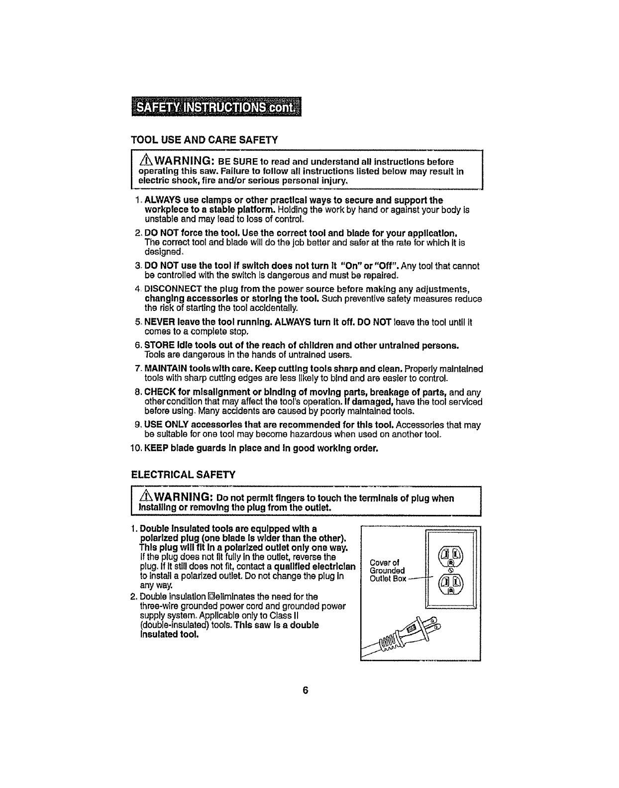
1.Double Insulated tools are equipped with a
polarizedplug (one blade Is widerthan the other),
Thls plugwill fit In a polarized outlet only one way,
Ifthe plugdoes not fit fully inthe outlet,reversethe
plug. If It still does not fit, contact a qualifiedelectrician
to Installa polarized outlet. Do not change the plug in
anyway.
2. Doubleinsulation[]eliminates the need forthe
three-wiregroundedpower cord end grounded power
supplysystem.Applicable only to Class Ii
(double-insulated)tools. This saw Isa double
Insulated tool,
Cover of
Grounded
Outlet Box _ (_
ELECTRICAL SAFETY cont.
_WARNING: Double Insulation DOES NOTtake the place of normalsafety
precautionswhen operating thistool.
3. BEFORE plugging in thetool,BE SURE that the outlet voltage supplied ts wlthin the
voltage marked on the tool's data plate. DO NOT use "AConly"rated tools with a DC
power supply°
4.AVOID body contact with grounded surfaces, suchas plpes,radiators,rangesand
refrigerators.There isan increasedrtskof electricshockifyourbody ts grounded_
5, DO NOT expose power tools to rain or wet conditions or use power tools In wet
or damp locetlons. WaterenteringapowertoolwfilIncreasethe riskof slectdcshock.
6. INSPECT tool cords for damage. Have damaged toolcords repalredat a Sears
ServiceCenter°BE SUREto stayconstantlyaware of the cordlocation and keep itwell
away from the moving blade.
7. DO NOT abuse the cord.NEVER use the cord to carry the tool by or pull the plug
from the outlet. Keepcordawayfrom heat,otl,sharpedgesormoving parts°Replace
damagedcordsimmediately.Damagedcordsincreasethe riskof electricshock_
EXTENSION CORDS
Use a proper extension cord. ONLYuse cordslisted by UnderwritersLaboratories(UL)_
Other extensioncordscan causea drop in line voltage,resulting ina loss of powerand
overheatingof tool.
Forthis tool an AWG (AmericanWire Gauge)size ofat least 14-gauge is recommended
for an extension cord of 25-ft. or less inlength. Use 12-gauge for an extensioncord of
50-ft, Extension cords 100..ft,or longer are not recommended,Remember, a smaller
wire gauge size has greater capacity than alarger number (14-gaugewirehas more
capacitythan 16-gauge wire;12-gauge wirehas more capacitythan14-gauge)oWhen In
doubt usa the smaller number.
When operatinga power tooloutdoors, use an outdoorextensioncordmarked"W-A" or
"W".These cords are rated for outdoor use andreduce the risk of electrlc shock.
Z_ CAUTION= Keep the extensioncord clearof the working area. Positionthe /
cord so that It will not get caught on the workplece,tools orother obstructions J
while you are worklng with a powertool,
Z_WARNING: Checkextensioncords before each use.if damaged replace ]
Immediately.Never use tool with a damaged cord since touchingthe damaged J
area could cause electrical shock,resulting In seriousInjury.
SAFETYSYMBOLSFORYOURTOOL
Thelabelonyourtoolmay Include the following symbols.
V...............................................................................Volts
A..............................................................................Amps
Hz.............................................................................Hertz
W.............................................................................Watts
mln..........................................................................Minutes
.............................................................................Alternatingcurrant
............................................................................Directcurrent
no............................................................................No-loadspeed
[] .............................................................................ClassII construction,DoubleInsulated
.../mln.........................................................................Revolutionsor StroPsper minute
L_o............................................................................Indicatesdanger,warningorcaution.
It means attentlonl Yoursafetyis Involvedo
SERVICE SAFETY
1. If any part of this saw Is missing or should break, bend,or fall In any way;
or should any electrical component fall to perform properly;SHUT OFF the power
switch and removethe saw plugfrom the powersource and have the missing.
damaged or failed partsreplacedBEFORE resumingoperation.
2. Tool service must be performed only at a Sears Parts and Repair Center,Service
or maintenanceperformedby unqualifiedpersonnelcouldresult In a riskof injury.
3. When servicing a tool, use only Identical replacement parts. Follow Instructions
Inthe maintenance section of this manual. Use of unauthorizedpartsorfailure to
follow maintenanceInstructions may createa risk of electricshock or injury.
SAFETY RULES FOR THE MULTI-PURPOSE/PLUNGE ACTION
3-IN. CIRCULAR SAW
I _ Keep hands awayfrom cuttingarea and blade. Keep one hand
onthe trigger switchand the other hand on the handle/motor housing.If both
hands are holding the saw, the blade cannot cut them.
[Z_ CAUTION: Blades coast after saw Is switched off. ]
1, KEEP your body positioned to either side of the saw blade and not in direct line
with the saw blade. Kickbackcouldcausethe sawto jump backwards.
(See"Ktckback...What CausesIt andWaysto Help PreventIt"onpages1B.19 and20).
2. DO NOT reach underneath the workplece. The blade extendsbeneath the
workplacewhencuttingand couldcauseinjury.
l_r_j.-=J"_ When sawingthrough aworkplece,the lower blade guard and
base DO NOT coverthe blade.The blade Is below the lower blade guardend base
(Pagi_25).ALWAYSKeepyour hands andfingers awayfrom the cuttingarea.
CAUTION: This circularsaw DOES NOThave the standard RETRACTABLE
LOWER BLADE GUARDSystemfound on standard circularsaws. ONTHIS saw
the lower blade guard Is an Integral part of the saw's base (cutting platform)and
ONLYenclosesthe blade when it Is ABOVE the base.
8
SAFETY RULES FOR THE MULTI-PURPOSE /PLUNGE ACTION
3-IN. CIRCULAR SAW cont.
/_ CAUTION: When the blade Is plunged below the base to make the cut,
the blade Is entirely exposed underneath the workplace until It cuts through and
clearsthe workplece;at this point the blade guard and base wilt automatically
"DROP" down and lock the blade ABOVE the base,enclosing the blade In the
upperand lower blade guard.
CAUTION: FAMILIARIZEYOURSELFWITHTHIS BLADE GUARDSYSTEM
and the PLUNGE ACTION (lowering blade to desired depth) BEFORE USING
THIS SAW (See Page 18, Figs. 4 and 4e).
3_CHECK the Blade Guard Release Leverand the LowerBlade Guardand Base
BEFORE each use, DO NOT OPERATE the saw if the }owerblade guard and base
does not move freely and DROP DOWN INSTANTLY,and the blade guard release
lever does net automatically engage the upperblade guard, AFTER cut Ismade
and blade c{earsthe workptece(See Page 18 and 19).
Iz_ CAUTION: Never clamp or tie the Blade Guard Release Lever and the
Lower Blade Guard and Base in the raised position exposing the blade.This
would notallow the lower Blade Guard and Base Assembly to function properly
after the cuttingoperation, Increasing the risk of serious personal Injury.
4. ONLYUSE the manual Blade Guard Release Lever to false the base, lowering the
bladeto the desired depth-of-cut whenbeginning the cuttingoperatlon_
5_If the saw Isaccidentally dropped, the blade guard release lever and the lower blade
guard and base could be damaged or broken. Lower and raise the blade manually
(see page 18, Figs.4 and 4a) to be sure the release lever,guard and base all operate
properly.
6otf the BladeGuard Release Lever or LowerBlade Guard and Base or any other part of
the saw is not operating properly, the saw MUST BE serviced before use.
7. ALWAYSmake sure that the Lower Blade Guard and Base ts covering the blade, and
the Blade Guard Release Lever has engaged and locked the blade ABOVE the base
BEFORE placing the saw down on a workbench or floor,
Placing the sawdown before the lower blade guard and base and blade guard release
lever have properly closed and locked could leave the blade exposed below the base,
Increasingthe risk of seriouspersonal Injury. Make note of the time It takes for the
blade to stopsplnnlng and the guard, base and release lever to drop and lock intothe
guarded position,
8. NEVER hold the piece being cut In your hands or across your legs, It isimportantto
support the workplace propedy tn order to minimize body exposure, blade binding, or
loss of control
9-HOLDTOOL by Insulated gripping surfaces (handle/saw's body) when performing an
operation where the cutting tool may contact hidden wiring or Its own cord.Contactwith
a "llve" wire wLllmake the exposed metal parts of the tool "live"and shockthe operator.

SAFETY RULES FOR THE MULTI-PURPOSE /PLUNGE ACTION
3-IN. CIRCULAR SAW cont.
10rALWAYSclampthe workplece securely so It will not move when making the cut.
11oWhen ripping, ALWAYSUSE a rip fence or straight edge guide.This Improves
the accuracy of the cut and reduces the chance of the blade binding.
[ WARNING: ONLY USE the blades that are designated for use with this
saw; correct size, shape and arbor hole. Other blades could run erratically and
cause loss of control, resulting In serious Injury (see pages 16 and 17).
12, NEVER use damaged or Incorrect blade washers or bolts. The blade washers
and bolts were specially designed for your saw, for optimum performance and
safety of operation,
13_ONLYUSE the designated blades for cuffing the type of material for which they
are recommended. Cutting materialsthat are NOTrecommended could cause
blade breakage and lossof control, resulting In serious Injury,
14,NEVER cut more than one piece at a time. DO NOT STACKmore than one
workplece on the worktable at a time.
15, AVOID awkward operations and hand positions where a sudden slip could
cause your hand to move into the blade.
16. NEVER reach Into the cutting pathof the blade.
/_ WARNING: Some dust created by using power tools contains chemicals
known to the State of California to cause cancer and birth defects or other
reproductive harm_Some examples of these chemicals are:
•Lead from lead-based paints.
•Crystalline silica from bricks and cement and other masonry products_
•Arsenic and chromium, from chemically treated lumber.
Your risk from these exposures varies, depending upon how often you do this
type of work.To reduce your exposure to these chemicals:
• Work in awell-ventilatedarea°
,,Work with approved safety equipment, such as those dust masks that are specially
designed to filter out microscopic particles..
Avoid prolonged contact with dust from power sanding, sawing, grinding, drilling
and other construction activities.Wear protective clothing and wash exposed
areas with soap and water.
Allowing dust to get tntoyour mouth, eyes, or lay on the skin may promote absorption of
harmful chemicals.
Z_ WARNING: Use of this tool can generate and/or disburse dust, which may
cause serious and permanent respiratory or other Injury. Always use NIOSH/OSHA
approved respiratory protection appropriate for the dust exposure. Direct particles
away from face and body.
I0
ADDITIONAL RULES FOR SAFE OPERATION
Z_ WARNING: BE SURE to read and understand all instructions, Failure to
follow all instructions listed below may result in electric shock, fire and!or serious
personal injury,
1. Know your power tool. Read operator's manual carefutlyo Learn the applications
and limitations, as well as the specific potential hazards related to this tool Following
this rule wilt reduce the risk of electric shock, fire or serious injuryr
2ALWAYS wear safety glasses or eye shields when using this saw, Everyday
eyeglasses have only impact-resistant lenses; they are NOT safety glasses
3, PROTECT your lungs. Wear a face mask or dust mask ifthe operation is dusty
4, PROTECT your hearing. Wear appropriate personal hearing protection during use,
Under some conditions noise from this product may contribute to hearing loss.
5. ALL VISITORS AND BYSTANDERS MUST wear the same safety equipment that the
operator of the saw wears
6INSPECT the tool cords periodically and if damaged have them repaired at your
nearest Sears Service Center. BE AWARE of the cord location,
7 ALWAYS check the tool for damaged parts. Before further use of the tool, a guard or
other part that is damaged should be carefully checked to determine if it will operate
properly and perform its intended function.Check for misalignment or binding of
moving parts, breakage of parts, and any other condition that may affect the tool's
operation. A guard or other part that is damaged should be properly repaired or
replaced at a Sears Service Center_
8. INSPECT and remove all nails from workpiece before sawing.
9, SAVE THESE INSTRUCTIONS. Refer to them frequently and use them to instruct
others who may use thls tool. tf someone borrows this tool, make sure they have
these instructions also,
Spindle
The shaft on which a blade or cutting tool is mounted Also cailed the Arbor
Revolutions Per Minute (RPM)
The number of turns completed by a spinning object in one minute.
Saw Blade Path
The area over, under, behind or in front of lhe blade, as itapplies to the workpiece,
That area which will be or has been cut by the blade
Set
The distance that the saw blade tooth is bent (or set) outward from the face of the blade
Plunge Cutting
A cutting operation in the middle or interior of a workpiece, where the blade is lowered
down into the workpiece to make a pocket cut,,
Miter Cut
A cutting operation made with the blade at any angle other than 90° to the fence.
11
Compound Miter Cut
A compound miter cut is a cut made using a miter angle and a bevel angle at the same
time.
Cross Cut
A cutting or shaping operation made across the grain of the work piece°
Bevel Cut
A cutting operation made with the blade at any angie other than 90 ° to the miter table.
Dado Cut
A non-through cut wllich produces a square-sided notch or trough in the workpiece
(requires special blade).
Chamfer Cut
A cut removing a wedge from a block of wood so the end (or part of the end) is angled at
other than 90 °.
Ripping or Rip Cut
A cutting operation along the lengthof the workpiece,or cutting along the grain.
Freehand Cut
Performing a cut without using a fence, miter gauge, fixture, work clamp, or other proper
device to keep the workpiece from twisting or moving during the cut
Through Sawing
Any cutting operation where the blade extends completely through the thickness of the
workpiece.
Non-Through Cuts
Any cutting operation where the b_ade does not extend completely through the thickness
of the workpiece, like a dado cut.
Leading End (or Edge)
The end (edge) of the workpiece that the blade entersfirst
Kerr
The material removed by the blade in a through cut or the siot produced by the blade in
a non-through or partial cuL
Kickback
A hazard that can occur when the blade binds or stalls, throwing the saw back toward
operator_
Workptece or Material
The item on which the cutting operation is being done The surfaces of a workpiece are
commonly referred to as faces, ends and edges.
Gum
A sticky, sap-based residue from wood products.
Resin
A sticky, sap-based substance that has hardened.
12
Z_ WARNING: Yoursaw should NEVERbe connected to the power soume
when you are assembling pads, maldng adjustments,Installing or removing
blades,cleaning or when It is not In use.Disconnectingthe sawwill prevent
accidentalstarting, which could cause seriouspersonal Injury.
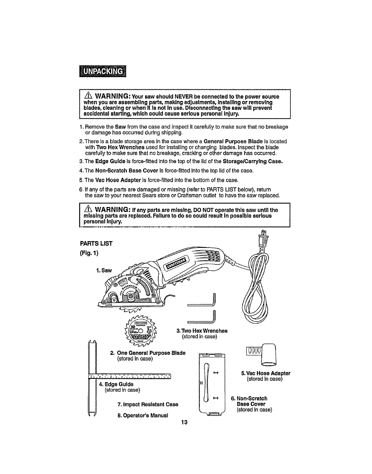
I. Remove the Saw from the case and JnspectIt carefully to makesurethat no breakage
or damage has occurred during shlpplngo
2. There Is a blade storage area inthe case where a General Purpose Blade is located
with "PwoHex Wrenches used for installing or changing blades,Inspect the blade
carefully to make sure that no breakage, cracking or other damage has occurred,
3oThe Edge Guide is force-fitted into the top of the lid of the Storage/Carrying Case,
4,The Non-Scratch Base Cover Is force_fittedInto the top lid of the case_
5oThsVac Hose Adapter is force-fittedIntothebottom of the case.
6. If any of the parts are damaged ormissfng (refer to PARTSLIST below), return
the saw to your nearest Sears store or Craftsmanoutlet to have the saw replacedo
L_ WARNING: If any parts are mlsslng, DO NOT operate this saw unt, the
missing parts are replaced. Failure to do so could result In possible serious
personal Injury.
PARTS LIST
(Fig. 1)
1.Saw
J
7. ImpactResistantCase
8, Operator'sManual "-'-_r
13
5.Vae HoseAdapter
(stored incase)
6. Non-Scratch
Base Cover
(stored in case)
KNOWYOUR MULTI-PURPOSE/PLUNGE ACTION
3-IN. CIRCULAR SAW (Fig. 2)
lNOTE:Before attemptingto use your saw_familiarize yourselfwith allof the
operatingfeatures and safetyrequirements,
Yourplunge actioncircularsawhas a precision-built electric motorand Itshouldbe
connected to a 120-volt,60-Hz AC ONLY power supply(normalhousehold current).
DO NOToperate ondirect current (DC).The largevoltage drop will cause a lossof power
and the motorwill overheat. Ifthe sawdoes not operate when pluggedintocorrect 120-volt,
60*HzAC ONLYoutlet, checkthe powersuppiyoThis saw has an 8-ft., 2*wirepowercord
(no adapter needed).
This Saw has the following features:
1.2.8 Amp, 2800 RPM (no-load speed) Motor. Provtdessurecuts fn plywood,
woodbase composites, plastics, vinyl and fiberglass with the general
purpose blade Included, and ceramic and marble walt tile with the diamond
grit blade soid separately_
2. LaserTracTM the unique, Innovative feature for accurate, efficient cuttlngl
3. Built-in LEDWorkllght illuminatescuttingarea forbetter vistbitityo
4. Quick depth-of-cut adjustments witha maximum depth-of-cut of 7/8-inches.
5. Easy to read and set depth-of-cut scale, located onupper btadeguard, ismarked
in 1/8-in.increments,0 to 7/8-In.withcorrespondinglength(width)of-cuL
6. ErgonomtcallydesignedBlade Guard Release Lever and Base Assembly Finger
Lift forefficient operation of plunge action
7. Length of Cut Indicator, located onbass, shows beginning and end of blade
position on the workpleca; idea! for pocket cutting.
8. Heavy-duty llghtwelght Magnesium blade guardfor extra strength and durability.
9, Stamped and formed steel base and lower blade guard for durability and long life.
10, Non-scratch base cover for use when cutting delicate surfaces such as plastics and
composite flooring.
11. Extended length trigger switchpaddle for right or lefthand control,Trigger safety
release switch convenlently located on paddle for easyoperation.
12. Ergonomlcallydesigned handle with soft-grlp adjusts to 3 different positions at 0°,
15°, and 30°, for more efficientcutting,comfortandmaximum control.
13. Includes One Craftsman®3-In. 20 tooth carbide-tipped steel general purpose
blade for fast, smoothcutsin plywoodupto 3/4-1n,thick,woodbasecomposites,
plastics, vinyland ftberglass.A Craftsman 3-In. diamond grlt steel blade,for cutting
ceramic and marble tile up to 3/8-1n.thick, Is sold separately.
_4. Two Hex wrenches for use when Installingblades_
15. Includes Edge Guide to help produceaccuratestraightcuts.
16. Bullt-lnsawdust extraction port. Includes lib-In, vac hose adapter forhookup
towet/dryvac, soldseparately,to removedustand chipsawayfrom the cuttingarea,
17. Permanently lubricated 100% ball bearings for smoothoperationand longlife.
18. Heavy-duty machined gearlng for efficient powertransmission.
lg. Includes High-Impact resistant carry/storage case.
14
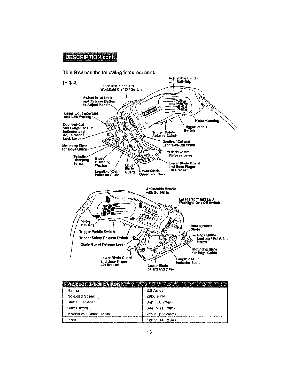
This Saw has the following features: cont.
(Fig.2) Laser Tta¢TM and LED
Workllght On /Off Switch
uetsble Handle
Soft-Grip
Laser Light Aperture
and LEDWorkllgh
Depth-of-Cut
and Length-of-Cut
Indicator and
Adjustment /
Lock Lever
for Edg_
iplng
Screw Clamping
Washer Upper
Blade
Length-of-Cut Guard
Indicator Scale Lower Blade
Guard sod Base
"Lower Blade Guard
and Base Finger
Lift Bracket
Adjustable Handle
with Soft-Grip
LaserTrac TM and LED
Workllght On /Off Switch
Motor
Housing
"l_lggerPaddle Switch
Blade Guard Release
Lower Blade Guard
and Base Finger
Lift Bracket Lower Blade
Guard and Base
Dust Ejection
,Chute
a Guide
I/Retaining
Mounting Slots
for Edge Gulde
Length_of*Cut
Indicator Scale
Rating
No-Load Speed
Biade Diameter
Blade Arbor
Maximum Cutting Depth
Input
2.8 Amps
2800 RPM
3-in, (76,2mm)
.3g4-1n. (1o ram)
7/8-1n. (22.2mm)
120-v., 60Hz AC
'15
_WARNING: Never use a damaged or Incorrect blade washer or bolt.The
blade washer and bolt were specially designed for your saw, for optimum
performance and safe operation. A 3-Inch blade Is the maximum blade capacity
of your saw. A larger than 3-Inch blade will come In contact with the blade
guard. Also, NEVER use ablade that Is so thick that it prevents the outer blade
washer from engaging with the flat side of the spindle. Blades that are too large
or too thick can result In an accident causing serious Injury.
,,, ,,,,,,,,, ,, ,,,,, ,i,
_WARNING: ONLY USE the saw blades designated for use with this saw.
Using any other blade could result Inan accident causing serious Injury.See
page 17 for designated blades and recommended uses.
_WARNING: Only use the Craftsman ®3-In. 20 tooth carbide-tipped steel
general purpose blade (9-61272 Included), to cut wood, plywood up to _-ln.
thick, woodbase composites, plastics, vinyl and fiberglass. A Craftsman 3-In.
diamond grit steel blade (9-61273 sold separately) Is for cutting ceramic and
marble tile up to 3/8-1n. thlck (See Fig. 3b).
SAW BLADES
All saw blades need to be keptclean, sharp and properlysetin orderto cutefficiently.
Using a dull blade places a heavy load onthe saw and Increases the danger of kickback.
Keepextra blades on hand, so sharp blades are always avaiIable_Gum and wood pitch
hardened on the blade slows the saw down, Use gum and pitch remover, hot water or
kerosene to removethem, DO NOT use gasotlne_
INSTALLING THE BLADE (Figs. 3, 3a and 3b)
,/_WARNING: BE SURE to wear protective work gloves while handling a
saw blade.The blade can Injure unprotectedhands.
L_WARNING: Saw wiUbe extremely hot after use. BE SUREto let saw,
blade and blade spindle clamping screw COOL before changing blades.
,= ,, =,= ,,,,,,l, ,,,,,,,,,,,,,,,,,, ,,,, ,, , ,
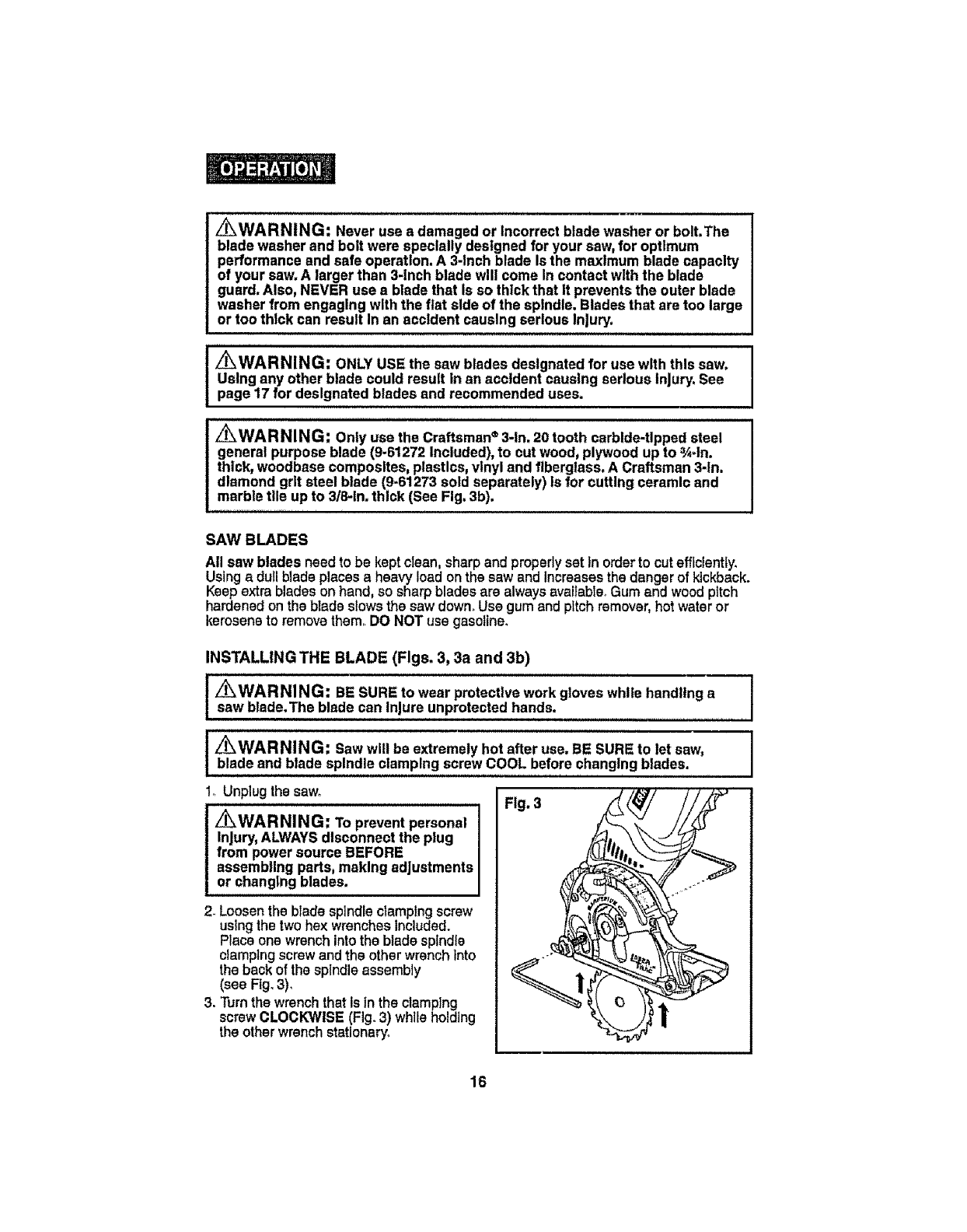
1oUnplugthe saw. Fig. 3
z_WARNING: Topreventpersonal
Injury,ALWAYSdisconnect the plug
from power source BEFORE
assembling parts, making adjustments
or changing blades.
2. Loosen the blade spindle clamping screw
usingthe two hex wrenches Included.
Place one wrench intothe blade spindle
clamping screw and the other wrench Into
the back of the spindle assembly
(see Fig.3),
3. Turn the wrench that Isfn the clamping
screw CLOCKWISE (Fig.3) while holding
the other wrench stationary.
16
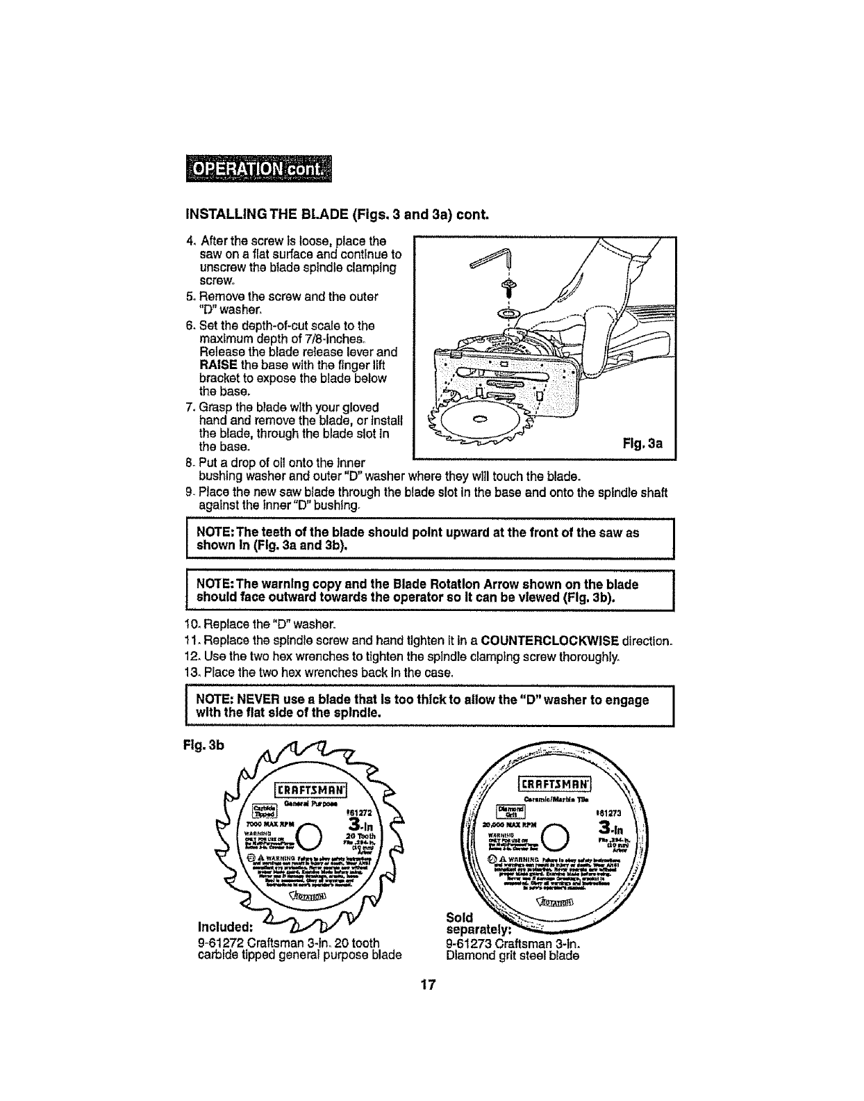
INSTALLINGTHEBLADE(Figs,3and3a)conL
4. After the screw ts loose, place the
saw on s fiat surfaceand continue to
unscrew the blade spindle clamping
screv_,
5oRemove the screw and the outer
"D"washer.
6. Set the depth-of-cut scale to the
maximum depth of 7!8-incheso
Releasethe blade release lever and
RAISE the base with the finger lift
bracket to expose the blade below
the base.
7. Grasp the blade with your gloved
hand and removethe blade, or install
the blade, throughthe blade slot tn
the base. Fig. 3a
8. Put a drop of oil onto the Inner
bushing washerand outer "D" washer where they will touch the blade°
9. Place the new saw blade through the blade slot inthe base and onto the spindle shaft
against the Inner"D" bushtng.
i, u, ,, ,
NOTE:The teeth of the blade should point upward at the front of the saw as
shown In (Fig, 3a and 3b).
NOTE:The warning copy and the Blade Rotation Arrow shown on the blade
should face outwardtowards the operator so It can be viewed (Fig. 3b).
10.Replace the "D" washer.
11. Replace the spindle screwand hand tightenit inaCOUNTERCLOCKWISE direction.
12. Usethe two hex wrenches to tlghten the spindle clamptngscrew thoroughly.
13.PEacethe two hex wrenches back in the case.
INOTE: NEVER use s blade that Is too thick to allow the "D" washer to engage
with the flat side of the spindle,
Fig. 3b
Included:
9-61272 Craftsman 3-In. 20 tooth
carbide tipped general purpose blade
Sold
separately
9-61273 Craftsman 3-1n.
Diamond grit steel blade
17
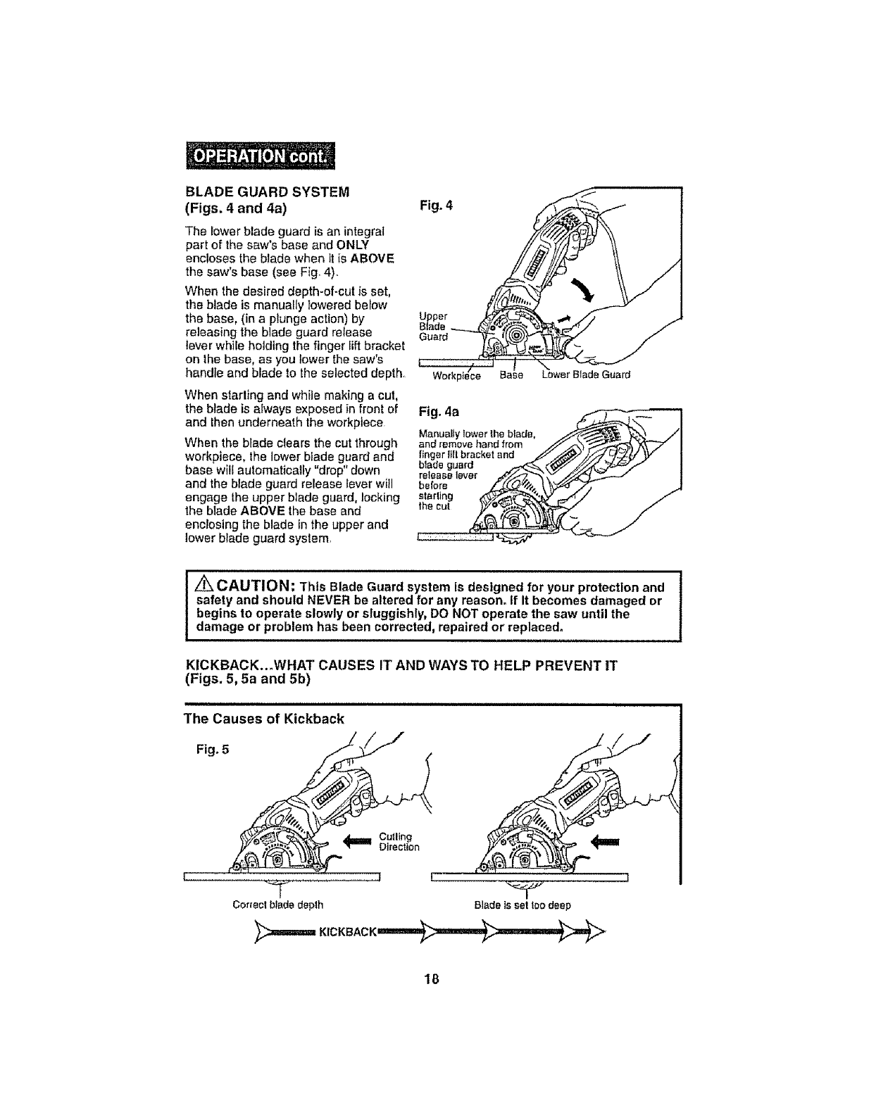
BLADE GUARD SYSTEM
(Figs. 4 and 4a)
The iower blade guard is an integral
part of the saw's base and ONLY
encloses the blade when itis ABOVE
the saw's base (see Fig_4)_
When the desired depth-of-cut is set,
the blade is manually lowered berow
the base, (in a plunge action) by
releasing the blade guard release
lever wh]ie holding the finger lift bracket
on the base, as you lower the saw's
handle and blade to the selected depth,
When starling and while making a cut,
the blade is always exposed in front of
and then underneath the workpiece
When the blade clears the cut through
workpiece, the lower blade guard and
base will automatically "drop" down
and the blade guard release lever will
engage the upper blade guard, locking
the blade ABOVE the base and
enclosing the blade in the upper and
lower blade guard system,
Fig. 4
Upper
Blade
Guard
Fig. 4a
Manually lower the blade,
and remove hand from
fing tand
blade guard
release lever
before
starlin;
the cu!
Z_ CAUTION: 1"his Blade Guard system is designed for your protection and
safety and should NEVER be altered for any reason, If It becomes damaged or
begins to operate slowly or sluggishly, DO NOT operate the saw until the
damage or problem has been corrected, repaired or replaced°
KICKBACK..°WHAT CAUSES IT AND WAYS TO HELP PREVENT IT
(Figs. 5, 5a and 5b)
The Causes of Kickback
Fig, 5 _f_
"_t"-=" Direction
! |
T
Cor_ec!b_ededeplh
1
BladeissetIoodeep
18
KICKBACK..WHAT CAUSES IT AND WAYS TO HELP PREVENT IT
(Figs. 5, 5a and 5b) cont.
The Causes of Kickback cont.
1+KickbackIs a sudden reactionto a pinched, bound or mtsaligned sawblade, which
causes an uncontrolled saw to lift up and out of the workplace and toward the operator_
2. When the blade is pinched or bound tightlyby the kerr cioslng down, the blade stalls
and the motor reaction ddves the unit rapidly backtowards the operator_
3. If the blade becomes twisted or misaltgned in the cut, the teeth at the back edge of the
btade can dig intothe top surface of the wood+This causes the blade to climb out of
the kerf and Jumpback towards the operator,
4. Sawingintoknots or nails inthe workplace can cause Kickback,
5, Sawing intowet or warped lumber can cause Kickback.
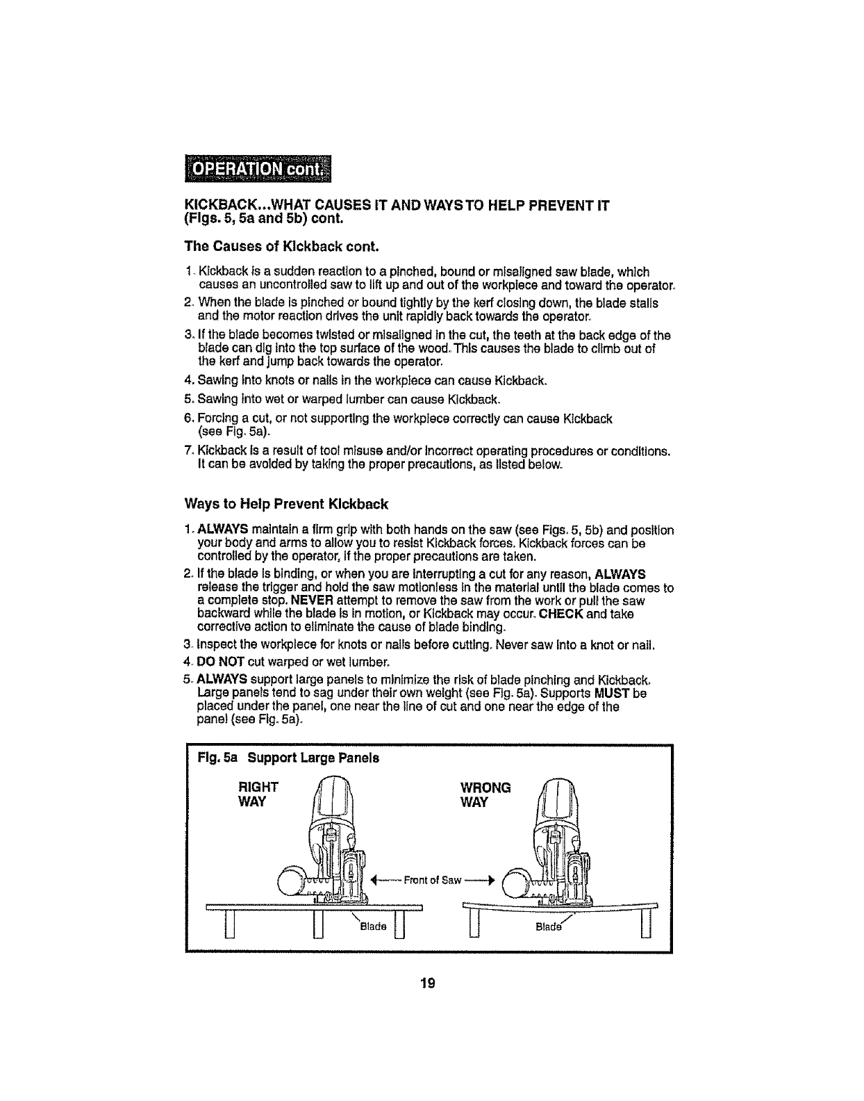
6, Forcing a cut, or not supporting the workplace correctlycan cause Kickback
(see Fig°5a).
7. Kickback Isa result of tool misuse and/or incorrectoperatingprocedures or conditions.
It can be avoided by taking the proper precautions, as listed below.
Ways to Help Prevent Kickback
1.ALWAYSmaintain a firm gdp withboth hands onthe saw (see Figs.5, 5b) andposition
yourbody and armsto allowyou to resistKickbackforces. Kickbackforces can be
controlledby the operator,if the properprecautionsare taken.
2+Ifthe bladeis binding,or whenyouare interruptinga cut for anyreason,ALWAYS
release the triggerand holdthe saw motionless In the material until the blade comesto
a complete stop. NEVER attempt to removethe sawfrom the work or pull the saw
backward while the blade is inmotion, or Kickback may occur.CHECK and take
corrective action to eliminatethe cause of blade binding.
3. Inspectthe workplece for knots or nails before cuttlng°Neversaw into a knot or nail.
4+DO NOT cut warped or wet lumber+
5+ALWAYSsupport large panels to mlnlmize the risk of blade pinching and Kickback,
Large panels tend to sag under theirown weight (see Fig. 5a)°SupportsMUST be
placed under the panel, one near the line of cut and one nearthe edge of the
panel (see Fig.5a)°
Rg. 5a Support Large Panels
I , HlJ "o,+U u ,o°Ju
19
KICKBACK...WHAT CAUSES IT AND WAYS TO HELP PREVENT IT
(Figs. 5, 5a and 5b) cont.
Ways to Help Prevent Kickback cont.
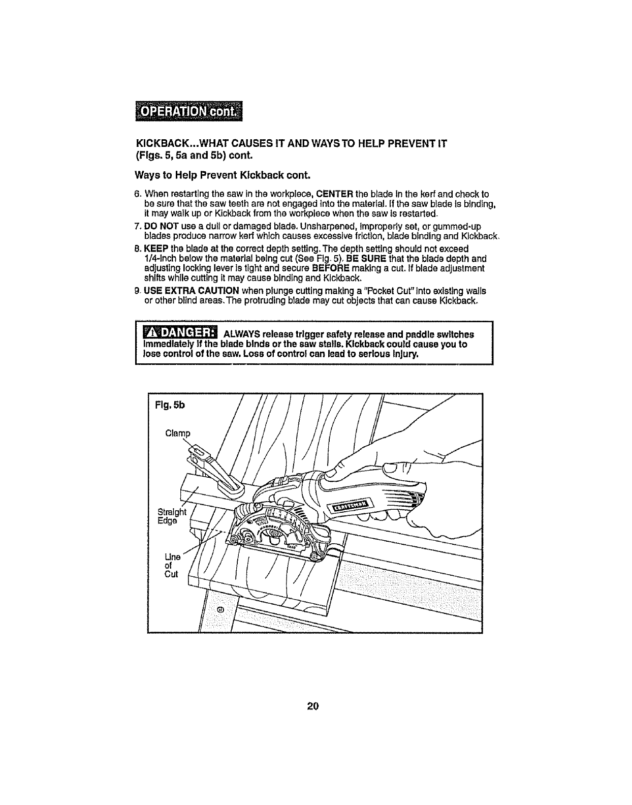
6. When restarting the saw inthe workplece, CENTERthe blade In the keff andcheckto
be sure that the saw teeth are not engaged Into the material. If the saw blade is binding,
it maywalk up or Kickback from the workplece when the saw is restarted_
7oDO NOT use a dull or damaged bladeoUnsharpened, Improperly set, or gummed-up
blades produce narrow kerr which causes excessive friction, blade btndlng and Kickback.
8. KEEP the blade at the correct depth setting. The depth setting should not exceed
1/4-Inch below the material being cut (See Fig. 5). BE SURE that the bladedepth and
adjusting locking lever is tight and secure BEFORE maklng a cut. If blade adjustment
shiftswhile cuttingit maycause binding and Kickback.
9. USE E,I_TRACAUTION when plunge cutting making a "Pocket Cut"Intoexisting walls
or ether bitnd areas.The protruding blade may cut objects that can cause Kickback.
_ALWAYSreleasetrigger safetyreleaseand paddleswitches
Immediatelyif the blade bindsor the saw stalls, Kickbackcould cause you to
lose control of the saw. Loss of control can leadto serious Injury,
Fig, 5b
20
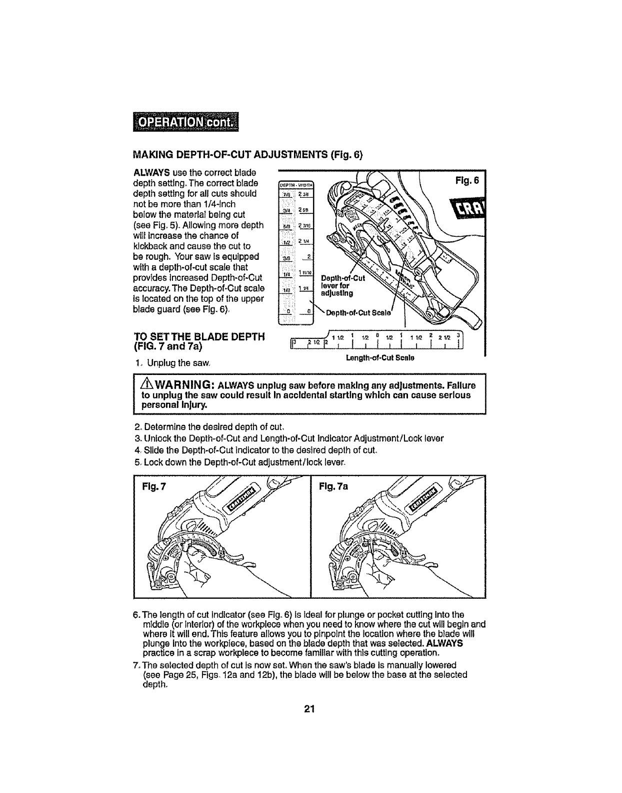
MAKINGDEPTH-OF-CUTADJUSTMENTS(Fig.6)
ALWAYSuse the correct blade
depth setting. The correct blade
depth setting for all cutsshould
not be more than 1/4-Inch
below the material being cut
(see Fig.5). Allowing more depth
wilt increase the chance of
kickback and cause the cut to
be rough. Yoursaw is equipped
with adepth-of-cut scale that
provtdesincreasedDepth-of-Cut
accuracy.The Depth-of*Cutscale
Is located onthe top ofthe upper
blade guard (see Fig.6).
TO SETTHE BLADE DEPTH l
, t , I ,t , H
(FIG. 7 and 7a)
1o Unplug the saw Length-of.CutScald
[ _WARNING: ALWAYSunplug saw before making any adjustments. Failure
to unplug the saw could result In accidental starting which can cause serious
personal injury.
2. Determine the desired depth of cut,
3. Unlockthe Depth-of-Cut and Length-of-Cut IndicatorAdjustment/Lock lever
4. Slide the Depth-of-Cut indicatorto the deslred depth of cut.
5. Lock down the Depth-of-Cut adjustment/lock lever.
Fig, 7
(,
Fig. 7a
6. The length of cut indicator(see Fig. 6) ts idealfor plungeor pocket cutting Into the
m]ddle(orinterior) of the workpfecewhenyouneedto knowwherethe cutwillbegin and
whereit willend.This feature allows youto pinpointthe locationwherethe blade will
plungeInto the workplace,based onthe blade depththat wasselected.ALWAYS
practiceina scrap workplaceto becomefamiliar withthis cuttingoperation.
7_The selecteddepth of cut is now set.When the saw'sblade is manually lowered
dSeePage 25, Figs. t2a and 12b), the blade will be below the base at the selected
epth.
21
ADJUSTING THE 3-POSITION HANDLE (Fig. 8)
Z_WARNING: To prevent personal Injury,ALWAYSdisconnect the plug
from power source BEFORE assembling parts, making adjustments or
changing blades, i
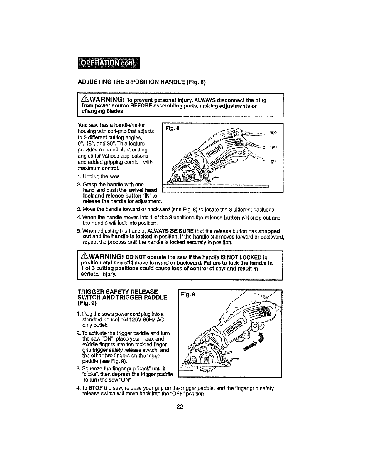
Your saw has a handle/motor
housing withsoft-grip that adjusts
to 3 different cutting angles,
0°, 15°, and 30".This feature
provides more efficient cuttlng
angles for vadous applications
and added gripping comfort with
maximum control.
Fig, 8 3O°
15o
0o
1, Unplug the saw.
2. Graspthe handle with one ............................ j
handand pushthe swivelhead
lock and release button"IN" to
release the handlefor adjustment.
3. Movethe handleforwardor backward (see Fig.8) to locatethe 3 differentpositions.
4_Whanthe handlemovesinto1 of the 3 positionsthe release button willsnapoutand
the handlewilllockintoposition.
5.When adjusting the handle,ALWAYSBE SURE thatthe reteasebutton has snapped
out and the handle Is locked in position.Ifthe handle st_llmoves forward or backward,
repeat the processuntilthe handleIs locked securely inposition.
_WARNING: DO NOT operate the saw If the handle IS NOT LOCKED In
position and can still move forward or backward. Failure to lock the handle In
1 of 3 cutting positions could cause loss of control of saw and result in
serious Injury.
TRIGGER SAFETY RELEASE
SWITCH AND TRIGGER PADDLE
(Fig. 9)
Fig. 9
1. Plugthe saw'spowercordplug Intoa
standardhousehold 120V.60Hz AC
only outlet°
2.To activate the tdggerpaddleandturn
the saw "ON", placeyourIndex and
middle fingersintothe molded finger
griptriggersafety releaseswitch, and
the othertwo fingersonthe trigger
paddle(see Fig.9).
3_Squeeze the fingergrip"back" until it
"clicks",then depress the trigger paddle
to turn the saw"ON",
4, To STOP the saw,release your grip on the trigger paddle, and the finger grip safety
release switchwtl!move back Intothe "OFF" position.
22
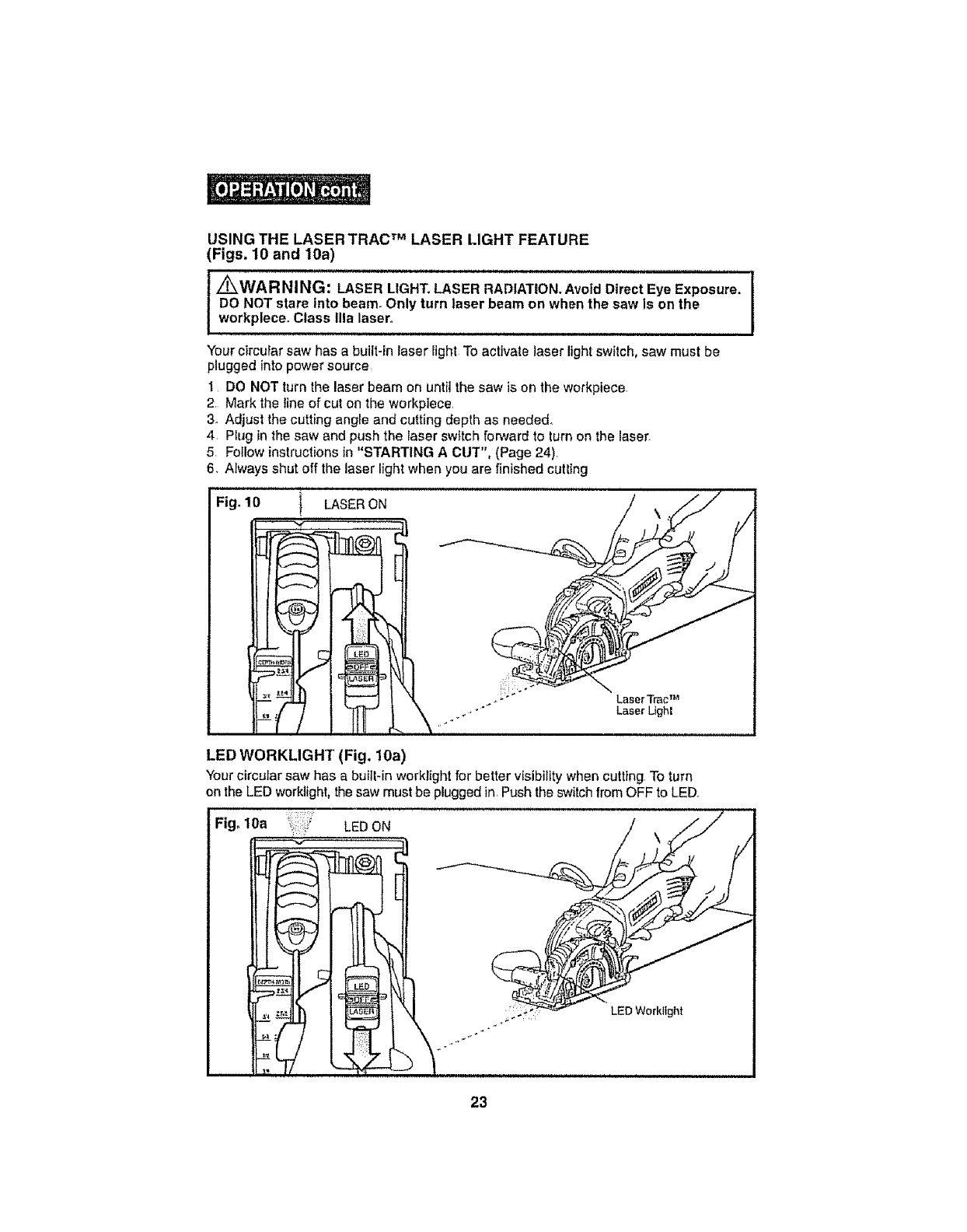
USING THE LASER TRAC TM LASER LIGHT FEATURE
(Figs. 10 and 10a)
................................................................... i
i _WARNING: LASER LIGHT. LASER RADIATION. Avoid Direct Eye Exposure.
DO NOT stare into beam, Only turn laser beam on when the saw is on the
workplece. Class Ilia laser°
ll,l,,,ll i,,Hllll L
Yourcircular saw has a built-in laser light To activate laser light switch, saw must be
plugged into power source
1 DO NOT turn the laser beam on until the saw is on the workpiece.
2, Mark the line of cut on the workptece,
3. Adjust the cutting angle and cutting depth as needed.,
4 Plug in the saw and push the iaser switch forward to turn on the laser.
5. Follow instructions in "STARTING A CUT", (Page 24)
6. Always shut off the laser light when you are finished cutting
Fig. 10 1 LASER ON
Laser TracTM
Laser Light
LED WORKLIGHT (Fig, 10a)
Your circular saw has a built-in worklight for better vtsibi/lty when cutting To turn
on the LED work]ight, the saw must be plugged in, Push the switch from OFF to LED°
Fig. 10a LED ON
23
STARTING A CUT (Figs. 11, 12, 13 and 13a)
/_ WA R NING: ALWAYSclampand supportworkplecesecurely,ALWAYS
maintainproper control of saw. Failureto clampand support workpleceand loss
of controlof saw could result in serious injury.
1o Unplug the saw
_ _WARNING: ALWAYSunplugsaw before making any adjustments.Failure
to unplugthe saw could result in accidentalstartingwhich can cause serious
personal Injury,
2_Set-upand clampyour workplaceand mark your cutline.
3. Set the handle on the saw to the desired angle for your cutting application.
4. Set the Depth-of-Cut (with corresponding Length-of-Cut).
5. Plug In the saw°
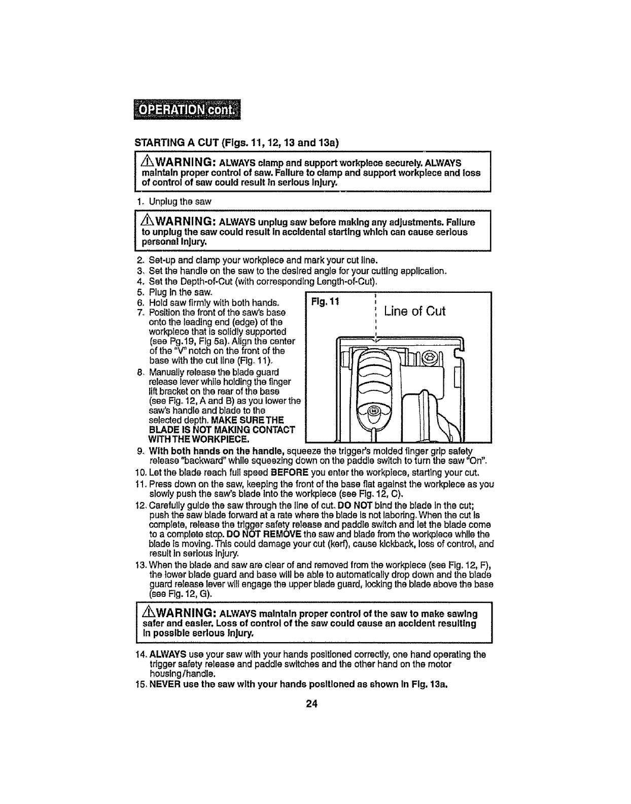
6o Hold saw firmly with both hands. Fig, 11
7_ Positionthe front of the saw's base Line of Gut
onto the leading end (edge) of the
workplace that is solidlysupported
(see Pg.19, Ffg5a)oAlign the center
of the "V" notch on the front of the
base with the cut line (Fig°11)o
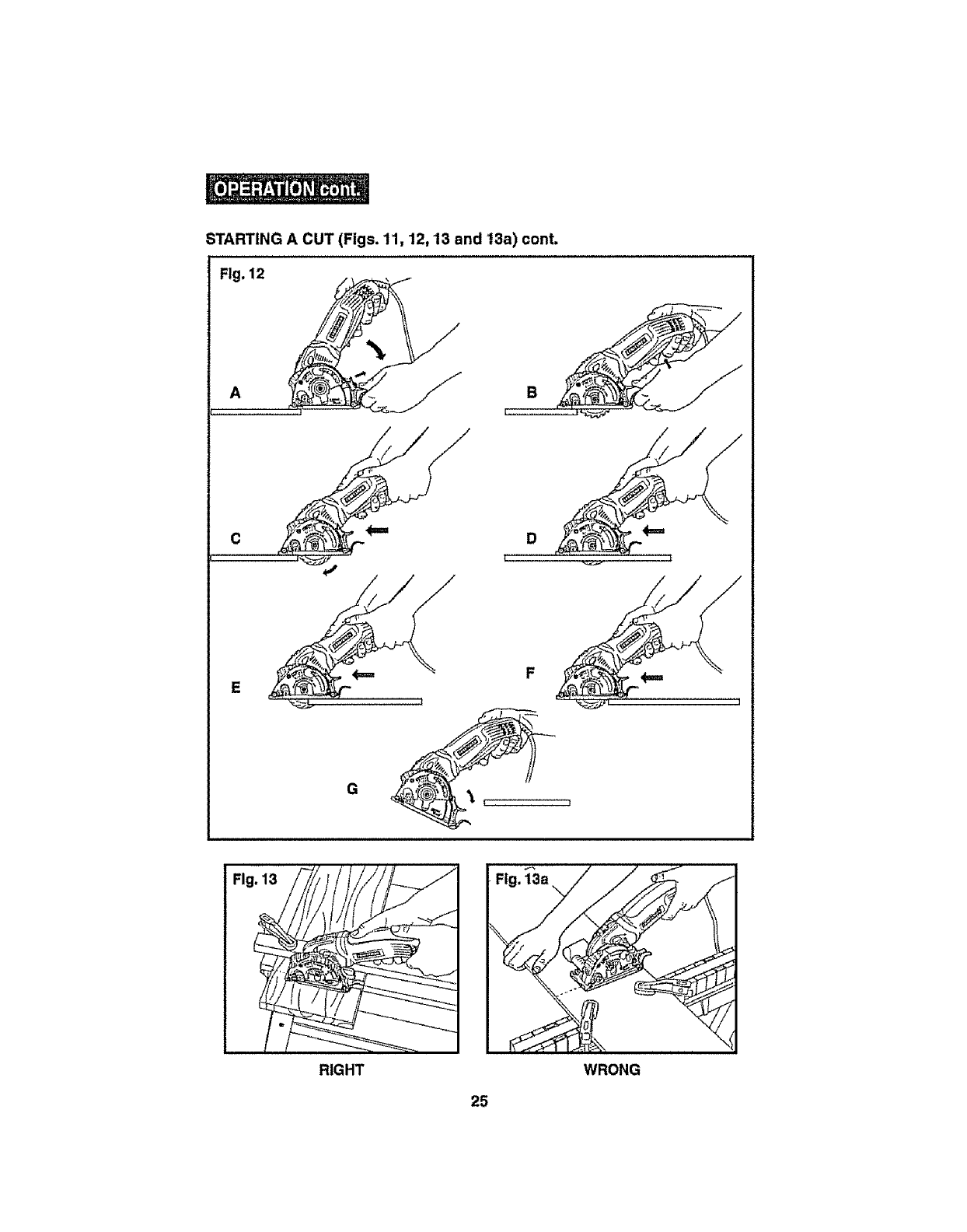
8. Manuallyreleasethe bladeguard
release leverwhile holdingthe finger
lift bracketon the rear of the base
(see Rgo12, A and 13)as you lowerthe
saw's handle andblade to the
selected depth,MAKE SURETHE
BLADEIS NOT MAKINGCONTACT
WITHTHEWORKPIECE.
9_With both hands on the handle, squeezethe tdgger'smoldedfingergripsafety
release "backward"whilesqueezing down onthe paddleswitch to turnthe saw "On".
I0o Let the blade reach fulIspeedBEFORE you enter the workplace, starting your cut.
t !o Pressdown on the saw, keepingthe front of the base flat against the workplece as you
slowly pushthe saws blade intothe workplace(sea Fig. 12, C).
12.Carefully guide the saw through the lineof cut. DO NOT bind the blade Inthe cut;
push the sawbladeforward at a rate where the blade is not laboring.When the cut Is
comptets, release the trigger safety release endpaddle switchand let the blade come
to a complete stop.DO NOTREMOVEthe saw and bladefrom the workplace while the
blade is moving.This could damage your cut (kerf), cause kickback, loss of control, and
resultin serious injury.
t3. When the blade and saw are clear of and removedfrom the workplace (see Fig.12, F),
the lower blade guard and base will be abte to automatically drop down and the blade
guardreleaseleverwilt engagethe upper bladeguard, lockingthe bladeabovethe base
(see Fig.12, G).
_WARNING: ALWAYS maintain proper control of the saw to make sawing I
safer and easier. Loss of control of the sew could cause an accident resulting I
In possible serious injury,
i i i i i ii ii i i
14. ALWAYSuse yoursaw withyour handspositionedcorrectly,one hand operatingthe
triggersafetyreleaseand paddleswitches and the otherhandon the motor
housing/handle,
15. NEVER use the saw with your hands positioned as shown In Fig, 13a,
24
STARTING A CUT (Figs. 11, 12, 13 and 13a) cont.
Fig. 12
A
F
G
Fig. 13
RIGHT
Fig. 13a %
25
WRONG
ToHelpMaintainControl:
1. ALWAYSsupporttheworkplacenearthecut°
2. ALWAYSsupporttheworkplaceso the cutwili be onyourright.
3, ALWAYSclampthe workplaceso it wtlinot moveduring the CUtr,Place the workplace
with the good side down_
NOTE:The good of the workplece the where appearance Important. ]
side is slde Is !
4, NEVER place the sawon the part of the workplace that willfall off whenthe cut Is
made (see Fig 13s).
5, ALWAYSkeep the cord away from the cutting area. ALWAYSplace the cord so it
does not hang up on the workplece when making a cuL
I_WAR NING: tf the cord hangsup on the workplaceduring a cut,release the I
I
trigger switch Immediately.Toavoid Injury unplug the saw and move the cordto !
prevent It from hangingup again.
[_ Using the saw wlth a damaged cord could result In serious |
/
Injury or death. If the cord has been damaged, have It replaced before using J
the saw again.
6. When makinga cut,ALWAYSusesteady,evenpressure.Forcingthe saw causes
roughcutsand coutdshortenthe lifeof the saw orcause Kickback.
L_ CAUTION: This circular saw DOES NOT have the standard retractable
lower blade guard found on standard circular saws. ON THIS saw the lower
blade guard Is an Integral part of the saw's base and only encloses the
blade ABOVE the saw's base. When the desired depth of cut Is set, the
blade Is manually lowered (plunge action) below the lower blade guard and
base assembly to make the cut, This Is done by releasing the blade guard
release lever,
After the cut Is made and the blade clearsthe workplece, the lower blade guard
and base assembly will automatically "drop"down and the blade guard release
lever will engage the upper blade guard and lock In position and the blade will
be ABOVE the base enclosed by the upper and lower blade guard and base
assemblies.
_CAUTION: : Familiarizeyourselfwith this BLADEGUARD SYSTEMand the I
PLUNGEACTION (toweringbladeto desired depth) BEFORE USING!h!s saw.................I
26
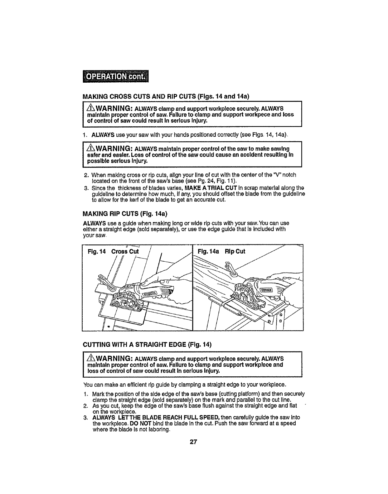
MAKINGCROSSCUTSANDRIPCUTS(Figs.14and14a)
lWARNING: ALWAYSclampand support workplecesecurely.ALWAYS
maintainproper control of saw. Failureto clamp and support workpeceand loss
of control of saw could result In serious Injury.
1. ALWAYSuseyour saw withyour hands positionedcorrectly(see Figs°14, 14a)_
I_WARNING: ALWAYSmaintainpropercontrol of the saw to make sawing
safer andeasier. Lossof control of the saw could cause an accident resultingIn
posslble serious Injury.
2. When making cross or rip cuts, align your line of cut with the center of the '_/" notch
located on the front of the saw's base (see Pg. 24, Fig. 1 t).
3. Since the thickness of blades varies, MAKE ATRIAL CUT In scrap matertal along the
guideline to determine how much, if any, you should offset the blade from the guideline
to allow for the keff of the blade to get an accurate cut.
MAKING RIP CUTS (Fig. 14a)
ALWAYSuse a gulde whenmaking longorwiderip cutswithyoursawoYoucan use
either a straightedge (sold separately), or use the edge guide that ts includedwith
your saw.
Fig. 14a Rip Cut
CUTTING WITH A STRAIGHT EDGE (Fig, 14)
I _WARNING: ALWAYSclampand support workplecesecurely.ALWAYS I
I
maintainproper controlof saw. Failureto clampand support workplaceand I
lossof control of saw could result In serious injury.
Youcan make an efficient rip guide by clampinga straight edge to your workpleceo
t. Markthe positionof the stdaedge of the saw's base (cutting platform) and then securely
clamp the straight edge (sold separately) on the mark and parallelto the cut line.
2. As you cut, keep the edge of the saw'sbase flush against the straight edge and flat
on the workplace.
3. ALWAYS LETTHE BLADE REACHFULL SPEED,then carefullyguide the saw into
the workp]eceoDO NOTbindthe blade inthe cut.Pushthe sawforward at aspeed
wherethe blade Is notlabortng_
27
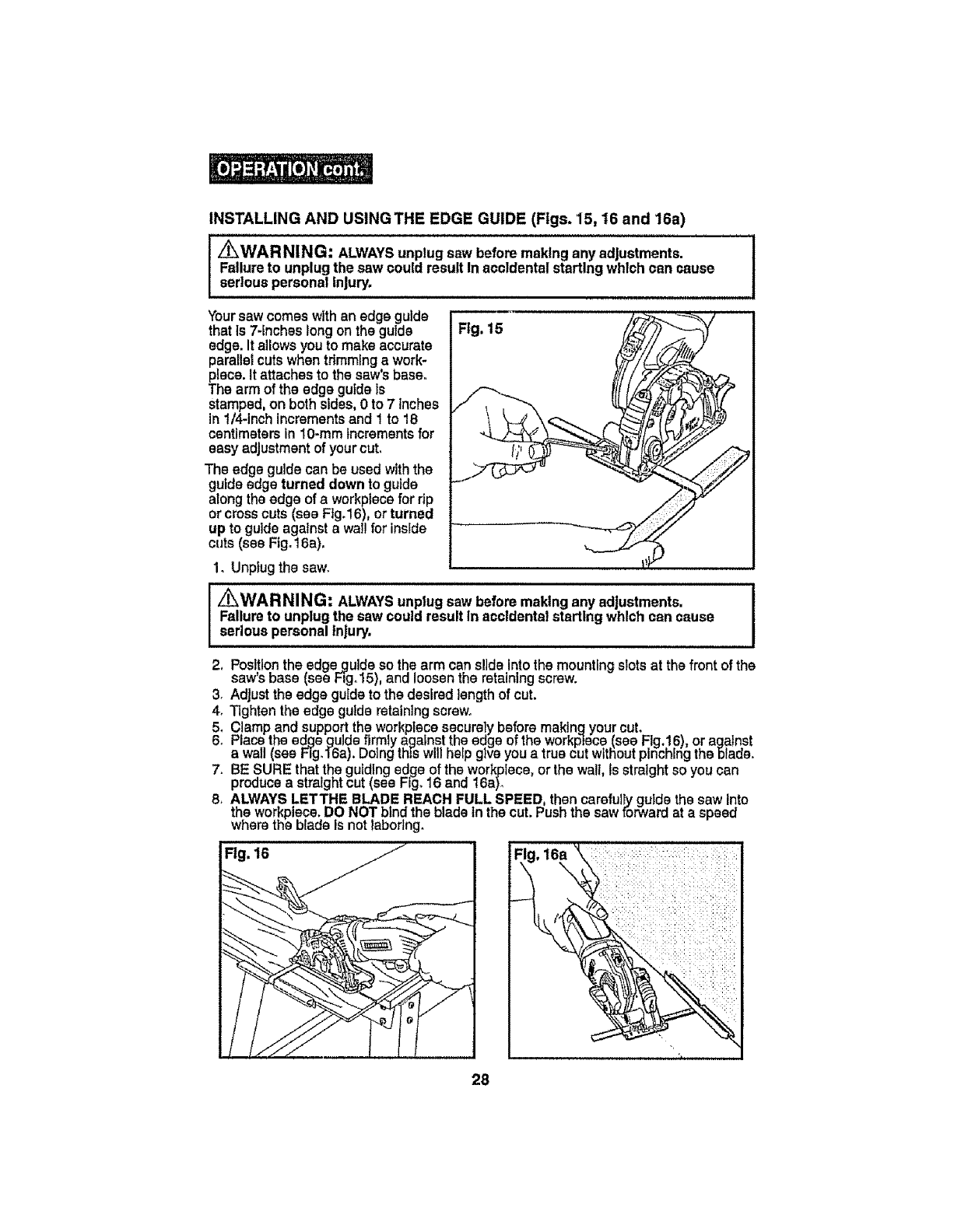
INSTALLINGANDUSINGTHEEDGEGUIDE(Figs.15,16and16a)
z_WARNING: ALWAYSunplugsaw before making any adjustments. I
Failureto unplugthe saw could result Inaccidental startingwhich can cause !
seriouspersonal injury,
Yoursaw comeswith an edge guide
that is 7-fncheslong on the guide
edge. It allows you to make accurate
paratletcuts when tdmmfng a work-
piece. It attaches to the saw'sbase..
The arm of the edgeguide Is
stamped, on both sides, 0 to 7 inches
in 1/4-Inchincrementsand 1 to 18
centimeters in 10-mm increments for
easy adjustment of your cut,
The edgeguide can be used with the
guide edge turned down to guide
along the edge of a workplace for rip
or cross cuts (see Ftgo16),or turned
up to guide against a wal! for inside
cuts (see Fig.16a),
1. Unplug the saw.
Fig. 15
/_ WAR NING: ALWAYSunplugsaw before making any adjustments. I
Failureto unplugthe sawcould result In accldentalstarting which can cause I
seriouspersonal injury,
2, Positionthe edge guide so the arm cans!]de Intothe mounting slots at the front of the
saw'sbase (see Fi-go15),and loosen the retaining screw.
3. Adjust the edge guide to the desired length of cut.
4. Tighten the edge gulde retaining screw.
5, Clampand supportthe workplace securely before maktn.qyour cut,
6. Race the edgeguide firmly against the edge ofthe workplace(see Fig.16), or against
a wall (sea Hg.16a). Doing thi-swill help give you a true cut without pinching the blade.
7. BE SURE that the guid!ngedge of the workpfece, or the wall, is stralght so you can
produce a straight cut (see Fig°16 and 16a).
8. ALWAYSLETTHE BLADE REACHFULL SPEED, then carefuiIy guide the saw into
the wort_plece.DO NOT .blndthe blade in the cut. Push the sawforward at a speed
where the blase is not larJonng.
Fig. 16
,,,III,IL,I ILL I LJlJ J !ILL J'J'J LL IL
28
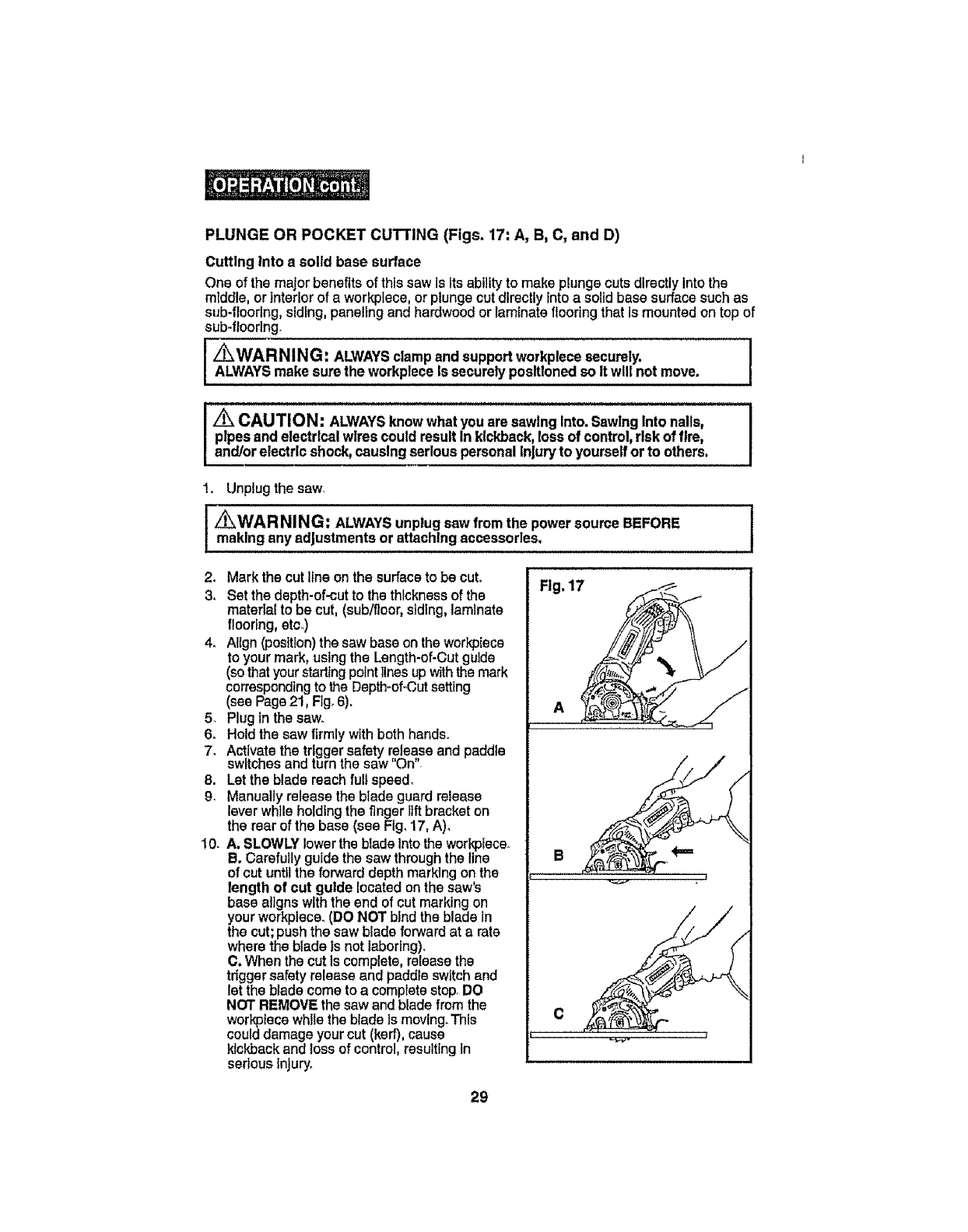
PLUNGE OR POCKET CUTTING (Figs. 17: A, B, C, and D)
Cutting Into a solid base surface
One ofthe major benefits of thissawis Its abilityto make plungecuts directly Into the
middle, or Interiorof a workplace, or plunge cut directly Intoa solid base surfacesuch as
sub-flooring, siding, panelingand hardwoodor laminateflooringthat Is mounted on top of
sub-flooring.
[ Z_WARNING: ALWAYSclampandsupport workplecesecurely. I
ALWAYSmakesurethe workpleoeIs securelyposltlonedso Itwlfi not move.
IZ_CAUTION: ALWAYSknowwhat you are sawing Into.Sawlng Into nalis, I
I pipes andelectricalwirescouldresult In kickback,ross of control,riskof fire, I
] and/or electric shock,causingseriouspersonal Injury to yourselfor to others. I
1. Unplug the saw.
/_WARNING: ALWAYSunplugsawfrom the powersource BEFORE
makingany adjustmentsor attaching accessories.
2. Mark the cutline on the surface tobe cut.
3, Set the depth-of-cut to the thickness of the
material to be cut, (sub/floor,siding,laminate
flooring, etco)
4. Allgn (position)the saw base on the workplace
to your mark, using the Length-of-Cutguide
(sothat yourstarting pointlines upwiththe mark
correspondingto the Depth-of-Cutsetting
(see Page21, Figo6).
5_ Plug inthe saw.
6o Hold the saw firmly with both hands.
7. Activate the trlgger safety release and paddle
switchesand turn the saw "On".
8. Let the blade reach full speed,
9. Manually release the blade guard release
leverwhile holdlng the fingerlift bracket on
the rear of the base (see Fig. 17, A).
!0. A, SLOWLYlower the bladeIntothe workplace.
B. Carefully guide the sawthroughthe line
of cut untl!the forward depth marking or}the
length of cut guide located on the saw's
base aligns withthe end of cut marking on
your workplace. (DO NOT bind the blade in
the cut;push the saw blade forward at a rate
where the blade is not laboring).
C. When the cut Is complete, release the
trigger safetyrelease and paddle switch and
letthe bladecome to a completestop, DO
NOT REMOVEthe saw andblade from the
workplace while the blade Ismoving.This
could damage your cut (kerf), cause
kickbackand loss of control, resulting In
serious Injury,
Flg. 17
29
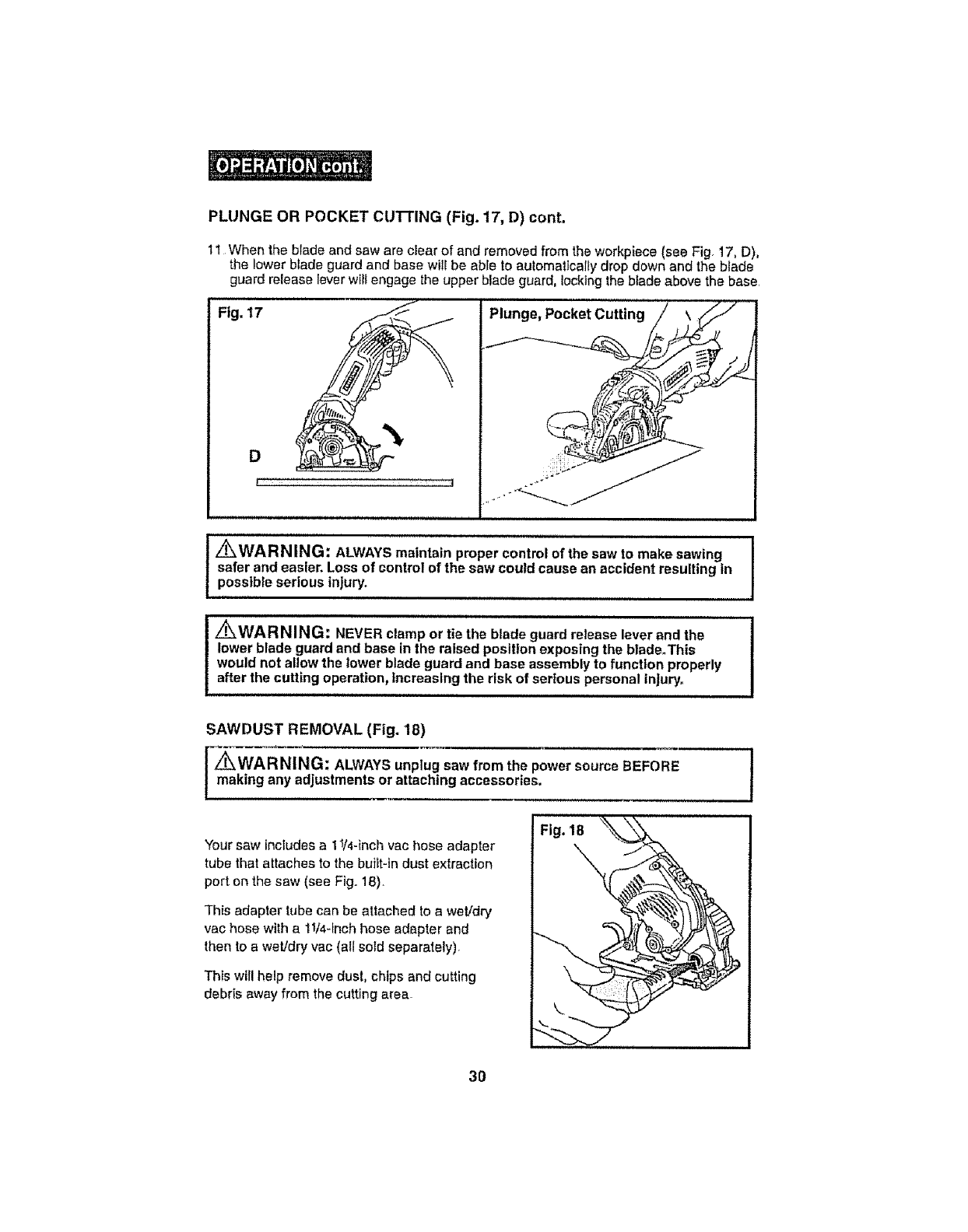
PLUNGE OR POCKET CLI'i-I'ING (Fig. 17, D) cont.
11 When the blade and saw are clear of and removed from the workpiece (see Fig 17, D),
the lower blade guard and base will be able to automatically drop down and the blade
guard release lever will engage the upper blade guard, locking the blade above the base.
Fig. 17 f
D
i : i
Plunge, Pocket Cutting
! _WARNING: ALWAYS maintain proper control of the saw to make sawing I
I
safer and easier. Loss of control of the saw could cause an accident resulting in I
possible serious injury.
i i, i i ,,lll,ll,l,,i,illl, iii
Z_WARNING: NEVER clamp or tie the blade guard release lever and the
lower blade guard and base in the raised position exposing the blade.This
would not allow the lower blade guard and base assembly to function properly
after the cutting operation, increasing the risk of serious personal injury.
SAWDUST REMOVAL (Fig. 18)
z_WARNING: ALWAYS unplug saw from the power source BEFORE
making any adjustments or attaching accessories.
Your saw includes a 11/4-inch vac hose adapter
tube that attaches to the built-in dust extraction
port on the saw (see Fig. 18).
This adapter tube can be attached to a wet!dry
vac hose with a 11/4-inch hose adapter and
then to a wet/dry vac (all sold separately).
This will help remove dust, chips and cutting
debris away from the cutting area_
Fig. 18
30
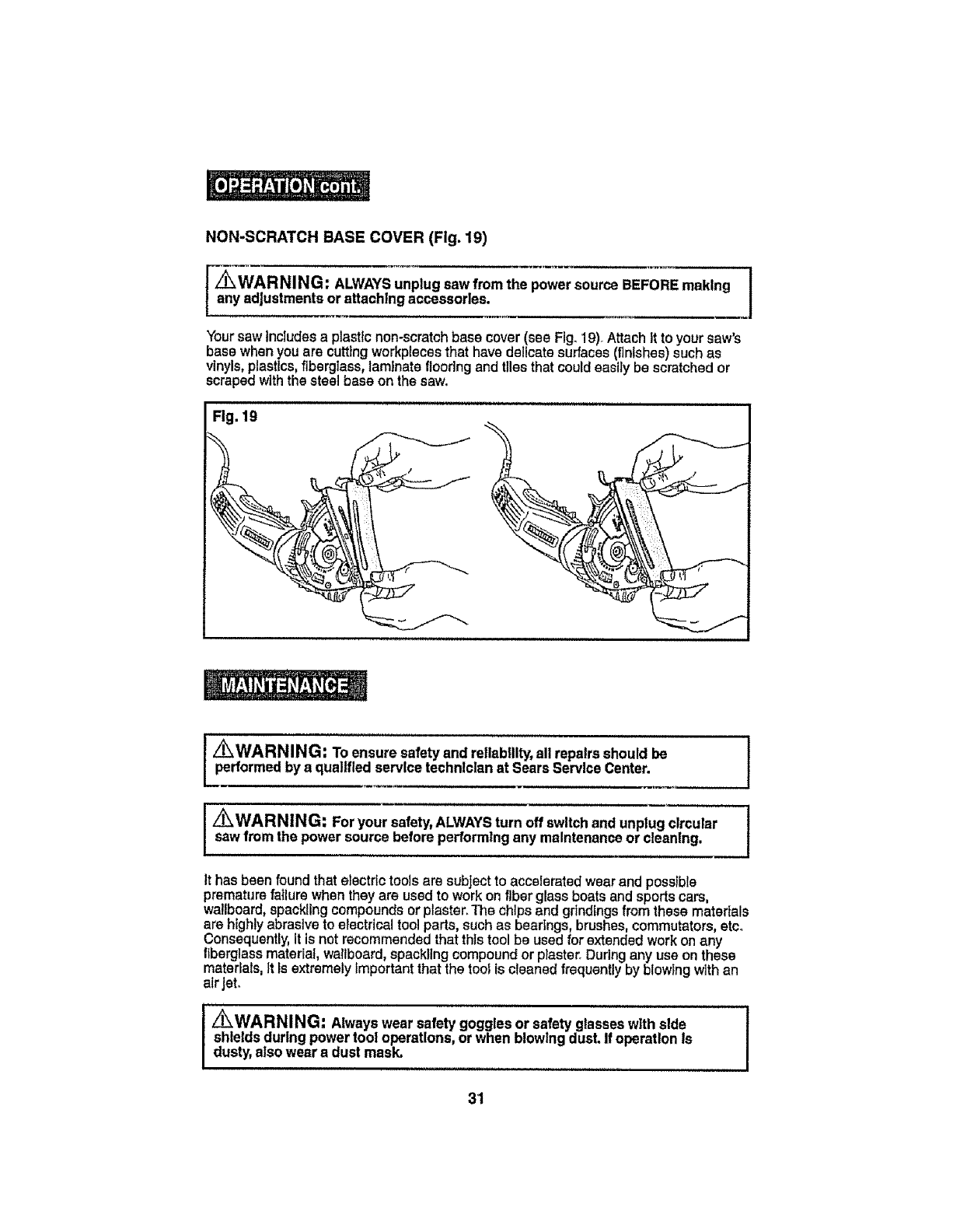
NON-SCRATCHBASECOVER(Fig.19)
Z_ WAR NING: ALWAYSunplug sawfrom the power source BEFOREmaking
any adjustmentsor attachingaccessories.
Yoursaw tnctudesa ptastlc non-scratch base cover (see Fig_19)°Attach It to your saw's
base when you are cutting workptecesthat have delicate surfaces (finishes) such as
vinyls, plastics, fiberglass, lamlnate flooring and tiles that could easfiy be scratched or
scraped with the steel base on the saw.
Fig. lg
[Z_WARNING: To ensure safetyand retlablllty,all repairs should be
performedby a qualified servicetechnician at Sears ServiceCenter. f
I_WARNING: For your safety,ALWAYSturn off switchand unplugcircularsawfromthe power source before performingany maintenanceor cleaning, I
It has been found that etectrtctoolsare subject to accelerated wearand possible
prematurefailure when they are used to work on fiber glass boats and sports cars,
wallboard,spackling compounds or plaster.The chips and gdndings from these materials
are highly abrasive to electrical tool parts, such as bearings, brushes, commutators, etco
Consequently,It is not recommended that this tool be used for extended work on any
f_berglassmaterial, wallboard, spackllng compound or piaster. During any use on these
materials,It is extremely importantthat the tool is cleaned frequently by blowing with an
air jet.
iz_WARNING: Alwayswear safety goggles or safety glasseswith side
shieldsduring powertool operations,or when blowingdust, if operation Is
dusty,alsowear a dust mask,
3'1
ROUTINE MAINTENANCE
/_WARNING: DO NOTat any time let brakefluids,gasoline,petroleum-
basedproducts,penetratingoils, etcocome In contactwith plastic parts.
Chemicalscan damage, weaken or destroyplastic,which mayresult In serious
personal Injury.
I,IU,PlIIILUl..............................,ll,,I,,,,,, ,,111 , I, I
Periodic maintenanceallowsfor long life and trouble-free operation.Acleaning,
lubrication and maintenance schedule should be maintained. As a common preventative
maintenance practice, foilow these recommended steps:
,/_WARNING: For your safety,ALWAYSturn off switchand unp|ug clreular !
sawfrom the power source before performingany maintenanceor cleaning.
1. When workhas been completed,cleanthe toolto allow smooth functioning of the
tool overtime..
2. Usa clean damp cloths to wipe the tool.
3o Check the state of allelectricalcables.
4. Keepthe motor alr openings free from o11,grease and sawdust or woodchips, and
store tool in a dry place.
5_ Be certain that ali moving partsare weFIlubricated, partlcular]y after lengthy exposure
to damp and/or dirty conditions.
LUBRICATION
All of the bearings inthis tool are lubricated witha sufficlentamountof hlgh-grade
lubricant for the lifeof the tool under normal operating conditions.Therafora, no further
lubrication is required°
32
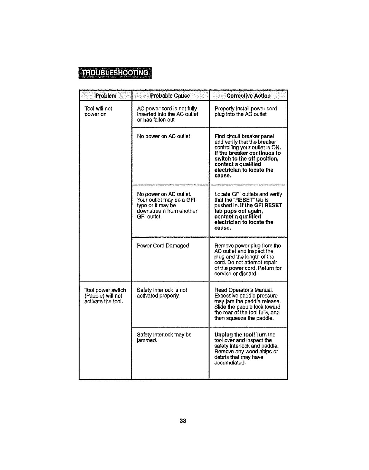
Tool wlll not
power on AC power cord is not fully Properly Install power cord
Inserted Into the AC outlet plug Into the AC outlet
or has fallen out
No power on AC outlet Find circuit breaker panel
andverify that the breaker
controlling your outlet Is ON,
if the breaker continues to
switch to the off position,
contact aqualified
electrician to locatethe
cause,
No power on AC outlet. Locate GFI outlets and verify
Youroutlet may be a GFI that the "RESET_'tab is
type or it may be pushed In.If the GFI RESET
downstream from another tab pops out again,
GFI outlet, contact aqualified
electrician to locatethe
cause.
Tool power switch
(Paddle) will not
activate the tool,
PowerCordDamaged
SafetyInterlock Isnot
activated properly.
Safety Interlockmay be
Jammed°
Remove powerplug from the
AC outlet and Inspect the
plug and the length of the
cord. Do not a_empt repair
of the power cord, Return for
serviceor discard°
Read Operator's Manual.
Excesslve paddle pressure
mayjam the paddle release.
Slide the paddle lock toward
the rear of the tool fully,and
then squeeze the paddle,
Unplug the tooll Turnthe
tool overand Inspectthe
safetyInterlock and paddle.
Removeany woodchipsor
debris that may have
accumulated.
33
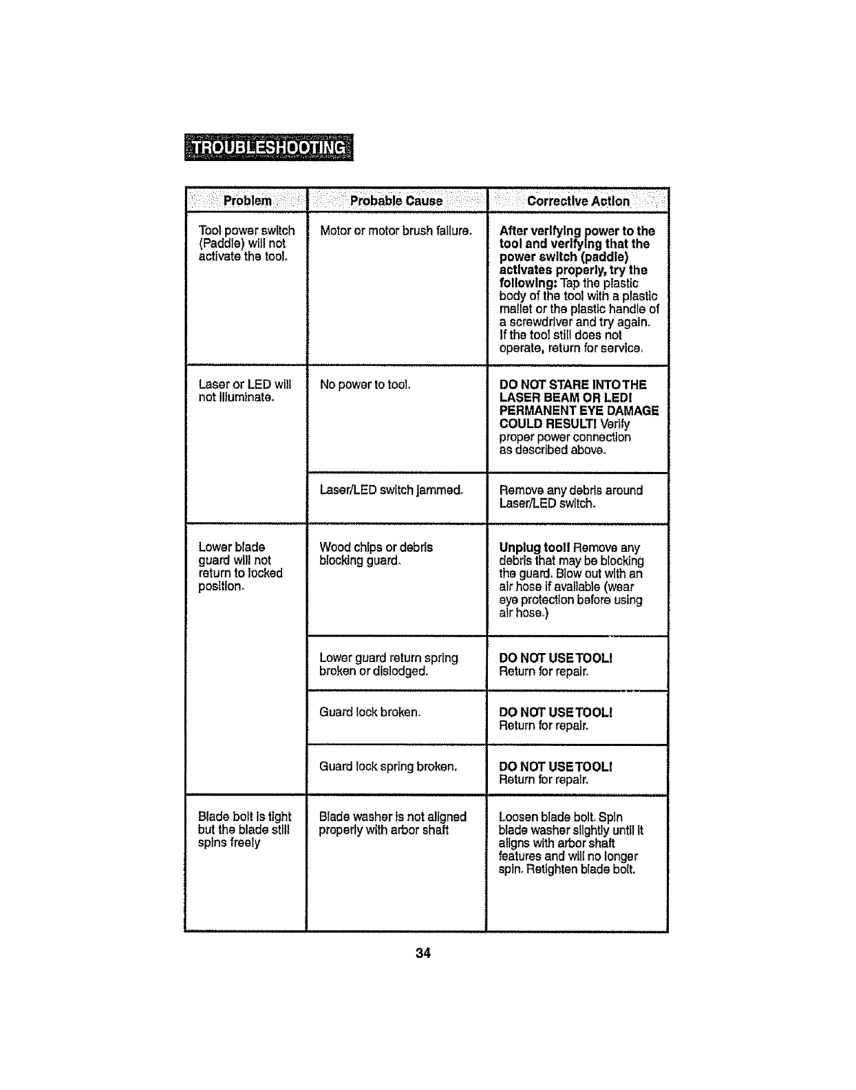
Tool powerswitch
(Paddle) will not
activate the tool.
Laser or LED will
not Illuminate,
Lower blade
guard will not
return to locked
posltlon_
Blade bolt is tight
but the blade sttll
sp_nsfreely
Motor or motor brush failure_
No power to tool
LasedLED switch Jammed,
Woodchfps or debds
blockingguard.
c0rrectlveAction :. :
After verifying power to the
tool and verifying that the
power switch (paddle)
activates properly,try the
following: Tap the plasttc
body of the tool with a plastic
mallet or the plastic handle of
a screwdriver and try again.
If the tool stilldoes not
operate, return for service,,
DO NOTSTARE INTOTHE
LASER BEAM OR LEDI
PERMANENTEYE DAMAGE
COULD RESULTIVedfy
proper power connection
as describedabove.
Removeany debrisaround
Laser,q.EDswitch.
Unplugtooll Remove any
debris that maybe blocking
the guard. Blowout withan
alr hose if avallaNe(wear
eye protection before using
air hose°)
Lowerguard return spring DO NOTUSETOOL!
brokenor dislodged. Return for repair.
Guardlock broken. DO NOTUSETOOLI
Return for repair.
Guardlock spring broken.
Bladewashertsnot aligned
properlywith arbor shaft
DO NOT USETOOLI
Returnfor repair.
Loosen bladebolt.Spin
bladewasherslightly untilR
aligns with arborshaft
featuresand will no longer
spin.Retightenblade bolt.
34

/_WARNING: The use of attachmentsor accessoriesthat are not ]
recommendedfor this tool might be dangerousand couldresult InseriousInjury° ]
Sears and otherCraftsman outlets have aCraftsman 3-tn°dlamond grit steel blade
(9-61273) available for cutting ceramic and marble ttie up to 318-tn.thick with this saw.
Replacement bfadesare alsoavailable forthe Craftsman@3-In.20 tooth carbide-tipped
steel general purpose blade (9-61272) which comes with the saw,
Searsand other Craftsman outletshave alarge assortment of clamps,eomblnatlon
squares, straight edges,work tables, and sawhorsesto helpyou withall your sawtngneeds.
Vlstt your local Sears storeorother Craftsman outletsor shopsears.com/craftsman.
3S
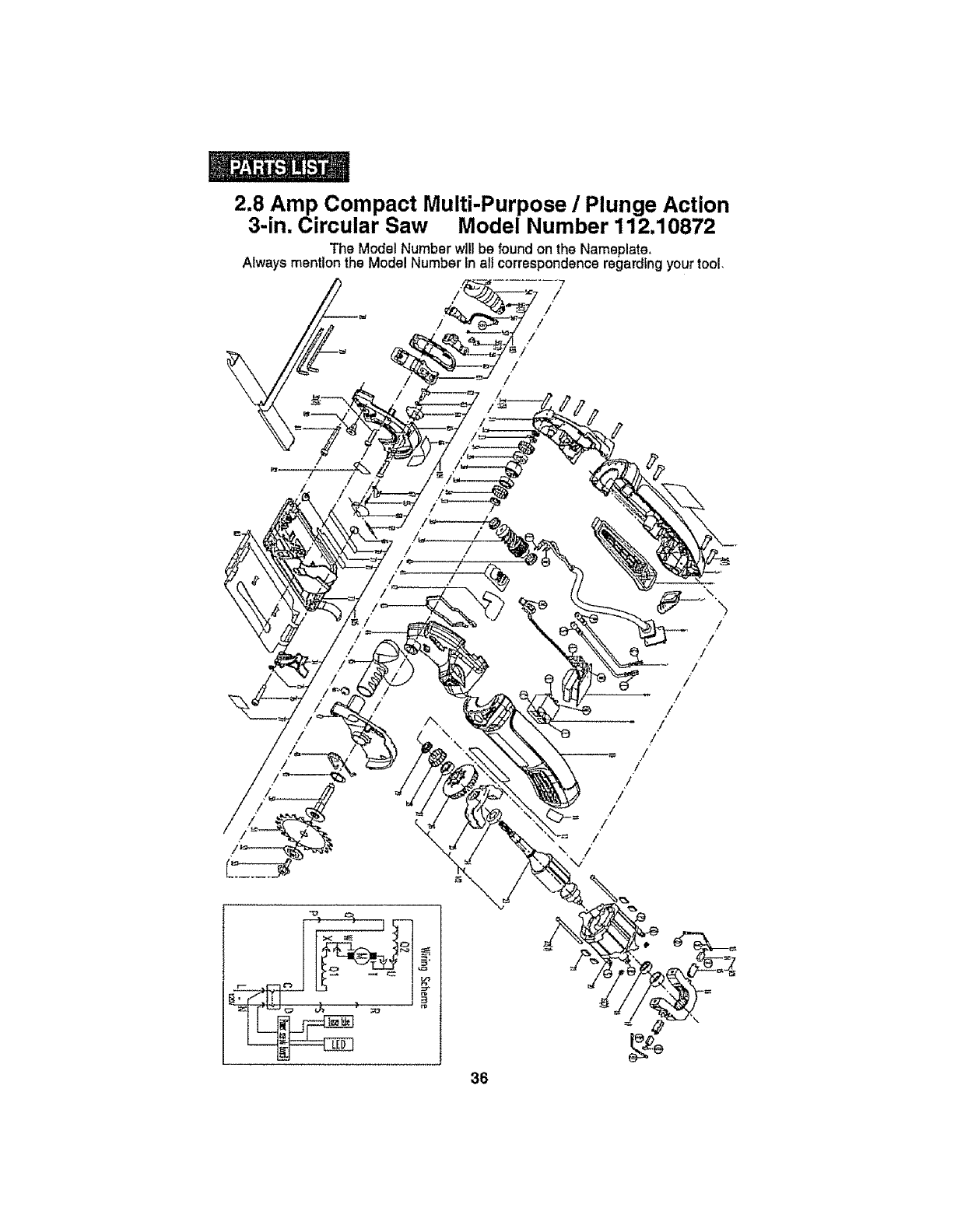
2.8 Amp Compact Multi-Purpose /Plunge Action
3-in. Circular Saw Model Number 112.10872
The Model Number willbe found on the Nameplate.
Always mention the Model Number In all correspondence regarding your tool.
/
/
/
/'
!
36
/
/
/
/
/
/
/
/
./
/
/
I
'_/

2.8 Amp Compact Multi-Purpose /Plunge Action
3-in. Circular Saw Model Number 112.10872
The Model Number will be found on the Nameplate,
Always mention the Model Number fn ail correspondence regarding our tool.
Parts No, Part Description
.amNo.
1
2
3
o
4
5
6
7
8
9
10
16
300801
3oo3_9 I
3780015
601743
included
included
Inc{uded
Included
601749
included
included
included
Rated Label
Se!f tapping Screw ST4.2X 16
R!pht hous!ng
Tr+gger Unit Assembly
Cover
revolve-button
Compression Sprtng
Knob holder
Power Cord Assembly
Cable Protector
inner Line 120 (b!ue)
inner wire 60 (brown)
Qty+
t
4
1I
1
t
1
1
I
2
2
11 300744 . PCB Set .1
12 300766 Switch 1
13 3780014 Left Housing 1
i4 inctuded Labet? 1
15 included Brand LabeI 1
101 300767 Carbon brush set 2
,17, included Carbon Brush Assembty 2
18 fncluded Brush HoIder 2
102 601744 MOtOr Assemb!_ 1
19 included Rear Support, 1
Be!! bearing 619(6+2Z
Nut M3
Slator Assembly_
Cushion
Screw Washer Assembly M3x45
Armature
Bali bearln_ 61800+2Z/C3
Front Support
Fan
1
2
21 included
22 included
23 included
24 included
25 included
26 Enciuded
27 included
28 'fnciuded '
29 included
1
4
2
1
1
3o , included' ,Ball bearing 619/9+2Z , ' 1 ,
31 included Tolerance Ring 1
32 fnduded _C0170 TC 9x17x4 1
33 300768 Screw M4X20 7
34 .300751 .Gear Case Cover . 1
35 300799 Sealing 10675 TCBx15x4 1
36 300796 E Rag 5 1
37 300753 Tole[snceB!n_ 2,
38 300795 _ 628/9+2Z]C3 2
39 300793 Worm gear 1
40 300798 Sealing 1
41 300740 Tolerance Ring ' 1
1.601750 . Worm Shaft Assembly !
42 , fncluded , Ball bearing 634t2Z/C3 1
43 Included Worm shaft 1
44 Included Gear 1
45 included Bali bearing 624+2Z 1
46 included Tolerance Ring ___1
37

2.8 Amp Compact Multi-Purpose /Plunge Action
3-in. Circular Saw Model Number 112.10872
The Model Number willbe found on the Nameplate.
Always mention the Model Number inall correspondence regarding your tool,
ttem No. Pads No.
47 3780024
48 3780019
49 300797
50 300752
51 3780,D25..........
52 300781
53 300761
54 300764
55 300773
55 300794
57 300900
58 300750
59 300749
103 601747
60 Included
61
62
83
64
65
66
67
t04
68
69
70
71
included
....!,n_!ud_d,
included
Included
Included
included
inctuded
601748
included
included
included
included
72 Included
73 included
74 included
75 included
88 included
105 501753
76 included
77 included
78 included
79 included
80 included
81 included
82 Included
..........8,3.... Included
84 300774
85 300776
66, 300777
87 300788
89 3780029
90 300783
oty.
I
1
1
i
1
1
t
t
1
1
3
1
Part Description ...................
Switch Level
SlideBu[ton
Seat gasket ..............
Gear Housing
Dust Tube
,,NutM4
Lower Guard
Torsoni_l spr!ng
Retaining Ring 17-A
splndte
Saw Blade 1
Ou!e,r Ffange I
Screw 1
Laser Unit Assembly 1 .....
Laser Cover ?1
Self Tapping Screw ST2.2x8
Laser and LED Unit
Screw M3x4 t
Setf Tapping Screw ST2.x6 2
Laser Tube Bracket 1
Bracket 1
Laser_'_k'_t' 1
Upper Guard Assembly 1
Pin shall 1
SpringWash,e,r, , , 1
Adaptor 1
Upper Guard 1
Label ? 1
Pointer 1
Cem,,Bu,t!,0n !
Spring Pin 2,5×18 .................. 1
Label ?
Base Assembly 1
Label ? 1
Screw M5x6 I
Label ?I
Base we,ldtng Unll 1
Support Pin 1
Boil I
Ii' 'Scate Label? 1
Assembly .......... 1
Spanner 2
,,, Screw .................................. 1
Bolt I
Prolector Board 2
Owners Manual I
38

39

40
Manual del Operador
Sierra circular de
3 pulgadas
2.8 Amp compacto
multiuso/de corte en profundidad
con LaserTracTM
Modelo No.
112.10872
DOBLE AISLAMIF._TO
Z_ PRECAUCION: Lea, entienda y siga
todas las Normas de Seguridad e Instrucciones
de Operaci6n en este Manual antes de usar
este producto,
Sears, Roebuck and Co.,
Hoffman Estates, IL 60179 U.S.A.
Vlslte nuestra pdglna Web Craftsman®:
www.seers.com/craftsman
•GARANTfA
•SEGURIDAD
•DESEMPACADO
•DESCRIPCi6N
•OPERACl6N
•MANTENIMIENTO
Garant,ra.................................................................................... P_.gina 42
Sfmbolos de seguridad ....................................................... P_gina 43
Instrucdones de seguridad .................................................. P_.ginas 44 - 51
Glosario de T_rminos ......................................................... P_ginas 51 - 52
Desempacado ................................................................... P_gina 53
DescripciSn ............................................................................... P&ginas 54 - 55
Operaci6n .................................................................................. P&ginas 56 - 71
Mantenimiento ........................................................................... P_ginas 71 - 72
Resoluci6n de problemas .......................................................... P#.ginas 73 - 74
Accesorios ................................................................................. P_gina 75
Partes de repuesto .................................................................... P,'_ginas 75 - 78
Nt_imerosde Tel6fono de Partes de Repuesto de Sears .......... Cubierta posterior
UN A_O COMPLETO EN HERRAMIENTAS CRAFTSMAN ®
Siesta Herramienta Craftsman falta debido a defectos en los materiafes o
mano de obra entro un aSo desde la fecha de compra, REGRESELA A
OUALQUIER TIENDA SEARS O CENTRO DE PARTES YRESPARACION
U OTRATIENDA CRAFTSMAN EN LOS ESTADOS UNIDOS PARA UNA
REPARACION GRATIS (O REEMPLAZO SI ES IMPOS|BLE
REPARARLA).
Esta garantia no incluye partes desechables tales como I_mparas, pilas,
puntas u hojas
Si este producto Craftsman se utiliza para fines comerciales o de alquiler,
esta garant{a aplica s61o para 90 d{as desde la fecha de compra.
Esta garantia le otorga derechos legales especfficos yes posibte que
usted tenga otros derechos, los cuales varfan de un estado a otro.
Sears, Roebuck and Co, Hoffman Estates, IL 60179
1GUARDE ESTAS INSTRUCCIONES!
ILEA TODAS LAS INSTRUCCIONESI
Z_ ADVERTENCIA: Algun polvo generado por el use de herramtentas
el_ctricas conttene qufmicos conocidos por el estado de California pot
causar cancer y defectos de nacimiento u otros defectos para la
reproduccibn.
42
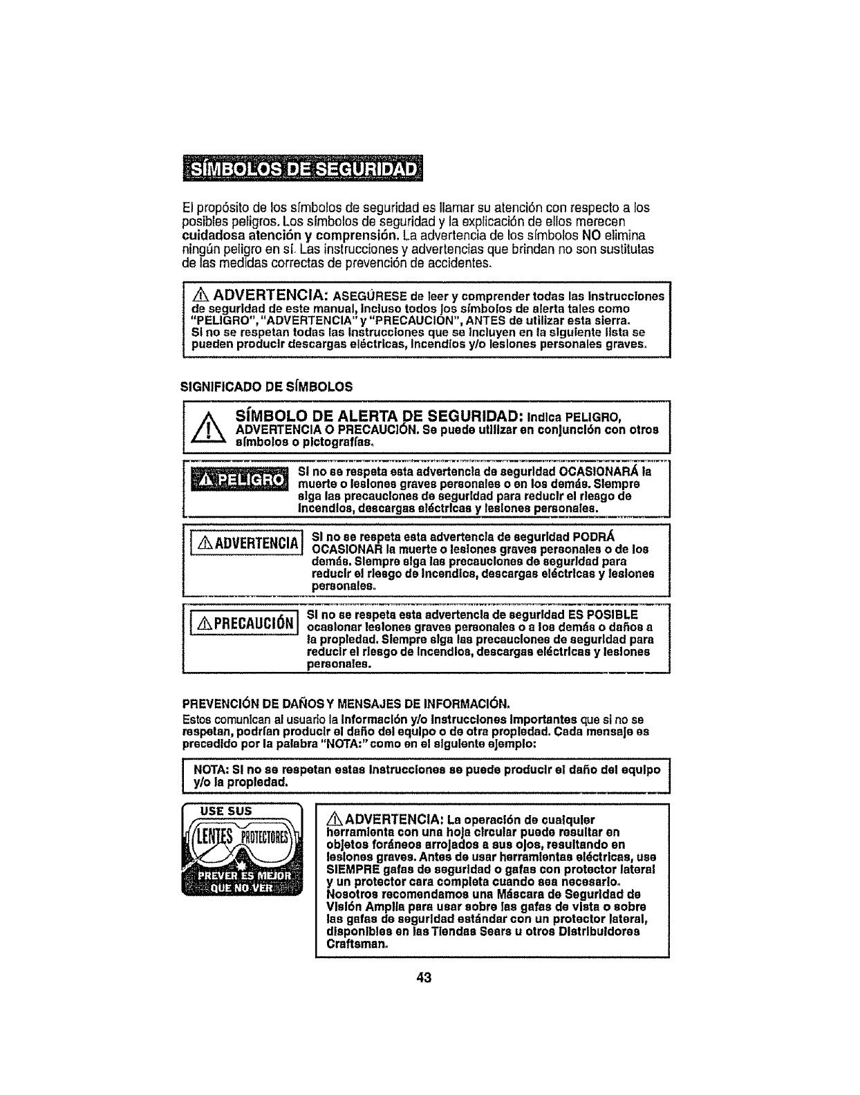
El prop6sito de los s]'mbolosde segufidad es llamar su atenci6n con respecto a los
posibles peiigros. Los s_mbolosde seguridad y la explicaci6n de ellos merecen
cuidadosa atenci6n y comprensi6n, La advertencia de los sfrnbolos NO elimina
ningOnpeligro ens[, Las instrucciones y advertencias que brindan no son sustitulas
de las medidas correctas de prevenci6n de accidentes.
/_ ADVERTENCIA: ASEGURESE de leer y comprender todas las Instrucctones
de segurldad de este menus!, Incluso todos joe, simbolos de alerts tales como
"PELIGRO", "ADVERTENCIA ' y "PRECAUCION ', ANTES de utilizar esta sierra.
Sl no se respetan todas las Instrucclones que se lncluyen en la slgulente lists se
pueden produclr descargas eldctricas, Incendlos y/o leslones personales graves,,
SIGNIFICADO DE SfMBOLOS
//_ SfMBOLO DE ALERTA DE SEGURIDAD: tndlcs PELIGRO,ADVERTENCIA O PRECAUCION. Sa puede utilizer en conjuncl6n con otros
sfmbolos o plctograffas,
SI no ea respsta esta advertencla de segurldad OCASIONAR_, la
muerte o leslones graves personales o en los demds. Slempre
alga las pracauclones de seguddad para reduclr el desgo de
Incendloa, desaargaa el6ctrlcas y lealones personalea,
]Z_ I SI no se respeta esta advertencla de segurldad PODRA
ADVERTENCIA
IOCASIONAR la muerte o leslones graves personales o de los
demde. Slempre alga las precauclones de seguddsd para
reduclr el riesgo de Incandlos, descargas el6ctrlcas y leslones
personales°
] SI no se respeta esta advertencla de segurldad ES POSIBLE
AkPRECALICi6N, ocaslonsrleslonesgravespereonaleso a losdemdso dal_osa
ia propledad. Slempre slga Iss precauclones de segurldad pars
reduclr el rlesgo de Incendlos, descargas eldctrlcaa y lealones
pemonalea.
PREVENCI6N DE DAI_IOSY MENSAJES DE INFORMACI6N,
Estoscomuntcan al usuartola Informacl6n y/o Instrucclones Importantes qua si no sa
respetan, podrfan produclr el dafio dsl equlpo o de otra propledad. Cads mensaJe es
precedldo pot la palabra "NOTA:'eomo en el slgulente eJemplo:
NOTA: SI no se reapetan estas Instrucclonea ss puede produclr el de_o dsl equlpo
y/o la propledad,
USE SUS Z_ ADVERTENCIA: La operacl6n de cuelqular
herramlenta con una hojs ctrcular puade resulter en
obJetos fordneos arroJados asue ojos, resultando sn
leslones graves. Antes de user herramlentas eldctrlcas, use
SIEMPRE gafas de segurldad o gsfes con protector lateral
y un protector cara complete cusndo sea necesarlo,
Nosotma recomendamos una Mdscara de Seguddad do
Vlsl6n Amplls pars user sobre fee galas de vista o sobre
las gafas de aegurldad estdndar con un protector lateral,
dlsponlbles sn lss Tlendas Sears u otros Dlstrlbuldores
Craftsman_
43
1
Ak ADVERTENCIA: ASEGORESE de lear y entendar todas las Inetrucclones en |
eats manual antes de user este sierra circular. No eagulr todas lee Inatrucclones 1
podrfa reaultsr an sxpsslcl6n aradlacl6n palfgrosa, daacargas cicatrices, Incendlo
ylo leslonea personalss graves.
PRECAUCIONES DE SEGURtDAD PARA EL USO DE LASERES
Esta sierra circulareuenta con una luz Idser tntegradaoEl Idser es de! ttpoClass Ilia y smite
una energfa de aaltda de m_lmo 2.SmW y 635-665nm de Iongitudde ondaoEetoa Ideates
normalmenta no representanun ps!tgro5price° Sin embargo. NO mire directamenteal rayo.
ya qua podrfa ocsslonar csguera per dsatelto.
PRECAUCI6N: La stgulenta etlquata aa encuentra en su W'':.=l
lU_AClbH L_J= NO M_
hsrramlenta. La mlsma Indlca qua is sierra emits luz _._,_,_ /
Idser. ASEGORESE de le ublcacl6n de la luz Idser cuando _-m- =_,=_.._._, =_.., /
usa Is sierra. ASEGORESE SIEMPRE qua todo observador ._."_',o.o..o."_._..=t=...o.o._=
sn ta csrcanfa dal use eat6 conclente de los pallgros de _.,._- ...,..=_._,.
mlrar dlrectaments al I_asr. \ _ _'.'*=._-._- !
z_ ADVERTENCIA: LUZ LASER. RADIACION LASER. Evlte la Exposlcl6n Directs
a Ice OJoe.NO mire flJamsnte al rays. $61o enclenda el reyo Idser ¢uando la plaza de
trebsJo se encusntm sobre le sierra. Ldser Class Ilia.
z_,ADVERTENCIA: El use de controlea, aJustss o realizer proaedlmlantos
dlstlntos a los especlflcados sn eats manual pedrfan reaultar an expoalel6n a
radlacl6n psllgrosa.
ADVERTENCIA: El use de Instrumantoe 6pticos tales come, entre otros,
talascoplos o dlspoeltlvoa de nlvel para vsr el rayo I_ssr Incremsntar_ el rtssgo
pare los ojos,
1. NO retire nl rompa nlnguna de las atlquetas del producto. Rsttrar las stlquetas del
producto Increments el rlesgo de exposlcl6n ala radlacl6n ldsar.
2. El rayo idser puade set dafifno pars los ojos. SIEMPRE evita is exposlcidn directs a los
ojos. NO mire directamente a la abertura de salida del rayo t_ser durante la opsrac tSn_NO
proyecte el rayo Idser dirsctamente en los oJosde los demds. Encienda el Idser SOLO
cuanda vays a reaUzar cortes°
3. El I.-tseren la slerrano es un juguete. SIEMPRE mantenga el rayo fuere del alcance de los
niSos. La luz Idser emltida per este dfsposfttvoNUNCA debe dlrlgtrsadlrectamente a
persona alguna per motive alguno.
4oASEGURESE ds qua el rayoldsar est_ apuntado ata plaza de trabaJo(telcome madera o
superficies dsperas) qua no tangs una superftc_e reflactanta.
5_NO use el I_,ssrsabre superficiestales come I_mlnas de scare qua tsngan superficies
bdllantss y raflectantes. La superficfe briliante podria reflejar el rayo de vuelta af operador,
Tangs presents qua la luz del l_ser qua so refleja en un espsJo u otra superftcte reflectante
podrta tambl_n ser peligrosao
6. SIEMPRE apague el reyo I_ser cuando no io use. Dejar Is herremienta encsndtda
tnoremsnta al riesgo de qua alguten Inadvertldamente mire dlreotaments al rayo I_ser,
,4_PRECAUCION: SIEMPRE sfga s61o les Instrucclonss contsnldes snests !
manual el user el Idser. El use de eats funcl6n de cualquler otre manera ala Indlcada J
en el presents manual podrfa resultar an exposlcl6n a radlacl6n pallgroseo
7. NO Intents mod]flcar el desempeSo de ests dfsposItivoIdser de forms slguna. Esto pedrfa
resultar en una exposlelSndaSlna ala redisetSn I,'_ssr,
t44
PRECAUCIONESDESEGURIDAD PARA EL use DE LASERES conL
9oSIEMPRE use s6Io los accesorios recomendados per Sears Juntoaeste productoo
El use de accesorios qua han side dlseP.adospara set utitlzados con otras
herramtentas I_serpodr{aresultaren lesionesgraves°
10. Para rods lnformact6nacerca de ios Idsaras, refl_rase a ta norma ANSI-Z!36.1,
NORMA PARA EL use SEGURO DE L/_SERES,disponlble a trav_s del Institute
Ldser de Amdrica (407) 380-1553.
AREA DE TRABAJO SEGURA
1. Mantenga su drea de trabejo l|mpla y blen llumlnada. Losbancos de trabajo
desorganlzados y las dreasoscuras Invltana los accldentes.
2_NO opere herramlentas el_ctrlcas en atm6sferas explosives,tales come en
presencla de li'quldos,gases o pelves Inflamables. Lasherramtentaseldctrlcas
creanchispasqua podrfanencender el polvoo losgases.
3. Mantenga a los observadores, nl_os y vtsltantesaleJadosal operar una
herramlenta eldctrlca. Las dtstracclonespodr[anocasionarquaustedpierdael control.
4, Mantenga su lugar de trabaJoseguro paralosnlfios implementandocandadose
Interruptoresmaestros, Guarde bajo Ilava las herramlentascuandono las use,
5. ASEGORESEque el drea de trabaJocuenta con amplla Ilumlnaclan para qua
pueda verel trabaJoyqua no haya obstrucctonesqueInterferlr,_nconunaoperaci6n
segura ANTES de usarsu sierra.
SEGUR1DAD PERSONAL
1. CONOZCA su herramlenta eldctrlca, Lea el manualdetoperadorcutdadosamente_
Aprenda las apllcaclonesy llmltacionas de la sierra,asf come lospellgros potenciaies
especlflcos relactonados con esta herramlenta,
2. MANTI_NGASEALERTA, mire !o qua hace y utlltcesentldo comunal operar una
herramlenta eldctrlca,
3. NO use la herramfenta el slentecansancio osf est& bajo la Influenclade drogas,
alcoholo medlcamentos. Un memento de desatencl6n mientras opera una
herramienta el_ctdca podrfa resultar en leslones personales graves.
4oVISTA apropladamente.NO use repa suelta o joyas.Recoja el cabeTiolargo,
Mantengasu cabello, ropay guantas lajos de las pFezasm6viles, La ropa suelta o et
cabello largo podrfan quedar atrapados en las piezas m6vlles. Las aperturas de
ventilaci6n a menudo cubre plazas m6vtlesy tambt_n deben evftarse°
5oEVITE encender accldentalmente la herramlenta.Aseg6rese de que e! Interrupterse
encuentre en poslct6n de "APAGADO".Transportar las herram]entascon undedo en
el Interrupter o enchufar la herramianta mientras el Interrupter se encuentre en la
posicl6n "ENCENDIDO" invlta a accidentes_
6, RETIRE las Ilavesde ajuste de lashojas antes de encenderla herramienta. Una Ilave
de aJustequa quedaconectadaa una pleza rotativade la herramtentapodr_'aresultar
en lestones personates.
7. No se extlenda para alcanzar sobre la herramtenta. Mantenga el pie flrme as{
come el balance en todo memento. Una posIol6nybalance apropfados permlten
unmajor controlde ia herramlenta an poslcionesinesperadas°
8. ASEGURE SIEMPRE SUTRABAJO. Use abrazaderas o un torntllo para sostener el
trabaJocuando sea pr&ctlco.Es mds seguro qua usar sus manes y I]bera ambas
manes paraoperar la herramlenta,
9. USE EQUIPO DE SEGURIDAD.Use slempre protecci6n pare losojos. M_scaras
antt-polvo,zapatosde segurtdad antIdesitzantescascoo proteccl6nparaloso[dos
deben usarseen condtc{onasque Io requ{eran.
10. NO USAR LA HERRAMIENTASOBRE UNA ESCALERA u otro epoyo lnestable.
Una posict6nestable sobreuna superflcle s6ilda permltemeiercontrolde ta
herramlentaen situacionesInesperadas.
45
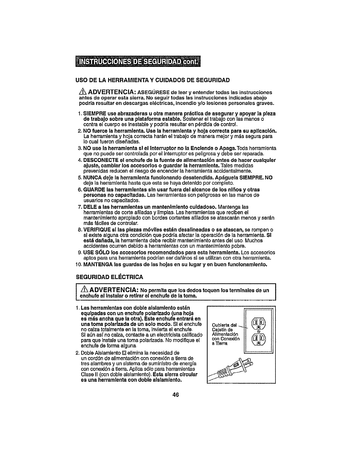
use DELAHERRAMIENTAYCUIDADOSDESEGURIDAD
ADVERTENCIA: ASEGt_tRESE de leer y entender todas las instrucciones
antes de operar esta sierra. No seguir todas las instrucciones indicadas abajo
podrfa resultar en descargas el_ctricas, incendio y/o leslones personales graves°
1. SIEMPRE use abrazaderss u otra manera prdctlcade asegurar y apoyar Is plaza
de trabaJosobre una plataformaestable. Sostensrel trabajoconlas maneso
contra el cusrpo es lnestabley podrfa resultar en p_rdida de control
2oNO fuerce la herramlenta, Use Is herramlenta y hoJacorrecta para su aplleacl6n,
Laherramtenta y hoJacorrects hardn el trsbajo de mansrs major y m_,ssegura pars
Io cua! fusron disefiadas.
3. NO use la herramlenta sl el interrupter no Is Enclende o ApagmToda herramlsnta
qua no puede ser controlads per el Interrupteres pal]gross y dsbessr reparadao
4, DESCONECTE el enchufe de Is fuente de allmentaclSn antes de hater cualquler
ajuste, camblsr los accesorlos o gusrdar la herramlenta.Talesmedidas
prevenidas reducen el rtssgo de encendsr Is hsrrsmtsnts accidentalments.
5. NUNCA deje la herramlenta funclonando desatendlda, Ap_guela SIEMPRE, NO
deje Is herramlanta hasta qua esta ss haya detentdo per completoo
6. GUARDE las herramlentas sin usar fuera del atcancs de los nlSos y otras
personas no capaeltadas. Las herramientas son psligrosas en las manes ds
usuados no capacltadoso
7. DELE alas herramlentas un mantenlmlento cu|dadoso, Mantengalas
hsrramtentasde corteaflladas y IlmplasoLasherramlentssquarecfbenel
mantsnImlentoapropiadoconhordes cortantesaflladosse atascardn manesy ser,_n
m,_sfdclles de controtaro
8. VERIFIQUE sl las plezas m6vltes est_n desallneadas o se atascan, se rompen o
si existsalgunaotra condlcl6nque podrfaafectar Is operacE6nde la herramtenta.Si
est_ da,Sada,la herramfenta debe reclblr mantenlmlento antes del use. Muchos
acctdentes ocurren debido aherramientas con un mantenimiento pobre.
9oUSE S(_LOlos accesorlos recomendados pars esta herramlenta. Losaccesoflos
aptos pare una herram]enta podrfanser dafiinos stse utilizan conotrahsrram_enta.
10oMANTENGA fas guardasde Iss hoJasen su lugar yen buen funclonamlento,
SEGURIDAD ELECTRICA
[z"_ ADVERTENC,A: No permits que ,as dedos toquen lostermlnales de un 1enchufe al Instalaro retlrarel enchufede latoms,
t., Las herramlentas con doble alstamlentoestdn
equlpadas conun enchufe polarlzado (unahoJa
es mds anchaque la otra). Este enchufe entrarden
unatoms polarlzada de un solo mode. S1el enchufa
no catzatotalments en Is toms,_nvlertael snchufs_
SI aL1nasf no calza,contactsaun electrlcista califtcado
pars qua tnstsleunatoma polarizsda_No modtflqueel
enchufade forms alguna,
2. DobleAlslamtento[] eltmlna la necesidadde
un cordSnde sltmentacI6ncon conexl6na tferrade
tresalambres y un slstems de suminlstrode energfa
con conexi6na tlerra.Apltcas61opara hsrmmientas
Class II (con dobleaislamlento).Eats sierra circular
esuna herramlentacon doble alslsmlento.
Cublertadel_ k'_.=_'_]
CaJetfnd_
Altmentaci6n
conConexi6n
aTlerra
46
SEGURIDAD EL_CTRICA cont.
Z_ ADVERTENClA: El doblealslamtentoNO reemplazalas precauclones
de segurldadnormales al operar esta herramlenta.
3. ANTES de enchufarla hermmlenta, ASEGORESE de qua el voItaJede la toma
provistoseencuentre en el tangode voltaicmarcado en la placade fdentificacl6n de
la herramlenta. NO use herramientasconclaslflcact6n"ACsolamente" en una fuente
de allmentacl6nDO,
4. EVITE el contacto corporal con superficies con conexl6n a tierraptalescomo
tuber[as,raadladoras,estufasy refrlgeradores.Exlsteun desgo mayorde descarga
efdctrlca st su cuerpotteneconexl6na tferm
5oNO exponga las herramlentas eldctrlcas a la Iluvla o acondlolones hdmedas nl
use las herramlentas eldctrlcasen ublcaclones hdmedas o moJadas.E!aguaque
Ingresa ala herramtenta eldctrlca lncrementar_el riesgo de descargas el_ctrtcas.
6. INSPECClONE el cord6n de la herramlenta para verlficar la presencla de dabos.
Soliciteal Cantrode ServlcloSears quarepare todocord6ndafiado.ASEGURESE de
estarconstantsmenteatento a ia ubicacl6ndelcord6ny mant_ngalo lejosde la hoJa
en movimiento.
7, NO abuse del cord6n. NUNCE use el cord6n para trasladar la herramlenta nl lo
hale para sacar la toma del enchufe. Reemplacetodocord6ndafiado de fnmed[ato.
Los cordonesdafiados tncrementanel riesgode descargas el_ctrlcaso
CABLES DE EXTENSION
Use un cable de extensl6n aproplado, S6LO use loscablesy cordonesquelndica
UnderwritersLaboratortos (UL).Otros cablesde extensl6npodr{anocasionar unacafda
en la Ifneade voltaje, resultandoen pdrdlda de energfa y sobrecalentam[ento de la
herramlentao
Paraesta herramlenta, se recomiendaun cable de extensl6ncon un tamabo AWG
(AmericanWire Gauge) de por io menos 14 para un cable de extensi6n de 25 pieso
menos de largo. Use uno calibre 12 para un cable de extensi6n de 50 ples. No se
recomlenda el uso de cablesde extensl6n de 100 pies o m_s de largo. Recuerde,
un calibre de alambre mds pequeeiotlene mayor capacldad que uno de mayor
ndmero (unatambrecalibre14 ttensmdscapacldadqua uriccalibre16; unalambre
caltbre12tlenemds capactdad que unocalibre 14)oEn casede dudas, useun n_mero
menoro
AI operar herramientas el_ctdcasen extedores, use un cable de extensi6n para
exteriores marcado "W-A"o "Y¢'.Estos cables est&nclasiflcados para uso en exterlores
y reducen el desgode descargas el_ctrleas.
Z_ PRECAUCI6N: Mantengael cable de extensl6n Ilbre del drea de trabajo.
Positions el corddn de maneratal qua no se atascarden la madera, las
herramlentasu otras obstrucclonesmlentras ustedtrabaJacon una herramlenta
eldctrlca.
Z_ ADVERTENCIA: Revlsetodo cablede extenslSnantes de cada uso. SI
exlsten dabos,reemplace e! cablede Inmedlato.Nunca use la herramlenta con
uncord6n o cable dabado, ya quetocar el drea dabada podrfaocaslonar
descargas eldctrtcas_resultado en leslones graves.
47
S|MBOLOSDESEGURIDADPARASU HERRAMIENTA
La etlqueta en su herramlenta podrfa Inclulr los s[mbolos slgulentes:
V..............................................................................,Voitios
A..............................................................................Amperios
Hz.............................................................................Hertz
W............................................................................... Varies
mln ..........................................................................Minutos
,-'...,.............................................................................CordenteAltema
...........................................................................CordenteContinua
no.............................................................................Veloc]dadsincarga
................................................................................ElaboraclOnClaseII, DobleAislamtento
,../mln......................................................................RevoluclonesoGolpespermlnuto
Z_..............................................................................Indica petlgro,advertencia o precaucl6n.
iSIgniftca atenciSnll!
Su segurldad estd en juego.
SEGURIDAD EN EL SERVICIO
1. SI falta alguna o se tempe, se dobla o falla alguna plaza de esta sierra; osl algdn
componente eldctrlco Ilegara a failer en su desempefio apropiado: APAGUE et
Interrupter de a!lmentactdny retire el enchufede la sierrade la fuentede allmentacfbn
y haga qua la pleza faltante, dafada o fallldasea reemplazada ANTES de resumlr la
operactOn.
2. El servlclo e la herramtenta debe set reallzado s61oen un Centre de Partes y
Reparacl6n Sears, El servicfo o mantenlmientorealizadoperpersonalnocalificado
podrfa resultaren un rtesgode lesf6n,
3, AI prestar servlclo ala herramlenta,use s61oplazas de repuesto Id6ntlcas. Slga
las instrucolones en la seccl6n de mantenlmlento de este manual, El usede
partes no autortzadaso incumpllr conlas instrucctones de mantenimlento podrlacrear
un rlesgo de descargas el_ctrlcas o lestSn.
NORMAS DE SEGURIDAD PARA SIERRAS DE CORTE CIRCULAR DE 3
PULGADAS MULTIUSOiDE CORTE EN PROFUNDIDAD
t_ Mantengalea manes aleJadasdel dreade corte y de la hoJa.
Mantengaambas manes sobre el mangolcublertadel motor.SI ambas manes
, estdn sostenlendo la sierra,la hoJano lea cortard.
I_ Las hoJaadesaceleran deapu_a de apagar la sierra,
PRECAUCI6N:
t, MANTENGA su cuerpo poslclonadoen cualquler lade de la hoJade la sierra y no
en I{neadlrecta con la hoja de la sierra. El rebotepodrfaocaslonar qua la sierra
salte hacia atrds+(Ver"Rebote, o.qu_ Io ocaslona ymanems para prevenlrlo" en las
p_glnas 58, 59 y 60).
2_NO alcance debajo de la pleza de traba]o. La hoja se extlende per debaJode ta
plaza de trabaJoal cortar y podr(a ocastonar leslones.
AI cortar unaplaza de trabajo,la guarda de la hoJaInferior y la
base NO cubren la hoJa,I.ahoJaest_idebaJode la guardsde la hoJaInferiory de
la base (Pdglna65),MantengaSIEMPREsus manes y dedos leJosdel dma de code,
Z_PRECAUCl6N: Estasierra circular NO cuenta con el Slsteme de
GUARDA DE LA HOJA INFERIOR RETRACTABLEestdndar qua se encuentra en
dlsponlble en lee sierras clrculares estdndar. EN ESTAsierra, la guarda de la
hoja Inferior es una parte integral de la base de la sierra (superflcle de corte) y
SOLO enclerra la hoJacuando la mlsma est_iPOR ENCIMA de la base,
48

NORMASDESEGURIDADPARASIERRASDECORTECIRCULARDE3
PULGADASMULTIUSO/DECORTEENPROFUNDIDADcont.
PRECAUCi6N: Cuando la hoJapenetra debaJode la base pare hacerel
torte, la hoJaestd totalmente expuesta por debaJode la plaza de trabaJohaste
bquecorta y pagepor la pleza de trabaJo;en este punto, la guarda de la hoJay la
ase automdtlcamente "CAEP_N" y bloqueardn la hoja POR ENCIMA de la base,
encerrando la hoJaen la guarda de la hoJasuperior e Inferior.
Z_ PRECAUCI6N: FAMILIAR{CESECON ESTE SISTEMA DE GUARDA DE ]
LA HOJA y con la ACCI6N DE PENETRACI6N (descender |a hoJae la I
profundldad deseada)ANTESDE USAR LA SIERRA (Ver Pdglna58, Fig 4 y 4a).
3_VERIFIQUE la Palancade LIberacf6nde ta Guardade la HoJay la Guardade ta HoJa
Inferiory la Base ANTES de cada uso.NO OPERE la sierrast la guarda de la hoja
Inferiory la base nose muevenltbremente y noDESCIENDEN INBTANTANEAMENTE,
ysila palancade liberacl6nde la guardade la hoja nobloquea automdticamentela
guardade la hoJasuperior,DESPUES de que ia hoja reaitceel cortey pase porla
pfezade trabajo(VerPdgfnas58 y 59).
Z_ PRECAUCi6N: Nunca suJeteo amarre la Palanca de Llberacl6n de la
Guarda de la HoJay la Guarda de la HoJaInferior y la Base en posl¢16nelevada
exponlendo la hoJa.Hacerlo no le permttlrfaal ConJuntode Guarda de la HoJa
Inferior y Base de funclonar aproplsdamente despudsde la operacl6n de corte,
Incrementando el rlesgo de leslones personates graves.
4. USE SOLO ta Palancade Uberacf6n de la Guardade la Hoja manuatpare levantarla
base, descender la hoja ala poslci6n de profundldad de corte deseada, al comenzar
la operaci6n de corteo
5. SI la sierra cae por accidente, es postble que la palanca de liberacl6n de ta guarda de
la hoja y ta guarda de ta hoja tnfedor y base podrfan daSarse o romperse. Desclenda y
eleve la hoJamanuatmente(Ver Pdglna 58, Fig 4 y 4a). para aseguratse qua la
palanca de Itberact6n,la guarda y la base todas operen apropiadamente.
6. SI la Paiancade Uberaci6n de la Guarda de la Hoja o la Guardade la Hoja Inferior y la
Base o cuatquierotra plaza de la sierrano operanaproptadamente,DEBE envtarla
sierra aservicio antes del uso..
7. SIEMPRE asegSresede que la Guarda de la HoJaInferfory la Base estdn cubrlendo la
hoJa,y que Ia Palancade Liberacl6n de la Guarda de la Hoja haya bloqueado la hoja
POR ENCIMA de ta base ANTES de colocar la sierrasobra un banco de trabajo o
sobreel suelo.
Dejar la sierra sinque la guarda de la hoJainferior y la base y la palanca de lfberacl6n
de la guardade la hoja sehayan cerrado y bloqueado apropiadamente,poddadejar la
hojaexpuesta debaJode la base, Incrementandoet rfesgo de leslonee personates
graves_Tomenoradel tlempoqua demora la hoJaen detener su rotact6ny la guarda,
base y palanca de llberaci6n para descender y bloquear en laposlci6nde proteccl6n.
8. NUNCA sostenga en sus manos o en sue piernas la pieza a cortar. Es importante
apoyar la plaza de trabaJoapropladamente pare minimizer ia exposicl6n corporal, el
atascado de la hoja o la p_rdida de control.
9. SOSTENGA LA HERRAM1ENTAmedlante las superficies de agarre aisladas
(mango tcuerpo de lasierra) al realizer una operacl6n donde ta herramlenta de corte
podrfa entraren contacto con cables escondidos o con su propto cord6noEl contacto
con cables '_lvos" hard qua las partes metdl]cas expuestasde ta herramlenta le paean
electdctdad al operador.
49
NORMAS DE SEGURIDAD PARA SIERRAS DE CORTE CIRCULAR DE 3
PULGADAS MULTIUSO/DE CORTE EN PROFUNDIDAD cont.
100SIEMPRE suJetela pleza de trabaJode manera segura pars que no se mueva al
reallzar el corte.
11. AI cortar, USAR SIEMPRE una gufa de corte o gufa pars bordes rectos. Esto
mejora la preclst6n del corte y reduce las poslbIIIdades de ateseo de la hoJa.
fix ADVERTENCIA: USE SOLO las hoJasdlsebedas pars ser utlllzedas con ]
ests sierra; tsmefio, forms y orificlo del eJecorrectos. Otras hojss podrfan glrer 1
errdtlcamente y ocaslonar p6rdtda de control, resultandoen leslones graves
(ver pdglne s 56 y 57).
12. NUNCA use arandetss o tuercas de hojas dafiades o Incorrectas.Las arandelas
y tuercas de Iss hoJashartside especlalmente dlsebadas para su sierra, para
un 6pttmo rendlmlento y segurldad de Is operacl6n,
13oUSE S6LO las hoJasdlsefiadas pars cortar et tlpo de materlat pars el cual hart
side recomendadas. Cortar materlales que NO hen side recomendados podrfa
ocaslonar rotura y pdrdlda de control de Is hoJa,resultandoen leslones graves.
14. NUNCA corte mds de una pleza a la vez. NO APILE mrlsde una pleza de trabsjo
sobre el banco de trabajo, a Is vez.
15oEVITE operaclones y poslclones de lss manes Inc6modas deride un resbsl6n
repentlno podrfaocaslonar que su mane se mueva sobre Is hoJa.
16. NUNCA alcance en Is ruts de corte de Is hoJs,
/_ ADVERTENCIA: Clertos pelves producidos at usar herramientas
eldctricas contienen quimicos que el Estade da California ha reconocido
ocastonan cdncer y defectos de nacimiento u etros da_os del sistema
reproductive. Algunos ejemplos de estos qufmicos son:
• Plomo de pinturas a base de plomoo
• Sflice cristalina de ladrillos y cemento y otros productos de mamposter[a.
• Ars_nico y creme, de madera tralada qutmtcamente
Su riesge de esta exposiciones varia, dependiendo de qu_ tan a menudo usted
realiza este ripe de trabajo. Para reduclr su exposiei6n a estes quimieos:
• Trabaje en un _rea bien ventilada.
• Trabaje usando equipo de seguridad aprobado, lal come las mascariltas anti-polvo
que ban side especialmente diseSadas para _trar las partlculas mtcroscOpicas_
Evite el contacto prolongado con polvo proveniente del Iijado, aserrado, triturado,
perforado uotra actividad de construcei6n que utilice herramientas el_ctricas.
Use ropa de protecci6n y lave las dress expuestas con jab6n y agua.
Permitir que el polvo entre en su boca y ojos o descanse sobre su piel podrla promover
]a absorct6n de qulmicos dafinos.
L_ ADVERTENCIA: El use de esta herramienta podria generar y/o disperser
pelves que podrian ocasionar lestones graves y permanentes al aparato
respiratorio, asf come otras lesiones. Use slempre protecci6n respiratoria
aprobada per NIOSH/OSHA en case de exposlci6n al polvo. Didja las particufas
lejos de la cars y el cuerpoo
50

NORMAS ADICIONALES PARA UNA OPERACION SEGURA
ADVERTENCIA: ASEGURESE de leer y entender todas las instruccioneso [
No seguir las Instrucclones listadas a continuact6n podrfa resultar en descargas f
eldctricas, incendios y/o lesiones personates graves.
t, Conozca su herramienta eldctrtca. Lea cuidadosamente el manual det operador.
Aprenda las aplicaciones y las timitaciones, asi come los riesgos potenciales
especificos retacionados con esta herramienta. Seguir esta norma reducir_, el riesgo
de descargas el_ctricas, incendio oiesiones graves
2. SIEMPRE use galas de seguridad oprotectores para los ojos al user esta sierra.
Las galas de vista de diario solo cuentan con lentes resistentes al impacto; NO son
galas de segurldad,
3 PROTEJA sus pulmones. Use una m&scara pare la cara o m_scara anti-polvo si la
operaci6n es polvorienta.
4 PROTEJA sue ofdos. Use protecci6n aprepiada pare los oidos durante et usoo Bajo
ciertas condiciones, el ruido proveniente de este preducto podrfa contdbuir a ta p6rdida
de ta audici6n,
5. TODOS LOS VISITANTES YOBSERVADORES DEIBEN user el mismo equipo de
protecci6n usado per el eperador de la sierra
6. INSPEOClONE los cordones de la herramtenta peri6dicamente y st est_n
dafiados, haga que el Centre de Servicio Sears m&s cercano a usted los repare,
u otra Facilldad de Servlclo Autorizada. ESTE CONCIENTE de la ublcacl6n del
cord6no
7SIEMPRE verifique la herramtenta en case de piezas dafiadas. Antes de user la
herramienta, verifique cuidadosamente toda guarda u otra pieza dafiada para
determiner si la misma funcionar,_ apropiadamente y realizar#, su funci6no Verifique sl
exIste male alineaci6n o atasque de las piezas mSviles, rotura de piezas y cualquier
otra condici6n que podria afeciar la operaci6n de la herramlenta_ Una guarda u otra
pieza que est#, dafiada debe set reparada o reempiazada prontamente en un centre de
Servicio Sears.
8..INSPECCIONE y retire todo clave de la madera antes de aserrar.
9. GUARDE ESTAS INSTRUOCIONESo Refi'_rase aelias frecuentemente y_3selas
para instruir alos demos que podrfan usar esta herramienta. Si alguien toma
prestada la herramlenta, aseg_rese de que tambi_n tengan estas instrucetones.
Husillo
El eje sobre el cual sa ensambla la hoja o herramienta de corte.Tambi_n se le conoce
come ArboL
Revoluctones per Minute (RPM)
El n_mero de vueltas completes de un objeto rotatodo en un minute
Ruta de la hoJa de la sierra
El &rea sobre, debajo, detr&s o frente a fa hoja a medida que corta la pieza de trabajo
Esa &rea que ha side o set& cortada per la hole.
Trtscado
La distancia ala cue! el diente de la hoja de Easierra est,_ doblado (o triscado) hacia fuera
desde la care de la hoja.
Corte per penetracl6n
Una operaci6n de code en el medio o parte interne de una pieza de trabajo, en ta cual la
hoja desciende en ta pieza de trabajo para former una cavldad
Corte de inglete
Una operaci6n de code en la cual la hoja se encuentra en cualquier angulo distinto a
90" de la gufa
51
Corte de ingfete compuesto
Un corte de inglete compuesto es un corte usando un &ngulo de inglete y un _ngulo
biselado al mismo tiempo.
Corte transversal
Una operaci6n de corte oformado qua se realiza transversalmente dal grano de la
pieza de trabajo
Corte biselado
Una operaciSn de corte realizada con la hoja en cualquier _ngulo distinto a 90°de la
mesa de inglete
Carte ranurado
Un corte que no es de penetraci6n, sine qua produce una ranura en la pieza de
trabajo (requiere de una hoja especial).
Corte de chafh_n
Un corte que retira una curia de un bloque de madera de manera ta! que el extreme
(o parte de! extreme) tiene un Angulo distinto a 90°`
Carte longitudinal
Operaci6n de corte a [8 largo de la pieza de trabajo, o cortar a lo largo del grano.
Corte manes libres
Realizar un corte sin usar una gufa, calibre de inglete, accesorio o abrazadera
de trabajo, u otre dispositivo aproptado para prevenir qua la pteza de trabajo gIre o se
mueva durante e! code.
Aserrado profundo
Cuaiquier operaci6n de corte donde la hoja se extiende per complete a tray,s del
espesor de la plaza de trabajo.
Cortes no profundos
Cuatquier operaci6n de corte donde ta hoja no se extiende per complete a trav6s de
la profundidad de la pleza de trabajo, tal come un corte rasurado.
Puntero
El extreme o borde de ta pieza de trabajo en el cual la hoja penetra pdmero
Incisi6n
E! material retimdo per la hoja en un eerie profundo o _aranura pmducida per la hoja
en un corte no profundo o parctal
Rebote
Un riesgo que puede ocurfir cuando la hoja se atasca, lanzando la sierra hacia atr#,s
hacia et operador.
Pieza de trabajo omaterial
El ftem sobre el cuat se realtza la operaciSn de corte, Las superficies de una pieza de
trabajo comt_nmente se denominan caras, extremes o bordes_
Goma
Un residue pegajoso, a base de savia de los productos de madera..
Reslna
Una sustancia pegajosa, a base de savia que se ha endurecido.
52
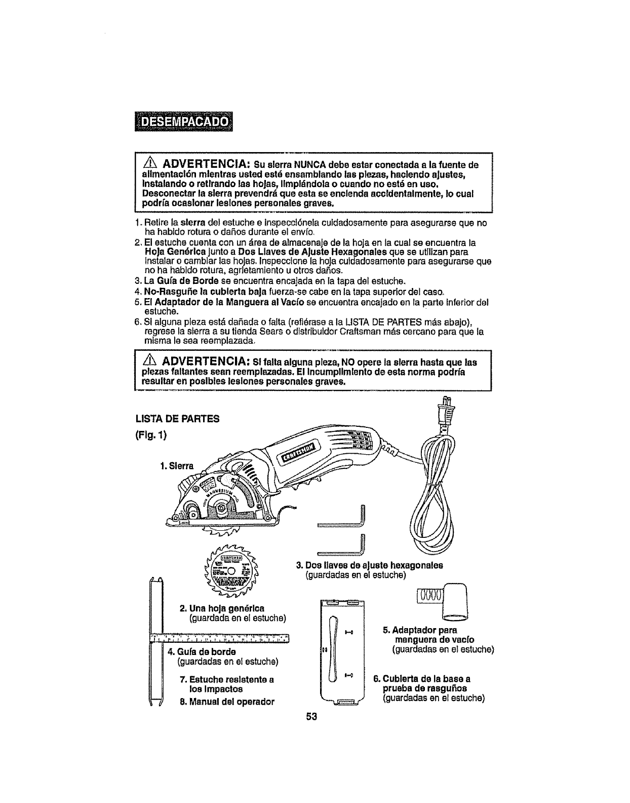
z_ ADVERTENCIA: Su sierra NUNCA debe ester conectada ala fuente de
ellmentscldnmlentras usted estd ensamblandolas plazas,haclendo sJustes,
Instalandoo retlrando las hoJas,Ilmpldndolao cuandono eat6 en ueo.
Desconectarla sierra prevendrdqua eatsse enelendaaccldentalmente,Io cual
podrfsocaslonar leslones peraonalesgraves.
1. Retire la sierra del estucheeinspecci6neiacufdadosamentepareasegurarse que no
ha habidoroturao daSos duranteel env{o°
2. El estuchecuentacon un drea de almacenaJede la hoJaen {acual se encuentrala
HoJaGendrlcs junto a Dos Llaves de AJusteHexagonalee que se utillzan pare
lnstalar o camb]ar las hoJas.Inspeccionela hoJacutdadosamente pare asegurarse qua
no ha habldo rotura, agdetamlento u otrosdaSos.
3. La GuI'sde Borde se encuentra encajadaen la tape det estuche.
4. No-RasguSe ia cublerta baJafuerza-se cabeen la tapasupedor del caso..
5. E! Adaptador de la Manguera a!Vacfo se encuentraencaJadoan la parteinferior de!
es|uche.
6. SI alguna plaza estd daSadao falta (refl6rase ala LISTADE PARTESmds abajo),
regrese la sierraa su tlenda Searso d]strtbutdorCraftsman rods cercano para que la
mtsma Is sea reemplazadao
I _ ADVERTENOIA: s! falta alguna pleza,NO opere la sierra heats que las
plazas faltantes seen reemplazadas.El Ineumpllmlentode esta norma podr[a
resultar en poslbles leslonespersonales graves.
LISTA DE PARTES
(Fig. 1)
1. Sierra
II4. aura de borde
(guardadasen el estuche)
7. Estuchereslstente a
losImpactos
8. Manualdel oparador
3. DosHavesde aJuatehexagonalea
(guardadasenel estuchs)
5. Adaptadorpare
manguerade vac[o
(guardadasan et estuche)
6, Cublerta de Is base a
prueba de rasguPioa
(guardadas en el estuche)
53
CONOZCA SU SIERRA CIRCULAR DE 3 PULGADAS MULTIUSO DE
CORTE EN PROFUNIDAD (Fig, 2)
NOTA: Antes de user su sierra, famlllarfcase con todaa lea funclonss operaclonalea y ]
con los rsquerlmlentos de aagurldad, I
Su sierra circularde corte en profundldad cuenta con un motor sl_,ctrlco de preclsf6n y debe
conactsrse suna fuente de altmentacfdn de 120 voitios 60-Hz AC SOLAMENTE (corriente
normal del hogar), NO opera con cordentacontinua (DC). La gran cards an voltaic ocas[onar_
uns p_rdfdsde fuerzs y el motor se sobrecalentard, Si la sierra no functona cuando est_
enchufada an una toms de t20 volUos,60 Hz AC SOLAMENTE verfflqueIa fuente de
a mantactSm Ests s errs cuenta con un cordSn de allmentscfSn de 8 pies de 2 alarnbrss
(no requiem sdaptsdor),
Esta slerra cuenta con las slgulentes caracterfstlcas:
1. Motor de 2_8Amp, 2800 RMP (velocldsd sin cerga). Ofrece cortesprecisos en readers
contraohapada, compuestos de readers, pldsticos,vtniloy fibre de vfdr]o medisnte el uso
de la hoja de corte gen_rlco pars readers provists, y baldosas de cardmtcs y rn,_rmol
mad]ante el uso de }a hoJa de corte de dtamante qua se vends sepsrsdamente+
2. Laser Tree", ila t3nlca e Innovadora funcl6n pars un corte eficlante y prectso!
3_Luz de trabajo LED Intagrada qua IlumInael ,_rsa de corte para una major vJslbtlidado
4. A|ustes rdpldos de la profundldad de code, con un corte de profundldad mdxims de
7/8 de pulgsdas+
5_Escala de fdcll lectura y f_icll conflguracl6n de Is profundldad de corte t,blcada en
la guards de hoja superior, marcada con fnorementos de 1/8 de pu|gads, 0 a7/8 de
pulgada con Is correspondtenteIongttud(ancho) de corta+
6. Palsnca de Itberacl6n de la guards de la hoJay palancs de levantamlanto a dsdo
del conjunto de la base_ergonSmtcarnente disefiadas pars una operacian aflciente de
la scciSnen profundldsdo
7. Indlcador de Iongltud del code, ublcado en la base. qua muestrs el comlenzo y el final
de la postci6n de la hoja an la plaza de trabajo; ideal pars cortes de cavIdad,
8. Guards de le ho|e de Msgnaslo iiviano de alta reslstencla pars mayor fortalezs y
dursbIIldsd.
9. Base de acero aellada y formads y guards de la hoja Inferior pars dursbtlldad y
large vtda+
10, Cublerta de Is base a pruabs de rssguSos pars user al sorter superficles delicadas
tales como recubrlmlento pars pisos en pl=isttco o compuestoo
1!, Pedal con tnterruptor dlsparador extendldo pars control con ta mano lzquierda ola
derscha, El lnterruptor de liberacl6n de seguridad del dispsrador est_ convenlentemente
ublcado an el pedal pars una f,tctl operact6n,
12. Mango dtsafiado ergon6mlcamante con agarre suave qua saa usta a 3 posiclones
diferentes a 0°, 15" y300 pars corta ads ef ciente, confort y controlrndxirno.
13. Incluye una hoja de acaro pars torte de madera /gendrlca de 3 pulgadas, 20
dlentes con punts al csrburo marca Craftsman', pars cortes r_pidos y susves en
readers contrachapada haste 3/4 de putgada en espesor, compuestos de readers,
pldstlcos,vtnlloy fibre de vldrio.Las hoJssCraftsman de 3 pulgadas de acsro para
corte de dlamante, para cortar baldosas de eardmtca y de mdrmol haste 318 de
pulgadas de espesor, se vends por separado.
14_Dos Ilaves de aJuste haxagonales qua se utlllzan pars Instalsr las hojes.
15. Incluye una Gufa de horde pars ayudar a producircortes rectos preclsos.
16. Puerto integrado pars extracci6n de assrrfn, lnctuya un adaptador pars manguera
1
ai vac[o de 1 ¼pulgsdas pars conexiSn a asplrador h_medoiseco, qua se vends
separadamente, pare retlrar el polvo y las astlUas del _,rea de corteo
17. Rodamientos de bole permanentementa lubrlcados al 100% pars una operscfSnsin
Interrupclonesy large video
18. Engranajss mecanlzadoa de alta reslstencla para una transmistSneflclente de la
energfa,
19, incluye un estuche pars almscenamlento!trasledo reslstente a los Impactoa.
54
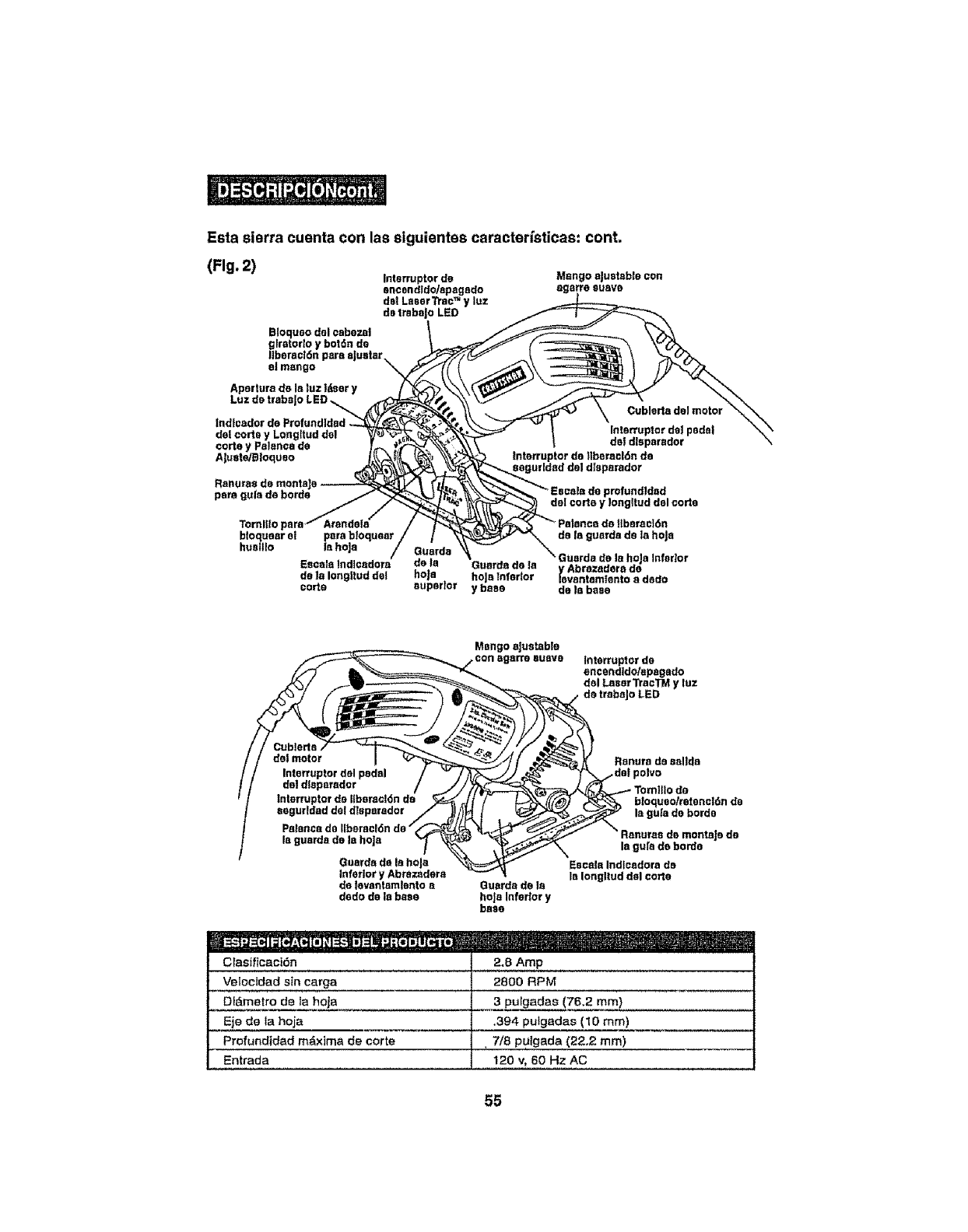
Estasierracuentaconlassiguientescaracterfsticaa:cont.
(Fig.2) Interruptor de
encendldo/apagsdo
de! Laser _sc TM y luz
de trsba]o LED
Bisques dsl aabazal
glrstorto ¥ bar,in de
liberation pare aJustar
el mango
Mango aJuatabla con
Bgsrro suave
Apedura de la luz l_er y
del carte y Longltud dal
carte y Pelancade
Ajuata,'Btoquso
Ranu_a8 de montaJ_
pare guts de bards
tnterruptor do tlbaraclOn de
profundldad
Tornllto
btoquear el pare btoquaar de le guards de le ho|a
hualllo la hoja to la hoJa Infarlor
de Is Guards do ta y Abrazadere de
lavantamlsnto a dado
de ta Ioegltud de!l hoJa hole tnfodor
carte superior ybase dale base
Mango ejustable tntatruptor de
oncandldo/apagado
del Laser TraaTMy luz
dot motor
Interruptor del pedal
dot d!aparador
aaguddad del disparador
Petancedo [IberaclOnde"
la guards do la hoje
Guards de la hole
Inferior y Abrazadera
de Iovantamlanto s
dado de la base
Guards de Is
hoja Infador y
base
Ranurs de solids
btoqueo/ratsnalOnda
la gu_ado bards
ads
le gufa de horde
Escala Indlcedora de
la Iongltud dal €arte
clasi_ic,ac!,_,n..................... 2",B,,A,r_P......................
Velocidad sin carga 2800 RPM
Dldmetro de la hoja 3 pulgadas (76.2 ram)
Eje de la hoja ,394 pulgadas (10 mm)
Profundtdad mdxima de corte , 7/8 puigada (22,2 mm)
Entrada 120 v, 60 Hz AC
55
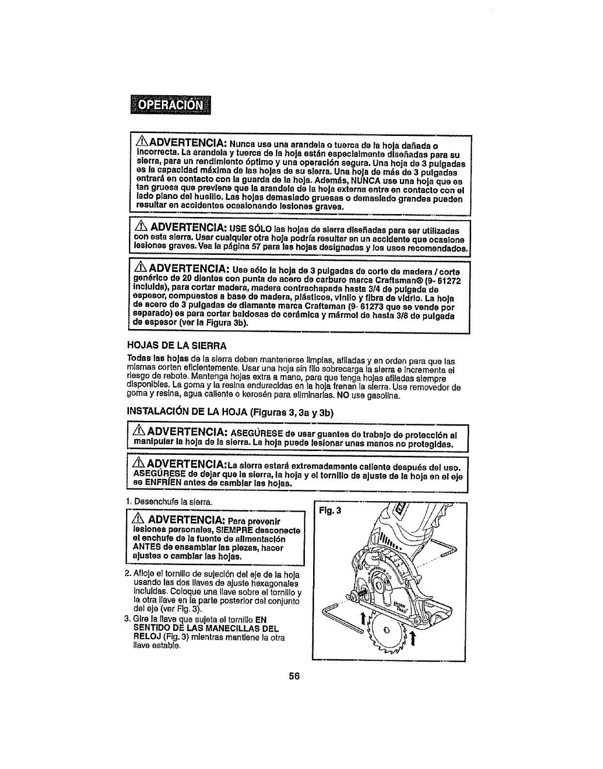
Z_ADVERTENCIA: Nunca use una arandela o tuerca de Is hoja daSada o
Incorrecta. La arandsla y tuama de la ho|a estdn especlalmenta dlseSadas para su
sierra, para un rendtmlento 6primo y una oparact6n segura, Una hoja de 3 pulgadas
es Is capacldad m_ixtma de las hoJas de su sierra. Una heja de mds de 3 pulgsdas
entrard en contacts con la guards de Is hoJaoAdemds, NUNCA use una hoja qua as
tan gruesa qua prevlene qua la arandela de la hoJaexterns entre en contacts con el
tado piano del husillo, Las hojss demastado gruesas o demeslado grandee pueden
insulter en accIdentes ocaslonando leslones graves.
ADVERTENCIA: USE S6LO las hojas de sierra dlssi_adas pars ser utilizadas
son ssta sierra. User cualquler otra hoJa podrfs resultar en un accidents quo ocastone
leslonas graves, Vea la pdglna 57 peru lee hojns dsslgnadas y los usos mcomendados_
.......,i,, J,i
Z_ ADVERTENCIA: Use s61o la hoja de 3 pulgadas de sorts de readers Icorte
gandrlco de 20 dientes con punts de scars de carburo marca Craftsman® (9- 61272
In¢lulds), pars cotter readers, readers contrachapsds haste 3/4 de pu|gads de
aspesor, compuestos a base de readers, pldstlcos, vlnllo y fibre de vldrlo. Ls hoJa
de acem de 3 pulgadas de dlamants mares Craftsman (9- 61273 qua se vends por
separado) es pars cotter bstdosae de cer_imlcs y m_irmot de haste 3/8 de pulgada
de espssor (vet la Figure 3b).
HOJAS DE LA SIERRA
Todas las hoJas de Is sierra daban mantenerse ILmpias,aftladas y en orden pars qua las
m_smas corten sficlentementeoUser uns hoja s_n_e sobracarga _as_erra e tr_crements el
riesgo de reboteo Mantenga hojas extra amsno, pars qua tangs hojas efiladas siempre
disponiblaa. La goma y la resins endursetdaa an la hojs frenan fa sierra, Usa removedor de
goma yresins, agua oatlente o keros_n pars attmlnaflas, NO use gasoline.
INSTALACI6N DE LA HOJA (Ftguras 3, 3a y 3b)
__guantea de"trab'aj0 de pmtec¢i6na--nal'----]
manlpular la hole de In sierra° La hoja puede leslonar unas manse no protegidae.
,, H i ii i i ,,,,,,,,,,,,,,,,,,,,iH
Z_ADVERTENCIA:La sierra estard extremadamsnte salients despu_s dol uso. t
ASEGORESE de deJar qua le sierra, Is hoja y el tornillo de aJuste de la hoja en el eje I
se ENFRIEN antes de,,,,ca,m,b!arlas hojas, .__J
1. Desanchufe ta sierra.
ADVERTENCIA: Psra preven|r
laalones parsonales, S1EMPRE desconacte
el enchufe de la fuente de aUmantacl6n
ANTES de ensamblar lea pie;ms, hacer
aJustes ocambiar lee heJas.
2. Aflole el tornlilode suJecl6n de_eJede Is hoJs
usando las dos Ilaves de ajusts haxagonales
inciuidas,Cotoque une Ilava sobre el tornilioy
la otra llave en/a parts posterior dal conjunto
del aje (ver Fig. 3).
3. Glre la tiave qua sujeta at tornll_oEN
SENTIDO DE LAS MANECILLAS DEL
RELOJ (Fig.3) mlentrss mantIene la otra
]Gaveestable.
Fig. 3
56
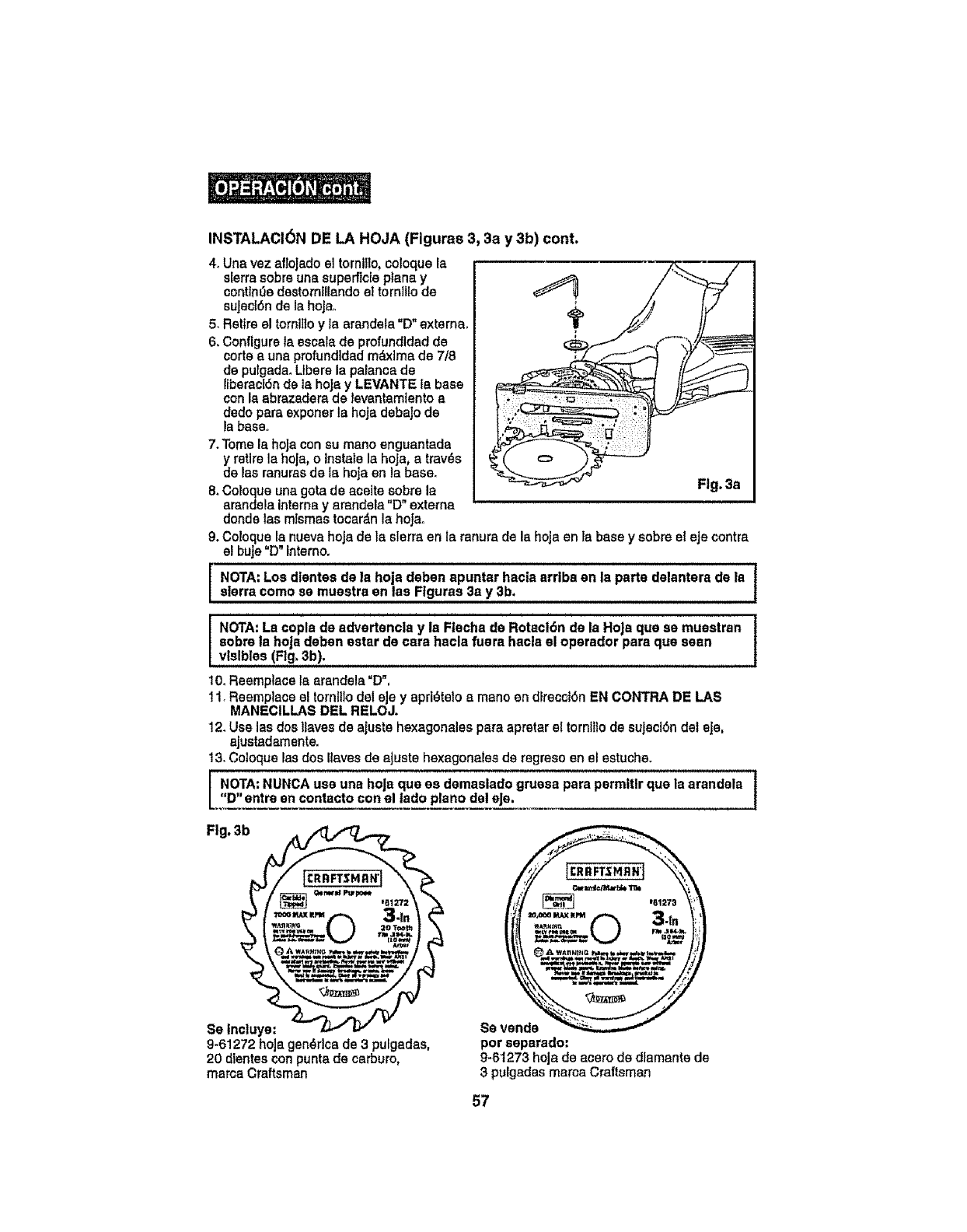
INSTALACI6N DE LA HOJA (Figures 3, 3a y 3b) cont.
4. Una vez afioJado el tornillo, coloque la
sierra sobre una superflcle ptana y
continuedestornillando et tornlllo de
sujecf6n de la hojao
5, Retire el tornlltoy la arandela "D" externa,
6. Configure la escala de profundidad de
corte a una profundidad m_xlma de 7/8
de pulgada. Ltberela palanca de
liberacl6nde la hoJa y LEVANTE la base
con la abrazadera de levantamlenfo a
dedo pare exponer la hoja debajo de
la base,
7. Tome la hoJacon su mano enguantada
y retire la hoja, o Instale la hoJa0a tray,s
de las tenures de la hoja on la base.
8. Coloque una gota de acette sobre la
arandela interne yarandela "D" extema
donde las mismas tocar_n la hoJao
,w
Fig. 3a
9. Coloque la nueva hoja de ta sierra en la ranura de la hoja en la base y sobre el eje contra
el buJe"D" intemo.
NOTA: Los dlentes de la hoja deben apuntar hacia arrlba en la parts delantera de la t
slerra como se muestra en lea Figures 3a y 3b. I
7
NOTA: La copla de advertencla y la Flecha de Rotacl6n de la Hoja qua se muestran |
cobra la hoja deben ester de care hacla fuera haeta el operador pare qua seen i
vfslbles (Fig, 3b).
10. Reemplace la arandela "D",
11. Reemplace el tornlUodel eJey aprl_felo a mano en dlrecetSn EN CONTRA DE LAS
MANECILLAS DEL RELOJ.
12. Use las dos llaves de ajuste hexagonales pare apretar el tornltlode sujeci6n del eJe,
ajustadamente.
13. Cotoque las dos Ilaves de aJuste hexagonales de regreso en el estuche.
NOTA: NUNCA use una hoJaqua es demaslado gruesa para permttlr qua la arandala I
"D"entre en contacto con el |ado piano del eJe, I
Fig, 3b
Se tncluye:
9-61272 hoJagen_dca de 3 puigadas,
20 dientescon punta de carburo,
mama Craftsman
8e VeRde
per seperado:
9-6t273 hoja de acero de dlamante de
3 pulgadas marca Craftsman
57
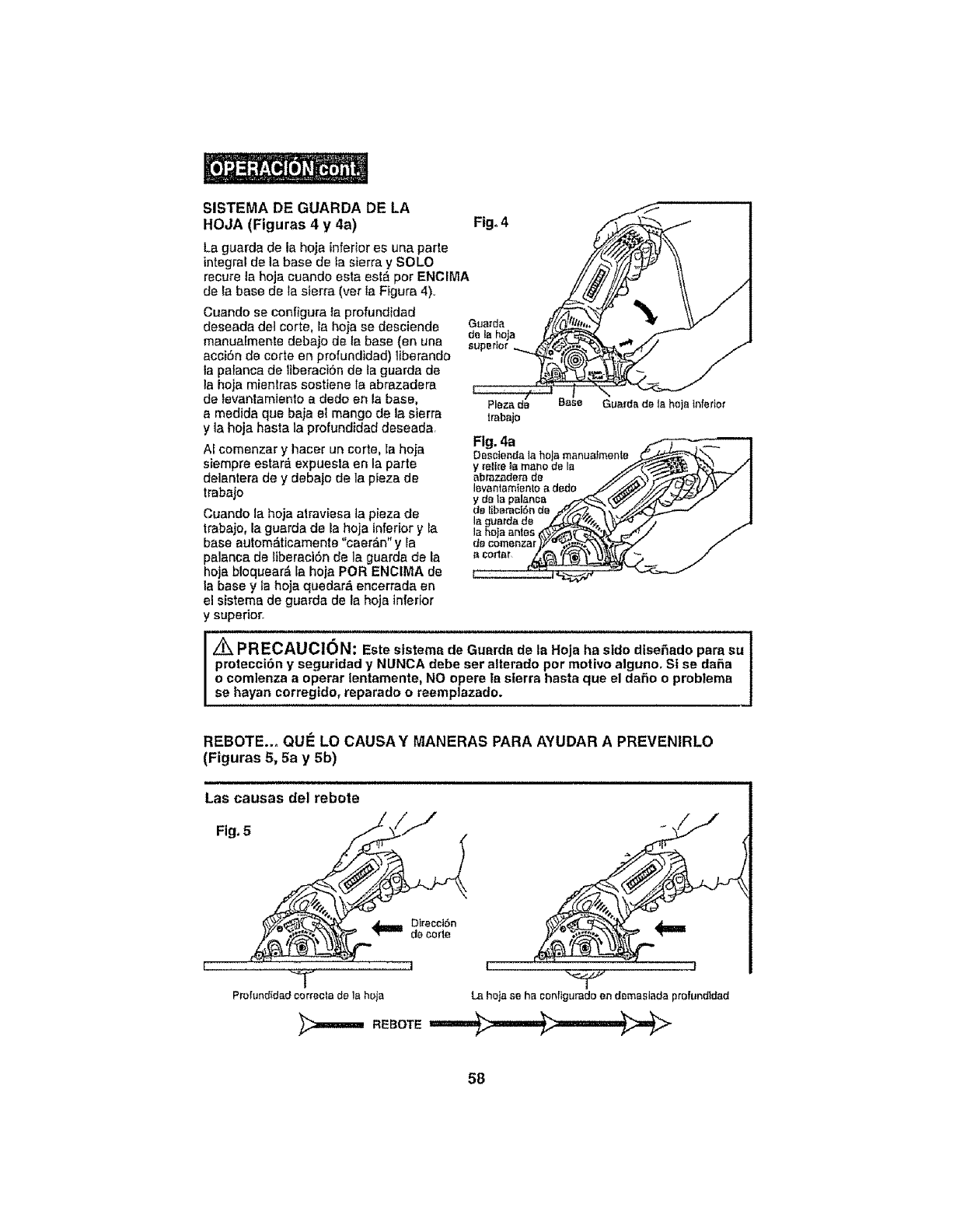
SISTEMA DE GUARDA DE LA
HOJA (Figuras 4 y 4a)
La guarda do la hoja inferiores una parte
integral do la base do la sierra y SOLO
recure la hoja cuande esta est_ per ENCIMA
de la base de la sierra (vet la Figure 4)..
Cuando se configure la profundidad
deseada del carte, ia hoja se desciende
manualmente debaje do ta base (an una
acci6n de carte en profundidad) iiberando
la palanca de liberact6n de la guarda de
la hoja mienlras sosttene la abrazadera
de levantamiente a dedo on la base,
a medida qua beja el mange de la sierra
yla heja hasta la profundidad deseada
Af comenzar y hacer un carte, ia hoja
siempre estard expuesla en la parte
deiantera de y debajo de la pieza de
trabajo
Cuande la hoja atraviesa la pieza de
trabajo, la guarda de la hoja inferior y Fa
base automdticamente "caerdn" y fa
palanca de liberaci6n de la guarda de la
hoja bloquear,_ ia heja PeR ENCIMA de
la base y la heja quedara encerrada en
el sistema de guarda de la heja inferior
y superior.
Fig. 4
Plaza da Guarda de la hoja tnfedm'
trabajo
Fig. 4a
Oescienda la he a manualmente _-,(_.._.
levantamientoa dedo ._//_'Yy///i_;L_-_ y
ydata palanca _ ('_/./'//"_/
la guatda de _"_. _'_'_ .// ./
I_PRECAUC1ON: Este ststema de Guarda do ta Heja ha side diseSado para su
protecci6n y seguridad y NUNCA debeser allerado par matlvo alguno. St se dafa
o comlenza aoperar tentamente, NO opere la sierra hasta que el daSo o problema
se hayan corregido, reparado o reemplazade.
REBOTE..o QUE LO CAUSAY MANERAS PARA AYUDAR A PREVENIRLO
(Figuras 5, 5a y 5b)
=IH, i, ==, = == == = i=
Las causas del rebate
Fig, 5 __
_ Direccl6n
do code
fI
"7
Proiund_dad correcta de la hoja La hoja se ha configurado en d_masiada profundldad
58
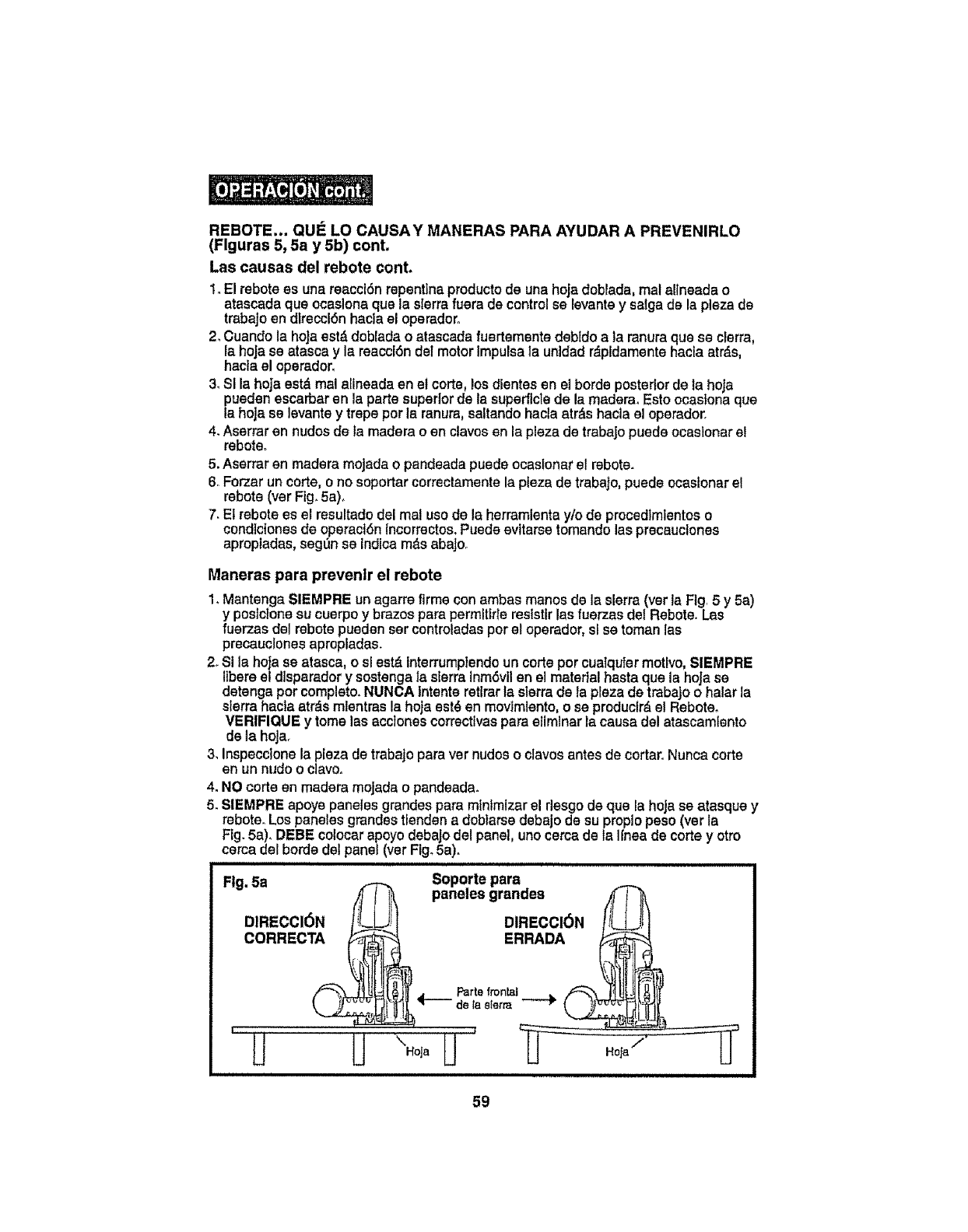
REBOTE...QUI_LOCAUSAYMANERASPARAAYUDARA PREVENIRLO
(Flguras5,5ay 5b)cont.
Lascausasdel robotscont.
1° El rebotees una reacci6n repentfna producto de una hoja doblada, real altneada o
atascada qua ocaslona qua la sierrafuera de control se levantey salga de la plaza de
trabaJoen dlreccl6n hacla el operador.
2oCuandola heJaest&doblada o atascada fuertemsnte debido a la ranuraqua se cIerra,
la hoJase atascay la reaccl6n del motor Impulsa ta unldad r_ptdamente hacia atr_,s,
hacla el opsrador,
3. SI la hoja estd mal alineadaen el corte, losdlentes en el borde posterior de la hoJa
_auedenescarbar en la parts superior de ta superflcle de la madera. Esto ocastona qua
hoja se levante y trope perla ranura, saltando hacla atr&shacla el operador.
4. Aserrar en nudes de la madera o en clavos an la pleza de trabajo puede ocaslonar e!
reboteo
5. Aserrar en madera mojada o pandeada pusds ocaslonar et robots.
6_Forzar un corte, o no soportar correctamente la plaza de trabaJo,pueda ocaslenar el
rebote (ver Fig. 5a).
7. El rsbotaes el resultado del mal use de la herramlenta y/o de procedlmlentos o
cond]ctones de operact6n Incorrectos.Puede evttarse tomando las precauclones
aproptadas, segen se indicam_s abajoo
Maneras pars prevenlr el robots
1. Mantenga SIEMPRE unagarre firms conambas manes de la sierra(ver la Fig 5y5a)
y postc{onssu cuerpo y brazes parapermftlds reststtr las fuerzas del Rsbote. Las
fuerzas de1robots pusden ser controladas per el operador, sl se toman las
precauctones apropladas.
2. Si la hoja ss atasca, o sJest& interrumptendoun corte per cualqu{er motive,SIEMPRE
Ilbere el dtsparadory sostenga la slerraInm6vilen el material hasta qua la hoJase
detenga per complete.NUNCA Intentsretirarla slerra de la plaza de trabajo o halar la
sierra hacta atr_smlentras la hoja est_ en movlmlento, o se produclrdel Rsboteo
VERIFIQUE y tome las acctonescorrectivas para elimlnar la causa del atascamtento
de la hoja.
3_inspecclons la pleza de trabajo para ver nudes o clavos antes de cortar. Nunca corte
en un nude o clave°
4. NO corte en madera mojada o pandeada.
5. SIEMPRE apoye pansies grandes para minlmlzar el riesgo de qua la hoja se atasque y
rebote. Los pansiesgrandss tiendsn a dobtarse debajo de su proplo peso (ver la
Ftg. 5a). DEBE colocar apoyo debajo del panel, uno cerca de la IInea de corte y otro
cerca delhorde del panet(ver Flgo5a).
::::::::::::::::::::::::::::::::::: ul u l
Fig. 5a _Soporte pars
4(I_ pansies grandes _'f'_
DI.ECCIO. DIRECCl0.
co..EcTA E. OA
u==ul i
59
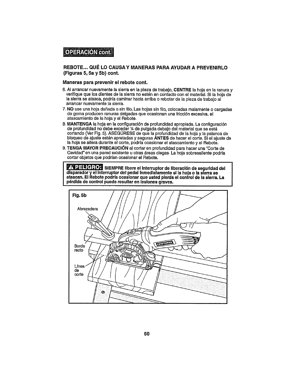
REBOTE... QUE LO CAUSAY MANERAS PARA AYUDAR A PREVENIRLO
(Figuras 5, 5a y 5b) cont.
Maneras para preventr el rebote cont.
6. AI arrancar nuevamente la sferra en la plaza de trabaJo,CENTRE ia hoja en la ranuray
vedflque qua los dientes de la sierra no est_n en contacto con el material. Si ta hoja de
la slerra se atasca, podr[a caminar hacia arrfba o rebotarde la pleza de trabajo al
arrancar nuevamente la slerra.
7. NO use una hoja daSadao sin fllo. Las hoJassin ffio, colocadas malamente o cargadas
de goma producen ranuras delgadas qua ocastonan una friccESnexcesiva, et
atascamiento de la hoja y el Rebote.
8oMANTENGA la hoJaen la configuraciSn de profundidad aproplada. La configuract6n
de profundfdadno debe exceder ¼ de putgada debajo del matertal qua se estd
cortando (Ver FIgo5).ASEGORESE de qua la profundldad de la hoja y ta palanca de
btoqueo de ajuste est_n apretadas y seguras ANTES de hacer el corte. Si el ajuste d8
la hoJase altara durante el corte, podr{a ocaslonar e! atascamlento y el Reboteo
9,_TENGA MAYORPRECAUCI6N al cortar en profundtdad para hacer una"Corte de
Cavldad" en una pared exlstente u otras &reasclegas. La hoja sobresallente podr{a
cortar objetos qua podrfan ocaslonar el Rebote.
StEMPREllbere el interruptor de tlberacldn de segurldaddel
dlsperadory el Interruptordel pedal Inmedlatamente sl la hoJao la sierra se
atascan,El Rebote podrfaocasloner que usted plerdsel control de la slerra.La
pdrdldade control puede resultaren lestonesgraves,
,,u,,ll, ............................
Fig. 5b
6O
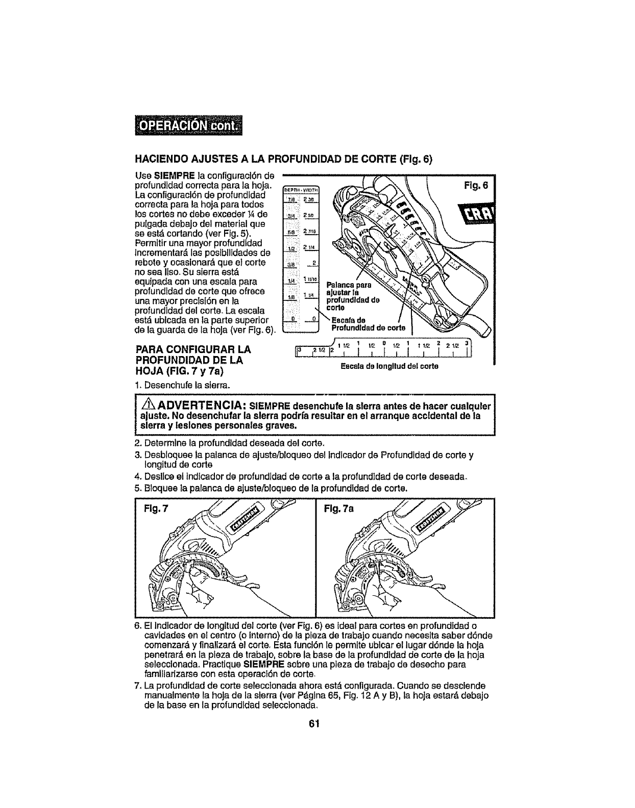
HACIENDO AJUSTES A LA PROFUNDIDAD DE CORTE (Fig. 6)
Use SIEMPRE la conflguracl6n de
profundtdad correcta para la hoJa.
La configuract6n de profundldad
correcta pars la hoja para redes
loscortes no debeexcsder ¼ de
pulgada debajo del material qua
se estd cortando (ver Fig.5).
Permitfr una mayor profundldad
lncrementar_,las pos]bllldadesde
rebotey ocasionar_ qua el corte
no sea Ilso°Su sierra estd
equipadacon unaescala pars
profundidad de corte qua ofrece
una mayor preclsl6n en _a
profundEdaddel corte. La escala
estd ublcada en la parts superior
de la guards do la hoJa(ver Fig.6).
PARA CONFIGURAR LA
PROFUNDIDAD DE LA
HOJA (FIG. 7 y 7a)
1. Desenchufela sierra.
z_ADVERTENCIA: i
SIEMPRE desenchufe la sierra antes de hacer cualquler !
ajuste. No desenchufar la sierra podrfaresuttar en el arranque accidental de la !
sierra y leslones personales graves, |
2, Determinela profundidad deseada del corte,
3. Desbloquee la palanca de ajuste/bloqueo de! lndlcador de Profundldad de corte y
Iongitud de corte
4. Desltceel tndlcadorde profundidad de cortea la profundIdad de corte deseadao
5. Bloquee la palanca de aJuste/bioqueode la profundldadde corte.
6. El Indfcadorde Iongltuddel corte (ver Fig. 6) es idealpara cortes en profundfdad o
cavidades en el centre (o Interne)de la pieza de trabaJocuando neceslta saberd6nde
cemenzard y flnalizardel corte. Esta functSnle permits ubtcar el lugar d6nde la hoja
penetmrden la plaza de trabaJo,sobre la base de ta profundldad de corte de la hoja
selecclonada. Practique SIEMPRE sobre una plaza de trabajo de desecho para
faml_larlzarsecon esta operacidn de corte.
7, La profundidad de corte selecclonada ahoraestd configurada. Cuando se desclsnde
manualmenta ta hoJade la sierra (ver Pdglna65, Fig. t2 A y B), la hoJaestard debajo
de la base en la profundldad selecclonada.
61
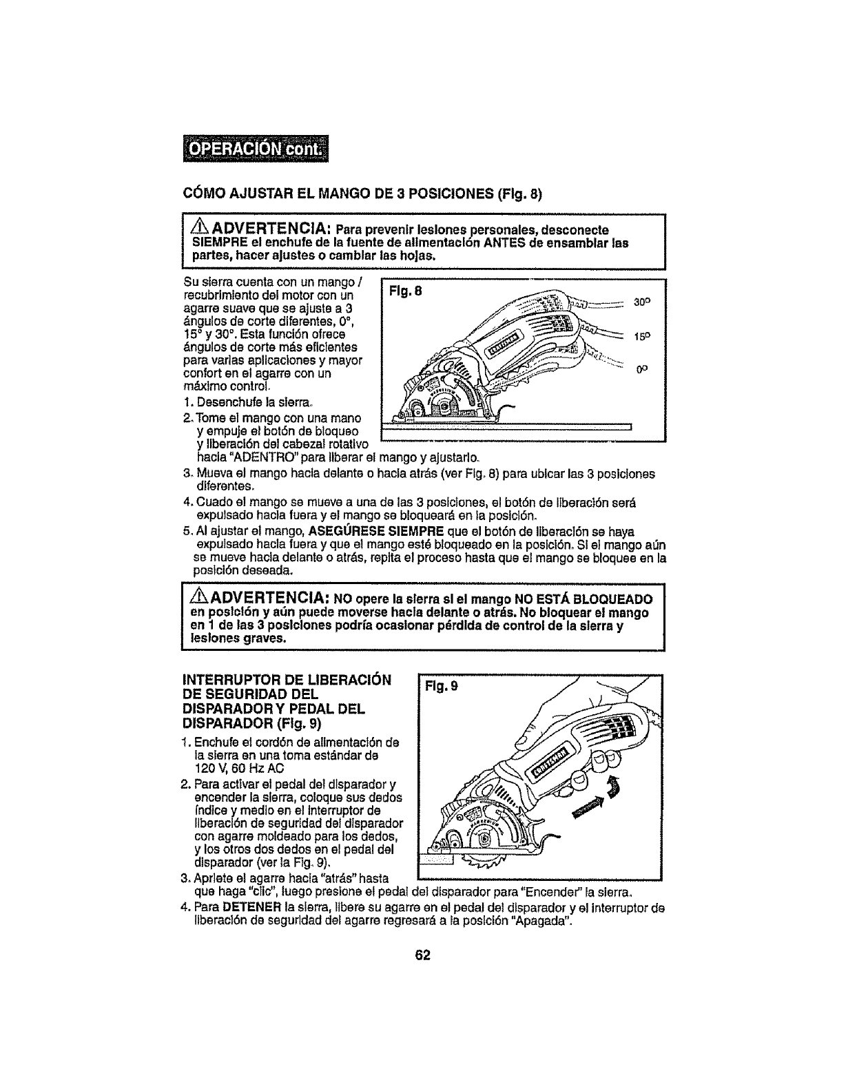
C6MO AJUSTAR EL MANGO DE 3 POSlCIONES (Fig. 8)
Z_ ADVERTENCIA: Para prevenlr leelones personales,desconecte
SIEMPRE el enchufe de la fuente de allmentaclon ANTES de ensamblar lae
partes, hacer aJusteso camblar las hoJas.
Su sierracuentacon un mango /
recubrimientodal motor con un
agarre suavequase ajusts a 3
dngulos de corte diferentes, 0°,
15° y 30°. Esta funciSn ofrece
&ngulos de corte m&seflctentes
paravsdas aplicaclones y mayor
conforten el agarra conun
m_r=xlmocontrol
t. Desenchufela sierra°
2.Tomeel mangocon unamane
yempuje el bot6nde bloqueo
y Itberaci6ndet cabezalrotatfvo
Fig. 8 30°
15o
0o
hacla "ADENTRO" para llberar el mango y ajustsrlo.
3oMueva st mango hacla delante o hacla atrds (ver Fig. 8) para ublcar las 3 poslclones
dlferentes.
4. Cuadoel mango se muevea una de las 3 poslclones, e! betdn de Itberact6nserd
exputsado hacla fuera y el mango se bloqueard en ta posict6no
5. AI ajustarel mango,ASEGORESE SIEMPRE qua el bot6n de Ilberac]6nse hays
exputsado hacla fueray qua el mango est_ bloqueado en la posicl6n. SI el mango a_n
se mueve hacla delante o atrds, replta el proceso hasta qua el mango se bloquee en la
poslci6n deseada.
I _ADVERTENCIA: NO opere Is sierra sl el mango NO EST._ BLOQUEADO
en poslcldn y son puede moverse hacls delsnte o atrds. No bloquear el mango
en 1 de las 3 poslclones podria ocsslonar pdrdldade control de la sierra y
leslones graves.
INTERRUPTER DE LIBERACI6N
DE SEGURIDAD DEL
DISPARADOR Y PEDAL DEL
DISPARADOR (Fig. 9)
I. Enchufeet cordSnde altmentact6nde
ia sierra en una tomaest&ndardo
120 V,60 Hz AO
2. Psra acttvar el pedal del dlsparador y
encender la sterrs, coloque sus dedos
fndlce y med]o en el Interrupterde
Itbersci6nde segurldad deldlsparador
con agarre moldeado para los dsdos,
y los otros dos dodos en el pedal del
d]spsrador (ver Is Flg.9),
3, Apr]eta et agarre hacla "atr,_s"hasta
Fig. 9
qua haga "clic", luego presione el pedal del disparador para"Encender" la sierra.
4. ParaDETENER la sierra, Ilberesu agarre en el pedal det dtsparadory el interrupterde
llberacl6n de seguddad del agarre regresar&sla poslclSn"Apagada".
62
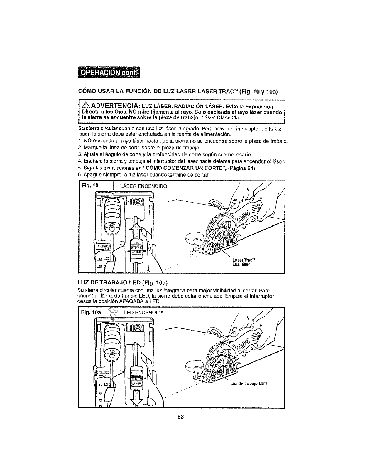
come USAR LA FUNCION DE LUZ LASER LASER TRAC" (Fig. 10 y 10a)
ADVERTENClA: LUZ LASER. RADIACI(_N LASER. Evtte la Exposici6n
DIrecta alos Ojos. NO mire fijamente al rayo. $61o enclenda el rayo tfiser cuando
la sierra se encuentre sobre la pteza de trabajo. Lfiser Clase Ilia°
Su sierra circular cuenta con una luz t&ser integrada,. Para activar el interrupter de la luz
_ser, la sierra debe estar enchufada en la fuente de afirnen'tact6n.
1 NO encienda el rayo ffiser hasta que la sierra no se encuentre sobre la pieza de Irabajo.
2, Marque ta finea de corle sobre la pieza de trabaje,
3Ajuste el __ngulode corte y la profundidad de corte segL_nsea necesario,
4, Enchufe la sierra y empuje el interrupter del t_ser hacta delante para encender el t&sec
5 Siga ]as instrucciones en "COMO COMENZAR UN tORTE", (P&gina 64).
6,_Apague siempre la luz laser cuando termine de cortar.
IFig, 10 ! LASER ENCENDIDO
LUZ DETRABAJO LED (Fig, 10a)
Su sierra circular cuenta con una Iuz Integrada para meier visibilidad al cortar Para
encender la luz de |rabajo LED, la sierra debe estar enchufada Empuje el interrupter
desde la posici6n APAGADA a LED,
Fig. 10a LED ENCEND1DA
63
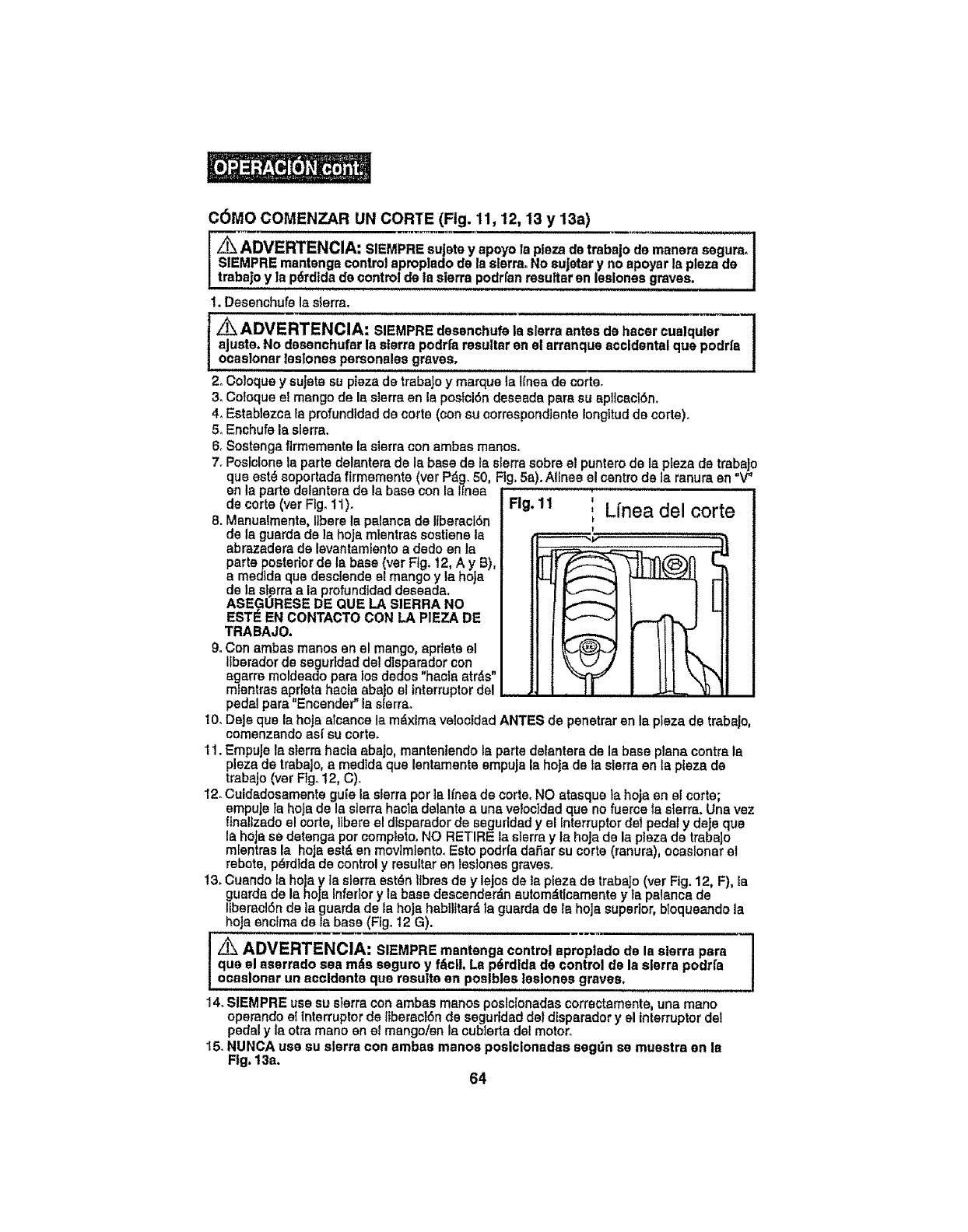
C6MO COMENZAR UN CARTE (Fig. 11, 12, 13 y 13a)
Z_ ADVERTENClA: SIEMPRE sujeta y apoyo la pieza de trabajo de manera segura_ J
SIEMPRE mantenga control aproplado de la sierra. No sujeter yno apoyar la plaza de |
trabajo y la p_rdida de control de ta sierra podrfan resuttsr an leslonas groves. J
I. Desenchufe la s_erra.
I Z_ ADVERTENCIA: SIEMPRE dasenchufe ,a sierra antes de hacar cualqular 1
aJuste. No dasanchufer la sEerra podrfa resultar sn el arranque accidental qua podrfa
ocaslonar laslonaa personeles graves.
2. Cotoque y suJatasu plaza de trabaJoy marque la lfnea de carte.
3, Coloque el mango de Is sierra en Is poslci6n deseada pars su apitcsct6n.
4, Establezca ta profundtdadde carte (con su corraspondiente Iongltudde carte),
5. Enchufe Is sierra.
6. Sostanga flrmamente la sierra con ambss manes.
7. Postcfone Is parle delsntera de Is base de Is sierra sabre el puntero de Is pEezade trabs]o
qua est_ soportads firmemente (vet P_g. 50, Fig. 5a). Alines el centre de ]a ranura en "V"
en la parts delantera de la base con la Ifnea
decorte(verFlgo11), FIg.11 " Lfnea del carte
8. Manualmente0 libere Is palanca de IIbersciSn
de Is guards de la hoJa mlentras sostiene Is _,
abrazsdera de levantamlento a dedo en Is
parts posterior de Is base (vet Ftg. 12, A y B),
a medtda qua dasclende el mango y la hoja
de Is sierra s Is profundidad deseada.
ASEGORESE DE QUE LA SIERRA NO
EST'- EN CONTACTO CON LA PIEZA DE
TRABAJO.
9. Con ambas manes an el mango, aprlate el
liborsdor de seguddad del disparador con
egsrrs moldeado psra los dedos "hacta str_s"
mlentras aprieta heels sbaJo el interrupterdel
pedal pare "Encender" Is sierra.
10. Deje qua la hojs alcance la mdxima veloeidad ANTES de penetrar en la plaza de trabsjo,
comenzando as( su carts.
11, EmpuJeIs sterm hacts sbajo, mantenlendo is parts delanters de la base plans centre !s
plaza de trabajo, a medtda qua lentamente empuja la hoJade la sierra en ta plaza de
trabajo (ver Ffgo12, C).
12. Cuidsdosamsnte gufe Is sierra per is lfnea de carte, NO atasque la hoja en el carte;
empuJe is hojs de Is sierra hacla delsnte a uns velocidad qua no fuerca fs s_erra.Una vez
finaltzsdoel carte, libere el dtsparsdor de seguridad y el Interrupter del pedal y deje qua
Is hoJsse detenga per complete. NO RETIRE la sierra y la hoja de Is plaza de trabsJo
mlentras la hoja eat& en movimtento. Esto podr(a dai=iarsu carte (ranura), ocsslonar el
rebate, p_rdida de control y resultar en teslones graves.
13. Cuando is hoja y ls sierra est,_n tlbres de y lajos de Is plezs de trabaJo (ver Fig. 12, F), la
guards de la hoJa Inferior y Is base descender_n autom_ticamente y !s paisncs de
liberscl6n de la guards de la hojs habilttar_, Is guarda de la hoJa superior, bloqueando Is
hoja enctma de ta base (Fig. I2 G).
Z_ ADVERTENCIA: SIEMPRE mantenga control eprop|ado de la sierra pars 1
qua el asarrado sea rods seguro y fdcll. Le p6rdida de control de Is sierra podrfa Iocaslonar un accidents qua results en poalbles lsslonee graves.
14. SIEMPRE use su sterra con ambss manes poslclonadas correctamente, una mane
operando el Interrupter de llberscl6n de seguridad det dispsrador y el interrupter del
pedal y Is otra mane en el mango!an fs cubterta dal motor°
15, NUNCA use su sierra con ambas manos posiclonadas sagdn se muestra sn la
Fig, t3a.
64
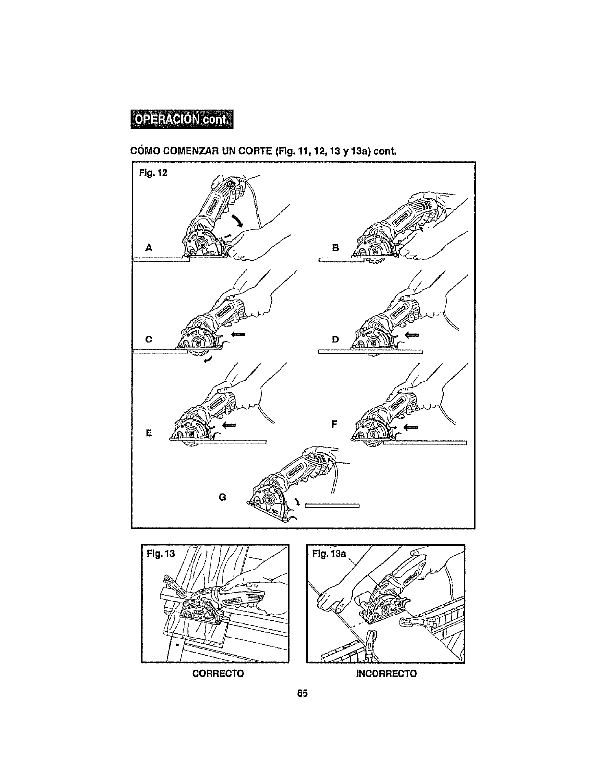
C6MO COMENZAR UN CORTE (Fig. 11, 12, 13 y 13a) cont.
Fig. 12
A
C
E
Fig. 13
CORRECTO INCORRECTO
65
Para ayudarle a mantener el control:
1_SIEMPRE seporte ta pEezade trabajo cerca el corte_
2. SIEMPRE seporte la pIeza de trabaJopara que el corte quede de su derecha,
3. SIEMPRE sujete la pleza de trabaJopara que no se muevadurante el corte. Coloque
ta ptezade trabaJocon el ladebueno hacta abaJoo
NOTA:El lade bueno de la plaza de trabajo es el lade donde la aparlenclaes
lmportante.
4. NUNCA coloquela sierra en la parte de la pfezade trabaJoqua sa caarda! hacer el
corte (vet Fig.13a)°
5. SIEMPRE mantanga el cord6nleJosdel drea de corte.SIEMPRE coloqueel cord6nde
maneratal quano cuelguesobre la plaza de trabajoal haceretcorte,
,,,,,,,,,,,,,,,,,,,,, ,,,,, ,,, ,, ,, , ,
Z_ ADVERTENCIA: Sl el cord6n cuelga sobrela plazade trabsJoduranteel
corte, Ilbereel Interrupterdeldlspsrador.Paraevltarleslones,desenchufela sierra
y muevael cord6npars prevenlrque cuelguede nuevo.
J_ Usar una sierra con el corddn daitado podrfa resultar en [
I
Idslonea graves o muertes. SI el corddn se ha dafiado, reempldcelo antes de i
usar nuevamente ia sierra.
6oA! hacerun code, SIEMPRE apllquepresi6nIgualy constante.Forzarla sierra
producecortesdestgualesy podrfaacortarla vlda_til de la sierra u ocasionarel
Rebote.
Z_ PRECAUCI6N: Esta sierra circular NO cuenta con una guarda de ta
hoJaInferior retractable qua se encuentra en sierras clrculares est_-ndar.EN
ESTA sierra, la guarda de la hoJaInferior es uns parte Integral de Is base de
la sierra y s61oenclerra Is hoja PeR ENCIMA de Is base de la sierra. Cuando
se conflgura la profundldad de torte deseada, la hoJabaJamanualmente
(accldn de profundldsd) debajo del con Juntode la guards Inferior de aloJay
Is base pars hacer el corte. Esto se hate Itberando la palanca de Ilberacl6n
de Is guards de la hoJa.
Una vez reallzado el corte y una vez la hoJaatravlese la plaza de trabaJo,el
conJuntode la guards de la hoJaInferior y la base automdtlcsmente "caerdn"y
la palsnca de Ifberacl6n de Is guards de la hoJabloqueard la guards de la hoJa
superior en poslcl6n y la hoja quedard PeR ENCIMA de ta base encerrada
entre los conjuntos de la guards de la hoJaInferior y superlor y la base,
Z_ PRECAUCI6N: Famlllarfceseconeste SISTEMA DE GUARDADE LA
HOJAy con la ACCi(_NEN PROFUNDIDAD(baJandota hoJas la profundldad
desesda) ANTES DE USAR esta sierra.
,,,,,,,,,,,,,,,,,,,,, , , I
66
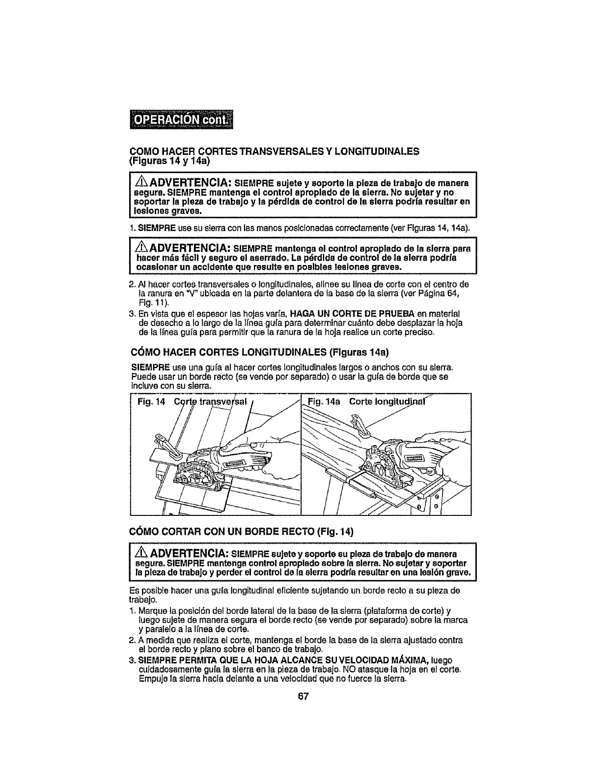
COMOHACERCORTESTRANSVERSALESYLONGITUDINALES
(Flguras14y 14a)
z_ADVERTENCIA: SIEMPRE sujete y soporte la plezs de trabajo de msnera
segura. SIEMPRE mantengs el control aproplado de la sierra. No sujetar y no
soportar la plaza de trabajo y la pdrdlda de control de la sierra podr|a resuttar en
leslones graves.
1, SIEMPRE use su sierra con las manos posictonadas correctarnente (ver Figuras 14, 14a)_
I _ADVERTENCIA: SIEMPRE msntenga e! control aproplado de la sierra pars
hacer rods fdcll y seguro el aserrsdo. La pdrdlda de control de la sierra podrfa
ocasionar un accidents qua results en poelbles leslones graves.
2_AI hacer cortes transversales o longttudinales, atlnee su Ifnea de corte con el centro de
la ranura en =V" ubtcsda en la parts delantera de la base de Is sierra (ver P_glna 64,
Ftg, 11).
3. En vista que el espesor las hojas varfa, HAGA UN CORTE DE PRUEBA en material
de desecho a Is largo de Is Ifnea gufa para determiner cu_nto debe desplazar la hoJa
de la lfnea gufa psra perm[ttr qua la ranura de Is hoJa realtce un corte preciso°
C6MO HACER CORTES LONGITUDINALES (Flguras 14a)
SIEMPRE use una gufa al hacer cortes longitudinales largoso anchoscon su sierra,
Puede usarun borde recto (ss vendspor separsdo) o usar la guta deborde qua se
Incluvecon su sierra.
Fig, 14 ,14a
COMO CORTAR CON UN BORDE RECTO (Fig. 14)
Iz/ik' ADVERTENCIA: SIEMPRE sujete y s°p°rte su plaza de trabaj° ds msnsra !
segura. SIEMPRE mantsnga control aproplado sobre la sierra. No sujetar y soportar
la plaza de trabaJo y perder el control de Is sierra podrfa resultar en una lesl6n grave.
Es posibfe hacer uns gufa longitudinaleflctente sujetando un horde recto a su pteza de
trabajs,.
1oMarque Is poslclSn del borde lateral de la base de la sierra (ptataforma de corte) y
lusgo suJete de manera segura el borde recto (se vende por separado) sobre la marca
y pamlelo a la IInea de corteo
2oA medida qua realiza el corte, mantengs el borde Is base de la sierra ajustado contra
el horde recto y piano sobre el banco de trabajo.
3. SIEMPRE PERMITA QUE LA HOJA ALCANCE SU VELOCIDAD MAXIMA, luego
cutdadosamente gufa {a sierra en la plaza de trabajo_NO atasque la hoja en el corte_
EmpuJe Is sierra hacia delante a una vetocldad qua no fuerce !s slerra_
67
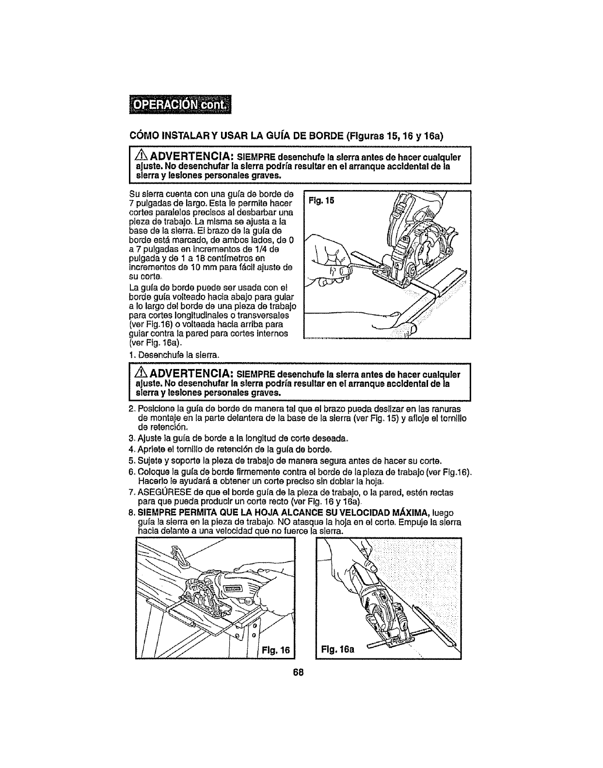
C6MO INSTALAR Y USAR LA GUfA DE BORDE (Flguras 15, 16 y 16a)
,'_ ADVERTENClA: SIEMPRE desenchufela sierra antes de hacercualquler
aJuste.No desenchufar la sierra podrfaresultaren el arranque accidentalde la
sierray leslonespersonales graves.
L
Su sierra cuentacon una gurade borde de
7 pulgadas de largo°Esta le permlte hacer
cortes paratelos preclsos el desbarbar una
plaza de trabaJo.La mlsma se ajusta a }a
base de la sierra. Et braze de la gufa de
borde est&marcado, de ambos lades, de 0
a 7 putgadasen lncramentosde 1/4 de
pulgada y de 1a 18 cent[metros en
lncrementosde 10 mm pare f_ctl ajustede
SU O0_r
guladebordepuedesetusadaconel
borde gula volteadohacla abajopara guiar
a fo largodel borde de unaplaza de trabaJo
paracortesIongltudinaleso tmnsversales
(ver Fig,16)o volteadahaefaarribapara
gularcentrela pared parecortesinternes
(ver Fig°16a),
I. Desenchufe la sierra°
HI''"""'H'"I'"'II'IIIII' Ill II I I
'l' I'l 'lll'll I I' I ' ' ' 'JJUIIJI_JU_
I_ADVERTENCIA: SIEMPREdesenchufela sierra antes de hater cuelquler
I aJuste,No desenchufar la sierra podria resultaren el arranque accidentaldela
I sierra y leslonespersonalesgraves.
2. Posicionela gufa de borde de manera tel que el braze pueda deslizar an las ranuras
de montaJeen la parta delantera de la base de la sierra (ver Fig. 15)y afloJeel tornilto
de retenctSn,
3. Ajuste fa gula de borde ala longttud de corte deseada°
4. Apflete el tornillo de retenclSnde la gula de borde.
5, Sujete y soporte la plaza de trabajo de manera segura antes de hacer su corta.
6. Coloque la gu[a de berde firmaments centre el borde de lapleza de trabajo (ver Flgot6).
Hacedo ie ayudar& a obtener un corte precise sin doblar la hojao
7. ASEGORESE de qua el borde gufa de la pleza de trabaJo,o la pared, est_n rectas
pare qua pueda produclr un corte recto (ver Fig. 16 y 16a).
8. SIEMPRE PERMITA QUE LA HOJA ALCANCE SU VELOC1DADM._XIMA,luego
gu[a _asierra en la plaza de trabajo,NO atasque la hojaen el corte.EmpuJela sierra
hacia delantea unavelocldadqua no fuerce la sierra.
68
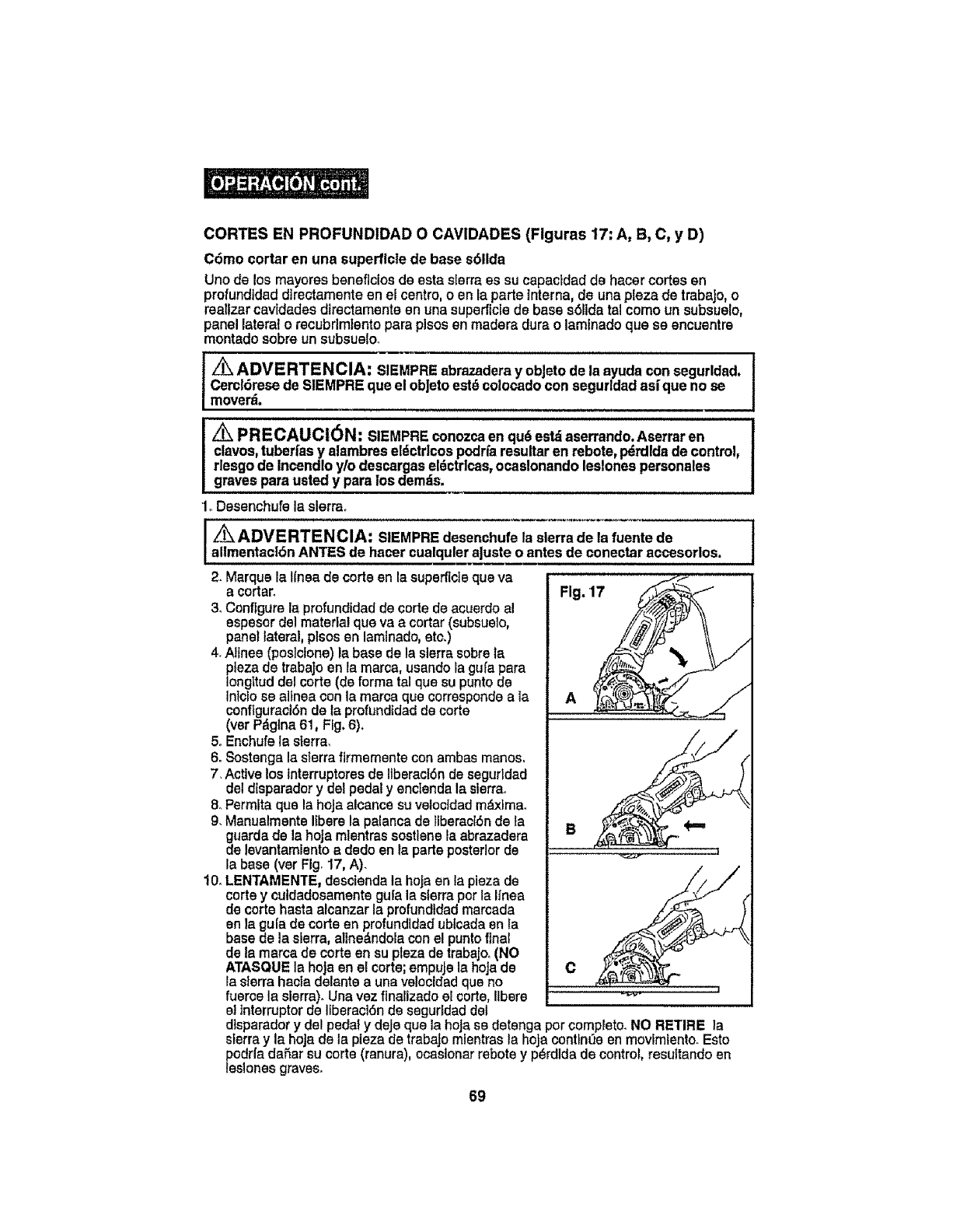
CORTES EN PROFUND1DAD O CAVIDADES (Flguras 17: A, B, C, y D)
Cdmo cortar en una superflcle de base s611da
Uno de losmayares beneflcios de esta sierra es su capacldad de hacer cortes en
profundldad directamente en el centre, o en la parle ]nterna, de una pleza de trabaJo,o
reallzar cavtdadss directamente en una superficte de base s6lidatal coma unsubsuelo,
panel lateral o recubrlmlentopara pleasen madera dura o laminado qua ss encuentre
montado sabre un subsuelo_
Z_ ADVERTENCIA: SIEMPREabrazaderayobjeto de la ayuda consegurldad.
Cercl6resede SIEMPRE quael ob|etoest_ eo!ocadoconsegurldadasfque no se
moverd.
Z_ PRECAUCl6N: SIEMPREconozcaen qu6est_ aserrando.Aserraren
clavos,tuberfasy alambreseldctdcospodrfaresultaren rebate, p_rdldade control_
rlesgode Incendtoy/o descargaseldctrlcas,ocaslonandoleslonespersonales
gravespara ustedy para losdemds.
'1. Desenchufe la sierra°
i _ADVERTENCIA: SIEMPRE desenchufe la sierra de la fuente de
altmentacl6n ANTES de hacer cualquler ajuste o antes de conectar accesorlos=
2. Marqua la tfnea de carte en Is superflcle qua va
acertar. Fig. 17
3. Configure la profundidad de carte de acuerde al
espeser del material que va a cortar (subsuelo,
panel lateral, plsos en lamlnado, ate.)
4_Alines (poslclene) la base de la sierra sabre la
plaza de trabaJo an la marca, usando ta gufa pera
Iongttud del certe (de forma ta! que su punto de
Intcio se altnea con la marca que cerresponde a la
conftguraciSn de la profundtdad de certe
(ver Pdglna 61, Fig. 6),
5. Enchufe la sierra.
6oSostenga la sierra firmaments cen ambas manes.
7_Active los Interruptores de ItberaclSn de segurldad
del disparador y del pedal y enclenda la sierra,,
8oPermEta qua la heJa alcance su vetecldad m_xfma,
9. Manualmente Ifbere la palanca de llberaciSn de la
guarda de la hoja mlentras sostlane la abrazadera
de levantamlento a dede en fa pads posterior de --t
la base (ver Fig, 17, A).
!0° LENTAMENTE, desclenda la hoja en la plaza de
certe ycutdadesamente gufa la sierra per la Ifnea
de carte hasta alcanzar la profundtdad marcada
en la gula de certe en profundidad ublcada en ta
base de la sierra, allne&ndola con el punto final
de la marca de carte en su plaza de trabajo° (NO
ATASQUE la hoja en el carte; empuje la hoJade
la sierra hacla delante a una velecidad qua no
fuerce la sierra)° Una vez flnallzado el carte, ltbere -_
el Interrupter de Ifberacl6n de sagurldad del
dtsparador ydel pedal ydeje qua la heJa se detenga par cempleto. NO RETIRE la
sierra y la heJade la pieza de trabajo mientras la hoja centlnee en movlmfanto+ Esto
pedrfa daSar su carte (ranura), ocastonar rebate y p_rdlda de control, resultando en
leslones graves.
69
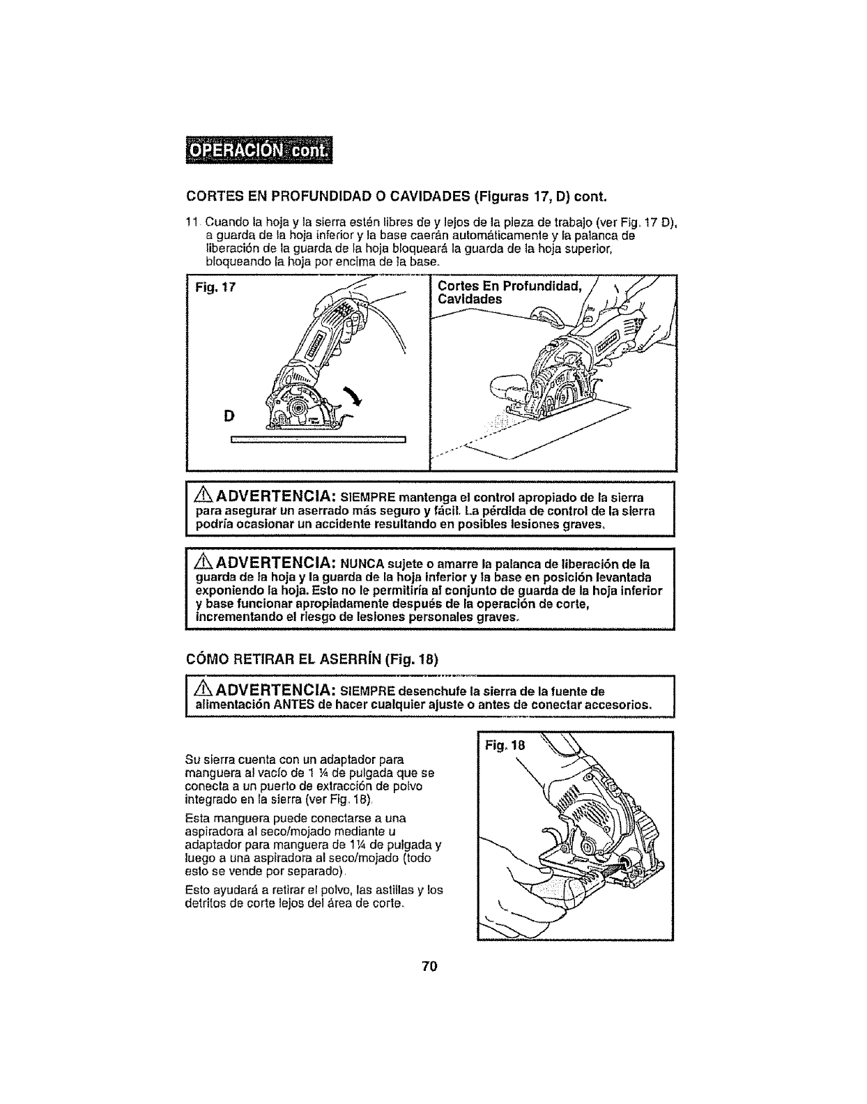
CORTES EN PROFUNDIDAD 0 CAVIDADES (Figuras 17, D) cont.
11 Cuando la hoja y la sierra est_n iibres de y lejos de la pieza de trabajo (vet Fig..17 D),
a guarda de ta hoja inferior y ta base caer&n au_om&ticamenle y la palanca de
fiberaci6n de la guarda de ta hoja bloquear_ la guarda de la hoja superior,
bloqueando la hoja por encima de ta base.
Fig. 17 Cortes
Cavldades
i_i _ .... _ _ _7
/_k ADVERTENCIA: SIEMPRE mantenga el control apropiado de la sierra
para asegurar un aserrado m_s seguro y f_cll. La p_rdfda de control de la sierra
podfia ocasionar un accidente resultando en posibles lesiones graves°
=,='==,,HH===H=H'= = = = =
Z_ ADVERTENCIA; NUNCA sujete o amarre la palanca de liberaci6n de la
guarda de ta hoja y la guarda de la hoja inferior y ta base en posici6n levantada
exponiendo la hoja. Esto no le permittfia a! eonjunto de guarda de la hoja inferior
y base funcionar apropiadamente despu_s de la operaci6n de corte,
Incrementando el rlesgo de leslones personales graves.
COMO RETIRAR EL ASERRiN (Fig. 18)
i1
Z_ADVERTENCIA" SIEMPRE desenchufe la sierra de la fuertte de
alimentaci6n ANTES de hacer cualquier ajuste o antes de conectar accesorios.
Su sierra cuenta con un adaptador para
manguera al vacio de 1 ¼ de pulgada que se
conecta a un puerto de extracciSn de polvo
integrado en la sierra (ver Fig 18),
Esta manguera puede conectarse a una
aspiradora al secoimojado mediante u
adaptador para manguera de 1_,¢de pulgada y
luego a una aspiradora al seco/mojado (todo
esto se vende por separado).
Esto ayudar_ a retirar ef pe_vo,las astillas ylos
detrites de corte lejos del &rea de corte.
70
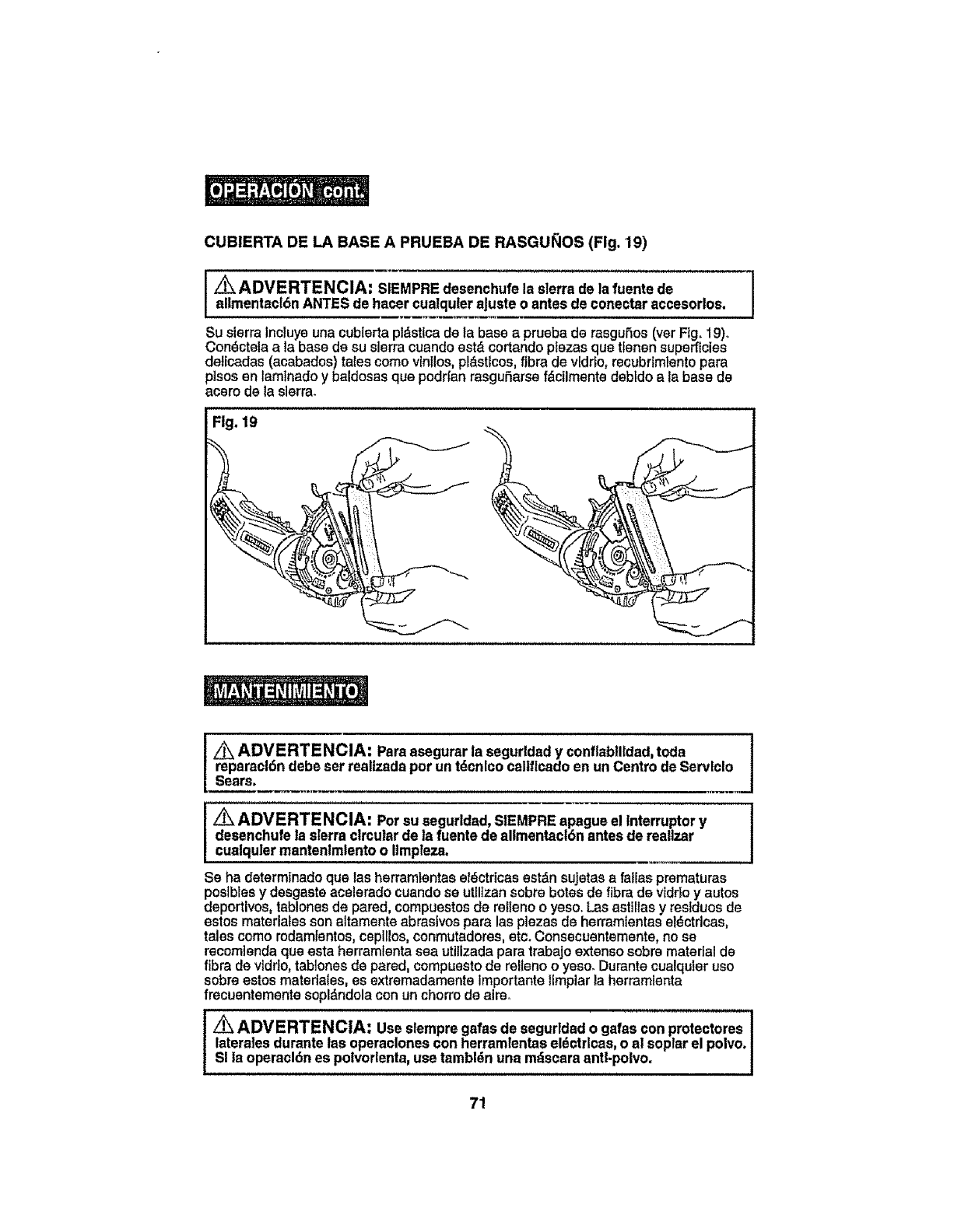
CUBIERTA DE LA BASE A PRUEBA DE RASGU_OS (Fig. '19)
Z_ ADVERTENCIA: SIEMPRE desenchufela sierra de la fuente de I
allmentact6nANTES de hasercualqu|eraJusteo antes de conectaraccesorlos. I
Su sierraIncluye una cublerta pldstica de la basea prueba de rasguSes (ver Ftg+19)+
Condctela a la base de su sierra cuando estd cortando plazas qua tlenen superficies
deticadas (acabados) tales come vtnllos, pldstlces, fibrade vidrfo, recubdmlento para
p]sos en tamlnado y baldosas qua podrfan rasguSarse fdcilmente debldo a la base de
scare de la slerra_
Fig, 19
J
I Z_ ADVERTENCIA: Parsasegurar la segurldady conflsbllldad,toda
reparacl6n debeset reallzadapot un tdcnlcocaltflcadoen unCentre de Servlclo
Sears,
_ADVERTENCIA: Persu segurldad,SIEMPRE apague el Interruptery
desenchufela sierra circular de la fuentede allmentacl6n antes de reallzar
cualqulermantenlmlentoo itmpteza.
Se ha determinado que las herramfentase_ctricas estdn sujetas a fallas prematuras
postbles y desgaste acelerado cuando se utlltzan sobre betas de fibra de vldrioy autos
deportivos, tablones de pared, compuestos de reUenoo yeso+Las astillasy residues de
estos materlales sen altamente abrasives para las piezas de herramientas eldctricas,
tales come rodamlentos,cepillos, conmutadores, etc. Consecuentemente, no se
recomlenda que esta herramlanta sea utillzada para trabajo extenso sabre matedal de
fibra de viddo, tablones de pared, compuesto de relleno o yesooDurante cualquier use
sobre estos materlates, es extremadamente Importante llmplar Jaherramlenta
frecuentemente sopldndola con un chorro de aireo
/_kADVERTENCIA: Use slempre galas de segurldado galas con protectores
lateralesdurante las operaclonescon herramlentasel_ctrlcas,o al sonar el poivo.
SI la operacldnes polvorlenta,use tambldnuna mdscaraant|-polvo.
71
MANTENIMIENTO DE RUTINA
ii, ,111111,1,11111,ii i
Z_ ADVERTENCIA: NO permitsen nlngdnmomento que fluldo de frenos, i
gasoline,productos a base de petr61eo,aceltes penetrantes,etc. entren en !
contactocon las plazas pldstlcas,Losqufmlcospuedendafiar,debllltsr o destrulr
el pldstlco,Iocuel podrfsresultaren leslonespersonales graves.
,,,,,,,,,,,,,,,,,,,,,,l,=,, ,,,=,= , = ,,,,,,,,,,,,, , ,,,,,,
El mantentmlento peri6d]cofacilfts unalarga vlday una opsracl6n libra de problemas.
Mantenga un cronograma de llmptado, lubrlcaciSny mantentmlento.Como pr&ctica de
mantenlmlento preventivo comOn,slga los slgulentes pasos sigulentes:
Z_ ADVERTENCIA: Parssu segurldad,SIEMPRE apague el Interrupter y I
desenchufeIs sierra de la fuentede allmentacl6nantes de reallzar cualquler I
.....mantenlmtentoo Ilmpleza.
1. Una vez flnalizadoet trabajo, limplela herramientapara permltirunbuen
funcionamlento de la herramientaaIolargodeltiampo.
2. Use patios limptosy humsdos para limpiarla herramlentao
3.Vertftqueel estadode todosloscablesel_ctdcos.
4. Mantengalas aberturas de afredel motorIlbresde acelte,grassy aserrfno astllias de
madamy guardsla herramtentaen untugar seco..
5. AsegL1resede qua todastas pfezasm6viles est_n bten lubdcadas,particularmente
despu_s de unaexpostclSnlargaa condfclonesde humedad y/o sucledsd.
LUBRICACION
Todo rodamtsnto en esta hermmlenta ha sido lubrlcadosuficientemanteconun
lubricants de alto grado para toda la duracl6n de la vlda OtUde la harramlenta baJo
condlciones de operaciSn normal°Por [otanto, no se requiem de IubrtcaclSnadtcionaL
72
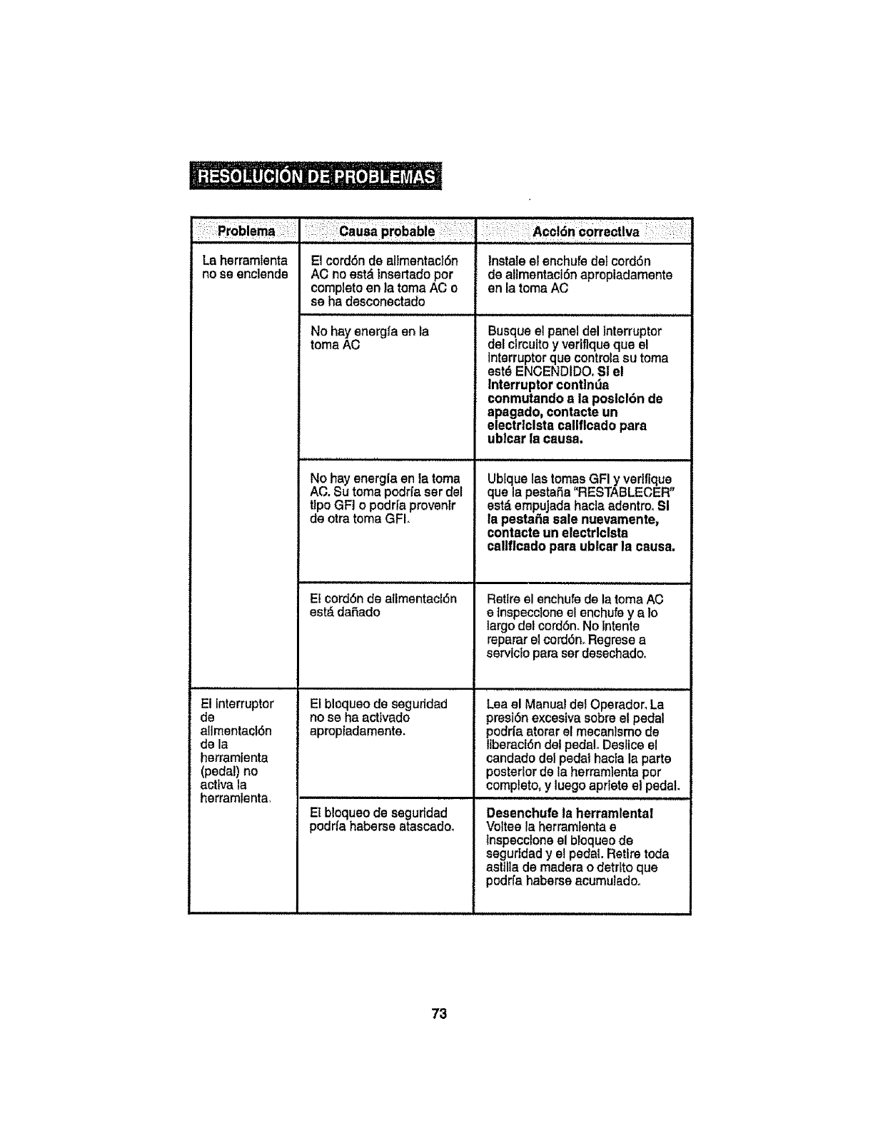
La herramlenta
no se enclende
El Interrupter
de
alimentacl6n
de la
herramlenta
(pedal) no
acttvala
herramlenta,
El cord6nde altmentacl6n
AC noest& tnsertado per
completeen la tomaACo
se ha desconectado
No hay energfa en la
toma AC
No hay energlaen la toma
AC. Su toma podrfa ser del
tIpoGFI o podr{a provenlr
de otra toma GFI,
i,, ,,,,,H I,,lll,llll,, Ill l Illl
Ef cord6nde atlmentacl6n
est&dafiado
El bloqueo de segurtdad
no se ha acttvado
apropiadamente.
El bloqueo de seguridad
podrfahaberse atascado.
Instaleel enchufe del cord6n
de altmentaci6n apropladamente
en la toma AC
Busque el paneldel Interrupter
del clrcuitoyvertflqueque el
Interrupterque controlaeu toma
est6 ENCENDIDO, SI el
Interrupter continua
eonmutandoa ia poslcl6n de
apagado, contacte un
electrlclsta callflcado para
ublcar la causa.
Ublque las tomas GFI y verlfique
que la pestafia"RESTABLECER"
est_ empujadahacla adentro,Sl
la pestaSa sale nuevamente,
contacte un electrlclsta
caltflcado para ublcarla causa.
Retireel enchufede latoma AC
e tnspeccloneel enchufeyaIo
largo det cord6n.Notntente
repararel cord6n.Regresea
servlctopara serdesechado.
Lea el Manual del Operador. La
presl6nexcestvasobreel pedal
podr|aaterar el mecanismo de
liberaci6n detpedal.Desliceel
candadodel pedal hactala parte
posteriorde la herramlenta per
complete,y luegoaprteteel pedal.
Desenchufe la herramlental
Volteela herramlentae
tnspecctoneel bloqueode
segurldad y el pedal. Retire toda
asttlla de madera o detrito que
podrfa haberse acumulado,
73
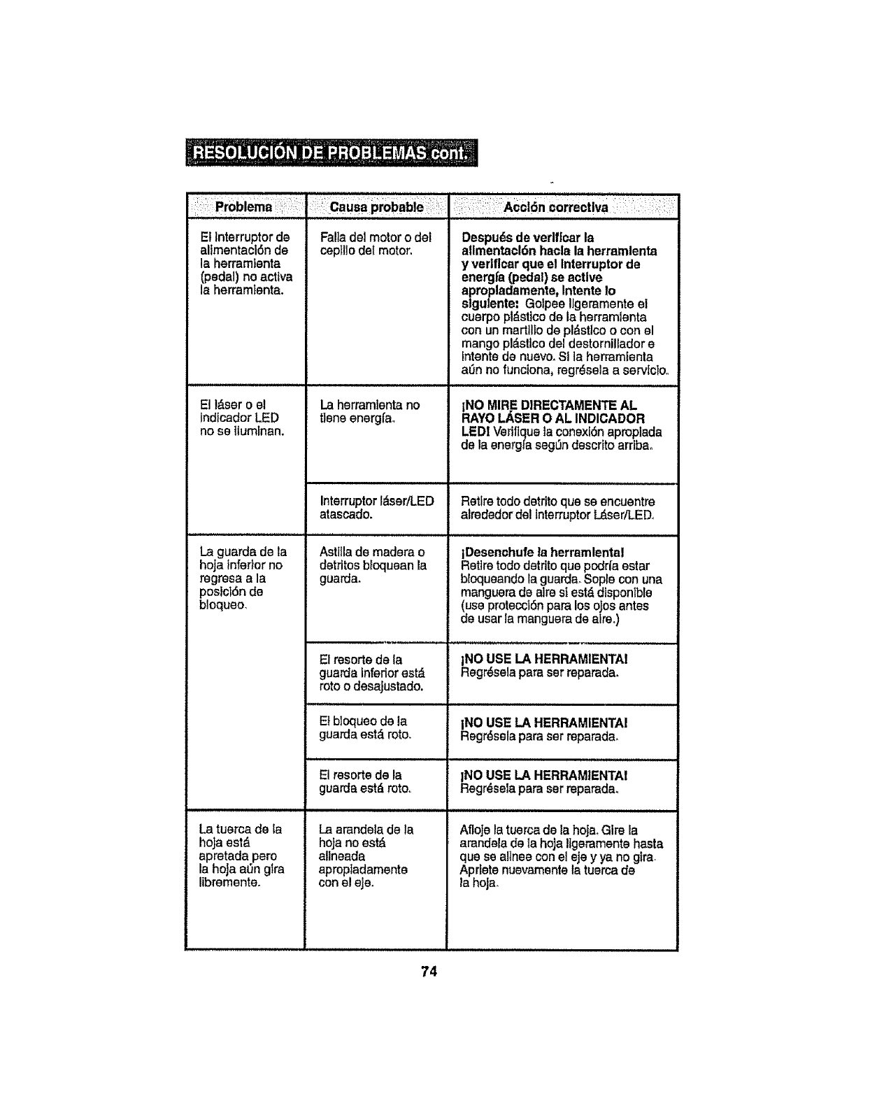
El lnterruptor de
allmentacl6n de
la herramlenta
(pedal) no active
la herramtenta.
El l&ser o el
lndIcador LED
no se itumFnan.
La guarda de la
hoja inferior no
regresa a la
posid6n de
bloqueo.
La tuerca de la
ho]a est_
apretada pero
la hoja ann glra
libremente.
Falladel motoro del
ceptllo det motor.
La herramientano
ttsne energfa.
InterruptorI_,ser!LED
atascado.
Ast]lla de madera o
detrltos btoquean la
guarda.
El resorts de la
guarda inferiorest&
roto odesajustado.
,,,,H ,,H H, ,
El bloqueo de la
guards est_ roto,
El resortede Ia
guardaestd roto.
Laarandelade la
hoJano est_
atlneada
aproptadamente
conel eje.
Despu_sde verlflcar la
allmentacl6nhaole la herramlenta
y verlflcar quael fnterruptor de
energ[a (pedal)se active
apropladamente,Intents Io
slgulente: Golpee!lgemmenteel
cuerpopiPet!code la herramlenta
con unmartlllo de pl&sttcoo con el
mangopl_stlcodel destomilledore
Intentsde nuevo,SI la herramlenta
a_n no funclona, regr_sela a servlolo.
i,,,i,i,l,,ll, HHH,HH,
INO MIRE DIRECTAMENTEAL
RAY{:)LASER O AL INDICADOR
LED!Verlflqueta conexf6naproplada
de la energla seg_n descrttoarribao
Retiretodo detrito qua se encuentre
alrededordet tnterruptorL&sertLEDo
IDesenchufe la herramlental
Retiretodo detrtto qua podrla ester
bloqueandolaguardaoSepiaconuna
manguerade aimst est,.disponTble
(use protecct6npare los ojos antes
de user la manguerade airs°)
_NOUSE LA HERRAMIENTAI
egr_selapareser reparada,
INO USE LA HERRAMIENTA!
Regr_selapareset reparada_
!NO USE LA HERRAMIENTA!
Regrdselapara serreparada,
AfloJela tuercade la hoJa_Glre la
amndela de la hoja Ilgeramentehaste
qua se alines con el sje yya no glra_
Aprlete nuevamentela tuercade
la hojao
74

IL_ ADVERTENCIA: El use de conexlonesy accesorlosque no estdn ]
recomendadospare esta herramlentapodrfanset pellgmsosy podrfanresultaren I
leslonesgraves.
Las tiendasSears yotresdlstrlbuldores Craftsmancuentan conla hoJade acero de
diamantede 3 puigadas (9-61273) para cortar baldosas de cer&mtcay m_rmolde haste
3/8 de pulgada de espesor conesta sierra.
Las hoJasde repuesto tambl_n est&ndisponibles pare Ia hoja de acerode 3pulgadas,
20 dientes con puntade carburo pare cotter madera /use general (9-61272) marca
Craftsman®que vlene con la sierra.
Vtslte su tiendaSears local u otrodfstribuldor Craftsman ovlsite sears.comlcraftsmano
75
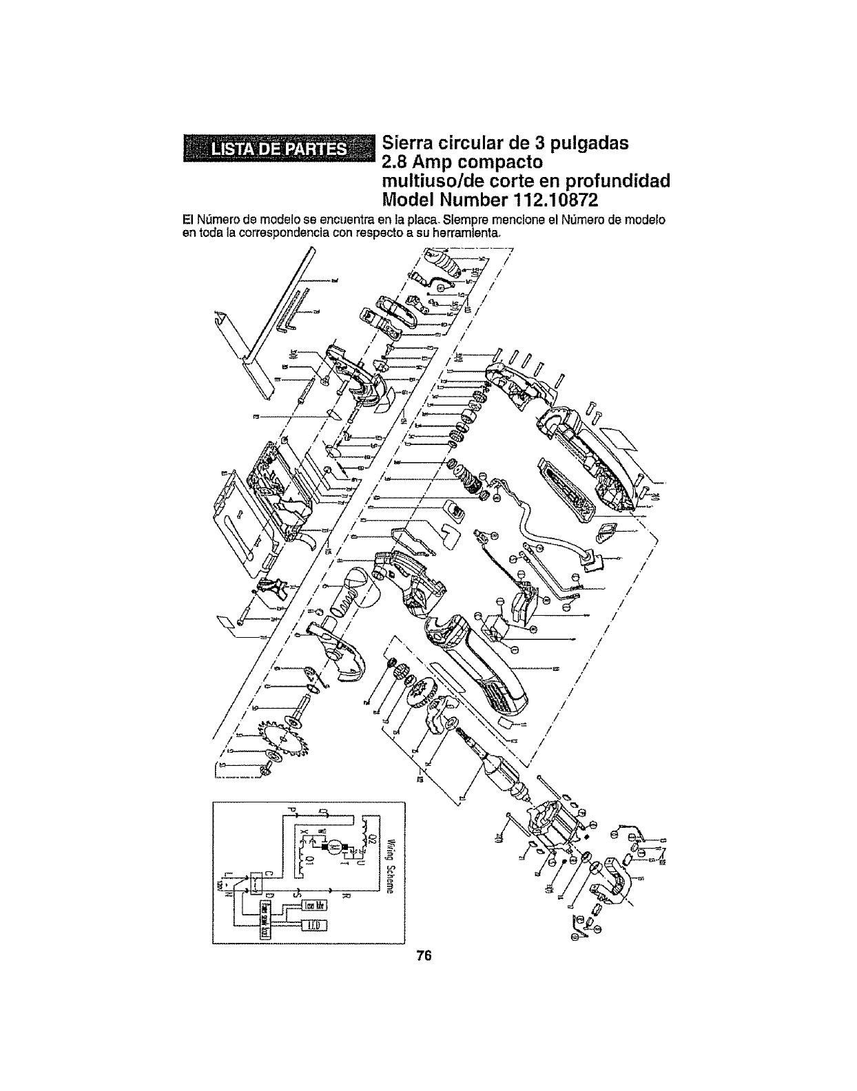
Sierra circular de 3 pulgadas
2.8 Amp compacto
multiusotde corte en profundidad
Model Number 112.10872
El N_mero de modelo se encuentra en la placa. Slempre mencione el N_mero de modelo
en toda la correspondencia con respecto a su herramtentao
/
ii
/
/
76

Sierra circular de 3 pulgadas
2.8 Amp compacto
multiusolde carte en profundidad
Model Number 112.10872
El N_mero de modelo se encuentra en laplaca.SFempremenctone el N_3merode modelo
en toda la correspondencia con rex )ectoasu herramlentao
Arl_culo No. Partes No. Descrtpcl6n de la parte
1 300801 ......E!iqueta. clasif!cada
2300358 Tornlllo autorrascable ST4,2X16
3 3780015 Bastidor derecho
0 601743
4 Incluyo
5 tncluyo..
6 tnclub!...9=
7 InCtuyo
i i B.......... 601749
9
10
18
tl
t2
13
14
t5
tncluyo
Incluyo
Incluyo
300744
300788
3780014
tncluyo
Incluyo
Cant.
1
4
1
Montaje de Unidad Dtsparador 1
Taps 1
.. Bot6n de qtrsr ...........................i ......
Rosette de Compresi6n 1
Rasept&culo de Peri_fa 1
Conjunto de cables de alimentaCi6n 1
...................................................... ]
Protector de cable 1
Unea Interne I20 (azul) 2
Csbte..!n.!e.rno60 (marr6n) 2
coniu,n,!,o,dePCB 1
Interrupter 1
Bas!!,do,[,!z,qufe[d# , , 1
Etiquets t ....................... 1
Etiqueta de la marca 1
t0t 300767 Juego de escobiIlas carbonos
t7 Incluyo ConJunlo de escobtl_as .....
t6 tnc!uyo S_orte del cetp__
102 810744 Mon!aje de! motor
19 !nc!uyo Soporte trasero
20 lncluyo Manguito
21 .{ncluya Co]{netes de bolas"619/6-2Z
22
23
24
25
28
27
28
29
3O
31
32
33
34
35
2
2
2
1
1
1
1
tncluye Tuerca M3 2
inc_eyo
tncluyo
tnctuyo
tncluv,_
!nc_uyo
!nctuyo
tnc!uy0
Incluyo
Incluyo
Incluyo
300768
300751
300799
Con)unlo d e _,,,,_'5,!,8 !,p,f, , ,
Cojinete
Tornlitos con standers M3X45
Armadura
CoJlnele de bolas 61600-2ZJC3
Soporte frontal ...............................................
Ventilador
CoJtnete de bolas 619/9-2Z
Ant_tode toterancia
Seflante C0170 TC 9X 17X4
TornIllo M4X20
Taps de csja de csmbtos
SeUante 10675 TC 6 X 15 X 4
1
4
2
1
1
1
1
1
1
1
7
1
1
36 300796 Anf!!o Ce t!po E 5
37 300753 Antllo de tolersncta
38 300795 C£jin#te de bolas 62819.2ZJC3
39 300793
40 300798
41 300740
1 601750
42 tncluyo
43 !nc{uyo
44 incluyo
45 fncIuyo
48 induyo
.........EngranaJe helicoidal
Se_lante
Ani[lo de toieranc_a
Montaja eje encjranajes heliceidales
Cgj!nete de ,bolas 634-2Z/C3
Eje heftco!dal
Engranaje
Cojinete de bolas 824-2Z
Anltlo de tolerancta
1
2
2
1
1
1
1
I
1
1
1
t
77

Sierra circular de 3 pulgadas
2.8 Amp compacto
muitiuso/de carte en profundidad
Model Number 112.10872
El N_mero de modelo se encuentra en la place°Stempre menclone el N0mero de modelo
en toda ta correspondencia con res
Artfculo No,
47
46
49
51
52
53
54
55
55
57
Partes No,
375(3024............
3780019
300797
300752
3780025
300781
300761 .................
300764
300773
300794
300800
58 300750
59 300749
103 601747
60 incluyo
6i ]ncluyo
63 Incluyo
64 incluyo
65 tncluyo
66 tncluyo
67 tncluyo
oecto a su herramlentB.
Descrlpei6n de la parte .Cant
....Patanca del interrupter 1
Corredera ,!.................
Junta t
Basttdor de engranaje I
Tube asp,!rador de polvo t
TuBrce M4 I
.......Guard a inferior 1
Resorte de torsion I
Antllo de retenci_n 17-A I
........._,rb,_F,, 1
Hoja de siq,r[a.......................... t
Bdda exterior 1
TernIllo 1
Monta}e de Unidad L&ser 1
Tape de,,!,_serII 1
Torntl!oaulorroscable ST2.2X6 3
Untdad L_ser y LED ............................... 1,
Tarntl{o M3X4 1
TorntIlo autorrosoable ST2.gx6 2
Soporte del tub,o,,!a,s,er 1
........soporte, 1
soporte laser ........ 1
104 601746 Montaje de guardas supsri_i_ ............... "---i--"-
68 tncluyo
69 .... tncluyo
70 lncl_ .............
7t incluyo
72 incluyo
73 inctuye
74 Incluyo
75 tnciuyo
68 incluyo
105 601753
76 tnctuyo
77 !nc!uyo
78 Jncluyo
79 lncluyo
80 incluyo
81 tncluyo
82 incluyo
83 incluyo '
54 300774
85 300776
, 86,, 300777
Clevija dei eje
Arandela del resorte
A_aptador
Guarda superior
Etiqueta VI
............Apuntador
BotSn de lava
Arttcufecibn de resorte 2,5X18
iEtiqueta V
Montaje de fa Base
Etiqu,e!,a,II
TornIlfo M5X6
Et!queta !11
Unidad pare so_dar la base
Clavija def sopode
Resorte
Pe,rnq........................
Etiquela VII
Conjunto de escatas
Llave,,,!ng!e,sa
Tornlllo
67 . 300788 . Perno
89 3780029 Tablero protector
90 300783 Manualde30perador
1
1
1
1
1
1
1
1
1
1
1
I
1
1
1
1
1
i
2
1
1
2
1
78

79

.....':i¸!:'!i¸_:I:'::I!=_'__i,i' i¸:!:I:_:¸_i!:ii!_:¸/ _;:i¸'::i_!:'_ il:_":i: i ¸:;:'_i_:_:i _i i i_i::i'i-::ii¸::I!:_iiT_'_i ii:__'ii!::i'i::iii_i'¸,i_'__ii]__:__
ii_iiii_:i_i_!:!_i!i:i_i_:'_i:ii:!'_:_ ::_:_:iiiii!ii_:i_i_:i!_!:i!_:_!il_:_i_::%¸¸¸¸i_i_i_!/i_!ii _!iiiii_ii i¸i!i/_!i_!i_i_ii:ii/_ii!i;i_il;!!!i_i!;_
: ; Get it fixed, at your home or ours.
Your Home
: : For repair - In your home -of all major brand appliances,
lawn and garden equipment, or heating and coolingsystems,
i :i: _ii
iii_!ii
i
!_i,ii
i ¸:_!i
no matter who made It, no matter who sold Itl
For the replacement parts, accessories and
owner's manuals that you need to do*-it-yourself.
For Sears professionalinstallationof home appliances
and items like garage door openers and water heaters.
1-800-4-MY-HOME ®(I.800.469.4663)
Callanytime,dayorntght(U.&A°andCanada)
WWW_888rS_COm Www,8_r8_ca
For experthomesolutionsadvice:www.managamyhomoocom
:iiii:!il
Our Home
For repair of carry-in items like vacuums, lawn equipment,
and electronics, call or go onqlne for the location of your nearest ,
Sears Parts & Repair Service Center
1-800-488-1222 (U,&A,) 1-800.4694663 (Canada) ?[
Cal_anytime,day ornight ;: !
www, se_ar_,,corn www_saarLc8 ....
r
i!
iii
To purchase a protection agreement on a product serviced by Sears:
t-800-827-6655 (U,S,Aj 1-800-361-6665 (Canada) ........
Au Canada pour service an fran_als: ....
1-800-LE-FOYER Mc _i
i
(I_00-533-6937) ,_:
ii
Para padfr sarvlclode reparaclSn
a domlci[[o,ypara ordenarptazas:
1-888-SU-HOGAR ®
(1-888-784=6427)
®R#gl#_d T_dem_rk I_ Tm_ert_rk 1=u _t_= Mark at _er_ B_=, LLC
®Memo F_g[_trad_t_M_n_ do F_brk_!==Mn_ d_ _rvl_to de _r_ Brard_ LLC
tzo
M_rq_ d_ ,_mrn_rt_ f M_rqu=,d6po_e do r_e_,r_Bra_, LLC O _r_ I_randl, LLC
