Craftsman 113206891 User Manual 6 1/8 INCH JOINTER PLANER Manuals And Guides L0905111
CRAFTSMAN Jointer/Planer Manual L0905111 CRAFTSMAN Jointer/Planer Owner's Manual, CRAFTSMAN Jointer/Planer installation guides
User Manual: Craftsman 113206891 113206891 CRAFTSMAN CRAFTSMAN 6-1/8-INCH JOINTER-PLANER - Manuals and Guides View the owners manual for your CRAFTSMAN CRAFTSMAN 6-1/8-INCH JOINTER-PLANER #113206891. Home:Tool Parts:Craftsman Parts:Craftsman CRAFTSMAN 6-1/8-INCH JOINTER-PLANER Manual
Open the PDF directly: View PDF ![]() .
.
Page Count: 32
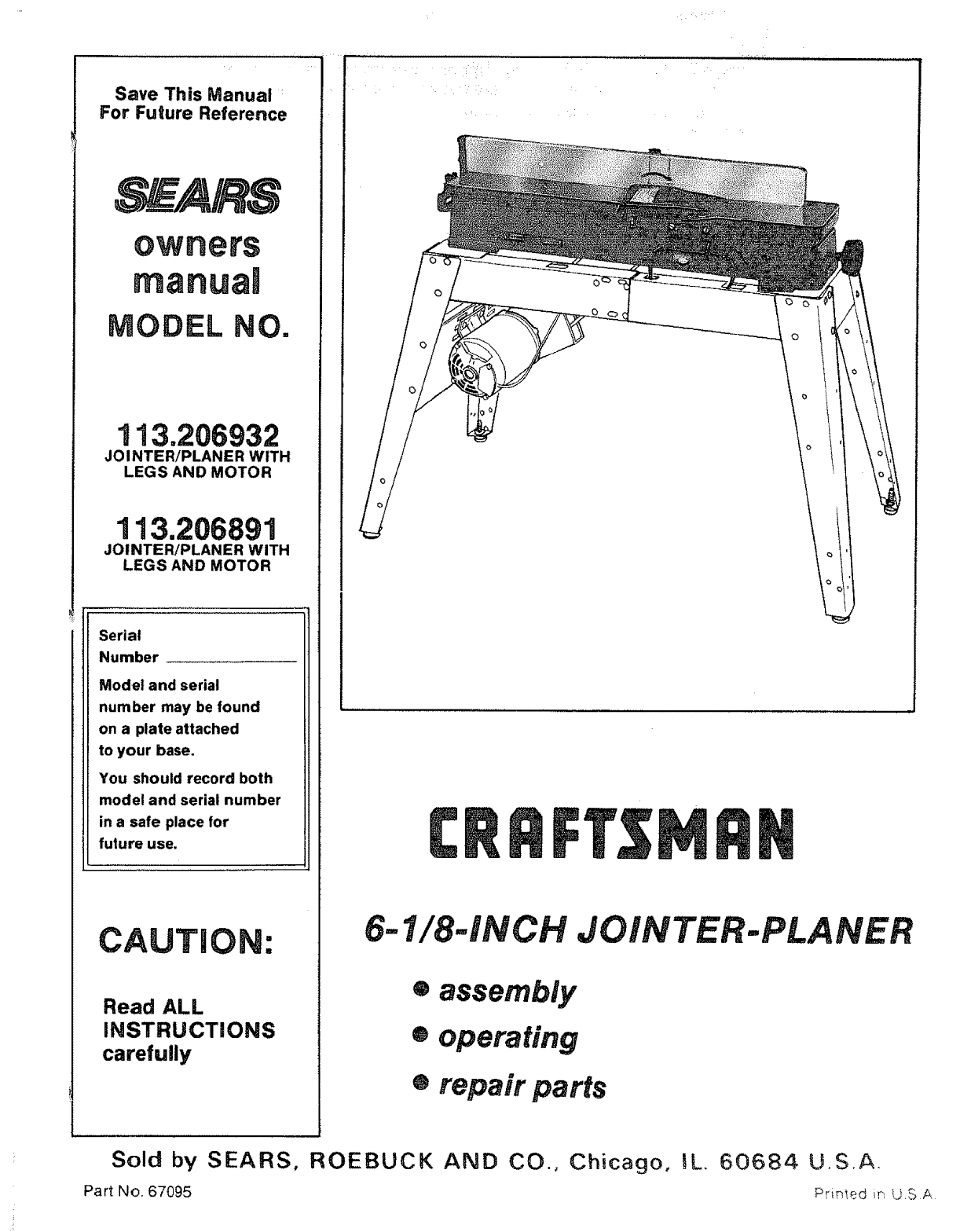
Save This Manual :
For Future Reference
owners
rnanua!
MODEL NO.
113.206932
JOINTER/PLANER WITH
LEGS AND MOTOR
113.206891
JOINTERiPLANER WITH
LEGS AND MOTOR
Serial
Number
Model and serial
number may be found
on a plate attached
to your base.
You should record both
model and serial number
in a safe place for
future use,
CAUTION:
Read ALL
iNSTRUCTiONS
carefully
6-1/8-iNCH JOINTER-PLANER
®assembly
®operating
•repair parts
Sold by SEARS, ROEBUCK AND CO., Chicago, _L. 60684 U,S.A.
Part No. 67095 Primed iN US A

.
eneraisafety instructions for
1. KNOW YOUR POWER TOOL
Read and understand the owner's manual and
fabels affixed to the tool Learn its application
and limitations as well as the specific potential
hazards peculiar to this tool. 13.
2. GROUND ALL TOOLS
This tool is equipped with an approved
3-conductor cord and a 3-prong grounding type
plug to fit the proper grounding type receptacle. 14.
The green conductor in the cord is the g rounding
wire. Never connect the green wire to a live 15,
.... .....terminal.
•3. KEEP GUARDS IN PLACE,
:in working order, and in proper adjustment and
alignment. 16.
4. REMOVE ADJUSTING KEYS AND WRENCHES
Form habit of checking to see that keys and
adjusting wrenches are removed from tool before 17.
turning it on.
KEEP WORK AREA CLEAN
Cluttered areas and benches invite accidents. 18.
Floor must not be slippery due to wax or sawdust,
AVOID DANGEROUS ENVIRONMENT
power tooas
safety glasses. Also, use face or dust mask if
cutting operation is dusty, and ear protectors
(plugs or muffs) during extended periods of
operation.
SECURE WORK
Useclamps ora vise to hold work when practical.
It's safer than using your hand, frees both hands
to operate tool.
DON'T OVERREACH
Keep proper footing and balance at all times.
MAINTAIN TOOLS WITH CARE
Keep tools sharp and clean for best and safest
performances. Follow instructions for lubricating
and changing accessories.
DISCONNECT TOOLS
before servicing; when changing accessories
such as blades, bits, cutters, etc.
AVOID ACCIDENTAL STARTING
Make sure switch is in "OFF" position before
plugging in
USE RECOMMENDED ACCESSORIES.
Consult the owner's manual for recommended
accessories. Follow the instructions that accom-
Don't use power tools indamp or wet locations or: party the accessories. The use of improper acces-
....... expose them to rain. Keepw0rkamawel!lighted:. i:::: sories may cause hazards.
Provide adequate surrounding workspace 19_ NEVER STAND ON TOOL
:i : 7, KEEP CHILDREN AWAY ........ Serious injury could occur if the tool is tipped or
: All visitors should be kept a safe distance from _ if the cutting tool is accidentally contacted. Do
work area. _ not store materials above or near the tool such
8, MAKE WORKSHOP CHILD,PROOF that it is necessary to stand on the tool to reach
with padlocks, master switches, or by removing _ i them.
:starter keys. ::i_:_ii:ii 20iCHECK DAMAGED PARTS
9. DON'T FORCE TOOL ::Before further use of the tool, a guard or other
It will do the job better and safer atthe rate for partthat is damaged should be carefully checked
which it was designed, to ensure that it will operate properly and perform
10.
11.
12.
Z87.1) at all times. Everyday eyeglasses only
have impact resistant lenses, they are NOT
USE RIGHT TOOL
Don't force tool or attachment to do a job it was
not designed for.
WEAR PROPER APPAREL
Do not wear loose clothing, gloves, neckties Or
jewelry (rings, wrist watches) to get caught in
moving parts Nonslip footwear is recommended.
Wear protective hair covering to contain long
hair. Roll long sleeves above the elbow.
USE SAFETY GOGGLES (Head Protection)
Wear Safety goggles (must comply with ANSI
21.
22.
its intended function. Check for alignment of
moving parts, binding of moving parts, breakage
of parts, mounting, and any other conditions that
may effect its operation. A guard or other part
that is damaged should be properly repaired or
replaced.
DIRECTION OF FEED
Feed work into a blade or cutter against the
direction of rotation of the blade or cutter only.
NEVER LEAVETOOL RUNNING UNATTENDED :
Turn power off. Don't leave tool until it comes toi:
a complete stop.

:: _: _:i¸¸i¸¸:¸ii: ,: i: :: _;:
additional safety instructions
Safety is acombination of operator common sense and
alertness at all times when the Jointer-Planer is being
used.
WARN|NG: FOR YOUR OWN SAFETY, DO NOT AT-
TEMPT TO OPERATE YOUR JOINTER-PLANER UNT_IL
IT iS COMPLETELY ASSEMBLED AND INSTALLED
ACCORDING TO THE INSTRUCTIONS... AND UNT|L
YOU HAVE READ AND UNDERSTOOD THE FOLLOW-
ING.
PAG E
1. GENERAL SAFETY INSTRUCTIONS FOR POWER
TOOLS ..................................... 2
2. GETTING TO KNOW YOUR JOINTER-PLANER 11
3. BASIC MACHINE OPERATION ................ 17
4. USE OF HOLD-DOWN/PUSH BLOCKS ......... 18
5, MAINTENANCE ............................. 19
6. STABILITY OF MACHINE
If there is any tendency for the Jointer-Planer to tip
over or move during certain operations such as when
planing or jointing long heavy boards, the Jointer-
Planer (stand) should be bolted to the floor.
7. LOCATION
The Jointer-Planer should be positioned so neither
the operator nor a casual observer is forced to stand in
line with the wood while it is being planed.
This machine is intended for indoor use only. Provide
adequate lighting.
8. KICKBACKS
Kickbacks can cause serious injury. A kickback occurs
when the operator looses control of the workpiece
causing it to be kicked back toward him.
Kic_kbacks-and possible injury from them can usually
be avoided by:
a. Holding the workpiece firmly against tables and
fence.
b. Not taking too deep acut at one time. A deep cut
requires more effort to feed the wood while planing
and can cause the wood to kickback. A cut between
t/32 and 1/16 of an inch deep will produce the best
results.
C.
d.
Not jointing, planing, or beveling pieces of wood
smaller than recommended. (See section in this
manual, "Basic Jointer-Planer Operations.")
Smaller pieces of wood can tip over on the tables,
or into the cutter head and can be kicked back
toward you.
Keeping blades sharp. Blades that are dutl or
nicked require more effort while planing and will
tend to pound the wood rather than cut it, which
can cause the wood to kickback. A nicked blade will
cut aridge in your wood and cause the wood to ride
upon the outfeed table. Make sure the cutter blades
are installed properly, and cutter blade wedge
screws are tight.
for jointer-planer
9. PROTECTION: EYES; HANDS, FACE, EARS, BODY
a. If any part of your jointer is malfunctioning, has
been damaged or broken . . . such as the motor
switch, or other operating control, a safety device
or the power cord.., cease operating immediately
until the particular part is properly repaired or
replaced.
b, Wear safety goggles that comply with ANSI Z87.1
and a face shield if operation is dusty. Wear ear
plugs or muffs during extended periods of operation.
c. Do not plane, joint, or bevel wood shorter than 12
in. Smaller pieces of wood can tip over on the
tables, or into the cutterhead and be kicked back
toward you.
d. Always use the hold down/push block when jointing
or beveling wood narrower than 3 in. but never joint
or bevel wood narrower than 3/4 in., or less than !/4
inch thick.
e. Always use the hold down/push blocks when
planing wood thinner than 3 in. but never plane
wood thinner than !/2 in. under any circumstances.
f. Avoid awkward hand positions, where asudden
slip could cause a hand to move into the cutters.
g. Neverturn yourJointer-Planer"ON" before clearing
the table(s) of all objects (tools, scraps of wood,
etc.) except for the workpiece and related feed or
support devices for the operation planned.
h. Make sure the cutterhead revolves in the right
direction, (toward the infeed table).
i. KEEP CUTTER GUARD IN PLACE AND OPERAT-
ING PROPERLY AT ALL TIMES. Regularly check
the tension of the cutter guard spring to assure
satisfactory operation. (See Getting To Know Your
Jointer-Planer section.)
j. Always feed the wood completely through the
cutter head and past the cutter guard so that the
guard returns to the rest position against the fence.
When using only one hold down/push block to feed
the wood, do not place your other hand on the
Jointer-Planer.
k. Always maintain complete control of the workpiece
and provide adequate support for long and heavy
workpieces.
10. Warped wood should be surface planed on the concave
side for best results.
11. To avoid arough planed surface, determine if possible,
which way the grain emerges from the wood and feed
the wood accordingly.
/#_ GRAIN EMERGING
ROTATION
12. Do not plane edges of plywood, composition materials,
or wood that has glue on it or is painted or varnished.
Planing these materials witl dull the blades quickly.
3
additional safety instructions for jointer-pUaner
i,
15: Never leave the Jointer-Planer work area with the
power on; before the Jointer-Planer has come to a
complete stop, or without removing and storing the
switch key.
16. Never operate the Jointer-Planerwith protectivecover
onthe unused shaft end of the motor removed.
17. Do not attempt to perform an abnormal or little-used
operation without study and the use of adequate hold
down/push blocks, jigs, fixtures, stops, etc.
18. DO NOT perform layout, assembly, or setup work on
the table while the cutting toot is rotating:
WARNING: THE 2" JOINTER-PLANER PULLEY AND
THE 2-1/2" MOTOR PULLEY FURNISHED WILL RUN
THE CUTTER HEAD AT APPROXIMATELY 4300 RPM
THAT A CARELESS FRACTION OF A SECOND IS
SUFFICIENT TO INFLICT SEVERE INJURY.
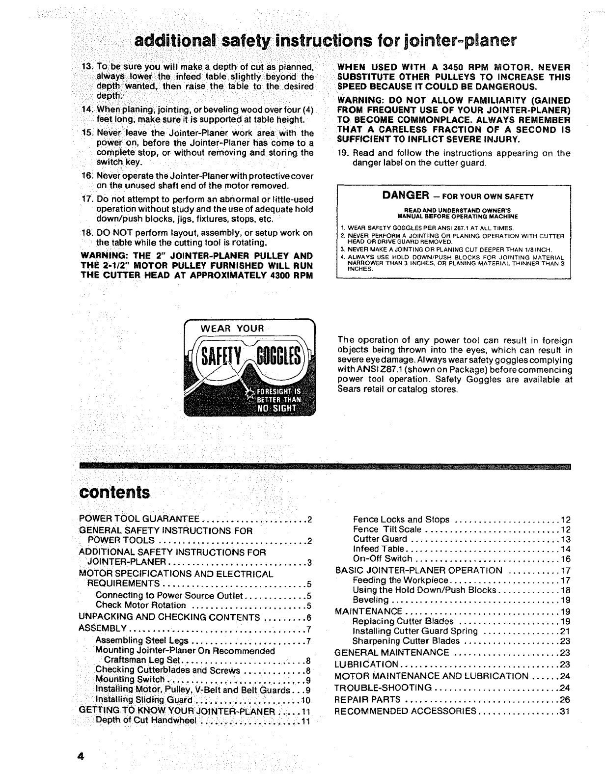
19. Read and follow the instructions appearing on the
danger label on the cutter guard.
DANGER - FOR YOUR OWN SAFETY
READ AND UNDERSTAND OWNER'S
MANUAL BEFORE OPERATING MACHINE
1. WEAR SAFETY GOGGLES PER ANSI Z87.1 AT ALL TIMES.
2. NEVER PERFORM A JOINTING OR PLANING OPERATION WITH CUTTER
HEAD OR DRIVE GUARD REMOVED.
3. NEVER MAKE A JOINTING OR PLANING CUT DEEPER THAN 1/8 INCH.
4. ALWAYS USE HOLD DOWN!PUSH BLOCKS FOR JOINTtNG MATERIAL
NARROWER THAN 3 INCHES, OR PLANING MATERIAL THINNE_ THAN 3
INCHES.
WEAR YOUR
The operation of any power too_ can result in foreign
objects being thrown into the eyes, which can result in
severe eye damage. Always wear safety goggles complying
with ANSl Z87.1 (shown on Package) before commencing
power tool operation. Safety Goggles are available at
Sears retail or catalog stores.
m' '_'_'
contents
POWER TOOL GUARANTEE ...................... 2
GENERAL: SAFETY INSTRUCTIONS FOR
POWER TOOLS ............................... 2
ADDITIONAL SAFETY INSTRUCTIONS FOR
JOINTER-PLANER ............................. 3
MOTOR SPECIFICATIONS AND ELECTRICAL
REQUIREMENTS .............................. 5
Connecting to Power Source Outlet ............. 5
Check Motor Rotation ........................ 5
UNPACKING AND CHECKING CONTENTS ......... 6
ASSEMBLY .............................. ....... 7
Assembling Steel Legs ........................ 7
Mounting Jointer-Planer On Recommended
Craftsman Leg Set .......................... 8
i Checking Cutterblades and Screws .............. 8
iMounting Switch. _.;, _._. ...... ...... .. :.......9
Insta_i|ng Mot0r, Pulley, V-Belt and Belt Guards ... 9
• installing Siidi'ng Guard_:..... ....... .. :. ...... 10
GETTING TO KNOW YOUR JO1NTER-PLANER _.... 11
DePt h of Cut Handwheel :! .. _.,..., ::. :. .... ,..tl
i ,
4ii
Fence Locks and Stops ...................... 12
Fence Tilt Scale ............................ 12
Cutter Guard ............................... 13
Infeed Table ................................ 14
On-Off Switch .............................. 16
BASIC JOINTER-PLANER OPERATION ........... 17
Feeding the Workpiece ....................... 17
Using the Hold Down/Push Blocks ............. 18
Beveling ................................... 19
MAINTENANCE ................................ 19
Replacing Cutter Blades ..................... t9
Installing Cutter Guard Spring ................ 21
Sharpening Cutter Blades .................... 23
GENERAL MAINTENANCE ...................... 23
LU BRI CATION ................................. 23
MOTOR MAINTENANCE AND LUBRICATION ...... 24
TR OUBLE-SHOOTI N G .......................... 24
REPAIR PARTS ................................ 26
RECOMMENDED ACCESSORIES ................. 31
motor specifications and
This machine is designed to use a 3450 RPM motor only.
Do not use any motor that runs faster than 3450 RPM. It is
wired for operation on 110-120 volts; 60 Hz., alternating
current. IT MUST NOT BE CONVERTED TO OPERATE
ON 230 VOLTS. EVEN THOUGH SOME OF THE RECOM-
MENDED MOTORS ARE DUAL VOLTAGE.
THESE CRAFTSMAN MOTORS HAVE BEEN
FOUND TO BE ACCEPTABLE FOR USE ON
THIS TOOL.
HP RPM VOLTS CATALOG NO.
t/2 3450 110-120 1216
1/2 3450 110-220 12!8
3/4 3450 110-120 t219
3/4 3450 110-120 1226
CAUTION: Do not use blower or washing machine motors
or any motor with an automatic reset overload protector as
their use may be hazardous,
CONNECTING TO POWER SOURCE OUTLET
This machine must be grounded while in use to protect the
operator from electric shock.
Plug power cord into a 110-120V properly grounded type
outlet protected by a 15-amp, dual element time delay or
Circuit-Saver fuse or circuit breaker.
If you are not sure that your outlet is properly grounded,
have it checked by a qualified electrician.
WARNING: DO NOT PERMIT FINGERS TO TOUCH THE
TERMINALS OF PLUGS WHEN INSTALLING OR
REMOVING THE PLUG TO OR FROM THE OUTLET.
WARNING: IF NOT PROPERLY GROUNDED THIS
POWER TOOL CAN INCUR THE POTENTIAL HAZARD
OF ELECTRICAL SHOCK. PARTICULARLY WHEN USED
IN DAMP LOCATIONS IN PROXIMITY TO PLUMBING, IF
AN ELECTRICAL SHOCK OCCURS THERE IS THE
POTENTIAL OF A SECONDARY HAZARD SUCH AS
YOUR HANDS CONTACTING THE CUTTING BLADE.
tf power cord is worn or cut, or damaged in any way, have
it replaced immediately.
PROPE R LY
GROUNDED
3-_RONG
PLUG
GROUNDING
PRONG
electrica! requirements
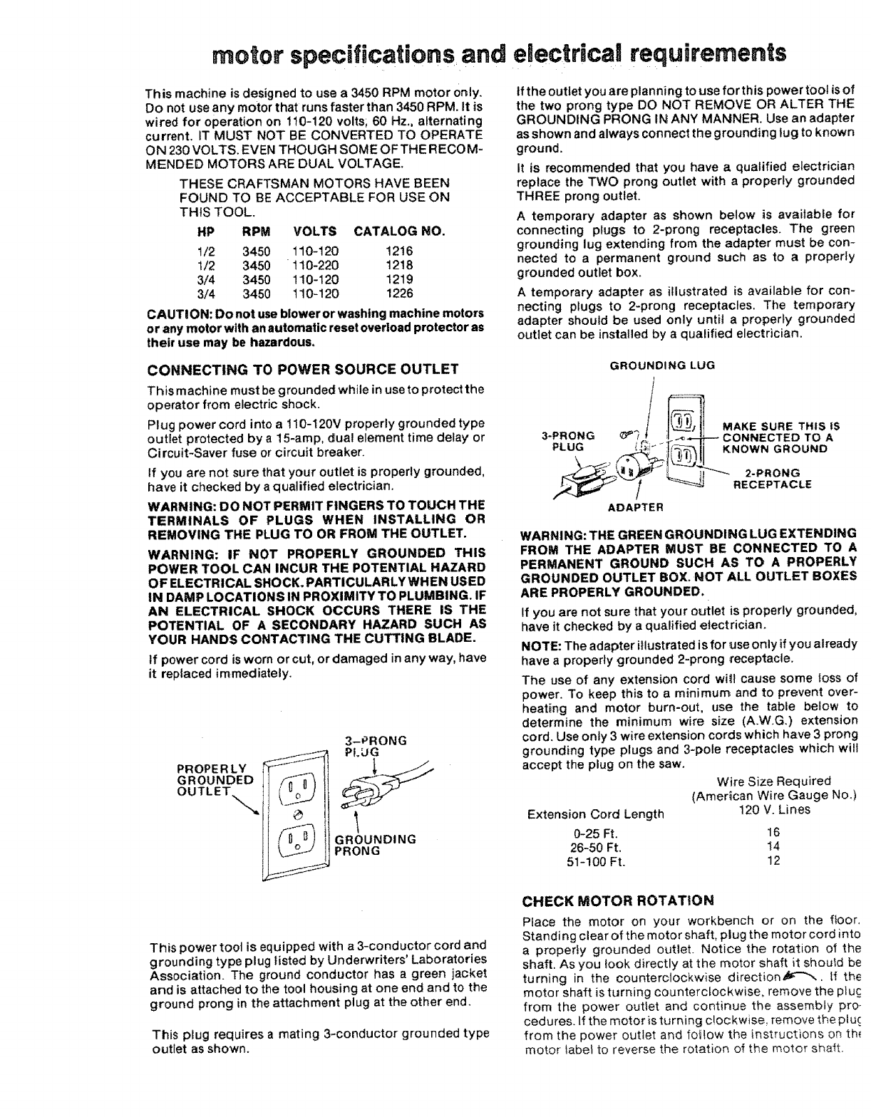
ifthe outlet you are planning to use for this power tool is of
the two prong type DO NOT REMOVE OR ALTER THE
GROUNDING PRONG IN ANY MANNER. Use an adapter
as shown and always connect the grounding lug to known
ground.
It is recommended that you have a qualified electrician
replace the TWO prong outlet with a properly grounded
THREE prong outlet.
A temporary adapter as shown below is available for
connecting plugs to 2-prong receptacles. The green
grounding lug extending from the adapter must be con-
nected to a permanent ground such as to a properly
grounded outlet box.
Atemporary adapter as illustrated is available for con-
necting plugs to 2-prong receptacles. The temporary
adapter should be used only until a properly grounded
outlet can be installed by aqualified electrician.
GROUNDING LUG
_' "_,,_,_.,,,.._' LIJ 2-PRONG
/_RECEPTACLE
ADAPTER
WARNING: THE GREEN GROUNDING LUG EXTENDING
FROM THE ADAPTER MUST BE CONNECTED TO A
PERMANENT GROUND SUCH AS TO A PROPERLY
GROUNDED OUTLET BOX. NOT ALL OUTLET BOXES
ARE PROPERLY GROUNDED.
If you are not sure that your outlet is properly grounded,
have it checked by aqualified electrician.
NOTE: The adapter illustrated is for tJseonly if you already
have a properly grounded 2-prong _eceptacle.
The use of any extension cord wilt cause some loss of
power. To keep this to a minimum and to prevent over-
heating and motor burn-out, use the table below to
determine the minimum wire size (A.WG.) extension
cord. Use only 3 wire extension cords which have 3 prong
grounding type plugs and 3-pole receptacles which will
accept the plug on the saw.
Wire Size Required
(American Wire Gauge No.)
120 V. Lines
Extension Cord Length
0-25 Ft. 16
26-50 Ft. 14
51-100 Ft. 12
This power toot is equipped with a 3-conductor cord and
grounding type plug listed by Underwriters' Laboratories
Association. The ground conductor has a green jacket
and is attached to the tool housing at one end and to the
ground prong in the attachment plug at the other end.
This plug requires a mating 3-conductor grounded type
outlet as shown.
CHECK MOTOR ROTATION
Place the motor on your workbench or on the floor.
Standing clear of the motor shaft, plug the motor cord into
a properiy grounded outlet. Notice the rotation of the
shaft. As you took directly at the motor shaft it shoufd be
turning in the counterclockwise direction,_J_"_--, tf the
motor shaft is turning counterclockwise, remove the ptuc
from the power outlet and continue the assembly pro-
cedures. If the motor isturning clockwise, remove the pluc.
from the power outlet and foi!ow the instructions on th{
motor labet to reverse the rotation of the motor shaft.
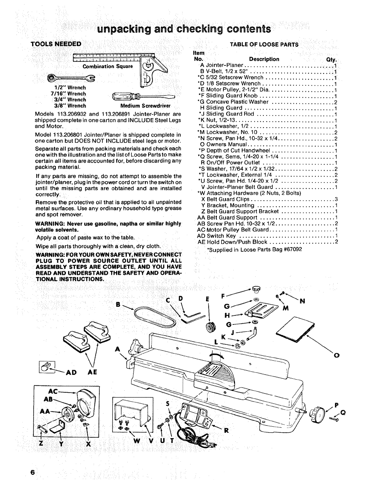
unpaCkingand checking contents :
.... , TA.LEO LOOSEPARTS
No. :, Description .... Qty.:
i: :: : Combination Square A Jointer-Ptaner ............... ...........
.... B V-Belt, 1/2 x 52" .. ........................ ; _l
i / i•i ii i
1/2" Wrench : ::
7116_ Wrench
:lWrench
3i8' Wrench Medium Screwdriver
Models t13.206932 and 113.20689t Jointer-Planer are
shipped complete in one carton and INCLU DE Steel Legs
and Motor.
Model 113.206801 Jointer/Planer is shipped complete in
one carton but DOES NOT INCLUDE steel legs or motor.
Separate all parts from packing materials and check each
one with the illustration and the list of Loose Parts to make
certain all items are accounted for, before discarding any
packing material.
If any parts are missing, do not attempt to assemble the
jointer/planer, plug in the power cord or turn the switch on
until the missing parts are obtained and are installed
correctly.i. .....
Remove the protective oil that is applied to atl unpainted
metal surfaces. Use any ordinary household type grease
and spot remover.
WARNING: Never use gasoline, naptha or similar highly
volatile solvents.
Apply a Coat of paste wax to the table.... :
Wipe all parts thoroughly with aclean, dry cloth.
WARNING.': FOR YOUR OWN SAFETY ;:NEVER CONNECT
PLUG TO POWER SOURCE OUTLET UNTIL ALL
ASSEMBLY STEPS ARE COMPLETE, AI_D YOU HAVE
READ AND UNDERSTAND THE SAFETY AND OPERA-
*C 5/32 Setscrew Wrench ....................... i
*D 1/8 Setscrew Wrench ........................ 1
*E Motor Pulley, 2-1/2" Dia ...................... 1
*F Sliding Guard Knob ......................... 1
*G Concave Plastic Washer ..................... 2
H Sliding Guard .............................. 1
*J Sliding Guard Rod .......................... 1
*K Nut, 1/2-13 ................................. 1
*L Lockwasher, 1/2 ............................ 1
*M Lockwasher, No. 10 ......................... 2
*N Screw, Pan Hd., 10-32 x 1/4 ................... 2
O Owners Manual ............................. 1
*P Depth of Cut Handwheel ..................... 1
*Q Screw, Sems, 1/4-20 x 1-1/4 .................. 1
R On/Off Power Outlet ........................ 1
*S Washer, 17/64 x 1/2 x 1/32 .................... 2
*T Lockwasher, External 1/4 .................... 2
*U Screw, Pan Hd. 1/4-20 x 1/2 .................. 2
V Jointer-Planer Belt Guard .................... 1
*W Attaching Hardware (2 Nuts, 2 Bolts)
X Belt Guard Clips ............................ 3
Y Bracket, Mounting .......................... 1
ZBelt Guard Support Bracket .................. 1
AA Belt Guard Support ......................... 1
AB Screw Pan Hd. 10-32 x 1/2 .................... 2
ACMotor Pulley Belt Guard ...................... 1
AD Switch Key ................................ 1
AE Hold Down!Push Block ...................... 2
"Supplied in Loose Parts Bag #67092
i
!
61: • ..... :
• • ; :i ¸ i;¸ i ¸ ; : • •
unpacking and checking contents
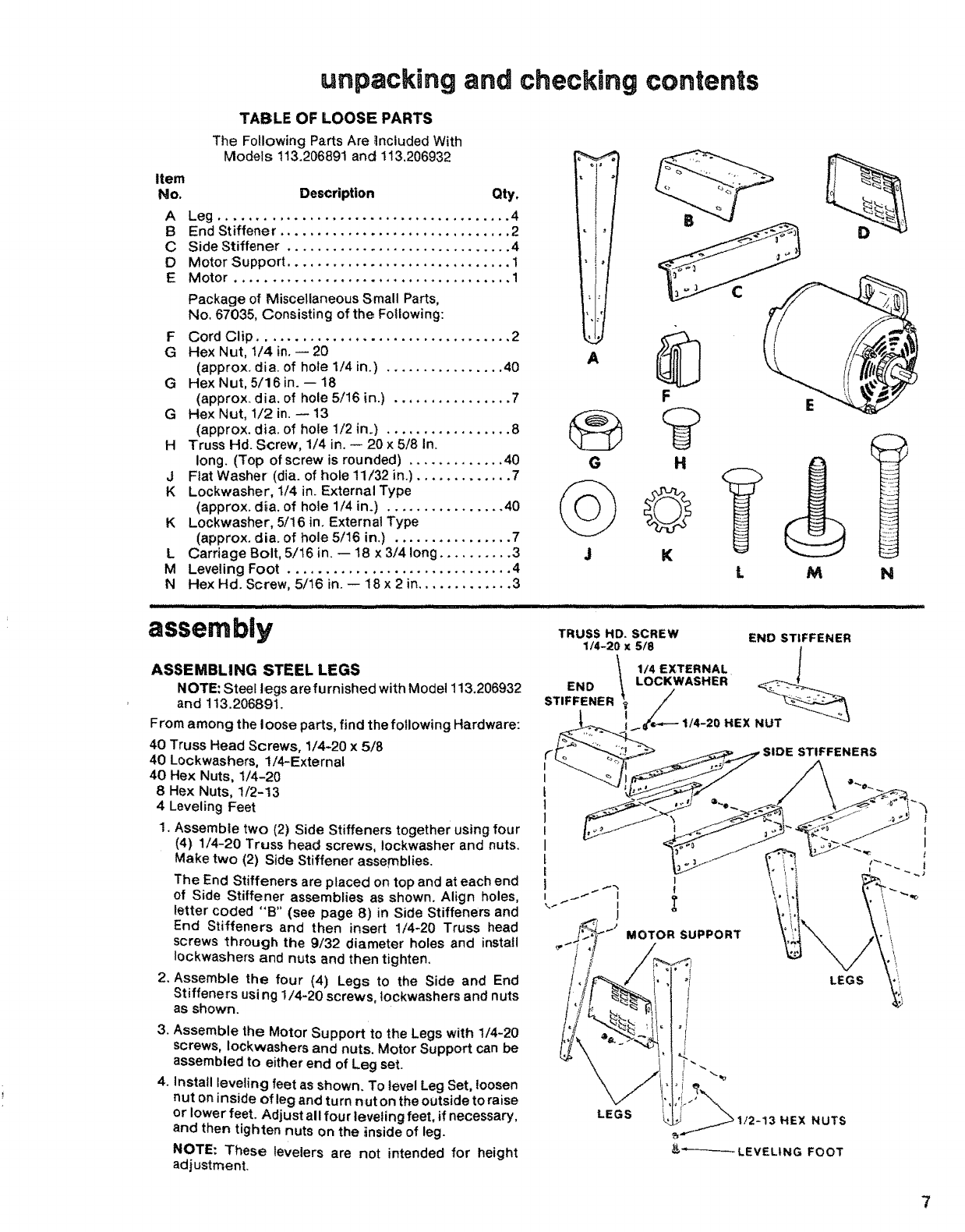
TABLE OF LOOSE PARTS
The Following Parts Are Included With
Models 113.206891 and 113,206932
Item
No. Description Qty.
ALeg ....................................... 4
BEnd Stiffener ............................... 2
C Side Stiffener .............................. 4
D Motor Support .............................. 1
E Motor ..................................... 1
Package of Miscellaneous Small Parts,
No, 67035, Consisting of the Following:
FCord Clip .................................. 2
G Hex Nut, 1/4 in. -- 20
(approx. dia. of hole 1/4 in.) ................ 40
G HexNut, 5/16in.-- 18
(approx. dia. of hole 5116 in.) ................ 7
G Hex Nut, 1/2 in. -- 13
(approx. dia. of hole 1/2 in.) ................. 8
H Truss Hd. Screw, 1/4 in. -- 20 x 5/8 In.
long. (Top of screw is rounded) ............. 40
J Flat Washer (dia. of hole 11/32 in.) ............. 7
K Lockwasher, 1/4 in. External Type
(approx. dia. of hole 1/4 in.) ................ 40
K Lockwasher, 5/16 in+ External Type
(approx. dia. of hole 5/16 in.) ................ 7
LCarriage Bolt, 5/16 in. -- 18 x 3/4 long .......... 3
M Leveling Foot .............................. 4
N Hex Hd. Screw, 5/16 in. -- 18x 2 in............. 3
G
assembly
H
©
K
ASSEMBLING STEEL LEGS
NOTE: Steel legs are furnished with Model 113,206932
and 113.20689t.
From among the loose parts, find the following Hardware:
40 Truss Head Screws, 1/4-20 x 518
40 Lockwashers, !!4-External
40 Hex Nuts, 114-20
8 Hex Nuts, t/2-13
4 Leveling Feet
1. Assemble two (2) Side Stiffeners together using four
(4) 1/4-20 Truss head screws, Iockwasher and nuts.
Make two (2) Side Stiffener assemblies.
The End Stiffeners are placed on top and at each end
of Side Stiffener assemblies as shown. Align holes,
letter coded "B" (see page 8) in Side Stiffeners and
End Stiffeners and then insert 1/4-20 Truss head
screws through the 9/32 diameter holes and install
Iockwashers and nuts and then tighten.
2. Assemble the four (4) Legs to the Side and End
Stiffeners us/ng 1/4-20 screws, lockwashers and nuts
as shown.
3. Assemble the Motor Support to the Legs with 1/4-20
screws, Iockwashers and nuts. Motor Support can be
assembled to either end of Leg set.
4. Install leveling feet as shown. To level Leg Set, loosen
nut oninside of leg and turn nut on the outside to raise
or lower feet. Adjust all four leveling feet, if necessary,
and then tighten nuts on the inside of leg.
NOTE: These levelers are not intended for height
adjustment.
TRUSS HD. SCREW
1/4-20 x 5/8
L M N
END ST|FFENER
7
assembly
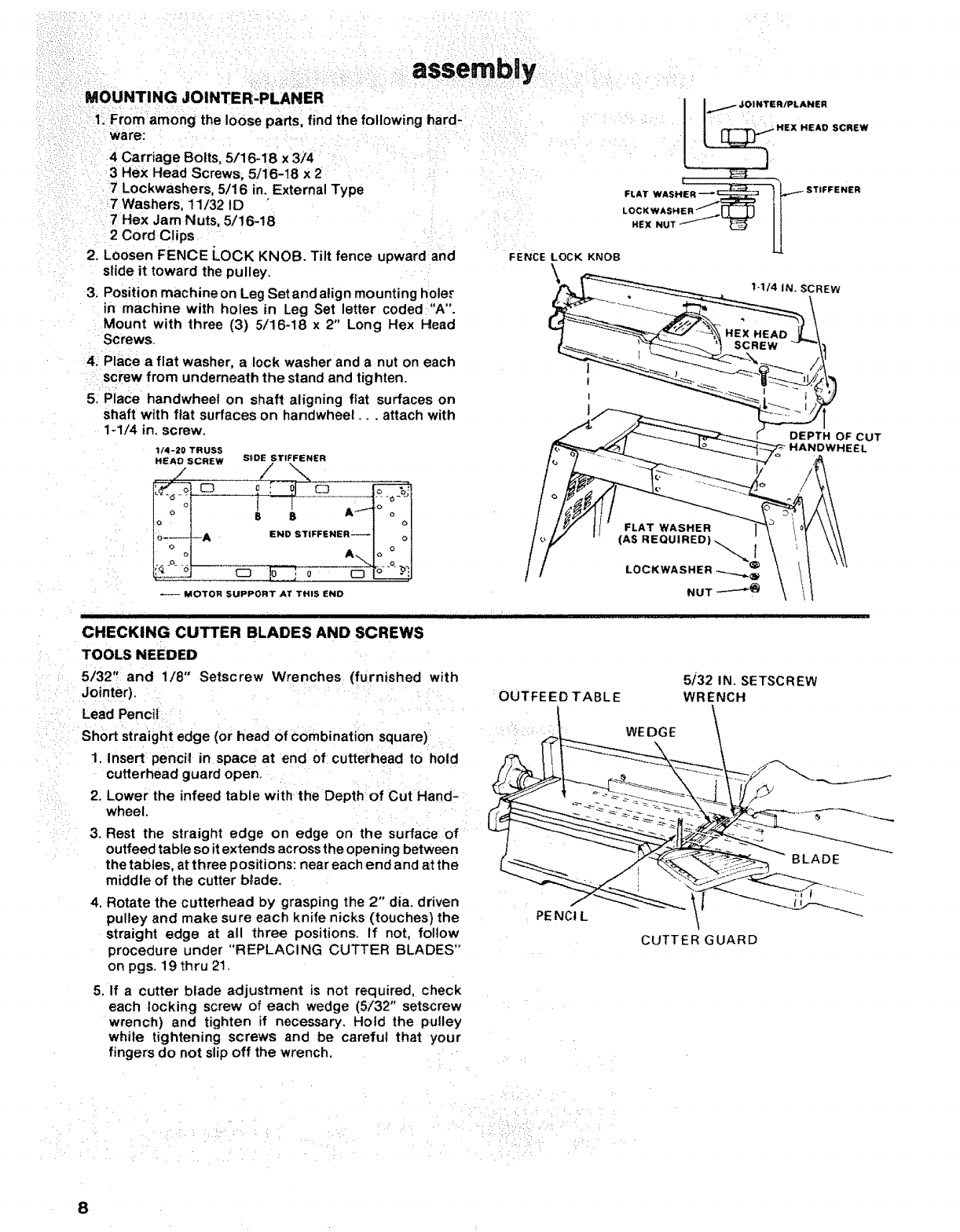
MOUNTING JOINTER-PLANER
i:. From among the loose parts, find the following hard-
ware:
4 Carriage Bolts, 5/16-18 x 3/4
3 Hex Head Screws; 5/16-18 x 2
7 Lockwashers, 5/16 in. External Type
7Washers, 11/32 ID
7 Hex Jam Nuts, 5/16-18
2 Cord Clips
2. Loosen FENCE LOCK KNOB. Tilt fence upward and
slide it toward the pulley.
3; Position machine on Leg Setand align mounting hole._
in machine with holes in Leg Set letter coded "A".
Mount with three (3) 5/16-18 x 2" Long Hex Head
Screws.
4. Place a flat washer, a lock washer and a nut on each
screw from underneath the stand and tighten.
5: Place handwheef on shaft aligning ftat surfaces on
shaft with flat surfaces on handwheel.., attach with
1-1/4 in. screw.
1f4-20 TRUSS
HEAD SCREW S_DE STIFFENER
//\
A EN TIFFENE
-- MOTOR SUPPORT AT THIS END
FLAT WASHER
l
DEPTH OF CUT
HANDWHEEL
IIL_ J JJJJl I I i
CHECKING CUTTER BLADES AND SCREWS
TOOLS NEEDED
: 5i32" and 118" Setscrew Wrenches (furnished with 5/32 IN. SETSCREW
OUTFEED TABLE WRENCHiJ°inter).
Lead Pencii /
Short straight edge (or head of Combination square)i :i ____....._ WEDGE
i1, Insert penci;! in space at end of cutterhead to hold ,L"k. I! ! __
cutterhead guard open. _ _______ _--
2. Lower the infeed table wilth the Depth of Cut Hand-
wheel %
3. Rest the straight edge on edge on the surface of
outfeed table so itextends across the open ing between -_'-_ _
the tables, at three positions: neareach endand atthe _ .__
middle of the cutter b_ade. ""--..,.__ _Y_-_
4. Rotate the cutterhead by grasping the 2" die. driven __
pulley and make sure each knife nicks (touches) the PENCt L
straight edge at all three positions. If not, follow CUTTER GUARD
procedure under "REPLACING CUTTER BLADES"
on pgs. 19 thru 21.
5. If a cutter blade adjustment is not required, check
each locking screw of each wedge (5/32" setscrew
wrench) and tighten if necessary. Hold the pulley
while tightening screws and be careful that your
fingers do not slip off the wrench,
..... /
i •_ :::: :i, :,i:,i _ ,, • _ ,:
::,: i, _ : ,:
8
MOUNTING SW|TCH
1. Locate the following parts:
!On/Off Power Outlet
2Pan Hd. Screws, 1/4-20 x 1/2
IIj!' ILLLjl II JI!l II I
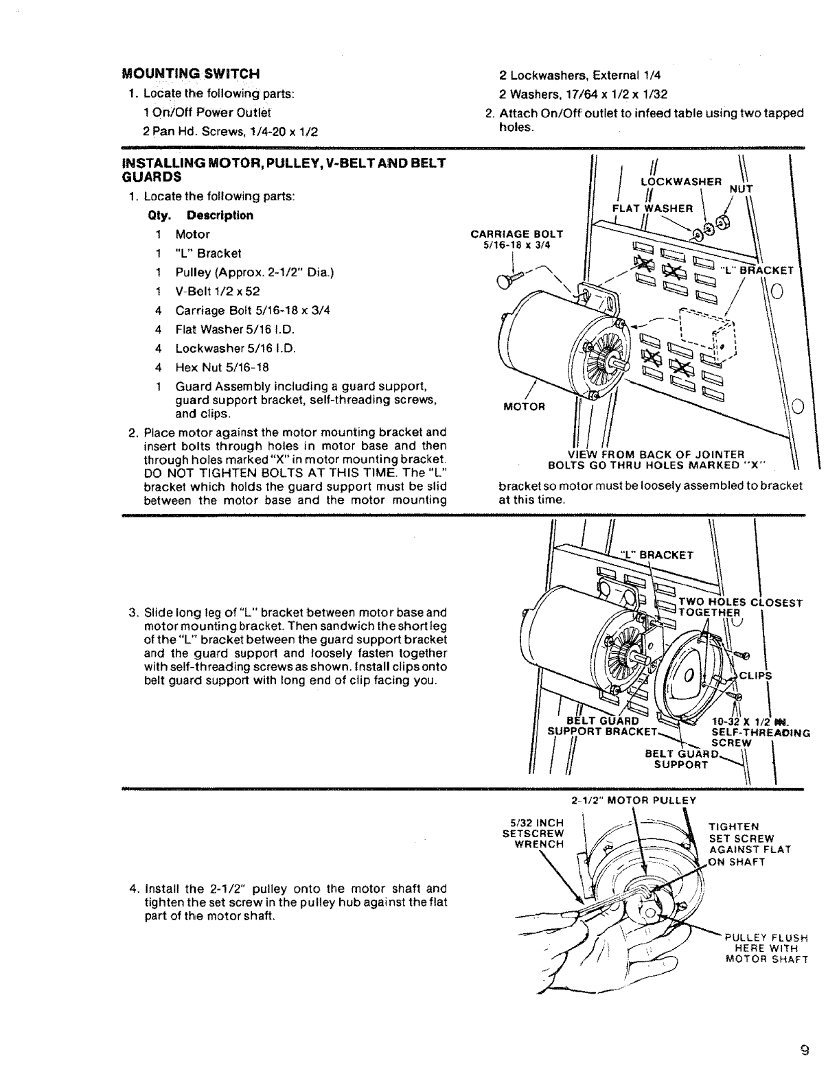
INSTALLING MOTOR, PULLEY, V-BELT AND BELT
GUARDS
1. Locate the following parts:
Qty. Description
1 Motor
1"L" Bracket
2Lockwashers, External 1/4
2 Washers, 17/64 x 1/2 x1/32
2. Attach On/Off outlet to infeed table using two tapped
holes.
! Pulley (Approx. 2-1/2" Dia.)
1 V-Belt 1/2x52
CARRIAGE BOLT
5/16-18 x 3/4
4Carriage Bolt 5/16-18 x 3/4
4Flat Washer5/16 I.D.
4 Lockwasher 5/16 I.D.
4 Hex Nut 5/16-18
1Guard Assembly including a guard support,
guard support bracket, self-threading screws,
and clips,
2, Place motor against the motor mounting bracket and
insert bolts through holes in motor base and then
through holes marked "X" in motor mounting bracket.
DO NOT TIGHTEN BOLTS AT THIS TIME. The "L"
bracket which holds the guard support must be slid
between the motor base and the motor mounting
3. Slide long teg of"L" bracket between motor base and
motor mounting brackeL Then sandwich the short leg
of the"L" bracket between the guard support bracket
and the guard support and loosely fasten together
with self-threading screws as shown. _nstall clips onto
belt guard support with long end of clip facing you.
bracket so motor must be loosely assembled to bracket
at this time.
SUPPORT BRA(
///
BRACKET
TWO HOLES CLOSEST
TOGETHER
_CLIPS
t0-32 X112 IN.
SELF-THREADING
SCREW
BELT GUARD_,_ I_
SUPPORT _'_t
2-1/2" MOTOR PULLEY
5/32 INCH
SETSCREW
WRENCH
TIGHTEN
SET SCREW
AGAINST FLAT
ON SHAFT
4. Install the 2-1/2" pulley onto the motor shaft and
tighten the set screw in the pulley hub against the flat
part of the motor shaft.
FLUSH
HERE WtTH
MOTOR SHAFT
9
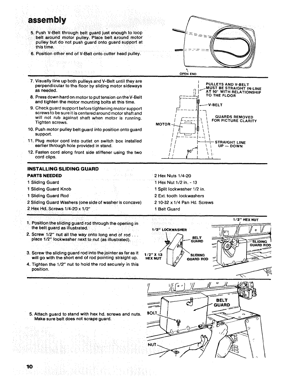
6. P0sition btherend Of V:Belt ontoCutter head p_iiey. ........ :
i:
ii1111111 i i ]i i i ii iiii iiii
eupbothpueys dan until they areV-Belt
7. Visually fin tl
perpendicular to the floor by sliding motor sideways
as needed.
8. Press down hard on motor to put tension on theV-Belt
and tighten the motor mounting bolts at this time.
9. Check guard support before tightening motor support
screws to be sure it is centered around motor shaft and
will not rub against shaft when motor is running.
Tighten screws.
10. Push motor pulley belt guard into position onto guard
support.
11. Plug motor cord into outlet on switch box installed
eadier through hole provided in stand.
12, Fasten cord along front side stiffener using the two
cord clips.
'" " I' ' '' ............ ;............ ..............
INSTALLING SLIDING GUARD :
PARTS NEEDED
i.... ::" ....
Sliding Guard
1 Sliding Guard Knob
1 Sliding Guard Rod
OPEN END
II iiiii .lUll II II IH
PULLEYS AND V-BELT
..I-MUST BE STRAIGHT IN-LINE
__ AT 90°WITH RELATIONSHIP
_-_--__. TO THE FLOOR
1,----_V-BELT
[ ........ ! GUARDS REMOVED
/_=___:__.... _ _ FOR PICTURE CLARITY
MOTOR _i_-_r \
//i:'_--_ STRAIGHT LINE
/ / .J _, I UP--DOWN
/ / 9o_'m, \ I
// (I ',',
:2Hex Nuts 1/4-20
......... '1 Rex Nut 1/2 in. - 13
1 Split iockwasher 1/2 in,
2 Ext, tooth Iockwashers
2Sliding Guard Washers(one side of washer is concave)
.2HeX Hd; Screws 1/4-2Ox !/2"
2: Screw i/2" nut all the way onto long end0f rod..:.
place i/2!' !ockwasher next to nut (as illustrated) ....
3. SCrew the sliding guard rod into the jointer as far as it
wil! go with the short end of rod pointing straight up.
4. Tighten the i/2" nutto hold the rod securely in this
position.
2 10-32 x1/4 Pan Hd. Screws
I Belt Guard
....... Ill I J IJ
1:::Positionihe sli;ding guaid !:r0d throughthe opening in
the belt guard asillUstratedl :;...... 1i2, LOCKWAS_R
!:: BELT
__ GUARD
/
1/2" X 13 /o/ SLIDING
HEX NUT )_/ GUARD ROD
y
iiii i iiiii i ii iiiJlll
1/2" HEX NUT
GUARD RO0
5. Attach guard to stand with hex hd. screws and nuts.
Make sure belt does not scrape guard.
BELT
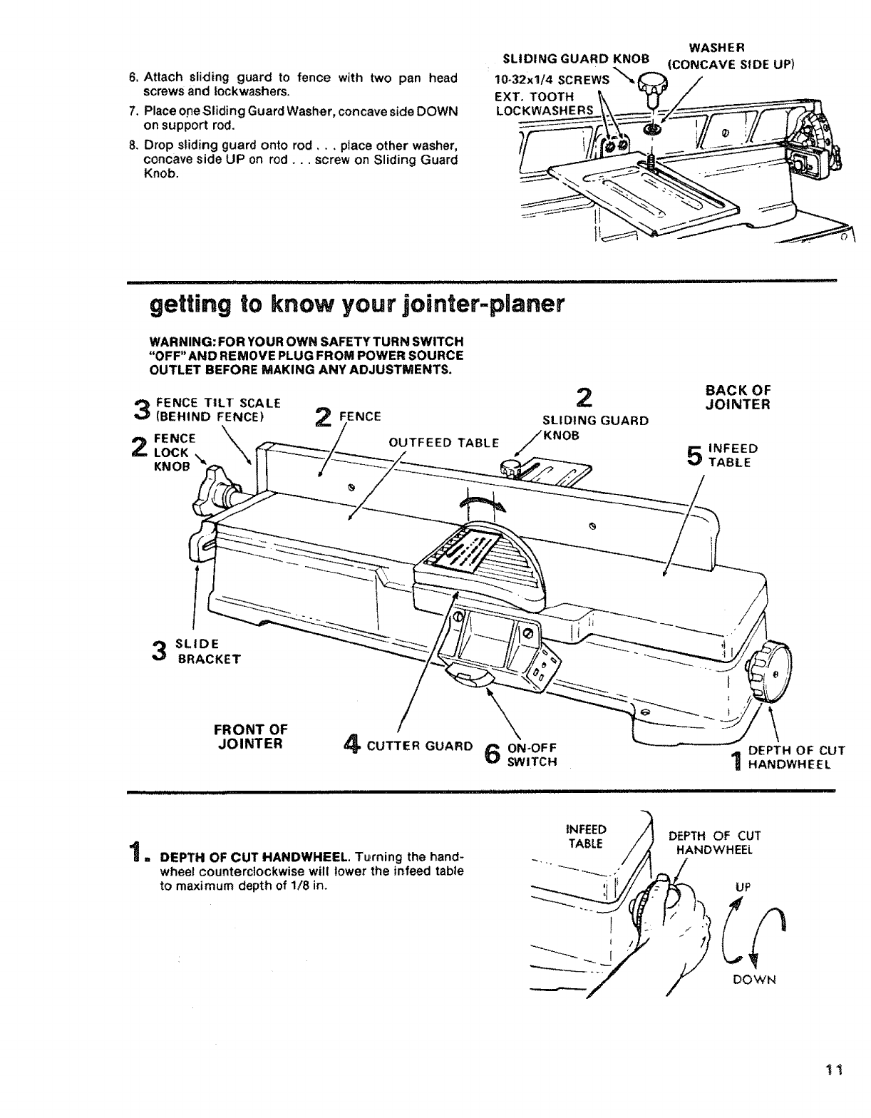
6.Attachslidingguardto fence with two pan head
screws and lockwashers,
7. Place one Sliding Guard Washer, concave side DOWN
on support rod.
8. Drop sliding guard onto rod,., place other washer,
concave side UP on rod.., screw on Sliding Guard
Knob.
SLIDING GUARD KNOB
:10-32xl/4 SCREWS'_
EXT. TOOTH
LOCKWASHERS
WASH ER
(CONCAVE SIDE UP)
getting to know your jointer-planer
WARNING: FOR YOUR OWN SAFETY TURN SWITCH
"OFF"AND REMOVE PLUG FROM POWER SOURCE
OUTLET BEFORE MAKING ANY ADJUSTMENTS.
FENCE TILT SCALE
(BEHIND FENCE)
2 FENCE \,
LOCK
KNOB
FENCE
OUTFEED TABLE
2
SLIDING GUARD
KNOB
BACK OF
JOINTER
5INFEED
TABLE
Ii
SLtDE
BRACKET
F.O.TOF /\
JOINTER 4CUTTER GUARD 6 ON-OFF DEPTH OF CUT
SWITCH 1HANDWHEEL
DEPTH OF CUT HANDWHEEL. Tu_rning the hand-
wheel counterclockwise will lower the infeed table
to maximum depth of 1/8 in.
i_N%p /i D_PTHOFCUT
.... /At_LI_ /_HANDWHEEL
___,.___/ /DOWN
..... ..... your joi ............: gettmg to know :nter-pianer
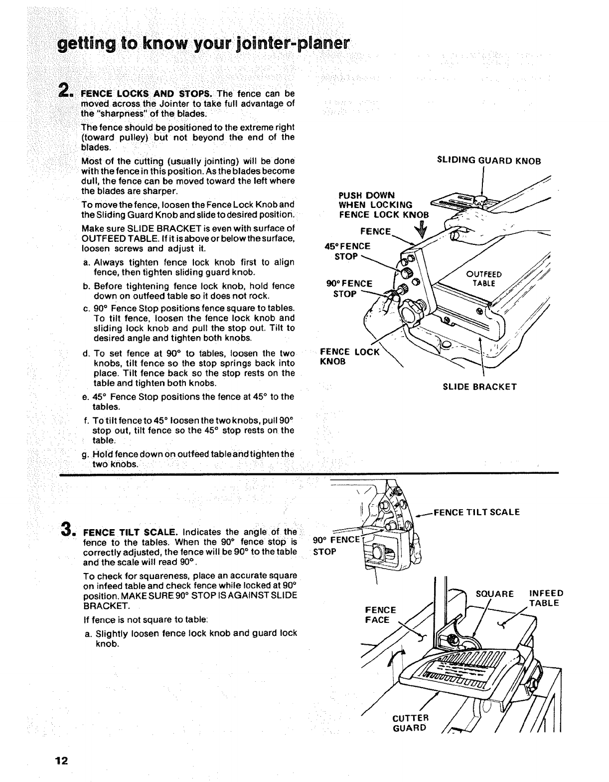
g--re:FENCE LOCKS AND STOPS. _The fence can be
moved across the J:ointer to take full advantage of
the "sharpness" of the blades.
The fence should be positioned to the extreme right
(toward pulley) but not beyond the end of the
blades.
Most of the cutting (usually jointing) will be done
with the fence in this position. As the blades become
dull, the fence can be moved toward the left where
the blades are sharper.
To move the fence, loosen the Fence Lock Knob and
the Sliding Guard Knob and slide to desi red position.
Make sure SLIDE BRACKET is even with surface of
OUTFEED TABLE. tf it is above or below the surface,
loosen screws and adjust it.
a. Always tighten fence lock knob first to align
fence, then tighten sliding guard knob.
b. Before tightening fence lock knob, hold fence
down on outfeed table so it does not rock.
C. 90° Fence Stop positions fence square to tables.
To tilt fence, loosen the fence lock knob and
sliding lock knob and pull the stop out, Tilt to
desired angle and tighten both knobs.
•d.
': e,
To set fence at 90 °to tables, loosen the two
knobs, tilt fence so the stop springs back into
place. Tilt fence back so the stop rests on the
table and tighten both knobs.
45° Fence Stop positions the fence at 45 ° to the
tables.
SL,D,.GGUARDKNOB
PUSH DOWN _-_ __
WHENLOCKING
/"OUTFEED
KNOB %_
: SLIDE BRACKET
: f. To tilt fence to 45 ° loosen the two knobs, pull 900
:.... stop out, tilt fence so the 45 °stop rests on the ....
' ...... table.
....:.... g. Hold fence down on outfeed table and tighten the
::: : =: two knobs. :
: : FENCE TILT SCALE Indicatesl the an:le oi the:: _il -"
fence to the tables. _/Vhen the 90° fenge stop is _: 9o °FENCE _ _Q
correctly adjusted, the fence will be 90 ° to the table STOP t_ _1_ [
and the scale will read 90° , _
To check for squareness, place an accurate square
on infeed table and check fence while locked at 90°
position. MAKE SURE 90 °STOP IS AGAINST SLIDE
BRACKET.
tf fence is not square to table:
a. Slightly loosen fence lock knob and guard lock
knob.
__.-- FENCE TI LT SCALE
INFEED
TABLE
12
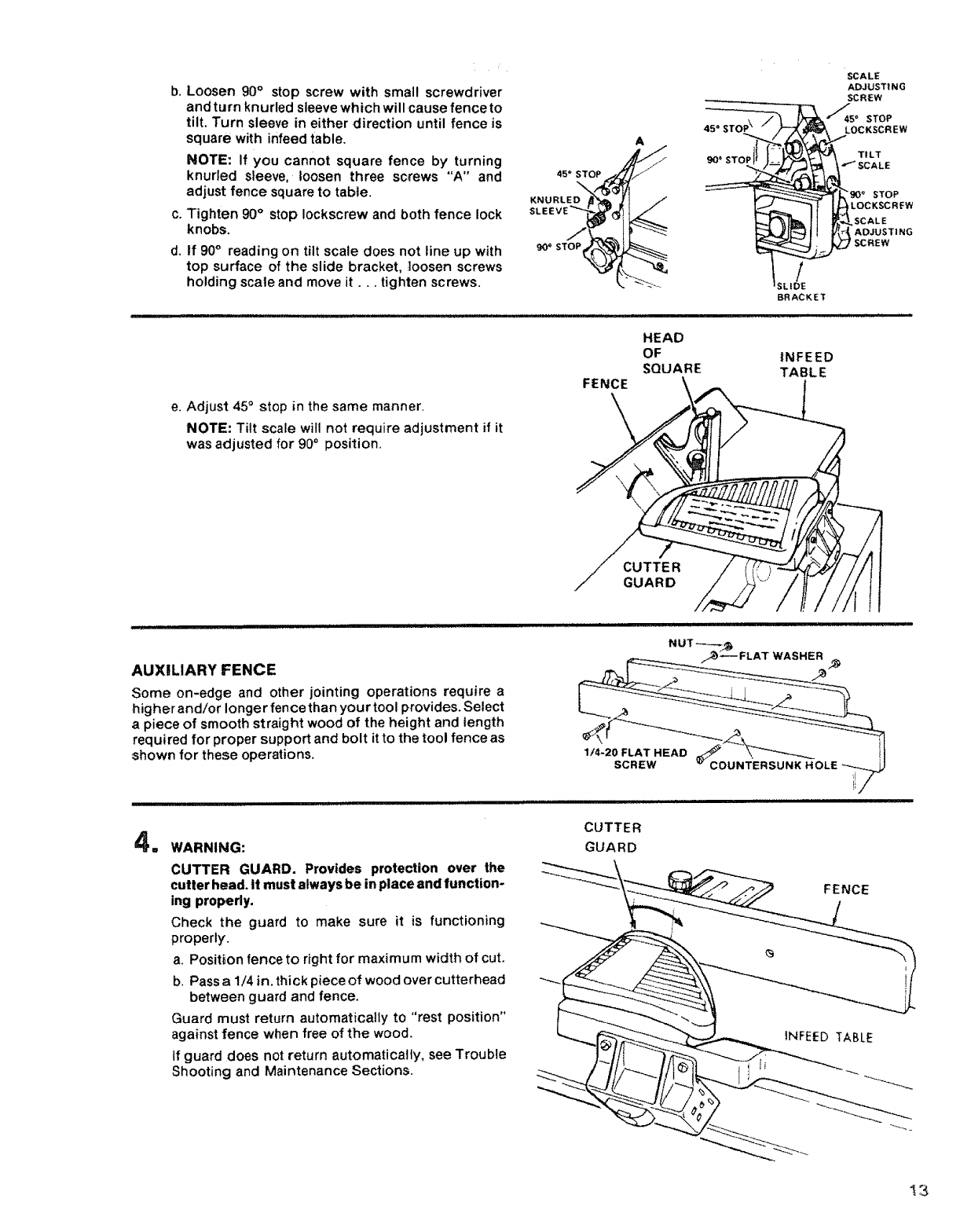
b.
Co
d.
Loosen 90° stop screw with small screwdriver
and turn knurled sleeve which will cause fence to
tilt. Turn sleeve in either ,direction until fence is
square with infeed table,
NOTE: If you cannot square fence by turning
knurled sleeve, loosen three screws "A" and
adjust fence square to table.
Tighten 90°stop Iockscrew and both fence lock
knobs,
tf 90° reading on tilt scale does not line up with
top surface of the slide bracket, _ioosen screws
holding scale and move it... tighten screws.
45" STOP \
_J0_ STOP
/
SLIDE
BRACKET
SCALE
ADJUSTING
SCREW
'_45 _STOP
LOCKSCREW
TILT
,,ISCALE
"gO ° STOP
LOCKSCRFW
SCALE
ADJUST! NG
SCREW
e. Adjust 45°stop in the same manner.
NOTE: Titt scale will not require adjustment if it
was adjusted for 90° position,
FENCE
HEAD
OF
SQUARE
\
CUTTER
GUARD
|NFEED
TABLE
] , ,,,, ,,,,,, i i !ll
AUXILIARY FENCE
Some on-edge and other jointing operations require a
higher and/or longer fence than your tool provides. Select
apiece of smooth straight wood of the height and length
required for proper support and bolt itto the tool fence as
shown for these operations. 1/4-20 FLAT HEAD J
SCREW _COUNTERSL
at WARNING:
CUTTER GUARD. Provides protection over the
cutter head. It must always be in place and function-
ing properly.
Check the guard to make sure it is functioning
properly.
a. Posit_on fence to right for maximum width of cut.
b. Pass a 1/4 in. thick piece of wood over cutterhead
between guard and fence.
Guard must return automatically to "rest position"
against fence when free of the wood,
If guard does not return automatically, see Trouble
Shooting and Maintenance Sections.
CUTTER
GUARD
FENCE
13
:to : yourjo" te lane
getting:: know:: mn r,p r
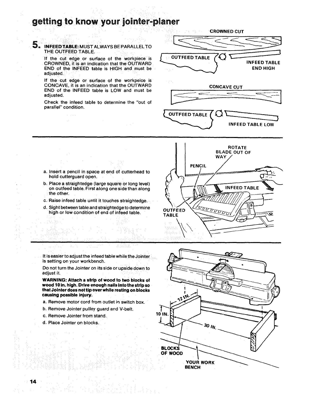
iCROWNED CUT
5; _,.,EEO_=E"MUST,LWAYSBEPARALLEL.TO
THE OUTFEED TABLE. .....
If the :cUt edge or surface of the workpiece is
CROWNED, it isan indication that the OUTWARD
END of the INFEED table is HIGH and must be
adjusted. :
tf the cut edge or surface of the workpeice is
CONCAVE, it is an indication that the OUTWARD
END of the INFEED table is LOW and must be
adjusted.
Check the infeed table to determine the "out of
parallel" condition.
i:I_,I_<_--_-__ '> _L_ __--_--'-I
: END HIGH
CONCAVE CUT
INFEED TABLE LOW
a. Insert a pencil in space at end of cutterhead to
hold cutterguard open,
b. Place a straightedge (large square or long level)
on outfeed table, First along oneside than along
the other,
c,,Raise infeed table until it touches straightedge,
d, Sight between table and straightedge to determine
high or tow condition of end of infeed table.
PENCIL
"
OUTFEED
TABLE
,111 iiiii ,,,,i, iiii :111 i iiiiiiiiiiiiiii
ROTATE
BLADE OUT OF
WAY
It is easier to adjust the infeed table whi ethe Jointe r:
is setting on your workbench.
Do not turn the Jointer on its side or upside down to
adjust it, : :: :
WARNING: Attach a strip of wood to two blocks of
wood 10 in. high. Drive enough nails into the strip so
that Jointer does not tip over while resting on blocks
causing possible injury.
a, Remove motor cord from outlet in switch box.
b. Remove Jointer pulley guard and V-belt.
c. Remove Jointer from stand. 10 IN.
!
d, Place Jointer on blocks.
• H :¸¸•:• :• !: :;: • •_
14
BLOCKS
OF WOOD
YOUR WORK
BENCH
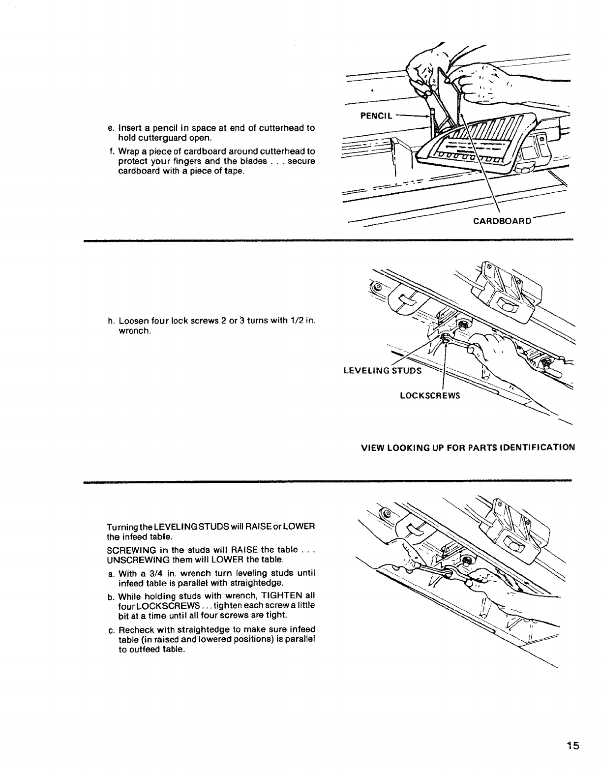
e. Insert a pencil in space at end of cutterhead to
hold cutterguard open.
f. Wrap a piece of cardboard around cutterhead to
protect your fingers and the blades.., secure
cardboard with apiece of tape.
PENCI L
h. Loosen four lock screws 2 or'3 turns with 1/2 in.
wrench.
VIEW LOOKING UP FOR PARTS IDENTIFICATION
Turning the LEVELING STUDS will RAISE or LOWER
the infeed table.
SCREWING in the studs will RAISE the table...
UNSCREWING them will LOWER the table.
a. With a3/4 in. wrench turn levering studs until
infeed table is parallel with straightedge.
b. While holding studs with wrench, TIGHTEN all
four LOCKSCREWS. ,. tighten each screw a little
bit at a time until all four screws are tight.
c. Recheck with straightedge to make sure infeed
table (in raised and lowered positions) is parallel
to outfeed table.
15
getting m • "
to,know your jomter-planer
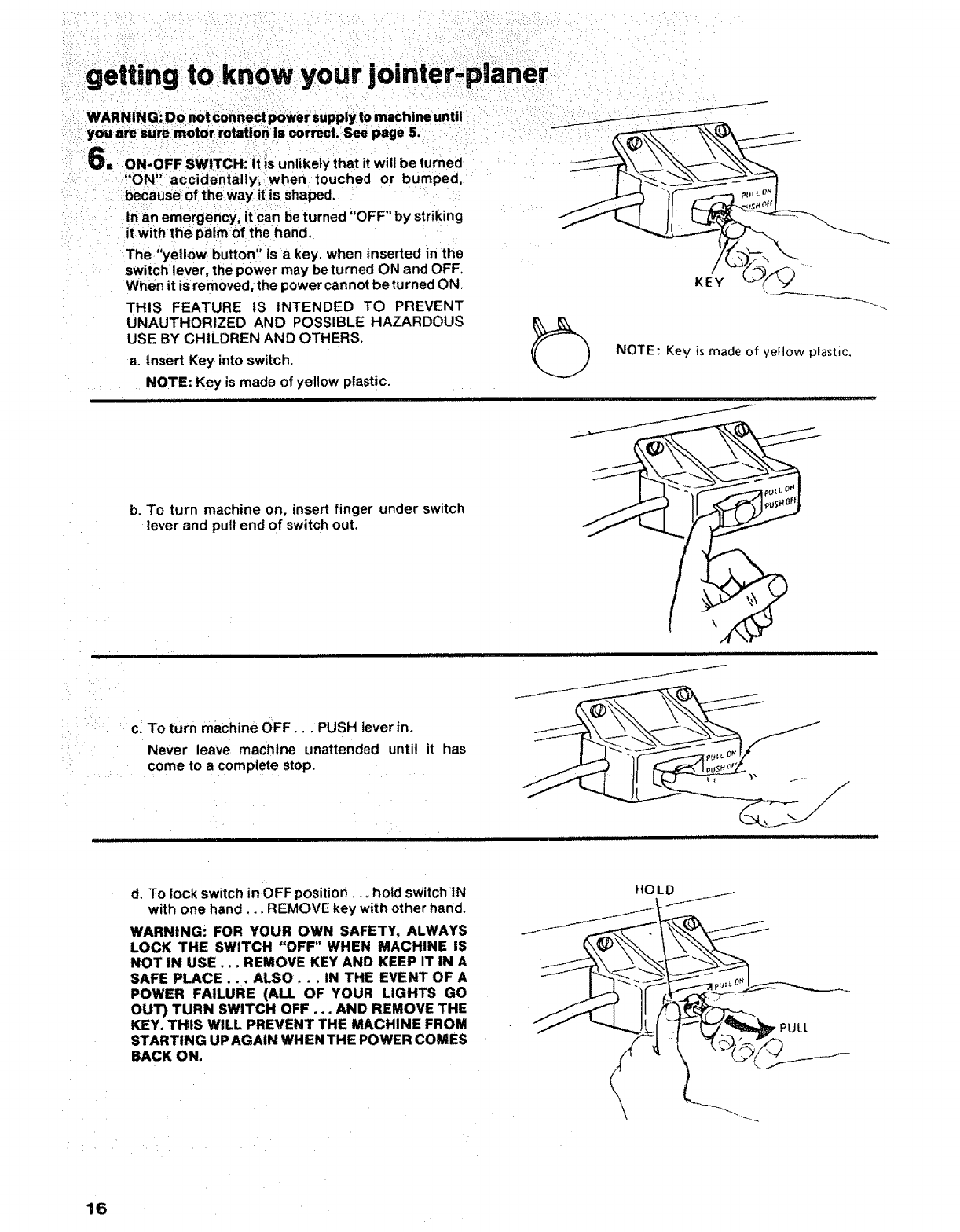
I_'_': ON-OFF SWITCH: it is unlikely that it will be turned
"ON" accidentally, when touched or bumped,
because of the way it is shaped.
Inan emergency, it can be turned "OFF" by striking
it with the palm of the hand.
The "yellow button" is a key, when inserted in the
switch lever, the power may be turned ON and OFF
When it is removed; the power cannot be turned ON.
THIS FEATURE IS INTENDED TO PREVENT
UNAUTHORIZED AND POSSIBLE HAZARDOUS
USE BY CHILDREN AND OTHERS.
aInsert Key into switch.
NOTE: Key is made of yellow plastic.
............... i ] i ii|ll
/
KEY
NOTE: Key is made of yellow plastic.
b. To turn machine on, insert finger under switch
lever and pull end of switch out.
l II IIIIII II I l lHll I I IIIIIIIIIIII[IUIJIIU
c+TO turn machine OFF... PUSH lever in.
Never leaVe machine unattended until it has
: : come to a complete stop.
JLLIU_IjtJ III I I 'III i ii ii
ii,
J
J
i ii ii iiii i i lUlUll.
d. To lock switch inOFF position .... hold switch 1N
with one hand... REMOVE key with other hand.
WARNING: FOR YOUR OWN SAFETY, ALWAYS
LOCK THE SWITCH "OFF" WHEN MACHINE iS
NOT IN USE... REMOVE KEY AND KEEP IT IN A
SAFE PLACE... ALSO... IN THE EVENT OF A
POWER FAILURE (ALL OF YOUR LIGHTS GO
OUT) TURN SWITCH OFF .+. AND REMOVE THE
KEY. THIS WILL PREVENT THE MACHINE FROM
STARTING UP AGAIN WHEN THE POWER COMES
BACK ON.
HOLD
\
PULL
16
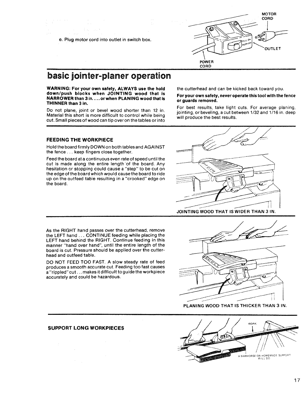
e. P!ug motor cord into outlet in switch box.
MOTOR
CORD
f
OUTLET
POWER
CORD
basic jointer-pUaner operation
WARNING: For your own safety, ALWAYS use the hold
down!push blocks when JOINTING wood that is
NARROWER than 3 in.... or when PLANING wood that is
THINNER than 3 in.
Do not plane, joint or bevel wood shorter than 12 in.
Material this short is more difficult to control while being
cut. Small pieces of wood can tip over on the tables or into
the cutterhead and can be kicked back toward you,
For your own safety, never operate this tool with the fence
or guards removed.
For best results, take light cuts. For average planing,
jointing, or beveling, a cut between 1/32 and 1/16 in. deep
will produce the best results.
FEEDING THE WORKPIECE
Hold the board firmly DOWN on both tables and AGAtNST
the fence.,, keep fingers cfose together.
Feed the board at a continuous even rate of speed until the
cut is made along the entire length 'of the board. Any
hesitation or stopping could cause a "step" to be cut on
the edge of the board which would causethe board to ride
up on the outfeed table resulting in a "crooked" edge on ___!_" __._
the board.
JOINTING WOOD THAT IS WIDER THAN 3 IN.
i i i1,1,111,,ll,,m,, ............................................................
As the RIGHT hand passes over the cutterhead, remove
the LEFT hand ... CONTINUE feeding while placing the
LEFT hand behind the RIGHT. Continue feeding in this
manner "hand over hand", until the entire ter_gth of the
board is cut. Pressure should be applied over the cutter-
head and outfeed table.
DO NOT FEED TOO FAST. A slow steady rate of feed
produces a smooth accurate cut. Feeding too fast causes
a "rippled" cut.., makes it difficult to guide the workpiece
accurately and could be hazardous.
PLANING WOOD THAT tS THICKER THAN 3 INo
i.Himl ii I I H I
SUPPORT LONG W'ORKPIECES
_,' ILL IX)
t7
/m i ¸¸ • • • m
basic: omter-planer operatmon,
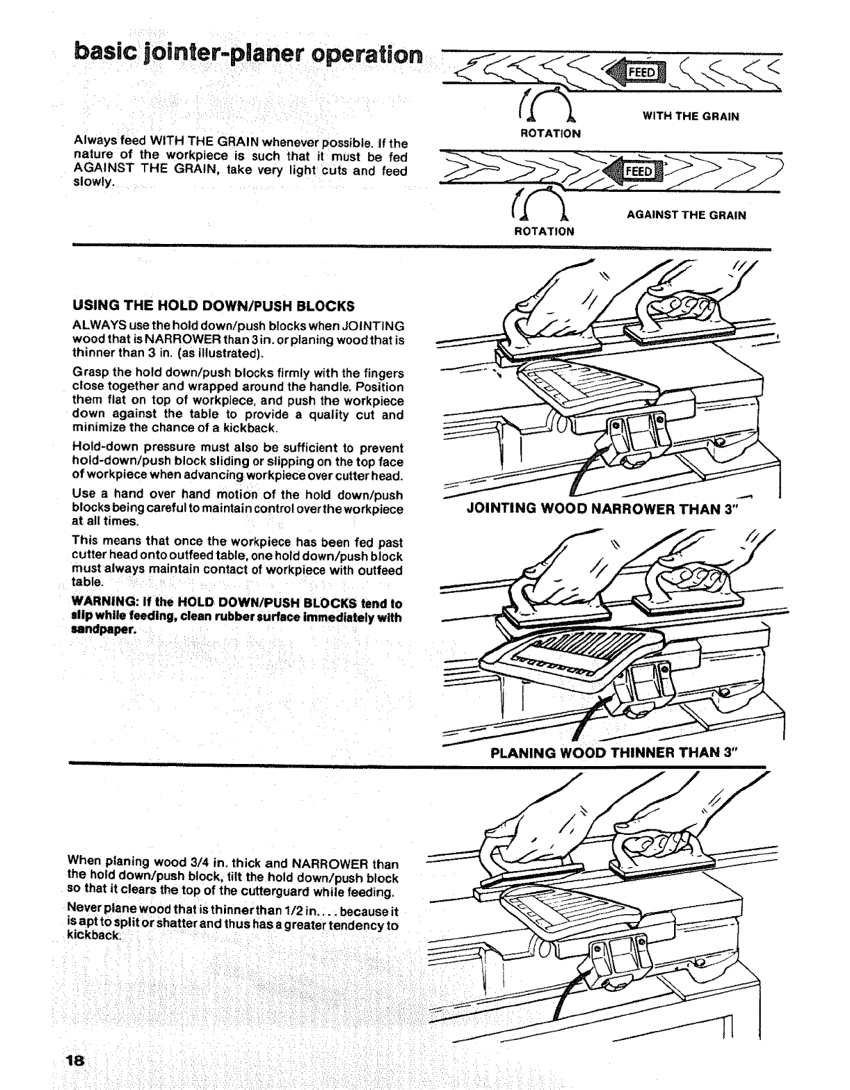
Always feed WITH THE GRAIN whenever possible, if the
nature of the workpiece is such that it must be fed
AGAINST THE GRAIN, take very light Cuts and feed
slowly. _ _.....
ROTATION
ROTATION
WITH THE GRAIN
AGAINST THE GRAIN
USING THE HOLD DOWN/PUSH BLOCKS
ALWAYS use the hold down/push blocks when JOINTING
wood that is NARROWER than 3 in. or planing wood that is
thinner than 3 in. (as illustrated).
Grasp the hold down/push blocks firmly with the fingers
close together and wrapped around the handle. Position
them flat on top of workpiece, and push the workpiece
down against the table to provide a quality cut and
minimize the chance of akickback.
Hold-down pressure must also be sufficient to prevent
hold-down/push block sliding or slipping on the top face
of workpiece when advancing workpiece over cutter head.
Use a hand over hand motion of the hold down/push
blocks being careful to maintain Control over the workpiece
at all times.
This means that once the workpiece has been fed past
cutter head ontooutfeed table, one hold down/push block
must always maintain contact of workpiece with outfeed
table.
WARNING: If the HOLD. DOWN/PUSH BLOCKS tend to
slip while feeding, clean rubber surface Immediately with
sandpaper.
JOINTING WOOD NARROWER THAN 3"
When planing wood 3/4 in. thick and NARROWER than
the hold down/push block, tilt the hold down/push block
so that it clears the top of the cutterguard while feeding,
Never plane wood that is thinner than 1/2 in .... because it
is apt to Split or shatter and thus has a greater tendency to
kickback_
PLANING WOOD THINNER THAN 3"
18
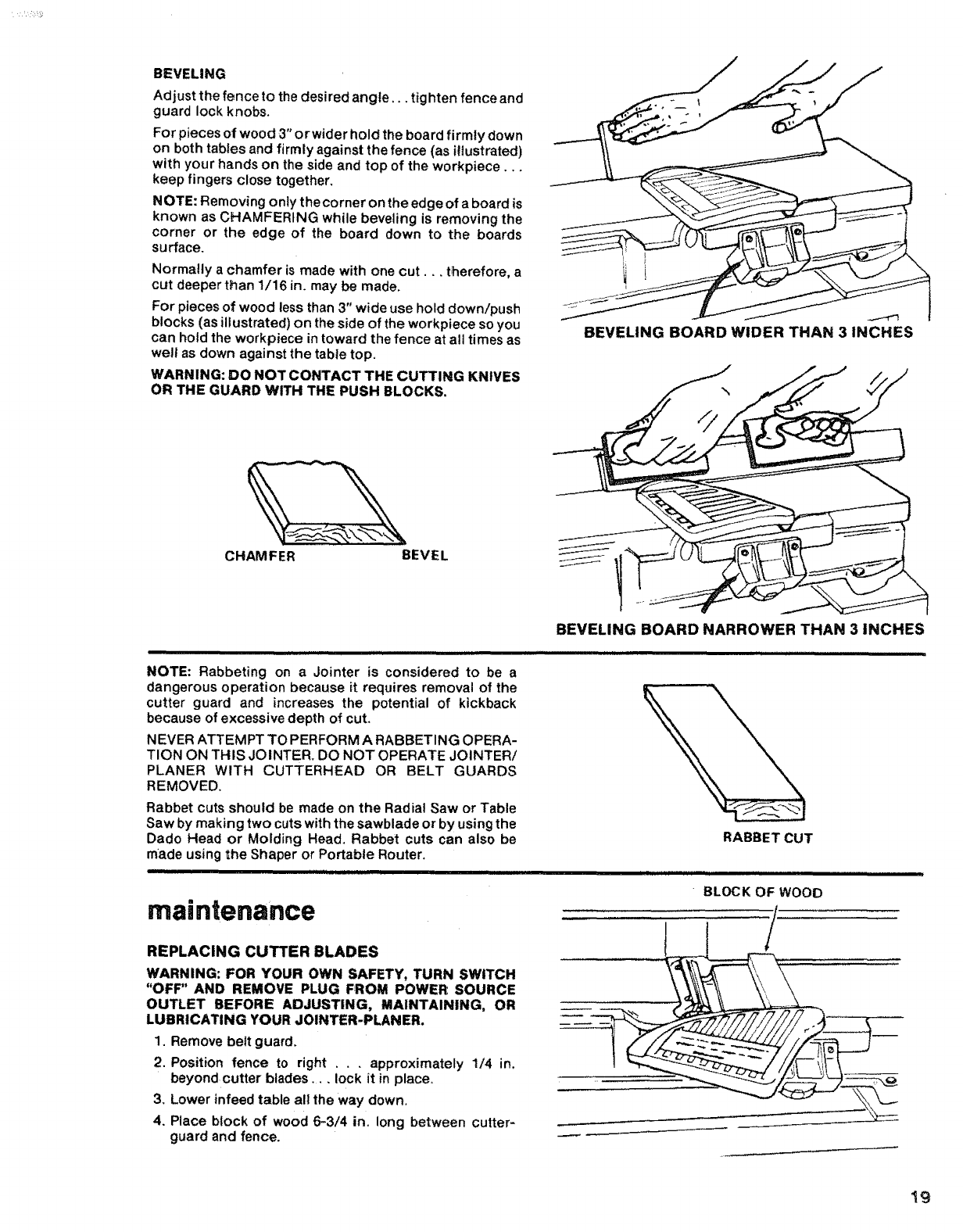
BEVELING
Adjust the fence to the desired angle.., tighten fence and
guard lock knobs,
For pieces of wood 3" or wider hold the board firmty down
on both tables and firmly against the fence (as i!lustrated)
with your hands on the side and top of the workpiece,..
keep fingers close together.
NOTE: Removing only the corner on the edge of a board is
known as CHAMFERING while beveling is removing the
corner or the edge of the board down to the boards
surface.
Normally a chamfer is made with one cut.,, therefore, a
cut deeper than 1/16 in. may be made,
For pieces of wood less than 3" wide use hold down/push
blocks (as illustrated) on the side of the workpiece so you
can hold the workpiece in toward the fence at all times as
welt as down against the table top,
WARNING: DO NOT CONTACT THE CUTTING KNIVES
OR THE GUARD WITH THE PUSH BLOCKS,
BEVELING BOARD WIDER THAN 3 INCHES
CHAMFER BEVEL
BEVELING BOARD NARROWER THAN 3 INCHES
NOTE: Rabbeting on a Jointer is considered to be a
dangerous operation because it requires removal of the
cutter guard and increases the potential of kickback
because of excessive depth of cut.
NEVER ATTEMPT TO PERFORM A RABBETING OPERA-
TION ON THIS JOINTER, DO NOT OPERATE JOINTERi
PLANER WITH CUTTERHEAD OR BELT GUARDS
REMOVED.
Rabbet cuts should be made on the Radial Saw or Table
Saw by making two cuts with the sawblade or by using the
Dado Head or Molding Head, Rabbet cuts can also be
made using the Shaper or Portable Router.
maintenance
REPLACING CUTTER BLADES
WARNING: FOR YOUR OWN SAFETY, TURN SWITCH
"OFF" AND REMOVE PLUG FROM POWER SOURCE
OUTLET BEFORE ADJUSTING, MAINTAINING, OR
LUBRICATING YOUR JOINTER-PLANER.
1, Remove belt guard.
2. Position fence to right ..,approximately 1/4 in.
beyond cutter blades .... lock it in place,
3, Lower infeed table all the way down,
4, Place block of wood 6-3/4 in, long between cutter-
guard and fence.
,i ii i ii i llll illlllllllllllll
RABBET CUT
BLOCK OF WOOD
/
19
:rnaintenance
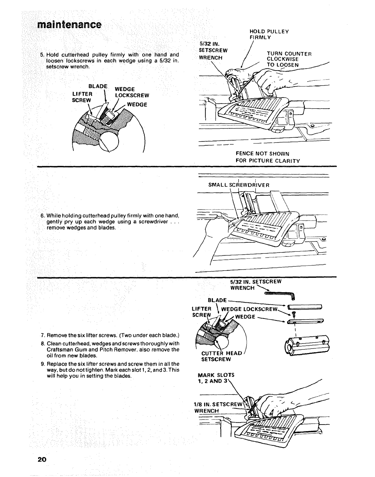
5. Hold cutterhead pulley firmly with one hand and
loosen Iockscrews in each wedge using a 5/32 in.
setscrew wrench.
BLADE WEDGE
LI FTE R LOCKSCR EW
SCREW WEDGE
HOLD PULLEY
FIRMLY
5/32 IN. /
SETSCREW TURN COUNTER
WRENCH CLOC KWISE
\,j TOLOOSEN
_,- ,, .I _ . _ .......
• i
FENCE NOT SHOWN
FOR PICTURE CLARITY
]111 iii ,i i ii llul i
I I
SMALL SCREWDRIVER
6. While holding cutterhead pulley firmly with one hand,
gently pry up each wedge using ascrewdriver..
remove wedges and blades,
7. Remove the six lifter screws. (Two under each blade.)
8. Clean cutterhead, wedges and screws thoroughly with
Craftsman Gum and Pitch Remover. also remove the
oil from new blades.
"SETSCREW ....
5/32 IN.
WRENCH
BLADE ------
LIFTER WEDGE LOCKSCREW._L_ "---'J
--.--..,_..,...,,. ,,, -,
t
CUTrER HEAD
SETSCREW
9. Replace the six lifter screws and screw them in all the
way, but do not tighten. Mark each slot 1, 2, and 3. This
witl help you in setting the blades.
• , ,_ : : , i: _, •,:, : • •
_ _/ii:i: :'_i_ /i:__i_i_!i_i}iiii_'_:: _:_i_i__?_:! _.....
MARK SLOTS
20 ¸
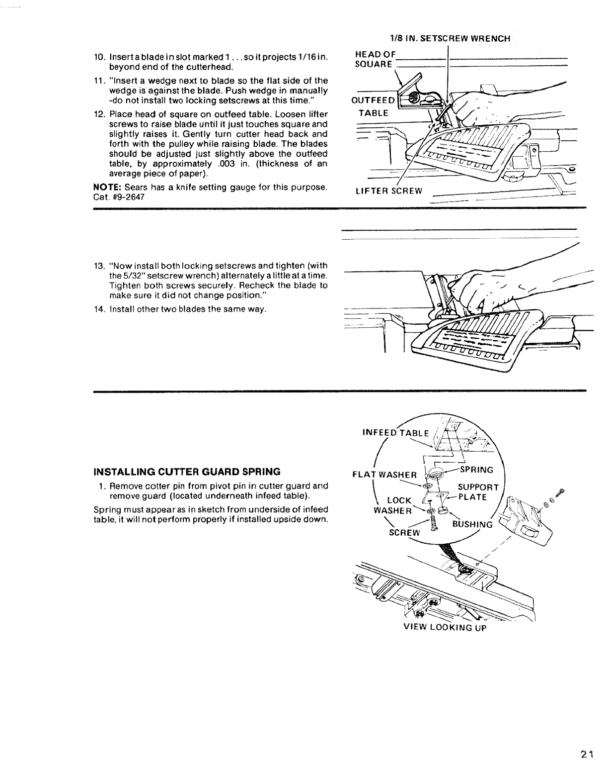
10. Insert a blade in slot marked 1. ,, so it projects 1/16 in,
beyond end of the cutterhead.
11, "Insert a wedge next to blade so the flat side of the
wedge is against the blade. Push wedge in manualy
-do not install two locking setscrews at this time."
12. Place head of square on outfeed table, Loosen lifter
screws to raise blade _ntil it just touches square and
slightly raises it, Gently turn cutter head back and
forth with the pulley while raising blade. The blades
should be adjusted just slightly above the outfeed
table, by approximately ,003 in, (thickness of an
average piece of paper).
NOTE: Sears has aknife setting gauge for this purpose.
Cat. #9-2647
1/8 IN. SETSCREW WRENCH
HEAD OF
SQUARE
LIFTER SCREW
ii ,1111iiii
13, "Now install both locking setscrews and tighten (with
the 5/32" setscrew wrench) alternately a little at a time.
Tighten both screws securely, Recheck the blade to
make sure it did not change position."
14. Install other two blades the same way.
INSTALLING CUTTER GUARD SPRING
1, Remove cotter pin from pivot pin in cutter guard and
remove guard (located underneath infeed table).
Spring must appear as in sketch from underside of infeed
table, it will not perform properly if installed upside down,
INFEED_.
/
I\
f=PRINGI
\ suPPORT/
sc"Lw- i
VIEW LOOKING UP
2!
i i :
•• /_• !•: i/: ¸ _ :•
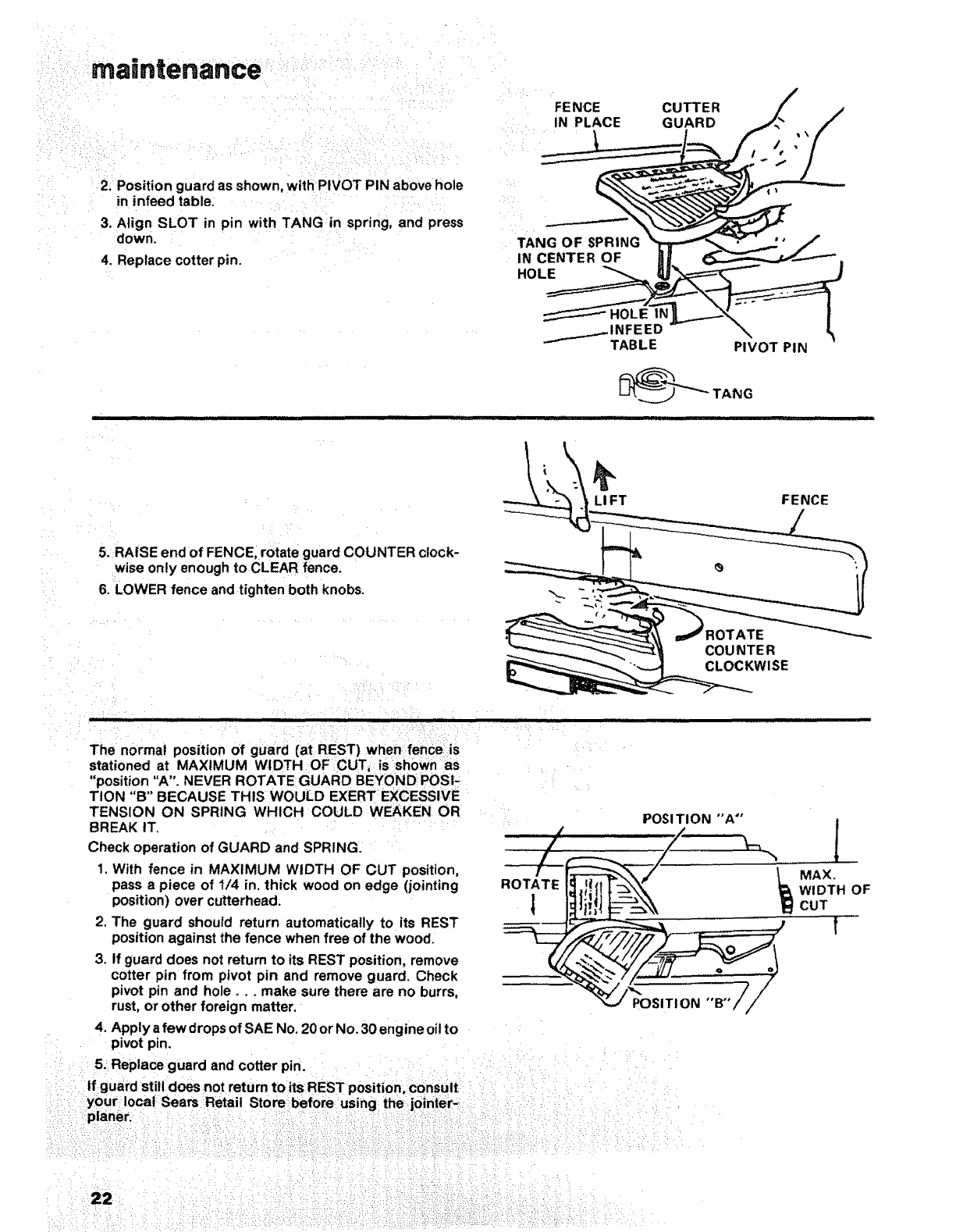
:2: Position guard as shown, wtthPIVOT PIN above hole
in infeed table: :
3. Align SLOT in pin with TANG in spring, and press
down, :
4. Replace cotter pin.
FENCE
IN PLACE
i
TANG OF SPRING
IN CENTER OF
HOLE
CUTTER
GUARD
_INFEED
TABLE PIVOT PIN
_"""'_ TANG
5. RAISE end of FENCE, rotate guard COUNTER clock-
wise only enough to CLEAR fence.
6. LOWER fence and tighten both knobs.
H••• •
LIFT FENCE
:= :
i i iiii illl i • ,,i,,,,ll Hi
COUNTER
CLOCKWISE
WIDTH OF
il il II I Hill I IIIIIIIIIIIIIIIIIIIIII II I IIIII III II I IIII I IIII
........ ::: ::
: i :: ....
The normal position of guard (at REST) when fence js :
stationed at MAXIMUM WIDTH OF CUT_: issh0wn as
'position "A". NEVER ROTATE GUARD BE¥0NDI POSI_ ::
TION "B" BECAUSE THIS WOULD EXERT EXCESSIVE _
TENSION ON SPRING WHICH COULD WEAKENOR_.: POSITION "'A"
BREAK IT.
Check operation of GUARD and SPRING.
1. With fence in MAXIMUM WIDTH OF CUT position,
pass a piece of 1/4 in, thick wood on edge (jointing
position) over cutterhead.
2. The guard should return automatically to its REST
position against the fence when free of the wood.
3. If guard does not return to its REST position, remove
cotter pin from pivot pin and remove guard. Check
pivot pin and hole.., make sure there are no burrs,
rust, or other foreign matter. POSITION "B"
4. Apply afew drops of SAE No. 20 or No. 30 engine oil to
pivot pin.
:. 5.: Replace :guard and cotter pin. _i i _
_:::::i;_ tfguard sti!l d°es not return to its REST position,conSult: :: i:: ::
:;::::::your: local: Sears Retail Store: before: using the: j0intet-:: ::: :: :: :
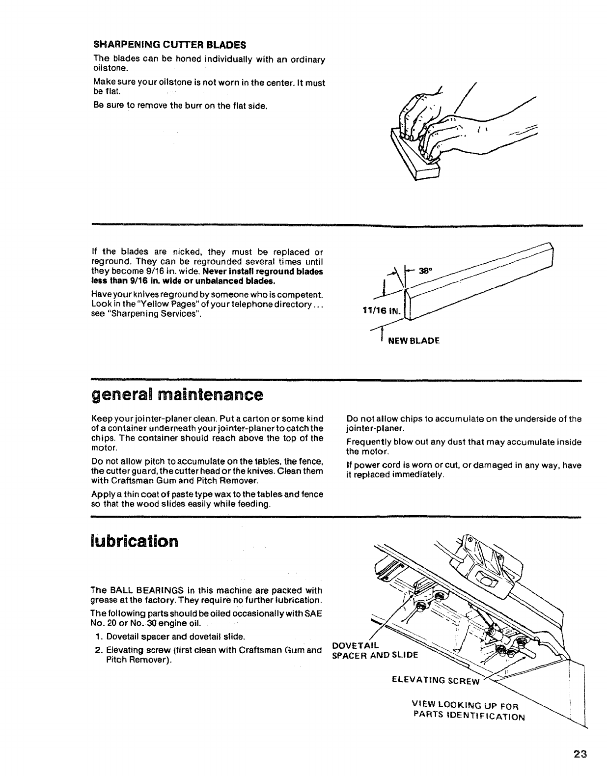
SHARPENII_GCUTTERBLADES
The blades can be honed individually with an ordinary
oilstone.
Make sure your oilstone is not worn in the center. It must
be flat.
Be sure to remove the burr on the flat side.
Ill I Illlll I I I II Illm 'l_'
if the blades are nicked, they must be replaced or
reground. They can be regrounded several times until
they become 9/t6 in. wide. Never install reground blades
less than 9/16 in. wide or unbalanced blades.
Have your knives reground by someone who is competent.
Look in the"Yellow Pages" of you r telephone directory...
see "Sharpening Services". 11116 IN.
NEW BLADE
i , ,,,,,,,,,,,,,,,,,,,, .........
general maintenance
Keep your jot nter-planer clean. Put a carton or some kind
of a container underneath your jointer-planer to catch the
chips. The container should reach above the top of the
motor.
Do not allow pitch to accumulate on the tables, the fence,
Do not allow chips to accumulate on the underside of the
jointer-planer.
Frequently blow out any dust that may accumulate inside
the motor.
If power cord is worn or cut, or damaged in any way, have
the cutter guard, the cutter head or the knives. Clean them
with Craftsman Gum and Pitch Remover.
Apply a thin coat of paste type wax to the tables and fence
so that the wood slides easily while feeding.
' ii iiiiiiipllll iii iiii ,111 i ii IIIImll!lllln
lubrication
it replaced immediately.
I II I I I L I L LLII lllllllll]llJll l
The BALL BEARINGS in this machine are packed with
grease at the factory. They requi re no further lubrication.
The following parts should be oiled occasionally with SAE
No. 20 or No. 30 engine oil.
1. Dovetail spacer and dovetail slide,
2, Elevating screw (first clean with Craftsman Gum and
Pitch Remover).
DOVETAIL
SPACER AND SLIDE
ELEVATING SCREW
VIEW LOOKING UP FOR
PARTS IDE NTI FICATION H
23
lubrication
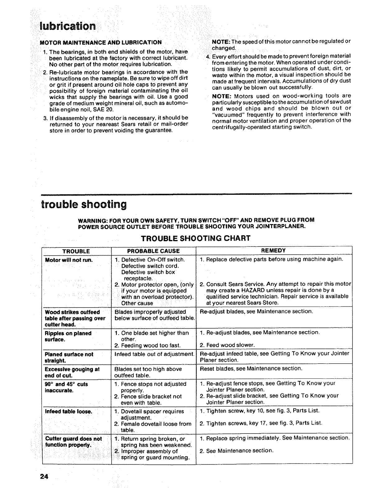
MOTOR MAINTENANCE AND LUBRICATION
1. The bearings, in both end shields of the motor, have
been lubricated at the factory with correct lubricant.
No other part of the motor requires lubrication.
2. Re-lubricate motor bearings in accordance with the
instructions on the nameplate. Be sure to wipe off dirt
or grit if present around oil hole caps to prevent any
possibility of foreign material contaminating the oil
wicks that supply the bearings with oil. Use a good
grade of medium weight mineral oit, such as automo-
bile engine noit, SAE 20.
3. If disassembly of the motor is necessary, it should be
returned to your neareast Sears retail or mail-order
store in order to prevent voiding the guarantee.
NOTE: The speed of this motor can not be regulated or
changed.
4: Every effort should be madeto prevent foreign material
from entering the motor. When operated under condi-
tions likely to permit accumulations of dust, dirt, or
waste within the motor, a visual inspection should be
made at frequent intervals. Accumulations of dry dust
can usually be blown out successfully.
NOTE: Motors used on wood-working tools are
particularly susceptible to the accumulation of sawdust
and wood chips and should be blown out or
"vacuumed" frequently to prevent interference with
normal motor ventilation and proper operation of the
centrifugally-operated starting switch.
.................... iiip |ll=,l
trouble shooting
iiiillll ,.ll |. i ill.i ill. jll ill i i i ill
WARNING: FOR YOUR OWN SAFETY, TURI_ SWITCH "OFF" AND REMOVE PLUG FROM
POWER SOURCE OUTLET BEFORE TROUBLE SHOOTING YOUR JOINTERPLANER,
TROUBLE SHOOTING CHART
TROUBLE PROBABLE CAUSE REMEDY
Motor will not run. 1, Defective On-Off switch. ' "' i'i Replace defective parts before using machine again.
..... .... Defective switch cord.
'Defective switch box:
............. receptacle.
2. Motor protector open, ionly
if your motor is equipped
' :_: : With an overload ProteCtor).
Other Cause :::,:::i:,:,,
Wood strikes ouffeed ......................Blades improperly adjusted
table after passing over below surface of outfeed table,i
cutter head. .....
Ripples on planed 1. One blade set higher than
surface, other.
2. Feeding wood too fast.
Planed surface not Infeed table out of adjustment.
straight.
Excessive gouging at Blades set too high above
end of cut, ouffeed table.
90° and 45° cuts 1. Fence stops not adjusted
inaccurate, properly.
2. Fence slide bracket not
even with table.
Infeed table loose. 1. Dovetail spacer requires
adjustmenL
i 2_ Female dovetail loose from
................... .... : table.
Cutter guard doesnot : f 1: Return spring broken, or
function properly, 1 i spring has been weakened.
:_. _ ':':: :: 12! Improper assembly of
ii _ :: I:_:: spriSgor guard mounting.
2. Consu_tt Sears Service, Any attempt to repair this motor
may create a HAZARD unless repair is done by a
qualified service technician. Repair service is available
at your nearest Sears Store.
Re-adjust blades, see Maintenance section.
1. Re-adjust blades, see Maintenance section.
2. Feed wood slower.
Re-adjust infeed table, see Getting To Know your Jointer
Planer section.
Reset blades, see Maintenance section.
1. Re-adjust fence stops, see Getting To Know your
Jointer Planer section.
2. Re-adjust slide bracket, see Getting To Know your
Jointer Planer section.
1. Tighten screw, key 10, see fig. 3, Parts List.
2. Tighten screws, key 17, see fig. 3, Parts List.
1."Replace spring immediately. See Maintenance "secti'oni'
2, See Maintenance section.
24

TROUBLE SHOOTING -- MOTOR
NOTE: Motors used on wood-working tools are particularly susceptible to the accumulation
of sawdust and wood chips and should be blown out or "vacuumed" frequently to prevent
interterence with normal motor ventilation and proper operation of the centrifugally-
operated starting switch,
TROUBLE PROBABLE CAUSE
Excessive noise. 1, Motor° 1.
1. 1.
Motor fails to develop
full power, NOTE:
LOW VOLTAGE: (Power
output of motor
decreases rapidly with
decrease in voltage at
motor terminals. For
exampte, a reduction of
10% in voltage causes a
reduction of 19% in
maximum power output
of which the motor is
capable, and a reduction
of 20% in voltage causes
a reduction of 36% in
maximum power output.)
Motor starts slowly
or fails to come up
to full speed.
Motor overheats.
Starting switch in motor
will not operate,
Motor stalls (resulting
in blown fuses or
tripped circuit breakers).
Frequent opening of
fuses or circuit
breakers.
2.
3,
Circuit overloaded with
lights, appliances and other
motors,
Undersize wires or circuit
too long.
General overloading of
power company facilities,
!. Low voltage will not trip
relay,
2. Windings burned out or
open.
3, Starting relay not operating.
1. Motor overloaded.
2. Improper cooling. (Air
circulation restricted
through motor due to
sawdust, accumulating
inside of motor),
1, Burned switch contacts
(due to extended hold-in
periods caused by low line
voltage, etc.).
2. Shorted capacitor.
3. Loose or broken
connections.
1. Starting switch not
operating,
2, Voltage too tow to permit
motor to reach operating
speed.
3. Fuses or circuit breakers
do not have sufficient
capacity.
1. Motor overloaded.
2. Fuses or circuit breakers
do not have sufficient
capacity.
3. Startring switch not
operating (motor does not
reach speed),
REMEDY
Have motor checked by qualified service technician,
Repair service is available at your nearest Sears store,
Do not use other appliances or motors on same circuit
when using the jointer,
2, Increase wire sizes, or reduce length of wiring. See
"Motor Specifications and Electrical Requirements"
section,
3. Request a voltage check from the power company.
!, Request voltage check from the power company.
2_ Have motor repaired or replaced.
3. Have relay replaced.
1, Feed work slower into blade,
2. Clean out sawdust to provide normal air circulation
through motor, See "Maintenance and Lubrication"
section.
1. Have switch replaced and request avoltage check
from the power company.
2, Have capacitor tested and replace if defective.
3. Have wiring checked and repaired.
1, Have switch replaced.
2. Request voltage check from the power company.
3, Install proper size fuses or circuit breakers.
1. Feed work slower.
2. Install proper size fuses or circuit breakers.
3. Have switch replaced.
25
47
9
11
52
51
50
44
16
40
37
36
15
!4
1:
12
23
24
25
48
FIGURE 1
54
55 56 35
32
27
22
26
• i/
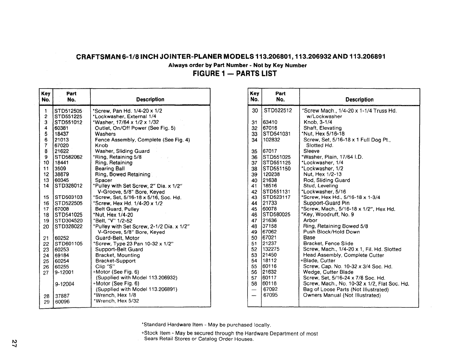
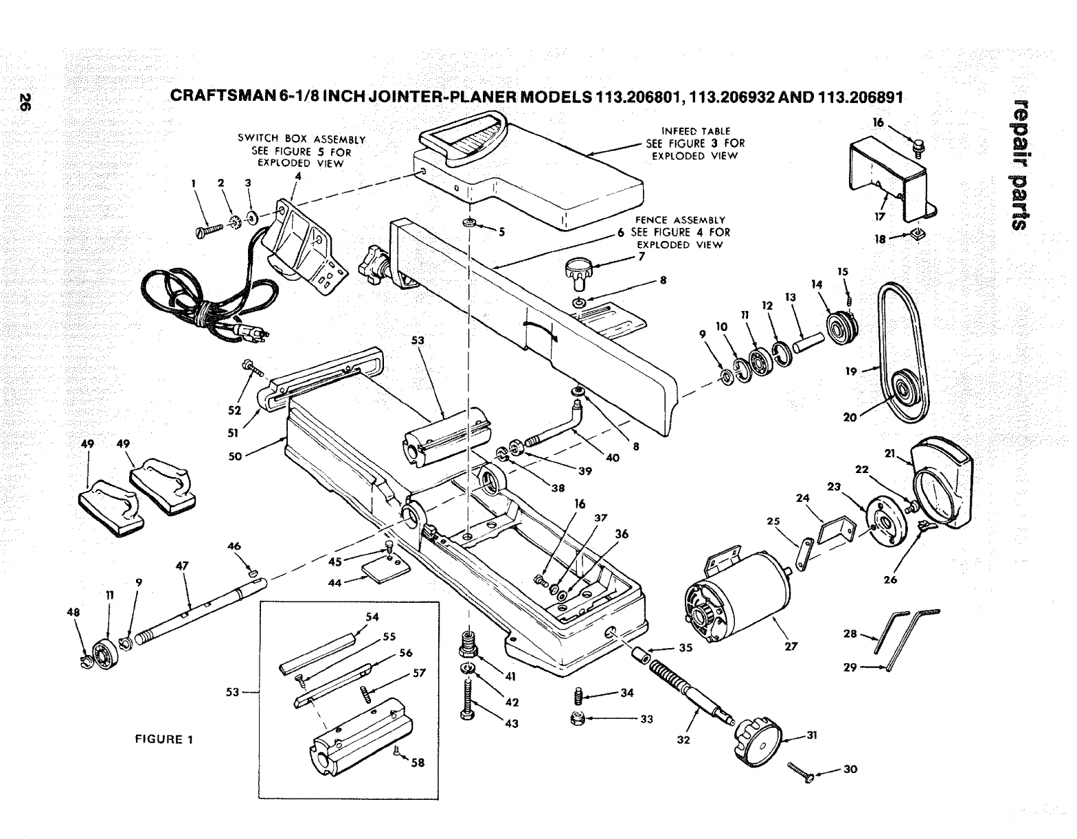
CRAFTSMAN 6-1/8 INCH JOINTER-PLANER MODELS 113.206801,113.206932 AND 113.206891
Always order by Part Number - Not by Key Number
FIGURE 1 -- PARTS LIST
Key Part
NO, No.
1
2
3
4
5
6
7
9
!0
!I
12
13
14
15
16
17
18
19
20
2!
22
23
24
25
26
27
28
29
STD512505
STD551225
STD551012
60381
18437
21013
67020
21622
STD582062
18441
3509
38879
60345
STD328012
STD503103
STD522505
67008
STD541025
STD304520
STD328022
60252
STD601105
60253
69184
60254
60255
9-12001
9-12004
37887
60096
Description
•. 11
"Screw, Pan Hd, 1/4-20 x 1/2
•Lockwasher, External 1/4
•Washer, 17/64 x 1/2 × t/32
Outlet, On/Off Power (See Fig. 5)
Washers
Fence Assembly, Complete (See Fig. 4)
Knob
Washer, Sliding Guard
•Ring, Retaining 5/8
Ring, Reta;ning
Bearing Bali
Ring, Bowed Retaining
Spacer
•Pulley with Set Screw, 2" Dia, × 112"
V-Groove, 5/8" Bore, Keyed
"Screw, Set, 5/16-18 x5/16, Soc. Hd.
•Screw, Hex Hd. t/4-20 x 1/2
Belt Guard, PulLey
•Nut, Hex 1/4-20
•Belt, "V" 1/2-52
"Pulley with Set Screw, 2-1/2 Dia. x 1/2"
V-Groove, 5/8" Bore, Keyed
Guard-Belt, Motor
•Screw, Type 23 Pan 10-32 x 1/2"
Support-Belt Guard
Bracket, Mounting
Bracket-Support
Clip "S"
+Motor (See Fig. 6)
(Supplied with Model 113.206932)
+Motor (See Fig. 6)
(Supplied with Modet 113.206891)
•Wrench, Hex 1/8
•Wrench, Hex 5/32
Key Part
No. No.
30 STD522512
31 63410
32 67016
33 STD541031
34 102832
35 67017
36 STD551025
37 STD551125
38 STD551150
39 120238
40 21638
41 18516
42 STD551131
43 STD523117
44 21733
45 60078
46 STD580025
47 21636
48 37158
49 67062
50 67021
51 21237
52 132275
53 21450
54 18112
55 80116
56 21632
57 60117
56 60118
-- 67092
67095
Description
nnl ....
*Screw Mach., 1/4-20 x 1-1/4 Truss Hd.
w/Lockwasher
Knob, 3-1/4
Shaft, Elevating
*Nut, Hex 5/16-18
Screw, Set, 5/16-18 x 1 Full Dog Pt.,
Slotted Hal.
Sleeve
*Washer, Piain, 17/64 I.D.
*Lockwasher, !/4
*Lockwasher, 1/2
Nut, Hex 1/2-13
Rod, Sliding Guard
Stud, Leveling
*Lockwasher, 5/16
*Screw, Hex Hd., 5/16-!8 x 1-3/4
Support-Guard Pin
*Screw, Mach., 5/16-18 x 1/2", Hex Hd.
*Key, Woodruff, No. 9
Arbor
Ring, Retaining Bowed 5/8
Push Block/Hold Down
Base
Bracket, Fence Slide
Screw, Mach., t/4-20 x 1, Fil. Hd. Slotted
Head Assembly, Complete Cutter
+Blade, Cutter
Screw, Cap. No. 10-32 x 3/4 Soc. Hal.
Wedge, Cutter Blade
Screw, Set, 5/16-24 x 7/8 Soc. Hal.
Screw, Mach., No. 10-32 × 1/2, Flat Soc. Hd,
Bag of Loose Parts (Not Illustrated)
Owners Manual {Not Illustrated)
t_
-4
*Standard Hardware Item - May be purchased locally.
+Stock Item - May be secured through the Hardware Department of most
Sears Retail Stores or Catalog Order Houses.

repair parts CRAFTSMAN 6'1/8 INCH JOINTER-PLANER
MO D ELS 113.206801,113.206932 AN D 113.206891
!
2
2
4•
FIGURE 2
FIGURE 2 mLEGS PARTS LiST
Key
No.
1
2
3
4
5
6
7
8
9
10
Part
No.
67033
60314
STD55t225
STD541025
67032
62614
62204
67034
STD541250
803835
67035
Description
Stiffener, End
e Screw, Truss Hd 1/4-20 x 5/8
e*Lockwasher, 1/4 External
e'Nut, Hex 1/4-20
Stiffener, Side
Leg
eClip, Cord
Support, Motor
e'Nut, Hex Hal. 1/2-13
• Foot, Leveling
Bag of Loose Parts (Not lltus.)
HARDWARE FOR MOUNTING TOOL AND MOTOR
-- STD532507
STD55123I
STD551031
STD523120
STD541231
e'Bolt, Carriage 5116-18 x 3/4
e*Lockwasher, 5/16 External
e'Washer, 11/32 x 11/16 x 1/16
e'Screw, Hex Hd. 5/16-18 x 2
e'Nut, Hex 5/16-18
28
••;_•:• • • •: •: ::• ) •;:: ,: • : i ::: :i !• ••i• I•L i:•: ::
•Supplied in Loose Parts Bag 67035
*Standard Hardware Item - May be Purchased Locally.
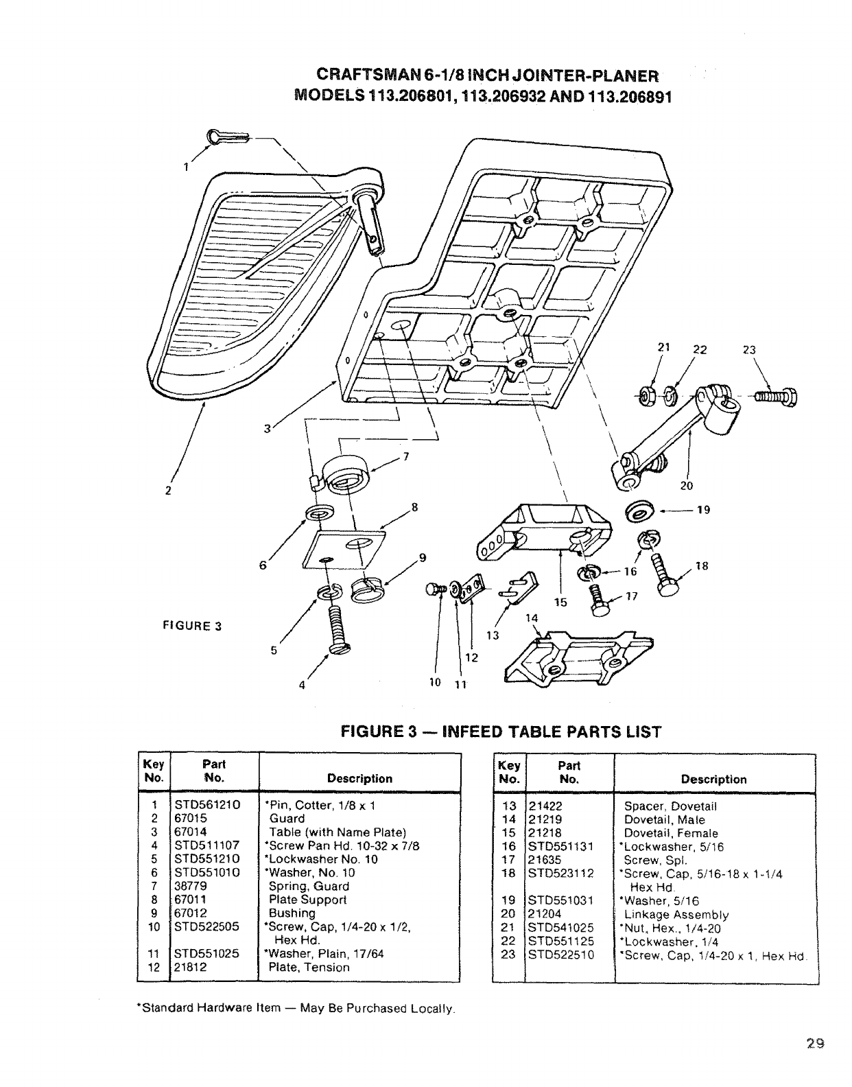
CRAFTSMAN 6-1/8 INCH JOINTER-PLANER
MODELS 113.206801, 113.206932 AND 113.206891
_---__- "21 22
20
2 \
FIGURE 3 5 3
23
Key Part
No. No.
i,i
1STD561210
2 67015
3 67014
4 STD511107
5 STD551210
6 STD551010
7 38779
8 6701t
9 167012
10 STD522505
11 STD551025
12 21812
FIGURE 3 -- INFEED TABLE PARTS LIST
Description
lllll lip
*Pin, Cotter, t/8 x1
Guard
Table (with Name Plate)
*Screw Pan Hd 10-32 x 7/8
*Lockwasher No 10
*Washer, No 10
Spring, Guard
Plate Support
Bushing
*Screw, Cap, 1/4-20 x 1/2,
Hex Hd.
*Washer, Plain, 17164
Plate, Tension
Key
No. Part
No.
13 21422
14 21219
15 21218
16 STD551131
17 21635
18 STD523112
19 STD55!031
20 2!204
2! STD54t025
22 STD551125
23 STD522510
Description
Spacer, Dovetail
Dovetail, Male
Dovetail, Female
*Lockwasher, 5/16
Screw, Spl.
*Screw, Cap, 5/16-I8 x 1-1/4
Hex Hd
*Washer, 5/16
Linkage Assembly
*Nut, Hex., t/4-20
*Lockwasher, I/4
"Screw, Cap, 1t4-20 x 1, He× Hd.
*Standard Hardware Item -- May Be Purchased Loca!ly.
29
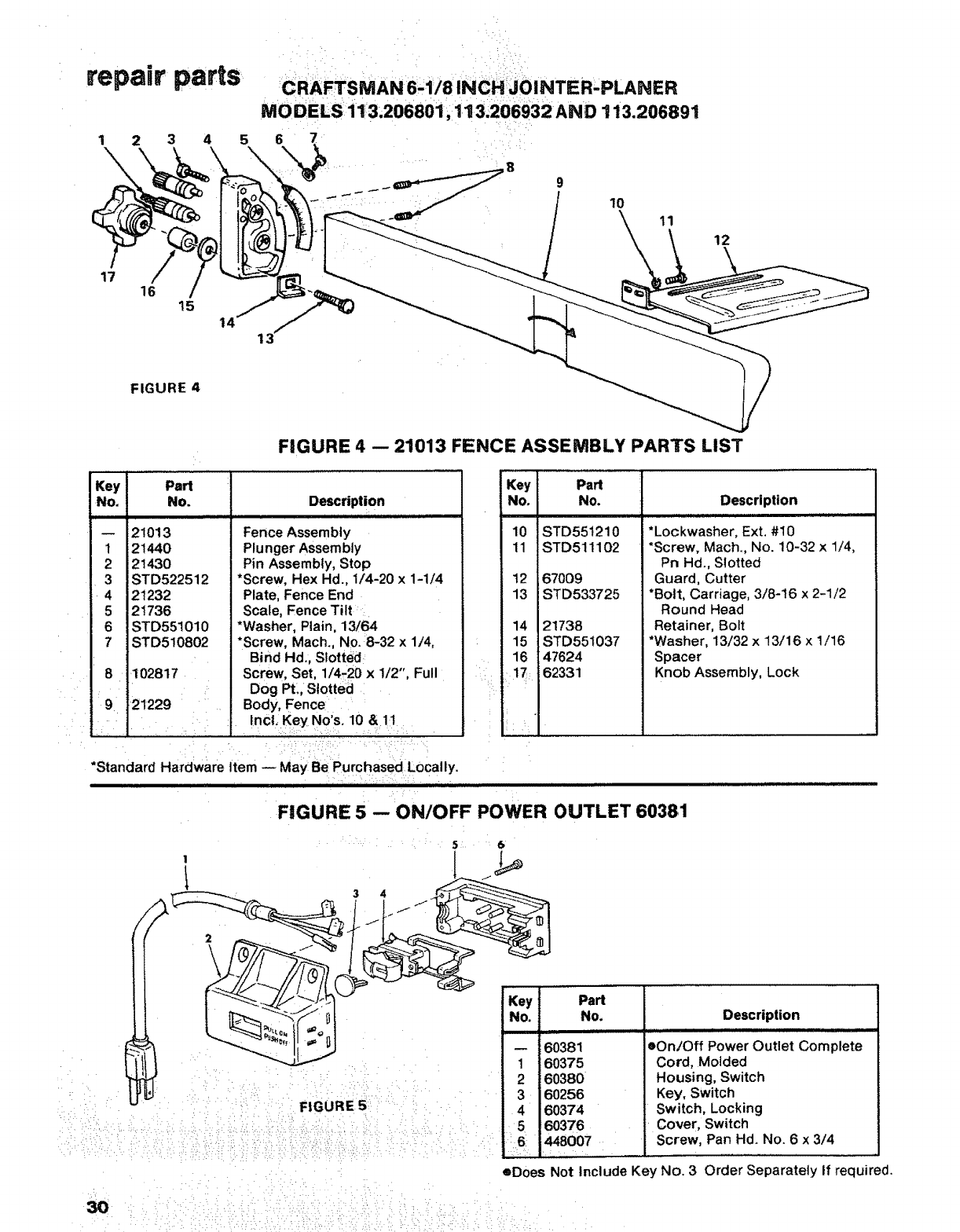
repair parts
12345
17 16 15
12
FIGURE 4
FIGURE 4 -- 21013 FENCE ASSEMBLY PARTS LIST
Key Part
No, No.
,,,,,,,, ]i
21013
t21440
221430
_STD522512
21232
21736
STD551010
7 STD510802
8 ••i 102817
21229
Description
Fence Assembly
Plunger Assembly
Pin Assembly, Stop
*Screw, Hex Hd., 1/'4-20 x1-1/4
Plate, Fence End
Scale, Fence Tilt _
*Washer, Plain, 13/64
*Screw, Mach., No.;8-32 x 1/4,
Bind Hd., Slotted
Screw, Set, 1/4.20 x 1/2", Full
Dog PL, Slotted
Body, Fence
IoCii Key.o's.10 !1
*Standard Hm'dware Item -- May BePurchased Locally.
'111 I I f ill l I I III: I I li=l IIIIIIIIIIIIIIIIIIlill IIIIIIIIIIIJl
Key Part
No. No.
10 STD551210
11 STD511102
12 67009
13 STD533725
14 21738
15 STD551037
16 47624
17:62331
II
FtGURE 5 -- ON/OFF POWER OUTLET 60381
56
Key
No.
Description
*Lockwasher, Ext. #10
*Screw, Mach., No. 10-32 x 1/4,
Pn Hd., Slotted
Guard, Cutter
*Bolt, Carriage, 3/8-16 x 2-1/2
Round Head
Retainer, Bolt
*Washer, 13/32 x 13/16 x 1/16
Spacer
Knob Assembly, Lock
Part
No.
60381
60375
60380
60256
60374
60376
448007
Description
eOn/Off Power Outlet Complete
Cord, Molded
Housing, Switch
Key, Switch
Switch, Locking
Cover, Switch
Screw, Pan Hd. No. 6 x 3/4
1
2
•5
eDoes Not Include Key No. 3 Order Separately If required.
3O
] 2
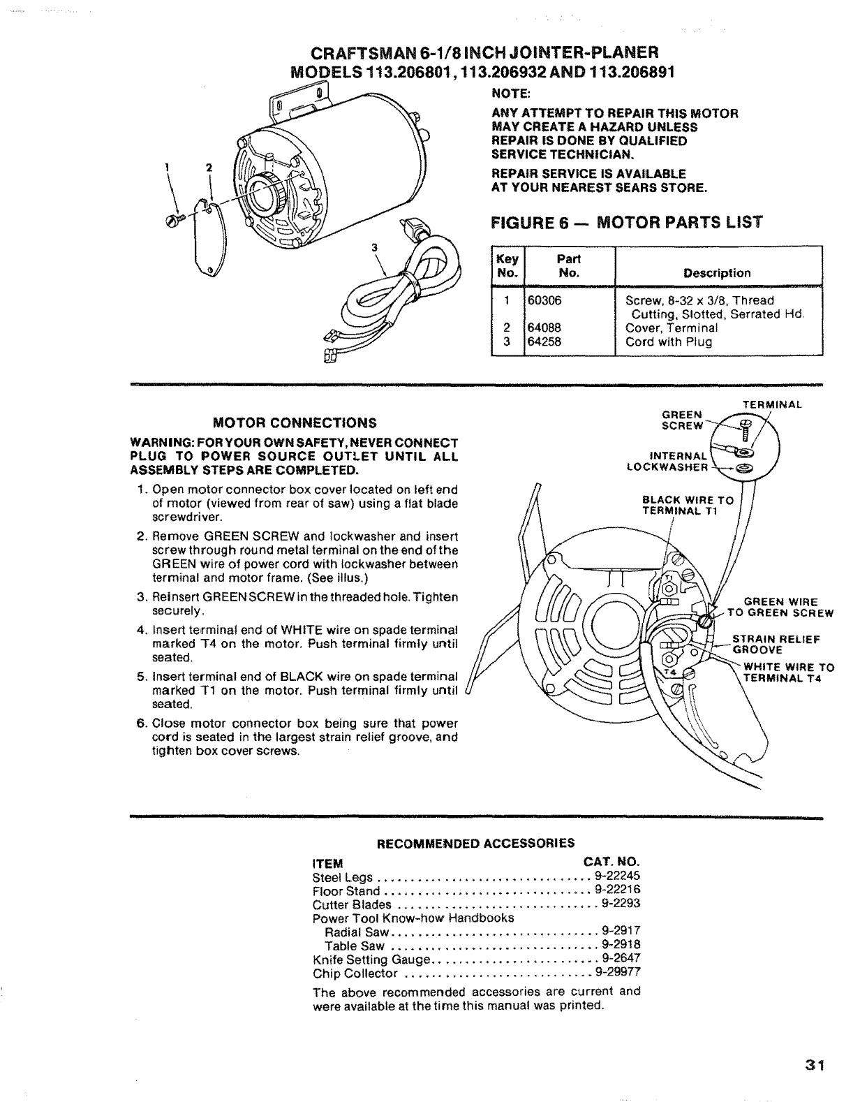
CRAFTSMAN 6-1/8 INCH JOINTER-PLANER
MODELS 113.206801,113.206932 AND 113.206891
NOTE:
ANY ATTEMPT TO REPAIR THIS MOTOR
MAY CREATE A HAZARD UNLESS
REPAIR IS DONE BY QUALIFIED
SERVICE TECHNICIAN.
REPAIR SERVICE IS AVA|LABLE
AT YOUR NEAREST SEARS STORE.
FIGURE 6 -- MOTOR PARTS LIST
Key PaH
No. No.
1 60306
264088
3 64258
Description
Screw, 8-32 x 3/8, Thread
Cutting, Slotted, Serrated Hd
Cover, Terminal
Cord with Plug
MOTOR CONNECTIONS
WARN I NG: FOR YOUR OWN SAFETY, NEVER CONNECT
PLUG TO POWER SOURCE OUTLET UNTIL ALL
ASSEMBLY STEPS ARE COMPLETED.
1, Open motor connector box cover located on left end
of motor (viewed from rear of saw) using a flat blade
screwdriver.
2, Remove GREEN SCREW and lockwasher and insert
screw through round metal terminal on the end of the
GREEN wire of power cord with !ockwasher between
terminal and motor frame. (See illus.)
3, Reinsert GREEN SCREW in the threaded hole. Tighten
securely.
4, Insert te,rminat end of WHITE wire on spade terminal
marked T4 on the motor. Push terminal firmly until
seated.
5, Insert terminal end of BLACK wire on spade terminal
marked T1 on the motor, Push terminal firmly until
seated.
6. Close motor connector box being sure that power
cord is seated in the largest strain relief groove, and
tighten box cover screws,
ii i 'IIH I
TERMINAL
GREEN
INTERNAL
LOCKWASHER
GREEN WIRE
-TO GREEN SCREW
STRAIN RELIEF
WHITE WIRE TO
TERMINAL T4
RECOMMENDED ACCESSORIES
ITEM CAT. NO.
Steel Legs ................................ 9-22245
Floor Stand ............................... 9-22216
Cutter Blades .............................. 9-2293
Power Tool Know-how Handbooks
Radial Saw ............................... 9-2917
Table Saw ............................... 9-2918
Knife Setting Gauge ......................... 9-2647
Chip Collector ............................ 9-29977
The above recommended accessories are current and
were available at the time this manual was printed,
31

owners
manual
SERVICE
MODEL NO.
113.206932
JOINTER/PLANER WITH
LEGS AND MOTOR
113.206891
JOINTER/PLANER WITH
LEGS AND MOTOR
HOW TO ORDER
REPAIR PARTS
6-1/8 raNCHJOUNTER-PLANER
Now that you have purchased your jointer-planer, should a
need ever exist for repair parts or service, simply contact
any Sears Service Center and most Sears, Roebuck and Co.
stores. Be sure to provide all pertinent facts when you call
or visit.
The model number of your 6-1/8 inch jointer-planer will be
found on a plate attached to your base.
WHEN ORDERING REPAIR PARTS, ALWAYS GIVE THE
FOLLOWING INFORMATION:
PART NUMBER PART DESCRIPTION
MODEL NUMBER
1t 3.206801
113.206932
113.206891
NAME OF ITEM
6=1/8 INCH JOINTER-PLANER
All parts listed may be ordered from any Sears Service
Center and most Sears stores. If the parts you need are not
stocked locally, your order will be electronically transmitted
to a Sears Repair Parts Distribution Center for handling.
Sold by SEARS, ROEBUCK AND CO., Chicago, IL. 60684 U.S.A.
Part No. 67095 Form No. SP4925-2 Printed in U.S.A. 3/8f
