Craftsman 113228162 User Manual WOOD LATHE Manuals And Guides L0803531
CRAFTSMAN Lathe Manual L0803531 CRAFTSMAN Lathe Owner's Manual, CRAFTSMAN Lathe installation guides
User Manual: Craftsman 113228162 113228162 CRAFTSMAN WOOD LATHE - Manuals and Guides View the owners manual for your CRAFTSMAN WOOD LATHE #113228162. Home:Tool Parts:Craftsman Parts:Craftsman WOOD LATHE Manual
Open the PDF directly: View PDF ![]() .
.
Page Count: 35
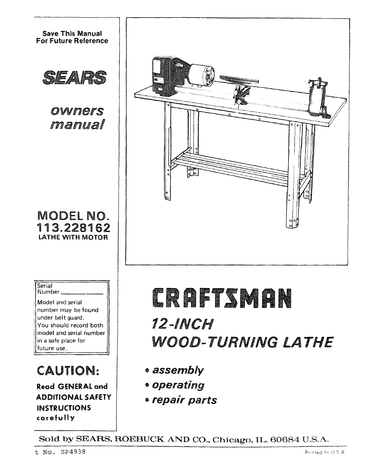
Save This Manual
For Future Reference
MODEL NO.
313.228362
LATHE WITH MOTOR
[serial
! Number
Model and serial
number may be found
under belt guard.
You should record both
model and serial number
in a safe place for
future use.
CAUTION. O
Read GENERAL and
ADDITIONAL SAFETY
INSTRUCTIONS
cerefully
!2-INCH
WOOO-TURNING [A THE
*assembly
,operating
®repair parts
Sold by SEARS, ROEBUCK AND CO., Chicago, IL. 60684 U.S.A.
t No. SP4938 _e_ ,'<_
"FULL ONE YEAR WARRANTY ON CRAFTSMAN WOOD LATHE
if within One year from the date of purchsse, this Craftsman Wood L_the fails due to adefect in material or
workmanship. Sears will repair it, free of cha rge.
WARRANTY SERVICE IS AVAILABLE BY SIMPLY CONTACTING THE NEAREST SEARS SERVICE
CENTER/DEPARTMENT THROUGHOUT THE UNITED STATES.
THIS wARRANTY APPLtES ONLY WHILE THIS PRODUCT IS iN USE'IN THE UNITED STATES.
This warranty gives you =pecifi0 legal rights, and you may atso have other rights which vary from state to state.
: SEARS, ROEBUCK AND CO., D/817 WA HOFFMAN ESTATES, IL 60195
general safety instructions for
1. KNOW. YOUR LATHE 13.
Read and understand owner's manual and labels affixed to
the tool, Learn its apphcation and imitations as well as _ts
specific Potential hazards peculiar to this tool. 14.
2. GROUND THE LATHE
This Lathe is equipped wi_h an approved 3-conductor 15.
cord and a3-prong grounding type plug to fit the proper
grounding type receptacle. The green conductor in the
cord is the grounding wire, Never connect the green wire
to a live terminal.
3. KEEP GUARDS IN PLACE
=n working order, and in proper adjustment and align- 16,
mort,
4. REMOVE ADJUSTING KEYS AND WRENCHES
Form habt of checking to see that keys and adjusting 17.
wrenches are removed from toot before turning =t on.
5, KEEP WORK AREACLEAN
Cluttered areas and benches nvite accidents. Flour must 18.
not be slippery due to wax Or sawdust.
6. AVOID DANGEROUS ENVIRONMENT
Don't use power tools in damp or wet locations or expose
them to rain. Keep work area well lighted, Provide ade-
quate surround ng work space: 19.
7. KEEP CHILDREN AWAY
All visitors should be kept a safe distance from Work area.
8. MAKE WORKSHOP CHILD-PROOF
- with padlocks, master switches, or by removing starter
keys. 20.
9. USE PROPER SPEED
The Lathe will do the job better and safer when ooerated
at the proper speed.
10. USE RIGHT TOOL
Don't force toot or attachment to do a job for which it
was not designed.
11. WEAR PROPER APPAREL
DO not wear loose clothing, gloves, neckties or jewelry
(rings; wristwatches) to get caught i_ moving parts. 21,
NONSLIP footwear is recommended. Wear protective
hair covering to contain tong hair. Roll long sleeves
above the elbow.
12. USE SAFETY GOGGLES (Head Protection) 22.
Wear safety goggles (must comply with ANSI Z87.1) at all
times. Everyday eyeglasses only have impact resistant len-
ses, they are NOT safety glasses. Also, use face or dust
mask if cutting operation is dusty, and ear protectors
(plugs or muffs) du ring extended periods of operation.
power tools
SECURE WORKPIECE
Vlount workpiece secureIv between centers.
DON'T OVERREACH
Kee3 proper footing ann balance at all times.
MAINTAIN TOOLS WITH CARE
Keep tools sharp and clean for best and safest perform-
ance. Follow instructions for ubricating and changing
accessori as.
DISCONNECT YOUR LATHE
before servicing; when changing accessories or attach-
ments.
AVOID ACCIDENTAL STARTING
Make sure switch is m "OFF" position before plugging
n.
USE RECOMM ENDED ACC ESSORIES
Consult this owner'smanua for recommended accessories.
Follow the instructions that accompany the accessories.
The use of improper accessories may cause hazards.
NEVER STAND ON LATHE
Serious injury could occur if the Lathe tips over.
Do not store materials such that it is necessary to stand
on the tool to reach them.
CHECK DAMAGED PARTS
Before further use of the Lathe, a guard or other part that
sdamaged should be carefully checked to ensure that it
wilt operate properly and perform its intended functiom
Check for alignment of moving oarts, binding.of moving
parts, breakage of parts, mounting, and any other con-
ditions that may affect its operation, A guard or other
part that is damaged should be properly repaired or
replaced.
DIRECTION OF FEED
Apply cutting tool to the workpJece against the direction
of sDindl%rotation.
NEVER LEAVE LATHE RUNNING
ATTENDED
Turn power "OFF" Don't leave Lathe until it comes to a
complete stop.
Safety is a combination of operator common sense and
alertness at all times when the Lathe is being used.
WARNING: FOR YOUR OWN SAFETY, DO
NOT ATTEMPT TO OPERATE YOUR LATHE
UNTIL iT iS COMPLETELY ASSEMBLED AND
INSTALLED ACCORDING TO THE INSTRUC-
TIONS ...AND UNTIL YOU HAVE READ
AND UNDERSTAND THE FOLLOWING:
PAG E
1. General Safety Instructions .................. 2
2. Getting to Know Your Lathe .................. 11
3, Basic Lathe Operation ....................... 13
4, Maintenance .............................. 30
5. The Lathe and motor must be bolted down to a stand
or workbench for stability.
6. Protection: Eyes, Hands, Face, Ears, Body
a. Wear safety goggles that comply with ANSI Z87.t-
1968, and a face shield if operation is dusty. Wear
ear plugs or muffs during extended periods of
operation.
b. When turning between centers or on the faceplate,
always rough-out "out of round" workpieces at
stow speed. Running the Lathe too fast, so that it
vibrates, could cause the workpiece to be thrown
from the Lathe. _ , or the turning tool to be jerked
from your hands,
c. Always revolve the workpiece by hand before turn-
ing on the motor. If the workpiece strikes the too!
rest, it could split and be thrown out of the Lathe.
d. Do not allow the turning tool to "bite" into the
workpiece which could result in splitting of the
workpiece or the workpiece being thrown from the
Lathe. Always position the tool rest above the
centedine of the Lathe for spindle turning. Do not
apply the turning tool to the workpiece below the
level of the toot rest.
e. Do not run the Lathe in the wrong direction. This
could cause the turning tool to be thrown from
your hands. The Lathe must run in a direction so
that the workpiece turns toward you.
f. Before attaching a workpiece to the faceplate al-
ways "rough it out" to as "true round" as possible.
This will minimize vibration while turning.
Always fasten the workpiece securely to the face-
plate.
Failure to perform these set-up operations could
cause the workpiece to be thrown from the Lathe,
g. Avoid awkward hand positions, where a sudden
slip could cause a hand to move into the workpiece.
h. Remove all loose knots before installing workpiece
between centers or on the faceplate.
i. Never leave the Lathe work area with the power on
before the Lathe has come to a complete stop, or
without removing and storing the switch key.
j. Never operate the Lathe with protective cover on
the unused shaft end of the motor removed,
Hang your turning tools on the wall toward the tail-
stock end of the Lathe. Do not lay them on the bench
so that you must reach over the revolving workpiece
to select them.
8. Keep firm hold and control of the turning toot at aH
times. Speciat caution must be exercised when knots or
voids are exposed to the turning tool.
9. Note the following DANGER label which appears on
the front of the belt guard.
DANGER
FOR YOUR OWN SAFETY:
READ AND UNDERSTAND THE OWNER'S
MANUAL BEFORE OPERATING MACHINE;
1. WEAR SAFETY GOGGLES PER ANSI Z87.1
AND FACE SHIELD IF OPERATION iS
DUSTY.
2. DO NOT WEAR GLOVES, NECKTIES, OR
LOOSE CLOTHING. TIE BACK LONG HAIR.
3. BE POSITIVE ALL LOCKS ARE TIGHT BE-
FORE OPERATING MACHINE,
4. TURN WORKPIECE BY HAND BEFORE
APPLYING POWER TO DETERMINE IF IT
CLEARS THE TOOL REST OR OTHER MA-
CHINE PARTS.
5. ROUGH OUT FACEPLATE WORKPIECES
BEFORE INSTALLING ON FACEPLATE TO
AVOID EXCESSIVE VIBRATION AND POS-
SIBLE INJURY,
6. DO NOT MOUNT SPLIT OR CHECKED
WORKP|ECE OR ONE CONTAINING KNOT.
7. ALWAYS USE LOWEST SPEED WHEN
STARTING A NEW WORKPIECE, USING
FACEPLATE OR TURNING BETWEEN CEN-
TERS, TO MINIMIZE POTENTIAL iNJURY.
t0. Think Safety,
11. Complete hand sanding of between-centers or
faceplate mounted workpieces BEFORE removing
from the lathe. Do not exceed the speed used for the
last cutting operation performed on the workpiece, in
accordance with the speed chart.
12. NEVER attempt to remount a faceptate turning to
the faceplate for any reason. NEVER attempt to
remount a between-centers turning if the original
centers in the turning have been altered or removed.
BE POSITIVE the lathe _s set at the lowest speed if
remounting a between-centers turning with
non-altered original centers.
t3. Use extra caution in mounting a between-centers or
spindle turning to the faceplate, or a faceplate turning
to between-centers, for subsequent operations. BE
POSITIVE the lathe is set at the _owest speed before
turning ON.
14, NEVER mount a workpiece that contains any splits,
checks, or loose knots to a faceplate or between
centers.
15. Do not perform any operation when hand holding the
workpiece. Do not mount a reamer, mHIing cutter,
wire wheeI, buffing wheel, or a drill bit to the
headstock spindie.
16. Use the drill chuck accessory in the tai! stock o_,_y,
Do not mount any dri_I that extends more than 6
inches beyond chuck jaws.
WARNING: DO NOT ALLOW FAMaUARITY (GAINED WARNING: THE FOUR STEP LATHE AND MOTOR
FROM FREO_ENT USE OF YOUR MACHINE) TO BE- PULLEYS FURNISHED ARE DESIGNED TO RUN THE
COME COMMONPLACE. ALWAYS REMEMBER THAT LATHEATTHECORRECTSPEEDSWHENUSEDWnTH
ACARELESSFRACTIONOFASECOND ISSUFFICIENT A 1725 R.PoM. MOTOR. DO NOT USE A 3450 R.P.M.
T01NFUCTSEVERE INJURY. MOTOR TO INCREASE THE SPEED BECAUSE IT
COULD BE DANGEROUS.
The operation of any power tool can result in foreign
objects being thrown into the eyes, which can result in
severe eye damage. Always wear safety gogg|escomplying
with ANSI Z87.1 (shown on Package) before commencing
power tool operation. Safety Gogglesare available at Sears
retail or catalog stores.
GENERAL SAFETY INSTRUCTIONS FOR POWER TOOLS .... 2
ADDITIONAL SAFETY INSTRUCTIONS FOR WOOD TURNING
LATHE ....................................... 3
MOTOR SPECIFICATIONS AND ELECTRICAL
REQUIREMENTS ............................... 4
UNPACKING AND CHECKING CONTENTS ............... 5
ASSEMBLY . ;................................... 6
Mounting Lathe and Motor on Workbench ........... 7
Spur and Cup/Center Installation ................. 9
Om0ff Switch ............................... I0
CONTENTS
Spur Center and Cup Center {Aligning Centers) ...... 12
Tailstock ................................... 12
SpeedChart ................................ 13
BASIC LATHE OPERATIONS ....................... 13
ChangingSpeeds ............................ 13
SpindleTurning ............................. 14
Indexing................................... 15
HOW TO USE YOURCRAFTSMANWOOD-LATHE ........ 16
Check Motor Rotation ......................... 11
GETTING TO KNOW YOUR WOO D LATHE ............. 11
Belt Guard Lock ............................. 1t
Index Pin .................................. 11
Spindle Lock Hole .. ; ......................... 1t
Tool Rest Bracket Lock ........................ 11
Tool Rest Lock ............................... 11
To0t Rest Base Lock .......................... 1t
Handwheel .................................. 11
Woodworking Chisels and How to Use Them ........ 16
Making Standard Cuts ......................... 20
How to Handle Spindle Turnings ................. 22
Miscellaneous Operations ...................... 24
Faceplate and Chuck Turnings ................... 25
How to Make Fancy Faceplate Turnings ............ 26
How to Turn Plastics .......................... 28
Sanding, Buffing and Polishing .................. 29
MAINTENANCE ................................. 30
LUBRICATION .................................. 30
RECOMMENDED ACCESSORIES .................... 31
TailstockRam Lock ........................... 11
TailstockLock ............................... 11
On*Off Switch .............................. 1t
motor specifications and
This Lathe is designed to use a1725 RPM motor only. Do
not use any motor that runs faster than 1725 RPM. It is
TROUBLESHOOTING ............................. 31
REPAIR PARTS ................................. 33
eJectrica requirements
ARD SUCH AS YOUR HANDS CONTACTING THE
CUTTING TOOL.
wired for operation on 110.120 volts, 60 Hz., alternating
current, IT MUST NOT BE CONVERTED TO OPERATE
ON 230VOLTS. EVEN THOUGH SOME OF THE RE-
COMMENDED MOTORS ARE DUAL VOLTAGE.
THESE MOTORS HAVE BEEN FOUND TO BE
ACCEPTABLE FOR USE ON THIS TOOL,
HP RPM VOLTS CATALOG NO,
1/3 1725 110-120 1282
t/2 1725 110-120 1278
;/2 1725 110-120 1279
1/2 1725 1t0-120 1289
CAUTION: Do not use blower or washingmachine motors
or any motor with an automatic resezoverload protector
astheir usemay be hazardous.
CONNECTING TO POWER SOURCE OUTLET
This machine must be grounded while in useto protect the
operator from electric shock.
Plug power cord into a 110-120V properly grounded type
If power cord is worn or cut. or damaged in any way,
have it replaced immediately.
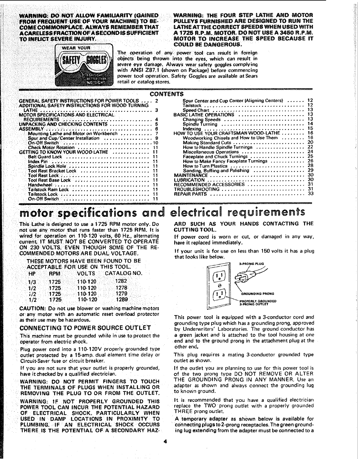
tf your unit is for use on less than t50 volts it has a plug
that looks like below.
_ _3"PROI_G PLUG
_GROUNOfNG P_tONG
PROPERLY GROUNDED
3-PltONG OUTLET
This power tool is equipped with a3-conductor cord and
grounding type plug which hasa grounding prong, approved
by Underwriters' Laboratories, The ground conductor has
a green jacket and is attached to the tool housing at one
end and to the ground prong in the attachment plug at the
other end.
outlet protected by a 15-amp. dual element time deiay or
Circuit-Saver fuse or circuit breaker,
If you are not sure that you r outlet is properly grounded,
have it checked by squalified electrician.
WARNING: DO NOT PERMIT FINGERS TO TOUCH
THE TERMINALS OF PLUGS WHEN INSTALLING OR
REMOVING THE PLUG TO OR FROM THE OUTLET.
WARNING: IF NOT PROPERLY GROUNDED THIS
POWER TOOL CAN INCUR THE POTENTIAL HAZARD
OF ELECTRICAL SHOCK. PARTICULARLY WHEN
USED IN DAMP LOCATIONS IN PROXIMITY TO
PLUMBING. IF AN ELECTRICAL SHOCK OCCURS
THERE IS THE POTENTIAL OF A SECONDARY HAZ-
This plug requires a mating 3-conductor grounded type
outlet as shown.
If the outlet you are planning to use for this power tool is
of the two prong type DO NOT REMOVE OR ALTER
THE GROUNDING PRONG IN ANY MANNER. Use an
adapter as shown and always connect the groundir_g lug
to known ground.
It is recommended that you have a qualified electrician
replace the TWO prong outlet with a properJy grounded
THRE_E prong Outlet.
Atemporary adapter as shown below is available for
connecting plugs to 2-prong receptacles. The green ground-
ing lug extending from the adapter must be connected to a
permanentgroundsuchasto apropertygroundedoutlet
box.
Atemporaryadapteras illustrated is available for connecting
plugs to 2 -pro ng receptecles, The temporary adapter shouId
be used only until a properly grounded outlet can be
installed byaqualified electrician,
GROUNDING LUG
i _ MAKE SURE THIS IS
3-PRONG _'_ [-._-_-_-_--CONNECTED TO A
NowNGROUND
_,_-._ _N_ L_ Jt_'_- 2-PRONG
,_,_ /_'-_J_ RECEPTACLE
ADAPTER
NOTE: The adapter illustrated is for use only if you already
have a properly grounded 2-prong receptacle.
The use of any extension cord will cause some loss of
power. To keep this to a minimum and to prevent over-
heating and motor burn-out, use the table below to deter-
i, !l,i , _1
assembly procedure
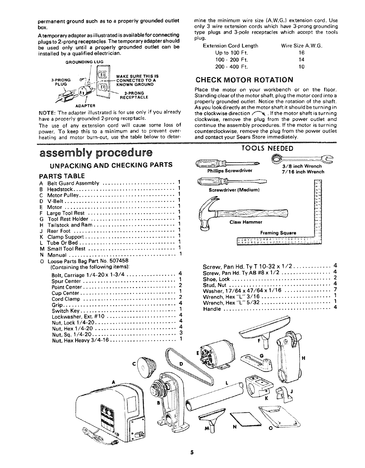
UNPACKING AND CHECKING PARTS
PARTS TABLE
ABelt Guard Assembly ......................... 1
B Headstock ................................... 1
C Motor Pulley ................................. 1
D V-Belt ...................................... 1
E Motor ...................................... 1
F Large Toot Rest .............................. !
G Tool Rest Holder ............................. 1
H Tailstock and Ram ............................ 1
J Rear Foot ................................... 1
K Clamp Support ............................... 1
L Tube Or Bed ................................. 1
M Small Tool Rest .............................. 1
N Manual ..................................... 1
0 Loose Parts Bag Part No. 507458
(Containing the following items):
Bolt, Carriage 1/4-20x 1-3/4 ................. 4
Spur Center ................................ 1
Point Center ................................ 2
Cup Center ................................. I
Cord Clamp ................................ 2
Grip ....................................... 4
Switch Key ................................. 1
Lookwasher, Ext, #10 ........................ 4
Nut, Lock !/4-20 ............................ 4
Nut, Hex 1/4-20 ............................ 4
Nut, Sq. 1/4-20 ............................. 3
Nut, Hex Heavy 3/4-16 ....................... 1
mine the minimum wire size (A,W.G.} extension cord, Use
only 3 wire extension cords which have 3-prong grounding
type plugs and 3-pole receptacles which accept the tools
plug,
Extension Cord Length Wire Size A.W.G.
Up to 100 Ft. t6
t00- 200 Ft. 14
200- 400 Ft. 10
CHECK MOTOR ROTATION
Place the motor on your workbench or on the floor.
Standing clear of the motor shaft, plug the motor cord into a
properly grounded outlet. Notice the rotation of the shaft,
As you look directly at the motor shaft it should be turning in
the clockwise direction _ . If the motor shaft is turning
clockwise, remove the plug from the power outlet and
continue the assembly procedures, If the motor is turning
counterclockwise, remove the plug from the power outlet
and contact your Sears Store immediately.
!, !,,,,i , , ...... •.....
TOOLS NEEDED
Phillips Screwdriver
Screwdriver (Medium)
Framing Square
3/8 inch Wrench
7/16 inch Wrench
Screw, Pan Hd. Ty T 10-32 x !/2 ............. 4
Screw, Pan Hd. Ty AB #8 x 1/2 ................. 4
Shoe, Lock .................................. 2
Stud, Nut ................................... 4
Washer, 17/64 x 47/64 x 1/16 ................ 7
Wrench, Hex "L'" 3/16 ........................ 1
Wrench, Hex "'L" 5/32 ........................ 1
Handle ..................................... 4
A
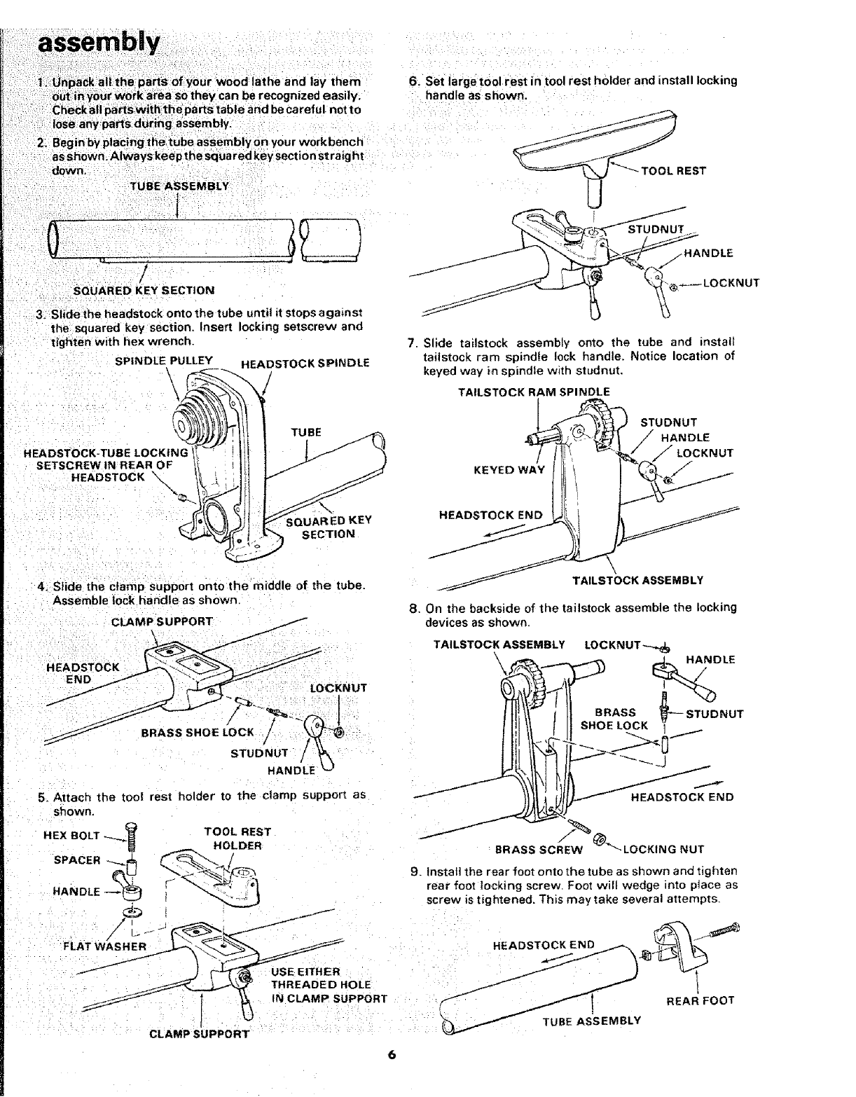
assembly
1. UnpaCk all the part_ of your wood lathe and lay them
0ut in your work area so they can be recognized easily.
Checkall partswith the parts table and be careful not to
"ilose any parts during assembly.
2_ Begin by placing thetUbe assembly on your workbench
as shown. Always keep the squa red key section straig ht
down.
TUBE ASSEMBLY
l
!
/
SQUARED KEY SECTION
.3. Slide the headstock onto the tube until it stops against
the squared key section, Insert locking setscrew and
tighten with hex wrench.
SPINDLE PULLEY
t
TUBE
HEADSTOCK-TUBE LOCKING
SETSCREW tN REAR OF
HEADSTOCK X
HEADSTOCK SPINDLE
_ED KEY
SECTION
4. Slide the clamp support onto the middle of the tube.
Assemble lock handle as shown.
6. Set large tool rest in tool rest holder and install locking
handle as shown.
REST
Slide tailstock assembly onto the tube and install
tailstock ram spindle lock handle. Notice location of
keyed way i_ spindle with studnut,
TAILSTOCK RAM SPINDLE
KEYED
HEADSTOCK END _
STUDNUT
HANDLE
/LOCKNUT
TAILSTOCK ASSEMBLY
8. On the backside of the tailstock asse ruble the locking
devices as shown.
5. Attach the tool rest bolder to the clamp supporl as
shown,
HEX BOLT _.__ TOOL REST
HOLDER
sPACE"
HANDLE _% : "_'_-2
LATWASHER @"a
"--..
_THREADED HOLE
_ I _ IN CLAMP SUPPORT
CLAMP SUPPORT
TAILSTOCK ASSEMBLY LOCKNUT_
_._... ,.,....%% ,._ HANDLE
lllill ts.o2?0CKV---STUONOT
t!!. IIYI f- -----J
ND
BRASS SCREW @"_'-LOCKING NUT
9. Instal] the rear foot onto the tube as shown and tighten
rear foot to,cking screw, Foot wilt wedge into ptace as
screw is tightened. This may take several attempts,
HEADSTOCK END
IREAR FOOT
TUBE ASSEMBLY
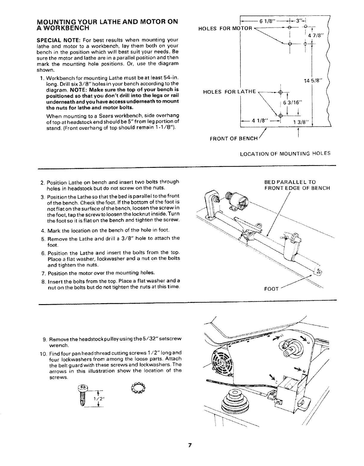
MOUNTING YOUR LATHE AND MOTOR ON
A WORKBENCH
SPECIAL NOTE: For best results when mounting your
lathe and motor to aworkbench, lay them both on your
bench in the position which will best suit your needs. Be
sure the motor and lathe are in a parallel position andthen
mark the mounting hole positions. Or, use the diagram
shown.
1. Workbench for mounting Lathe must be at least 54-in.
long. Drill six 3/8" holes in your bench according to the
diagram, NOTE: Make sure the top of your bench is
positioned so that you don't drill into the legs or rail
underneath and you have access underneath to mount
the nuts for lathe and motor bolts.
When mounting to a Sears workbench, side overhang
of top at headstock end should be 5" from leg portion of
stand. (Front overhang of top should remain 1-1/8").
6 1t8' ----+--, 3'_
HOLES FOR MOTOR i 4f7/8 '"
14 5/8"
HOLES FOR LATHE,
63/16"
4 118" ---i 1 3/8"
/,
FRONT OF BENCH E
LOCATION OF MOUNTING HOLES
2. Position Lathe on bench and insert two bo_ts through
holes in headstock but do not screw on the nuts.
3, Position the Lathe so that the bed is paralleltothe front
of the bench. Check the foot, if the bottom of the foot is
not fiat on the surface of the bench, loosen the screw in
the foot, tap the screw to loosen the Iocknut inside. Turn
the foot so it is flat on the bench and tighten the screw,
4, Mark the location on the bench of the hole in foot.
5, Remove the Lathe and drill a 3/8" hole to attach the
foot.
6. Position the Lathe and insert the bolts from the top,
Place aflat washer, Iockwasher and anut on the bolts
and tighten the nuts.
7. Position the motor over the mounting holes.
8. Insert the bolts from the top. Place a flat washer and a
nut on the bolts but do not tighten the nuts at this time.
BED PARALLEL TO
FRONT EDGE OF BENCH
FOOT
9, Removethe headstockpulleyusingtheS/32"setscrew
wrench.
10, Find four pan head thread cutting screws 1/2" tong and
four Iockwashers from among the loose parts. Attach
the bett guard with these screws and Iockwashers_ The
arrows in this illustration show the location of the
screws.
/
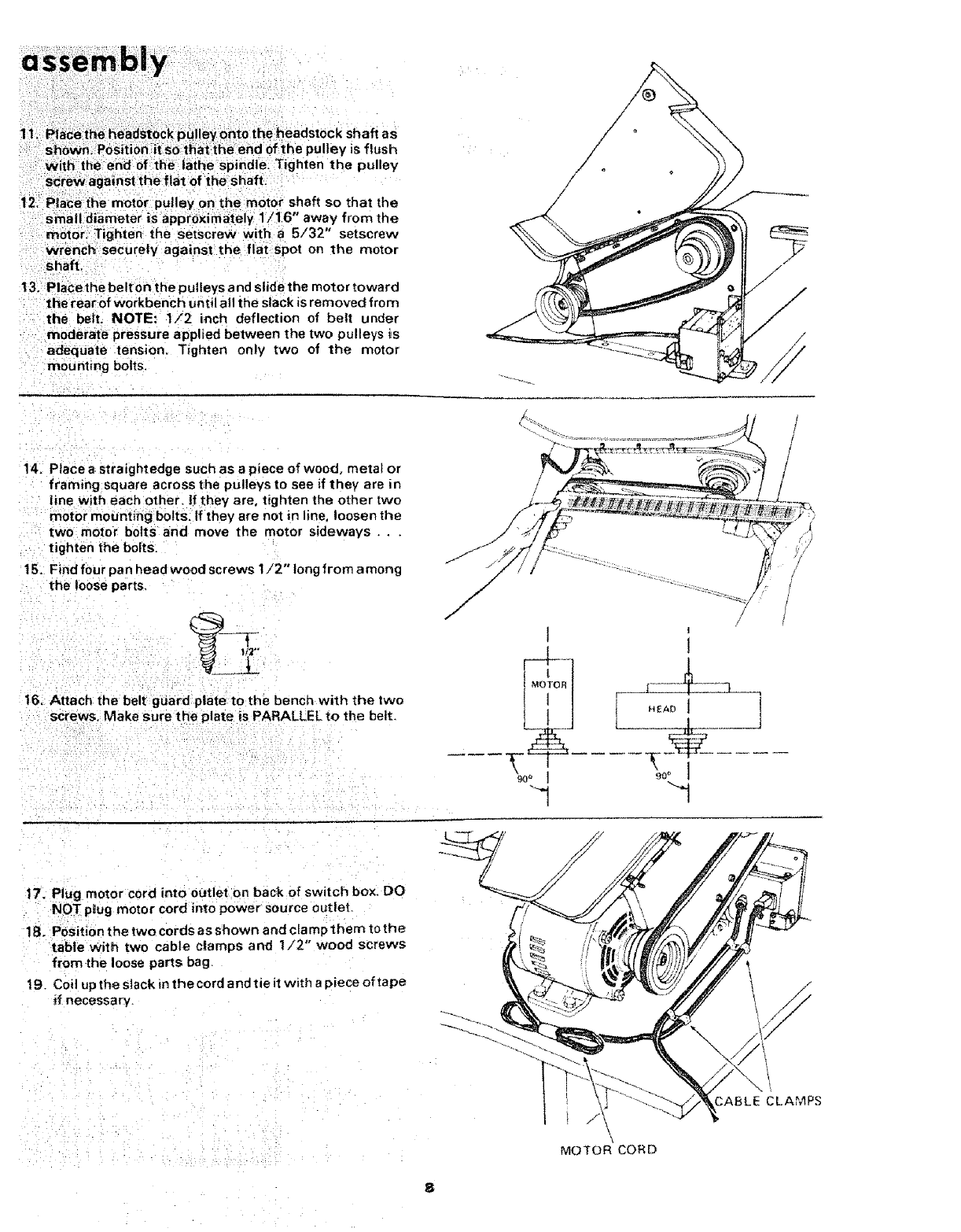
With the end of the la{he spindle: Tighten the pulley
screw against the flat:of theshaft
12, P|ace the motor pulley on the motor shaft so that the
small diameter is approximately 1/16 away from the
motor. Tighten the setscrew with a 5/32" setscrew
wrench securety against the flat spot on the motor
shaft.
t3. Place the belt on the pulleys and slide the motor toward
the rear of workbench until all the slack is removed from
the belt. NOTE: 1/2 inch deflection of belt under
moderate pressure applied between the two pulleys is
adequate tension. Tighten only two of the motor
mounting bolts.
14. Place astraightedge such as apiece of wood, metal or
framing square across the pulleys to see if they are in
line with each other, tf they are, tighten the other two
motor mounting bolts. If they are not in line, loosen the
two motor bolts and move the motor sideways .
tighten the boJts.
15. Find four pan head wood screws t/2" long from a mong
the loose parts
16, Attach the belt guard plate to the bench with the two
screws. Make sure the plate is PARALLEL to the belt.
17. Plug motor cord into outlet o n back of switch box. DO
NOT pJ4ugmotor cord into power source outlet
18. Position the twocordsasshown andclamp themtothe
table with two cable clamps and 1/2" wood screws
from the loose parts bag.
t9. Coil upthe stack in the cord and tie it with a piece of tape
if necessary.
CABLE CLAMPS
MOTOR CORD
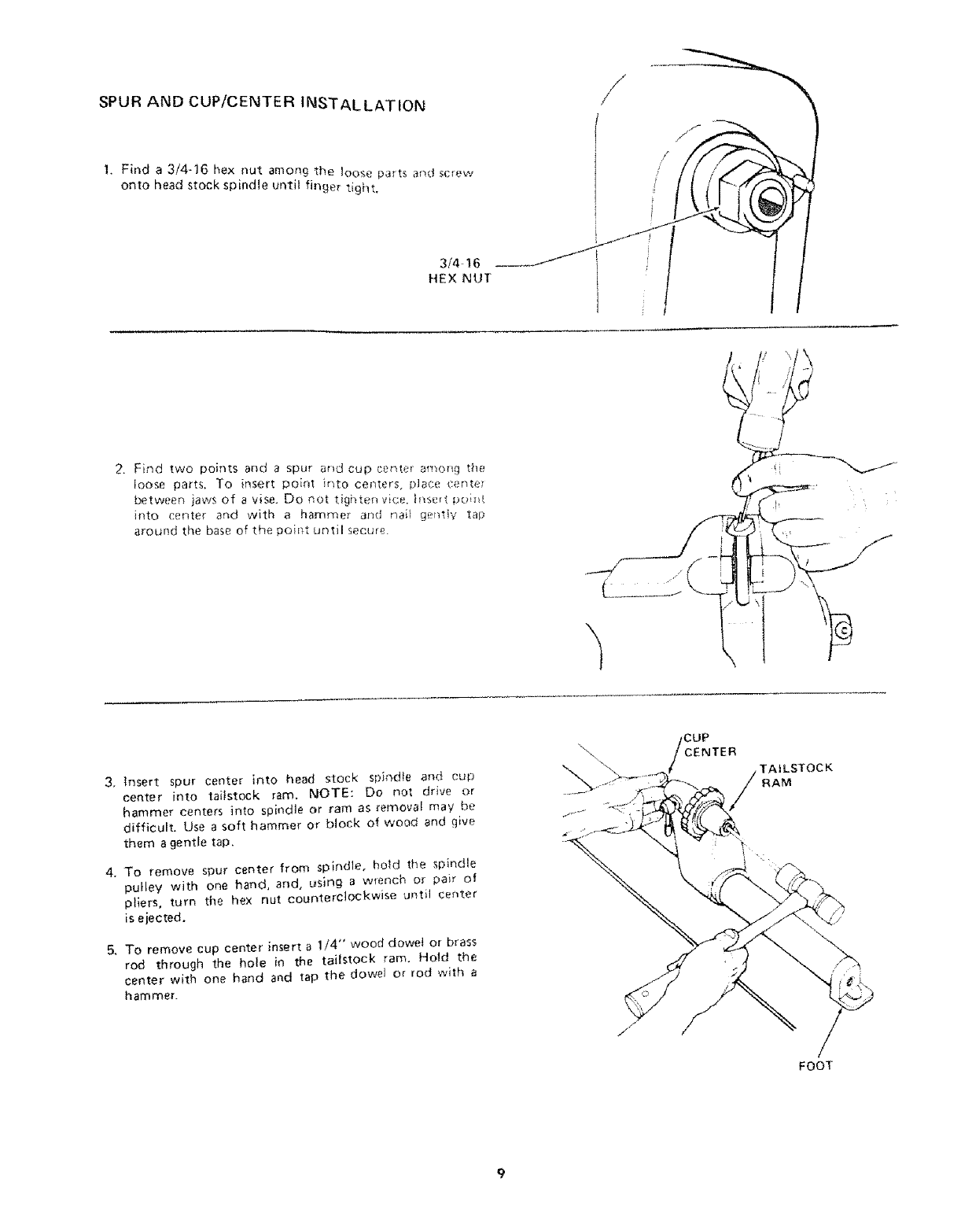
SPUR AND CUP/CENTER 1NSTALLATIOt_
1, Find a 3/4-16 hex nut among the loose parts and scr(_w
onto head stock spindle until finger tight,
3/4 16
HEX NUT
/
i!. |
2. Find two points and a spur ahd cup ct.m_er amo_g the
loose parts. To insert poir_t ir_to cer_ters, _)Jace cente_
between jaws of a vise. Do not ti£hte[_vice h_seq p[_i_
into center and with a hammer and r_ai_ ger_tly tap
around the base of the poh_t until secure
J
f
3, Insert spur center into head stock spir_dle and cup
center into tai;stock ram. NOTE: Do not drive or
hammer centers into spindte or ram as removal may be
difficult, Use a soft hammer or block of wood and give
them agentle tap,
4. To remove spur center from spindle, hen the spindle
pulley with one hand, and, using a wrench or pair of
pliers, turn the hex nut counterclockwise until center
is ejected.
& To remove cup center insert a 1/4" wood dowe_ or brass
rod through the hole in the tailstock ram. Ho{d the
center with one hand and tap the dowet or rod with a
hammer.
\CENTER
TAILSTOCK
RAM
FOOT
assemblly
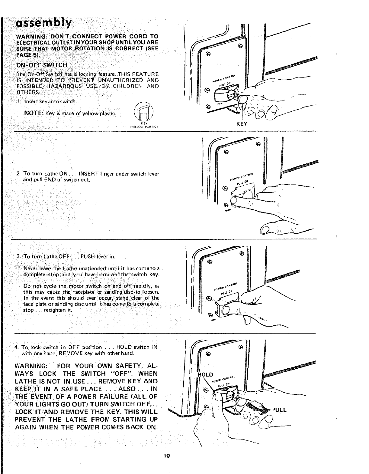
WARNING:OONT CONNECTPOWERCOROTO
ON-OFF SWITCH
The On-Off Switch has a locking feature. THIS FEATURE
IS INTENDED TO PREVENT UNAUTHORIZED AND
POSSIBLE =HAZARDOUS USE BY CHILDREN AND
OTHERS.
1, Insert key into switch.
NOTE: Key is made of yellow _lastic. _1;
KEY
(YELtOW _AST It1
2. To turn Lathe ON,.. INSERT finger under switch lever
and pull END of switch out.
J
KEY
3.: To turn Lathe OFF... PUSH lever in,
Never leave the Lathe unattended until it has come to a
complete stop ant you have removed the switch key.
Do net cycle the motor switch on and off rapidly, as
this may cause the faceplate or sanding disc to loosen.
In the event this should ever occur, stand clear of the
face plate or sanding d_sc until it has come to acomplete
stop, ,. retignten it.
4. To lock switch in OFF position ... HOLD switch IN
with one hand, REMOVE key with other hand.
WARNING: FOR YOUR OWN SAFETY, AL-
WAYS LOCK THE SWITCH "OFF". WHEN
LATHE IS NOT IN USE ... REMOVE KEY AND
KEEP IT IN A SAFE PLACE .ALSO. IN
THE EVENT OF A POWER FAI'LURE (ALL'OF
YOUR LIGHTS GO OUT) TURN SWITCH OFF,,.
LOCK IT AND REMOVE THE KEY. THiS WILL
PREVENT THE LATHE FROM STARTING UP
AGAIN WHEN THE POWER COMES BACK ON.
Io
_OLD
I
I
\\
PULL
ROTATION
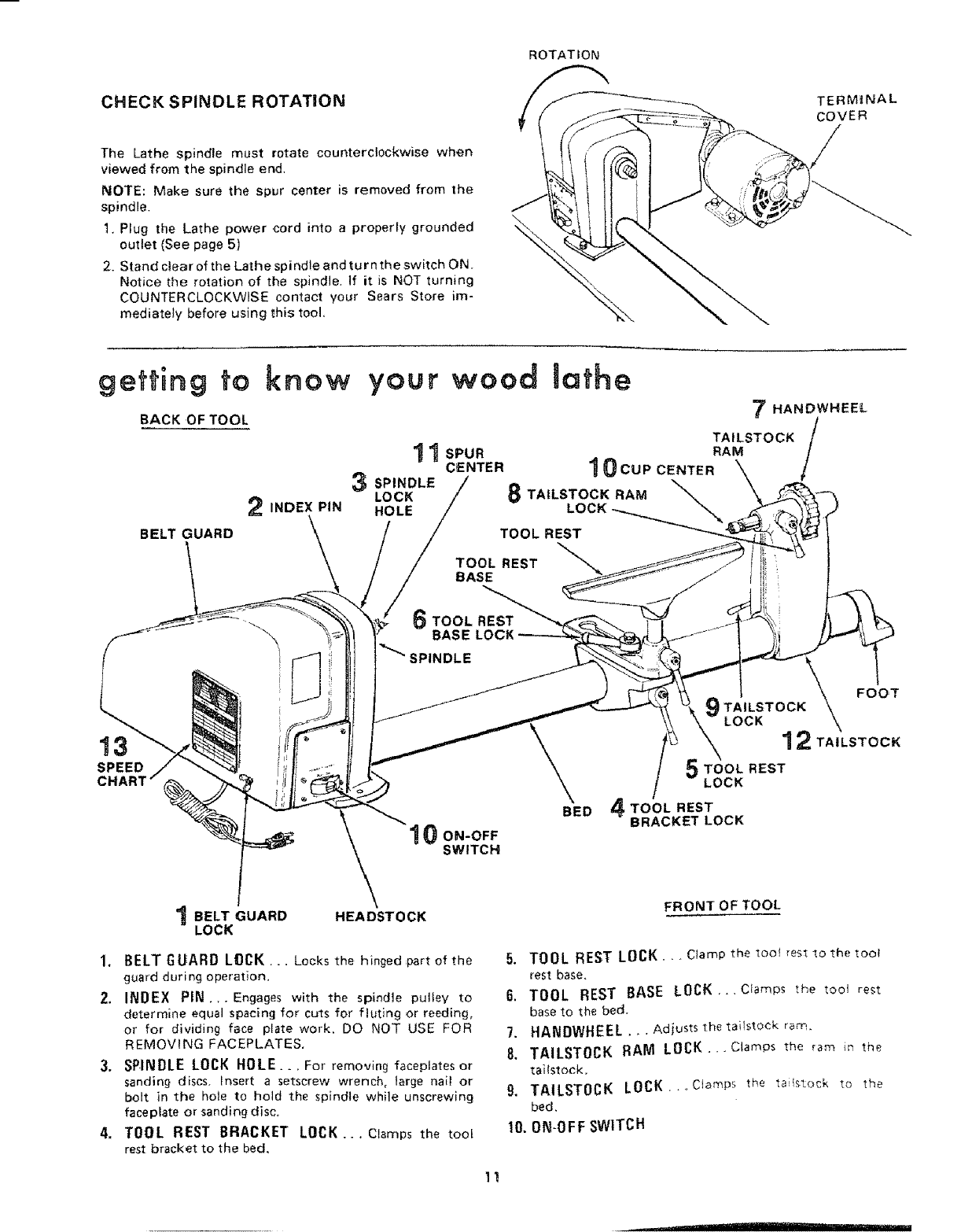
CHECK SPINDLE ROTATION
The Lathe spindle must rotate counterclockwise when
viewed from the spindle end,
NOTE: Make sure the spur center is removed from the
spindle.
1. Plug the Lathe power ,cord into a properly grounded
outlet (See page 5)
2. Stand clear of the Lathe spindle and tur n the switch ON.
Notice the rotation of the spindle. If it is NOT turning
COUNTERCLOCKWISE contact your Sears Store im-
mediately before using this tool,
TERMINAL
coVER
getting to know
BACK OF TOOL
BELT GUARD
2INDEX PIN
your b'VO Od
11 spu.
CENTER
3 SPINDLE
LOCK
HOLE
lathe
7HANDWHEEL
TAILSTOCKRAM /
10 CUP CENTER
8 TAILSTOCK RAM
TOOL REST
TOOL REST _"_
BASE
TOOL REST
BASE LO¢
SPINDLE
!3
SPEED
1BELT GUARD
LOCK
1 0 ON-OFF
SWITCH
HEADSTOCK
I. BELT GUARD LOCK... Locks the hinged part of the
guard during operation.
2. INDEX PIN.,. Engages with the spindle pufley to
determine equal spacing for cuts for fluting or reeding,
or for dividing face plate work. DO NOT USE FOR
REMOVING FACEPLATES,
3. SPINDLE LOCK HOLE.., For removing faceplates or
sanding discs, insert a setscrew wrench, large na_I or
bolt in the hole to hold the spindle while unscrewing
faeep_ate or sanding disc,
4. TOOL REST BRACKET LOCK._. Clamps the tool
rest bracket to the bed,
\BED
FOOT
)TAILSTOCK
LOCK 12 TA,LSTOCK
TOOL REST
LOCK
4TOOL REST
BRACKET LOCK
FRONT OF TOOL
5. TOOL REST LOCK.., Clamp the too_ rest to the tOOl
rest base.
6. TOOL REST BASE LOCK... Clamps the tool rest
base to the bed.
7. HANDWHEEL • . . Adjusts the tailstock ram.
8. TAILSTOCK RAM LOCK,.. Clamps the ram in the
taiistock,
9, TAILSTOCK LOCK.,-CIamPs the tailstock to the
bed,
10. 0N-0FF SWITCH
11
,, °_--=1!--= ......... i
i :gethng to know your wood mafhe
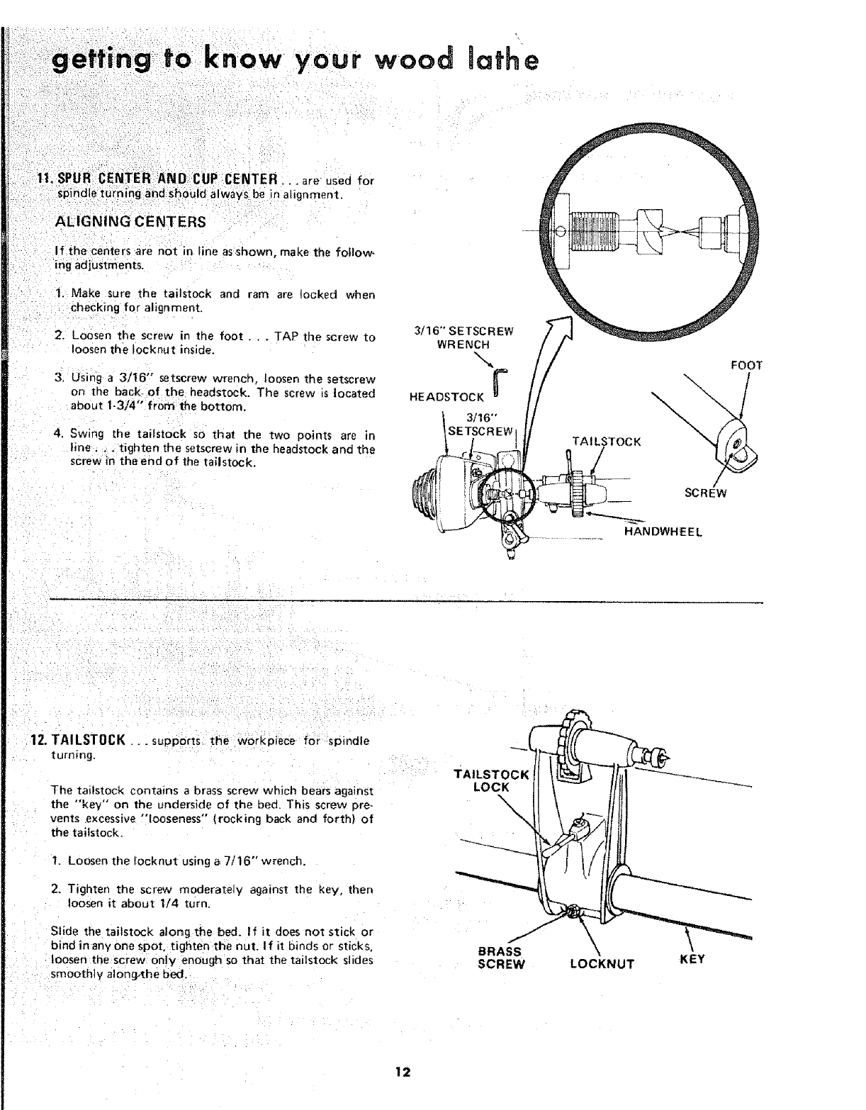
1|. SPUR CENTER AND CUP CENTER_.. are usea for
sPi ndle turn ing and should a iway s be in alignment.
ALIGNING CENTERS
If the centers are not in line as shown, make the follow
ing adjustments.
1. Make sure the tailstock and ram are locked when
checking for alignment.
2. Loosen the screw in the foot. _ TAP the screw to
loosen the tocknut inside.
3, Using a 3116" setscrew wrench, loosen the setscrew
on the back of the headstock. The screw is located
about 1-3/4 "° from the bottom.
4. Swing the tailstock so that the two points are Jn
line. ,. tighten the setscrew in the headstock and the
screw in the end Df the tailstook.
3/16" SETSCREW
WRENCH
HEADSTOCK F
3116"
SETSCREW 1
FOOT
TAI LSTOCK _
_ANDWH_ EW
12. TAILSTOCK _ .supports the workpiece for spindle
turning.
The tailstock contains a brass screw which bears against
the "key" on the underside of the bed. This screw Dre_
vents excessive "looseness" (rocking back and forth} of
the tailstock.
t, Loosen the locknut using a 7/t6" wrench.
2. Tighten the screw moderately against the key, then
loosen it about 114 turn.
Slide the tai}stock atong the bed. If it does not stick or
bind in any one spot, tighten the nut. I f it binds or sticks.
loosen the screw only enough so that the tailstock slides
smoothly along,the bed.
BRASS ',
SCREW LOCKNUT KEY
12
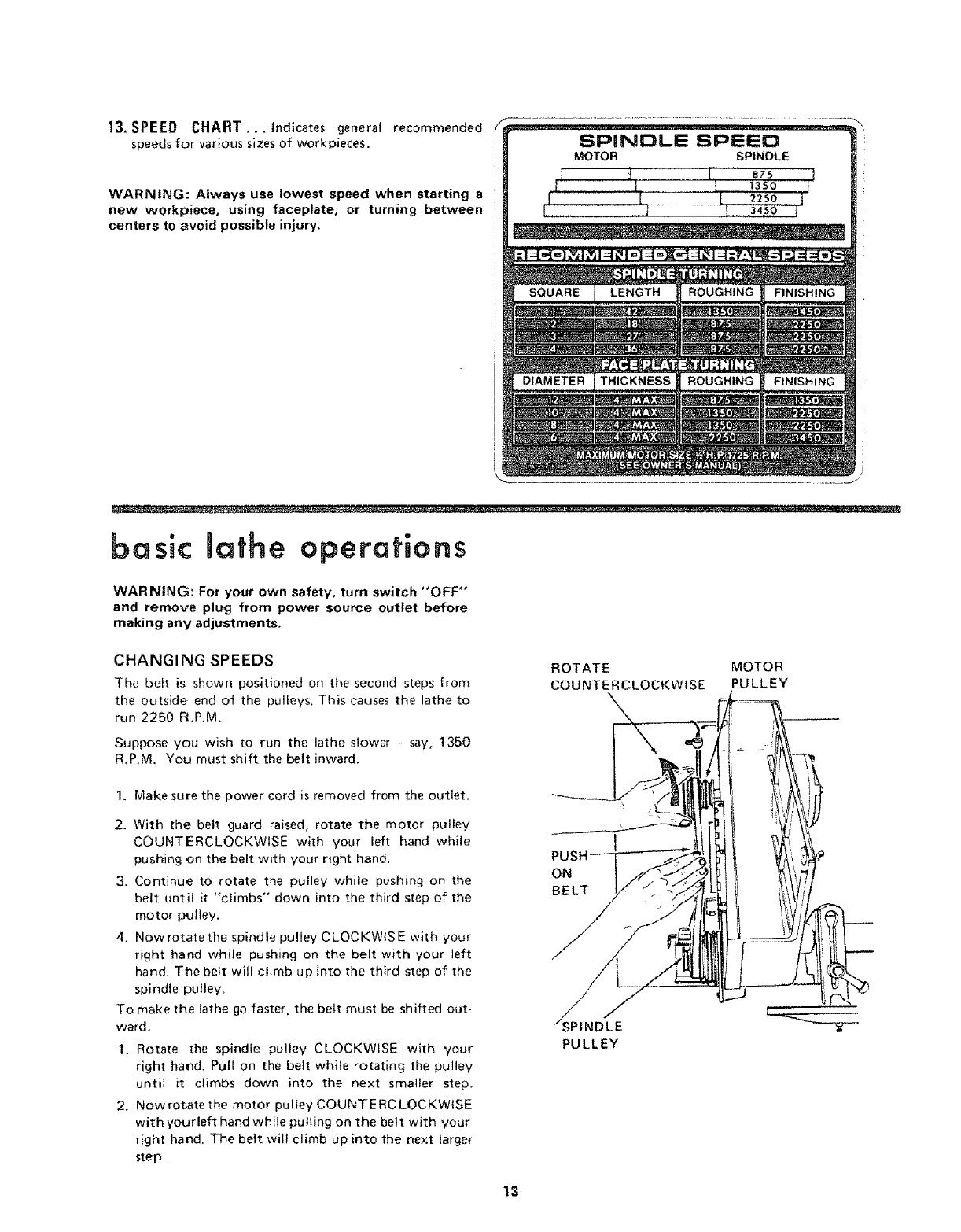
13. SPEED CHART ,..indicates general recommended
speeds for various sizes of workpieces.
WARNING: Always use lowest speed when starting a
new workpiece, using faeeplate, or turning between
centers to avoid possible injury.
SPINDLE SPEED
MOTOR SP|NDLE
iJ 'ti -- {:..... .....J
basic lathe operations
WARNING: For your own safety, turn switch "OFF"
and remove plug from power source outlet before
making any adjustments.
CHANGI NG SPEEDS
The belt is shown positioned on the second steps from
the outside end of the pulleys, This causes the lathe to
run 2250 R.P.M.
Suppose you wish to run the lathe slower _ say, 1350
R.P,M, You must shift the belt inward.
ROTATE MOTOR
COUNTERCLOCKWISE PULLEY
1. Make sure the power cord is removed from the outlet,
2, With the belt guard raised, rotate the motor pulley
COUNTERCLOCKWISE with your left hand while
pushing on the belt with your right hand,
3. Continue to rotate the pulley while pushing on the
belt until it "climbs" down into the third step of the
motor pulley.
4. Now rotate the spindle pulley C LOC KWtS E with your
right hand while pushing on the belt with your left
hand. The belt will climb up into the third step of the
spindle pulley,
To make the lathe go faster, the belt must be shifted out-
ward.
1, Rotate the spindle pulley CLOCKWISE with your
right hand, Pull on the belt while rotating the pulley
until it climbs down into the next smaller step.
2, Nowrotate the motor pulley COUNTERCLOCKWISE
with yourleft hand while pulling on the belt with your
right hand. The beit will climb up into the next larger
step.
ON
BELT
SPINDLE
PULLEY
13
basic lathe operations
If you have never done any amount of wood turn ng, we
suggest that you practice using the various wood turning
tools. Start with=a small spindle turning.
Be sure to study the "HOWTO" section of this manual, It
explains and illustrates thecorreet use ofthe turnings tools,
the positioning of the tool rest and other information to help
you gain experience.
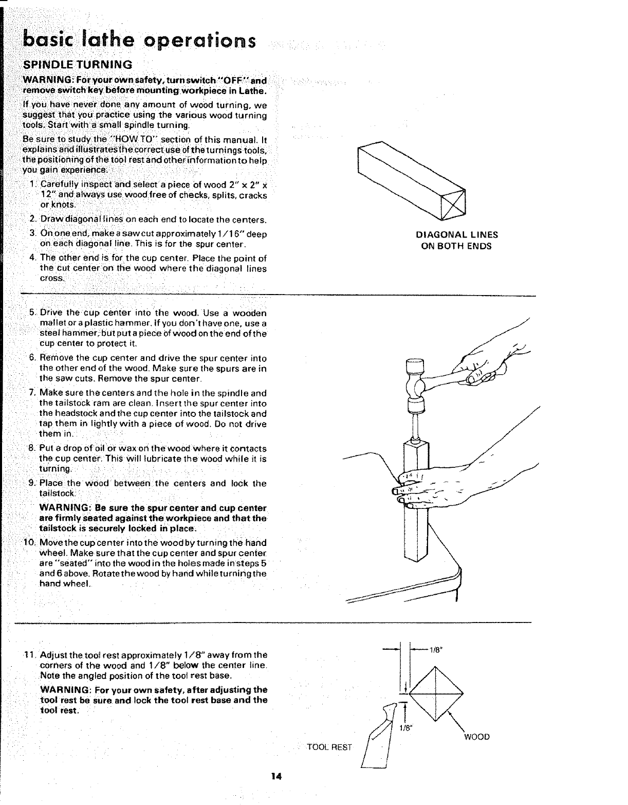
1, Carefully inspect and select a piece of wood 2" x 2" x
12" and always use wood free of checks, splits, cracks
or knots.
2, Draw diagonal lines on each end to locate the centers
3. On oneend, makeasaw cut approximately 1/16" deep
on each diagonal line. This is for the spur center.
4 The other endis for the cup center. Place the point of
the cut center on the wood where the diagonal lines
cross,
DIAGONAL LINES
ON BOTH ENDS
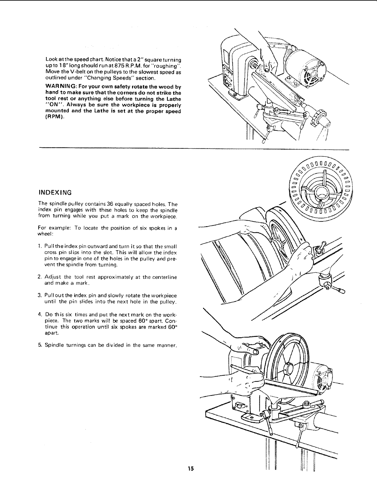
5. Drive the cup center into the wood. Use a wooden
mallet or a plastic hammer, if you don't h ave one, use a
steel ha mmero but put a piece of wood on the end of the
cup center to protect it.
6. Remove the cup center and drive the spur center into
the other end of the wood. Make sure the spurs are in
the saw cuts, Remove the spur center.
7. Make sure the centers and the hole in the spindle and
the tailstock ram are clean, insert the spur center rote
the headstock and the cup center into the tailstock and
tap them in lightly with a piece of wood, Do not drive
them in.
8. Put adrop of oil or wax on the wood where it contacts
the cup center. This witl lubricate the wood while it is
turning,
9. Place the wood between the centers and iock the
tailstock:
WARNING: Be sure the spur center and cup center
are firmlyseated against the workpiece and thatthe
tailstock is securely locked in place.
i0, M0vethe cup center intothe wood byturnmg the hand
wheel. Make sure that the cup center and spur center
are "seated" into the wood in the holes made insteps 5
and 6 above. Rotate the wood by hand while turning the
hand wheel.
t 1. Adjust the tool rest approxirnately 1/8" away fro m the
corners of the wood and 1/8" below the center line.
Note the angled position of the toot rest base.
WARNING: For your own safety, after adjusting the
tool rest be sure and lock the toot rest base and the
tool rest.
TOOL REST
14
Lookatthespeedchart.Noticethata2"squareturning
upto18"longshouldrunat875R.P.M.for"roughing".
MovetheV-beltonthepulleystotheslowestspeedas
outlinedunder"'Changing Speeds" section,
WARNING: For your own safety rotate the wood by
hand to make sure that the corners do not strike the
tool rest or anything else before turning the Lathe
"'ON", Always be sure the workpiece is properly
mounted and the Lathe is set at the proper speed
(RPM).
INDEXING
The spindle pulley contains 36 equalty spaced ho_es. The
index pin engages with these holes to keep the spindle
from turning while you put a mark on the workpiece.
For example: To focate the position of six spokes in a
wheel:
1. Pult the index pin outward and turn it so that the small
cross pin slips into the slot, This will allow the index
pin to engage in one of the holes in the pulley and pre-
vent the spindle from turning_
2, Adjust the tool rest approximately at the centeriine
and make a mark.
3. Pull out the index pin and slowly rotate the workpiece
until the pin slides into the next hole in the pulley.
4. Do th is six times and put the next mark on the work-
piece, The two marks will be spaced 60 ° apart, Con-
tinue this operation until six spokes are marked 60 °
apart.
5, Spindle turnings can be divided in the same manner,
t5
•cratts an wood-Uathe
INGCH|SELs AND HOW TO USE THEN
:PARTING TOOL
iBe_ ch+s+iS ha_e bandies approximately l O-in. t+ongo to
pt-oVide plenty Ofgripand leverage, sharp tools are ess ent ia |
for Clean+ eas+y work buy tools that will take and hold
keen edges
THEORYOF TURNING
CUTTING CHISEL SCRAPING CHISEL
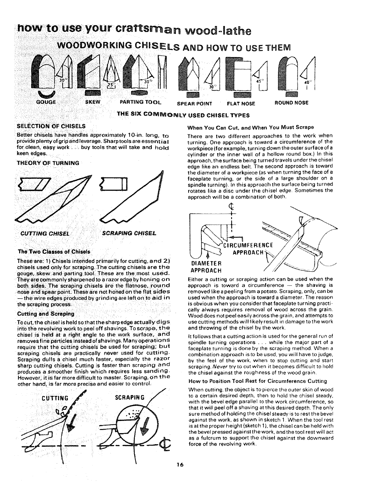
The Two Classes of Chisels
Theseare: 1} Chisels intended primarily for cutting, a nd 2)
chisels used only for scraping: The cutting chisels are the
gouge, :skew and parting tool. These are the most used.
They are com monly sharpened to arazor edge by honing on
both sicles_ The scraping chisels are the flatnose, round
nose and spear point. These are not honed on the flat sides
-- the wire edges produced by grinding are left on to aid in
the scraping process.
To cut, the chisel is held so that the sharp edge actually d_gs
into the revolving work to peel off shavings. To scrape. _he
chisel is held at a right angle to the work surface, and
removes fine particles instead of shavings. Ma ny operations
require that the cutting chisels be used for scraping; bu_
scraping chisels are practically never used for cutting:.
Scraping dulls achisel much faster, especially the razor
sharp cutting chisels. Cutting is faster than scraping and
produces asmoother finish which requires less sanding.
However. it is far more difficult to master. Scraping, on the
other hand. is far more precise a nd easier to control.
___SCR_P_
SPEAR P0tNT FLAT NOSE
USED CHISEL TYPES
ROUND NOSE
When You Can Cut, and When You Must Scrape
There are two different approaches to the work when
turning, One approach is toward acircumference of the
workpiece (fore×ample, turning down the outer surface of a
cylinder or the inner wall of a hollow round box.) in this
approach, the surface being turned travels under the chise_
edge tike an endless belt. The second approach is toward
the diameter of aworkpiece (as when turning the face of a
faceplate turning, or the side of alarge shoulder on a
spindle turning), In this approach the surface being turned
rotates like adisc under the chisel edge, Sometimes the
approach will be a combmat+on of both,
¢
t
!
_---_,vCI RCUMFER ENCE
"-....J/ _ APPROACH_
DIAMETER .... 1t
APPROACH
Either a cutting or scraping action can be used when the
approach =s toward a circumference -.- the shaving is
removed tike a _eeling from apotato_ Scraping, only, can be
used when the approach is toward a diameter, The reason
is obvious when you consider that faceplate turning practi +
cally always req u_res removal of wood across the grain.
Wood does not peel easily across the grain, and attempts to
use cutting methods will likely result in damage to the work
and throwing of the chisei by the work.
it follows that a cutting action is used for the genera_ run of
spindle turning operations , +. while the major part of a
facep_ate turning is done by the scraping method, When a
combination approach is to be used+ you will have to judge,
by me feel of the work. when to stop cutting and start
scraping Never try to cut when it becomes difficult to hold
the chisel against the roughness of the wood grain.
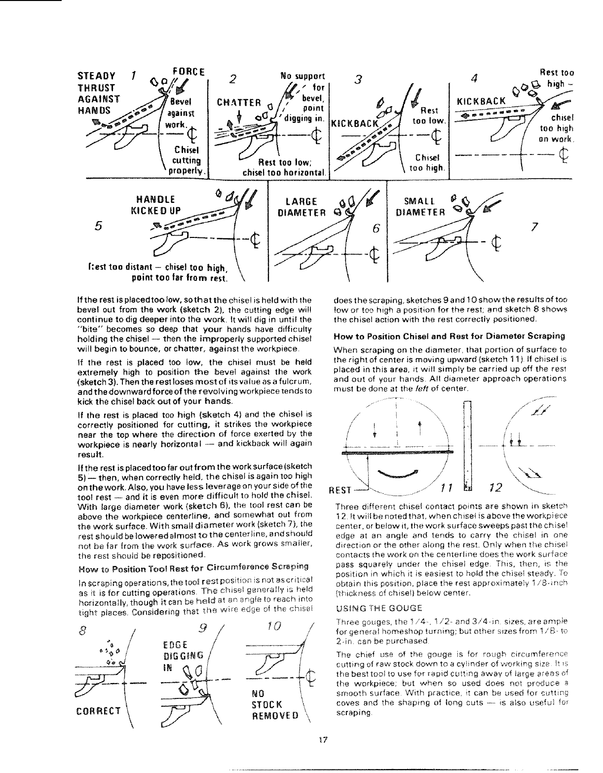
How to Position Tool Rest for Circumference Cutting
When cutting, the object ia to pierce the outer skin of wood
to a ceGa_n desired depth, then to hold the chisel steady,
with the bevel edge paral;et to the work circumference, so
that it will peel off a shaving at this desired depth. The on+y
sure method of holding the chisel steady is to rest the bevel
against the work. as shown in sketch 1. When the toot rest
is at the proper height (sketch t ), the chisel ca n be held with
the bevel pressed against the work, and the tool rest will act
as afulcrum to support the chisel against the downward
force of the revolving work,
"16
STEADY 1(_ 0/F5 RCE
THRUST _,'_
AGAINST /i _Bev_et
HAedDS ain
Jor.._
Chise!
cutting
properly.
2No support
,_j, for
CHATTER G/_ bevel'
•//pofnt
tOO 'digging in.
Rest too low;
chisel too horizontal.
3
_!_Rest
4Rest too
_,0_ high-
KICKBACK _
mmw_m _ chisel
/// toohigh
HANDLE (_
KICKED U_
Rest too distant -chisel too high,
point too far from rest.
7
If the rest is placed too low, so that the chise! is held with the
bevel out from the work (sketch 2}, the cutting edge will
continue to dig deeper into the work. It will dig in until the
"'bite" becomes so deep that your hands have difficulty
holding the chisel -- then the improperly supported chisel
will begin to bounce, or chatter, against the workplace.
If the rest is placed too tow, the chisel must be held
extremely high to position the bevel against the work
(sketch 3). Then the rest loses most of its value as a fulcrum,
and the downward force of the revolving workplace tends to
kick the chisel back out of your hands.
If the rest is placed too high (sketch 4) and the chisel is
correctly positioned for cutting, it strikes the workpiece
near the top where the direction of force exerted by the
workpiece is nearly horizontal -- and kickback will again
result.
If the rest is placed too far out from the work surface (sketch
5}-- then, when correctly heid, the chisel is again too high
on the work. Also, you have less leverage on your side of the
tool rest -- and it is even more difficult to hold the chisel
With large diameter work (sketch 6), the tool rest can be
above the workpiece centertine, and somewhat out from
the work surface. With small d_ameter work (sketch 7), the
rest should be lowered almost to the centeHine, and shoutd
not be far from the work surface. As work grows smafler,
the rest should be repositioned.
How to Position Toot Rest for CircumferenCe Scraping
In scraping operations, the too_ rest posit{on is not as critica!
as it is for cutting operation, s. The chisel generally is held
horizontally, though it can be he_d_ at an _ngfe to reach into
tight places. Considering that the wife edge of the ehisef
8/
CORRECT
9 / yo /
DIGGING //
STOCK \
REMOVE D \\
does the scraping, sketches 9 and 10 show the results of too
!ow or too high a position for the rest; and sketch 8 shows
the chisel action with the rest correctly positioned.
How to Position Chisel and Rest for Diameter Scraping
When scraping on the diameter, that port,on of surface to
the right of center is moving upward (sketch 1 t ) If chisel is
placed in this area, it will simply be carried up off the rest
and out of your hands All diameter approach operations
must be done at the taft of center
.....Ti '"i...."' i ......
/
;.........!, .L .
.................................. i...........
/_
'x,\ _ ///
REST"t .......... .......1 1 12 .__
Throe different chisel contact po*nts are shown in sketch
! 2. it will be noted that, when chise! is above the workpiece
center, or be_ow it, the work surface sweeps past the ch iset
edge at an angle and tends to carry the chisel JR orle
direction or the other along the rest. Orfly when the chisel
contacts the work or_ the centerfine does the work surface
pass squarely under the chisel edge. This, then, is the
position in which it is easiest to hold the chise_ steady. To
obtain this position, place the res_ appr'oximate}y I/8. inch
{thickness o{ chise!) below centel.
USING THE GOUGE
"}"hroe gouges, the t/4. I/2- _nd 3/4-in sizes, are ampie
for general homeshop turning; but ether srzes from I iS- to
2-in can be purchased
The chief use of the gouge is for rough circumference
cutting of raw stock down to a cylinder of working size it ts
the best too_ ,_ouse for r_pid cutting away of _arge a_eas of
the workpiece; but when so used does not produce a
smooth surface With practice, it can be used for cutting
coves and the shaping of _ong cuts ----is also usefui fo_
scraping.
_7
howto use your craftsman wood-lathe
--.... CUTTING EDGE
" ANCEO WRONG CUTTING SCRAPING
I
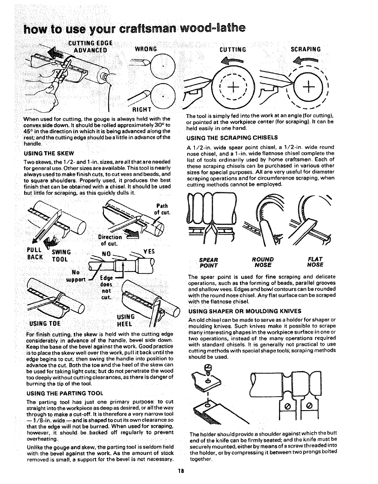
When used for cutting, the gouge is always held with the
convex side down° It should be rolled approximately 30 ° to
45 ° in the direction in which it is being advanced along the
rest; and the cutting edge should be a little in advance of the
handle.
USING THE SKEW
Two skews, the I/2- and 1-in. sizes, are allthat are needed
for general use. Other sizes are available, This tool isnearly
always used to make finish cuts. to cut vees and beads, and
to square shoulders. Properly used, it produces the best
finish that can be obtained with a chisel, It should be used
but little for scraping, as this quickly dulls it.
Path
of cut.
PULL SWING _NO _..__ _....., Y ES
BACK TOOL
I_I.._I I II _
&;o,, not
cut.
USING TOE HEEL /_"
For-finish cutting, the skew is held with the cutting edge
considerably in advance of the handle, bevel side down.
Keep the base of the bevel against the work. Good practice
iSto place the skewwe|t over the work, pull it back until the
edge begins to cut, then swing the handle into position to
advance the cut. Both the toe and the heel of the skew can
be used for taking light cuts; but do not penetrate the wood
too deeply without cutting clearances, asthere is danger of
burning the tip of the tool.
USING THE PARTING TOOL
The parting tool has just one primary purpose: to cuz
stra Jghtinto the workpiece a sdeep as desired, orall the way
through to make a cut-off. It is therefore a very narrow tool
-- 1/8-ir_, wide-- and is shaped to cut its own clearance so
that the edge wil! not be burned. When used for scraping,
however, it should be backed off regularly to prevent
overheating.
Unlike the gouge and skew, the parting tool is seldom held
with the bevel against the work. As the amount of stock
removed is small, a support for the bevel is not necessary.
The tool is simply fed into the work at an angle (for cutting),
or pointed at the workpiece center (for scraping). It can be
held easil_ in one hand.
USING THE SCRAPDNG CHISELS
A1/2-in. wide spear point chisel, a !f2-in. wide round
nose chisel, and a 1 -in. wide flatnose chisel complete the
list of tools ordinarily used by home craftsmen. Each of
these scraping chisels can be purchased in various other
sizes for special purposes. All are very useful for diameter
scraping operations and for circumference scraping, when
cutting methods cannot be employed.
SPEAR ROUND FLAT
POINT NOSE NOSE
The spear point is used for fine scraping and delicate
operations, such as the forming of beads, parellel grooves
and shallow vees. Edges and bowl contours can be rounded
with the round nose chisel. Any flat surface can be scraped
with the flatnoSe chisel.
USING SHAPER OR MOULDING KNIVES
An old chisel ca n be made to serve as a holder for shaper or
moulding knives. Such knives make it possible to scrape
many interesting shapes in the workpiece surface in one o_
two operations, instead of the many operations required
with standard chisels_ It is generally not practical to use
cutting methods with special shapetools; scraping methods
should be used.
f°
The holder should provide a shoulder against which the butt
end of the knife can be firmlyseated; and the knife must be
securely mounted, either by means of ascrew threaded into
the holder, or by compressing it between two prongs bolted
together.
18
Clear, glass-smooth finishes(especially on soft-woods) can
be obtained by using ablock plane set to take afine shaving,
The tool rest should be raised up approximately to the top of
the workpiece -- and the plane should be horizontal, but
turned stightly in the direction of travel so that it will take a
shearing cut, Two tool rests, one in front and the other
behind the work, can be used to advantage in positioning
the plane so as to exactly l imitt he depth of cut (and fin ished
size of the workpiece),
USING WOOD RASPS AND FILES
A wood rasp will remove stock quickly when hetd against
the revolving workpiece. Care should be taken to support
the rasp firmly against the tool rest, however, as it can tear
the hands painfully if caught by a rough edge of the
workpiece and kicked back. The rasp will leave a very rough
finish.
Finer finishes(similar to those produced by scraping) can be
obtained by using files in the same manner. Various shape
files can be used for shaping vees, beads, coves, etc. If
pressed into the wood too hard, however, a file can burn the
workpiece surface. Keep the file clean to keep it cutting
uniformly. Files work best on hardwoods.
HAND POSITIONS
WARNING: Keep firm hold and control of the turning
tool at all times. Avoid awkward hand positions where a
sudden stip could cause ahand to move into the
workpiece.
In handling allof the chisels the handle hand takes a natural
position, being nearer or farther from the end depending
upon the amount of leverage required. The position of the
toot rest hand is a'matter of individual liking; but there are
three genera!ly accepted positions, each best for certain
types of operations.
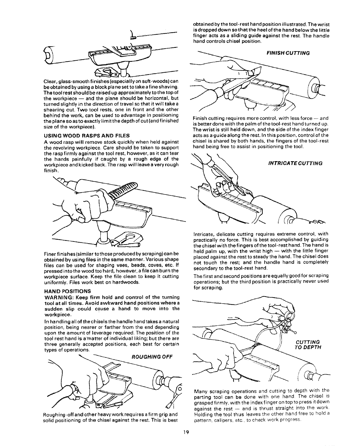
ROUGHING OFF
I
Roughing-offand other heavywork requires a firm grip and
solid positioning of the chisel against the rest. This is best
obtained by the tool-rest hand position illustrated. The wrist
is dropped down sothat the heel of the hand below the tittle
finger acts as a sliding guide against the rest. The handle
hand controls chisel position.
19
FINISH CUTTING
Finish cutting requires more control with less force -- and
is better done with the palm of the tool-rest hand turned up,
The wrist is still held down, and the side of the index finger
acts as agu ide along the rest. In this position, controt of the
chisel is shared by both hands, the fingers of the tool-rest
hand being free to assist in positioning the tool.
IN TRICA TE CUTTING
Intricate, delicate cutting requires extreme control, with
practically no force. This is best accomplished by guiding
the chisel with the fingers of the tool-rest hand. The hand is
held palm up, with the wrist high -- with the little finger
placed against the rest to steady the hand, The chisel does
not touch the rest; and the handle hand is completely
secondary to the tool-rest hand.
The first and second positions are equally good for scraping
operations; but the third position is practically never used
for scraping,
CUTTING
TO DEPTH
Many scraping operations and cutting to depth with the
parting toot can be done with one hand The chiset is
grasped firmly, with the index finger on top to press it dowr_
against the rest -- and is thrust straight into the work
Holding the toot thus leaves the other hand free to hold a
pattern, calipers, etc.. to check work progress
gouge,
\_ H
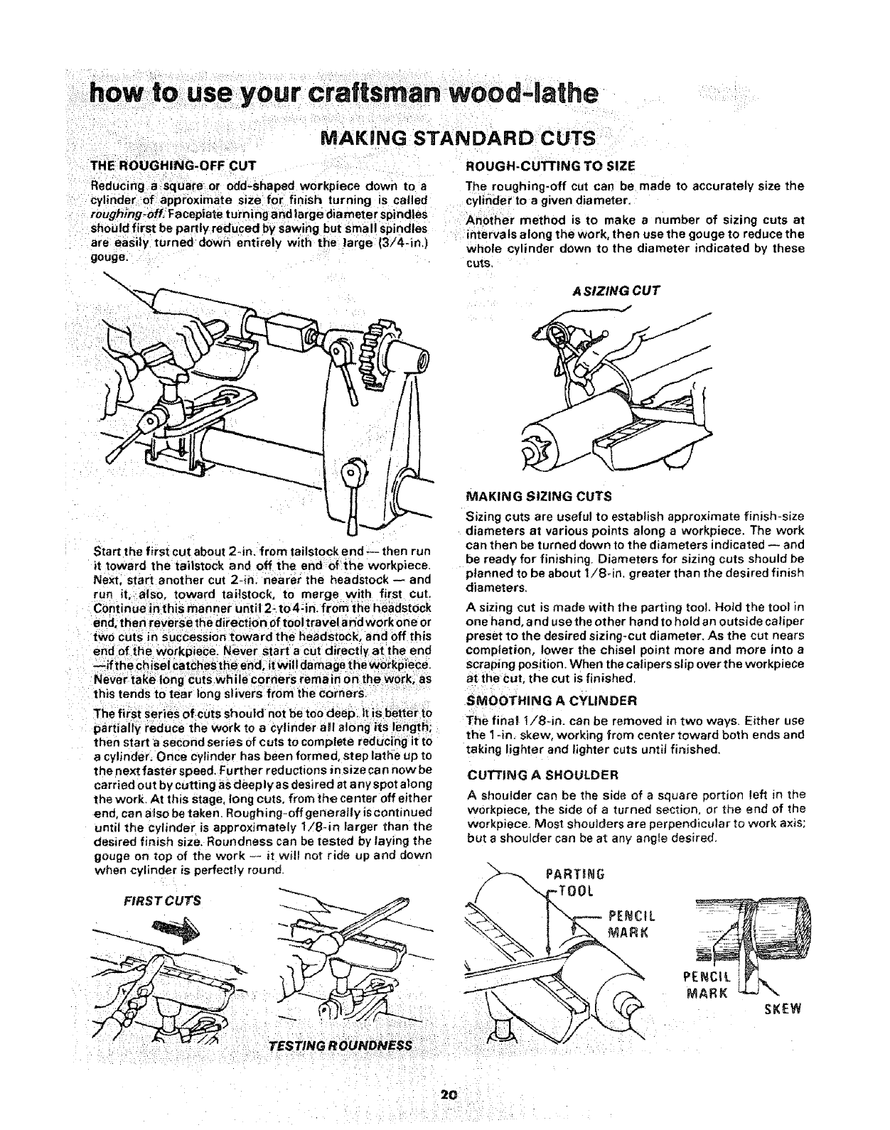
A SIZING CUT
Start the first cut about 2-in, from tailstock end -- then run
it toward the taitstock and off the end of the workpiece,
Next, start another cut 2-in. nearer the headstock -- and
run it also, toward tailstock, to merge with first cut.
Continue in this manner until 2- to4-in, from the headstock
end, then reverse the direction of tool travela nd work one or
two cuts in succession toward the headstock, and off this
end of the workpjece. Never start a cut directly at the end
--if the chisei Catchesthe end, itwill damage the workpiece.
Never take tong cuts while corners remain on the work, as
this tends to tear long slivers from the corners.
The first series of cuts should not be too deep it iS better to
partially reduce the work to a cylinder a(I along its length;
then start a second series of cuts to complete reducing it to
a cylinder. Once cylinder has been formed, step lathe up to
the next faster speed. Further reductions in size ca n now be
carried out by cutting as deeply as desired at any spot along
the work. At this stage, tong cuts, from the center off either
end, can also be taken, Roughing-off generally _scontinued
until the cylinder is approximately 1/8-in larger than the
desired finish size. Roundness can be tested by laying the
gouge on top of the work -- it will not ride up and down
when cylinder is perfectly round_
FtRST CUTS
MAKING SIZING CUTS
Sizing c_Jts are useful to establish approximate finish-size
diameters at various points along a workpiece. The work
can then be turned down to the diameters indicated -- and
be ready for finishing. Diameters for sizing cuts should be
planned to be about 1/8-in. greater than the desired finish
diameters.
Asizing cut is made with the parting tool. Hold the tool in
one hand, and use the other hand to hold an outside caliper
preset to the desired sizing-cut diameter. As the cut nears
completion, lower the chisel point more and more into a
scraping position. When the calipers slip over the workpiece
at the cut, the cut is finished.
SMOOTHING A CYLINDER
The fina! I/8-in. can be removed in two ways. Either use
the I *in. skew, working from center toward both ends and
taking lighter and lighter cuts until finished.
CUTTING A SHOULDER
A shoulder can be the side of asquare portion left in the
workpiece, the side of a turned section, or tr}e end of the
workpiece. Most shoulders are perpendicular to work axis;
but ashoulder can be at any angle desired.
_TOOL PARTING
PARK _ \
SKEW
20
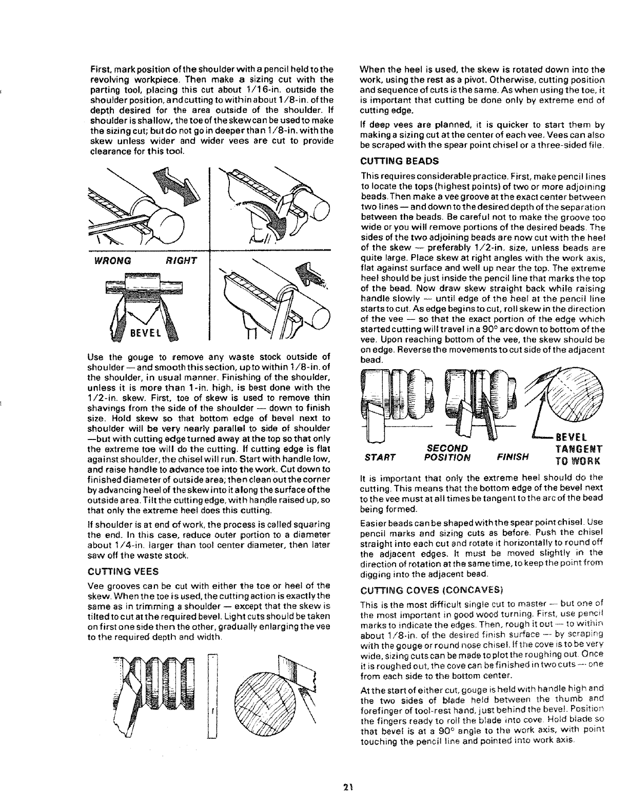
First,mark position of the shoulder with a pencil held tothe
revolving workpiece. Then make a sizing cut with the
parting toolo placing this cut about 1/16-in. outside the
shoulder position, and cutting to within about 1/8-in. of the
depth desired for the area outside of the shoulder. If
shoulder is shallow, the toe of the skew can be used to make
the sizing cut; but do not go _ndeeper than 1/84n. with the
skew unless wider and wider vees are cut to provide
clearance for this tool.
WRONG RIGHT
BEVEL
Use the gouge to remove any waste stock outside of
shoulder -- and smooth this section, up to within t/8-in, of
the shoulder, in usual manner. Finishing of the shoulder,
unless it is more than lqn. high, is best done with the
1/2-in. skew. First, toe of skew is used to remove thin
shavings from the side of the shoulder -- down to finish
size, Hold skew so that bottom edge of bevel next to
shoulder will be very nearly parallel to side of shoulder
--but with cutting edge turned away at the top so that only
the extreme toe will do the cutting. If cutting edge is flat
against shoulder, the chisel will run. Start with handle low,
and raise handle to advance toe into the work. Cut down to
finished diameter of outside area; then cfean out the corner
byadvancing heel of the skew into italong the surface of the
outside area. Tilt the cutting edge, with handle raised up, so
that only the extreme heel does this cutting.
if shoulder is at end of work, the process is ca_ledsquaring
the end. In this case, reduce outer portion to a diameter
about 1/4-in. larger than too! center diameter, then inter
saw off the waste stock,
CUTTING VEES
Vee grooves can be cut with either the toe or heel of the
skew. When the toe is used, the cutting action is exactly the
same as in trimming a shoulder -- except that the skew is
tilted to cut at the required bevel. Light cuts she uid be taken
on first one side then the other, gradually enlarging the vee
to the required depth and width.
When the heel is used, the skew is rotated down into the
work, using the rest as a pivot. Otherwise, cutting position
and sequence of cuts is the same. As when using the toe, it
is important that cutting be done only by extreme end of
cutting edge_
If deep vees are planned, it is quicker to start them by
making a sizing cut at the center of each vee, Vees ca n also
be scraped with the spear point chisel or athree-sided file.
CUTTING BEADS
This requires considerable practice. First, make pencil lines
to locate the tops (highest points) of two or more adjoining
beads. Then make avee groove at the exact center between
two lines-- and down to the desired depth of the separation
between the beads, 8e carefuf not to make the groove too
wide or you will remove portions of the desired beads, The
sides of the two adjoining beads are now cut with the heel
of the skew -- preferably 1/2-in. size, unless beads are
quite large. Place skew at right angles with the work axis,
flat against surface and well up near the top, The extreme
heel should be just inside the pencil line that marks the top
of the bead. Now draw skew straight back while raising
handle slowly -- until edge of the heel at the pencil tine
starts to cut. As edge begins to cut, roll skew in the direction
of the vee -- so that the exact portion of the edge which
started cutting will travel in a 90 ° arc down to bottom of the
vee. Upon reaching bottom of the vee, the skew should be
on edge. Reverse the movements to cut side of the adjacent
bead.
SECOND
START POSITION
BEVEL
TANGENT
FINISH TO WORK
It is important that only the extreme heel should do the
cutting. This means that the bottom edge of the bevel next
to the vee must at all times be tangent to the arc of the bead
being formed.
Easier beads can be shaped with the spear point chisel. Use
pencil marks and sizing cuts as before. Push the chisel
straight into each cut and rotate it horizontally to round off
the adjacent edges, tt must be moved slightly in the
direction of rotation at the same time, to keep the point from
digging into the adjacent bead.
CUTTING COVES (CONCAVES)
This is the most difficult single cut to master ---- but or_e of
the most important in good wood turning. First, use pencil
marks to indicate the edges. Then, rough it out -.- to withis
about 1/8-in. of the desired finish surface --- by scrapir_g
with the gouge or round nose chisel. _f the cove is to be very
wide, sizing cuts can be made to plot the roughing out. Once
it is roughed out, the cove can be finished in two cuts----.- one
from each side to the bottom center.
At the start of either cut, gouge is held with handie high and
the two sides of blade held between the thumb and
forefinger of tool-rest hand, just behind the bevel_ Positio#
the fingers ready to roli the blade into cove. Hoid blade so
that bevel is at a 90 ° angle to the work axis, with point
touching the pencil line and pointed into work axis.
2_
SWING
TOOL
CUTTING
BEADS
wood-lathe
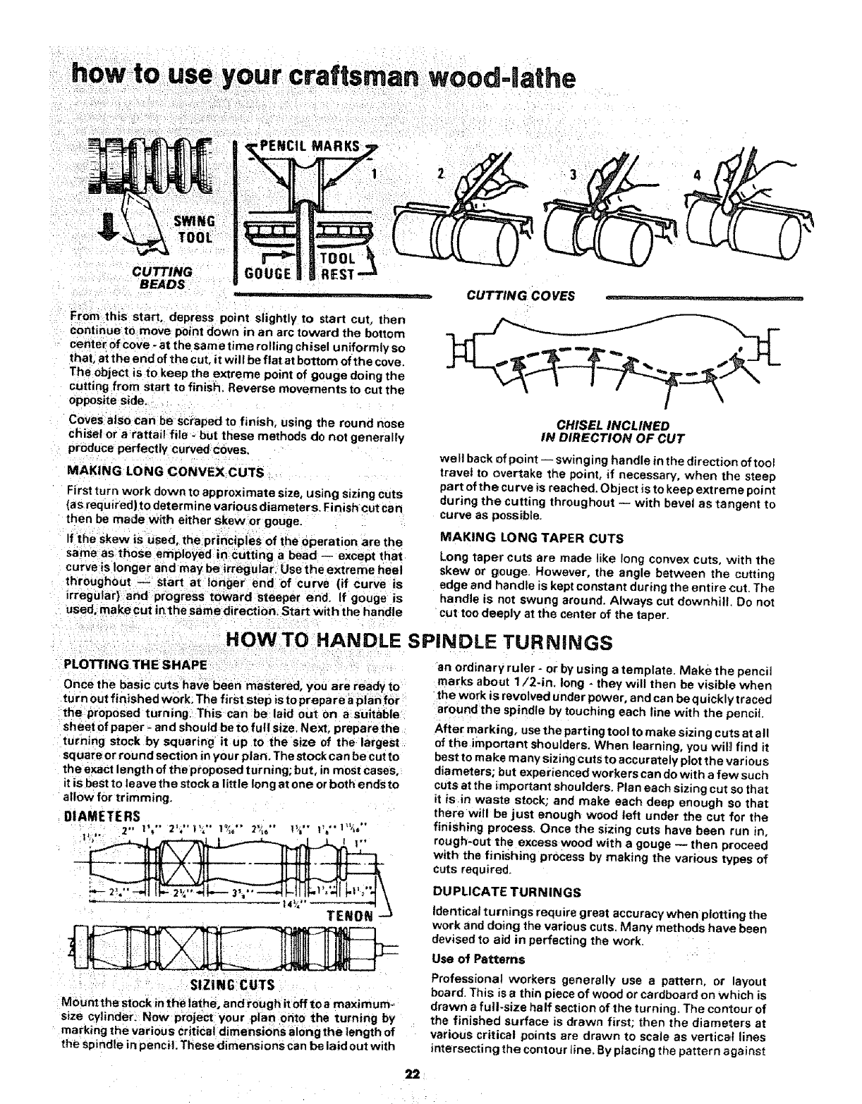
From this start, depress point slightly to start cut, then
continue to move point down in an arc toward the bottom
center of cove - at the same time rolling chisel uniformly so
that, at the end of the cut, it will be flat at bottom of the cove.
The object is to keep the extreme point of gouge doing the
cutting from start to finish. Reverse movements to cut the
opposite side,
Coves also can be scraped to finish, using the round nose
chisel or a rattail file -but these methods do not generally
produce perfectly curved COves,
MAKING LONG CONVEX CUTS
First turn work down to approximate size, using sizing cuts
(as required) to determine various diameters. Finish cut can
then be made with either skew or gouge.
If the skew is Used, the principles of the operation are the
same as those employed in cutting a bead -- except that
curve is longer and may be irregu ar. Use the extreme heel
throughout -_ start at onger end of curve (if curve is
irregular) and progress toward steeper end. If gouge is
used. make cut inthe same direction. Start with the handle
CUTTING COVES .......... '_
CHISEL INCLINED
IN DIRECTION OF CUT
well back of point -- swinging handle in the direction of tool
travel to overtake the point, if necessary, when the steep
part of the curve is reached. Object is to keep extreme point
during the cutting throughout -- with bevel as tangent to
curve as possible.
MAKING LONG TAPER CUTS
Long taper cuts are made like long convex cuts, with the
skew or gouge. However, the angle between the cutting
edge and handle is kept constant during the entire cut. The
handle is not swung around. Always cut downhill. Do not
cut too deeply at the center of the taper.
PLOTTING THE SHAPE
HOW TO HANDLE
Once the basic cuts have been mastered, you are ready to
turn out finished work,The first step is to prepare a plan for
the proposed turning. This can be laid out on a suitable
sheet of paper- and should be to full size, Next, preparethe
turning stock by squaring it up to the size of the largest
square or round section in you r plan. The stock can be cut to
the exact length of the proposed turning; but, in most cases,
itis best to leave the stock alittle long st one orboth ends to
allow for trimming.
DIAMETERS
i:'
_= _4%"_ \
SIZING CUTS
Mountthe stock inthe lathe, and rough it off to a maximum-
size cylinder. Now project your plan onto the turning by
marking the various critical dimensions along the length of
the spindle in penci!. These dimensions can be laid out with
SPINDLE TURNINGS
an ordinary ruler - or by using a template. Make the pencil
marks about 1/2-in_ long - they will then be visible when
the work is revolved under power, and can be quickly traced
around the spindle by touching each line with the pencil
After marking, usethe parting tool to make sizing cuts at all
of the important shoulders. When learning, you will find it
best to make many sizing cuts to accurately plot the various
diameters; but experienced workers can do with a few such
cuts at the important shoulders. Plan each sizing cut so that
it is in waste stock; and make each deep enough so that
there will be just enough wood left under the cut for the
finishing process. Once the sizing cuts have been run in,
rough-cut the excess wood with a gouge -- then proceed
with the finishing process by making the various types of
cuts required.
DUPLICATE TURNINGS
Identical turnings require great accuracy when plotting the
work and doing the various cuts. Many methods have been
devised to aid in perfecting the work.
Use of Patterns
Professional workers generally use a pattern, or layout
board. This is a thin piece of wood or cardboard on which is
drawn a full-size half section of the turning. The contour of
the finished surface is drawn first; then the diameters at
various critical points are drawn to scale as vertical lines
intersecting the contour tine. By placing the pattern against
22

the roughed-off cylinder, you can quickly mark the various
points of the critical diameters. To make each sizing cut, use
outside calipers and set these by actually measuring the
length of the vertical line on the pattern which represents
the diameter desired. Then make the sizing cut, down to the
proper diameter by using the calipers to determine when
the cut is finished. After making the sizing cuts, hang the
pattern behind the lathe where it will serve as a guide for
completion of the workpiece.
Using a Template and a Diameter Board
When many identical turnings are to be produced, it is a
convenience to have a prepared template. This can be made
of thin wood or cardboard -- and is cut on aband saw or
scroll saw to have the exact contour of the finished turning.
The number one finished turning can also be used as a
template. Attach the template to a board; then mount the
board behind the lathe, on hinges, so that the template can
be moved down to touch the workplace and allow you to
closely observe progress of your work.
USING A
TEMPLATE
USING A
DIAMETER BOARD
tf a great many turnings are being produced, a diameter
board will save the time used for resetting calipers, This is
simply athin board along the edge of which a number of
semi-circular cuts have been prepared to represent all the
various caliper settings required for measuring the sizing
cuts. Each semi-circular cut is held against the workpiece
instead of using the calipers.
USING DIAMETER SIZING GAUGE -24909
Production work can be further speeded by the use of the
Diameter Sizing Gauge -24909 to take the place of caliper
measurements, The positions of the ar ms are set to indicate
the various sizing cuts to be made. Each arm is of such a
length that it will drop all of the way down past the back
side of the workpiece when the wood under it has been cut
out to the desired depth of the sizing cut.
USING COPY CRAFTER - 24907
To make identical spindles for chairs, table tegs, or to
exactly copy an existing turning the Copy Crafter -24907 is
used, Follow the outline of original turning or template and
the cutting tool duplicates the workpiece. Spindle turnings
up to 2-1/2 inches in diameter, 36 inches long can be
duplicated from original turnings; up to 6 inches in diameter;
36 inches long from a template. Shallow faceplate turnings
up to 8 inches in diameter can be duplicated fi:om templates.
LONG SPINDLES
A long turning can be worked in short sections, with joints
arranged to be at shoulders where they will not be noticed.
Long thin work that is likely to whip while turning should be
supported at one or two places by a backstick. This is easy to
make. A Simple one consists of a short length of wood
mounted vertically in an extra tool rest, and notched so that
it can be used to support the spindle from behind. An
improved type -- which uses 2 roller skate wheels to form
the notch -- also is shown.
23
,e your craflsman wood-lathe
+ +!
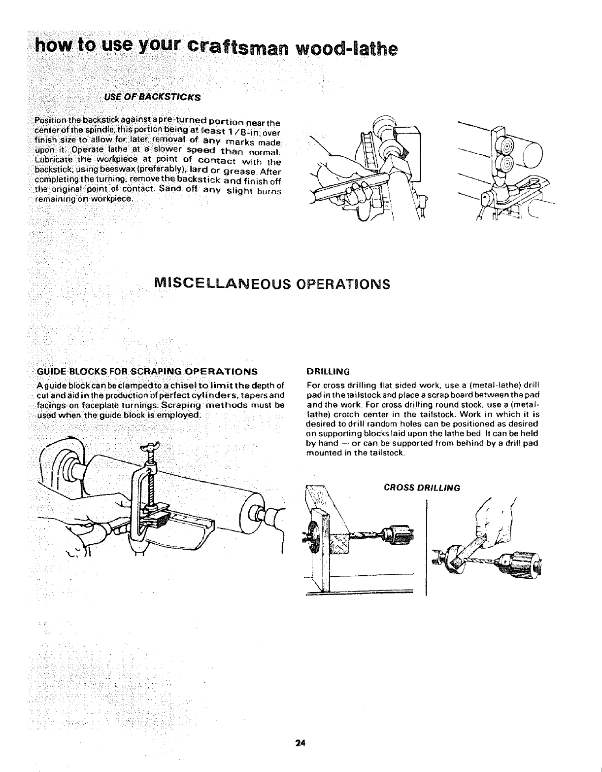
Position the backstick against a pre-turned Portion near the
Center of the spindle, this port on being at least 1/8- n over
finish size to alloW for ater rernovat of any marks made
UpOn itl Operate lathe at aslower speed than norma
LubriCate the workpiece at point of contact with the
backstick; using beeswax (preferably), lard or grease. After
completing the turning, remov e the backstick and f n ish off
the Original: point of cOntact_ Sand off any slight burns
remaining on workp ece.
MISCELLANEOUS OPERATaONS
GUIDE BLOCKS FOR SCRAPING OPERATIONS
A guide block can be clamped to a chise_ to limit the depth of
cut and aid in the production of perfect cylinders, tapers and
facings on faceptate turnings, SCraping methods must be
used when the guide block is employed.
DRILLING
For cross drilling flat sided work, use a (metal-lathe) drilt
pad in the tailst ock and place a scrap board between the pad
and the work. For cross drilling round stock, use a (metal-
lathe} crotch center in the tailstock. Work in which it is
desired to drill random holes can be positioned as desired
on supporting blocks laid upon the lathe bed+ It can be held
by hand -- or can be supported from behind by adrill pad
mounted in the tailstock.
\
CROSS DRILLING
24

FACEPLATE & CHUCK TURNINGS
PLANNING THE WORK
Make a layout first, to provide a visual pattern to follow
while working the turning Patterns can be laid out in the
same manner as spindle patterns -- or templates can be
made which can be held against the work for visual
comparison. Circles to locate the various critical points (at
which the contours of the faceplate take distinct form) can
be quickly scribed on the rotating work by using the
dividers.
PLANNING VARIOUS CUTS
The circumference of a faceplate t urning is roughed-off and
finished in the same manner that a spindle is worked,
Practically all of the balance of the operations, however, are
done by using scraping methods. A few of the standard
contours which must often be turned are illustrated in the
accompanying sketch -- which also shows the proper
chisels for shaping these contours. Any roughing-out to
depth that must be done is generally accomplished with the
gouge held in the scraping position,
DEEP RECESSES
The first step is to remove as much wood as possible by
boring into the center with the largest wood bit available
This can be accomplished as illustrated. Be careful to
measure in advance the depth to which drill can be allowed
to go,
BORING TO DEPTH
Now remove the buik of the waste (to rough-out the desired
recess) by scraping w_ ththe roundnose chisel or the gouge
Remove up Towithin 1 iSdn. of finished size in this manner.
Finish off the inside circumference by scraping with the
spear-point chisel or skew, Smooth the bottom of the recess
by scraping it fiat with the ftatnose chisel.
Proper support must be provided at all times for the
scraping chisels Severat tool rest positions are shown in
the accompanying illustrations. Always endeavor to position
the part of the rest that supports the tool as close to the
working surface as possible.
The depth and squareness of the sides of the recess can be
quickly checked by holding one of the straight sided chisels
and acombination square as shown_
USE OF
TEMPLATE
SPEAR SKEW
so.u ROUNO OSE
NOSE
pLANNING
VARIOUS CUTS
ROUND NOSE
CHISEL SPEAR-POINT
CHISEL
MEASURING
DEPTH
25
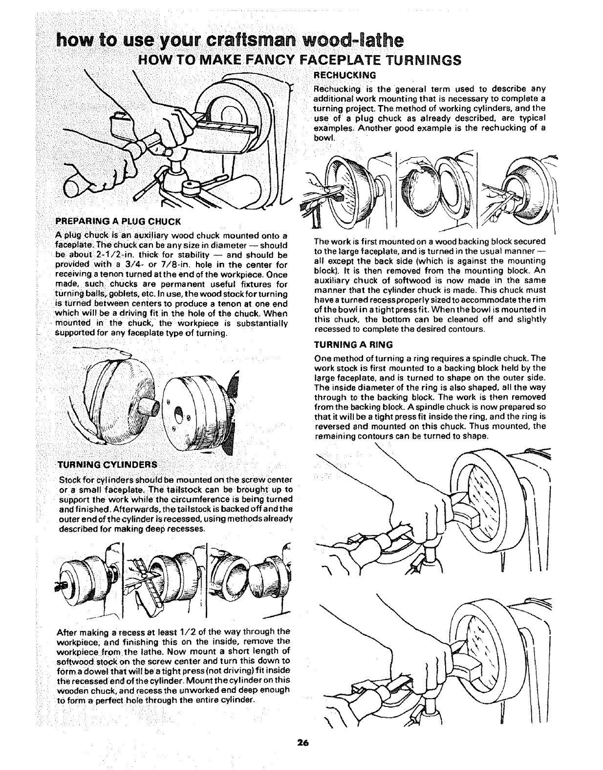
PREPARING A PLUG CHUCK
A plug chuck is an auxiliary wood chuck mounted onto a
faceplate. The chuck can be any size in diameter -- should
be about 2-1/2_in. thick for stability -- and should be
provided with a 3/4- or 7/8-in. hole in the center for
receiving a tenon turned at the end of the workpiece. Once
made, such chucks are permanent useful fixtures for
turning bails, goblets, etc. In use, the wood stockfor turning
is turned between centers to produce a tenon at one end
which wil! be a driving fit in the hole of the chuck. When
mounted in the chuck, the workpiece is substantially
supported for any faceplate type of turning.
Stock for cylinders should be mounted on the screw center
or a small faceplate. The tailstock can be brought up to
support the work while the circumference is being turned
and finished. Afterwards. thetaitstock is backedoff and the
outer end of the cylinder is recessed, using methods already
described fox making deep recesses.
After making a recess at least 1/2 of the way through the
workpiece, and finishing this on the inside, remove the
workpiece from the lathe. Now mount ashort length of
softwood stock on the screw center and turn this down to
form a dowel that will be etight press (not driving) fit inside
the recessed end of the cylinder, Mount the cylinder on this
wooden chuck, and recess the unworked end deep enough
to form a perfect hole through the entire cylinder.
RECHUCKiNG
Rechucking is the general term used to describe any
additiona{ work mounting that is necessary to complete a
turning project, The method of working cylinders, and the
use of a plug chuck as already described, are typical
examples. Another good example is the rechucking of a
bowl,
/
t
The work is first mounted on a wood backing block secured
to the large faceplate, and is turned in the usual manner --
all except the back side (which is against the mounting
block). It is then removed from the mounting block_An
auxiliary chuck of softwood is now made in the same
manner that the cylinder chuck is made. This chuck must
have a turned recess properly sized to accommodate the rim
of thebowt in a tight press fit. When the bowl is mounted in
this chuck, the bottom can be cleaned off and slightly
recessed to complete the desired contours.
TURNING A RING
One method of turning a ring requires a spindle chuck. The
work stock is first mounted to a backing block held by the
large faceptate, and is turned to shape on the outer side.
The inside diameter of the ring is also shaped, all the way
through to the backing block. The work is then removed
from the backing block. A spindle chuck is now prepared so
that it will be a tight press fit inside the ring, and the ring is
reversed and mounted on this chuck. Thus mounted, the
remaining contours can be turned to shape.
26
\
/
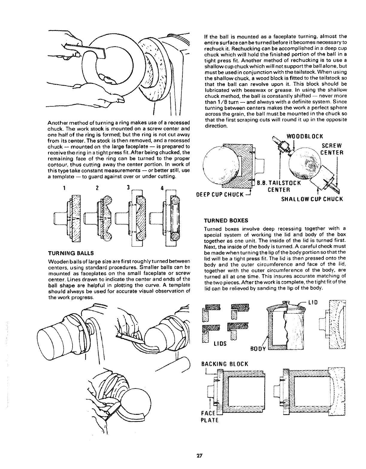
Another method of turning a ring makes use of a recessed
chuck• The work stock is mounted on ascrew center and
one half of the ring is formed; but the ring is not cut away
from its center, The stock is then removed, and a recessed
chuck -- mounted on the large faceplate -- is prepared to
receive the ring in atight press fit. After being chucked, the
remaining face of the ring can be turned to the proper
contour, thus cutting away the center portion. In work of
this type take constant measurements -- or better still, use
a template -- to guard against over or under cutting,
1Z3
TURNING BALLS
Wooden bails of large size are first roughiyturned between
centers, using standard procedures, Smaller balls can be
mounted as faceplates on the small faceptate or screw
center. Lines drawn to indicate the center and ends of the
ball shape are heipful in plotting the curve. A template
should always be used for accurate visual observation of
the work progress.
If the ball is mounted as a faceplate turning, almost the
entire surface can be turned before it becomes necessary to
rechuck it. Rechucking can be accomplished in adeep cup
chuck which wil! hold the finished portion of the bail in a
tight press fit. Another method of rechucking is to use a
shallow cup chuck which wilt not support the bail alone, but
must be used in conjunction with the tailstock. When using
the shallow chuck, a wood block is fitted to the tailstock so
that the ball can revolve upon it. This block should be
lubricated with beeswax or grease• In using the shallow
chuck method, the ball is constantly shifted -- never more
than 1/8 turn -- and always with a definite system. Since
turning between centers makes the work a perfect sphere
across the grain, the ball must be mounted in the chuck so
that the first scraping cuts will round it up in the opposite
direction.
/,
f
\
DEEP CUP CHUCK
WOODBLOCK
SCREW
CENTER
B.B. TAILSTOCK
CENTER
SHALLOW CUP CHUCK
TURNED BOXES
Turned boxes involve deep recessing together with a
special system of working the lid and body of the box
together as one unit. The inside of the lid is turned first.
Next, the inside of the body is turned. Acareful check must
be made when turning the lip of the body portion so that the
lid will be a tight press fit. The lid is then pressed onto the
body anc_ the outer circumference and face of the tid,
together with the outer circumference of the body, are
turned atl at one time. This insures accurate matching of
the two pieces. After the work is complete, the tight fit of the
lid can be relieved by sanding the lip of the body.
LtD .... "_
L i ii
BACKING BLOCK
FAC_E __s _ _:
PLATE
i--
[..L.
27
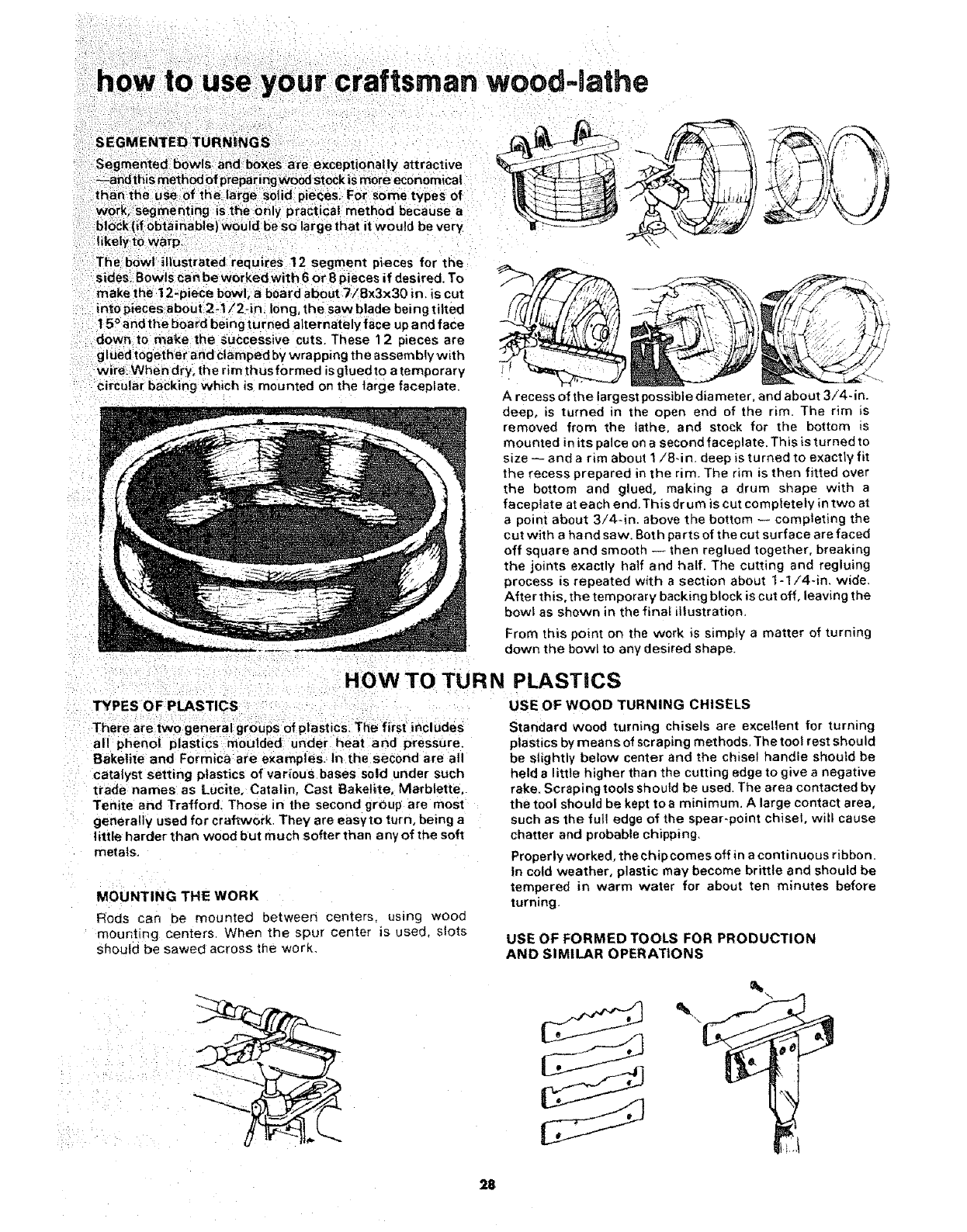
your craftsman woodqathe
very
isegment pieces for the
sides, Bow ( or 8 pieces if desired. To
make the 12-piece bowl, a board about 7/Bx3x30 in. is cut
into pieces about 2-t !2-in, long, the saw blade being tiffed
15°and the board being turned alternately face up and face
down to make the successive cuts. These 12 pieces are
glued together and clamped by wrapping the assembh/with
wire. When dry, the rim thus formed is glued to atemporary
circular backing which _s mounted on the large faceplate. Arecess of the largest possible dia meter, and about 3/4-in.
deep, is turned in the open end of the rim. The rim is
removed from the lathe, and stock for the bottom is
mounted in its palce on a second faceplate. This is turned to
size -- and a rim about 1/8-in. deep is turned to exactly fit
the recess prepared in the rim. The rim is then fitted over
the bottom and glued, making a drum shape with a
faceplate at each end.This dr um is cut completely in two at
a point about 3/4-in. above the bottom -- completing the
cut with a hand saw. Both parts of the cut surface ere faced
off square and smootn -- then reglued together, breaking
the joints exactly half and half. The cutting and regluing
process is repeated with a section about 1-1/4-in. wide.
After this, the temporary backing block is cut off, leaving the
bowl as shown in me finat illustration.
From this point on the work is simply a matter of turning
down the bowl to any desired shape.
HOW TO TURN
TYPES OF PLASTICS
There are two general groups of plastics. The first includes
all phenol plastics moulded under heat and pressure.
Bakelite and Formica are examples. In the second are all
catalyst Setting plastics of various bases sold under such
trade names as Lucite, Catalin, Cast Bakelite, Marblette.
Tenite and Trafford. Those in the second group are most
generally used for craftwork. They are easyto turn, being a
little harder than wood but much softer than any of the soft
metals.
MOUNTING THE WORK
Rods can be mounted between centers, using wood
mounting centers When the spur center is used. slots
should be sawed across the work,
PLASTICS
USE OF WOOD TURNING CHISELS
Standard wood turning chisels are excellent for turning
plastics by means of scrap=rigmethods, The toot rest should
be slightly below center and the chisel handle should be
held a little higher than the cutting edge to give a negative
rake. Scraping tools should be used. The area contacted by
the tool should be kept toe minimum. A large contact area,
such as the full edge of the spear-point chisel, wilt cause
chatter and probable chipping,
Properly worked, the chip comes off in a continuous ribbon,
In cold weather, plastic may become brittle and should be
tempered in warm water for about ten minutes before
turning.
USE OF FORMED TOOLS FOR PRODUCTION
AND SIMILAR OPERATIONS
\
28
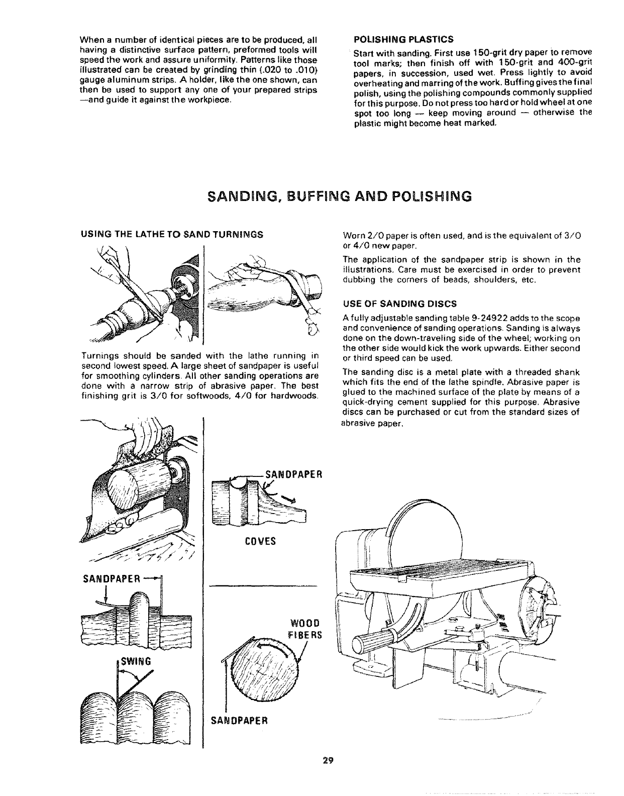
When a number of identical pieces are to be produced, all
having a distinctive surface pattern, preformed tools will
speed the work and assure uniformity_ Patterns like those
illustrated can be created by grinding thin (_020 to .010)
gauge aluminum strips. A holder, like the one shown, can
then be used to support any one of your prepared strips
--and guide it against the workpiece.
POLISHING PLASTICS
Start with sanding. First use 150-grit dry paper to remove
tool mar_s, then finish off with 150-grit and 400-grit
papers, in succession, used wet. Press lightly to avoid
overheat ing and marring of the work. Buffing gives the final
polish, using the polishing compounds commonly supplied
for this p_rpose. Do not press too ha rd or hold wheel at one
spot too long -- keep moving around -- otherwise the
plastic might become heat marked.
SANDBNG, BUFFBNG AND POLISHING
USING THE LATHE TO SAND TURNINGS
Turnings should be sanded with the lathe running in
second towest speed, Alarge sheet of sandpaper is useful
for smoothing cylinders. All other sanding operations are
done with a narrow strip of abrasive paper. The best
finishing grit is 3/0 for softwoods, 4/0 for hardwoods,
SANDPAPER
PER
COVES
WOOD
FIBERS
SANDPAPER
29
Worn 2/0 paper is often used. and is the equivalent of 3/0
or 4/0 new paper.
The application of the sandpaper strip is shown in the
illustrations, Care must be exercised in order to prevent
dubbing the corners of beads, shoulders, etc.
USE OF SANDING DISCS
Afully adjustable sanding table 9-24922 adds to the scope
and convenience of sanding operations. Sanding is always
done on the down-traveling side of the wheel; working on
the other s_de would kick the work upwards. Either second
or third speed can be used.
The sanding disc is a metal plato with a threaded shank
which fits the end of the lathe spindle. Abrasive paper is
glued to the machined surface of the plate by means of a
quick-drying cement supplied for this purpose, Abrasive
discs can be purchased or cut from the standard sizes of
abrasive paper,
/
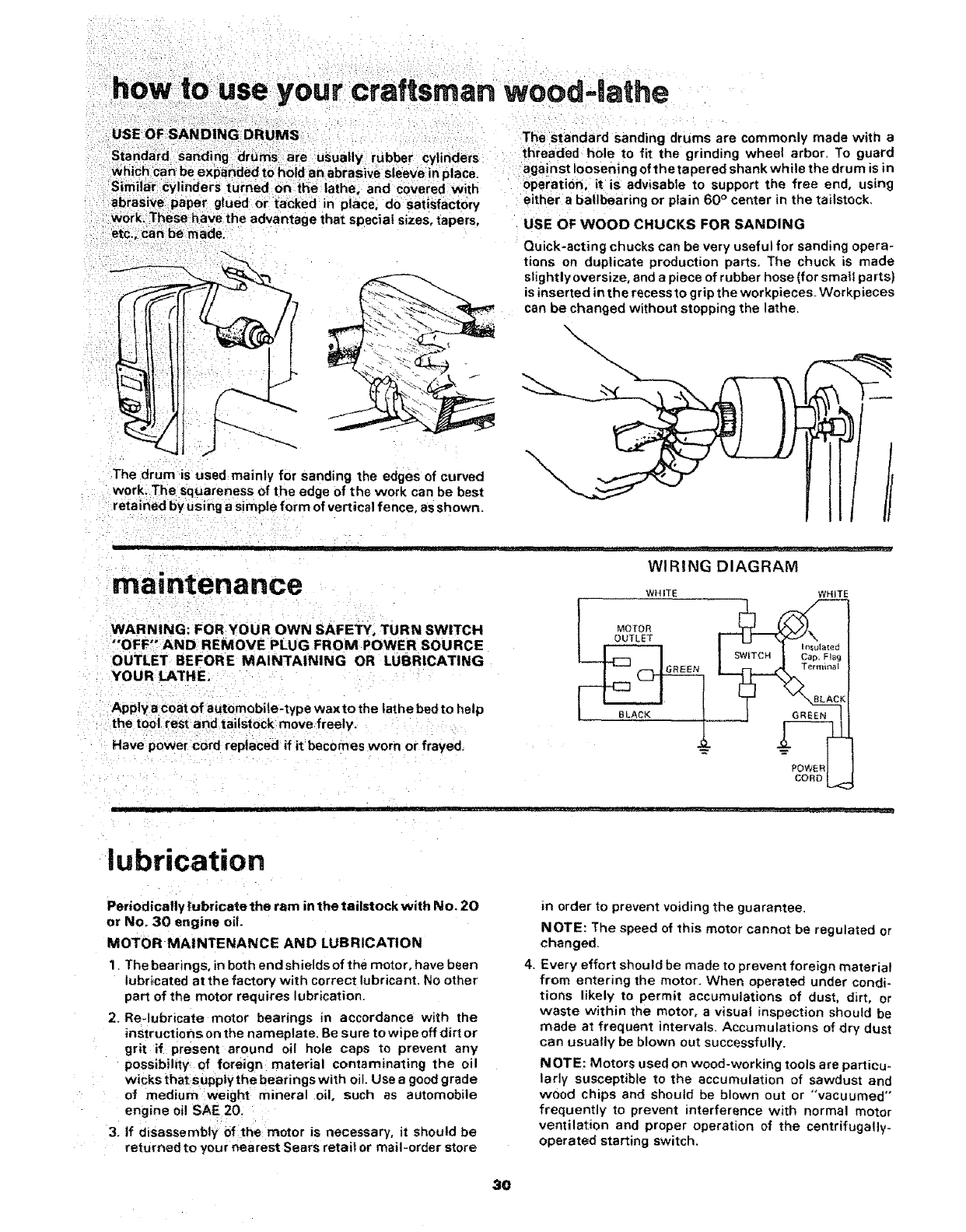
your craftsman wood-lathe
The standard sanding drums are commonly made with a
•e ly rubber cylinders threaded hole to fit the grinding wheel arbor. To guard
against loosening of the tapered shank while the drum is in
urned on the lathe, and covered with operation, it is advisable to support the free end, using
either a ba|lbearing or plain 60 ° center in the tailstock,
glued or tacked in place, do satisfactory
=rage that special sizes, tapers. USE OF WOOD CHUCKS FOR SANDING
Quick-acting chucks can be very useful for sanding opera-
tions on duplicate production parts. The chuck is made
slightly oversize, and a piece of rubber hose (for small partS)
is inserted in the recess to grip the workpieces. Workpieces
(
The drum is used mainly for sanding the edges of curved
work. The squareness of the edge of the work can be best
retained by using a simple form of vertical fence, as shown.
can be changed without stopping the lathe.
X
ill rllll
maintenance
iJ JJ [LJH _ _rJ_ ...........
WIRING DIAGRAM
WHITE WHITE
WARNING: FOR YOUR OWN SAFETY, TURN SWITCH
"'OFF" AND REMOVE PLUG FROM POWER SOURCE
OUTLET BEFORE MAINTAINING OR LUBRICATING
YOUR LATHE.
Apply a coat of automobile-type wax to the lathe bed to help
the tool rest and tailstock move freely.
Have power cord replaced if it becomes worn or frayed_
MOTOR
OUTLET
SWITCH
BLACK GREEN
2-
POWER
CORD
lubrication
Periodically lubricate the ram in the tailstock with No. 20
or No. 30 engine oil.
MOTOR MAINTENANCE AND LUBRICATION
1. Thebearings, in both end shields of the motor, have been
lubricated at the factory with correct lubricant. No other
part of the motor requires lubrication.
2. Re-lubricate motor bearings in accordance with the
instructions on the nameplate, Be sure to wipe off dirt or
grit if present around oil hole caps to prevent any'
possibility of foreign material contaminating the oil
wicks that suppiy the bearings with oil. Use a good grade
of medium weight mineral oil. such as automobile
engine oi! SAE 20:
i
3. If disassembly of the: motor is necessary, it should be
returned to your nearest Sears retail or mail-order store
in order to prevent voiding the guarantee,
NOTE: The speed of this motor cannot be regulated or
changed.
4. Every effort should be made to prevent foreign material
from entering the motor, When operated under condi-
tions likely to permit accumulations of dust, dirt, or
waste within the motor, a visual inspection should be
made at frequent intervals. Accumulations of dry dust
can usually be blown out successfully.
NOTE: Motors used on wood-working tools are particu-
larly susceptible to the accumulation of sawdust and
wood chips and should be blown out or "vacuumed"
frequently to prevent interference with normal motor
ventilation and proper operation of the centrifugally.
operated starting switch.
3O
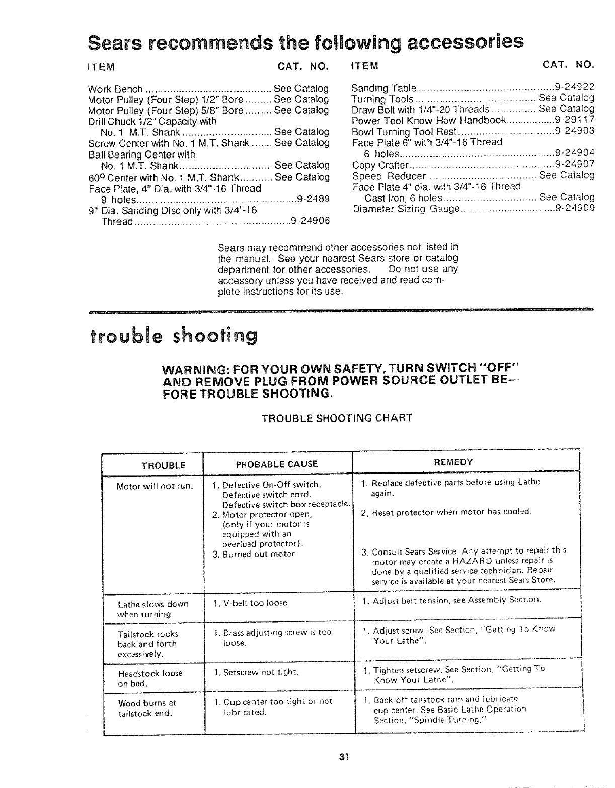
Sears recommends the following accessories
ITEM CAT. NO. ITEM CAT, NO.
Work Bench .......................................... See Catalog
Motor Pulley (Four Step) 1/2" Bore ......... See Catalog
Motor Pulley (Four Step) 5/8" Bore .......... See Catalog
Drill Chuck 1/2" Capacity with
No. 1 MT. Shank .............................. See Catalog
Screw Center with No. 1 M.T. Shank ....... See Catalog
Ball Bearing Center with
No. 1 M.T. Shank ............................... See Catalog
60° Center with No. 1 M.T. Shank ........... See Catalog
Face Plate, 4" Dia. with 3/4"-!6 Thread
9 holes ...................................................... 9-2489
9" Dia. Sanding Disc only with 3/4"-16
Thread .................................................... 9-24906
Sanding Table ............................................. 9-24922
Turning Tools ........................................ See Catalog
Draw Bolt with 1/4"-20 Threads ............... See Catalog
Power Tool Know How Handbook ................. 9-29117
Bowl Turning Tool Rest ................................ 9-24903
Face Plate 6" with 3/4"-16 Thread
6 holes .................................................... 9-24904
Copy Crafter ................................................ 9-24907
Speed Reducer ..................................... See Catalog
Face Plate 4" dia. with 3/4"-16 Thread
Cast Iron, 6 holes ............................... See Catalog
Diameter Sizing Gauge ................................. 9-24909
Sears may recommend other accessories not listed in
the manual. See your nearest Sears store or catalog
department for other accessories. Do not use any
accessory unless you have received and read com-
plete instructions for its use.
trouble shooting
WARNING: FOR YOUR OWN SAFETY, TURN SWITCH "'OFF"
AND REMOVE PLUG FROM POWER SOURCE OUTLET BE-
FORE TROUBLE SHOOTING.
TROUBLESHOOTING CHART
TROUBLE
Motor will not run.
PROBABLE CAUSE
1. Defective On-Off switch,
Defective switch cord.
Defective switch box receptacle.
2, Motor protector Open,
(only if your motor is
equipped with an
overload protector).
3, Burned out motor
REMEDY
1, Replace defective parts before using Lathe
again.
2, Reset protector when motor has cooled,
3. Consult Sears Service. Any attempt to repair this
motor may create a HAZARD unless repair is
done by a qualified service technician. Repair
service is available at your nearest Sears Store,
Lathe slows down 1, V-belt too loose 1. Adjust belt tension, see Assembly Section.
when turning
Tailstock rocks I, Brass adjusting screw is too I. Adjust screw. See Section, "Getting To Know
back and forth loose. Your Lathe".
excessively.
Headstock loose 1. Setscrew not tight, l, Tighten setscrew. See Section, "Getting To
on bed, Know Your Lathe",
Wood burns at 1, Cup center too tight or not !. Back off tailstock ran, and iubricate
taiistock end. lubricated, cup center. See Basic Lathe Operation
Section, "Spindte Turr_ing,"
31
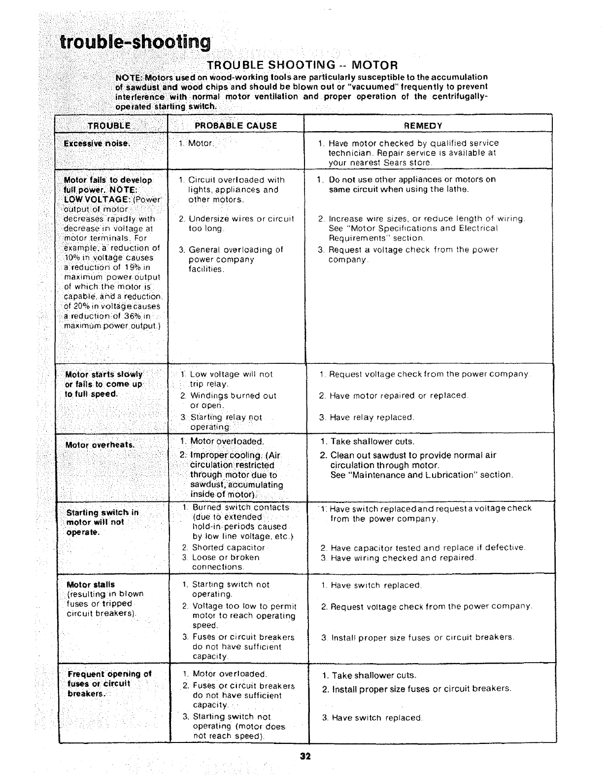
, PROBABLE CAUSE
1. Motor.
. ' ' .,
Motor fails to develop 1. Circuit overloaded with
fu(_l power. NOTE; lights appliances and
LOW VOLTAGE: Power other motors.
output of motor
:decreases rapidly wdh 2. Undersize wires or c_rcud
decrease _n vottage at too long
:-motor terminals. For
example a reduction of 3. Genera[ overloading of
i0% in voltage Causes power company
a reduction of 19% in facilities.
maxtmum power output
of which the motor is
capable, and a reduction
of 20% m voltage causes
areduction of 36% m
maximum power output.)
t Low voltage will not
or falls to come up trip relay.
2 Windings burned out
or open.
3: Starting relay not
operating
1. Motor overloaded.
: 2, improper cooling, (Air
: circulation restr cted
: through factor due to
' sawdust, accumulating
inside of motor).
' ' ." .1 Burned switch contacts
Start ng switch in "(due tO extended
motor will not ' hold-in periods caused
operate.
Motor stalls
(resulting m blown
fuses or tripped
circuit breakers).
Frequent opening of
fuses or circuit
breakers.
i
i ,
by low line voltage, etc.)
Shorted capamtor
Loose or broken
connections.
1. Starting sw_tch not
operating
2. Voltage too low to permit
motoT to reach operating
speed.
3. Fuses or circuit breakers
do not have sufficient
capacity.
1. Motor overloaded.
2. Fuses or circuit breakers
do not have sufficient
capacity.
3. Starting sw_tch not
operating (motor does
not reach speed).
REMEDY
t. Have motor checked by qualified service
technician. Repair serwce is available at
your,nearest Sears store.
I. Do not use other appliances or motors on
same circuit when using the lathe.
2. Increase w_re sizes, or reduce length of wiring
See "Motor Specifications and Electnca_
Requirements" section,
3, Request a voltage check from the power
company.
1. Request voltage check from the power company
2 Have motor repaired or replaced
3. Have relay replaced.
1. Take shallower cuts.
2. Clean out sawdust to provide normal air
circulation through motor.
See "Maintenance and Lubrication" section.
1. Have switch replaced and request a voltage check
from the power company.
2. Have capacitor tested and replace =f defechve
3 Have wiring checked and repaired.
1. Have swttch replaced
2. Request voltage check from the power company.
3 Install proper s_ze fuses or circuit breakers
1. Take shallower cuts.
2. install proper size fuses or circuit breakers.
3. Have switch replaced.
32
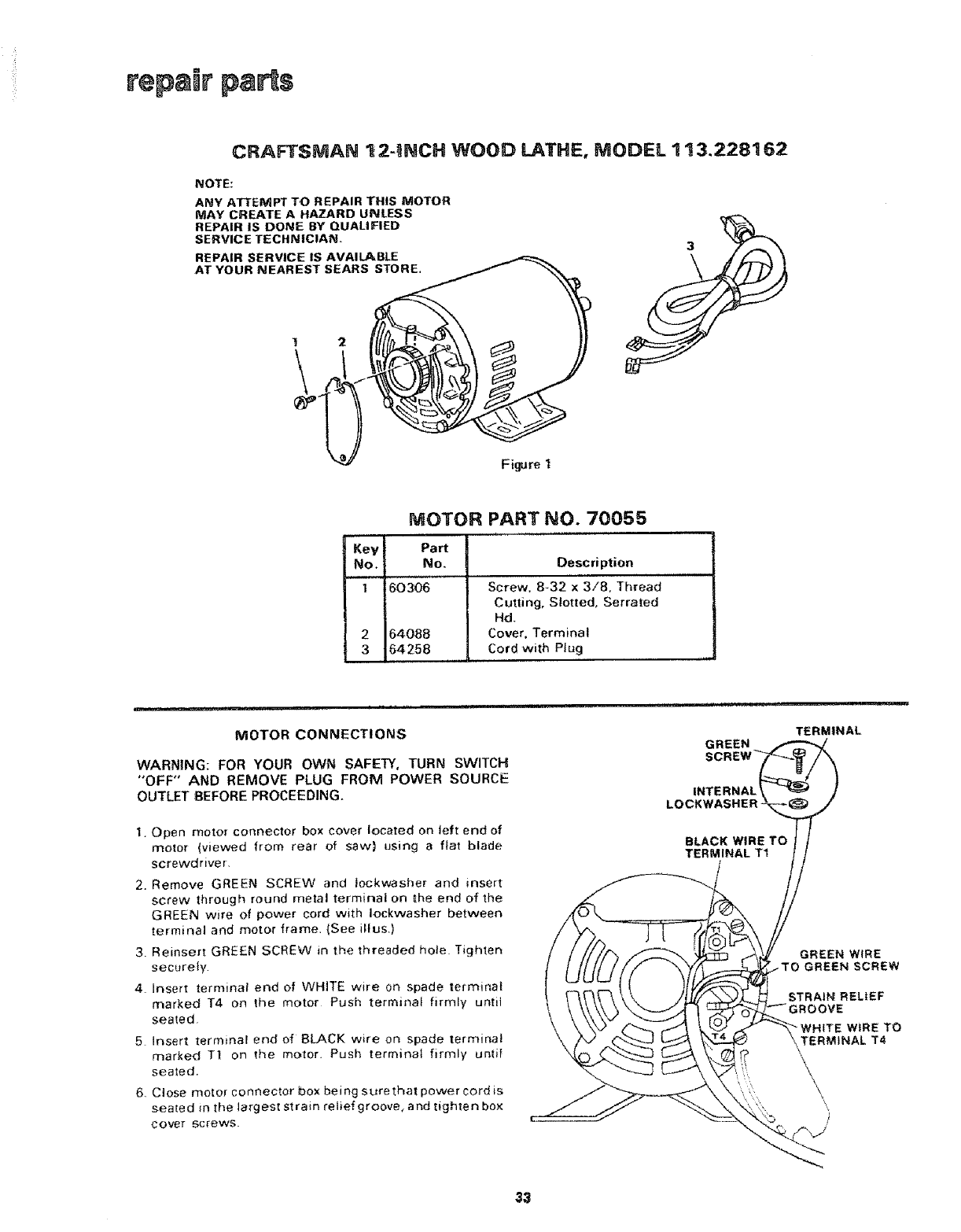
rep=ir pans
CRAFTSMAN "_2-iNCH WOOD LATHE, MODEL 113,228162
NOTE:
ANY ATTEMPT TO REPAIR THIS MOTOR
MAY CREATE A HAZARD UNLESS
REPAIR IS DONE BY QUAUFIED
SERVICE TECHNICIAN.
REPAIR SERVICE IS AVAILABLE
AT YOUR NEAREST SEARS STORE.
t2
Figure I
MOTOR PART NO. 70055
Key Part
No. No. Description
I 6030(_ Screw. 8-32 x3/8, Thread
Cutting, Slotted, Serrated
Hd.
2 64088 Cover. Terminal
3 64258 Cord with Plug
MOTOR CONNECTIONS
WARNING: FOR YOUR OWN SAFETY, TURN SWITCH
"OFF" AND REMOVE PLUG FROM POWER SOURCE
OUTLET BEFORE PROCEEDING.
1. Open motor connector box cover located on left end of
motor (viewed from rear of saw) using a flat blade
screwdriver,
2. Remove GREEN SCREW and iockwasher and insert
screw through round metal terminal on _he end of the
GREEN wire of power cord with leckvvasher between
terminal and motor frame. {See iHus,)
3. ReinsertGREEN SCREW in the threaded hole Tighten
securely
4. Insert terminal end of WHITE wire on spade _erminat
r'narked T4 on the motor Push terminal firmly until
seated,
5Insert terminai end of BLACK wire on spade terminal
marked T1 on the motor. Push terminal firmly until
seated.
6. Close motor connector box being surethat power cord is
seated in the largest strain retief groove, and tighten box
cover screws.
GREEN
INTERNAL
LOCKWASHER
BLACK WIRE TO
TERMINAL TI
m
TERMINAL
GREEN WIRE
-TO GREEN SCREW
STRAIN RELIEF
WIRE TO
TERMINAL T4
,\
33
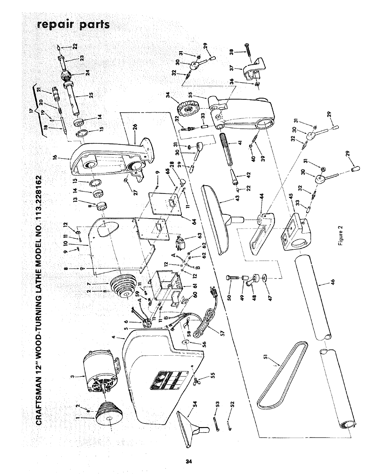
\\ ,c
c_
0
\
\\
\\
\
\
34

(N
e_
6
Z
LU
O
O
LU
k-
O
Z
m
Z
a:
k-
i
O
O
04
Z
g)
k-
U.
<
O
c
,_o
a
_6
N _z
ILl
D
.£
o
O
>. •
vZ
O0 0
_o_ N o_o_oo o_o_ mo _oo_
_O _OOO_O_ OOOOOO_ _O oo_O
_O_ 0 _
?
>.
E
23 --
©
o _E
OZ >'0
2. g _.
I S _u
"u :_ ._
"r E _
mm ©
35
