Craftsman 113232240 User Manual 6 1/8 INCH JOINTER/PLANER Manuals And Guides L0806062
CRAFTSMAN Jointer/Planer Manual L0806062 CRAFTSMAN Jointer/Planer Owner's Manual, CRAFTSMAN Jointer/Planer installation guides
User Manual: Craftsman 113232240 113232240 CRAFTSMAN 6 1/8 INCH JOINTER/PLANER - Manuals and Guides View the owners manual for your CRAFTSMAN 6 1/8 INCH JOINTER/PLANER #113232240. Home:Tool Parts:Craftsman Parts:Craftsman 6 1/8 INCH JOINTER/PLANER Manual
Open the PDF directly: View PDF ![]() .
.
Page Count: 40
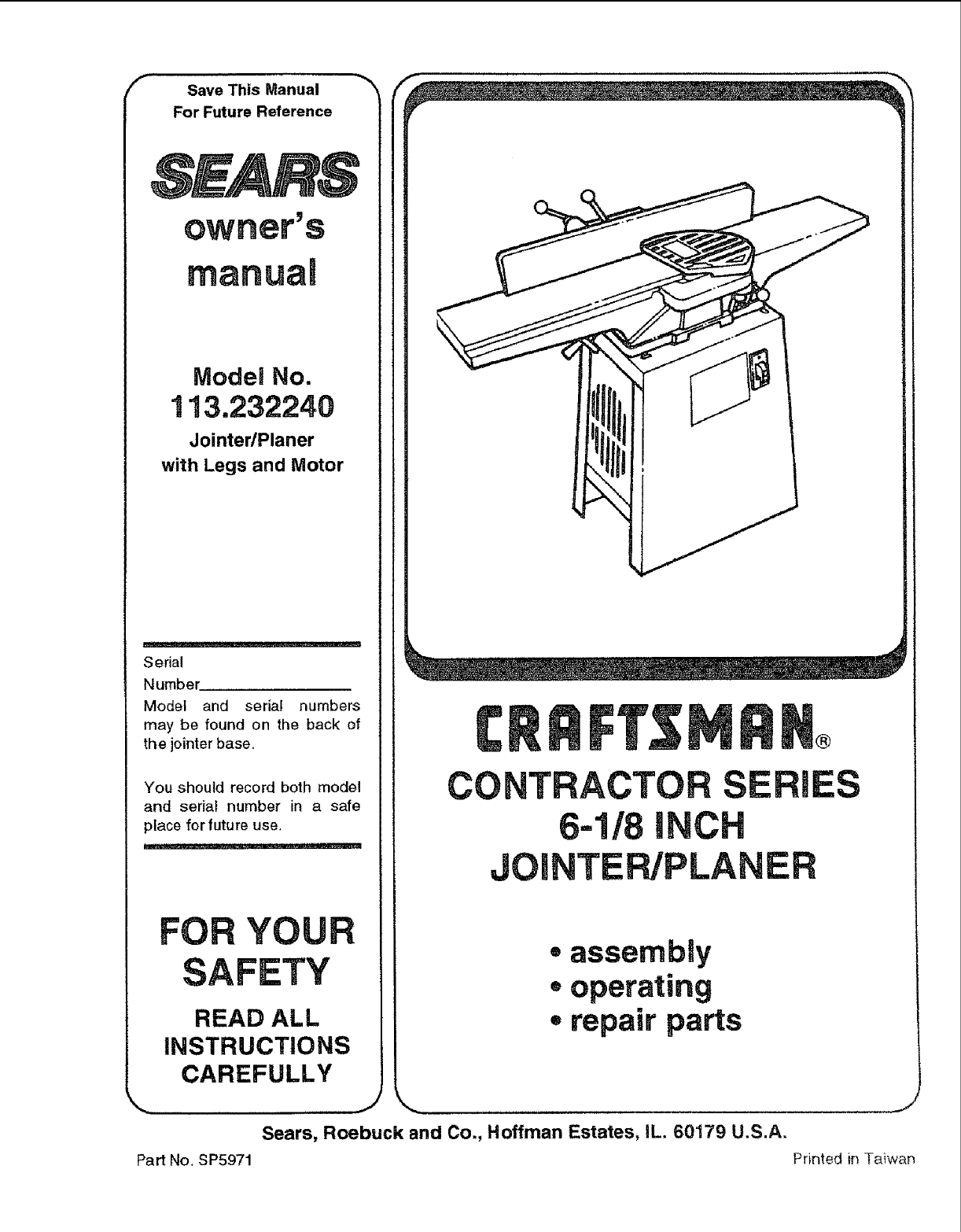
fSave This Manual -_
For Future Reference
ModeJ No.
113,232240
Jointer/Planer
with Legs and Motor
Serial
Number
Model and serial numbers
may be found on the back of
the jointer base.
You should record both model
and serial number in a safe
place for future use.
YOU
SAFETY
READ ALL
INSTRUCTIONS
CAREFULLY
CONTRACTOR ES
6-1/8 I
JOmNTEPJPLANER
Part No, SP5971
• assembly
. operating
• repair parts
Sears, Roebuck and Co., Hoffman Estates, IL. 60179 U.S.A.
J
Printed inTaiwar_
!:i! !ii!i i¸I!!ii/! i ill ! !
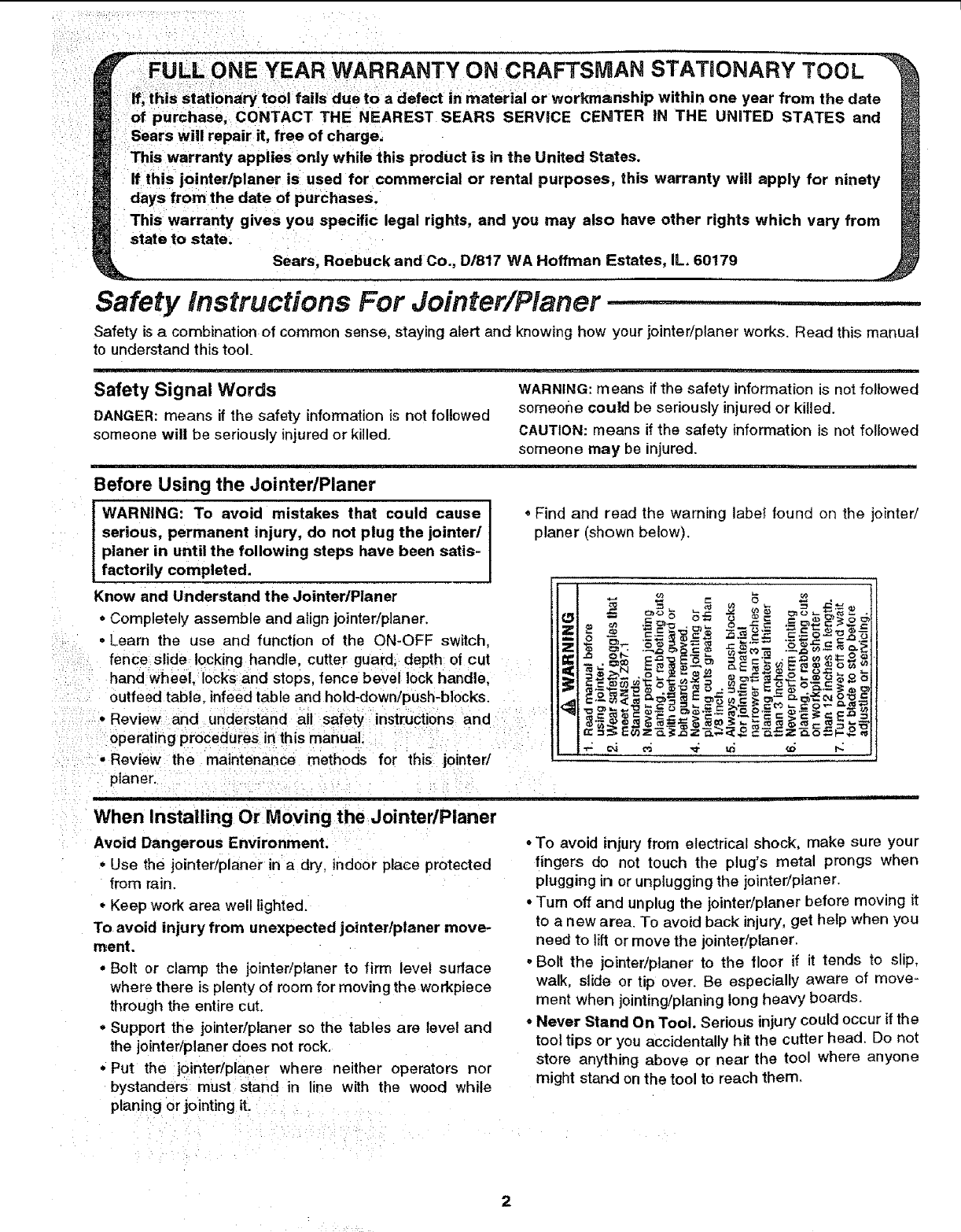
HYEAR WARRANTY ON CRAFTSMAN STATIONARY TOOL
ie toa defect in material or workmanship within one year from the date
purchasei CONTACT THE NEAREST SEARS SERVICE CENTER iN THE UNITED STATES and
:Sears will repair it, free of charge,
This warranty applies only while this prodUct is in the United States.
this jointer/planer is used for commercial or rental purposes, this warranty will apply for ninety
days from the date of purchases.
This warranty gives you specific legal rights, and you may also have other rights which vary from
state to statei Sears, Roebuck and Co., D/817 WA Hoffman Estates, IL 60179
Safety instructions For Jointer/Planer ....
Safety is acombination of common sense, staying alert and knowing how your jointer/planer works. Read this manual
to understand this tool.
J ±J ..... -==-..-Juu--=__ i_ _iiiii, i
Safety Signal Words WARNING: means if the safety information is not followed
DANGER: means if the safety information is not followed someone could be seriously injured or killed.
someone will be seriously injured or killed. CAUTION: means if the safety information is not followed
someone may be injured.
,u .......
Before Using the Jointer/Pianer
WARNING: To avoid mistakes that could cause
serious, permanent injury, do not plug the jointer/
planer in until the following steps have been satis-
factorily completed.
Know and Understand the JointertPlaner
* Completely assemble and align jointer/planer. Z
. Learn the use and function of the ON-OFF switch, _.
fence slide locking handle, cutter guard; depth of cut
hand wheel. Iocks and stops, fence bevel lock handle,
outfeed table, infeed table and hold-down/push-blocks. <_
•Review and understand all safety instruCtions and
operating procedures in this manual.
'.....
•Review the maintenance methods for this jointed
planer.
When Installing Or Moving the Jointer/Pianer
Avoid Dangerous Environment.
•Use the jointer/planer in a dry, indoor place protected
from rain
° Keep work area well lighted.
To avoid injury from unexpected jointer/planer move-
ment.
• Bolt or clamp the jointeriplaner to firm level surlace
where there is plenty of room for moving the workpiece
through the entire cut.
-Support the jointer/planer so the tables are level and
the jointer/planer does not rock.
•Put the iointer/planer where neither operators nor
bystanders must stand in line with the wood while
planing or jointing it.
,Find and read the warning label found on the jointeri
planer (shown below).
-To avoid injury from electrical shock, make sure your
fingers do not touch the plug's metal prongs when
plugging in or unplugg{ng the jointer/planer.
• Turn off and unplug the jointer/planer before moving it
to a new area. To avoid back injury, get help when you
need to lift or move the jointedplaner.
-Bolt the jointer/planer to the floor if it tends to slip,
walk slide or tip over. Be especially aware of move-
ment when jointing/planing long heavy boards.
°Never Stand On Tool. Serious injury could occur if the
tool tips or you accidentally hit the cutter head. Do not
store anything above or near the tool where anyone
might stand on the tool to reach them,
2
Before Each Use
Inspect your jointer/ptaner.
WARNING: The 2-1/2 inch jointer/planer pulley and
the 3-112 inch motor pulley furnished will run the
cutter head at about 5000 RPM when used with a
3450 RPM motor. Use of different types of pulleys
or motors will change this speed and could cause
jamming, binding, kickback, thrown knives or
other dangers,
.To avoid injury from accidental starting, turn the switch
off, unplug the saw, and remove the switch key before
moving the cutter head guard, changing the blades,
changing the setup, or adjusting anything.
• Check for alignment of moving parts, binding of mov-
ing parts, breakage of parts, unit stability, and any
other conditions that may affect the way the jointed
planer works.
•If any part is missing, bent or broken in any way, or any
electrical part does not work property, turn the jointed
planer off and unplug the jointedplaner.
=Replace damaged, missing or failed parts before using
the jointer/planer again.
• Make sure the cutter guard works properly. With the
switch off and key removed, pull the cutter guard open
and let go. tf the guard doesn't smoothly swing closed,
contact Sears Service Department.
•Make sure the cutter head turns in the right direction.
The top should move toward the infeed table. If the
cutter head turns the wrong direction, contact Sears
Service Department.
• Keep Jointer/Planer interior free of wood chips and
dust buildup around motor and switch box.
• Keep knives sharp. Dull or nicked knives tend to
"pound" and chew at the'wood, causing kickbacks.
° To avoid injury from unsafe accessories, use only rec-
ommended accessories.
Use Recommended Accessories.
°To avoid injury from unsafe accessories, use only rec-
ommended accessories.
Consult the owners manual for recommended accessories.
• Follow the instructionsthat accompany the accessories.
WARNING: Use only accessories recommended
for this jointer/planer. (Using other accessories
Imay be dangerous.)
........................................................ ii i, iii iiiii
To Avoid Injury From Jams, Slips Or Thrown Pieces (Kickbacks Or Throwbacks)
°Use this jointer/planer to cut oniy wood.
• Plan your hand placement so your fingers will not be
anywhere a sudden slip could cause them to slide or
fall into the cutter head. When using onty one hold-
down/push-block to feed the wood, do not put your
other hand on the jointer/planer, workpiece, or hold-
down/push-block.
° To avoid injury from thrown pieces, make sure the
knives are sharp, properly installed and the cutter
knives wedge screws are tight.
•Make sure the clamps and {ocks are tight and there is
not excessive play in any parts.
°Adjust the depth of cut to between 1/32 and 1/16 of an
inch for best results in most operations. A deep cut
makes feeding the wood harder and can cause the
wood to kickback. To be sure you will make a depth of
i ii iiii
cut you planned, always lower the infeed table slightly
farther than you wanted then, raise the table to the
desired depth.
oUse The Right Tool. Don't force toot or attachment to
do a job it was not designed for.
Inspect your work area.
°Keep work area clean.
•Cluttered areas and benches invite accidents.
• Floor must not be slippery from wax or sawdust.
° To avoid bums or other fire damage, never use the
jointer/planer near flammable liquids, vapors or gases.
=Before using the jointer/ptaner, clear the table of aH
objects not needed to feed the workpiece.
•To avoid injury, don't do any layout, assembly, or
setup work on the jointer/ptaner bed.
Plan Ahead To Protect Your Eyes, Hands, Face and Ears
Avoid Accidental Starting.
oMake sure switch is "OFF" before plugging jointed
planer into apower outlet.
Dress for safety.
• Do not wear loose clothing, gloves, neckties or jewelry
(r_ngs,wrist watches), They can get caught and draw
you into moving parts,
•Wear nonslip footwear.
• Tie back long hair.
= Roll long sleeves above the elbow.
•Noise levels vary widely. To avoid possible hearing
damage, wear ear plugs or muffs when using jointed
planer for hours at a time.
• Any jointer/planer can throw foreign objects into the
eyes. This can result in permanent eye damage. Wear
safety goggles (not glasses) that comply with ANSI
Z87,1 (shown on package). Everyday eyeglasses have
only impact resistant lenses. They are not safety
glasses. Safety goggles are available at Sears retail
stores. Glasses or goggles not in compliance with
ANSI Z87.1 could seriously hurt you when they break.
WEAR YOUR
• For dusty operations, wear adust mask along with
safety goggles.
Safety tnstructions For Jointer/Planer (contin,
Inspect your wotkpiece.
• Make sure there are no nails or foreign objects in the
part of the workpiece to be cut.
Plan your cut.
°Small or thin workpieces can kickback when they tip
over on the tables or into the cutter head. To avoid
head contact or workpiece kickback:
- Never joint, plane or bevel workpieces shorter than
12 inches.
°When jointing, beveling or rabbeting:
- Never joint or bevel workpieces less than 3/4 inch
wide or 1/4 inch thick.
- Always use the hold-down/push-blocks when jointing
or beveling wood narrower than 3 inches.
-When rabbeting, always make cuts in 1/8" incre-
ments or less.
o When planing:
- Never plane wood thinner than 1/2 inch.
-Always use hold-down/push-blocks when planing
wood thinner than 3inches.
Whenever JointedPlaner is Running:
WARNING: Don't allow familiarity (gained from fre-
quent use of your jointerlplaner) cause acareless
mistake. Always remember that a careless fraction
of a second is enough to cause a severe injury.
-Before actually cutting with the jointer/planer, let it run
for awhile. If it makes an unfamiliar noise or vibrates a
lot, stop immediately. Turn the jointer/planer off.
Unplug the jointedplaner. Do not restart until finding
oKeep atl visitors a safe distance from the jointedplaner.
-Make Sure bystanders are clear of the jointer/planer
and workpiece.
- Never cut Freehand, Guide your workpiece solidly
against the fence and table top.
- Make sure there's no debris between the workpiece
and its supports.
Use extra caution with large, very small or awkward
workpieces.
•Use extr_ supports (tables, saw horses, blocks, etc.)
for any workpiece large enough to tip when not held
down to the table top. Never use another person as
additional support or to help feed, support or pull the
workpiece.
- Never cut more than one workpiece at atime.
o Never turn your jointer/planer "ON" before clearing
everything except the workpiece and related support
devices offthe table.
oBefore trying a new or little used operation, carefully
plan your hand placement. Make sure you have proper
hold-down/push-blocks, jigs, fixtures, steps, etc. ready
to use.
Don't Force Tool.
°Let the cutter head reach full speed before cutting.
* Feed the workpiece into the jointer/planer only fast
enough to let the tool cut without bogging down or
binding.
Before freeing jammed material.
, Turn switch "OFF'.
oWait for all moving parts to stop.
= Unplug the jointer/planer.
- Check knives for sharpness and nicks before starting
again.
Before Leaving the Jointer/Planer.
=Turn the jointer/planer off. oMake workshop child-proof. Lock the shop. Disconnect
• Wait for knives to come to a complete stop. master switches. Remove the yellow switch key. Store
it away from children and others not qualified to use
-Unplug the jointedplaner, the tool.
Glossary of Terms for Woodworking ........ n
Bed
The combination of infeed and outfeed table surfaces
which support the workpiece during a cutting operation.
Bevel!Chamfer
Removing wood along the edge of a board to make that
edge straight, smooth and angled to the board face which
is against the fence.
Cutter Guard :
Spring loaded guardo_ ishie!d c0vering the cutter head.
Cutter Head
The cutter head is a rotating piece with three adjustable
knives. The cutter head removes material from the work-
piece
Depth of cut
Aterm used to indicate how deep into the workpiece the
cutter knives will cut.
Fence
The fence is attached to the jointer/planer base. The
fence helps support and guide the workpiece as it is
pushed across the cutter head.
Freehand
Using the tool without holding the workpiece firmly
against the fence and table. This can let the workpiece
twist and kick back and must never be attempted.
Gum
A sticky, sap based residue from wood products.
Hold.Down/Push-Blocks
They are required for your own safety. They are used to
hold your wo_pieces against the table and fence when
planing, rabbeting or jointing.
infeed Table
The section of the jointer bed upon which the workpiece
is placed before being pushed into the cutter head.
Infeed table height is adjustable which allows the opera-
tor to select the depth of cut.
Jointing
The removal of wood along the edge of a board so as to
make that edge straight, smooth and square to the board
face which is against the fence.
Kickback
An uncontrolled grabbing and throwing of the workpiece
back toward the operator by the rotating cutter head.
Leading End
The end of the workpiece which is pushed into the cutter
head first.
Ouffeed Table
The section of a jointer bed which supports the workpiece
after it passes over the cutter head.
Planing
Removing wood from the widest surface or face of a
board so as to make it flat and smooth.
Rabbet
A notch cut into the edge of workpiece.
Resin
Asticky, sap based substance that has hardened.
Revolutions Per Minute (RPM)
The number of turns completed by a spinning object in
one minute.
Throw-Back
Throwing of pieces in a manner similar to a kickback.
Trailing End
The workpiece end last cut by the knives.
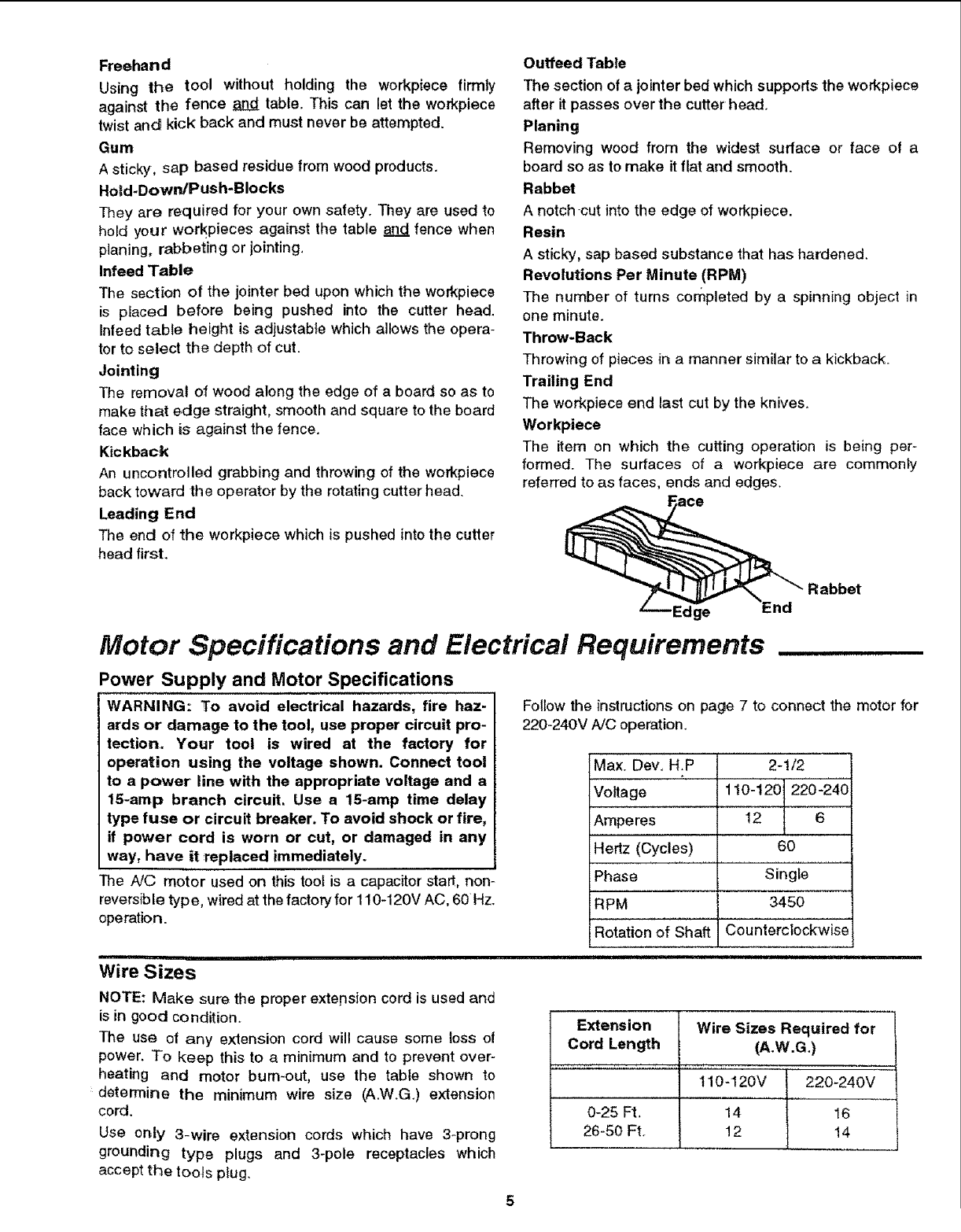
Workpiece
The item on which the cutting operation is being per-
formed. The surfaces of a workpiece are commonly
referred to as faces, ends and edges.
'Edge End
Motor Specifications and Electrical Requirements
Power Supply and Motor Specifications
WARNING: To avoid electrical hazards, fire haz-
ards or damage to the tool, use proper circuit pro-
tection. Your tool is wired at the factory for
operation using the voltage shown. Connect tool
to a power line with the appropriate voltage and a
15-amp branch circuit. Use a 15-amp time delay
type fuse or circuit breaker. To avoid shock or fire,
if power cord is worn or cut, or damaged in any
way, have it replaced immediately.
The A!© motor used on this tool is a capacitor start, non-
reversible typ e, wired at the factory for 110-120V AC, 60 Hz.
operation.
ii !nllllH Ul
Wire Sizes
Follow the instructions on page 7 to connect the motor for
220-240V A/C operation.
Max. Dev, H.P
Voltage
Amperes
Hertz (Cycles)
Phase
RPM
2-1/2
110"120 220-24-0
12 6
60
Single
3450
Rotation of Shaft Counterclockwise
NOTE: Make sure the proper extepsion cord is used and
is in good condition.
The use ot any extension cord will cause some toss o!
power. To keep this to a minimum and to prevent over-
heating and motor bum-out, use the tabte shown to
determine the minimum wire size (A.W.G.) extension
cord.
Use or_ty 3-wire extension cords which have 3_prong
grounding type plugs and 3-pole receptacles which
accept the tools ptug.
q
Extension Wire Sizes Required for |
Cord Length (A.W.G.) /
........... , .......,.......... ,.... !
110-120V 220_240V
0-25 Ft, 14 16
26-50 Ft. 12 14
Motor Speclfic.tions and Eiectr, cat Requirements (continued)
i : i DANGER: To aVoid electrocution: _;_
; I U_e only identical replacement parts when ser-
vicing! Servicing should be performed by a
qualified service technician.
2i Do not use in rain or where floor is wet.
This tool is intended for indoor residential use
;: :only.
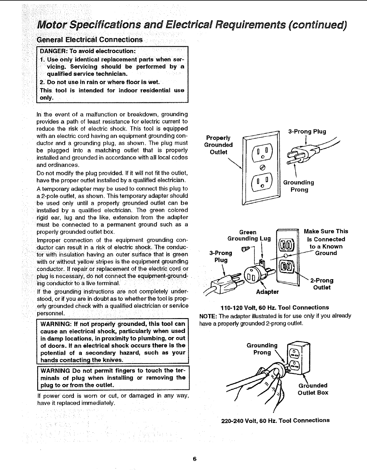
,In _he event of a malfunction or breakdown, grounding
provides a path of least resistance for electric current to
reduce the risk of electric shock. This tool is equipped
with an electric cord having an equipment grounding con-
ductor and a grounding plug, as shown. The plug must
be plugged into a matching outlet that is properly
installed and grounded in accordance with all local codes
and ordinances.
Donot modify the plug provided. If it witt not fit the outlet,
have the proper outlet installed by a qualified electrician.
A temporary adapter may be used to connect this plug to
a 2-pole outlet, as shown. This temporary adapter should
be used only until a properly grounded outlet can be
installed by a qualified electrician. The green colored
rigid ear, lug land the like, extension from the adapter
must be connected to a permanent ground such as a
properly grounded outlet box.
Properly r_
3-Prong Plug
Grounding
Prong
Green _Make Sure This
Improper connection of the equipment grounding con- Grounding ug I__ Is Connected
duct0r Can result in a risk Of electric shock. The conduc- €l"l_ _ to a Known
:i tbr:With insulation having an outer surface that is green 3-Prong v | _ _ Ground
:: Withor without yelloWstripes isthe equipment grounding Plug C ll "_"
: C0nduct0i'. if repairor replacement of the electric cord or \ /'_ _ _,_]_g.J_
plug _s necessary; do not connect the equlpment_ground- _._'_" !_ _ ,] 2-Prong
:: If;the grounding instructions are not completely under- ff'_ Adapter Outlet
sto0d, or if you are in doubt as to whether the tool is prop-
erly groundedbheck with aqualified electrician Or service
personnel. ::_
.... , ,,,,
WARNING: If not properly grounded, this tool can
cause an electrical shock_ particularly when used
in damp locations, in proximity to plumbing, or out
of doors. If an electrical shock occurs there is the
potential of a secondary hazard, such as your
hands contacting the knives.
WARNING Do not permit fingers to touch the ter-
minals of plug when installing or removing the
plug to or from the outlet.
If power cord is worn or cut, or damaged in any way,
have it replaced immediately.
110-120 Volt, 60 Hz. Tool Connections
NOTE: The adapter illustratedis for use only if you already
have a propedy grounded2-prong outlet.
Grounding
Prong
nded
Outlet Box
220-240 Volt, 60 Hz. Tool Connections
Changing Motor Voltage
WARNING: If not properly grounded, this tool can
cause an electrical shock, particularly when used
in damp locations, in proximity to plumbing, or out
of doors. If an electrical shock occurs there is the
potential of a secondary hazard, such as your
hands contacting the knives.
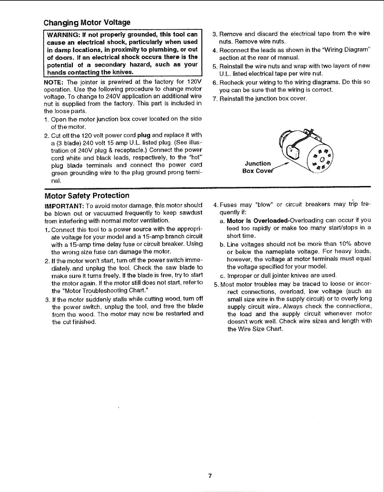
NOTE: The joir_ter is prewired at the factory for 120V
operation. Use the following procedure to change motor
voltage. To char_ge to 240V application an additional wire
nut is supplied from the factory. This part is included in
the loose pads.
1. Open the motor junction box cover located on the side
of the motor.
2. Cut off the 120 volt power cord plug and replace it with
a (3 blade) 240 volt 15 amp U.L. listed plug. (See illus-
tration of 240V plug & receptacle.) Connect the power
cord white and black leads, respectively, to the "hot"
plug blade terminals and connect the power cord
green grounding wire to the plug ground prong termi-
nal.
,, _ ii i i,!l i,
Motor Safety Protection
IMPORTANT: To avoid motor damage, this motor should
be blown out or vacuumed frequently to keep sawdust
from interfering with normal motor ventilation.
1. Connect this toot to a power source with the appropri-
ate voltage for your model and a 15-amp branch circuit
with a 15-amp time delay fuse or circuit breaker. Using
the wrong size fuse can damage the motor.
2. If the motor won't start, turn off the power switch imme-
diately,and unplug the tool. Check the saw blade to
make sure it turns freely. If the blade is free, try to start
the motor again, If the motor still does not start, referto
the "Motor Troubleshooting Chart."
3. If the motor suddenly stalls while cutting wood, turn off
the power switch, unplug the tool, and free the blade
from the wood. The motor may now be restarted and
the cut finished.
3. Remove and discard the electrical tape from the wire
nuts. Remove wire nuts.
4. Reconnect the leads as shown in the "Wiring Diagram"
section at the rear of manual.
5, Reinstall the wire nuts and wrap with two layers of new
U.L. listed electrical tape per wire nut.
6, Recheck your wiring to the wiring diagrams. Do this so
you can be sure that the wiring is correct.
7. Reinstall the junction box cover.
JoU:Cctio_i_
4. Fuses may "blow" or circuit breakers may trip fre-
quently it:
a. Motor Is Overloaded-Overloading can occur if you
feed too rapidly or make too many start/stops in a
short time.
b. Line voltages should not be more than 10% above
or below the nameplate voltage. For heavy loads,
however, the voltage at motor terminals must equal
the voltage specified for your model.
c. Improper or dull jointer knives are used.
5. Most motor troubles may be traced to loose or incor-
rect connections, overload, low voltage (such as
small size wire in the supply circuit) or to overly tong
supply circuit wire.. Always check the connections,
the load and the supply circuit whenever motor
doesn't work well. Check wire sizes and length with
the Wire Size Chart.
7
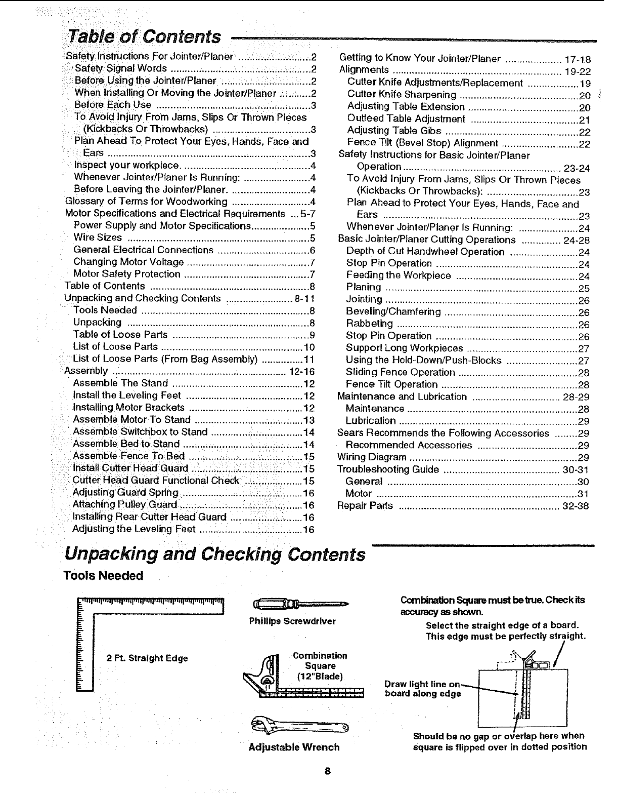
Table of Contents
Safety Instructions For Jointer/Planer .......................... 2
Safety Signal Words ....................... : ................... _......2
Before Using the JointedPlaner ................. ;.............. 2
When Installing Or Moving the Jointer/Planer. .......... 2
Before Each Use ....................................................... 3
: To Avoid Injury' From Jams, Slips Or Thrown Pieces
• (Kickbacks Or Throwbacks) ................................... 3
Plan Ahead To Protect Your Eyes, Hands, Face and
Ears ........................................................................ 3
Inspect your workpiece .............................................. 4
Whenever Jointer/Planer Is Running: ........................ 4
Before Leaving the Jointer/Planer ............................ 4
Glossary of Terms for Woodworking ........................... 4
Motor Specifications and Electrical Requirements ...5-7
Power Supply and Motor Specifications ..................... 5
Wire Sizes ................................................................. 5
General Electrical Connections ................................. 6
Changing Motor Voltage ............................................ 7
Motor Safety Protection ............................................. 7
Table of Contents ......................................................... 8
Unpacking and Checking Contents ....................... 8-11
Tools Needed ............................................................ 8
Unpacking ................................................................. 8
Table of Loose Parts ................................................. 9
List of Loose Parts ................................................... 10
List of Loose Parts (From Bag Assembly) ............... 11
Assembly .............................................................. 12-16
Assemble The Stand ............................................... 12
Install the Leveling Feet .......................................... 12
Installing Motor Brackets ......................................... 12
Assemble Motor To Stand ....................................... 13
Assemble Switchbox to Stand ................................. 14
Assemble Bed to Stand ........................................... 14
Assemble Fence To Bed ......................................... 15
Install Cutter Head Guard ........................................ 15
Cutter Head Guard Functional Check ..................... 15
Adjusting Guard Spring .......................................... 16
Attaching Pulley Guard ............................................ 16
Installing Rear Cutter Head Guard .......................... 16
Adjusting the Leveling Feet ..................................... 16
Getting to Know Your JointedPlaner .................... 17-18
Alignments ............................................................ 19-22
Cutter Knife Adjustments/Replacement .................. 19
Cutter Knife Sharpening .......................................... 20
Adjusting Table Extension ....................................... 20
Outfeed Table Adjustment ...................................... 21
Adjusting Table Gibs ............................................... 22
Fence Tilt (Bevel Stop) Alignment ........................... 22
Safety Instructions for Basic Jointer/Planer
Operation ........................................................ 23-24
To Avoid Injury From Jams, Slips Or Thrown Pieces
(Kickbacks Or Throwbacks): ................................ 23
Plan Ahead to Protect Your Eyes, Hands, Face and
Ears ..................................................................... 23
Whenever JointedPtaner Is Running: ..................... 24
Basic Jointer/Ptaner Cutting Operations .............. 24-28
Depth of Cut Handwhee! Operation ........................ 24
Stop Pin Operation .................................................. 24
Feedin g the Workpiece ........................................... 24
Planing .................................................................... 25
Jointing .................................................................... 26
Beveling/Chamfering ............................................... 26
Rabbeting ................................................................ 26
Stop Pin Operation .................................................. 26
Support Long Workpieces ....................................... 27
Using the Hold-Down/Push-Blocks ......................... 27
Sliding Fence Operation .......................................... 28
Fence Tilt Operation ................................................ 28
Maintenance and Lubrication ............................... 28-29
Maintenance ............................................................ 28
Lubrication ............................................................... 29
Sears Recommends the Following Accessories ........ 29
Recommended Accessories ................................... 29
Wiring Diagram ........................................................... 29
Troubleshooting Guide ......................................... 30-31
General ................................................................... 30
Motor ...................................................................... 31
Repair Parts ......................................................... 32-38
...... i ,i ii
Unpacking and Checking Contents
Tools Needed
2 Ft. Straight Edge
Phillips Screwdriver
Combination
Square
CombinationSquaremust be true. Check its
accuracyasshown.
Select the straight edge of a board.
erfectly straight.
This edge must be _, _/
.... t
Draw light line on---. _ i
board along edge _ I
t
Adjustable Wrench Should be no gap or overlap here when
square is flipped over in dotted position
Unpacking
WARNING: To avoid injury from unexpected starl-
ing or electrical shock, do not plug the power cord
into a power source outlet during Unpacking, until
all assembly steps are complete, and you have
read and understand the safety and operating
instructions.
WARNING: Although compact, this tool is heavy.
To avoid back injury, get help whenever you have
to lift the tool.
Your jointer/planer is shipped complete in one carton and
includes steel legs,
1. Clear yourself a large work area. Remove the jointed
planer and parts from the carton. Lift-the tool at the
bottom of the base.
2. Place the tool on a secure, stationary work surface and
look it over carefully.
3. Separate all parts from packing materiels and check
each one with the "Table of Loose Parts" and the "List
of Loose Parts" to make certain all items are
accounted for before discarding any packing material.
If you are missing any parts, chect_ packing material for
those items.
WARNING: if any parts are missing, do not attempt
to assemble the jointerlplaner. Do not plug in the
power cord or turn the switch on until the missing
parts are obtained and are installed correctly.
4. Contact your Sears Service Center to get the missing
parts. Use the "Repair Parts" pages at the end of this
manual to identify the part number of the missing parts
after completing the "Unpacking and Checking Con-
tents section.
5. Remove the protective oil that is applied to all
unpainted sudaces. Use any ordinary household type
grease and spot remover,
IWARNING: To avoid fire or health hazard, never use t
.gasoline, naptha, or similar highly volatile solvents.
6_Apply coat of paste wax to the tables and fence.
7. Wipe al! parts thoroughly with a clean, dry cloth.
Table of Loose Parts
NOTE: Before beginning assembly, check that all parts F
are included. If you are missing any part, do not assem- G
ble the tool, Contact your Sears Service Center to get the H
missing part. Sometimes small parts can get lost in pack- J
aging material. Do not throw away any packaging until K
jointer/planer is put together. Check packaging for miss- L
ing parts before contacting Sears. A complete parts list M
(Repair Pads) is at the end of the manual: Use the list to N
identify the number of the missing part, P
Q
The following parts are included: R
S
T
U
V
item Part Name Qty.
A Jointer Bed Assembly ...................................... 1
B Fence ............................................................... 1
C Motor ................................................................ 1
D Motor Pulley w/Set Screws .............................. 1
E V-Belt ............................................................... 1
Push Blocks ...................................................... 2
Top Panel ......................................................... 1
Stand Front Panel ............................................. 1
Stand Rear Panel ............................................. 1
Stiffeners ........................................................... 2
Lower Motor Bracket ......................................... 1
Top Stiffener ..................................................... 1
Vertical Motor Bracket ...................................... 1
Cutter Guard ..................................................... 1
Pulley Guard ..................................................... 1
Handwheet ........................................................ 2
Cover ................................................................ 2
Rear Guard ........................................................ 1
Owner's Manual ................................................ 1
Bag Loose Parts ............................................... *
Quantity of bag may vary, bags may contain
smaller bags
Unpacking and Checking =Contents Ccontinued) ....
List of Loose Parts
B
F
E
H
MQ
U
10
List of Loose Parts (From Bag Assembly)
D
Rod-Knife Gauge
Gauge-Knife (2) Leveling Feet (4)
3ram Hex-LWrench
Wrench 8mm/lOmm
Wrench 12mm/14mm
Switch Key (t) Retaining Ring (4) Wire Nut
Q @
External Washer (8)
Lockwasher #8 (2) 1/4"
@
Lock'washer (3)
318"
@
Washer (34)
13132"
©
Lockwasher (30)
5/16"
Screw Pan Head (2) Screw Pan Head (8)
8-32 x 5/8 1/4-20 x 1/2 @
Hex Jam Nut (8)
3/8-16
@
Nut Hex (30)
5116-18
Hex Head Bolt (3)
318-16 x 3/4 Carriage Bolt (30)
5/16-18 x 3/4"
11
i_:¸ _ i ::i: :i • :•
1WARNING: Although compact, this tool is heavy.
:l:To avoid back injury, get help whenever you have
: I to liftthe tool
Assemble The Stand
i
1. From among th eloose parts; find the following:
Description Qty.
Carriage Bolt 5/16-18 x 3/4 ............................... 16
Washer 13/32 ............ ,.._....: ............................. 16
Lockwasher 5/16 .............................................. 16
Nut 5/16-t8 ....................................................... 16
Stand Top Panel ................................................. 1
Stand Front Panel ............................................... 1
Stand Rear Panet ............................................... 1
Stiffeners ............................................................ 2
Carriage Bolt
5/16-18 x 314
Front Panel
Washer Lockwasher Nut
13132 5/16 5/16-18
Rear Panel
Lockwasher
2. Place the top panel on the floor upside down. Using
the carriage bolts, washers and nuts, attach the front
and rear panels as shown. Continue by attaching the
two lower brackets to the front and rear panels.
Stiffener
NOTE: Make sure front panel (with switch box hole) is
mounted opposite of four tapped holes in panel top.
Switch Box
Hole
Label Tapped Holes
top Panel
i
Install the Leveling Feet
From the loose parts bag find four (4) teve ng feet, four
(4) 3/8 washers and eight (8)3/8_16hex nuts; Install lev-
iater when the jointer/pianer is Com-
pletely assembled and pUt:!n its pe_anent location in
your Workshop; you wi:li need t0 ieVel the leg set. '
IHIIII l!ll III II I I I I I I IIIIIIIII I' !
Installing Motor Brackets
1. From among the loose parts, find the following:
Description Qty.
Carriage Bolt 5/16-18 x 3/4 ............................... 10
Washer 13/32 ................................................... 10 Carriage Bolt
5/16-18 x 3/4
Lockwasher 5/16 .............................................. 10
Nut 5/16-18..i.!:._i.: ............................................. i0
Upper Motor Bracket .............. :......_...:.........:.,:_i 1
Lower Motor Bracket .,_...,......, ...................... ::. ! :
Vertical Motor Bracket .;..................... _............. ,. 1 : '
i
Q
Washer
13/32
©
Lockwasher
5116
12
©
Nut
5/16-18
II
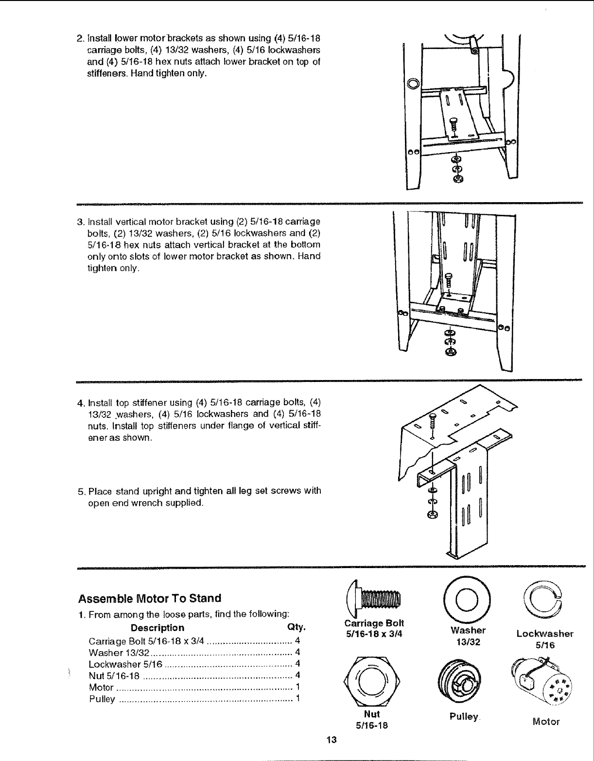
2. Install lower motorbrackets as shown using (4) 5/16-18
carriage bolts, (4) 13/32 washers, (4) 5/16 Iockwashers
and (4) 5/16-18 hex nuts attach lower bracket on top of
stiffeners. Hand tighten only.
3. Install vertical motor bracket using (2) 5/16-18 carriage
bolts, (2) 13/32 washers, (2) 5/16 Iockwashers and (2)
5/16-18 hex nuts attach vertical bracket at the bottom
only onto slots of lower motor bracket as shown. Hanrt
tighten only.
4. install top stiffener using (4) 5/16-18 carriage bolts, (4)
13/32 washers, (4) 5/16 tockwashers and (4) 5/16-18
nuts. Install top stiffeners under flange of vertical stiff-
ener as shown.
5. Place stand upright and tighten all leg set screws with
open end wrench supplied.
Assemble Motor To Stand
1. From among the loose parts, find the following:
Description Qty.
Carriage Bolt 5/16-18 x 3/4 ................................ 4
Washer 13/32 ..................................................... 4
Lockwasher 5/16 ................................................ 4
Nut 5/16-18 ........................................................ 4
Motor .................................................................. 1
Pulley .................................................................. 1
Carriage Bolt
5t16-18 x 3/4
Nut
5t16-18
13
Q
Washer
13132
Pulley.
©
Lockwasher
5/16
Motor
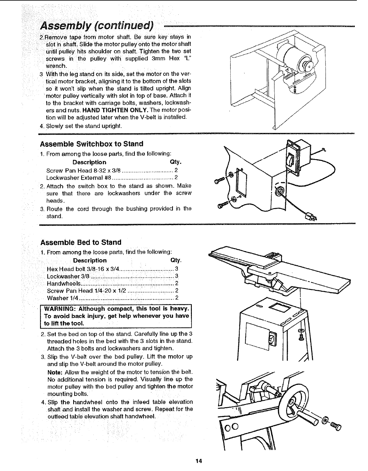
Until pulley hits shoulder on shaft. Tighten the two set
screws in:the pulley with supplied 3ram Hex "L"
i wrench.
i
3With the leg stand on its side, set the motor on the ver-
' tical motor bracket, aligning it to the bottom of the slots
so it won't Slip when the stand is tilted upright. Align
motor pulley vertically with slot in top of base. Attach it
to the bracket with carriage bolts, washers, Iockwash-
ers and nuts. HAND TIGHTEN ONLY. The motor posi-
tion will be adjusted later when the V-belt is installed.
4, Slowly set the stand upright.
Assemble Switchbox to Stand
1. From among the loose parts, find the following:
Description Qty.
Screw Pan Head 8-32 x 3/8 ............................... 2
Lockwasher External #8 ..................................... 2
2. Attach the switch box to the stand as shown, Make
sure that there are Iockwashers under the screw
heads.
3. Route the cord through the bushing provided in the
stand.
liH
Assemble Bed to Stand
1. From among the loose parts, find the following:
Qty.
Rex Head b01t 3/8-16 x 3/4 ............. i!.......:.,...i.,... 3
:LOckwasher3/8..;.,_. ......_......... ;_._....-. _;3
Screw Pan Head 114-20x 11/2........ .................... 2
: Washer 1/4 ,..; ..... i:,.i.,.,...; ....... _.:;!..................... 2
WARNING: Although compact, this tool is heavy. I
To avoid back injury, get help whenever you have I
to lift the tool.
2. Set the bed on top of the stand. Carefully line upthe 3
threaded holes in the bed with the 3 slots in the stand.
Attach the 3 bolts and Iockwashers and tighten.
3. Slip the Vzbelt over the bed pulley. Lift the motor up
and slip the V-belt around the motor pulley.
Note: Allow the weight of the motor to tension the belt.
No additional tension is required. Visually line up the
motor pulley with the bed pulley and tighten the motor
mounting bolts.
4. Siip the handwheel onto the infeed table elevation
shaft and install the washer and screw. Repeat for the
outfeed table elevation shaft handwheel.
14
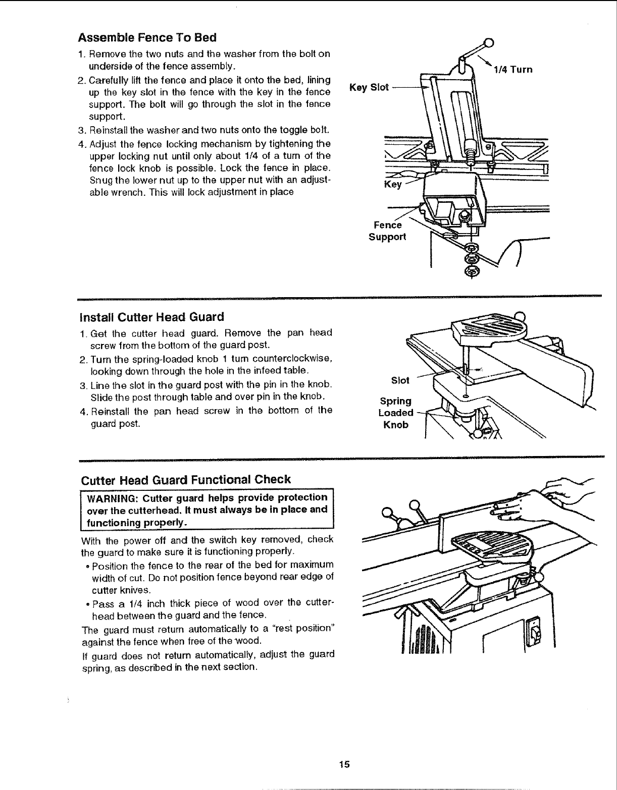
Assemble Fence To Bed
1. Remove the two nuts and the washer from the bolt on
underside of the fence assemMy,
2, Carefully lift the fence and place it onto the bed, lining
up the key slot in the fence with the key in the fence
support. The bolt will go through the slot in the fence
support.
3, Reinstall the washer and two nuts onto the toggle bolt.
4. Adjust the fence locking mechanism by tightening the
upper locking nut until only about 1/4 of a turn of the
fence lock knob is possible. Lock the fence in place.
Snug the lower nut up to the upper nut with an adjust-
able wrench. This will lock adjustment in place
Key Slot
Key
\_" 114Turn
Fence
Support
install Cutter Head Guard
1. Get the cutter head guard. Remove the pan head
screw from the bottom of the guard pest.
2. Turn the spring-loaded knob 1 turn counterclockwise,
looking down through the hole in the infeed table.
3. Line the slot in the guard post with the pin in the knob.
Slide the post through table and over pin in the knob,
4. Reinstall the pan head screw in the bottom of the
guard post.
Slot
Spring
Loaded
Knob
_L
Cutter Head Guard Functional Check
WARNING: Cutter guard helps provide protection
over the cutterhead, It must always be in place and !
functioning properly.
With the power off and the switch key removed, check
the guard to make sure it is functioning properly.
•Position the fence to the rear of the bed for maximum
width of cut. Do not positionfence beyond rear edge of
cutter knives.
.Pass a 1/4 inch thick piece of wood over the cutter-
head between the guard and the fence.
The guard must return automatically to a "rest position"
against the fence when free of the wood.
If guard does not return automatically, adjust the guard
spring, as described in the next section.
15
Assembly (continued)
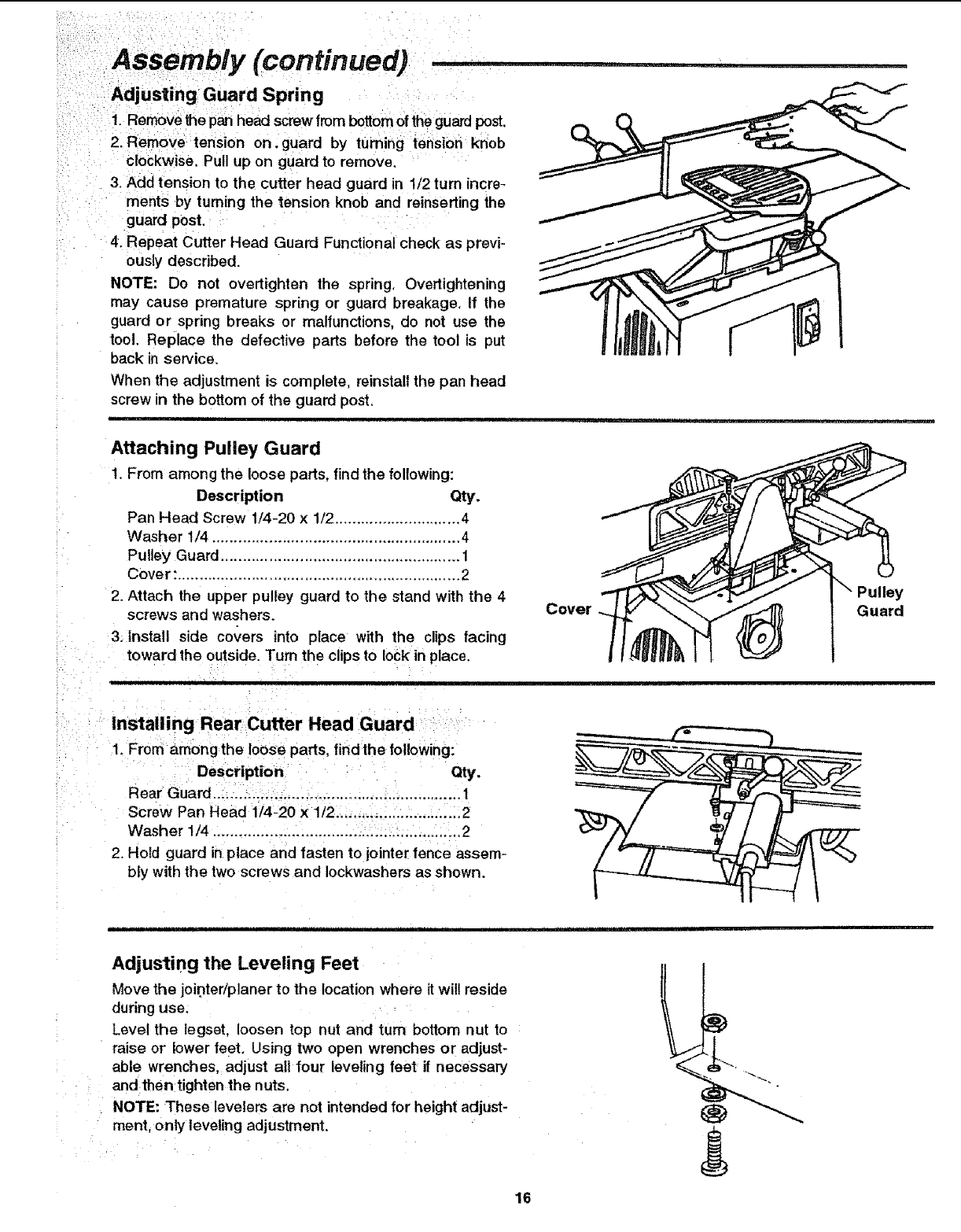
Adjusting Guard Spring
1. Remove the pan head screw from bottom of the guard post,
2. Remove tension on.guard by turning tension knob
clockwise. Pull up on guard to remove.
3, Add tension to the cutter head guard in 1/2 turn incre-
ments by turning the tension knob and reinserting the
guard post.
4. Repeat Cutter Head Guard Functional check as previ-
ously described.
NOTE: Do not overtighten the spring, Overtightening
may cause premature spring or guard breakage, If the
guard or spring breaks or malfunctions, do not use the
tool. Replace the defective parts before the tool is put
back inservice.
When the adjustment is complete, reinstall the pan head
screw in the bottom of the guard post.
Attaching Pulley Guard
!. From among the loose parts, find the following:
Description Qty.
Pan Head Screw 1/4-20 x 1/2 ............................. 4
Washer 1/4 ......................................................... 4
Pulley Guard ....................................................... 1
Cover: ................................................................. 2
2. Attach the upper pulley guard to the stand with the 4
screws and washers.
3. Install side covers into place with the clips facing
toward the outside. Turn the clips to lock in place.
Cover
Installing Rear Cutter Head Guard
1. From among the loose parts, find the following:
Description Qty.
Rear Guard ......................................................... t
Screw Pan Head 1/4-20 x 1/2 ...................... :...... 2
Washer 1/4 ......................................................... 2
2. Hold guard in place and fasten to jointer fence assem-
bly with the two screws and Iockwashers as shown.
Pulley
Guard
Adjusting the Leveling Feet
Move the jointer/planer to the location where it wil! reside
during use.
Level the legset, loosen top nut and turn bottom nut to
raise or lower feet. Using two open wrenches or adjust-
able wrenches, adjust all four leveling feet if necessary
and then tighten the nuts.
NOTE: These levelers are not intended for height adjust-
ment, only leveling adjustment,
16
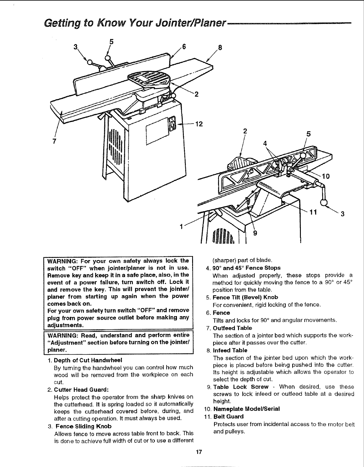
Getting to Know Your Jointer/Planer
5
3//8
4
5
11
WARNING: For your own safety always lock the
switch "OFF" when jointertplaner is not in use.
Remove key and keep it in a safe place, also, in the
event of a power failure, turn switch off. Lock it
and remove the key. This will prevent the jointed
planer from starting up again when the power
comes back on.
For your own safety turn switch "OFF" and remove
plug from power source outlet before making any
adjustments.
WARNING: Read, understand and perform entire
"Adjustment" section before turning on the jointed
planer.
1. Depth of Cut Handwheei
By turning the handwheel you can control how much
wood will be removed from the workpiece on each
cut.
2. Cutter Head Guard:
Helps protect the operator from the sharp knives on
the cutterhead, It is spring loaded so it automatically
keeps the cutterhead covered before, during, and
after a cutting operation. It must always be used.
3. Fence Sliding Knob
Allows fence to move across table front to back. This
is done to achieve fult width of cut orto use a different
(sharper) part of blade.
4.90 ° and 45°Fence Stops
When adjusted properly, these stops provide a
method for quickly moving the fence to a 90° or 45 °
position from the tab.le.
5. Fence Tilt (Bevel) Knob
For convenient, rigid locking of the fence.
6. Fence
Tilts and locks for 90° and angular movements.
7. Ouffeed Table
The section of a jointer bed which supports the work-
piece after it passes over the cutter.
8, Infeed Table
The section of the jointer bed upon which the work-
piece is placed before being pushed into the cutter.
Its height is adjustable which allows the operator to
select the depth of cut.
9. Table Lock Screw - When desired, use these
screws to lock infeed or outfeed table at a desired
height.
Nameplate Model/Serial
Belt Guard
Protects user from incidental access to the motor be_t
and pulleys.
10,
11.
17
i¸¸!:/ _ i i¸ i :.i _:
!!iii!!iill_ill!i!! i _ /i!i _ ! i
t-----"---"-
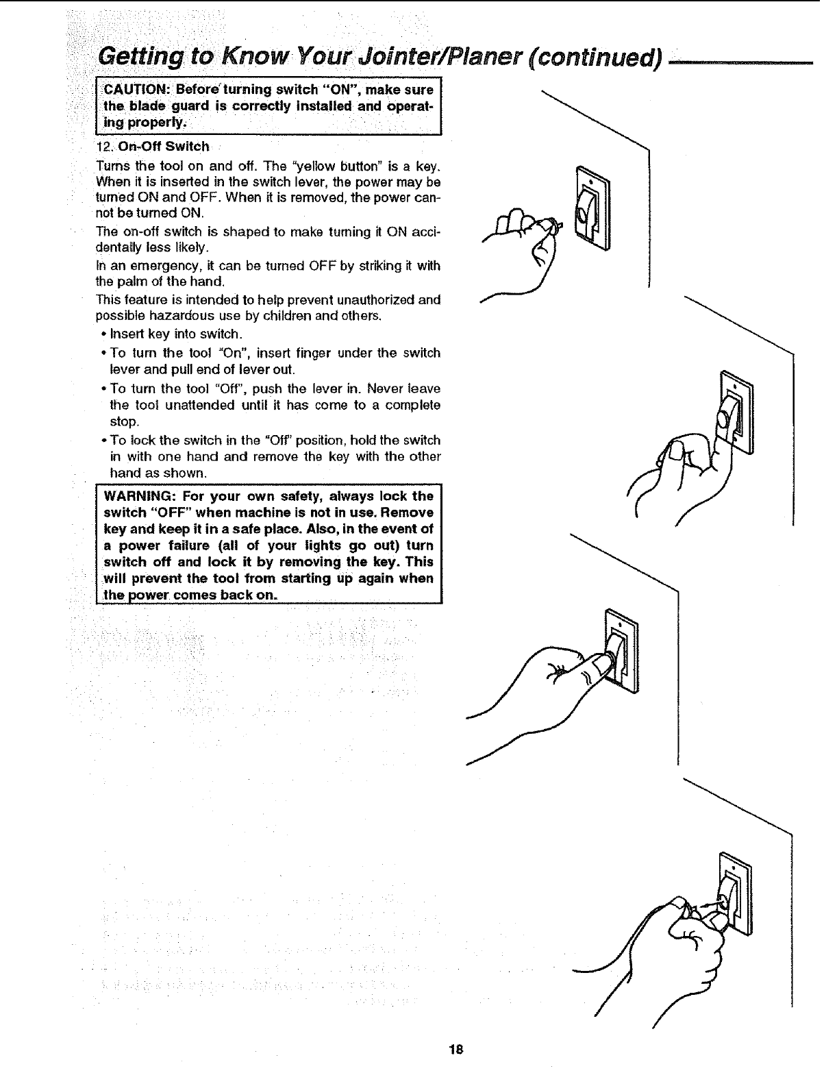
ICAUTION: Beforeturning switch "ON", make sure
I theblade guard is correctly installed and operat-
'ling properly.
12. On-Off Switch
Turns the tool on and off. The "yellow button" is akey.
When it is inserted in the switch lever, the power may be
turned ON and OFF. When it is removed, the power can-
not be turned ON.
The on-off switch is shaped to make turning it ON acci-
dentally less likely
In an emergency, it can be turned OFF by striking it with
the palm of the hand
This feature is intended to help prevent unauthorized and
possible hazardous use by children and others
• Insert key into switch
• To turn the tool "On", insert finger under the switch
lever and pull end of lever out
• To turn the tool "Off', push the lever in Never leave
the tool unattended until it has come to a complete
stop
• To lock the switch in the "Off' position, hold the switch
in with one hand and remove the key with the other
hand as shown
WARNING: For your own safety, always lock the
switch "OFF" when machine is not in use. Remove
key and keep it in a safe place. Also, in the event of
a power failure (all of your lights go out) turn
switch off and lock it by removing the key. This
will prevent the tool from starting up again when
the power 'comes back On.
(continued)
18
Alignments .........................
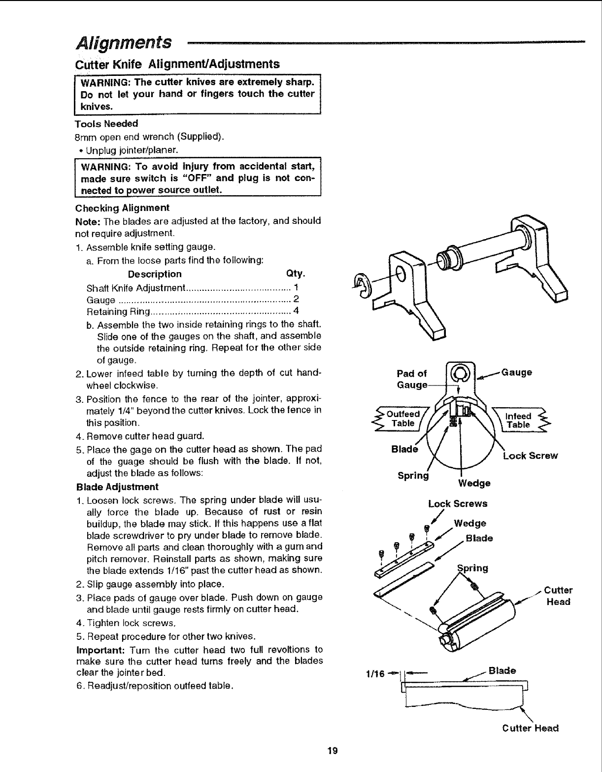
Cutter Knife Alignment/Adjustments
IWARNING: The cutter knives are extremely sharp. I
Do not let your hand or fingers touch the cutter fknives.
Tools Needed
8ram open end wrench (Supplied).
- Unplug jointer/planer,
IWARNING: To avoid injury from accidental start, ]
made sure switch is "OFF" and plug is not con- I
nected to power source outlet.
Checking Alignment
Note: The blades are adjusted at the factory, and should
not require adjustment.
1. Assemble knife setting gauge.
a, From the loose parts find the following:
Description Qty.
Shaft Knife Adjustment ....................................... 1
Gauge ................................................................ 2
Retaining Ring .................................................... 4
b. Assemble the two inside retaining rings to the shaft.
Slide one of the gauges on the shaft, and assemble
the outside retaining ring. Repeat for the other side
of gauge.
2. Lower infeed table by turning the depth of cut hand-
wheel clockwise.
3. Position the fence to the rear of the jointer, approxi-
mately 1/4" beyond the cutter knives. Lock the fence in
this pasit[on.
4. Remove cutter head guard.
5. Place the gage on the cutter head as shown. The pad
of the guage should be flush with the blade. If not,
adjust the blade as follows:
Blade Adjustment
1. Loosen lock screws. The spring under blade will usu-
ally force the blade up. Because of rust or resin
buildup, the blade may stick. If this happens use aflat
blade screwdriver to pry under blade to remove blade.
Remove all parts and clean thoroughly with a gum and
pitch remover. Reinstall parts as shown, making sure
the blade extends 1/16" past the cutter head as shown.
2. Slip gauge assembly into place.
3. Place pads of gauge over blade. Push down on gauge
and blade until gauge rests firmly on cutter head.
4. Tighten lock screws,
5. Repeat procedure for other two knives.
Important: Turn the cutter head two full revoltions to
make sure the cutter head turns freely and the blades
clear the jointe r bed.
6. Readjust/reposition outfeed table.
Pad of
Gnu
Blade Lock Screw
Spring Wedge
Lock Screws
Wedge
_ _____Blade
"_._. "-___ Head
1/16 -=" _ Blade
C utter Head
19
Alignments (continued)
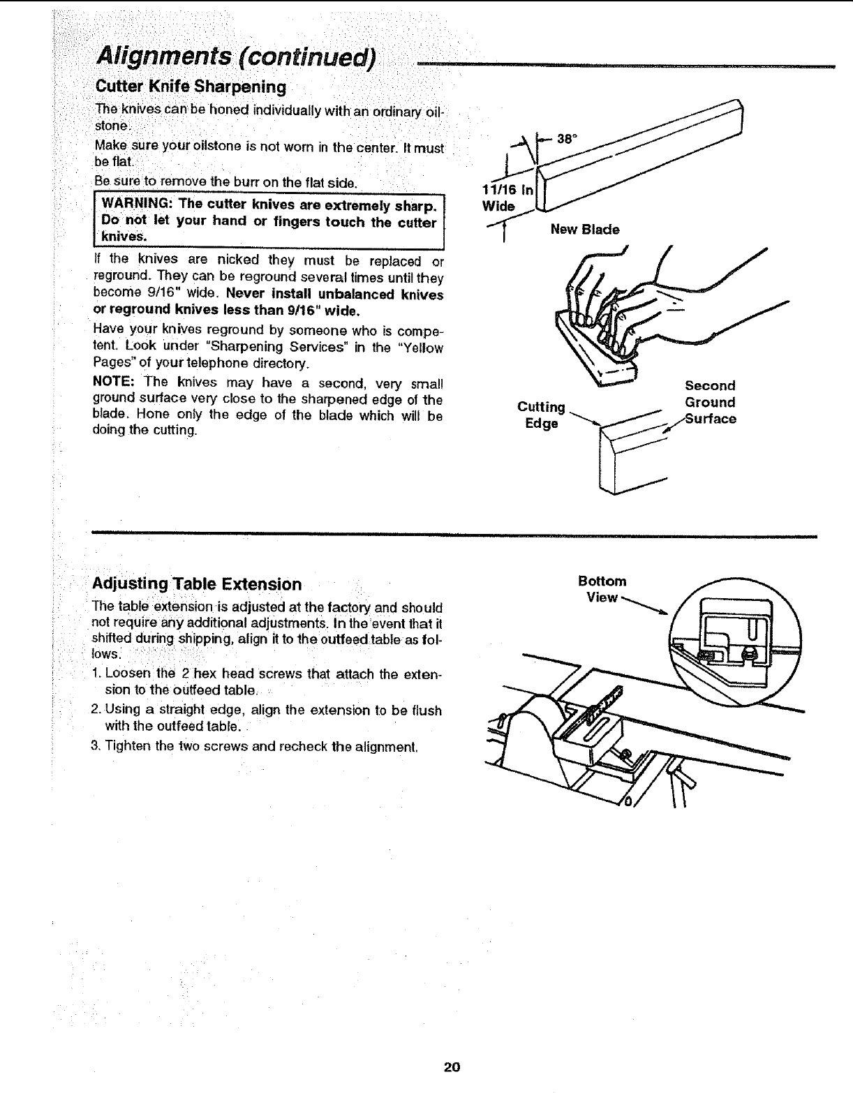
Cutter Knife Sharpening
The knives can be honed individually with an ordinaryoil-
stone.
Make sure your oilstone is not worn in the center. It must
be flat.
Be sure to remove the burr on the flat side.
WARNING: The cutter knives are extremely sharp. I
Do not let your hand or fingers touch the cutter f
knives.
if the knives are nicked they must be replaced or
reground. They can be reground several times until they
become 9/16" wide. Never install unbalanced knives
or reground knives less than 9/16" wide.
Have your knives reground by someone who is compe-
tent, Look under "Sharpening Services" in the "Yellow
Pages" of your telephone directory,
NOTE: The knives may have a second, very small
ground surface very close to the sharpened edge of the
blade, Hone only the edge of the blade which wii be
doing the cutting.
11/16 In
Wide
New Blade
Cutti
Edge
Second
Ground
i1,1,111,11 ii iii ii ! . Lil!l ii !lL I ILLI
Adjusting Table Extension
The table extension is adjusted at the factory and should
not require any additional adjustments In the event that it
shifted during shipping, align itto the outfeed table as fol-
lows.
1. Loosen the 2hex head screws that attach the exten-
sion to the ouffeed table.
2. Using a straight edge, align the extension to be flush
with the outfeed table.
3. Tighten the two screws and recheck the alignment.
2O
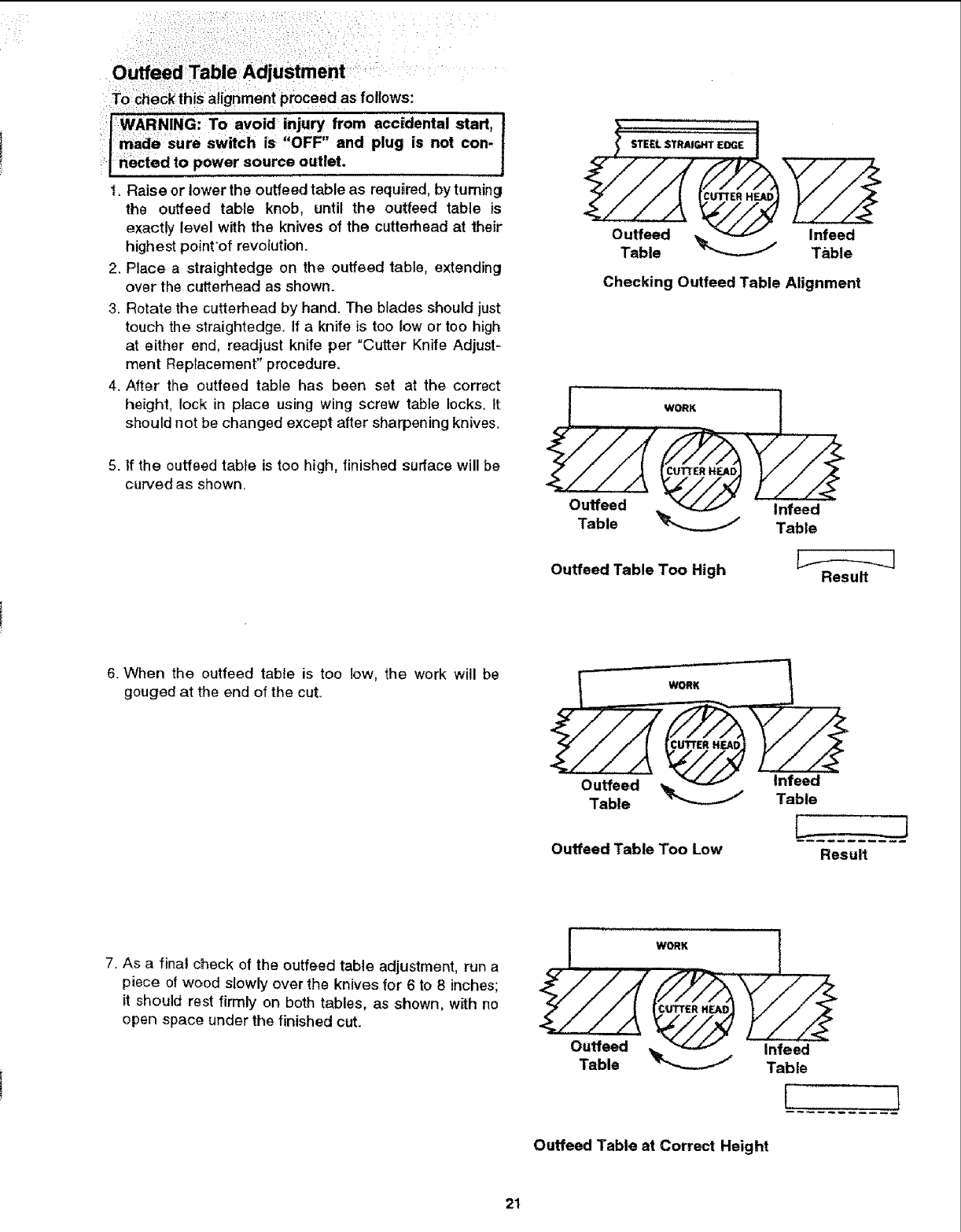
Outfeed TableAdjustment
To checkthis alignment proceed as follows:
WARNING: To avoid injury from accidental start,
made sure switch is "OFF" and plug is not con-
nected to power source outlet.
I. Raise or lower the outfeed table as required, by turning
the ouffeed table knob, until the outfeed table is
exactly level with the knives of the cutterhead at their
highest pointof revolution.
2. Place a straightedge on the outfeed fable, extending
over the cutterhead as shown.
3. Rotate the cutterhead by hand. The blades should just
teuch the straightedge. If a knife is too low or too high
at either end, readjust knife per "Cutter Knife Adjust-
ment Replacement" procedure.
4. After the outfeed table has been set at the correct
height, lock in place using wing screw table locks. It
should not be changed except after sharpening knives,
5. If the outfeed table is too high, finished surface will be
curved as shown.
.a//A '_.//-4 f //._
Checking Outfeed Table Alignment
J.. ,-_ I
%,:° ';'o;:
Outfeed Table Too High Result
6. When the outfeed table is too low, the work will be
gouged at the end of the cut. WORK
L__J
Ouffeed Table Too Low Result
7. As a final check of the outfeed table adjustment, run a
piece of wood slowly over the knives for 6 to 8 inches;
it should rest firmly on both tables, as shown, with no
open space under the finished cut.
IWORK I
I
Outfeed Table at Correct Height
21
Alignments (continued)
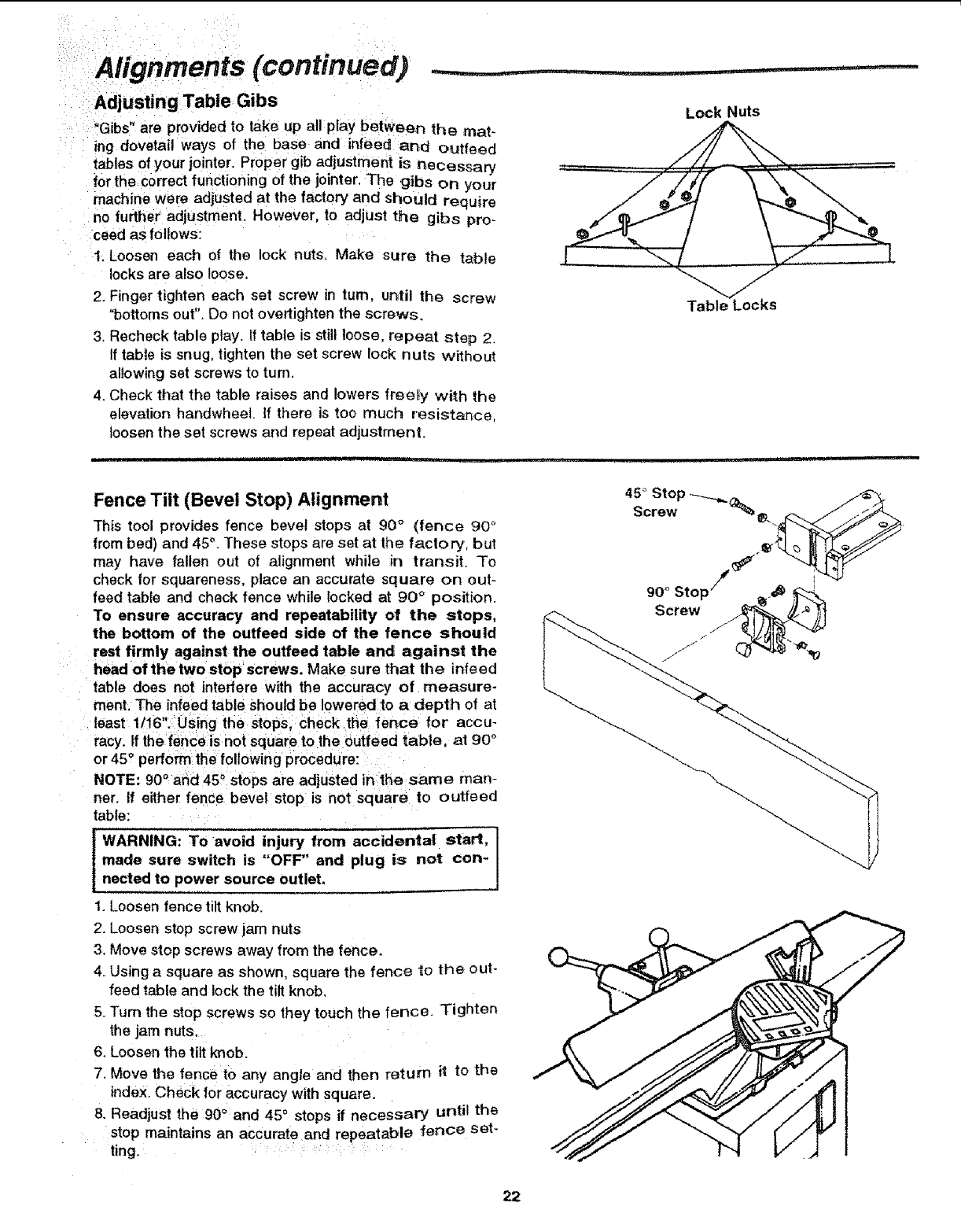
Adjusting Table Gibs
"Gibs" are provided to take up all play between the mat-
ing dovetail ways of the base and infeed and outfeed
tables of your jointer. Proper gib adjustment is necessary
for the correct functioning of the jointer, The gibs on your
machine were adjusted at the factory and should require
no further adjustment. However, to adjust the gibs pro-
teed as follows:
!. Loosen each of the lock nuts, Make sure the table
locks are also loose,
2. Finger tighten each set screw in turn, until the screw
"bottoms out". Do not overtighten the screws.
3, Recheck table play. If table is still loose, repeat step 2.
If table is snug, tighten the set screw lock nuts without
allowing set screws to turn.
4. Check that the table raises and lowers freel_y with the
elevation handwheeL If there is too much resistance,
loosen the set screws and repeat adjustment.
Lock Nuts
Table Locks
Fence Tilt (Bevel Stop) Alignment
This tool provides fence bevel stops at 90° (fence 90 _'
from bed) and 45°.These stops are set at the factory, but
may have fallen out of alignment while in transit. To
check for squareness, place an accurate square on out-
feed table and check fence while locked at 90 °position.
To ensure accuracy and repeatability of the stops,
the bottom of the outfeed side of the fence should
rest firmly aglainst the ouffeed table and against the
head of the two stop screws. Make sure that the infeed
table does not interfere with the accuracy of measure-
ment. The infeed table Should be lowered :to a depth of at
least 11!6' Using the stops, Check the fence for accu-
racy. If the fence is not square to the outfeed table, at 90 °
or 45_ perfo_ the following procedure:
NOTE: 90°and 45_ Stops are adjusted in the same man-
ner. If either fence bevel stop is not square to outfeed
table: ....
'"W'RNING: To avoid !nju.r_,,from acc'd'enta' start' !
made sure switch is OFF and plug is not con_
nected to power source outlet, ..
1. Loosen fence tilt knob.
2. Loosen stop screw jam nuts
3, Move stop screws away from the fence.
4. Using a square as shown, square the fence to the out-
feed table and lock the tilt knob,
5. Turn the stop screws so they touch the fence. Tighten
the jam nuts,
6. Loosen the tilt knob.
7. Move the fence to any angle and then return H to the
indeX.Check for accuracy with square.
8. Readjust the 90°and 45°stops if necessary until the
stop maintains an accurate and repeatable fence set-
ting.
45°Stop
Screw _
22

Safety instructions for Basic Jointer/Planer Operation
'Before Each Use:
InSpect your jointer/planer.
.WARNING: The 2-1/2 inch jointer/pianer pulley and
the 3-112 inch motor pulley furnished will run the
cutter head at about 5000 RPM when used with a
3450 RPM motor. Use of different types of pulleys
or motors will change this speed and could cause
jamming, binding, kickback, thrown blades or
other dangers.
•If any part is missing, bent or broken inany way, or any
electrical part does not work properly, tum the jointed
planer off and unplug the jointer/planer,
• Replace damaged or missing parts before using the
jointer/plane r again.
= Make sure the cutter head turns in the right direction.
.,.11111,, ii
To Avoid Injury From Jams, Slips Or Thrown
,Use this jointer/planer to cut only wood.
•Plan your hand placement so your fingers wil_lnot be
anywhere a sudden slip could cause them to slide or
fall into the cutter head. When using only one hold-
down/push-block to feed the wood, do not put your
other hand on the jointer/planer, workpiece, or hold-
down/push-block.
• Make sure the clamps and locks are tight and there is
not excessive play in any parts.
•To avoid injury from thrown pieces, make sure the
blades are properly installed and the cutter blade
wedge screws are tight.
• Adjust the depth of cut to between 1/32 and 1/16 of an
inch for best results in most operations. A deep cut
makes feeding the wood harder and can cause the
wood to kickback. To be sure you will make a depth of
cut you planned, always lower the infeed table slightly
farther than you wanted. Then, raise the table to the
desired depth.
Plan Ahead to Protect Your Eyes, Hands, Face and Ears
The top should move toward the infeed table, Call your
Sears Service Department for help ff the cutter head
turns the wrong way.
-Keep JointeriPtaner interior, free of wood chips and
dust buildup around motor and switch box.
• Keep blades sharp. Dull or nicked blades tend to
"pound" and chew at the wood, causing kickbacks.
o Make sure the cutter guard works properly. With the
switch off and key removed, pull the cutter.guard open
and let go. If the guard doesn't smoothly swing closed,
contact Sears Service.
° To avoid injury from accidental starting, always turn
switch off, remove switch key and unplug jointer_'planer
before installing or removing any blade, accessory or
attachment or making any adjustments.
iiii ............
Pieces (Kickbacks Or Throwbacks):
o Use The Right Tool. Don't force tool or attachment to
do a job it was not designed for.
Inspect your work area.
•Keep workarea clean,
• Cluttered areas and benches invite accidents. Floor
must not be slippery from wax or sawdust,
o To avoid bums or other fire damage, never use the
jointer/planer near flammable liquids, vapors or gases.
° Before using the jointer/planer, ct_ar the table of all
objects not needed to teed the workpiece.
• To avoid injury, don't do layout, assembly, or setup
work on the jointer!planer.
Plan your work
•Before trying a new or little used operation, carefully
plan your hand placement, Make sure you have proper
hold-down!push-blocks, jigs, fixtures, stops, etc. ready
to use.
-To avoid injury Item unsafe accessories, use only rec-
ommended accessories.
Dress for safety
•Plan ahead to protect your eyes, hands, face, ears.
° Do not wear loose clothing, gloves, neckties or jewelry
(rings, wrist watches). They can get caught and draw
you into moving parts.
* Wear nonslipfootwear.
•Tie back long hair.
° Roll long sleeves above the elbow.
o Noise levels vary widely. To avoid possible hearing
damage, wear ear plugs or muffs when using jointeri
planer for hours at a time.
oAny jointer/planer can throw foreign objects into the
eyes. This can result in permanent eye damage. Wear
safety goggles (not glasses) that comply with ANSI
7_87.1(shown on package), Everyday eyeglasses have
only impact resistant lenses. They are not safety
glasses. Safety goggles are available at Sears retail
stores. Glasses or goggles not in compliance with
ANSI Z87.1 could seriously hurt you when they break.
•For dusty operations, wear a dust mask along with
safety goggles.
Inspect your workpiece.
*Make sure there are no nails or foreign objects in the
part of the workpiece to be cut.
Plan your cut.
•Small or thin workpieces car= kickback when they tip
over on the tables or into the cutter head. To avoic_
head contact or workpiece kickback:
- Never joint, plane or bevel workpieces shorter than
12 inches.
23
Safety instructions for Basic Jointer/Planer Operation (continued)
- When jointing orbeveling:
-Never joint or bevel workpieces less than 3/4 inch
wide or 1/4 inch thick.
- Always use the hold-down/push-blocks when j0inting
or beveling wood narrower than 3 inches.
-When rabbeting, always make cuts in !/8" incre-
and its supports.
-Use extra caution with large, very small or awkward
workpieces.
•Use extra supports (tables, saw horses, blocks, etc.) if
your workpiece is hard to hold down to the table. Never
use another person as additional support or to help
ments or less.
•When planing:
-Never plane wood thinner than 1/2 inch,
-Always use hold-down/push-blocks when
wood thinner than 3 inches. planing
feed, support or pull the workpiece,
•Never cut more than one workpiece at a time.
- Never turn your table jointedplaner "ON" before clear-
ing everything except the workpiece and related sup-
port devices off the table.
-Never cut Freehand, Guide your workpiece solidly
against the fence and table top.
- Make sure there's no debris between the workpiece
Hit i
Whenever Jointer/Planer Is Running:
WARNING: Don't allow familiarity (gained from fre-
quent use of your jointer/planer) cause acareless
mistake. Always remember that a careless fraction
of a second is enough to cause a severe injury.
Keep Children Away,
•Keep all visitors a safe distance from the jointer!planer.
•Make sure bystanders are clear of the jointer/planer
and workpiece,
•Before actually cutting with the jointer/ptaner, let it run
for a while. If it makes an unfamiliar noise or vibrates,
stop immediately. Turn the jointer/ptaner off. Unplug
the jointeripianer, Do not restart until finding and cor-
recting the problem.
Don't Force Tool,
•Feed the workpiece into the jointer/planer only fast
enough to let the tool cut without bogging down or
Avoid Accidental Starting.
•Make sure switch is "OFF" before plugging jointer/_
planer into apower outlet.
binding.
Before freeing jammed material,
• Turn switch "OFF'.
°Wait for all moving parts to stop.
•Unplug the jointer/planer.
•Check blade, spreader and fence for proper alignment
before starting again_
Before Leaving the jointer/planer.
• Turn the jointer/planer off,
• Wait for }ointer/planer to come to a complete stop.
• Unplug the jointer/ptaner.
•Make workshop child-proof. Lock the shop. Disconnect
master switches. Remove the yellow switch key. Store
it away from children and others not qualified to use
the tool.
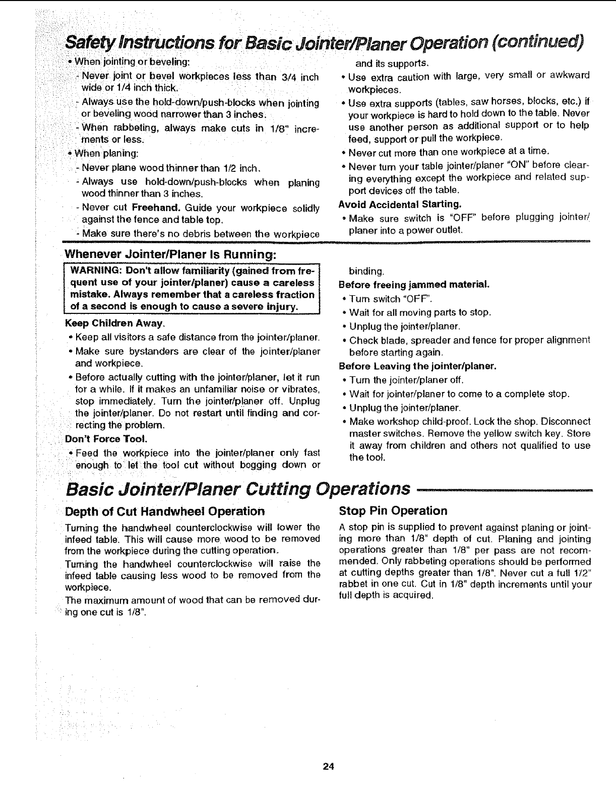
Basic Jointer/Pianer Cutting Operations
Depth of Cut Handwheel Operation
Turning the handwheel counterclockwise will _ower the
infeed table. This will cause more wood to be removed
from the workpiece during the cutting operation.
"Fuming the handwheel counterclockwise will raise the
infeed table causing less wood to be removed from the
workpiece.
The maximum amount of wood that can be removed dur-
ing one cut is 1/8".
Stop Pin Operation
A stop pin is supplied to prevent against planing or joint-
ing more than 1/8" depth of cut. Planing and jointing
operations greater than 1/8" per pass are not recom-
mended. Only rabbeting operations should be performed
at cutting depths greater than 1/8". Never cut a fult 1/2"
rabbet in one cut. Cut in 1/8" depth increments until your
ful! depth is acquired.
24
Feeding the Workplace
Hold the board firmly down on both tables and against
the f_nce. Keep fingers c_osetogelher. Feed the board at
a continuous even rate of speed until the cut is made
along the entire length of the board. Any hesitation or
stopping could cause a "step" to be cut on the edge of the
board which would cause the board to ride up onthe out-
feed table resulting in a "crooked" edge on the hoard
As the trailing hand passes ever the cutterhead, remove
the leading hand, Continue feeding while placing the
leading hand behind the trailing hand, Continue feeding
in this manner "hand over hand "', until the entire length of
the board is cut. As soon as enough of the workplace has
been cut to do so, put pressure over the cutterhead
and ouffeed table.
Do not feed too fast. A slow steady rate of feed pro-
duces a smooth accurate cut, Feeding too fast causes a
"rippled" cut, makes it difficult to guide the workpiece
accurately, and coutd be dangerous.
NOTE: Wood chips may accumulate inside the iointeri
planer. Periodically clean out the chips from the interiorof
the jo inter/planer.
NOTE: Before cleaning wood chips.
•Turn switch "OFF".
° Wait for all moving parts to stop.
• Unplug the jointer/p{aner.
i=1, pl! =,L ill i
Feed with the grain whenever possible. If the nature ol
the workplace is such that it must be fed against the
grain, take very light cuts and feed slowly.
Rotation
With the Grain
Planing
Planing is removing wood from the widest surface or face
of a board so as to make it flat and smooth.
Planing on a jointer will not necessarily make the face
that is planed square or p&ratlel to any other surface.
Planing on a jointer only smooths and flattens If you are
planing and jointing a board, the planing operation should
be performed first. This allows the jointed edge to be cut
square to the face which was previously planed flat and
smooth,
25
Basic Jointer/Planer Cutting Operations (continued) .......... ,,.,, ,==
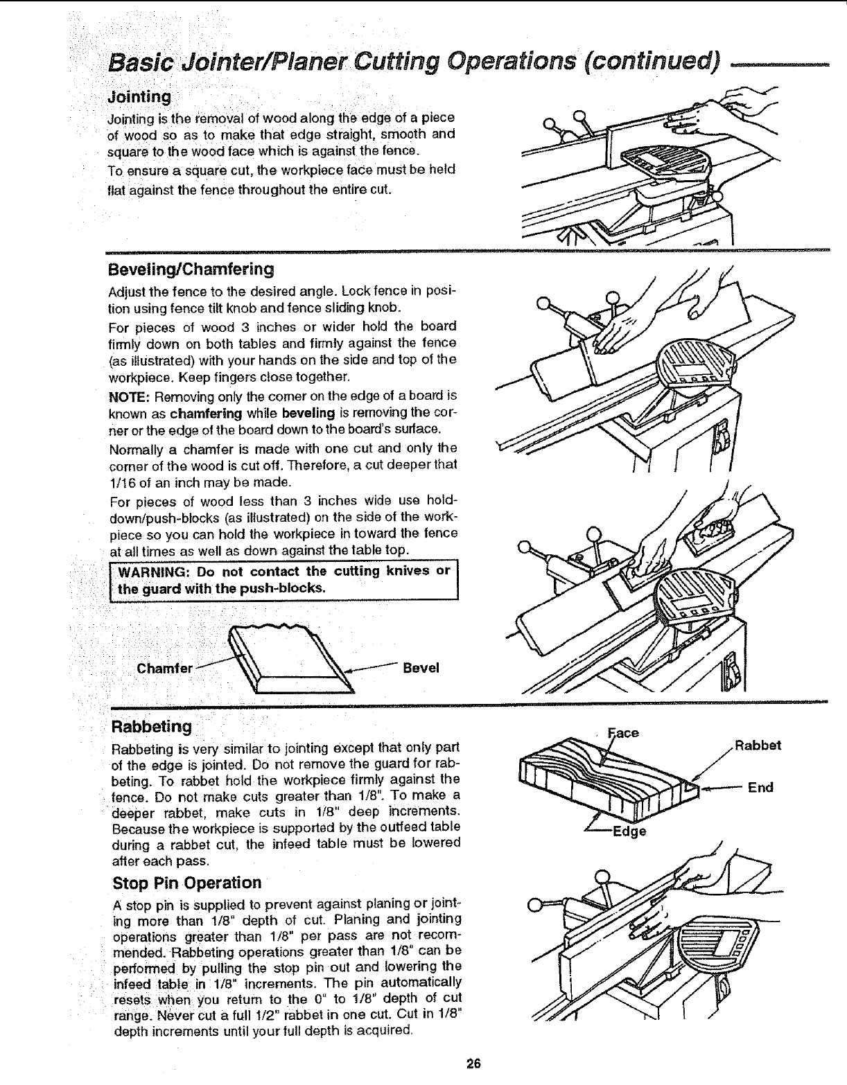
Jointing_ :: ,
Joiniing is the removal of wood along the edge'of a piece
Of wood so as to make that edge straight, smooth and
squal_e to the wood face which is against the fence.
To ensure a square cut, the workpiece face must be held
flat against the fence throughout the entire cut.
, 'l'lMr JJ I,II,,, HI1, _L
Beveling/Chamfering
Adjustthe fence to the desired angle. Lockfence in posi-
tion using fence tilt knob and fence sliding knob.
For pieces of wood 3inches or wider hold the board
firmly down on both tables and firmly against the fence
(as illustrated) with your hands on the side and top of the
workpiece. Keep fingers close together,
NOTE: Removing only the comer on the edge of a board is
known as chamfering while beveling is removing the cor-
ner orthe edge of the board down to the board's surface.
Normally a chamfer is made with one cut and only the
corner of the wood is cut off. Therefore, a cut deeper that
1/t6 of an inch may be made.
For pieces of wood less than 3 inches wide use hold-
down/push-blocks (as illustrated) on the side of the work-
piece so you can hold the workpiece in toward the fence
at all times as well as down against the table top.
WARNING: Do not contact the cutting knives or i
:lithe guard With the push-blocks. I
!,
:Chamfe Bevel
Rabbeting
Rabbeting is very similar to jointing except that only part
of the edge is jointed. Do not remove the guard for rab-
beting. To rabbet hold the workpiece firmly against the
fence. Do not make cuts greater than 1/8". To make a
•deeper rabbet, make cuts in 1/8" deep increments.
Because the workpiece is supported by the outfeed table
during arabbet cut, the infeed table must be lowered
after each pass.
Stop Pin Operation
Astep pin is supplied to prevent against planing or joint-
ing more than 1/8" depth o! cut. Planing and jointing
operations greater than 1/8' per pass are not, recom-
: mended. Rabbeting operations greater than 1/8 can be
performed by putiing the stop pin out and lowering the
:infeed tabte in:l/8 increments. The pin automatically
i resets Sen. you return to the 0" to 1/8" depth of cut
rangel N_ver Cut a full 1/2" rabbet in one cut. Cut in 1/8"
depth increments until your full depth is acquired.
ge
Rabbet
End
26
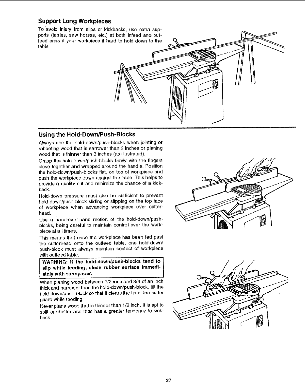
Support Long Workpieces
To avoid injury from slips or kickbacks, use extra sup-
ports (tables, saw horses, etc.) at both infeed and out-
feed ends if your workpiece if hard to hold down to the
table.
,,,,,, ,,,,,,,
Using the Hold-Down/Push-Blocks
Always use the hold_down/push-blocks when jointing or
rabbeting wood that is narrower than 3 inches or planing
wood that is thinner than 3 inches (as illustrated).
Grasp the hold-down/push-blocks firmly with the fingers
close together and wrapped around the handle. Position
the hold-down/push-blocks tlat, on top of workpiece and
push the workpiece down against the table. This helps to
provide a qualify cut and minimize the chance of a kick-
back.
Hold-down pressure must also be sufficient to prevent
held-down/push-block sliding or slipping on the top face
of workpiece when advancing workpiece over cutter-
head.
Use a I_and-over-hand motion of the hold-down/push-
blocks, being careful to maintain control over the work-
piece at all times.
This means that once the workpiece has been fed past
the cutterhead onto the outfeed table, one hold-down/
push-block must always maintain contact of workpiece
with outfeed table,
WARNING: If the hold-downlpush-blocks tend to I
slip while feeding, clean rubber surface immedi- I
ately with sandpaper,
When planing wood between 112 inch and 3/4 of an inch
thick and narrower than the hold-down/push-block, tilt the
hold-down/push-block so that it clears the tip of the cutter
guard while feeding.
Never ptane wood that is thinner than 1/2 inch. It is apt to
split or shatter and thus has a greater tendency to kick-
back.
27
Basic Jointer/Planer Cutting Operations (continued)
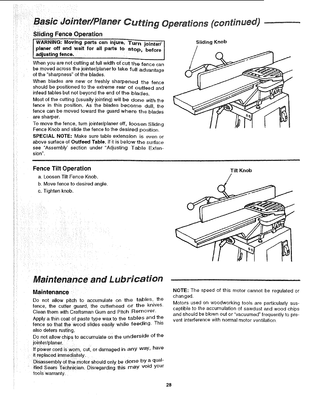
Sliding Fence Operation
WARNING: Moving parts can injure. Tu-rn jointed _ Sliding Knob
planer off and wait for all parts to stop, before Iadjusting ,fence,
When you are not cutting at futlwidth of cut the fence can
be moved across the jointer/planer to take full advantage
of the "sharpness" of the blades.
When blades are new or freshly sharpened the fence
should be positioned to the extreme rear of outfeed and
infeed tables but not beyond the end of the b_ades.
Most of the cutting (usually jointing) will be done with the
fence in this position. /ks the blades become dull, the
fence can be moved toward the guard where the blades
are sharper,
To move the fence, turn jointer/planer off. iloosen Sliding
Fence Knob and slide the fence to the desired position,
SPECIAL NOTE: Make sure table extension is even or
above surface of Outfeed Table. If it is below the surface
see "Assembly' sectior_ under "Adjusting Table Extem
sion"
Fence Tilt 0peration
a. Loosen Tilt Fence Knob.
b. Move fence to desired angle,
c. Tighten knob.
Tilt Knob
Maintenance and Lubrication
Maintenance
Do not allow pitch to accumulate on the tables, the
fence, the cutter guard, the cutterhead or the knives.
Clean them with Craftsman Gum and Pitch Remover.
Apply a thin coat of paste type wax to the tables and the
fence so that the wood slides easily while feeding. This
also deters resting.
Do not allow chips to accumulate on the underside of the
jointer/pfaner.
If power cord is worn, cut, or damaged in any way. have
it replaced immediately.
Disassembly of the motor should only be done by a qua!-
ified Sears Technician. Disregarding this may void your
tools warranty,
NOTE: The speed of this motor cannot be regulated or
changed.
Motors used on woodworking tools are particularly sus-
ceptible to the accumulation of sawdust and wood chips
and should be blown out or "vacuumed" frequently to pre-
vent interference with normal motor ventilation,
28
Lubrication
Unplug the joint__c_
start suddenly. You could be badSy hurt, j
The ball bearings inthis machine are packed with grease
at the factory, They required no further lubrication,
The following parts should be ,oiled occasionally with
SAE No. 20 or No. 30 engine oil.
1, Dovetail spacer and dovetail siide.
2. Elevation screw (first clean with gum and pitch
remover).
Sears Recommends the Following Accessories
Recommended Accessories
WARNING: To avoid injury from unsafe accesso-
ries, use only accessories shown on the recom-
mended accessories list in this manual,
Item Cat. No.
Cutter Blades ....................................................... 9-2293
Power Tool Know-How Handbook ...... 9-291 t4 & 29115
Sears may recommend other accessories not listed in
the manual, See your nearest Sears store for other
accessories.
Do not use any accessory unless you have received and
read complete instructions for its use.
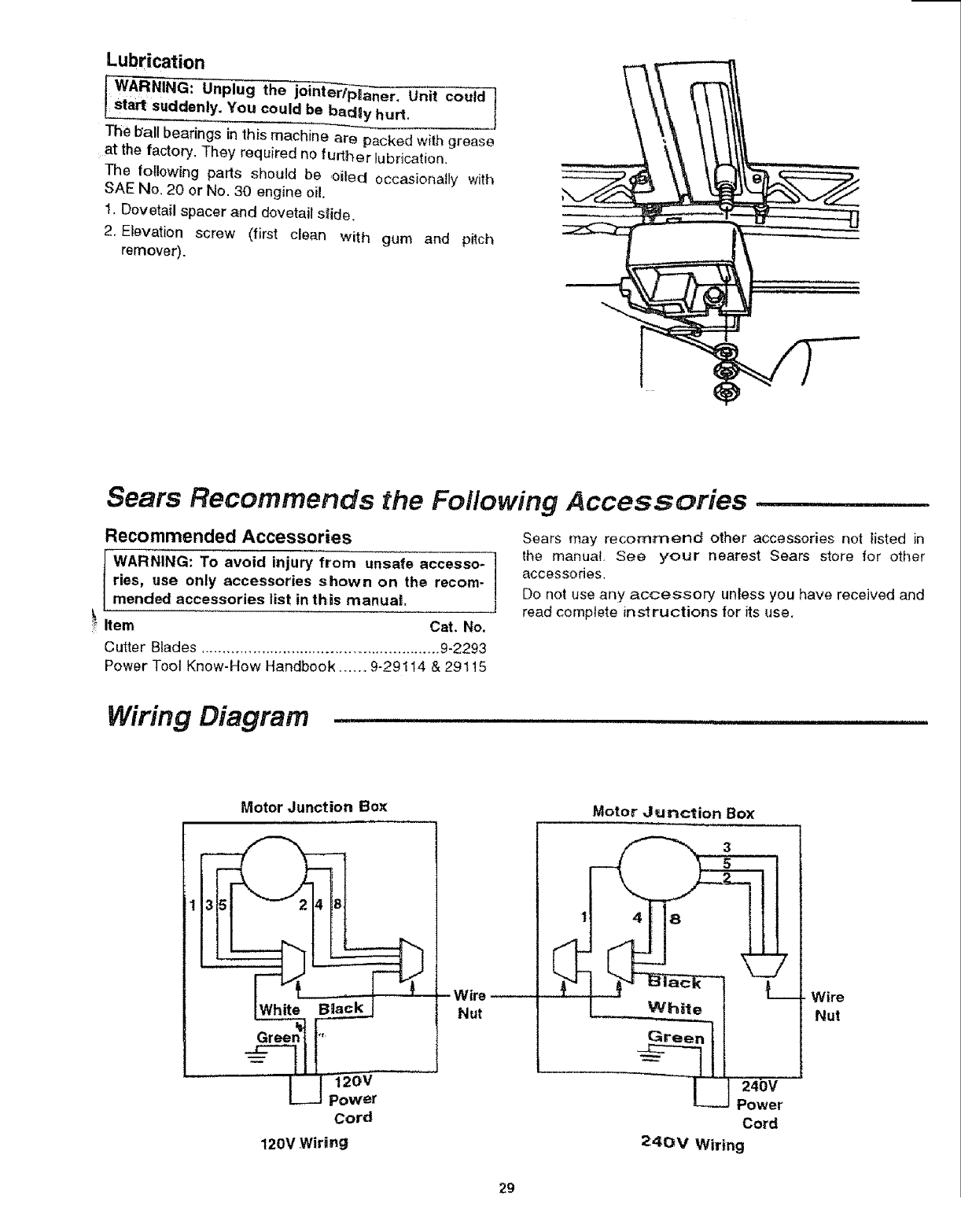
Wiring Diagram
Motor Junction Box
Cord
120V Wiring
Wire-
Nut
Motor Junction Box
-4
i
I
I
I
I
White
L
3
J24bY
Power
Cord
7
24OV Wiring
Wire
Nut
29
i::¸¸¸ i¸!:::://;/: :: ::::
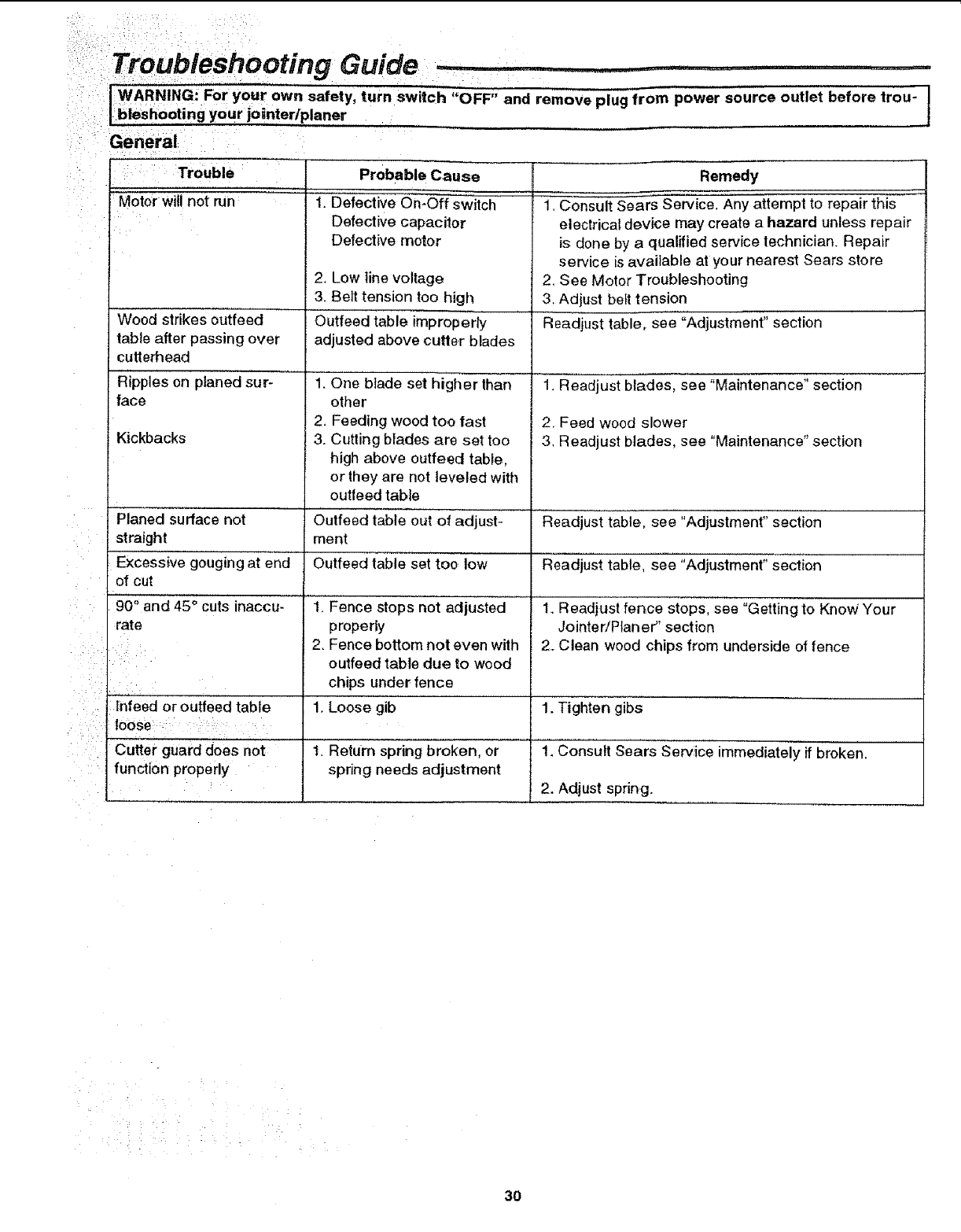
i:' Troubleshooting Guide
: ::: : : :
:' :1WARNING:" For your own safety turn switch "OFF" and remove plug from power source outlet before trou- J
I b!eshootingyour jointerlplaner I
:General
: Trouble
Motor will not run
;1
Wood strikes outfeed
table after passing over
cutterhead
Ripples on planed sur-
face
_i__ •
Kickbacks
Probable Cause
1. Def'ective On-Off switch
Defective capacilor
Defective motor
2. Low line voltage
3. Belt tension too high
Outfeed table improperly
adjusted above cutter blades
"' l":"'O'ne'b'ladeset higher than
ether
2. Feeding wood too fast
3. Cutting blades are set too
high above outfeed table,
or they are not leveled with
outfeed tabte
0utfeed table out Of adjust-
ment
Outfeed table set too low
Remedy
1. Consult Sears Serv'icel"Anyattempt to repair this
electrical device may create a hazard unless repair
is done by aqualified service technician. Repair
service is available at your nearest Sears store
2. See Motor Troubleshooting
3. Adjust belt tension
Readjust table, see "Adjustment" section
1. Readjust blades, see "Maintenance" section
2. Feed wood slower
3+ Readjust blades, see "Maintenance" section
-Planed surface not R'eadjust'tabie, see "Adjustment" seciion"
straight
Excessive gouging at end" Rea'dj'u'Sttable, see ;;Adjustment" section
of cut
90° and 45° cuts inaccu- 1. Fence stops not adjusted I. Readjust fence stopsi"see =Getting to Know Your
rate properly JointeriPlaner" section
2. Fence bottom not even with 2. Clean wood chips from underside of fence
: outfeed table due to wood
chips under fence
1. Loose gib 1. Tighten gibs
1. Return spring broken, or 1. Consult Sears Service immediately if broken.
spring needs adjustment
2. Adjust spring.
'Inieed or outfeed table
loose
Cutter guard does' not
function properly
3O
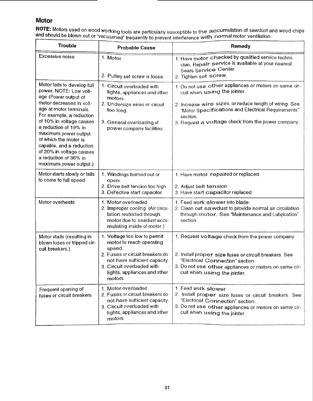
Motor
NOTE: Motors used on wood working tools are particularly susceptible to the accumulation of sawdust and wood chips
and_should be blown out or "vacuumed" frequently to prevent interference wi_t_ normal motor ventilation.
Trouble
Excessive noise
Motor fails to develop full
power. NOTE: Low volt-
age (Power output of
motor decreases in volt-
age at motor terminafs,
For example, a reduction
of 10% in voltage causes
a reduction of 19% in
maximum power output
of which the motor is
capable, and a reduction
of 20% in voltage causes
a reduction of 36% in
maximum power output.)
Motor starts slowly or fails
to come to full speed
Motor overheats
Motor stalls (resulting in
blown fuses or tripped cir-
cuit breakers.)
Frequent opening of
fuses or circuit breakers
Probable Cause
t. Motor
2. Pulley set screw is loose.
t. Circuit overloaded with
lights, appliances and other
motors.
2. LJndersize wires or circuit
too long,
3 General overloading of
power company facilities.
t.
2,
3.
t.
2.
Windings burned out or
open.
Drive belt tension too high.
Defective start capacitor
Motor overloaded
improper cooling (Air circu-
lation restricted through
motor due to sawdust accu_
mLflating inside of motor.)
!, Voltage too low to permit
motor to reach operating
speed.
2. Fuses or circuit breakers do
not have sufficient capacity.
3. Circuit overloaded with
lights, app liances and other
motors.
1, Motor overloaded
2. Fuses or circuit breakers do
not have sufficient capacity.
3. Circuit overloaded with
lights, appliances and other
motors.
Remedy
1, Have moto_ _checked by qualified service techni-
cian. Repair service is available at your nearest
Sears Service Center.
2, Tighten set screw.
1. Do not use other appliances or motors on same cir_
cuit when using the jointer.
2. Increase w_re sizes, or reduce length of wiring. See
"Motor Spec:ificat_ons and Electrical Requirements"
section,
3, Request a voltage check from the power company.
1. Have motor repaired or replaced
2. Adjust belt tension
3, Have start capacitor replaced
!. Feed work slower into blade.
2. Clean out sawdust to provide normal air circulation
through motor. See "Maintenance and Lubrication"
section.
1. Request voltage check from the power company
2. install proper size fuses or circuit breakers. See
"Electrical Connection" section
3. Do not use other appliances or motors on same cir-
cult when using the jointer.
1. Feed work slower
2. install proper size fuses or circuit breakers. See
"Electrical Connection" section
3. Do not use other appliances or motors on same cir-
cuit when using the jointen
31
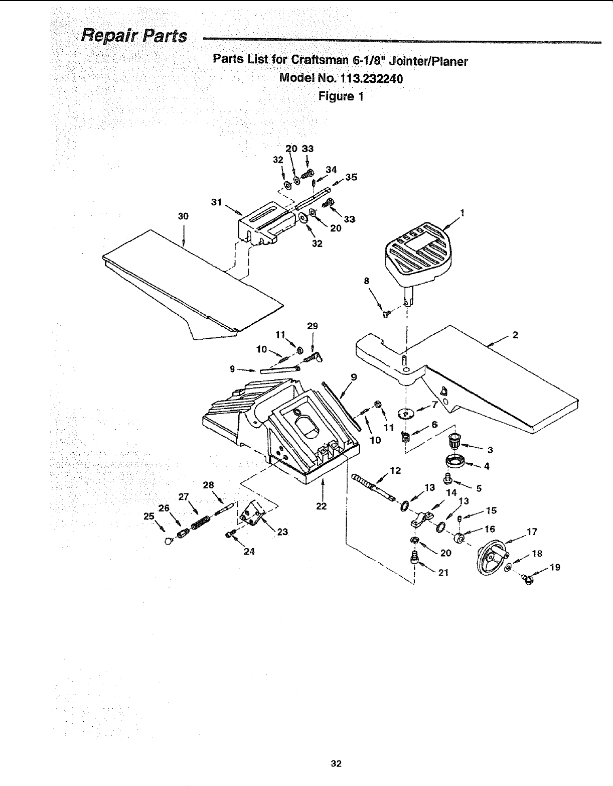
Repair Paris i,
Parts List for Craftsman 6-118" Jointer/Planer
Model No. 113.232240
Figure 1
ii_:_••i_il;i;::,¸¸_..... ;,:L7: '_i _
26
25
31
3O
28
_23
24
:N
32

Repair Parts
Parts List for Craftsman 6-118" Jointer/Pianer
Mode! No, 113.232240
Figure 1
Always order by Part Number -Not by Key Number
Key
No.
........ i,
2
3
4
5
6
7
8
9
10
11
12
13
14
15
16
17
18
Part No. Description
824919
824854
824867
824866
822495-1
824868
824865
816755-1
824856
160033-4
STD541025
824859
824860
824858
STD502503
824861
824918
STD551025
Guard Cutter
Table Infeed
Knob
Retainer Knob
* Screw Pan Hd 5/32 x 5/8
Spring
Retainer
Screw Pan Hd M5 x 0,8-10
Gib
Screw Set 1/4-20 x 1
* Nut Hex 1/4-20
Screw Elevation
Washer Brass
Clamp
* Screw Set 1/4420 x 3t8
Collar
Handwheet
* Washer 17/64 x 5/8 x 1/32
Standard hardware item, may be purchased locally
Key
No.
19
20
21
22
23
24 I
25
26
27
28
29
30
31
32
33
34
35
Part No. Description
STD512505
STD852008
141594-13
824853
824871
9421622
824875
824873
824872
824874
824857
824855
824862
824863
STD523712
813249-106
824864
SP5971
* Screw Pan Hd 1/4-20 x 1/2
* Lockwasher 8turn
Screw Cap 5/16_18 x 1-1/4
Base
Block Stop Pin
Screw Cap 5/16-18 x 3/4
Knob Plunger
Housing Plunger
Spring
Plunger
Screw Wing 1/4-20 × 1
Table Outfeed
Holder
Washer 3/8 x 20mm x 3mm
* Screw Hex Hd 3/8-16 x 1-!/4
Pin Roll 4ram x 20ram
Key
Owners Manual (Not Itls.)
33
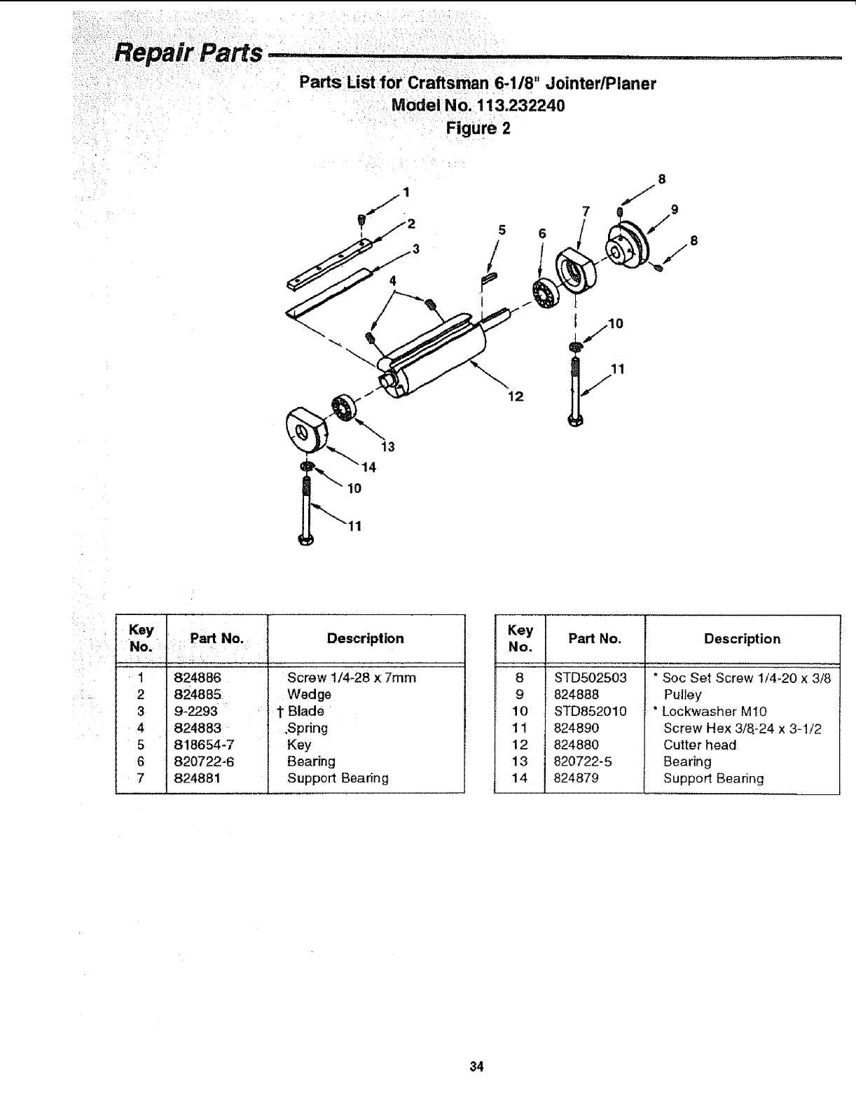
Repair Parts
Parts List for Craftsman 6-1/8" Jointer/Planer
Model No. 113.232240
Figure 2
13
12
8
J
7 9
10
: Key Part.o.
No. Description
I:82488_
2 824885
39*2293 :
4 824883
5 818654-7
6 820722-6
7 824881
Screw 1/4-28 x 7ram
Wed ge
i 1"Blade
.Spring
Key
Bearing
Support Bearing
Key Part No. Description
No.
8
9
10
11
12
13
14
STD502503
824888
STD852010
824890
824880
820722-5
824879
'"* Soc Set Screw 1/4-20 x 3/8
Pulley
* Lockwasher MIO
Screw Hex 3/8-24 x 3-1/2
Cutter head
Bearing
Support Bearing
34
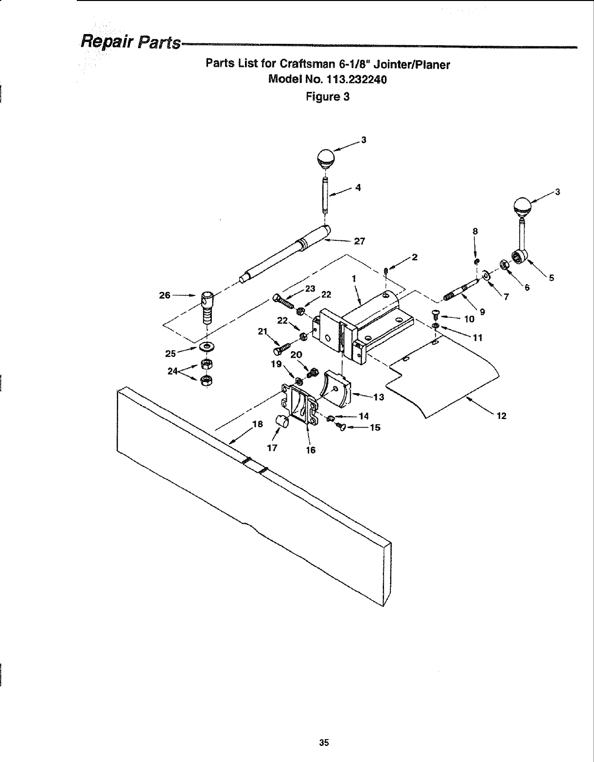
Repair Parts ...... ,rll..i.............. rl,=Ni, ii1,1,111ii iii IN
Parts List for Craftsman 6-1/8" Jointer/Planer
Model No. 113.232240
Figure 3
I
27
17 16
12
35
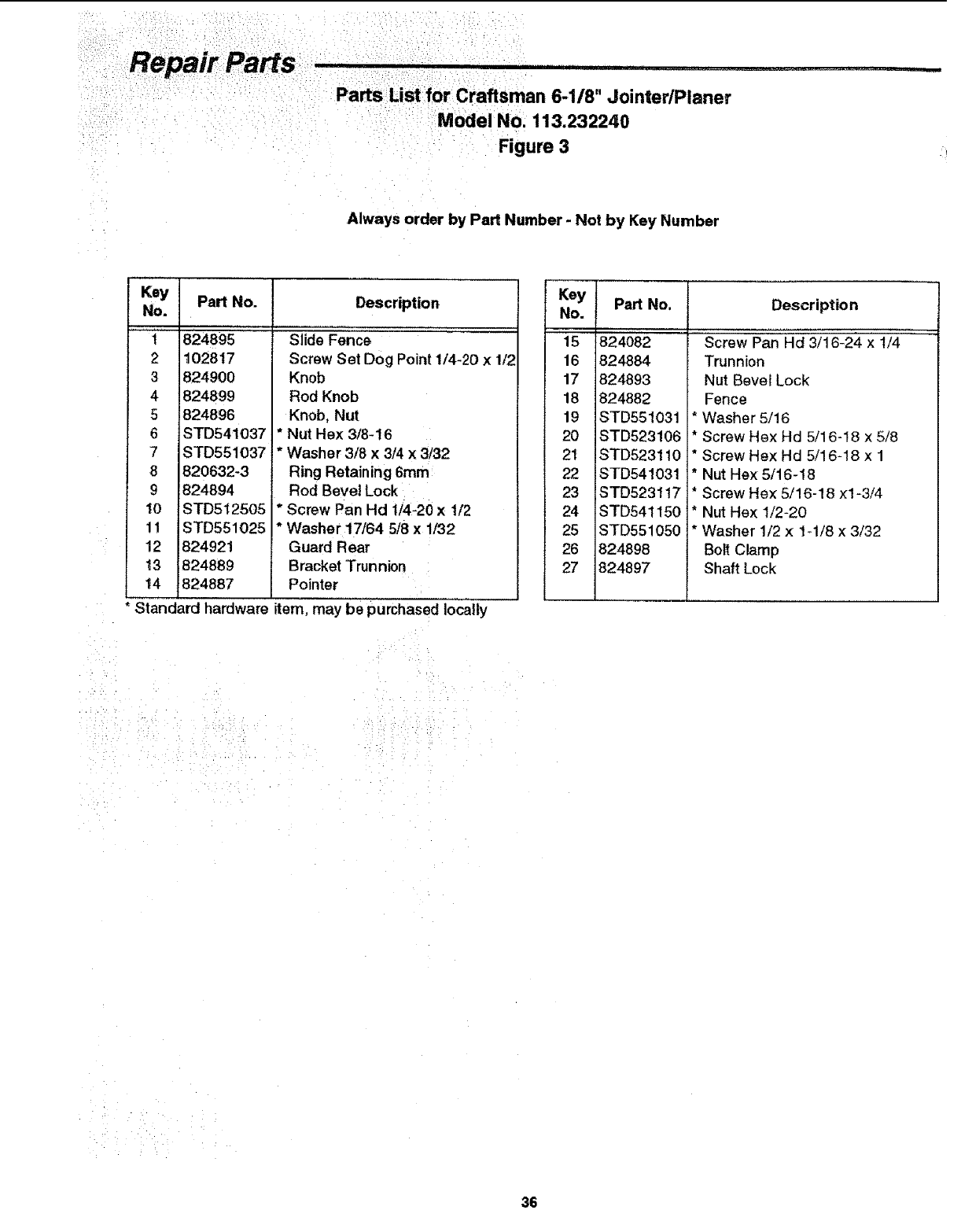
AlwaysorderbyPartNumber-Not by Key Number
Key
No.
t
2
3
4
5
6
7
8
9
10
11
12
13
14
Part No. Description
824895
102817
824900
824899
824896
STD541037 *
STD551037i*
820632-3
824894
STD512505
STD551025
824921
824889
824887
Slide Fence
Screw Set Dog Point 1/4-20 x 1/2
Knob
Rod Knob
Knob, Nut
Nut Hex 3/8-16
Washer 3/8 x 3/4 x 8/32
Ring Retaining 6mm
Rod Bevel Lock
Screw Pan Hd 1/4-20 x 1/2
Washer 17/64 5/8 x 1/32
Guard Rear
Bracket Trunnion
Pointer
Standard hardware item, may be purchased locally
Key Part No.
No.
15 824082
16 824884
17 824893
18 824882
19 STD551031
20 STD523106
2t STD523110
22 STD541031
23 STD5231t7
24 STD541150
25 STD551050
26 824898
27 824897
Description
Screw Pan'Hd 3/16-24-X 1/4 "'
Trunnion
Nut Bevel Lock
Fence
*Washer 5/16
* Screw Hex Hd 5/16-18 x 5/8
* Screw Hex Hd 5/16-18 x 1
* Nut Hex 5/16-18
* Screw Hex 5/16-18 x1-3/4
* Nut Hex 1/2-20
* Washer 1/2 x t-1/8 x 3/32
Bolt Clamp
Shaft Lock
36
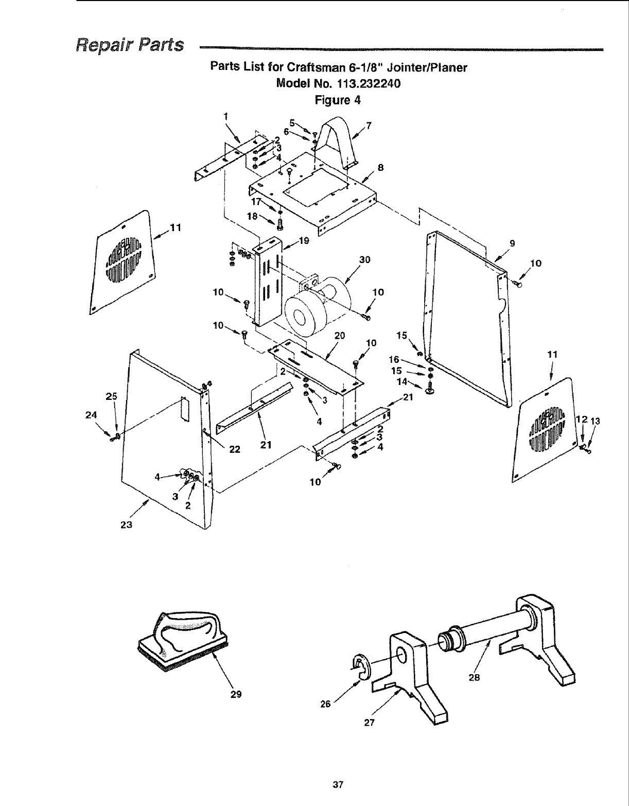
Repair Parts ...........................
!,,i, ! , ii!1,11
Parts List for Craftsman 6-118" JointedPtaner
1
\
Model No. 113.232240
Figure 4
24
25
22 21
2O
3O
10
10
9
t0
11
23
29 26
27
/
28
37

i
Parts List for Craftsman 6-1/8" Jointer/Planer
Model No. 113.232240
Figure 4
Always order by Part Number - Not by Key Number
Key
No. Part No, Description
, ,j
824905
2 STD551031
3 STD852008
4STD541031
5 STD5!2505
6 S:1D551025
7 824920
8824901
9 824842
10 STD533107
11 824906
12 824930
!3 STD600605
14 803835-1
15 STD541037
Bracket Upper '
* Washer 21/64 x 47/64 x 1/16
* Lockwasher 8ram
* Nut Hex 5/16-18
* Screw Pan Hd 1/4-20 x 1/2
* Washer 17/64 x 5/8 x 1/32
Guard Pulley
Panel Top
Panel Rear
* Bolt Carriage 5/!6-18 x 3/4
Panel Side
Ctip
* Screw Pan Hd Ty "T" 6-32 x 1/2
Foot Leveling
Nut Hex 3/8
Standard hardware item, may be purchased localty
Key
No.
16
17
18
19
2O
21
22
23
24
25
26
27
28
29
30
Part No. Description
" '* Washe'r 3/8 x 3/4 x 3/32 ' "
* Lockwasher 10mm
* Screw Hex 3/8-t6 x 3/4
Bracket Motor
Bracket Lower
Stiffener
Grommet
Panel Front
* Screw Pan Hd #8-32 x 3/8
* Lockwasher #8
Ring Retaining
Gauge Knife
Rod Knife Gauge
Push Block
Motor Asm
STD551037
STD852010
STD523707
824904
824903
824902
824909
824841
STD510803
STD551208
820632-2
824925
824926
67062
See Fig. 5
38

Repair Parts ......
Parts List for Craftsman 6-118" JointedPlaner
Model No. 113.232240
Figure 5
16
17
18
Always order by Part Number - Not by Key Number
Key
No,
i
2
3
4
5
6
7
8
9
10
IPart No.
9-22255
824719
817357-6
STD551008
824912
824913
824914
169123-15
82491 t
STD551208
Description
,;,,, , ....
Key Switch
Switch Locking
Screw Ty AB M4 x 1.6-18
* Washer #8
Plate Switch Bezel
Plate Switch Box
Box Switch
Strain Relief 6P3-4
Cord w/Plug
* Lockwasher #8
Standard hardware item, may be purchased locally
Key
NO.
'il
12
13
14
!5
16
!7
18
19
Part No. Description
STD541008
STD5t0803
817393-6
818654-8
824931
STD502503
824910
69164
824915
* Nut #8-32
* Screw Pan Hd #8-32 x 3/8
V-Belt A-32
Key
Pulley
* Screw Set 1/4-20 x 3/8
Motor
Strain Relief 6N3-4
Cord Motor
39

iiii i,=,, iii i! i_,,11! ,, i
f
Model No.
113.232240
Jointer/Planer
with Legs and Motor
The model number of your 6-1/8
Inch JointedPlaner will be found
on a plate attached to the base.
When requesting service or
ordering parts, always provide
the following information:
• Product Type
-Model Number
-Part Number
•Part Description
CONTRACTOR SE
6-1/8 INCH
JOmNTER/PLANER
Forthe repair or replacement partsyou need
Call 7am - 7 pro, 7 days a week
t-800-366=PART
(1-B00-366-7278)
For in-homemajor brand repairservice
Call 24 hours a day, 7days aweek
1-800-4-REPAIR
(1-800-473-7247)
Forthe location of a
SearsRepairService Center in your area
Ca!124 hoursa day, 7 days a week
1-800-488-1222
Forinformatio, onpurchasinga Sears
Maintenance Agreementorto inquire
about an existingAgreement
Cal! 9 am- 5pro,Monday-Saturday
1-800-827-6655
SEARS
America _ Repasf ,_pec_a#sts
Part No. SP597t
J _ ........................................ ---------,m == i1= ==_
Sears, Roebuck and C(_., Hoffman Estates, IL. 60179 U.S.A.
Form No, SP5971-2 Printed in Taiwan 5/97
