Craftsman 113236180 User Manual SCROLL SAW Manuals And Guides L0803545
CRAFTSMAN Saw Scroll Manual L0803545 CRAFTSMAN Saw Scroll Owner's Manual, CRAFTSMAN Saw Scroll installation guides
User Manual: Craftsman 113236180 113236180 CRAFTSMAN SCROLL SAW - Manuals and Guides View the owners manual for your CRAFTSMAN SCROLL SAW #113236180. Home:Tool Parts:Craftsman Parts:Craftsman SCROLL SAW Manual
Open the PDF directly: View PDF ![]() .
.
Page Count: 19

Future Reference
MODEL NO.
1!3.23($180
SCROLL SAW
Variable Speed
Serial
Number
Model and ser;al number may be found
attached to the underside of the work-
table.
You should record both model and
serial numberin a safeplace for future
use.
FOR YOUR
SAFETY:
READ ALL
INSTRUCTIONS
carefully.
16" VARIABLE
ELECTRONIC
SCROLL SA
•assembly
•operating
orepair parts
, .... _ _ ___=__ ....
Sotd by SEARS, ROEBUCK AND CO., Chicago, ILo 60584 U.S.A.
Par11'qo.SP5367

SAW
materialor workmanship,Searswillrepair
WARRANTY'SERVICE IS AVAILABLE BY SIMPLY CONTACTING THE NEAREST SEARS SERVICE CENTER!DEPARTMENT
THROUGHOUT THE UN TED STATES
Thiswarranty applies only while this product is used in the United States,
This warranty gives you specific legal rights and you may also have other rights which vary from state to state.
SEARS, ROEBUCK AND CO., DEPT. 698/731A Sears Tower, Chicago, IL 60684
ill i , ii • •
eneral safety instructions for power tools
1= KNOW YOUR POWER TOOL 10.
Read and understand the owner's manual and
labels affixed tothe tool. Learn itsapplication and
limitations as well as the specific potential haz-
ards peculiar to this tool. 11.
2. GROUND ALL TOOLS
ThiS tOolis equipped with an approved 3-conduc-
tor cord and a 3-prong grounding type plug to fit
thepropergroundingtype receptacle. The green
conductor in the COrd is the grounding wire.
Never connect the green wire to a live terminal.
3. KEEP GUARDS IN PLACE
- in working order, and in adjustment and align-
ment.
4. REMOVEADJUSTING KEYS AN DWRENCHES
Form ahabit of checking to see tha_ keys and
adjustingwrenches are removed from toolbefore
turning it on.
5. KEEP WORK AREA CLEAN
Cluttered areas and benches invite accidents.
Floor must not be slippery due tOwax or sawdust.
6. AVOID DANGEROUS ENVIRONMENT
Don't use power tools indamp Orwet locations or
expose thereto rain. Keepworkareawell lighted.
Provide adequate surrounding wo*rkspace.
7. KEEP CHILDREN AWAY
All visitors should be kept a safe distance from
work area.
8. MAKE WORKSHOP CHILD PROOF
- with padlocks, master switches, or by removing
starter keys.
9.
12.
USE RIGHT TOOL
Don't force tool or attachment to do a job it was
not designed for.
WEAR PROPER APPAREL
DO not wear loose clothing, gloves, neckties or
jewelry (rings, wristwatches) to get caught in
moving parts. NONSLIP footwear is recom-
mended. Wear protective hair covering to con-
tain tong hair. Roll long sleeves above the elbow.
USE SAFETY GOGGLES (Head Protection)
Wear safety goggles (must comply with ANSI
Z87.1) at all times. Everyday eyeglasses only
have impact resistant lenses, they are NOT safety
glasses'. Also, use face or dust mask if cutting
operation is dusty, and ear protectors (plugs or
muffS) during extended periods or operation,
13.
14.
15.
16.
17.
SECURE WORK
Use clamps or avise to hold work when practical.
It's safer than using your hands and frees both
hands to operate tool.
DON'T OVERREACH
Keep proper tooting and balance at alt times.
MAINTAIN TOOLS WITH CARE
Keep tools sharp and clean for best and safest
performance. Follow instructions for lubricating
and changing blades, bits, cutters, etc.
DISCONNECT TOOLS
-before servicing; when changing accessories
such as blades, bits, cutter, etc.
AVOID ACCIDENTAL STARTING
Make sure switch is in"OFF" position before 3lug-
ging in power cord.
i,
2

h,i ,i,i i i i1,1 i
18. USE RECOMMENDED ACCESSORIES
Consult the owner's manual for recommended
accessories. Follow the instructionsthat accom-
pany the accessories. The use of improper
accessories may cause hazards.
19. NEVER STAND ON TOOL
Serious injury could occur if the tool is tipped or if
the cutting tool is accidentally contacted.
Do not store materials above or near the tool such
that it is necessary to stand on the tool to reach
them.
20. CHECK DAMAGED PARTS
Befo re further use oft hetool, a guard orother part
that is damaged should be carefully checked to
21.
22.
i -iii i
ensure that itwill operate properly and perform its
intended function. Check for alignment of mov-
ing parts, binding of moving parts, breakage of
parts, mounting, and any other conditions that
may affect its operation. A guard or other part
that is damaged should be properly repaired or
replaced.
DIRECTION OF FEED
Feed work into a blade or cutter against the
direction of rotation of the blade or cutter only.
NEVER LEAVE TOOL RUNNING UNAT-
TENDED
Turn power off. Don't leave tool until it comes to
a complete stop.
additional safety instructions for scroll saw
Safety is a combination of operator common sense and B. Do not cut pieces of material too small to hold by
alertness at all times when the scroll saw is being used.
WARNING: FOR YOUR OWN SAFETY, DO NOT
ATTEMPT TO OPERATE YOUR SCROLL SAW UN-
TIL IT IS COMPLETELY ASSEMBLED AND IN-
STALLED ACCORDING TO THE INSTRUCTIONS,..
AND UNTIL YOU READ AND UNDERSTAND THE
FOLLOWING. Page
1. General Safety Instructions for Power Tools .... 2
2. Assembly .............................................................. 7
3. Basic Scroll Saw Operation .............................. 14
4. Maintenance ....................................................... 16
5. Stability of Machine.
Your scroll saw must be bolted securely to stand or
work bench, In addition, if there is any tendency for
the scroll saw to move during certain operations, bolt
your scroll saw stand or workbench to the floor.
6, Location
To avoid fire or explosions, never use this tool where
flammable vapors or gases are in the air. To avoid
injury from dropped unit, unplugsaw before moving it.
This scroll saw is intended for indoor use only.
7. Protection: Eyes, Hands, Face, Ears, Body
A. To avoid being pulled into the blade:
1. Roll long sleeves above elbows
2. Do not wear:
a. Gloves
b. Jewelry
c. Ties or other loose clothing
3. Tie back long hair
ii,Ju=u __ _____
hand outside the blade guard/hold down.
C, Avoid awkward hand positions where a sudden
slip could cause a hand to roove into the blade.
D. To avoid slips due to lifting of the work piece make
sure the blade teeth point downward toward the
table.
E. To avoid blade breakage always adjust blade
tension correctly.
F. To avoid losing control of the work piece or tool:
1. When cutting a large piece of material make
sure it is fully supported at table height.
2. Hold the work piece firmly against the table.
3. Do not feed the material too fast while cutting.
Only feed the material fast enough so that the
blade will cut.
4. Use caution when cutting off material which is
irregular in cross section and could pinch the
blade before the cut is completed. A piece of
molding, for example, must Iay flat on the table
and not be permitted to rock while being cut.
5. Use caution when cutting off round material
such as dowel rods, or tubing. They have a
tendency to roll while being cut causing the
btadeto bite. Use a V-blockto controlthe piece.
G. When backing the blade out of the workpiece, the
blade may bind in the kerr (cut).,. this is usually
caused by sawdust clogging up the keri, If this
happens: Turn off the scroll saw,., remove plug
from power source outlet,., wedge open the kerr
•.. back the blade out of the workpiece.
H. To avoid unsupervised work, use or accidents due
to inattention:
1, Never leave the scroll saw work area with the
power on, before the machine has come to a
complete stop.
2. Do not perform layout, assemb!y or set up work
on the tame while the cutting tool is in operation

or su
8, Should any part of this scrollsaw bt
fail in any way, or any
perform properly, shut off and remove
plug from power supply outlet. Replace damaged,
missing, and/or failed parts before resuming opera-
tion.
9. Think Safety.
Safety is a combination of operator common sense
and alertness wheneverthe scroll saw is in operation.
The operation of any power tool ca_ result in foreign
objects being thrown into the eyes, which can result in
severe eye damage. Always wear safety goggles
complying with ANSI Z87.1 (shown on Package) before
commencing power tool operation. Safety goggles are
available at Sears retail or catalog stores.
WARNING: ALWAYS KEEP ALERT. DO NOT AL-
LOW FAMILIARITY (GAINED FROM FREQUENT USE
OF YOUR SCROLL SAW) TO CAUSE A CARELESS
MISTAKE. ALWAYS REMEMBER THAT A CARE-
LESS FRACTION OF A SECOND IS SUFFICIENTTO
INFLICT SEVERE INJURY,
f
/FOR YOUR OWN SAFETY: \
Read and understand owner's
manuat before operating SCroll Saw.
BALWAYS wear SAFETY GOGGLES
complyingwith ANSI Z87,1.
o PROPERLY ADJUST HOLDDOWN,
=Hold workpiece down firmly,
o Turn sawoff and LOCK SWITCH
before adjusting saw, changing
bladeor leaving area.
•When INSTALLING BLADE: Blade
teeth must point down, Tension
blade by turning knob clockwise
one full turn beyond take-up of
alack. Fol!ow ©omplnte installation
and checking procedure in owner's
60 Hz AC oaty, 1.2 empm EI_'_
electrical connections 3-PRONG PLUG
WARNING: TO AVOID ELECTRICAL HAZARDS, FIRE
HAZARDS, OR DAMAGE TO THE TOOL, USE
PROPER CIRCUIT PROTECTION. YOUR SAW IS
WIRED AT THE FACTORY FOR 120V OPERATION.
CON NECT TO A 120-V, 15-AMP, BRANCH CIRCUIT
AND USE A 15-AMP FUSE OR CIRCUIT BREAKER.
TO AVOID SHOCK OR FIRE, IF POWER CORD IS
WORN OR CUT, OR DAMAGED IN ANY WAY, HAVE
IT REPLACED IMMEDIATELY.
\
GROUNDING PRONG
PROPERLY GROUNDED
3-PRONG OUTLET
IFNOT PROPERLY GROUNDED THIS POWER TOOL
CAN CAUSE ELECTRICAL SHOCK- PARTICULARLY
WHEN USED IN DAMP LOCATIONS CLOSE TO
PLUMBING, IF AN ELECTRICAL SHOCK OCCURS
THERE IS ALSO THE POTENTIAL OF A SECON-
DARY HAZARD SUCH AS YOUR HANDS CONTACT-
ING THE SAWBLADE. NOT ALL OUTLETS ARE
PROPERLY GROUNDED. IF YOU ARE NOT SURE
THAT YOUR OUTLET IS PROPERLY GROUNDED,
HAVE ITCHECKED BY A QUALIFIED ELECTRICIAN.
'(our unit has aptug that looks like the one shown.
The ground conductor has a green jacket and is at-
tached to the tool housing at one end and to the ground
prong in the attachment plug at the other end.
This plug requires a mating 3-conductor grounded type
outlet as shown above.
WARNING: TO MAINTAIN PROPERTOOLGROU hiD-
INGWHENEVERTHE OUTLETYOU ARE PLANNING
TO USE FOR THIS POWER TOOL IS OF THE TWO
PRONG TYPE, DO NOT REMOVE OR ALTER THE
GROUNDING PRONG IN ANY MANNER. USE AN
ADAPTER AS SHOWN AND ALWAYS CONNECT
THE GROUNDING PRONG TO KNOWN GROUND.
, ii 4

_._.___.._._l_ __ iml! nl lU nl ii __ i iii nll IIH'I_-- _.' _.-_-J _HJlJ i,,,,,,,r
It is recommended that you have aqualified electrician a. MOTOR IS OVERLOADED -Overloading can
replace the two prong outlet with aproperly grounded
three prong outlet.
An adapter as shown is available forconnecting the plug
to 2-prong receptacles. The green grounding lead
extending from the adapter must be connected to a
permanent ground such as a properly grounded outlet
box.
GROUNDING LUG
scREw/I I
\ I { ,iF AKE o.ETN,S,s
._ _,.,.,.. .... _; i f_ CONNECTED TO A
_-_n_,_ fLU',= ,_" [,_;-,_,1 KNOWN GROUND
\ t_"* -I!H]}
!RECEP AC.E
ADAPTER
WARNING: THE ADAPTER ILLUSTRATED IS FOR
USF ONLY IF YOU ALREADY HAVE A PROPERLY
GROUNDED 2-PRONG RECEPTACLE,
occur if you feed too rapidly.
b_ LOW VOLTAGE - Although the motor is designed
for operation on the voltage and frequency speci-
fied on the motor nameplate, normal loads will be
handled safely on voltages not. more than I0%
above or below the nameplate voltage. Heavy
loads, however, require that voltage at motor ter-
minals equals the voltage specified on nameplate.
5. Most motor troubles may be traced to loose or
incorrect connections, overload, reduced input volt-
age (such as small size wire inthe supply circuit) or to
ovedy long supply circuit wire. Always check the
connections, t he load and the supply circuit whenever
motor fails to perform satisfactorily. Check wire size
and length with the "Wire Size Chart" betow.
MOTOR SAFETY PROTECTION
1. This tool should be connected to a 120V, t5 amp
branch circuit with a 15 amp fuse or circuitbreaker.
Failure to use the proper size fuse can result in
damage to the motor.
2. If the motor fails to start, control knob should be
pushed down to "OFF" position immediately. UN-
PLUG THE TOOL. Check the saw blade to make sure
it operates freely. If the blade is free, try to start the
motor again. If the motor still does not start, refer to
the "Motor Troubleshooting Chart."
WiRE SIZES
The use of any extension cord will cause some toss of
power. To keep this to a minimum and to prevent
overheating and motor burn-out, use the table below to
determine the minimum wire size (A.W.G.) extension
cord. Use only 3-wire extension cords which have 3-
prong grounding type plugs and 3-poIe receptacles
which accepts the tools plug.
CAUTION: For circuits that are farther away from
electrical service box, the wire size must be in-
creased proportionately in order to deliver ample
voltage to the saw motor.
3. If the motor suddenly stallswhile cutting wood, turn
the power switch off, unplug the tool, and free the
blade from the wood. The motor may now be re-
st&rted and the cut finished.
4. Frequent "blowing" of fuses or tripping of circuit
breakers may result if:
i i
Lengthof the 120 Volts Wire Sizes Required
Conductor (American Wire Gage Numbe0
0- 25 Ft. 16
26 -50 Ft. 14
51 - 100 Ft. 12
i, UUllUl, ii I,,,,,H i i,i ,nn
glossary of terms for woodworking
1. Kerr- the slot cut by the blade
2, Leading Edge - the edge of the workpiece which is
pushed into the blade first.
3. Sawblade Path -The area of the workpiece directly
in line with and moving toward the sawblade edge.
4. Blade Tooth Set - the distance that the edge of the
sawbtade tooth is bent (on set) outward from the side
of the blade.
5. Trailing Edge -the workpiece edge last cut by the
sawblade.
6. Workplece -the item on which the culting operation
is being performed.
contents -.,
Warranty information ..... ;:.......:.._....... :........ .i," ,"_12
General Safety Instructions for Power Tools ........2
Additlonal Safety Instruction for Scrol| Saws ....... 3
Electrical Information ...,..,..,.., ........... ;.i...... .......... 4
Glossary of Terms for Woodworking .... . ..... .........5
Unpacking & Checking Contents ;........... .i............. 6
Assembly . o ., . :
Setting the Table for Horizontal or
Bevel Cutting _..................... _,..,...................... 7
Aligning the Bevel Indicator ........................ 8
Mountlr_g the Scroll Saw .................................... ....9
Removing and Installing Blades ........................... 10
Recommended Accessories ................................. 16
Troubleshooting ..................................................... 17
Wiring Diagram ....................................................... 17
Repair Parts ............................................................ 18
Service lnformaUon ................................................ 20
"4
unpack n
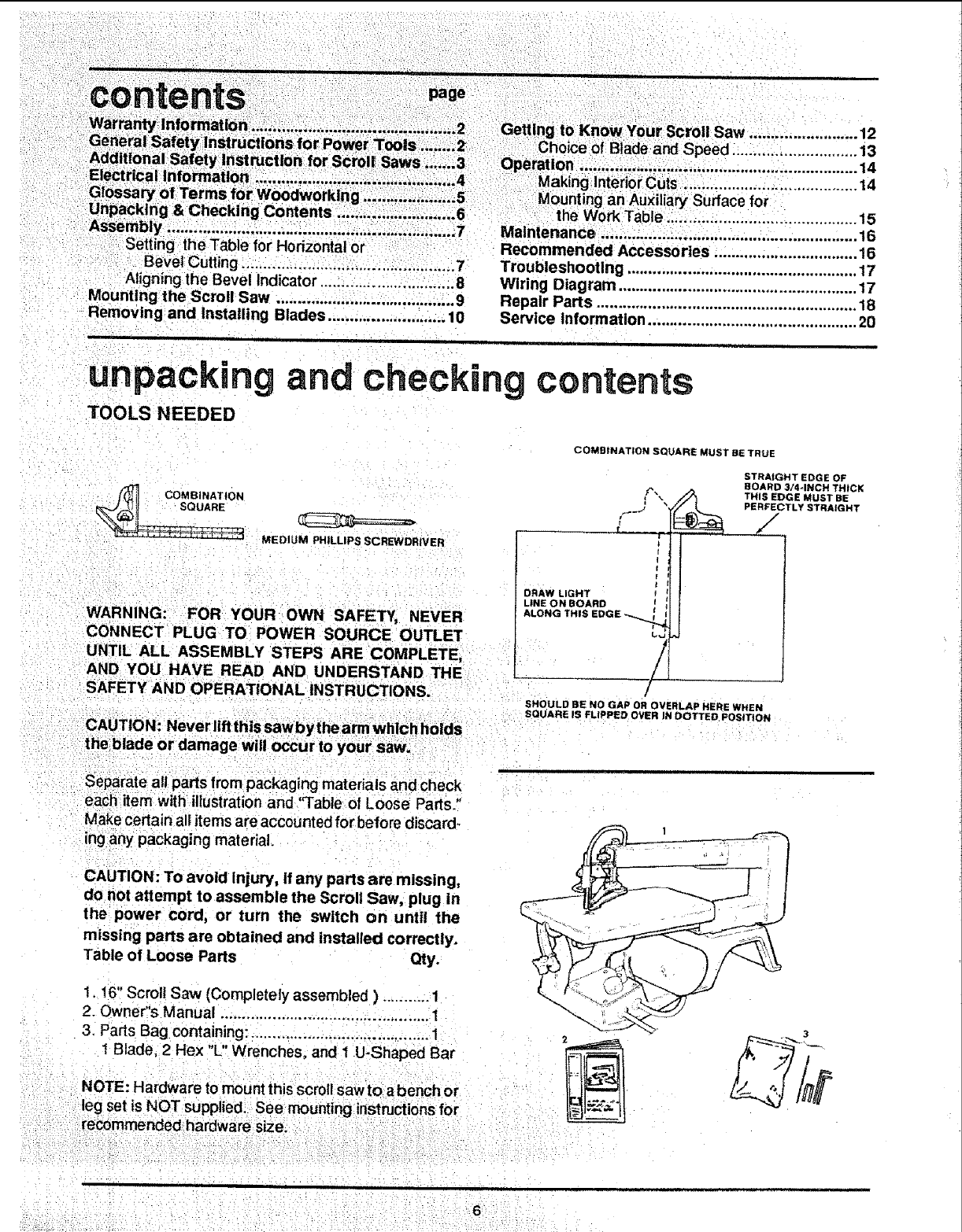
TOOLS NEEDED
and checking contents
(_ COMBINATION
MEDIUM PHILLIPS SCREWDRIVER
COMBINATION SQUARE MUST BE TRUE
STRAIGHT EDGE OF
BOARD 3/4*INCH THICK
THIS EDGE MUST BE
PERFECTLY STRAIGHT
/
/
WARNING: FOR YOUR OWN SAFETY, NEVER
DRAW LIGHT
LINE ON BOARD
ALONG THIS
!
AND YOU HAVE READ AND UNDERSTAND THE L__
SAFETY AND OPERATIONAL INSTRUCTIONS.
SHOULD BE NO GAP OR OVERLAp HERE WHEN
SQUARE IS FLIPPED OVER IN DOTTED POSITION
Separate all parts from packaging mater als and check
each item with illustration and "Table of Loose Parts."
Make certain all items are accounted for before discard_
ing any packaging material.
CAUTION: To avoid Injury, if any parts are missing,
donot attempt to assemble the Scroll Saw, plug in
the power cord, or turn the switch on until the
missing parts are obtained and installed correctly.
Table of Loose Parts Qty.
1,16" Scroll Saw (Completely assembled ) ........... 1
2. Owner"s Manual ................................................ 1
3. Parts Bag containing: ......................................... 1
t Blade, 2 Hex "L" Wrenches, and 1 U-Shaped Bar
NOTE: Hardware to mount this scroll sawto abench or
leg set is NOT supplied. See mounting instnJctions for
3

DO NOT LIFT SAW FRAME
BY THIS ARM {LIFT HERE)
BLADE HOLBER
BLADE
BEVEL
BEVEL LOCK
(LIFT HERE)
WARNING: FOR YOUR OWN SAFETY, NEVER
CONNECT PLUG TO POWER SOURCE OUTLET
UNTIL ALL ASSEMBLY STEPS ARE COMPLETE,
AND YOU HAVE READ AND UNDERSTAND THE
SAFETY AND OPERATIONAL iNSTRUCTIONS.
,,,,11111iii ii ii ii i !l
1. Liftthe saw by the frame and base and place scroll
saw on work bench.
2. Familiarize yourself with the controls and features of
this scroll saw indicted in illustration.
SETTING THE TABLE FOB HORIZONTAL
OR BEVEL CUTTING
1. The scroll saw work table can be tilted to the left for
bevel cutting up to 45 degrees from the 0 degree or
herizentaI cutting position.
2. A bevel scale is provided under the work table as a
convenient reference for setting the approximate
table angte for bevel cutting.
When greater precision is required, make trial cuts
and adjust the table as necessary for your require-
ments.
SCALE

NDICATOR
blade.
and rnove the table
r or at aright
BEVEL LOCK
KNOB
3; Remove blade support and hold down by loosening
the screw in the front of the blade support with a hex
"L"wrench.
LOOSEN SCREW
iJ
BLADE SUPPORT
AND HOLD DOWN
i
CHECK FOR
SPACE BETWEEN
SQUARE AND
BEVEL LOC_
KNOB_
5. When the space between the square and the blade is
uniform, tighten the bevel lock knob.
The table shoutdnowbe approximatel y 90 degrees to
the blade.
BLADE FLUSH
AGAINST SQUARE

6. Loosen the screw holding the bevel scale pointer and
adjust pointer to 0 degrees. Tighten screw.
Remember, the bevel scale is a convenient guide, but
should not be relied upon for precision.
Reassemble the blade support and hold down.
Make trial cuts in scrap wood to determine if your
angle settings are correct. Adjust the table as re-
quired.
BEVEL SCALE POINTER SCREW
mounting the scroll saw to a bench
Your scroll saw must be bolted securely to stand or work
bench. In addition, ifthere is any tendency for the scroll
saw to move during certain operation, bolt your scroll
saw stand or workbench to the floor. SCROLL SAW BASE
1. Hardware to mount this saw to a workbench is NOT
supplied with the saw, However, we recommend the
hardware used be no smaller than the following.
Quantity Description
4
4
8
Hex Head Screws, 1/4-20 x Length
as required
Flat Washers, 9/32" I,D,
Lockwashers, 9/32" 1.D.
Hex Nuts, 1/4-20
2. A soft foam pad to place between your scroll saw and
workbench is NOT supplied with the saw. However,
we highly recommend the use of such apad to reduce
noise and vibration.
Quantity Description
1/2" FOAM PAD
(OPTIONAL)
|-I
i!
l_ WORKBENCH
t
|
_jHAkE FLATWASHER
OCKWASHER
X NUT
M NUT
HEX HEAD SCREW
Soft foam pad such as carpet padding,
24" x 12" x 1/2"
Do NOT overtighten mounting bolts - leave some cush-
ion in the foam pad for absorbing noise and vibration.

i
removing and nst
1. Unplug power cord from outlet.
2. Loosen tension on blade by turning tension knob
counterclockwise about four full turns. Loosen the
hex screw of blade holder and push it toward left di-
rection.
3. Support the blade holder by using the "U" shaped bar
provided in the darts bag,
4. Slip one side of bar behind the holder while the other
side is placed through the hole provided in front of the
blade holder.
ing binaries TENSION KNOB
_J
f
"'U'SHAPED BAR
\
J
7
J
SCREW
5. Loosen the lower blade holder screw in the same way
you Ioosened the upper blade holder in Steps 2 & 3.
Remove blaae by pulling forward on blade and then
lifting the blade through the access hole in the table.
LOOSEN LOWER
BLADE HOLDER
SCREW
6. Prior to installing blade, make sure the teeth of the
blade point down.
UPPER
BLADE HOLDER
Look at the lower blade holder closely, installthe new
blade through the access hole of the table into the
lower blade holder. With hex "L" wrench, lasten the
lower blade holder, but not completely tight. The_
install the U-shaped bar into the upper blade holder,
push the blade into the upper blade holder, and
tightenthe screw of the upper blade holder. Using the
.... sametechnique tighten the screw of the lower blade _'_
: holder again_ : Fina!ly ipiace tension on blade by
:i iurning tension knob €l_kwise after U_shaped bar
_ ___ HOLDER

ii i, i1,,, i
,Adjust the blade support by loosening the screw on
the top of blade support with a hex "L wrench, and
tighten the screw after adjusting.
Adjust the blade holder to the table by loosening the
lockknob. Make sure the foot is positioned properly
against the table, The hex screw (rear of hotd down
foot) may be loosened to adjust hold down fool.
Retighten hex screw after adjustment is complete.
Adjust the blade holder to the height of workpiece by
adjusting the hold-down foot directly on top of work-
piece and tighten lock knob,
BLADE HOLID*OOWN FOOT
ADJf3ST[_G KNOB
f
_HOLD-DOWN FOOT
TO REST LIGHTLY
ON TOP OF
WORKPIECE
8. Before plugging saw in, use your fingers to raise and
Iowerthe lower arm so the eccentric mechanism turns
at least one cycle to insure the blade is properly in-
stalled.
NOTE: Do not remove guard
\
HOLD_DOWN
ADJUSTING
SCREW
ECCENTRIC
MECHANISM
\
BEVE
3
BLADE HC
BEVEL
BLADE HOLDER
iBLADE
2HOLD
BEVEL LOCK KNOB
6
SPEED CONTROL KNOB
ON/OFF KNOB
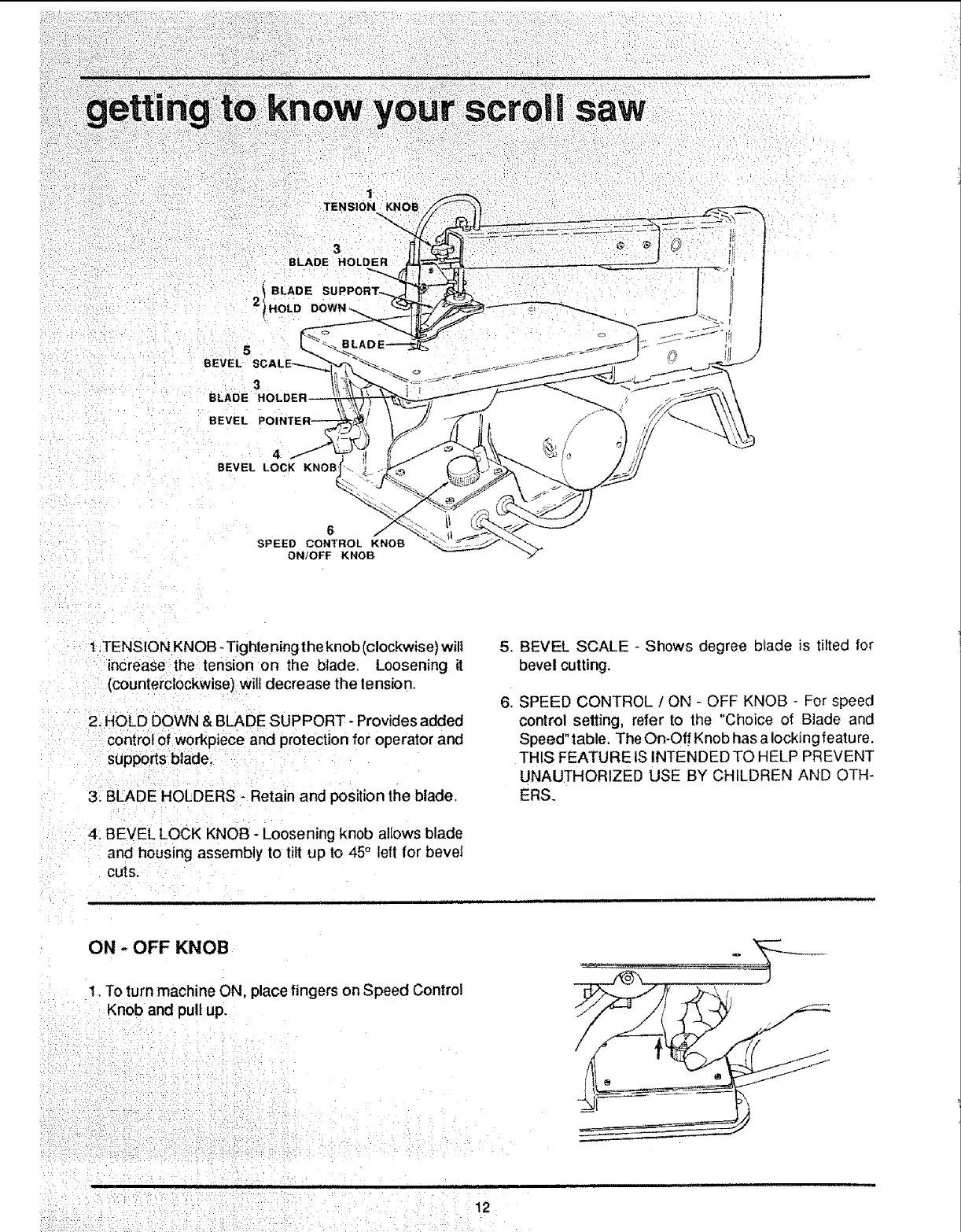
1,TENSION KNOB -Tighteningthe knob (clockwise) will
_ncreasethe tension on the blade. Loosening it
(counterclockwise) wilt decrease the tension,
2. HOLD DOWN & BLADE SUPPORT- Provides added
control of workpiece and protection for operator and
supports blade,
3, BLADE HOLDERS - Retain and position the blade,
4. BEVEL LOCK KNOB - Loosening knob allows blade
and housing assembly to tilt up to 45° left for bevel
CUTS.
5. BEVEL SCALE - Shows degree btade is tilted for
bevel cutting.
6 SPEED CONTROL /ON - OFF KNOB - For speed
control setting, refer to the "Choice of Blade and
Speed" table, The On-Off Knob has a locking featu re.
THIS FEATURE IS INTENDED TO HELP PREVENT
UNAUTHORIZED USE BY CHILDREN AND OTH-
ERS.
ON -OFF KNOB
1. To turn machine ON, place fingers on Speed Control
Knob and pull up.
12

]
2. To turn machine OFF, control knob is pushed down.
NEVER LEAVE THE MACHINE UNATTENDED
UNTIL IT HAS COME TO A COMPLETE STOP.
The variable speed control may be adjusted to the
approximate speeds identified on the control panel.
Suggested speeds are identified below. Turn the
control knob clockwise ( _ ) to increase strokes
per minute and counterclockwise ( (-_ ) to reduce
the strokes per minute,
3. To lockknob in OFF position, install a padlock through
the post above the knob as illustrated, and lock the
padlock, (Padlock is not supplied with the saw.)
WARNING: FOR YOUR OWN SAFETY, ALWAYS
PUSH THE KNOB "OFF" WHEN MACHINE tS NOT
IN USE... ALSO... IN THE EVENT OF A POWER
FAILURE (ALL OF YOUR LIGHTS GO OUT) PUSH
KNOB OFF,,. "LOCKOUT" YOUR KNOB WITH A
PADLOCK AS SHOWN. THIS WILL PREVENT
THE MACHINE FROM STARTING UP AGAIN WHEN
THE POWER COMES BACK ON.
ii ,l llll
CHOICE OF BLADE AND SPEED
LOCKING POST
The scroll saw accepts a wide variety of blade widths
and thicknesses+ The blade width and thickness and the
number of teeth per inch are determined by the type of
material and the size of the radius being cut, See the
following chart.
Teeth/Inch
10
15
18
Width
.110"
,110"
095"
Speed
Thickness (Strokes!Mtn.) Material Cut
.02O" C{1200- 1500)
.020" B (600 -1200)
_010" A (500 - 600)
Poputar sizes for cutting hard a oft woods 3/16" upto 2".
Also ptastics, paper, felt, bone, etc.
Wood, plastic, extremely thin cuts on materials 3/32" to
1/2" thick.
For tight radius work in thin m Lterials 3132" to "_18"wood
veneer, wood, bone, f;ber ivory, plaslic, etc.
As ageneral rule, always select the narrowest bIades recom-
mended for intricate curve cutting and widest blades for
straight and large curve cutting operation.
_3

your scroll
to iollow the wood grain as you
• !. The saw does not cut wood by itself. You alJowthe g. intended to cut wood or or material
saw to cut wood by guiding the wood into the blade as similar to wood only:
it moves,
10, When choosing a blade to use with your scroll saw,
2 The blade teeth cut wood ONLY on the down stroke, consider the following carefully.
3. 'You must guide the wood into the blade slowly be-
cause the teeth of the blade are very small and they
can only remove wood when they are on the down
stroke.
Very fine, narrow blades should be used to scroll
cut in thin wood 1/4" thick or less.
To cut wood over 1/4" thick, use wider blades.
4. There is a learning curve lor each person who wants
to use this saw. During that period of time, it is
expected that some blades wilt break until you learn
how to use the saw and receive the greatest benefit
from the blades.
5 Best resufts are achieved when cutting wood less
than one inch thick.
6 When cutting wood thicker than one inch, the user
must guide the wood very, very slowly into the blade
Most blade packages state the size or thickness
of wood which that bmadeis intended to cut, and
the radius size of curve, which can be cut with
that blade.
Wider blades can't cut curves as tight or small as
thinner blades.
Narrower blades work well only on thinner wood
material.
and take extra care not to be nd or twist the blade while
cutting in order to maximize blade life.
i1. This saw uses 5" long plain end type blades only.
See your Sears Catalog or Retail Store for acces-
sop,,'blades.
7, Teeth on scroll saw blades wear out and as such must
be replaced frequently for best cutting results. Scroll 12.
saw blades generally stay sharp for I/2 hour to 2
hours of cutting.
8i Toget ac_rate cuts, be prepared to compensate for
u J _= , :l ,r, ===l lu L J,,lu,, ,U J i: ....... Ju,= . ._JCJ['JJJ==',=
MAKING INTERIOR SCROLL CUTS
Blades wear faster when cutting plywood, which is
very abrasive; when sawing wood which is thicker
than3!4" blade stroke; and when sawing hardwood,
or when side pressure is placed on the blade.
!. One of the features of this saw is that it can be used
to make sero(I cuts on the interior of a board without
breaking or cutting into theoutline or perimeter of the
board.
1/4" HOLE IN
WORKPIECE
CENTERED OVER
HOLE IN TABLE
WARNING: TO AVOID INJURY FROM ACCIDEN-
TAL STARTING, ALWAYS PUSH CONTROL KNOB
"OFF" AND REMOVE PLUG FROM POWER
SOURCE OUTLET BEFORE REMOVING OR RE-
PLACEtNG THE BLADE.
: 2, To make intedor cuts inaboard, remove the scroll saw
blade as explained in the Assembly Section.
a ii4t, h01e in the board you will use to make
..... iin the
,i i ," = =,uu ,,,l=,,, , ,,Hu
5. Install blade through hole in board and adjust btade
tension.
6. When finished making the interior scroll cuts, simply
remove the blade from the blade holders, as de-
scribed in the Assembly Section, and remove the
board form the table.

_-- _ J l[ _ I Jlill @ _::__ .................. i
MOUNTING AN AUXILIARy WORK TABLE
1. Four holes are provided in the work table so you can
easily attach an auxiliary work surface to the saw if
your needs require.
2. Mounting an auxiliary table can allow you to build a
larger support area to suit your project, and could
render asmoother work surface, as your needs
require and an auxiliary surface can give you more
support close tO the blade for special cutting needs
like very small or detailed projects.
WARNING: TO AVOID TOOL TIPPING OR SUP-
PORT FAILURE, AUXILIARY WORK SURFACE
SH OULD NOT EXCEED 24" X 12" X 1/4" AND SAW
MUST BE FASTENED TO A WORKBENCH,
At least a 1/4" hole will be needed inthe auxiliary surface
to insert blades,
DRILL the hole for the blade first. Then MARK location
of other holes.
HARDWARE (not supplied) - recommended to mount
auxiliary surface to saw worktable.
Quantity Description
4
4
4
4
Flat Head Screws #8-32 x 1
Flat Washers #8
Lockwashers #8
Hex Nuts #8-32
4FLAT HEAD
SCREWS
1 COUNTERSINK THE AREA AROUND
.EAGH HOLE SO SCREW HEAD WILL
/NO'!r G_T IN YOUR WAY AND AUXILIARY
iSLI_FACE WILL BE SMOOTH,
t_oPTtONAL AUXILIARY WORK SURFACE
3-(31 BE MADE BY SAW USER
___oL _----t, ,
tt= I
.-, ,sAW TABLE _,
/_'=_"---4 FLAT WASHERS
4 MOUNTING _='_='_'"-4 LOci<WASHERS
HOLES IN _-4 14E_ NUTS
TABLE -TYPICAL
15

i!!iliii!iiiii!iiiiii!iii!ili!iii!i
GENERAL
An occasional coat of paste wax on the work table wilt
allow the wood being cut to glide smoothly across
work surface.
MOTOR
if the power cord is worn, cut ordamaged in any way, METHOD OF OILING BEARINGS
have it replaced immediately.
1. Turn saw on its side.
Do not attempt to oil the motor bearings or service the
motor internal pads. 2. Squid a generous amount of SAE 20 oil around the
shaft end and bronze bearing.
ARM BEARINGS
3. Let the oil soak in overnight inthis position.
Lubricate the arm bearings after 10 hours of use. Re-oil
after every 50 hours of use or whenever there is a 4. Ne×tday repeat the above procedure for the opposite
squeak coming from the bearings, side of the saw,
recommends the following
accessories
Item
Blades: See catalog for 5" long; plain end type
blades
Medium radius cuts in wood up to 1-1/2"
Fine radius cuts in wood up to 1/4" thick
Sears may recommend other accessories not listed in
the manual. See your nearest Sears store or Catalog
department for other accessories.
Dc not use any accessory unless you have received and
read complete instructionsfor its use.
16

......................... _z:_i_ ¸' inl,,i !nlll I i
troubUeshooting
WARNING: FOR YOUR OWN SAFETY, PUSH CONTROL KNOB "OFF" AND REMOVE PLUG FROM POWER
SOURCE OUTLET BEFORE TROUBLSHOOTING YOUR SCROLL SAW.
PROBLEM REMEDY SUGGESTED
Breaking blades.
Motor wilt not run,
Vibration
NOTE: There will al-
ways be some vibra-
tion present when
the saw is running
because of the
reciprocating blade
and arms,
PROBABLE CAUSE
1. Wrong tension.
2. Over working blade.
3, Wrong blade application.
1.
2.
3.
4. Twisting blade in wood. 4.
,, ,, ,,
1. Defective cord or plug. 1.
2, Defective motor or 24
control board.
1. Improper mounting of
saw,
2. Unsuitable mounting
surface.
3. Loose table,
4. Loose motor mounting.
Adjust blade tension.
Reduce feed rate.
Use narrow blades for cutting thin wood, wide
biades for thicker wood,
Avoid side pressure on blade.
Replace defective parts before using saw again.
Consult Sears Service. Any attempt to repair this
control board or motor may create a HAZARD
unless repair is done by a qualified service tech-
nician. Repair service is available at your nearest
Sears Store.
t, See mounting instructionsin this manual
for proper mounting technique.
2. The heavier your work bench is, the less
vibration wilt occur. A plywood workbench
will not be as good a work surface as the
same size solid lumber. Use common
sense in choosing a mounting surface.
3. Tighten table lock knob.
4. Tighten motor mounting screws.
ii
iiin I ,I,I i iii iiii
wirin diagram
WARNING: TO AVOID ELECTOCUTION OR FIRE,
REPAIR ELECTRICALS ONLY WITH RECOM-
MENDED SERVICE PARTS, AND REASSEMBLE
EXACTLY AS ORIGINALLY RECEIVED WHEN NEW. CIRCUIT
_SULATED
QUICK
CONNECTS
BLACK LEAD
WHITE LEAD
CIRCUL'_ BOARD CONNEC_Q©NS
BOTTOM '_qEW
!7
8
9
78
66
67
39
46
\
14
15
83
-rl
_0
oo
m_
_Z
0
tI
I-
•/i ¸

SERVtCE
MODEL NO,
113.236 ! 80
SCROLL SAW
Variable Speed
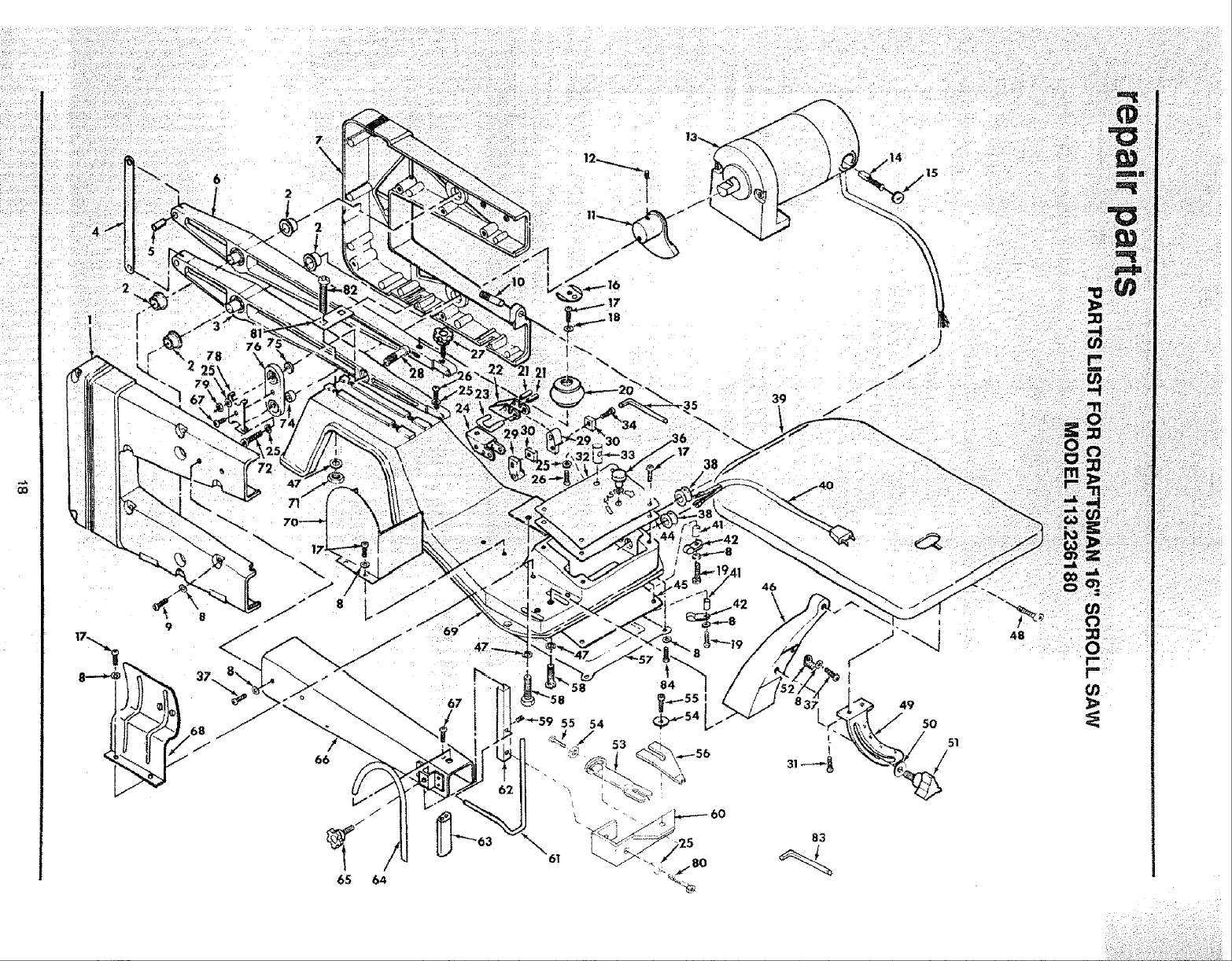
HOW TO ORDER
REPAIR PARTS
!6 tNGH SCROLL SAW
VARIABLE SPEED
ELECTRONIC
Now that you have purchased your Scroll Saw,
should a need ever exist for repair parts or service,
simply contact any Sears Service Center and most
Sears, Roebuck and Co. stores. Be sure to provide
all pertinent facts when you call or visit.
The model number of your Scroll Saw wilt be found
attached to the underside of the worktable.
WHEN ORDERING REPAIR PARTS, ALWAYS
GIVE THE FOLLOWING INFORMATION:
PART NUMBER PART DESCRIPTION
MODEL NUMBER
113.238180
NAME OF ITEM
16 inch Scroll Saw
Variable Speed
Electronic
All parts listed may be ordered from any Sears
Service Center and most Sears stores. If the parts
you need are not stocked locally, your order will be
electronically transmitted to aSears Repair Parts
Distribution Center for handling.
Sold by SEARS, ROEBUCK AN[} CO., Chicago, IL. 60684 U.S.A.
Part No. SP5367 Form No. SP5367-3 Printed in Taiwan lO/92
