Craftsman 113248211 User Manual 12 BAND SAW Manuals And Guides L0709235
CRAFTSMAN Saw Band Manual L0709235 CRAFTSMAN Saw Band Owner's Manual, CRAFTSMAN Saw Band installation guides
User Manual: Craftsman 113248211 113248211 CRAFTSMAN 12 BAND SAW - Manuals and Guides View the owners manual for your CRAFTSMAN 12 BAND SAW #113248211. Home:Tool Parts:Craftsman Parts:Craftsman 12 BAND SAW Manual
Open the PDF directly: View PDF ![]() .
.
Page Count: 48
Iv
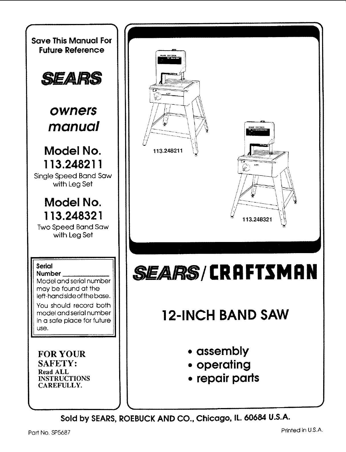
Save This Manual For
Future Reference
_ARS
owners
manual
Model No.
113.248211
Single Speed Band Saw
with Leg Set
Model No.
113.248321
Two Speed Band Saw
with Leg Set
Serial
Number
Model and serial number
may be found at the
left-hand side of the base.
You should record both
model and serial number
in a safe place for future
use.
FOR YOUR
SAFETY:
Read ALL
INSTRUCTIONS
CAREFULLY.
113.248211
/
/t _\x
/
/
/
V
113.248321 _i
SEARSI CRRFTSMRN
12-1NCH BAND SAW
,assembly
°operating
°repair parts
Sold by SEARS, ROEBUCK AND CO., Chicago, IL. 60684 U.S.A.
Part No, SP5687 Printed in U.S.A.

FULL ONE YEAR WARRANTY ON CRAFTSMAN BAND SAW
If wlthln one year from the date of purchase, thls Craftsman Saw falls due to a defect in material or
workmanship, Sears wlll repalr It, free of charge.
WARRANTY SERVICE IS AVAILABLE BY SIMPLY CONTACTING THE NEAREST SEARS SERVICE
CENTER/DEPARTMENT THROUGHOUT THE UNITED STATES.
Thls warranty applies only while thls product Is used In the United States.
Thla warranty gives you specific legal rights and you may also have other rlghts whlch vary from state
to state.
SEARS, ROEBUCK AND CO., D/817 WA Hoffman Estates, IL. 60195
TABLE OF CONTENTS
Section Title Page Number
Safety Instructions for Band Saw ............................... 2
Glossary of Terms for Woodworking .......................... 6
Electrical Connections ................................................ 6
General Information ................................................... 8
Model Description .................................................. 8
Unpacking and Checking Contents ............................ 8
Assembly and Alignment .......................................... 11
Assembling Leg Set ............................................. 11
Adjusting Leveling Feet ....................................... 13
Attaching the Handwheel ..................................... 13
Mounting the Motor .............................................. 14
Connecting the Motor........................................... 17
Selecting Blade Speed ........................................ 18
Recommended Speed Settings ........................... 18
Changing Speed Settings .................................... 18
AttachingTrim Caps ............................................ 18
Getting to Know Your Band Saw .............................. 19
Installingthe Blade .............................................. 20
Aligningthe Blade and
Blade Guide Assemblies ............... .,................ 22
Mounting the Front Table ..................................... 24
Squaring the Blade to the Table .......................... 26
Adjusting Front Table ........................................ ,.. 26
Location and Function of Controls ........................... 27
On-Off Switch ....................................................... 27
Tilting Head for Bevel Cut .................................... 27
Adjusting Bevel Lock Knob .................................. 27
Basic Band Saw Operation ...................................... 28
Circle Cutting ....................................................... 31
Sawdust Collection .............................................. 31
Installing Sand ing Attach me nt ............................. 32
Installing the Sanding Belt ................................... 32
Installing 1/16" Blade and
Blade Guides ................................................... 33
Scrolling ............................................................... 34
Recommended Accessodes .................................... 36
Maintenance ............................................................. 36
Trouble Shooting- All Models .................................. 37
Trouble Shooting - Motor ......................................... 38
Parts Lists ................................................................ 40
Drive Assembly .................................................... 40
Base Components ............................................... 42
Bevel Drive and Motor Mount
Assembly Parts ................................................ 44
Leg Set ................................................................ 46
Safety Instructions for Band Saw
SAFETY SIGNAL WORDS
DANGER: means if the safety information is not fol-
lowed someone will be seriously injuredor killed.
WARNING: means if the safety information is not
followed someone could be seriously injured or killed.
CAUTION: means if the safety information is not fol-
lowed someone might be injured.
Safety is a combination of common sense, staying alert
and knowing how your band saw works. Read this
manual to understand this saw.
BEFORE USING THE SAW:
WARNING: To avoid mistakes that could cause i
i
serious, permanent Injury, do not plug the saw in I
until the following steps are completed.
• Assembly and alignment. (See pages 11 - 18)
•Learn the use and function of the ON-OFF switch,
bevel handwheel, bevel lock knob, blade guides,
backup beatings, guide bar lock knob, and blade
guard (See page 19.)
• Review and understanding of all safety instructions
and operating procedures in is manual.
•Review of the maintenance methods for this saw.
(See page 36.)
Read the following WARNING labels found on the front
of the saw:
I '" I
1. Pma_e'm_ tmf_'eo_:_11w, 6. Oo r'_ mm_4 j,m_t_l eJ,eJlf p,_me_J_JI t Tw,__ _1e*_dv,_ _ b4_v b _
WHEN INSTALLING OR MOVING
THE SAW
AVOID DANGEROUS ENVIRONMENT. Usethe saw in
a dry, indoor place protected from rain. Keep work area
well lighted.
To avoid injury from unexpected saw movement:
•Put the saw on a firm level surface where there is
plenty of room for handling and properly supporting
lhe workpiece.
•Support the saw so the table is level andthe saw does
not rock,
Bolt tile saw to the floor or work surface if it tends to
slip, walk, or slide during operations like cutting long,
heavy boards.
Tu rn saw off and unplug cord before moving the saw.
To avoid injury or death from electrical shock:
GROUND THE SAW. This saw has an approved 3-
conductor cord and a 3-prong grounding type plug.
Use only 3-wire grounded outlets rated 120 volts, 15
amperes (amps). The green conductor in the cord is
the grounding wire. To avoid electrocution, NEVER
connect the green wire to a live terminal.
• Make sure your fingers do not touch the plug's metal
prongs when plugging or unplugging the saw.
To avoid back injury, get help or use recommended
casters when you need to move the saw. Always get
help il you need to lilt the saw.
NEVER STAND ON TOOL. Serious injury could occur
if the tool tips or you accidentally hit the cutting tool. Do
not store anything above or near the tool where anyone
might stand on the tool to reach them.
BEFORE EACH USE:
Inspect your saw.
DISCONNECTTHE SAW. To avoid injury from acciden-
tal starting, unplug the saw, turn the switch off and
remove the switch key before changing the setup, re-
moving covers, guards, blade or sanding belt.
CHECK DAMAGED PARTS. Check for:
• alignment of moving parts,
•binding of moving parts,
w
broken parts,
stable mounting, and
any other conditions that may affect the way the saw
works
If any part is missing, bent, or broken in any way, or any
electrical parts don't work properly, turn the saw oil and
unplug the saw. REPLACE damaged, missing, or failed
parts before using the saw again.
MAINTAIN TOOLS WITH CARE. Keep the saw clean
for best and safest performance. Follow inslructions for
lubricating.
REMOVE ADJUSTING KEYS AND WRENCHES from
tool before turning it on.
To avoid injury from jams, slips or thrown pieces or
broken blades:
• Use of right blade size, style and cutting speed forthe
material and the type of cutting you plan to do.
USE ONLY RECOMMENDEDACCESSORIES. (See
page 36.) Consult this Owner's manual for recom-
mended accessories. Follow the instructions that
come with the accessories. The use of improper
accessories may cause risk of injury to persons.
Make sure lhe blade teeth point downward, toward
the table.
Make sure the blade guides and thrust bearings are
properly adjusted.
• Make sure the blade or sanding belt tension is prop-
erly adjusted.
• Before sanding, adjust the sanding platento clearfhe
table by no more than !/8 of an inch
• Make sure the bevel clamp is tight and no parts have
excessive play.
To avoid accidental blade contact, minimize blade
breakage and provide maximum blade suppo_l, al-
ways adjust fhe upper blade guide and blade guard to
just clear the workpiece.
KEEP WORK AREA CLEAN. Cluttered areas and
benches invite accidents. Floor must not be slippery.
To avoid burns or other fire damage, never use ;he saw
near flammable liquids, vapors or gases.

Plan ahead to protect your eyes, hands,
face and ears.
KNOW YOUR SAW. Read and understand the owner's
manual and labels affixed to the tool. Learn its applica-
tion and limitations as well as the specific potential
hazards peculiar to this tool.
To avoid injury from accidental contact with moving
parts, don't do layout, assembly, or set up work on the
saw while any parts are moving.
AVOIDACCIDENTALSTARTING. Make sure switch is
"OFF" before plugging saw into a power outlet.
Plan your work.
• USE THE RIGHT TOOL. Don't force tool or attach-
ment to do a job it was not designed to do.
• Use model 113.248211 to cut and sand only wood,
wood like products, and plastics.
ICAUTION: To avoid blade breakage, fire or other
damage to the saw, NEVER use model 113.248211
to cut metals.
• Use model 113.248321 to cut and sand only wood,
wood like products, plastics and non-ferrous metals.
CAUTION: Models 113.248321 is NOT designed
for cutting or sanding ferrous metals like iron or
steel. When cutting or sanding non-ferrous met-
als (brass, copper and aluminum, etc.), metal
shavings can react with wood dust and start afire.
To avoid this:
•Disconnect any type of dust collecting hose
from the saw.
•Remove all traces of wood dust from inside the
saw.
• Remove all metal shavings from inside the saw
before sawing wood again.
Dress for safety.
WEAR YOUR
Any power saw can throw foreign objects into the eyes.
This can cause permanenl eye damage. Wear safety
goggles (not glasses) that comply with ANSI Z87.1
(shown on package). Everyday eyeglasses have only
impact resistant lenses. They are not safety glasses.
Safety goggles are available at Sears retail catalog
stores. Glasses or goggles not in compliance with ANSI
Z87.1 could seriously hurt you when they break.
o Do not wear loose clothing, gloves, neckties or jew-
elry (rings, wrist watches). They can get caught and
draw you into moving parts.
•Wearnonslip footwear.
•Tie backlong hair.
Roll long sleeves above the elbow.
Noise levels vary widely. To avoid possible hearing
damage, wear ear plugs or muffs when using saw for
hours at a time.
For dusty operations, weara dust mask along with the
safety goggles.
Inspect your workpiece.
Make sure there are no nails or foreign objects in the
part of the workpiece to be cut.
Use extra caution with large, very small or awkward
workpleces:
•Use extra supports (tables, saw horses, blocks, etc.)
for any workpieces large enough to tip when not held
down to the table lop.
NEVER use another person as a subslitule for a tab!e
extension, or as additional support for a workpiece
thai is longer or wider than the basic saw table, orto
help feed, support or pull the workpiece.
When cutting irregularly shaped workpieces, plan
your work so it will not pinch the blade. A piece of
molding, for example, must lay flat or be held by a
fixture or jig thal will not lel it twist, rock or slip while
being cut.
Properly support round material such as dowel rods,
or tubing. They have a tendency to roll during a cut,
causing the blade to "bite". To avoid this, always use
a"V" b!ock or clamp the work to the miter gage.
Cut only one workpiece at a time.
• CleareverythingexcepttheWorkpieceand related
support devices off the table before turning the saw
013.
Plan the way you will hold the workpiece from start
to finish.
Do not hand hold pieces so small that your fingers will go
under the blade guard. Use jigs or fixtures to hold the
work and keep your hands away from the blade.
SECURE WORK. Use clamps to hold work when
practical. It's often safer than using you r hand, and flees
both hands to operate the toot.
Avoid awkward operations and hand positions where a
sudden slip could cause fingers or hand to move into the
blade or sanding surface.
DON'T OVERREACH. Keep good footing and balance.
WHENEVER SAW IS RUNNING.
WARNING: Don't let familiarity (gained from fre-
quent use of your band saw) cause a careless
mistake. A careless fraction of a second is enough
to cause a severe Injury.
Before starting your cut, watch the saw while it runs. If
it makes an unfamiliar noise or vibrates a lot, stop
immediately. Turn the saw off. Unplug the saw. Do not
restart until finding and correcting the problem.
KEEP CHILDREN AWAY. Keep all visitors a safe
distance from the saw. Make sure bystanders are clear
of the saw and workpiece.
DON'T FORCE TOOL It will do the job better and safer
at its designed rate. Feed the workpiece into the saw
blade only fast enough to let it cut without bogging down
or binding.
Before freeing anY jammed material:
•Tum switch "OFF".
•Remove switch key.
•Unplug the saw.
•Wait for all moving parts to stop.
When backing up theworkpiece, the blade may bind
in the kerf (cut). This is usually caused by sawdust
clog glng up t he kerr or because the blade comes out
of the guides, if this happens:
• Turn switch "'OFF".
Remove switch key.
Unplug saw.
Wait for all moving parts to stop.
Remove band saw cover.
Stick flat blade screwdriver or wedge into the kerl.
Turn the upper wheel by hand while backing up the
workpiece.
Before removing loose pieces from the table, turn saw
off and wait for all moving parts to stop.
BEFORE LEAVING THE SAW:
Wait for all moving parts to stop.
Makeworkshop child-proof. Lockthe shop, Disconnect
master switches. Remove the yellow switch key. Store
it away from children and others not qualified to use the
tool.

glossary of terms for woodworking
BOTH MODELS
Beveling
An angle cutting operation through the face of the
board.
Crosscut
A cutting operation made across the width of the
workpiece.
Compound Cutting
A simultaneous bevel and miter cutting operation,
FPM
Feet per minute. Used in reference to surface speed
of blade.
Freehand (as used for band saw)
Performing a cut without the workpiece properly
supported on the work table.
Gum
A sticky, sap based residue from wood products.
Kerr
The material removed by the blade in a through cut
or the slot produced by the blade in a non-through or
partial cut.
Leading End
The end of the workpiece which is pushed into the
cutting toot first.
Mitering
An angle cutting operation made across the width of
the workpiece.
Push Stick
A device used to feed the workpiece through the saw
during narrow ripping type operations so the opera-
tor's hands are kept well away from the blade.
Resaw
A cutting operation to reduce the thickness of the
workpiece to make thinner pieces.
Resin
A sticky, sap based substance that has dried.
Ripping
A cutting operation along the length of the work-
piece.
Sawblade Path
The area of the worktable or workpiece directly in
line with the saw blade,
Set
The distance the tip of the saw blade tooth is bent
outward from the face of the blade.
Trailing End
The workpiece end last cut by the saw blade.
Workpiece
The item on which the cutting operation is being
performed. The surfaces of a workpiece are commonly
referred to as faces, ends, and edges.
Worktable
The surface on which the workpiece rests while
performing a cutting or sanding operation.
electrical connections
BOTH MODELS
POWER SUPPLY
Motor Specifications
The A-C motor used inthis saw is a capacitor-start, non-
reversible type having the following specifications:
113.248321 113248211
Rated H.P ........................................ 5/8 ........... 1/2
Maximum Developed H.P .............. 1-1/8 ........... 1
Voltage ............................................ 120 .......... 120
Amperes .......................................... 7.9 ........... 7.9
Hertz (Cycles) .................................. 60 ............ 60
Phase ............................................ Single ...... Single
RPM ............................................... 1725 ........ 1725
Rotation of Shaft ........................... Clock-. ..... Clock-
wise wise
WARNING: To avoid electrical hazards, fire haz-
ards, or damage to the tool, use proper circuit
protection. Your saw Is wired at the factory for
120v operetio n. Connect to a 120v, 15-amp, branch
circuit and use a 15-amp fuse or circuit breaker.
WARNING: To avoid shock or tire, If power cord
Is worn or cut, or damaged In any way, have it
replaced Immediately.
WARNING: If not properly grounded this power
tool can cause electrical Shock- particularly when
used In damp locations close to plumbing. If an
electrical shock occurs there Is also the potential
of a secondary hazard such as your hands con-
tacting the sawblade. Not all outlets are properly
grounded. If you are not sure that your outlet is
properly grounded, have It checked by a qualified
electrician.
Your unit has a plug that looks like the one shown below.
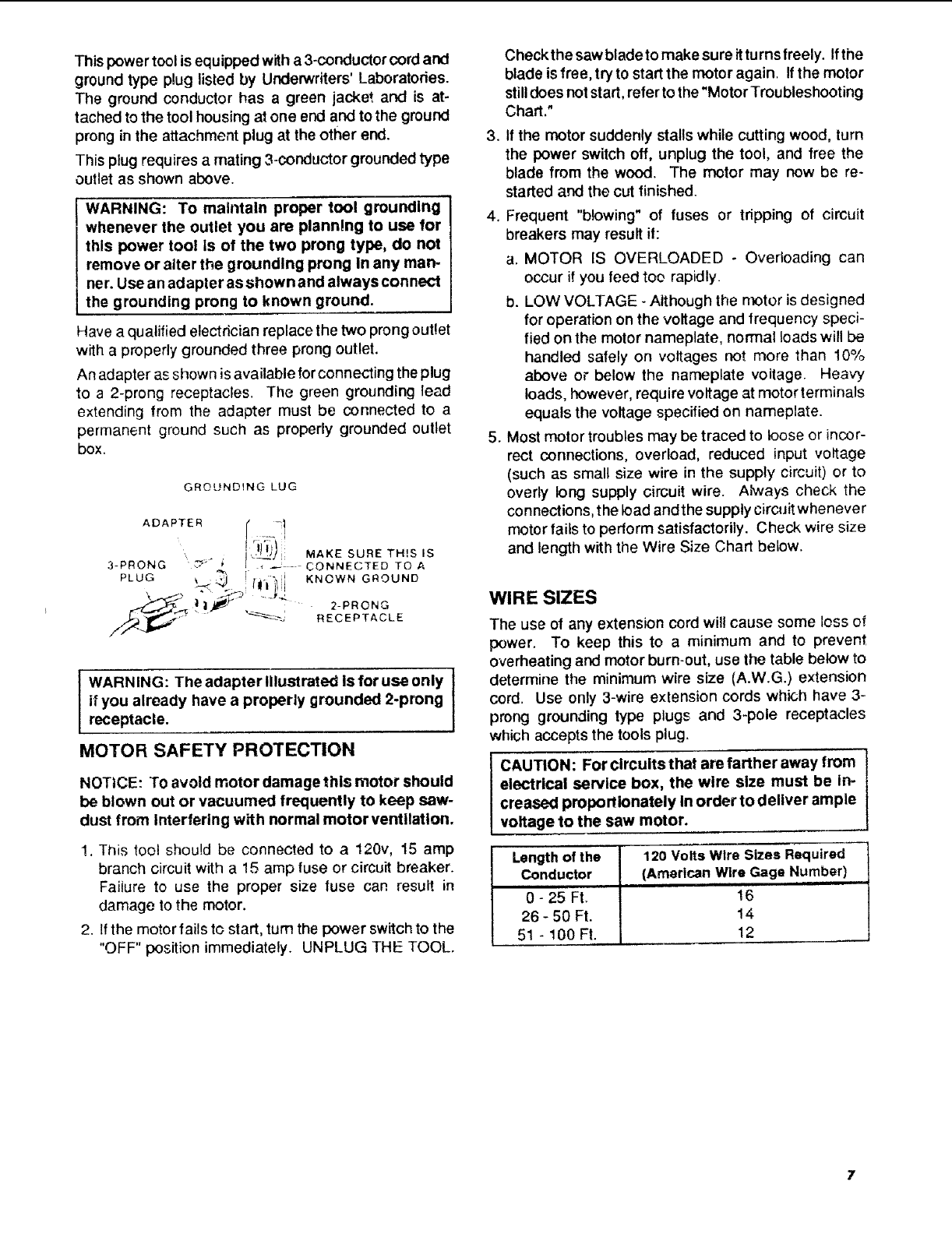
Thispowertool is equipped with a 3-conductor cord and
ground type plug listed by Underwriters' Laboratories.
The ground conductor has a green jacket and is at-
tached to the tool housing at one end and to the ground
prong in the attachment plug at the other end.
This plug requires a mating 3-conductor grounded type
outlet as shown above.
WARNING: To maintain proper tool grounding
whenever the outlet you are planning to use for
this power tool Is of the two prong type, do not
remove or alter the grounding prong in any man-
ner. Use an adapter as shown and always connect
the grounding prong to known ground.
Have a qualified electrician replace the two prong outlet
with a properly grounded three prong outlet.
An adapter as shown is available for connecting the plug
to a 2-prong receptacles. The green grounding lead
extending from the adapter must be connected to a
permanent ground such as properly grounded outlet
box.
GROUNDING LUG
ADAPTER
PLUG _
MAKE SURE TH!S IS
-, _ - CONNECTED TO A
KNOWN GROUND
I WARNING: The adapter Illustrated Is for use only I
if you already have a properly grounded 2-prong I
receptacle.
MOTOR SAFETY PROTECTION
NOTICE: To avoid motor damage this motor should
be blown out or vacuumed frequently to keep sew-
dust from Interfering with normal motor ventilation.
1. This tool should be connected to a 120v, 15 amp
branch circuit with a 15 amp fuse or circuit breaker.
Faiiure to use the proper size fuse cap, resui_ in
damage to the motor.
2. If the motor faUs to start, turn the power switch to the
"OFF" position immediately. UNPLUG THE TOOL.
Checkthe saw bladeto make sure it turns freely. Ifthe
blade is free, try to start the motor again. If the motor
stilldoes not start, refer to the "Motor Troubleshooting
Chart."
3. If the motor suddenly stalls while cutting wood, turn
the power switch off, unplug the tool, and free the
blade from the wood. The motor may now be re-
started and the cut finished.
4. Frequent "b!owing" of fuses or tripping of circuit
breakers may result if:
a. MOTOR IS OVERLOADED - Overloading can
occur if you teed too rapidly.
b. LOW VOLTAGE - Although the motor is designed
for operation on the voltage and frequency speci-
fied on the motor nameplate, normal loads will be
handled safely on voltages not more than 10%
above or below the nameplate voltage. Heavy
loads, however, require voltage at motor terminals
equals the voltage specified on nameplate.
5. Most motor troubles may be traced to loose or incor-
rect connections, overload, reduced input voltage
(such as small size wire in the supply circuit) or to
overly long supply circuit wire. AM,ays check the
connections, the load and the supply circuit whenever
motor fails to perform satisfactorily. Check wire size
and length with the Wire Size Chart below.
WIRE SIZES
The use of any extension cord will cause some loss of
power. To keep this to a minimum and to prevent
overheating and motor burn-out, use the table below to
determine the minimum wire size (A.W.G.) extension
cord. Use only 3-wire extension cords which have 3-
prong grounding type plugs and 3-pole receptacles
which accepts the tools plug.
CAUTION: For circuits that are farther away from
electrical service box, the wire size must be In-
creased proportionately In order to deliver ample
voltage to the saw motor.
Length of the 120 Volts Wire Sizes Required
Conductor (American Wire Gage Number)
0 - 25 Ft. 16
26 - 50 Ft. 14
51 - 100 Ft. 12
7
general information
BOTH MODELS
1. This manual is 1orthe following Models - 113.248211
and 113,248321. All sections are labeled with the
correct model number. Follow ONLY instructions
that are meant for your model saw.
2. If you are missing anypart(s) while putting your saw
together, do not continue assembly. Contact your
Sears Service Center or Retail Store and get the
missing part(s) before continuing assembly or trying
to use the saw.
Complete parts lists are located at the end of this
manual. Use these liststo identifythe number of any
missing part.
3. Sometimes small parts get lost in packaging materi-
als. Do not throw away any packaging until your saw
is put logether. If you are missing a part, check
packaging before contacting Sears.
MODEL DESCRIPTION
MOdel 113.248211: Manual Band Saw; 18 x 23 inch
Work table; single speed; 1/2 HP. motor that develops
1 H.P.; legset.
Model 113. 248321: Manual Band Saw; 27 x 23 inch
work table; two speed; 5/8 HP. motor that develops
1-1/8 H.P.; legset.
unpacking and checking contents
BOTH MODELS
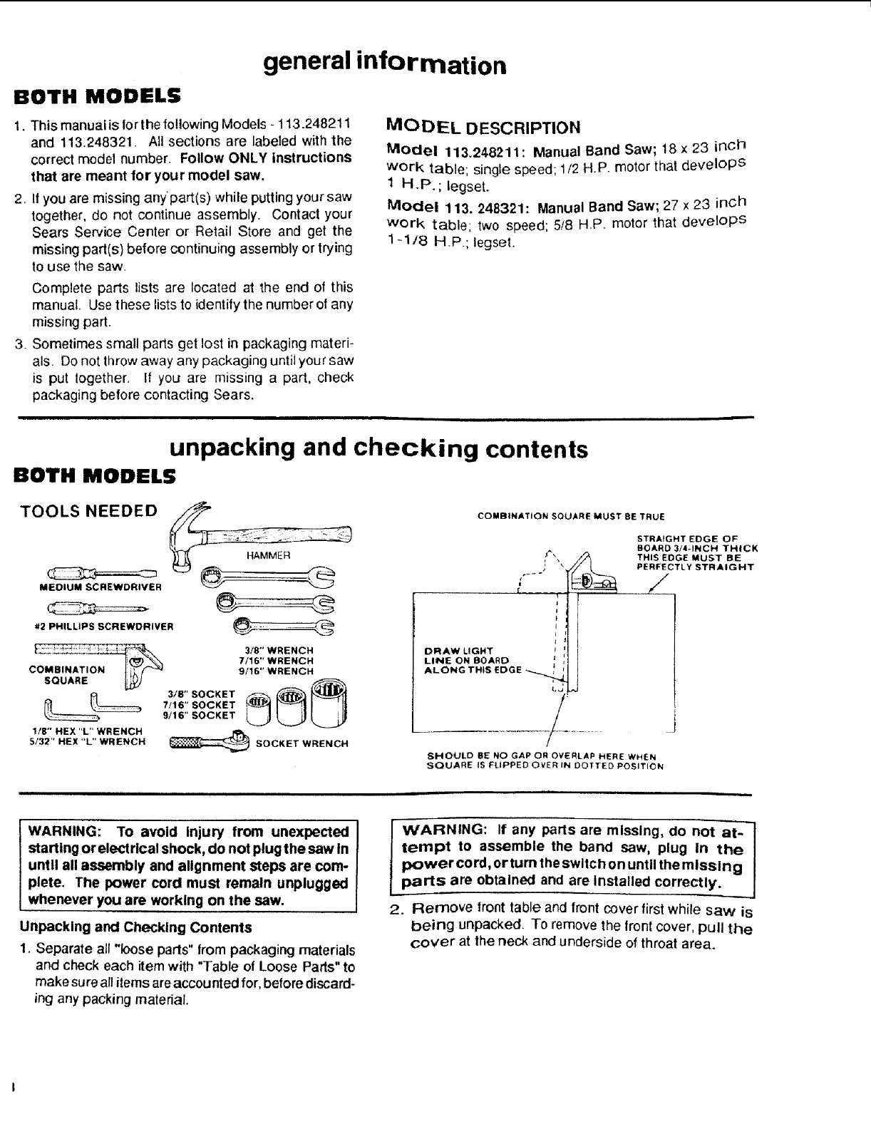
TOOLS NEEDED
MEDIUM SCREWDRIVER
_' _....... 3/8" WRENCH
7/16" WRENCH
COMBINATI 9/16" WRENCH
SQUARE_
7/16" SOCKET
9/16" SOCKET
1/8" HEX "L" WRENCH R_
5/32" HEX "L" WRENCH _SOCKET WRENCH
COMBINATION SQUARE MUST BE TRUE
f
STRAIGHT EDGE OF
BOARD 3/4-INCH THICK
THIS EDGE MUST BE
PE_CTLY STRAIGHT
DRAW LIGHT
LINE ON BOARD
ALONGTHIS EDGE _,,_ J
SHOULD BE NO GAP OR OVERLAP HERE WHEN
SQUARE IS FLIPPED OVER IN DOTTED POSITION
WARNING: To avoid Injury from unexpected
starting or elect rical shock, do not plug the saw in
until all assembly and alignment steps are com-
plete. The power cord must remain unplugged
whenever you are working on the saw.
Unpacking and Checking Contents
1. Separate all "loose parts" from packaging materials
and check each item with "Table of Loose Parts" to
make sure all items are accounted for, before discard-
ing any packing material.
lWARNING: If any parts are missing, do not at-
tempt to assemble the band saw, plug in the
power cord, or turn the switch on until the missing
parts are obtained and are installed correctly.
2. Remove front table and front cover first while saw is
being unpacked. To remove the front cover, pull the
cover at the neck and underside of throat area.
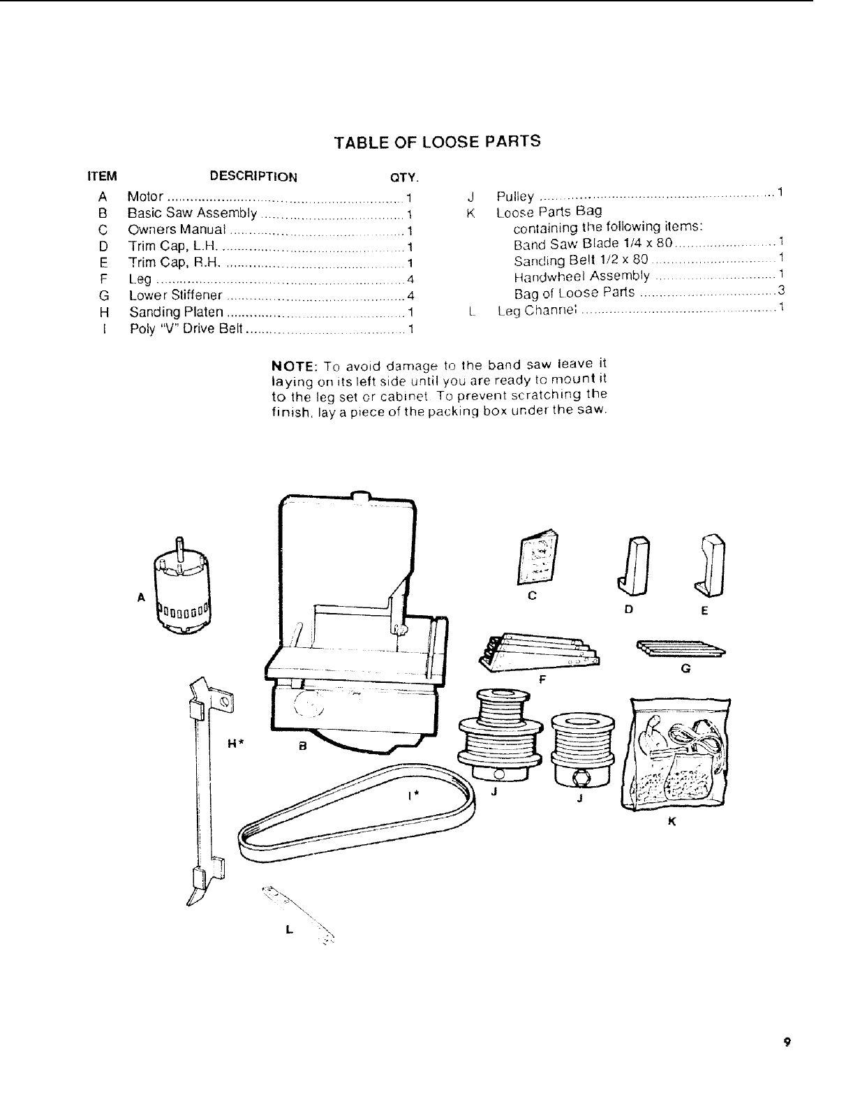
TABLE OFLOOSEPARTS
ITEM DESCRIPTION QTY.
A Motor ............................................................. 1
B Basic Saw Assembly ................................... 1
C Owners Manual ........... .................................. 1
D Trim Cap, LH ............................................... 1
E Trim Cap, R.H .............................................. 1
F Leg ................................................................ 4
G Lower Stiffener ............................................ 4
H Sanding Platen ............................................. 1
I Poly "V" Drive Belt ...................................... 1
J Pulley ........................................................... 1
K Loose Parts Bag
containing tile following items:
Band Saw Blade 1/4 x 80 ........................ 1
Sanding Be!l 1/2 x 80 ............................. 1
Handw,heel Assembly ............................ I
Bag of Loose Parts ............................... 3
L Leg C hanr}e', ............................................. 1
NOTE: To avoid damage to the band saw leave it
laying on its left side until you are ready to mount it
to the leg set or cabinet To prevent scratching the
finish, lay a p_ece of the packing box under the saw.
A
D
F
J
E
K
BOTH MODELS
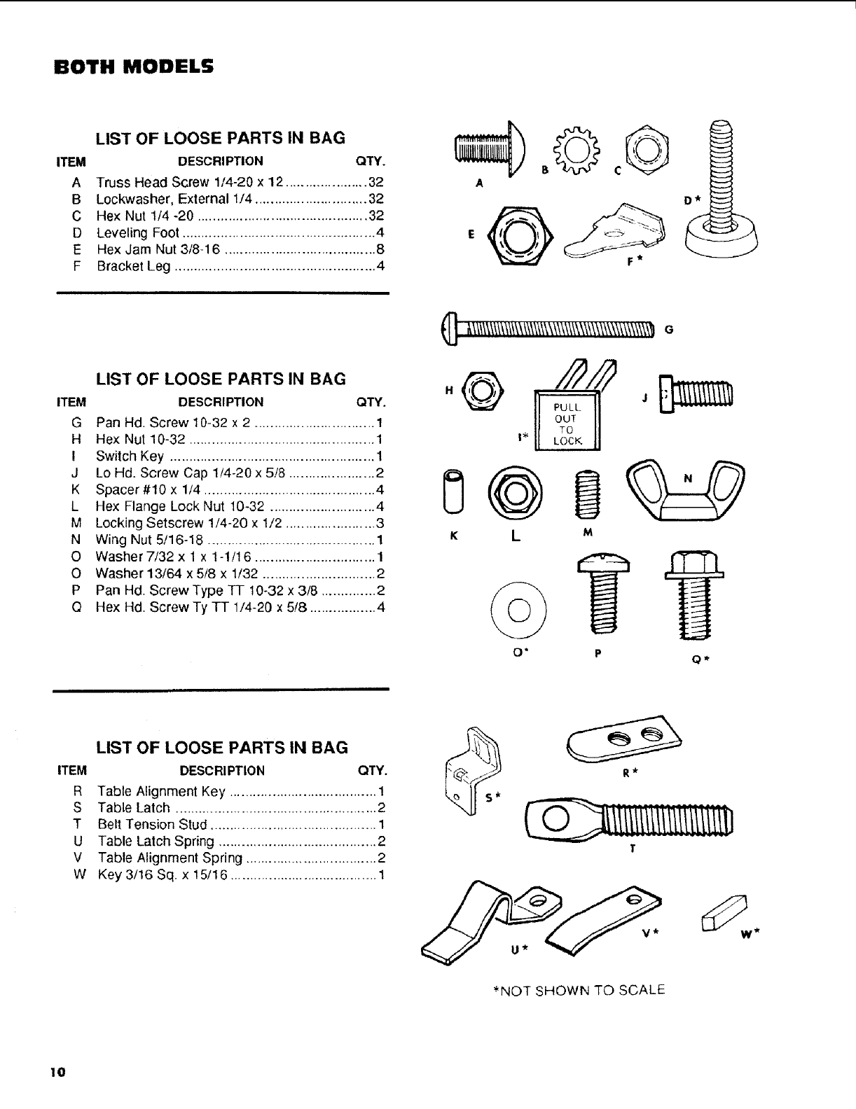
LIST OF LOOSE PARTS IN BAG
ITEM DESCRIPTION QTY.
A Truss Head Screw 1/4-20 x 12 ..................... 32
B Lockwasher, External 1/4 ............................. 32
C Hex Nut 1/4 -20 ............................................ 32
D Leveling Foot .................................................. 4
E HexJam Nut3/8-16 ....................................... 8
F Bracket Leg .................................................... 4
A
Dllr
LIST OF LOOSE PARTS IN BAG
ITEM DESCRIPTION QTY.
G Pan Hd. Screw 10-32 x 2 ............................... 1
H Hex Nut 10-32 ................................................ 1
I Switch Key ..................................................... 1
J Lo Hd. Screw Cap 1/4-20 x 5/8 ...................... 2
K Spacer#10 x 1/4 ............................................ 4
L Hex Flange Lock Nut 10-32 ........................... 4
M Locking Setscrew 1/4-20 x 1/2 ....................... 3
N Wing Nut 5/16-18 ........................................... 1
O Washer7/32 x 1 x 1-1/16 ............................... 1
O Washer 13/64 x 5/8 x 1/32 ............................. 2
P Pan Hd. Screw Type TT 10-32 x 3/8 .............. 2
Q Hex Hd. Screw Ty TT 1/4-20 x 5/8 ................. 4
([]_\\t;\\\\\\;\\\\\\\\\\\\\\\\\\\\\\\\\\\\\\\\\\\\_e
LIST OF LOOSE PARTS IN BAG
ITEM DESCRIPTION QTY.
R Table Alignment Key ...................................... 1
S Table Latch .................................................... 2
T Belt Tension Stud ........................................... 1
U Table Latch Spring ......................................... 2
V Table Alignment Spring .................................. 2
W Key3/16Sq. x 15/16 ...................................... 1
R_
]-
*NOT SHOWN TO SCALE
I0
assembly and alignment
BOTH MODELS
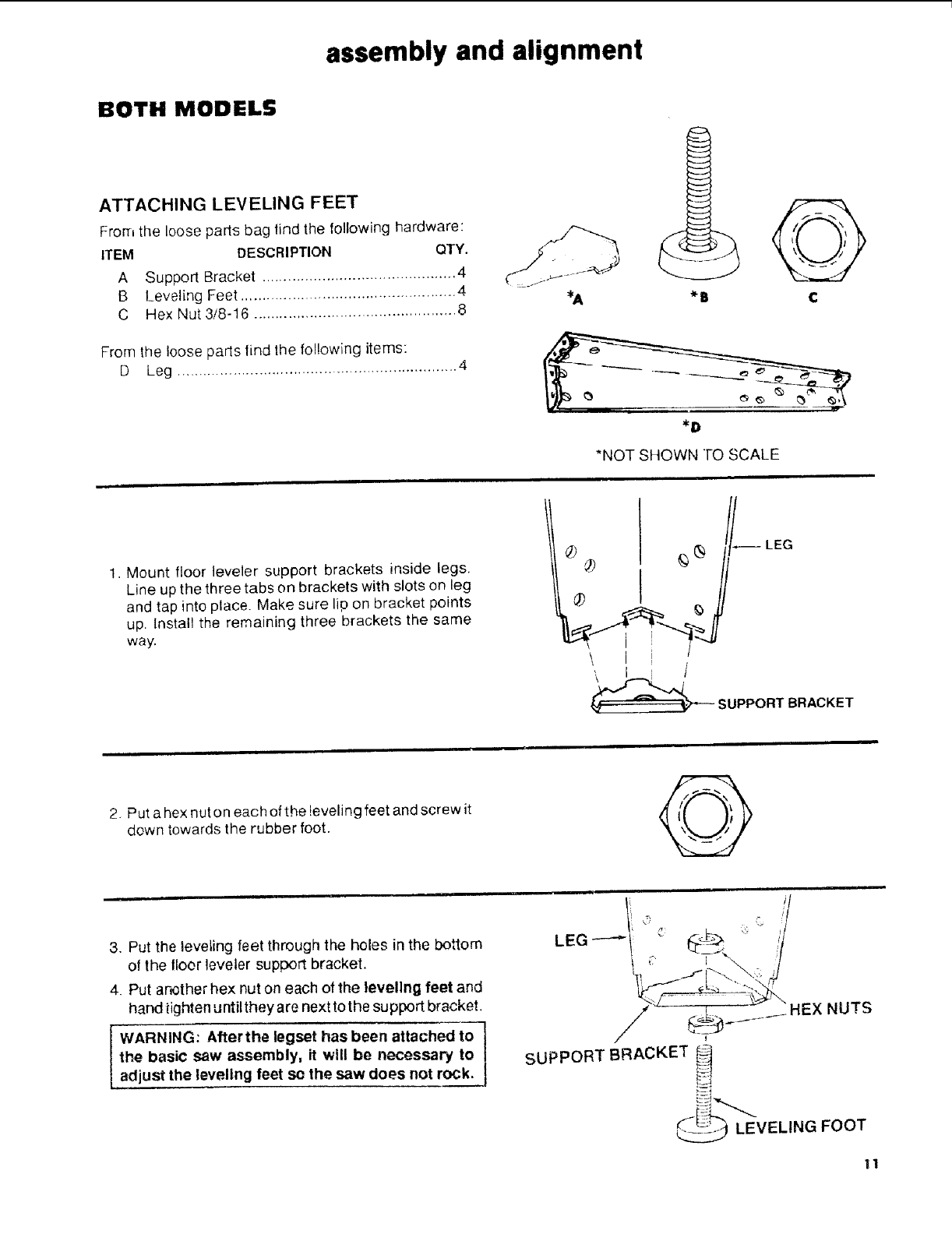
ATTACHING LEVELING FEET
From the loose parts bag find the following hardware:
ITEM DESCRIPTION QTY.
A Support Bracket ............................................. 4
B Leveling Feet .................................................. 4
C Hex Nut 3/8-16 ............................................... 8
From the loose parts find the following items:
D Leg ................................................................. 4
*U
*D
*NOT SHOWN TO SCALE
1. Mount floor leveler support brackets inside legs.
Line up the three tabs on brackels with slots on leg
and tap into place. Make sure lip on bracket points
up. Install the remaining three brackets the same
way.
¢
-- LEG
®="l"
SUPPORTBRACKET
2 Put a hex nut on each of the !eveling feet and screw it
down towards the rubber foot.
3, Put the leveling feet through the holes in the bottom
of the tloor leveler support bracket.
4, Put another hex nut on each of the leveling feet and
hand tighten until they are next to the support bracket.
IWARNING: After the legset has been attached to
the basic saw assembly, it will be necessary to
adjust the leveling feet so the saw does not rock.
EX NUTS
I
SUPPORT BRACKET _
LEVELING FOOT
11
BOTH MODELS
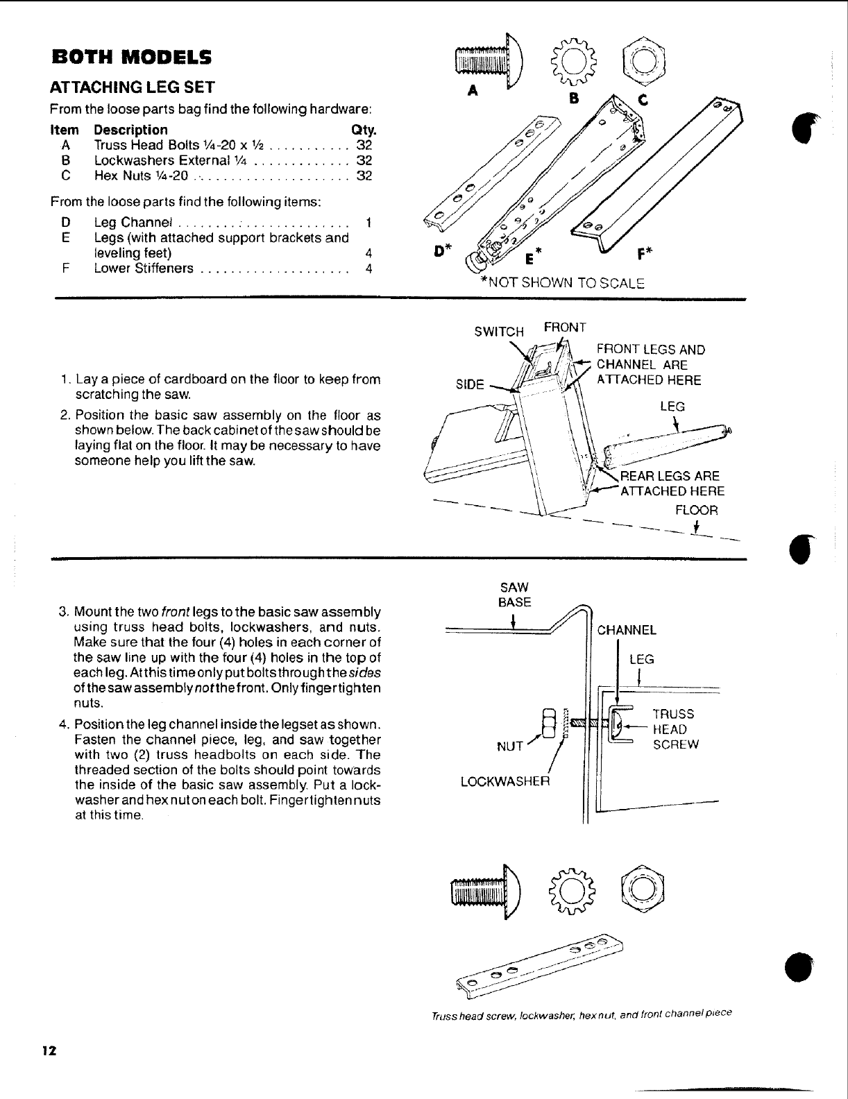
ATTACHING LEG SET
From the loose parts bag find the following hardware:
Item Description Qty.
A Truss Head Bolts 1/4-20 x 1/2........... 32
B Lockwashers External 1/4 ............. 32
C Hex Nuts 1/4-20 ...................... 32
From the loose parts find the following items:
D Leg Channel ........ ............... 1
E Legs (with attached support brackets and
leveling feet) 4
F Lower Stiffeners .................... 4
B¢
E* F_
*NOT SHOWN TO SCALE
,
1. Lay a piece of cardboard on the floor to keep from
scratching the saw.
2. Position the basic saw assembly on the floor as
shown below. The back cabinet of the saw should be
laying flat on the floor. It may be necessary to have
someone help you lift the saw.
SWITCH FRONT
3, Mount the two front legs to the basic saw assembly
using truss head bolts, Iockwashers, and nuts.
Make sure that the four (4) holes in each corner of
the saw line up with the four (4) holes in the top of
each leg, At this time only put bolts through the sides
of the saw assemblynotthe front. Only fingertighten
nuts.
4, Position the leg channel inside the legset as shown.
Fasten the channel piece, leg, and saw together
with two (2) truss headbolts on each side. The
threaded section of the bolts should point towards
the inside of the basic saw assembly Put a lock-
washer and hex nuton each bolt. Fingertighten nuts
at this time.
NUT 7_-_/
LOCKWASHER
FRONTLEGSAND
CHANNEL ARE
A3q-ACHED HERE
LEG
REAR LEGSARE
3HEDHERE
FLOOR
;CHANNEL
LEG
_ TRUSSt_,---HEAD
SCREW
Truss head screw, lockwasher, hex nut, and front channel p_ece
12
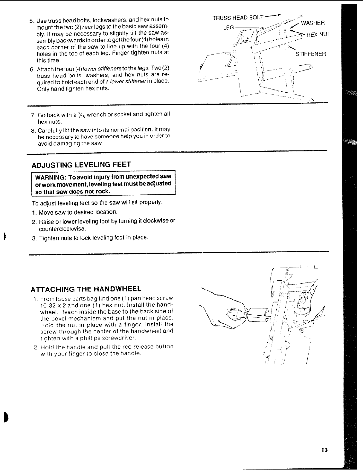
5. Use truss head bolts, Iockwashers, and hex nuts to
mount the two (2) rear legs to the basic saw assem-
bly. It may be necessary to slightly tilt the saw as-
sembly backwards inorder to get the four (4) holes in
each corner of the saw to line up with the four (4)
holes in the top of each leg. Finger tighten nuts at
this time.
6. Attach t he four (4)lower stiffeners to the legs. Two (2)
truss head bolts, washers, and hex nuts are re-
quired to hold each end of a lower stiffener in place.
Only hand tighten hex nuts.
TRUSS HEAD BOLT-'-"--" WASHER
LEG
i,HEX NUT
7. Go back with a 7_6wrench or socket and tighten all
hex nuts.
8. Carefully lift the saw into its normal position. It may
be necessary to have someone help you in order to
avoid damaging the saw.
STIFFENER
ADJUSTING LEVELING FEET
IWARNING: TO avoid injury from unexpected saw I
or work movement, leveling feet must be adjusted
so that saw does not rock.
To adjust leveling feet so the saw will sit properly:
1, Move saw to desired location.
2. Raise or lower leveling foot by turning it clockwise or
counterclockwise.
3. Tighten nuts to lock leveling foot in place.
ATTACHING THE HANDWHEEL
1. From loose parts bag find one (1) pan head screw
10-32 x 2and one (1) hex nut. Install the hand-
wheel. Reach inside the base to the back side of
the bevel mechanism and put the nut in place.
Hold the nut in place with a finger. Install the
screw through the center of the handwheel and
tighten with a phillips screwdriver.
2. Hotd the handle and pu!t the red release button
witil your finger to close the handle.
C,,Cf_,,
,,'!.
i
13
BOTH MODELS
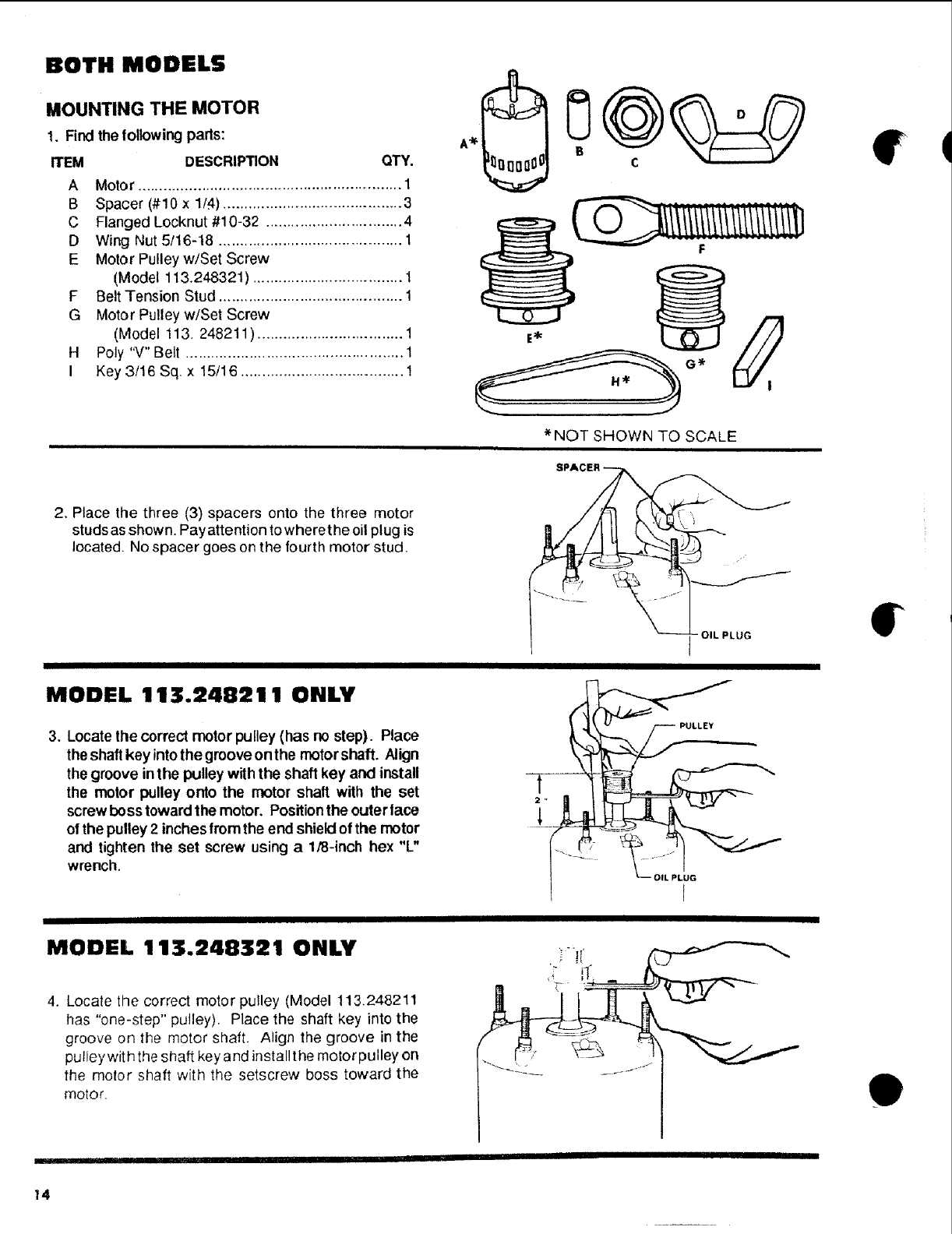
MOUNTING THE MOTOR
1. Findthe following parts:
ITEM DESCRIPTION QTY.
A Motor .............................................................. 1
B Spacer (#10 x 1/4) .......................................... 3
C Flanged Locknut #10-32 ................................ 4
D Wing Nut 5/16-18 ........................................... 1
E Motor Pulleyw/Set Screw
(Model 113.248321) ................................... 1
F Belt Tension Stud ........................................... 1
G Motor Pulleyw/Set Screw
(Model 113. 248211) .................................. 1
H Poly "V" Belt ................................................... 1
I Key 3/16 Sq x 15/16 ...................................... 1
*NOT SHOWN TO SCALE
2. Place the three (3) spacers onto the three motor
studs as shown. Pay attention to where the oil plug is
located, No spacer goes on the fourth motor stud.
MODEL 113.248211 ONLY
3. Locate the correct motor pulley (has no step). Place
the shaft key intothe groove onthe motorshaft. Align
the groove inthe pulley with the shaft key and install
the motor pulley onto the motor shaft with the set
screw boss toward the motor. Positionthe outerlace
of the pulley 2 inches fromthe end shieldof the motor
and tighten the set screw using a 1/8-inch hex "L"
wrench.
PULLEY
OIL PLUG
MODEL 113.248321 ONLY
4. Locate the correct motor pulley (Model 113.248211
has "one-step" pulley). Place the shaft key into the
groove on the motor shaft. Align the groove in the
pulley wit h the shaft key and install the motor pulley on
the motor shaft with the setscrew boss toward the
motor, e
14
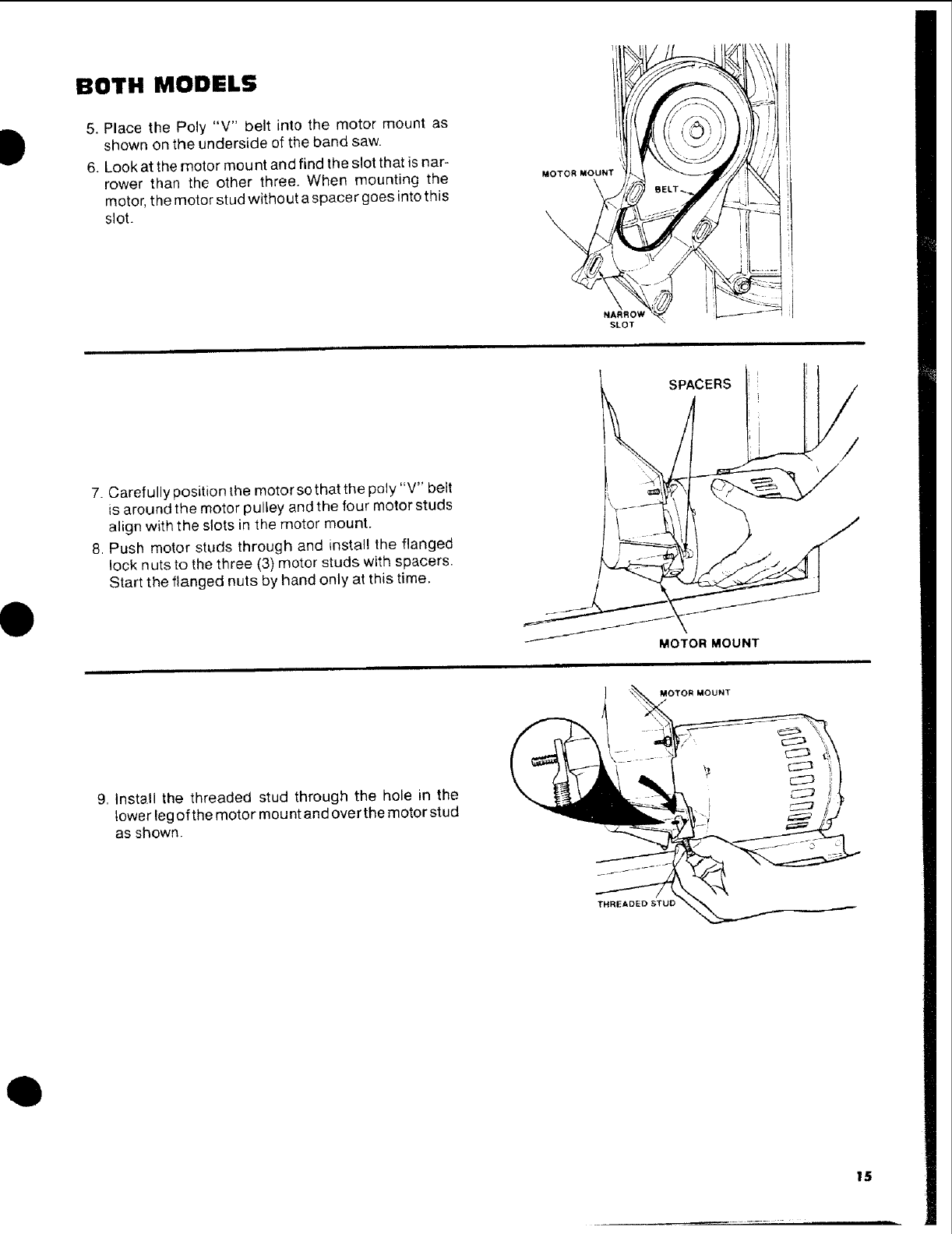
BOTH MODELS
5. Place the Poly "V" belt into the motor mount as
shown on the underside of the band saw.
6. Look at the motor mou nt and find the slot that is nar-
rower than the other three. When mounting the
motor, the motor stud without a spacer goes into this
slot.
MOTOR MOUNT
NARROW
SLOT
7. Carefully position the motor sothat the poly "V" belt
is around the motor pulley and the four motor studs
align with the slots in the motor mount.
8. Push motor studs through and install the flanged
lock nuts to the three (3) motor studs with spacers.
Start the flanged nuts by hand only at this time.
MOTOR MOUNT
9, Install the threaded stud through the hole in the
lower legof the motor mount and over the motor stud
as shown.
THREADED STUD
MOTORMOUNT
/
15
, ,, ......... ,,,==,,
|OTH MODELS
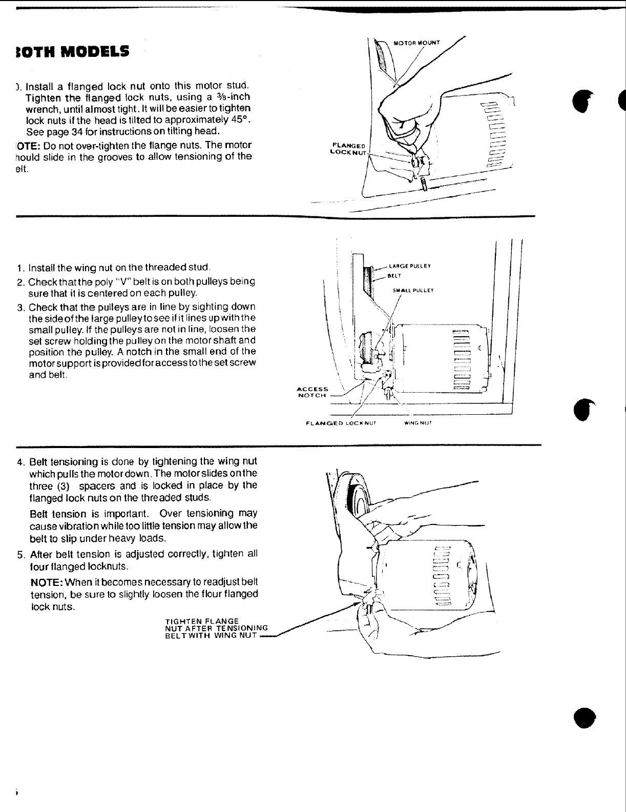
). Install a flanged lock nut onto this motor stud.
Tighten the flanged lock nuts, using a 3/8-inch
wrench, until almost tight. It will be easier to tighten
lock nuts if the head is tilted to approximately 45 °.
See page 34 for instructions on tilting head.
OTE: Do not over-tighten the flange nuts. The motor
_ould slide in the grooves to allow tensioning of the
elt.
FLANGEDI _'-
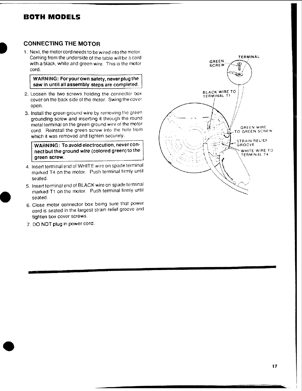
1. Install the wing nut on the threaded stud.
2. Check that the poly "V" belt is on both pulleys being
sure that it is centered on each pulley.
3. Check that the pulleys are in line by sighting down
the sideof the large pulley to see if it lines up with the
small pulley. If the pulleys are not in line, loosen the
set screw holding the pulleyon the motor shaft and
position the pulley. A notch in the small end of the
motor support is provided for access to the set screw
and belt.
l'
ACCESS \
NOTCH
ILLEY
SMALL PULLEY
/
FLANGEO LOCK NUI WING NU! I"
4. Belt tensioning is done by lightening the wing nut
which pulls the motor down. The motorslides onthe
three (3) spacers and is locked in place by the
flanged lock nuts on the threaded studs•
Belt tension is important. Over tensioning may
cause vibration while too little tension may allow the
belt to slip under heavy loads.
5. After belt tension is adjusted correctly, tighten all
four flanged Iocknuts.
NOTE: When it becomes necessary to readjust belt
tension, be sure to slightly loosen the flour flanged
lock nuts.
TIGHTEN FLANGE
NUT AFTER TENSIONING
BELTWITH WING NU'I
e
BOTH MODELS
0
CONNECTING THE MOTOR
1. Next, the motorcord needs to be wired into the motor
Coming from the underside of the table will be acord
with a black, white and green wire This is the motor
cord.
WARNING: Foryourown safety, neverplug the 1
saw in until all assembly steps are completed. ]
2. Loosen the two screws holding the connector box
cover on the back side ot the motor. Swing the cover
open.
3. Install the green ground wire by removing the green
grounding screw and inserting it through the round
metal terminal on the green ground wire of the motor
cord. Reinstall the green screw into the hole from
which it was removed and tighten securely.
41
.
6.
.
WARNING: To avoid electrocution, never con-
nect but the ground wire (colored green) to the
green screw.
Insert terminal end of WHITE wire on spade terminal
marked T4 on the motor. Push terminal firmly until
seated.
Insert terminal end of BLACK wire on spade terminal
marked T1 on the motor. Push terminal firmly until
seated.
Close motor connector box being sure that power
cord is seated in the largest strain relief groove and
tighten box cover screws.
DO NOT plug in power cord.
Q
17
MODEL 113.248321 ONLY
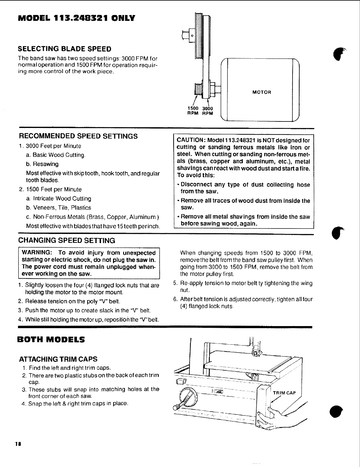
SELECTING BLADE SPEED
The band saw has two speed settings: 3000 FPM for
normaloperation and 1500 FPM for operation requir-
ing more control of the work piece.
i
RECOMMENDED SPEED SETTINGS
1. 3000 Feet per Minute
a. Basic Wood Cutting.
b. Resawing
Most effective with skip tooth, hook tooth,and regular
tooth blades.
2. 1500 Feet per Minute
a. Intricate Wood Cutting
b. Veneers, Tile, Plastics
c. Non-Ferrous Metals (Brass, Copper, Aluminum.)
Most ellective with blades that have 15teeth per inch.
_-]
1500 3000
RPM RPM
MOTOR
J
CAUTION: Model 113.248321 is NOT designed for
cutting or sanding ferrous metals like iron or
steel. When cutting or sanding non-ferrous met-
als (brass, copper and aluminum, etc.), metal
shavings can react with wood dust and start a fire.
To avoid this:
-Disconnect any type of dust collecting hose
from the saw.
•Remove all traces of wood dust from inside the
saw.
• Remove all metal shavings from inside the saw
before sawing wood, again.
CHANGING SPEED SETTING
WARNING: To avoid injury from unexpected
starting or electric shock, do not plug the saw in.
The power cord must remain unplugged when-
ever working on the saw.
1. Slightly loosen the four (4) flanged lock nuts that are
holding the motor to the motor mount.
2. Release tension on the poly "V" belt.
3. Push the motor up to create slack in the "V" belt.
4. While still holding the motor up, repositioh the "V" belt.
I
.
6.
When changing speeds from 1500 to 3000 FPM,
remove the beIt from the band saw pu Iley first. When
going from 3000 to 1500 FPM, remove the belt from
the motor pulley first.
Re-apply tension to motor belt ty tightening the wing
nut.
After belt tension is adjusted correctly, tighten all four
(4) flanged lock nuts.
I
BOTH MODELS
ATTACHING TRIM CAPS
1. Find the left and right trim caps.
2. There are two plastic stubs on the back of each trim
cap.
3. These stubs will snap into matching holes at the
front corner of each saw.
4. Snap the left & right trim caps in place.
TRIM CAP
€
18
getting to know your band saw
O2
1 z_.s,o.ADJUST.E.TK.OB
WA,N,,_.AB_. 4 * 5 6
BEARING
BLADE GUIDES
BLADE GUIDES
6
BACK-UP BEARING
BEVEL SCALE
3
BEVEL LOCK KNOB
MITER GAGE SLOT
O
HAI,IDWHEE L
BOTH MODELS
ON-OFF SWITCH
O
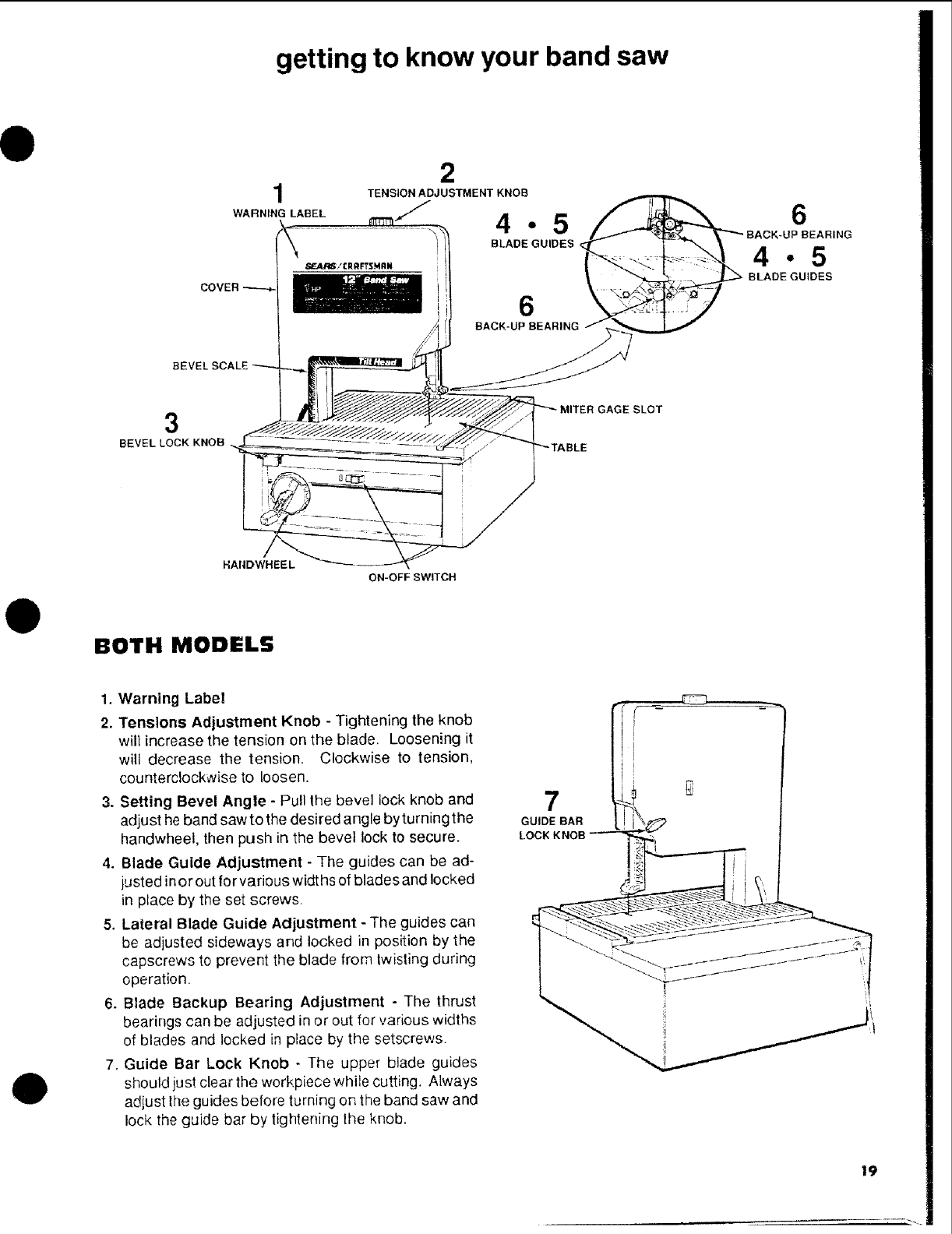
1. Warning Label
2. Tensions Adjustment Knob - Tightening the knob
will increase the tension on the blade. Loosening it
wili decrease the tension. Clockwise to tension,
counterclockwise to loosen.
3. Setting Bevel Angle - Pull the bevel lock knob and
adjust he band saw to the desired angle by turning the
handwheel, then push in the bevel lock to secure.
4. Blade Guide Adjustment - The guides can be ad-
justed in or out for various widths of blades and locked
in place by the set screws.
5. Lateral Blade Guide Adjustment - The guides can
be adjusted sideways and locked in position by the
capscrews to prevent the blade from twisting during
operation.
6. Blade Backup Bearing Adjustment - The thrust
bearings can be adjusted in or out for various widths
of blades and locked in place by the setscrews.
7, Guide Bar Lock Knob -The upper blade guides
should just clear the werkpiece while cutting, Always
adjust the guides before turning on the band saw and
lock the guide bar by tightening the knob.
7
GUIDE BAR _'_
LOCKK.OB--_.!_!___, rr'
19
BOTH MODELS
INSTALLING "I'HE BLADE
WARNING: To avoid Injury from accidental start-
Ing, make sure the power cord is unplugged
before removing any part from the saw.
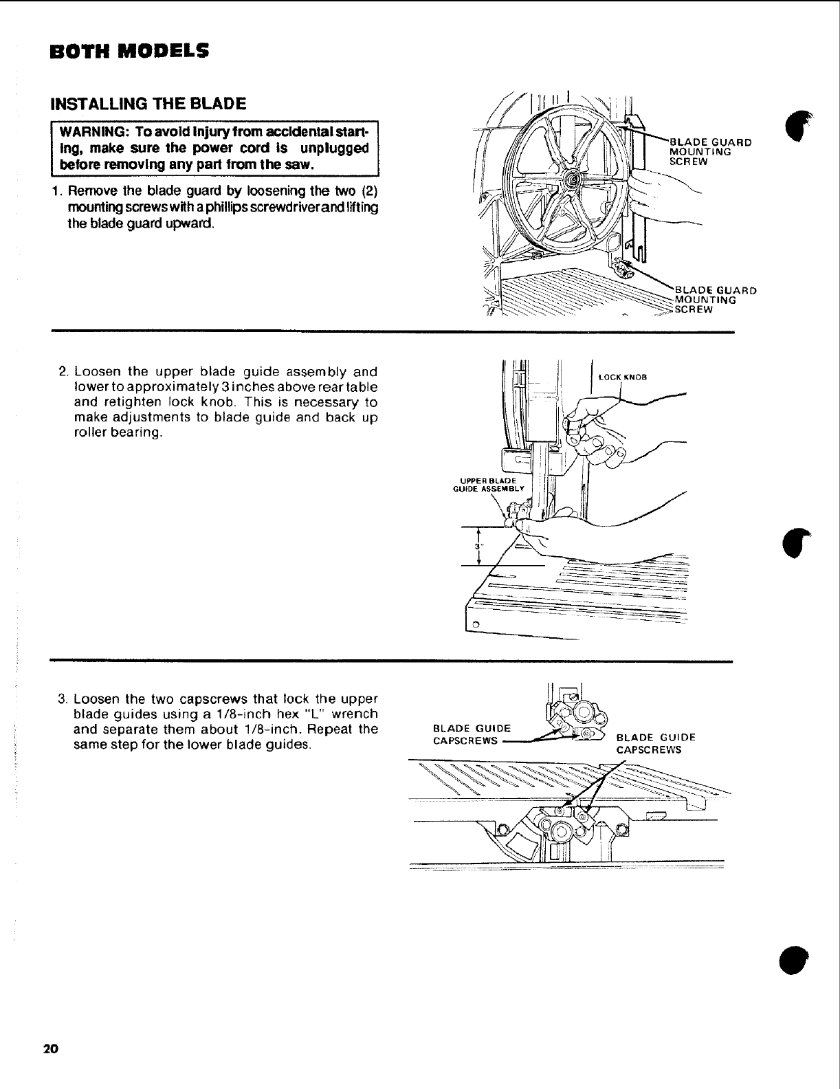
1. Remove the blade guard by loosening the two (2)
mounting screws with a phillips screwdriverand lifting
the blade guard upward,
Ill\
4
_\_ !1 r "_BLADE GUARD
_\'I_FII MOUNT=NG
i' SCREW
GUARD
2. Loosen the upper blade guide assembly and
lower to approximately 3 inches above rear table
and retighten lock knob. This is necessary to
make adjustments to blade guide and back up
roller bearing.
3. Loosen the two capscrews that lock the upper
blade guides using a 1/8-inch hex "L" wrench
and separate them about 1/8-inch. Repeat the
same step for the lower blade guides. BLADE GUIDE
CAPSCREWS
0
2O
t
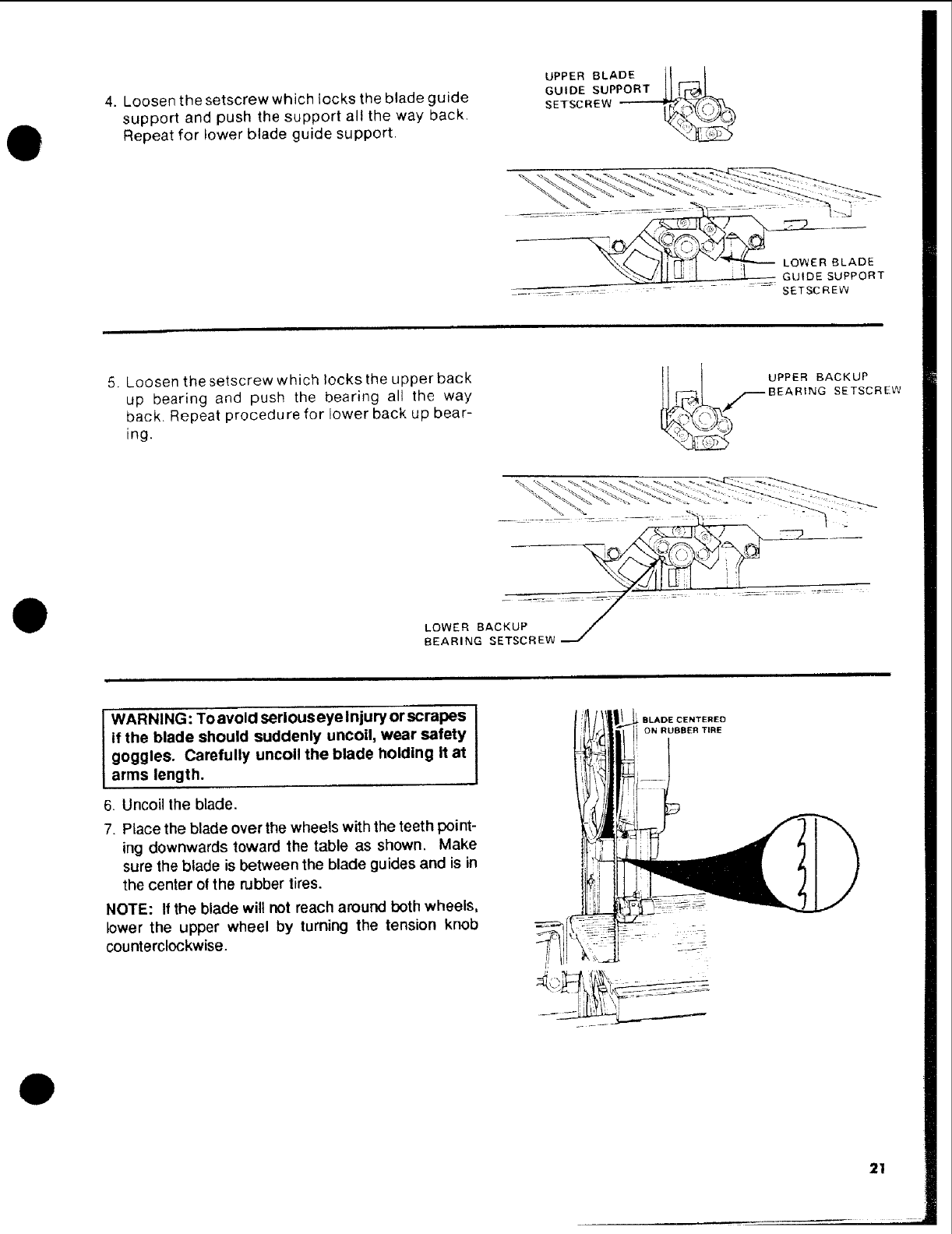
4. Loosen the setscrew which locks the blade guide
support and push the support all the way back.
Repeat for lower blade guide support.
UPPER BLADE /I I
SETSCREW -.----.--,t_*'_
__BLADE
UPPORT
.... _.... -..... .... -SETSCREW
O
5. Loosen the setscrew which locks the upper back
up bearing and push the bearing all the way
back. Repeat procedure for lower back up bear-
ing.
_L,_ UPPER BACKUP
i _i BEARING SETSCREW
LOWER BACKUP .....
BEARING SETSCREW
WARNING: To avoid serious eye Injury or scrapes
if the blade should suddenly uncoil, wear safety
goggles. Carefully uncoil the blade holding it at
arms length.
6. Uncoil the blade.
7. Place the blade over the wheels with the teeth point-
ing downwards toward the table as shown. Make
sure the blade is between the blade guides and is in
the center ot the rubber tires.
NOTE: If the blade will not reach around both wheels,
lower the upper wheel by turning the tension knob
counterclockwise.
BLADE CENTERED
ON RUBBER TIRE
O
21
BOTH MODELS
ALIGNING THE BLADE AND BLADE
GUIDE ASSEMBLIES
This band saw comes equipped with a 1/4-inch blade.
This band saw can be used with blades of width from
1/8-inch to 1/2-inch. The alignment steps must be
followed for proper tension, blade guide, and bearing
adjustments for each different blade.
Refer to the blade usage section for the recommended
blade size for best results during most band saw opera-
tions.
NOTE: It is critical to the life of the blade that the
following steps are followed. Premature blade breakage
will result if these steps are omitted.
1. Turn the tension knob until the tension scale indicates
1/4-inch position. This will set the correct tension for
a 1/4-inch blade.
WARNING: TO avoid injury from unexpected
starting or electrical shock, do not plug the saw
in. The power cord must remain unplugged
whenever you are working on the saw.
J_
/
i
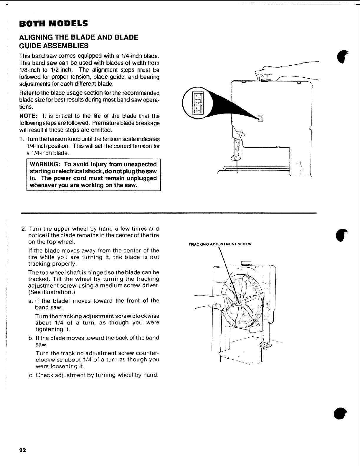
2. Turn the upper wheel by hand a few times and
notice if the blade remains in the center of the ti re
on the top wheel.
If the blade moves away from the center of the
tire while you are turning it, the blade is not
tracking properly.
The top wheel shaft is hinged so the blade can be
tracked. Tilt the wheel by turning the tracking
adjustment screw using a medium screw driver.
(See illustration.)
a. If the bladel moves toward the front of the
band saw:
Turn thetracking adjustment screw clockwise
about 1/4 of a turn, as though you were
tightening it.
b. If the blade moves toward the back of the band
saw:
C.
Turn the tracking adjustment screw counter-
clockwise about !/4 of a turn as though you
were loosening it.
Check adjustment by turning wheel by hand.
TRACKING ADJUSTMENT SCREW
• f i
r-'--- "
€
0
22
Q
O
O
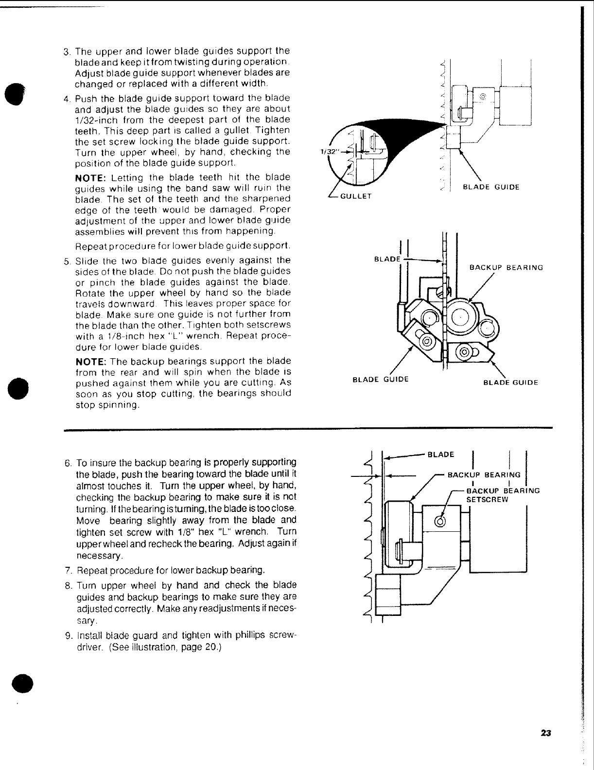
3. The upper and lower blade guides support the
blade and keep it from twisting during operation
Adjust blade guide support whenever blades are
changed or replaced with a different width.
4. Push the blade guide support toward the blade
and adjust the blade guides so they are about
1/32÷inch from the deepest part of the blade
teeth. This deep part is called a gullet Tighten
the set screw locking the blade guide support.
Turn the upper wheel, by hand, checking the
position of the blade guide support.
NOTE: Letting the blade teeth hit the blade
guides while using the band saw will ruin the
blade The set of the teeth and the sharpened
edge of the teeth would be damaged. Proper
adjustment of the upper and lower blade guide
assemblies will prevent this from happening.
Repeat procedure for lower blade guide support.
5. Slide the two blade guides evenly against the
sides of the blade. Do not push the blade guides
or pinch the blade guides against the blade.
Rotate the upper wheel by hand so the blade
travels downward This leaves proper space for
blade. Make sure one guide is not further from
the blade than the other. Tighten both setscrews
with a 1/8-inch hex "L" wrench. Repeat proce
dure for lower blade guides.
NOTE: The backup bearings support the blade
from the rear and will spin when the blade is
pushed against them while you are cutting. As
soon as you stop cutting, the bearings should
stop spinning.
GULLET
BLADEGUIDE
BLA
BEARING
BLADE GUIDE BLADE GUIDE
6. To insure the backup bearing is properly supporting
the blade, push the bearing toward the blade until it
almost touches it. Turn the upper wheel, by hand,
checking the backup bearing to make sure it is not
turning. If the bearing is turning, the blade is too close.
Move bearing slightly away from the blade and
tighten set screw with 1t8" hex %" wrench. Turn
upperwheel and recheckthe bearing. Adjust again if
necessary.
7. Repeat procedure for lower backup bearing.
8. Turn upper wheel by hand and check the blade
guides and backup bearings to make sure they are
adjusted correctly. Make any readjustments if neces-
sary.
9. install blade guard and tighten with phillips screw-
driver. (See illustration, page 20.)
/
L
i
L
L
L
i
4"--'--"--'_ B LAD E I(
•.<--.----p BACKyP BEARIING I
./ /.--"-- BACKUP BEARING
,---/-,i E'scR w
23
BOTH MODELS
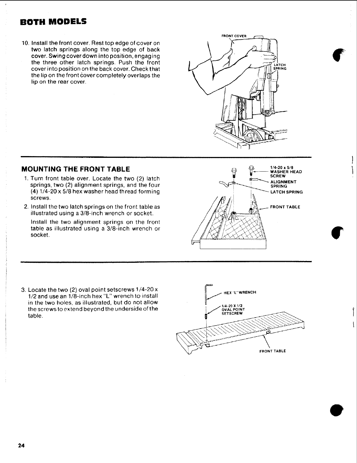
10. Install the front cover. Rest top edge of cover on
two latch springs along the top edge of back
cover. Swing cover down into position, engaging
the three other latch springs. Push the front
cover into position on the back cover. Check that
the lip on the front cover completely overlaps the
lip on the rear cover.
SPRING
€
MOUNTING THE FRONT TABLE
1. Turn front table over. Locate the two (2) latch
springs, two (2) alignment springs, and the four
(4) 1/4-20 x 5/8 hex washer head thread forming
screws.
2. Install the two latch springs on the front table as
illustrated using a 3/8-inch wrench or socket.
Install the two alignment springs on the front
table as illustrated using a 3/8-inch wrench or
socket. €
J
3. Locate the two (2) oval point setscrews 1/4-20 x
1/2 and use an 1/8-inch hex "L" wrench to install
in the two holes, as illustrated, but do not allow
the screws to extend beyond the u ncllersicle of the
table.
FRONTTABLE
e
24
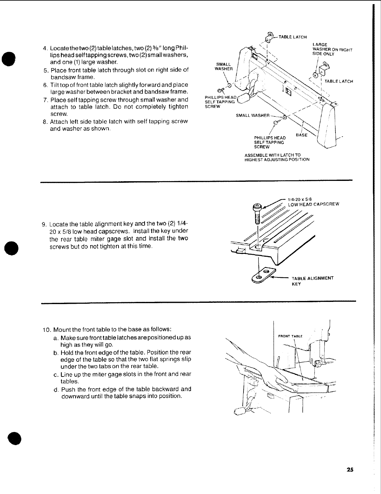
O4. Locate the two (2)table latches, two (2)3/8"long Phil-
lips head self tapping screws, two (2)small washers,
and one (1) large washer.
5. Place front table latch through slot on right side of
handsaw frame.
6. Tilt top of front table latch slightly forward and place
large washer between bracket and handsaw frame.
7. Place self tapping screw through small washer and
attach to table latch. Do not completely tighten
screw.
8. Attach left side table latch with self tapping screw
and washer as shown.
SMALL
WASHER
PHILLIPS HEAC
SELF TAPPING
SCREW
_l_-_ TABLE LATCH
,LARGE
WASHER ON RIGHT
"\ ix SIDE ONLY
\. /
\ ! TABLE LATCH
SMALL WASHER-_..._,"_ j"
7BASE
PHILLIPS HEAD
SELF TAPPING
SCREW
ASSEMBLE WITH LATCH TO
HIGHEST ADJUSTING POSITION
0
9. Locate the table alignment key and the two (2) 1/4-
20 x 5/8 low head capscrews. Installthe key under
the rear table miter gage slot and install the two
screws but do not tighten at this time.
_CAPSCREW
AL, ..E.T
10. Mount the front table to the base as follows:
a. Make sure front table latches are positioned up as
high as they will go.
b. Hold the front edge of the table. Position the rear
edge of the table so that the two flat springs slip
under the two tabs on the rear table.
c. Line up the miter gage slots in the front and rear
tables.
d. Push the front edge of the table backward and
downward until the table snaps into position.
FRONT TABLE
\
Q
25
BOTH MODELS
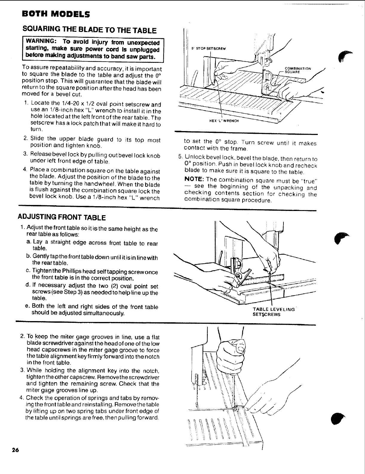
SQUARING THE BLADE TO THE TABLE
IWARNING: To avoid injury from unexpected
starting, make sure power cord Is unplugged
before making adjustments to band saw parts.
To assure repeatability.and accuracy, it is important
to square the blade to the table and adjust the 0°
position stop. This will guarantee that the blade will
return to the square position after the head has been
moved for a bevel cut,
1. Locate the 1/4-20 x 1/2 oval point setscrew and
use an !/8-inch hex "L" wrench to install it in the
hole located at the left front of the rear table. The
setscrew has a lock patch that will make it hard to
turn.
2. Slide the upper blade guard to its top most
position and tighten knob,
3. Releasebevel lock by pulling out bevel lock knob
under left front edge of table.
4, Place a combination square on the table against
the blade. Adjust the position of the blade to the
table by turning the handwheel. When the blade
is flush against the combination square lock the
bevel lock knob, Use a 1/8-inch hex "L" wrench
]
HEX "L" WRENCH
COMBINATION
SOLJARE
to set the 0° stop. Turn screw untir it makes
contact with the frame.
5. Unlock bevel lock, bevel the blade, then return to
0 ° position. Push in bevel lock knob and recheck
blade to make sure it is square to the table•
NOTE: The combination square must be "true"
-- see the beginning of the unpacking and
checking contents section for checking the
combination square procedure.
ADJUSTING FRONT TABLE
1. Adjust the front table so it is the same height as the
rear table as follows:
a, Lay a straight edge across front table to rear
table.
b. Gently tap the front table down until it is in line with
the rear table.
c. Tighten the Phillips head self tapping screw once
the front table is in the correct position.
d. If necessary adjust the two (2) oval point set
screws (see Step 3) as needed to help line up the
table.
e. Both the left and right sides of the front table
should be adjusted simultaneously.
"FABLE LEVELING
SET,_C R EWS
•
26
2. To keep the miter gage grooves in line, use a flat
blade screwdriver against the head of one of the low
head capsorews in the miter gage groove to force
the table alignment key firmly forward into the notch
in the front table.
3. While holding the alignment key into the notch,
tighten the other capscrew. Removethescrewdriver
and tighten the remaining screw. Check that the
miter gage grooves line up.
4. Check the operation of springs and tabs by remov-
ing the front table and reinstalling. Removethe table
by lifting up on two spring tabs under front edge of
the table until springs are free, then pulling forward.
e
BOTH MODELS
location and function of controls
1
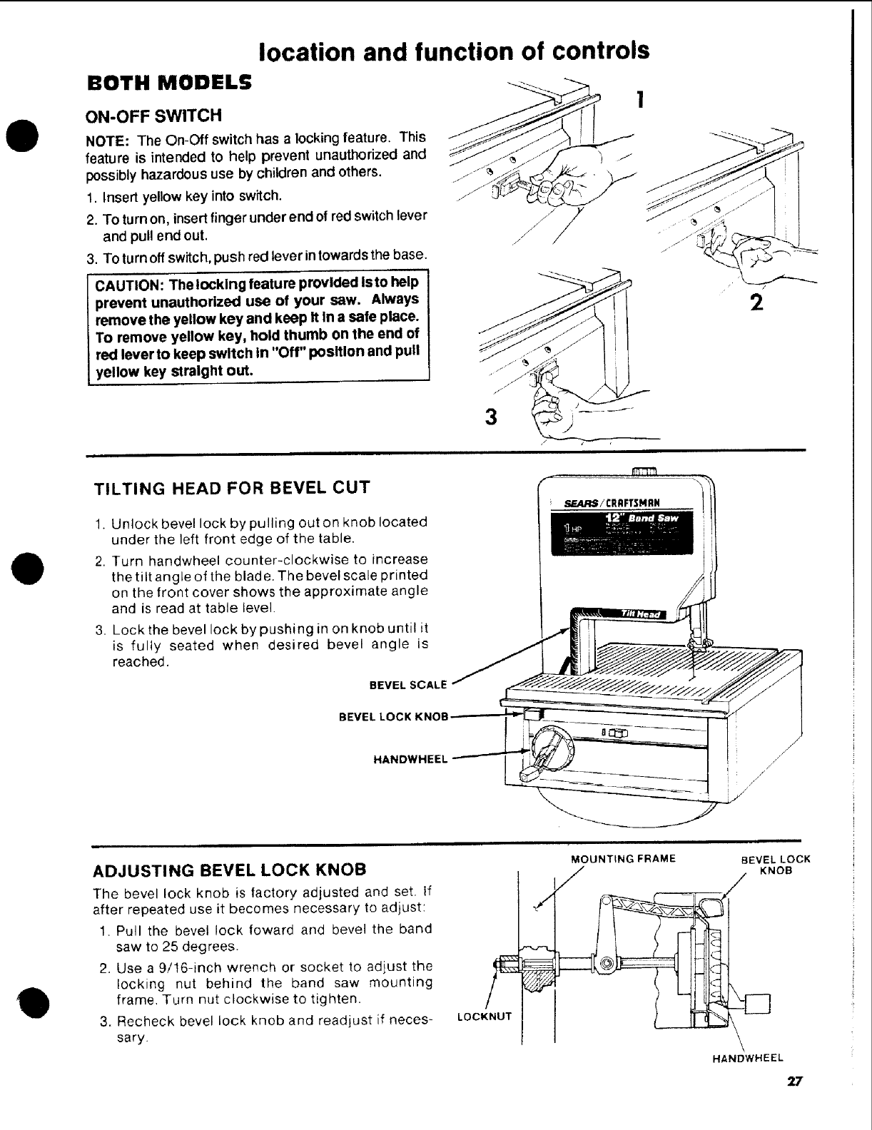
ON-OFF SWITCH
NOTE: The On-Off switch has alocking feature. This
feature is intended to help prevent unauthorized and
possibly hazardous use by children and others.
1. Insert yellow key into switch.
2. To turn on, insert finger under end of red switch lever
and pull end out.
3. To turn off switch, push red lever intowards the base.
CAUTION: The locking feature provided is to help
prevent unauthorized use of your saw. Always
remove the yellow key and keep It In a safe place.
To remove yellow key, hold thumb on the end of
red lever to keep switch In "Off" position and pull
yellow key straight out.
3
2
e
TILTING HEAD FOR BEVEL CUT
1. Unlock bevel lock by pulling out on knob located
under the left front edge of the table.
2. Turn handwheel counter-clockwise to increase
the tilt angle of the blade. The bevel scale printed
on the front cover shows the approximate angle
and is read at table level.
3. Lock the bevel lock by pushing in on knob until it
is fully seated when desired bevel angle is
reached.
BEVEL SCALE
BEVEL LOCK KNOB
HANDWHEEL
i,_J_rS /CRAFTSMRN
\
Q
ADJUSTING BEVEL LOCK KNOB
The bevel lock knob is factory adjusted and set. If
after repeated use it becomes necessary to adjust:
1. Pull the bevel lock foward and bevel the band
saw to 25 degrees.
2. Use a 9/16-inch wrench or socket to adjust the
locking nut behind the band saw mounting
frame, Turn nut clockwise to tighten.
3. Recheck bevel lock knob and readjust if neces-
sary.
9
LOCKNUT
,/
MOUNTING FRAME
/BEVEL LOCK
KNOB
HANDWHEEL
27

basic band saw operation
BEFORE USING THE SAW:
WARNING: TO avoid mistakes that could cause I
serious, permanent Injury, do not plug the saw in
until the following steps are completed.
•Assembly and alignment (See pages 11 - 18.)
• Learn the use and function of the ON-OFF switch,
bevel handwheel, bevel lock knob, blade guides,
backup bearing, guide bar lock knob, and blade
guard. (See page 19.)
•Review and understanding of all safety instructions
and operating procedures in this manual.
• Review of the maintenance methods for this saw.
(See page 36.)
To avoid back injury, get help or use recommended
casterswhe nyou needto more the saw. Always get help
if you need to lift the saw.
NEVER STAND ON TOOL. Serious injury could occur
if the tool tips or you accidentally hit the cutting tool. Do
not store anything above or near the tool where anyone
might stand on the tool to reach them.
BEFORE EACH USE:
Inspect your saw.
DISCONN ECT THE SAW. Toavoid injuryfrom acciden-
tal starting, unplug the saw, turn the switch off and
remove lhe switch key before changing the setup,
removing covers, guards, blade or sanding belt.
CHECK DAMAGED PARTS. Check for:
• alignment of moving parts,
•binding of moving parts,
• broken parts,
• stable mounting, and
• any other conditions that may affect the way the saw
works
If any part is missing, bent, or broken in any way, or any
electrical parts don't work properly, turn the saw off and
unplug the saw. RE PLACE damaged, missing, or failed
parts before using the saw again.
MAINTAIN TOOLS WITH CARE. Keep the saw clean
for best and safest performance. Follow instructions for
lubricating.
REMOVE ADJUSTING KEYS AND WRENCHES from
tool before turning it on.
To avoid injury from jams, slips or thrown pieces or
broken blades:
Use of right blade size, style and cutting speed for the
material and the type of cutting you plan to do.
USE ONLYRECOMMENDED ACCESSORIES. (See
page 36) Consult this Owner's manual for recom-
mended accessories. Follow the instructions that
come with the accessories. The use improper acces-
sories may cause risk of injury to persons.
•Make sure the blade teeth point downward, toward
the table.
Make sure the blade guides and thrust bearings are
properly adjusted.
Make sure the blade or sanding belt tension is prop-
erly adjusted.
Before sanding, adjust the sanding platen to clear the
table by no more than 1/8 of an inch.
Make sure the bevel clamp is tight and no parts have
excessive play.
To avoid accidental blade contact, minimize blade
breakage and provide maximum blade support, al-
ways adjust the upper blade guide and blade guard to
just clear the workpiece.
•KEEP 'WORK AREA CLEAN. Cluttered areas and
benches invite accidents. Floor must not be slippery.
To avoid burns or otherfire damage, never use the saw
near flammable liquids, vapors or gases.
Plan ahead to protect your eyes, hands,
face and ears.
KNOW YOUR SAW. Read an understand the owner's
manual and labels affixed to the tool. Learn its applica-
tion and limitations as well as the specific potential
hazards peculiar to this tool.
f
26
O
II
To avoid injury from accidental contact with moving
parts, don't do layout, assembly, or setup work on the
saw while any parts are moving.
AVOID ACCIDENTAL STARTING. Make sure switch is
"OFF" before plugging saw into a power outlet.
Plan your work.
• USE THE RIGHT TOOL. Don't force tool or attach-
ment to do a job it was not designed to do.
Use model 113.248211 to cut and sand only wood,
wood like products, and plastics.
CAUTION: To avoid blade breakage, fire or
other damage to the saw, NEVER use model
113.248211 to cut metals.
• Use model 113.248321 to cut and sand only wood,
wood like products, plastics and non-ferrous metals.
CAUTION: Model 113.248321 is NOT designed
for cutting or sanding ferrous metals like iron
or steel. When cutting or sanding non-ferrous
metals (brass, copper and aluminum, etc.),
metal shavings can react with wood dust and
start a tire. To avoid this:
Discon nect any type of dust collecting hose
from the saw.
• Remove all traces of wood dust from Inside
the saw.
Remove all metal shavings from inside the
saw before sawing wood, again.
Dress for safety.
Any power saw can throw foreign objects into the eyes.
This can cause permanent eye damage. Wear safety
goggles (not glasses) that comply with ANSI Z87.1
(shown on package). Everyday eyeglasses have only
impact resistant lenses. They are not safety glasses.
Safety goggles are available at Sears retail catalog
stores. Glasses or goggles not in compliance with ANSI
Z87.1 could seriously hurt you when they break.
•Do not wear loose clothing, gloves, neckties or jew-
elry (rings, wrist watches). They can get caught and
draw you into moving parts.
• Wear nonslip footwear.
• Tie back long hair.
• Roll long sleeves above the elbow.
•Noise levels vary widely. To avoid possible hearing
damage, wear ear plugs or muffs when using saw for
hours at a time.
•Fordusty operations, wear adust mask alongwith the
safety goggles.
Inspect your workpiece.
Make sure there are no nails or foreign objects inthe part
of the workpiece to be cut.
Use extra caution with large, very small or awkward
workpieces:
- Use extra supports (tables, saw horses, blocks,
etc.) for any workpieces large enough to tip when
not held down to the table top.
NEVER use another person as a substitute for a
table extension, or as additional support for a
workpiece that is longer or wider than the basic
saw table, or to help feed, support or pull the
workpiece.
When cutting irregularly shaped workpieces, plan
your work so it will not pinch the blade. A piece of
molding, for example, must lay flat or be held by a
fixture o rjig that will not let it twist, rock or slip while
being cut.
Properly support round material such as dowel
rods, or tubing. They have a tendencyto roll during
a cut, causing the blade to "bite". To avoid this,
always use a '_/" block or clamp the work to the
miter gage.
•Cut only one workpiece at a time.
•Clear everything exceptthe workpiece and related
support devices off the table before turning the saw
on.
Plan the way you will hold the workpiece from start
to finish.
Do not hand hold pieces so small that your fingers will
go under the blade guard. Use jigs or fixtures to hold
the work and keep your hands away from the blade.
SECURE WORK. Use clamps to hold work when
practical. It's often safer than using your hand, and
frees both hands to operate the tool.
29
Avoidawkward operations and hand positions where
asudden slipcould cause fingers orhandto move into
the blade or sanding surface.
DONq" OVERREACH. Keep good tooting and bal-
ance.
WHENEVER SAW IS RUNNING.
WARNING: Don't let familiarity (gained from fre-
quent use of your band saw) cause a careless
mistake. A careless fraction of a second isenough
to cause a severe Injury.
Before starting your cut, watch the saw while it runs. It
it makes an unfamiliar noise or vibrates a lot, stop
immediately. Turn the saw off. Unplug the saw. Do not
restart until finding and correcting the problem.
KEEP CHILDREN AWAY. Keep all visitors a safe
distancefrom the saw. Make sure bystanders are clear
of the saw and workpiece.
DON'T FORCE TOOL It will do the job betler and safer
at its designed rate. Feed the workpiece into the saw
blade only fast enough to let it cut withoutbogging down
or binding.
Before freeing any jammed material:
•Turn switch "OFF".
• Remove switch key.
•Unplug the saw.
•Wait for all moving parts to stop.
When backing up theworkpiece, the blade may bind
In the kerr (cut). This Is usually caused by sawdust
clogging up the ke rf or because the blade comes out
of the guides. If this happens:
• Turn switch "OFF".
•Remove switch key.
• Unplug saw.
•Wait for all moving parts to siop.
• Remove band saw cover.
•Stick flat blade screwdriver or wedge into the kerf.
• "rum the upper wheel by hand while backing up the
workpiece.
Before removing loose pieces from the table, turn saw
off and wait for all moving parts to stop.
BEFORE LEAVING THE SAW:
Wait for all moving parts to stop.
Makeworkshopchild-proof. Lockthe shop. Disconnecl
master switches. Remove the yellow switch key. Store
it away from children and others not qualified to use the
tool.
30
OI
CAUTION: For your safety, comply with all the I
safety instructions on pages 2- 5 before using the I
band saw.
A band saw is basically a "curve cutting" machine. It
is not capable of doing inside cutting.
Your Craftsman Band Saw is not only capable of the
usual band saw operations, but it can be converted
into a sander as well. You can finish wood, certain
compositions and plastics.
It is also used for straight-line cutting operations
such as crosscutting, ripping, mitering, beveling,
compound cutting, and resawing.
Operation Recommended Blade Size
(Inches)
Cross Cutting 1/4, 3/8, 1/2
Ripping 1/2
Mitering 1/4, 3/8, 1/2
Beveling 1/4, 3/8, 1/2
Compound Cutting 1/4, 3/8, 1/2
Circle Cutting See Chart Below
Resawing 1/2
Curve Cutting 1/8, 1/4
Extremely Fine Scroll
Cutting (Thin Material Only) 1/16
O
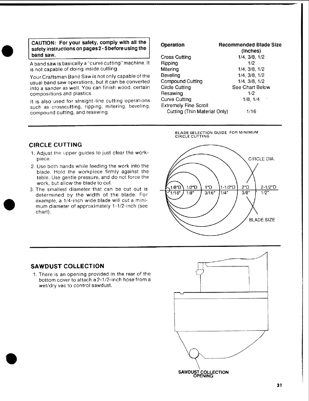
CIRCLE CUTTING
1. Adjust the upper guides to just clear the work-
piece.
2. Use both hands while feeding the work into the
blade. Hold the workpiece firmly against the
table. Use gentle pressure, and do not force the
work, but allow the blade to cut.
3. The smallest diameter that can be cut out is
determined by the width of the blade. For
example, a 1/4-inch wide blade will cut a mini-
mum diameter of approximately 1-1/2-inch (see
chart).
BLADE SELECTION GUIDE FOR MINIMUM
CIRCLE CUTTING
CIRCI LE DIA.
2-1/2"D
3/_i/4"/ 3/_ 1/2"
_ BLADE SIZE
SAWDUST COLLECTION
1. There is an opening provided in the rear of the
bottom cover to attach a 2-1/2-inch hose from a
wet/dry vac to control sawdust.
Q
SAWDUST COLLECTION
OPENING
31
BOTH MODELS
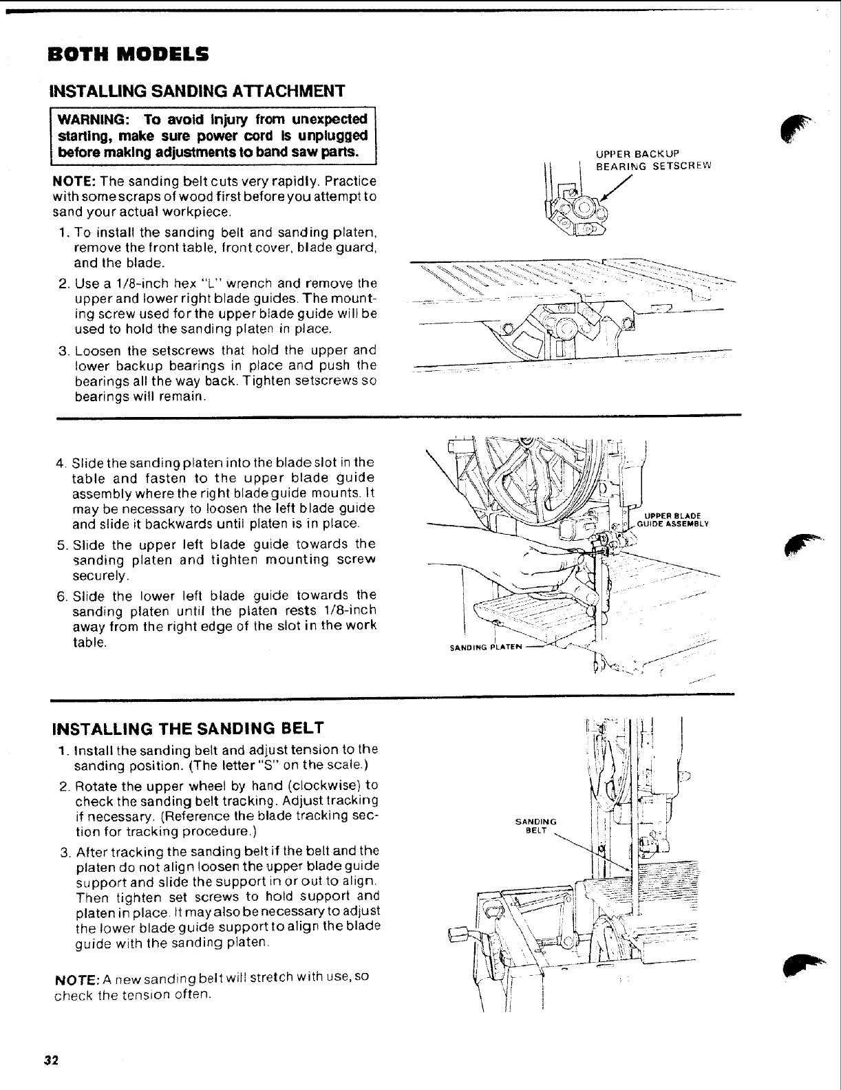
INSTALLING SANDING ATTACHMENT
IWARNING: To avoid Injury from unexpected
starting, make sure power cord Is unplugged
before making adjustments to band saw parts.
NOTE: The sanding belt cuts very rapidly. Practice
with some scraps of wood first before you attempt to
sand your actual workpiece.
1. To install the sanding belt and sanding platen,
remove the front table, front cover, blade guard,
and the blade.
2. Use a 1/8-inch hex "L" wrench and remove the
upper and lower right blade guides. The mount-
ing screw used for the upper blade guide will be
used to hold the sanding platen in place.
3. Loosen the setscrews that hold the upper and
lower backup bearings in place and push the
bearings all the way back. Tighten setscrews so
bearings will remain.
UPPER BACKUP
II 1 SEARING SETSCREW
4. Slide the sanding platen into the blade slot in the
table and fasten to the upper blade guide
assembly where the rig hi blade guide mounts. It
may be necessary to loosen the left blade guide
and slide it backwards until platen is in place.
5. Slide the upper left blade guide towards the
sanding platen and tighten mounting screw
securely.
6. Slide the lower left blade guide towards the
sanding platen until the platen rests 1/8-inch
away from the right edge of the slot in the work
table, J
SANDING PLATE
INSTALLING THE SANDING BELT
1. Install the sanding belt and adjust tension to the
sanding position. (The letter "S" on the scale.)
2. Rotate the upper wheel by hand (clockwise) to
check the sanding belt tracking. Adjust tracking
if necessary. (Reference the blade tracking sec-
tion for tracking procedure.)
3. After tracking the sanding belt if the belt and the
platen do not align loosen the upper blade guide
support and slide the support in or out to align.
Then tighten set screws to hold support and
platen in place. It may also be necessary to adjust
the lower blade guide support to align the blade
guide with the sanding platen.
NOTE: A new sanding belt will stretch with use, so
check the tension often.
j_f •
'. ,
li ]
32
P
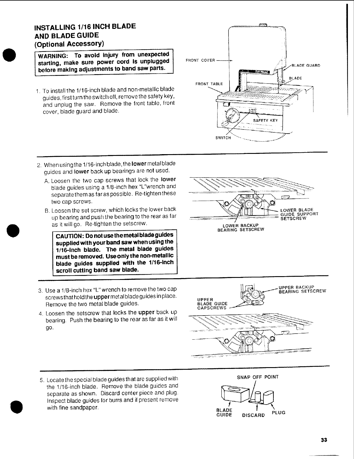
INSTALLING 1/16 INCH BLADE
AND BLADE GUIDE
(Optional Accessory)
WARNING: TO avoid injury from unexpected
starting, make sure power cord Is unplugged
betore making adjustments to band saw pans. I
1. To install the 1/16-inch blade and non-metallic blade
guides, first turn the switch ell, remove the safety key,
and unplug the saw. Remove the front table, front
cover, blade guard and blade,
FRONT COVER _
-BLADE GUARD
BLADE
FRONT TABLE ,_: __._
SWITCH "- _
D
2. When using the 1/16-inch blade, the lower metal blade
guides and lower back up bearings are not used.
A. Loosen the two cap screws that lock the lower
blade guides using a ltS-inch hex "L"wrench and
separate them as far as possible. Re-tighten these
two cap screws.
B. Loosen the set screw, which locks the lower back
up bearing and push the bearing to the rear as far
as it will go. Re-tighten the setscrew•
CAUTION: Do not use the metal blade guides
supplied with your band saw when using the
1/16-Inch blade. The metal blade guides
must be removed. Useonlythe non-metallic
blade guides supplied with the 1/16-inch
scroll cutting band saw blade.
,OWERB ADE
x-.'."_ll,I =._IFI i I GUIDE SUPPORT
7 SETSCREW
LOWER BACKUP
BEARING SETSCREW
3. Use a 1/8-inch hex "L"wrench to remove the two cap
screwsthat holdthe upper metal blade guides inplace.
Remove the two metal blade guides,
4. Loosen the setscrew that locks the upper back up
bearing. Push the bearing to the rear as far as it wi!l
go.
|
5. Locate the special blade guides that are supplied with
the 1/16-inch blade. Remove the blade guides and
separate as shown. Discard center piece and plug.
Inspect blade guides lor burrs and if present remove
with fine sandpaper.
SNAP OFF POINT
BLADE
GUIDE DISCARD PLUG
33
BOTH MODELS
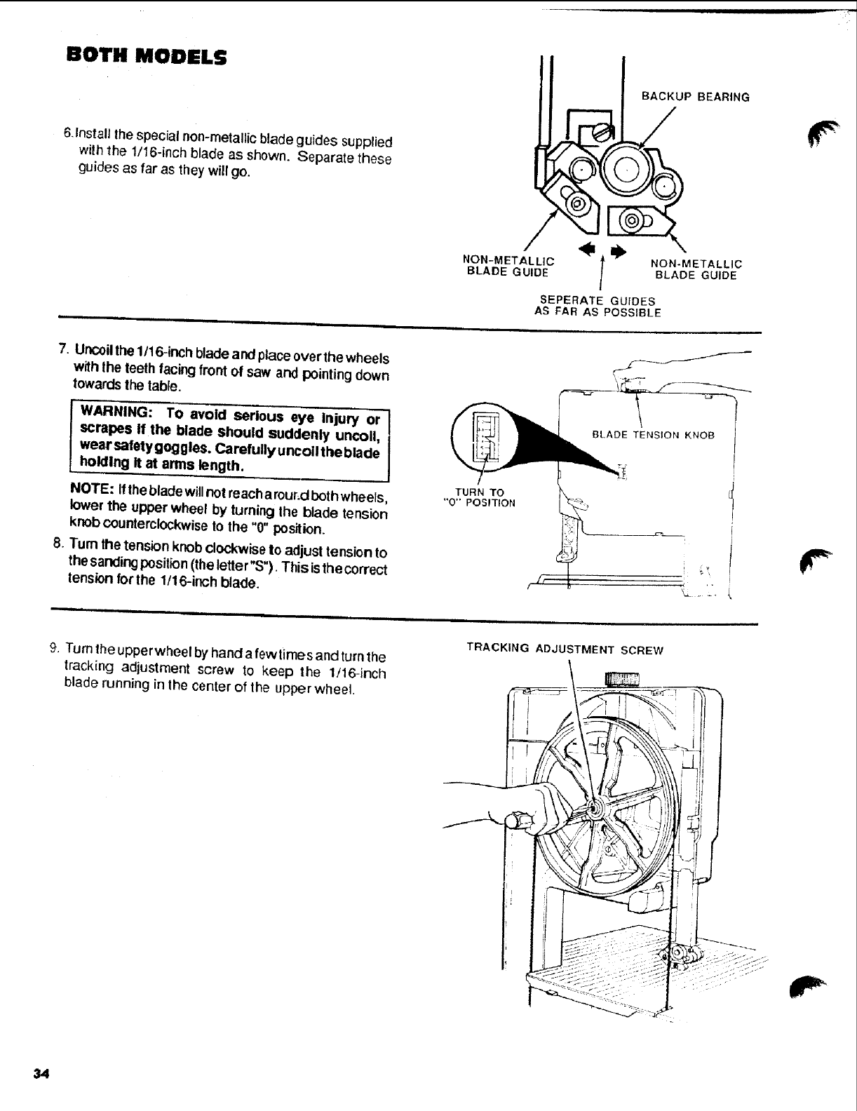
6.Install the special non-metallic blade guides supplied
with the 1/16-inch blade as sho_n. Separate these
guides as far as they will go.
BACKUP BEARING
SEPERATE GUIDES
AS FAR AS POSSIBLE
7. Uncoilthe 1/16-inch blade and place over the wheels
with lhe teeth facing front of saw and pointing down
towards the lable.
WARNING: TO avoid serious eye Injury or
scrapes, the blade should suddenly uncoil,
wear safety goggles. Carefully uncoil the blade
homing It at arms length.
NOTE: It thebladewill not reachamur,d bethwheets,
lower the upper wheel by turning the blade tension
knob counterclockwise to the "0" position.
8. Turn the tension knob clockwise to adjust tension to
the sanding position(the letter"S"). This isthe correct
tension for the 1/16-inoh blade.
TURN TO
"0" POSITION
+ i
9. Turn 1heupperwheel by hand afewlirnes and turnthe
tracking adjustment screw to keep the 1/16-inch
blade running in lhe center of the upper wheel.
TRACKING ADJUSTMENT SCREW
r
34
O
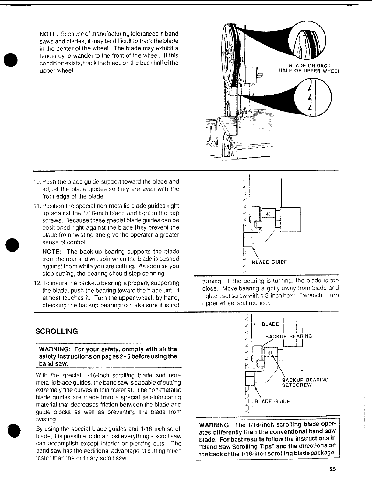
NOTE: Because of manufacturing tolerances in band
saws and blades, it may be difficult to track the blade
in the center of the wheel. The blade may exhibit a
tendency to wander to the front of the wheel. It this
condition exists,trackthe bladeonthe back half of the
upper wheel. BLADE ON BACK
HALF OF UPPER WHEEL
O
O
10. Push the blade guide support toward the blade and
adjust the blade guides so they are even with the
front edge of the blade.
1!. Position the special non-metallic blade guides right
up against the 1/16-inch blade and tighten the cap
screws. Because these special blade guides can be
positioned right against the blade they prevent the
blade from twisting and give the operator a greater
sense of control.
NOTE: The back-up bearing supports the blade
from the rear and will spin when the blade is pushed
against them while you are cutting. As soon as you
stop cutting, the bearing should stop spinning.
12. To insure the back-up bearing is properly supporting
the blade, push the bearing toward the blade until it
almost touches it. Turn the upper wheel, by hand,
checking the backup bearing to make sure it is not
SCROLLING
I
WARNING: For your safety, comply with all the I
safety instructions on peges 2- 5before using the Iband saw.
With the special 1/16-inch scrolling blade and non-
metallic blade guides, the band saw is capable of cutting
extremely fine curves in thin material. The non-metallic
blade guides are made from a special self-lubricating
material that decreases friction between the blade and
guide blocks as well as preventing the blade from
twisting.
By using the special blade guides and 1/16-inch scroll
BLADE GUIDE
turning. I1the bearing is turning, the blade is too
close. Move bearing slightly away from blade and
tighten set screw with 1/8-inch hex "L" wrenctl. Turn
upper wheel and recheck
blade, it is possible to do almost everything a scroll saw
can accomplish except interior or piercing cuts. The
band saw has the additional advantage of cutting much
faster than the ordinary scroll saw.
BLADE GUIDE
WARNING: The 1/16-inch scrolling blade oper-
ates differently than the conventional band saw
blade. For best results follow the instructions in
"Band Saw Scrolling Tips" and the directions on
the back of the 1/16-inch scrolling blade package.
35
BOTH MODELS
Sears recommends the following Accessories
Caster Set for Leg Set ..................... 9-22222, 9-22221
Miter Gauge .................................................... 9-29929
Hold-Down Clamp for Miter Gauge ................. 9 29928
Stop-Rods for Miter Gauge ............................. 9-29924
Rip Fence ........................................................ 9-23402
Blades and Sanding Belts ........................ See Catalog
Circle Cutting Attachment ............................... 9-23411
Power Tool Know How Handbook .................. 9-29117
Sears may recommend other accessories not listed in
the manual. See your nearest Sears store or Catalog
department for other accessories.
Do not use any accessory unless you have received and
read complete instructions for its use.
#-
maintenance
BOTH MODELS
I WARNING: Foryourown safety, turn switch"Off"
and remove plug from power source outlet before
maintaining or lubricating your band saw.
Tires
Pitch and sawdust that build up on the tires should be
removed with a stiffbrush or scraped off with a piece of
wood.
NOTICE: To avold damaging the tires do not use a
sharp knife or any kind or solvent.
When the tires become worn they should be replaced,
When replacing thetires, stretchthem amundthewheels
but do not glue them on.
ADJUSTING BAND SAW BEVEL TRAVEL
If the band saw will not hold its position when at a
bevel angle, and before the bevel lock is locked, or if
it is difficult to change the bevel angle, an adjustment
is necessary to correct the force required to bevel
the band saw.
To adjust the force required to bevel the band saw,
locate the three (3) eapscrews holding the frame to
the motor mount. The capscrews are located in the
recessed area behind the hub of the lower wheel at
the 2o'c lock, 6 o'clock, and 10 o'clock positions. Use
a 3/16-inch hexagonal "L" wrench that has a 4-inch
leg, reach between the spokes of the lower wheel to
the capscrews. Adjust the capscrews equally until
the bevel action is smooth and the saw will held its
position before tt_e beret lock is locked.
ADJUSTING THE UPPER BLADE GUIDE
TRAVEL
If the upper guide bar will not move up and down
easily or falls when the lock knob is loosened, the
following adjustment should be performed
I. Remove the Guide Bar Lock Knob and the
washer which is under it
2. Using a 7/16" socket or wrench tigiqten the nut
which is under the washer to just tight
3, Then loosen the same nut 1 turn
4. Move the guide bar up and down to check for
smooth movement while still holding its position
when released.
5 Make further adjustments to the nut as required
to get the guide bar to move smoothly and hold
its position when released.
6. Reinstall the washer and Guide Bar Lock Knob.
General Maintenance
Keep your band saw clean. Remove the sawdust from
the inside. Vacuum or blow out frequently.
Do not allow filth to build up on the table the guides or
the back-up bearings. Clean them with Craftsman
Gum and Pitch Remover.
NOTICE: Do not Immerse the back-up bearings In
the gum and pitch remover.
Put athin coat of paste wax on the table so that the wood
slides easily while cutting.
#.-
36
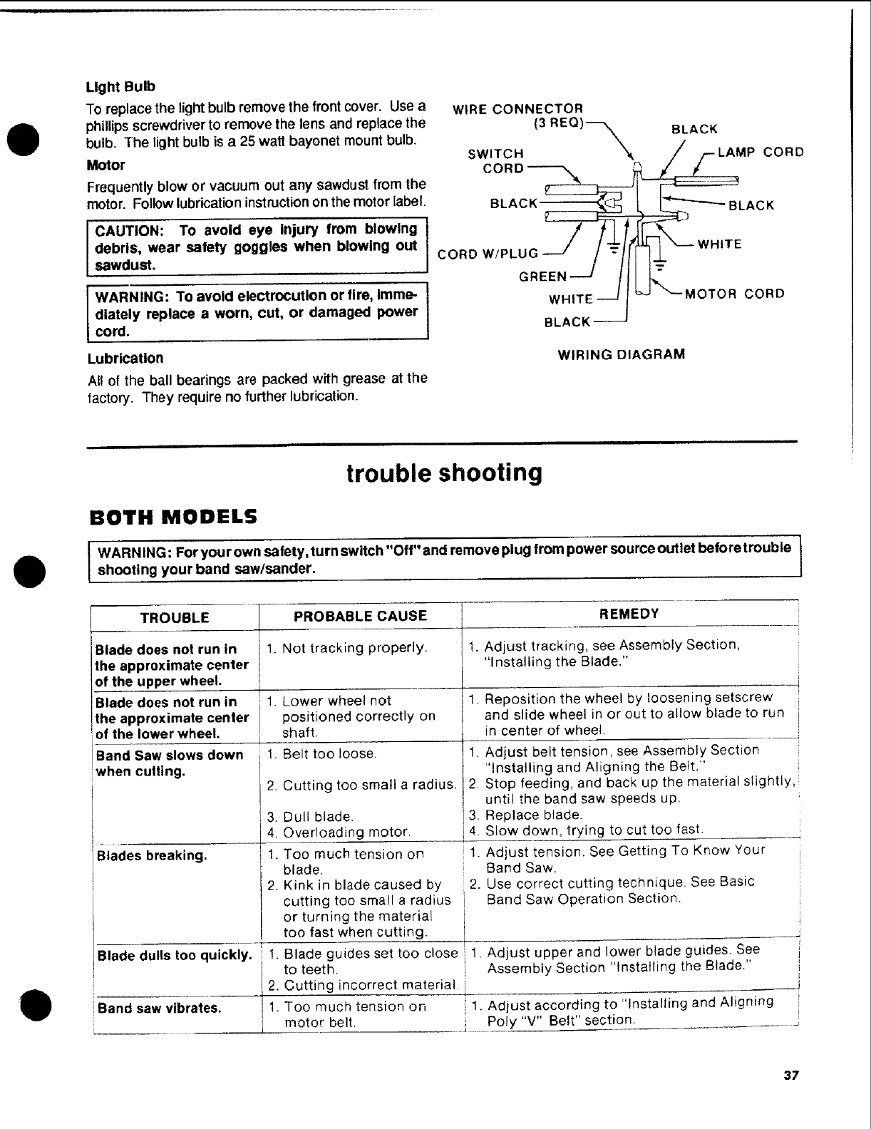
O
Light Bulb
To replace the light bulb remove the front cover. Use a
phillips screwdriver to remove the lens and replace the
bulb. The light bulb is a 25 watt bayonet mount bulb.
Motor CORD
Frequently blow or vacuum out any sawdust from the
motor. Follow lubrication instruction on the motor label. BLACK_
ICORD W/PLUG--J /-z
GREEN ---_
CAUTION: To avoid eye Injury from blowing
debris, wear safety goggles when blowing out
sawdust.
WARNING: To avoid electrocution or fire, imme- I
diately replace a worn, cut, or damaged power I
cord.
WIRE CONNECTOR
SWITCH (3 REQ) X---X BLACK P CORD
'---BLACK
WHITE
MOTOR CORD
Lubrication
All of the ball bearings are packed with grease at the
factory. They require no further lubrication.
WHITE _
BLACK --
WIRING DIAGRAM
O
Q
trouble shooting
BOTH MODELS
IWARN ING: For your own safety,turn switch "Off" and remove plug from power source outlet before trouble
shooting your band saw/sander.
TROUBLE
Blade does not run in
the approximate center
of the upper wheel.
Blade does not run in
the approximate center
of the lower wheel.
Band Saw slows down
when cutting.
Blades breaking.
PROBABLE CAUSE
1. Not tracking properly.
1.
,
Lower wheel not 1.
positioned correctly on
shaft.
Belt too loose. 1,
2. Cutting too small a radius. 2.
.
4.
1.
2.
Dull blade. 3,
Overloading motor, '4.
Too much tension on 1.
blade.
Kink in blade caused by 2.
cutting too small a radius
or turning the material
too fast when cutting.
Blade guides set too close 1
to teeth.
incorrect material, iCutting
Too much tension on ! 1
motor belt.
REMEDY
Adjust tracking, see Assembly Section,
"Installing the Blade."
I
]
Reposition the wheel by loosening setscrew
and slide wheel in or out to allow blade to run i
in center of wheel.
Adjust belt tension, see Assembly Section
"Installing and Aligning the Belt." !
Stop feeding, and back up the material slightly,
until the band saw speeds up.
Replace blade.
Slow down, trying to cut too fast.
Adjust tension. See Getting To Know Your
Band Saw.
Use correct cutting technique. See Basic
Band Saw Operation Section.
Blade dulls too quickly. 1. ,Adjust upper and lower blade guides. See
Assembly Section "Installing the Blade."
2.
!Band saw vibrates. 1. .Adjust according to "Insta!ling and Aligning
I Poly "V" Belt" section.
37

trouble shooting--motor
BOTH MODELS
NOTE: Motors used on wood-working tools are particularly susceptible to the
accumulation of sawdust and wood chips and should be blown out or "vacuumed"
frequently to prevent interference with normal motor ventilation and proper
operation of the centrifugally-operated starting switch.
TROUBLE I
Excessive noise. 1.
Motor fails to develop
full power. NOTE:
LOW VOLTAGE: (Power
output of motor
decreases rapidly with
decrease in voltage at
motor terminals. For
example, areduction of
10% in voltage causes
a reduction of 19% in
maximum power output
of which the motor is
capable, and a reduction
of 20% in voltage causes
a reduction of 36% in
maximum power
output.)
'Motor starts slowly
or fails to come up
to full speed.
i
Motor overheats.
Starting switch in
motor will not operate.
Motor stalls
(resulting in blown
fuses or tripped
circuit breakers).
PROBABLE CAUSE
Motor.
.
Circuit overloaded with
lights, appliances and
other motors,
Undersize wires or circuit
too long.
General overloading of
power conqpany
facilities,
11 LOW voltage.
2. Windings burned out
or open,
3. Starting switch not
operating.
1. Motor overloaded.
2. mproper cooling (Air
circulation restricted
through motor due to
sawdust accumulation.
1.
.
3.
Burned switch contacts
(due to extended hold-in
periods caused by low line
voltage, etc.)
Shorted capacitor.
Loose or broken
connections,
1. Starting switch not
operating.
' 2. Voltage too _ow to permit
motor to reach operating
speed.
,3. Fuses or circuit breakers
J do not have sufficient
capacity,
Frequent opening of
! fuses or circuit
breakers.
REMEDY
1, Have motor checked by qualified service
technician, Repair service is available at your
nearest Sears store.
1. Do not use other appliances or motors on
same circuit when using the saw.
2. Increase wire sizes, or reduce length of wiring.
See "Motor Specifications and Electrical
Requirements" section.
3. Request a voltage check from the power
company.
1. Request voltage check from the power
company. Check size of circuit wiring.
2, Have motor repaired or replaced.
3. Biow out sawdust from motor. Have motor
repaired,
1. Feed work slower into blade,
2. Clean out sawdust to provide normal air
circulation through motor. See "Maintenance
and Lubrication" section.
1. Have switch replaced and request a voltage
i check from the power company.
i 2. Have capacitor tested and replace if defective.
3, Have wiring checked and repaired.
1. Have switch replaced.
2. Request voltage check from the power
company.
3, Install proper size fuses or circuit breakers
t. Motor overloaded, i I, Feed work siower into blade.
2, Fuses or circuit breakers i 2. Install proper size fuses or circuit breakers
do not have sufficient Check that wiring will handle load
capacity.
3. Starting switch not 3. Have switch replaced. Blow out sawdust.
operatir_g (motor does not
reach speed).
38
#,,.

notes
0
0
0
39
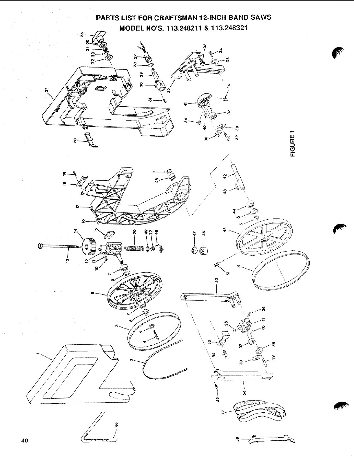
PARTS LIST FOR CRAFTSMAN 12-INCH BAND SAWS
MODEL NO'S. 113.248211 &113.248321
\
,
4O
ILl
r.t-
g
Li.
\
/"
\
u_
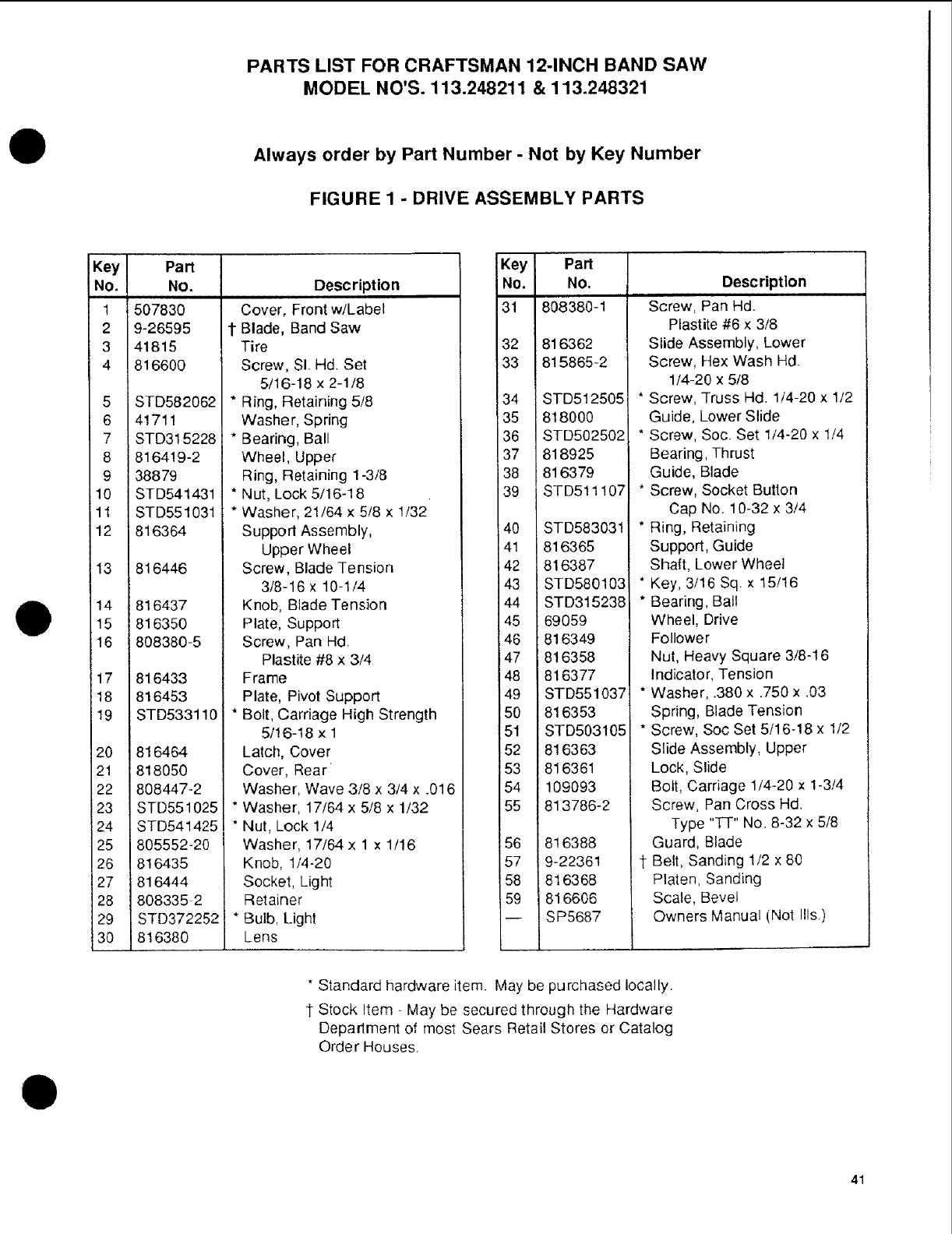
PARTS LIST FOR CRAFTSMAN 12-INCH BAND SAW
MODEL NO'S. 113.248211 & 113.248321
OAlways order by Part Number - Not by Key Number
FIGURE 1 - DRIVE ASSEMBLY PARTS
O
Key
No.
1
2
3
4
5
6
7
8
9
10
11
12
13
14
15
16
17
18
19
2O
21
22
23
24
25
26
27
28
29
3O
Part
No.
507830
9-26595
41815
816600
STD582062
41711
STD315228
8164! 9-2
38879
STD541431
STD551031
816364
816446
i816437
816350
808380-5
816433
816453
STD533119
816464
818050
808447-2
STD551025
STD541425
805552-20
816435
816444
808335 2
STD372252
816380
Description
Cover, Front w/Label
1 Blade, Band Saw
Tire
Screw, SI. Hd. Set
5/16-18 x 2-1/8
* Ring, Retaining 5/8
Washer, Spring
*Bearing, Ball
Wheel, Upper
Ring, Retaining 1-3/8
* Nut, Lock 5/16-18
* Washer, 21/64 x 5/8 x 1/32
Support Assembly,
Upper Wheel
Screw, Blade Tension
3/8-16 x 10-1/4
Knob, Blade Tension
Plate, Support
Screw, Pan Hd.
Plastite #8 x 3/4
Frame
Plate, Pivot Support
* Bolt, Carriage High Strength
5/16-18 x 1
Latch, Cover
Cover, Rear
Washer, Wave 3/8 x 3/4 x .016
* Washer, 17/64 x 5/8 x 1/32
* Nut, Lock 1/4
Washer, 17/64 x 1 x 1/16
Knob, 1/4-20
Socket, Light
Retainer
* Bulb, Light
Lens
Key Pan
No. No.
31 808380-1
32 816362
33 815865-2
34 STD512505
35 818000
36 STD502502
37 818925
38 816379
39 STD511107
40 STD583031
41 816365
42 816387
43 STD580103
44 STD315238
45 69059
146 816349
147 816358
48 816377
49 STD551037
50 816353
51 STD503105
52 816363
53 816361
54 109093
55 813786-2
56 816388
57 9-22361
58 816368
59 816606
-- SP5687
Description
Screw, Pan Hd.
Plastite #6 x 3/8
Slide Assembly, Lower
Screw, Hex Wash Hd.
1/4-20 x 5/8
* Screw, Truss Hal. 1/4-20 x 1/2
Guide, Lower Slide
* Screw, Soc. Set 1/4-20 x 1/4
Bearing, Thrust
Guide, Blade
* Screw, Socket Button
Cap No. 10-32 x 3/4
* Ring, Retaining
Support, Guide
Shaft, Lower Wheel
* Key, 3/16 Sq. x 15/16
* Bearing, Ball
Wheel, Drive
Follower
Nut, Heavy Square 3/8-16
Indicator, Tension
* Washer, .380 x .750 x .03
Spring, Blade Tension
* Screw, Soc Set 5/16-18 x 1/2
Slide Assembly, Upper
Lock, Slide
Bolt, Carriage 1/4-20 x 1-3/4
Screw, Pan Cross Hd.
Type "-f-r" No. 8-32 x 5/8
Guard, Blade
1-Belt, Sanding 1/2 x 80
Platen, Sanding
Scale, Bevel
Owners Manual (Not Ills.)
O
* Standard hardware item. May be purchased locally.
1"Stock Item - May be secured through the Hardware
Department of most Sears Retail Stores or Catalog
Order Houses.
41
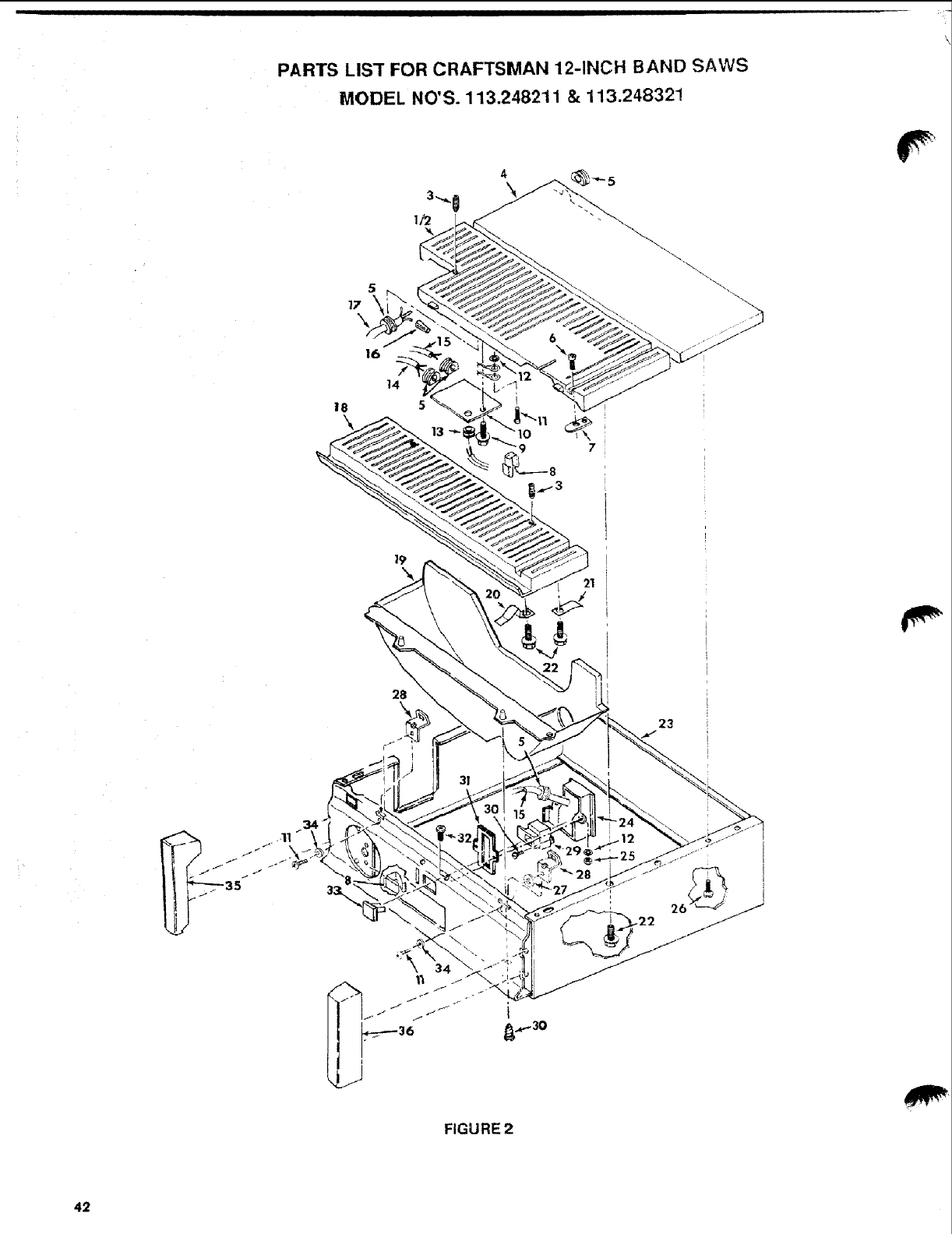
PARTS LIST FOR CRAFTSMAN 12-INCH BAND SAWS
MODEL NO'S. 113.248211 & 113.248321
5
14
18
\
97
_+"5
28
\23
35
"11
FIGURE 2
42
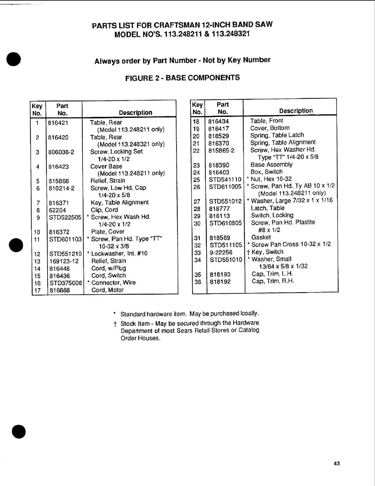
PARTS LIST FOR CRAFTSMAN 12-INCH BAND SAW
MODEL NO'S. 113.248211 & 113.248321
Always order by Part Number -Not by Key Number
FIGURE 2 -BASE COMPONENTS
Key
NO.
1
2
3
4
5
6
7
8
9
10
11
12
13
"4
Pan
No.
816421
816420
806036-2
816423
815868
810214-2
816371
62204
STD522505
816372
STD601103
STD551210
169123-12
816448
816436
STD375006
816888
Description
Table, Rear
(Model 113.248211 only)
Table, Rear
(Model 113.248321 only)
Screw, Locking Set
1/4-20 x 1/2
Cover Base
(Model 113.248211 only)
Relief, Strain
Screw, Low Hd. Cap
1/4-20 x 5/8
Key, Table Alignment
Clip, Cord
Screw, Hex Wash Hd.
1/4-20 x 1/2
Plate, Cover
Screw, Pan Hd. Type "TT"
10-32 x 3/8
Lockwasher, Int. #10
Relief, Strain
Cord, w/Plug
Cord. Switch
Connector, Wire
Cord, Motor
Key Pa_
No. No.
18 816434
19 816417
20 818529
21 816370
22 815865-2
23 818390
24 816403
25 STD541110
26 STD611005
27 STD551012
28 818777
29 816113
30 STD610805
31 818569
32 STD511105
33 9-22256
34 STD551010
135 818193
36 818192
I
t
Description,,.
Table, Front
Cover, Bottom
Spring, Table Latch
Spring, Table Alignment
Screw, Hex Washer Hd.
Type "TT" 1/4-20 x 5/8
Base Assembly
Box, Switch
Nut, Hex 10-32
Screw, Pan Hd. Ty AB 10 x 1/2
(Model 113.2482!1 only)
Washer, Large 7/32 x 1 x 1/16
Latch, Table
Switch, Locking
Screw, Pan Hd. Plastite
#8 x 1/2
Gasket
Screw Pan Cross 10-32 x 1/2
Key, Switch
Washer, Small
13/64 x 5/8 x 1/32
Cap, Trim, L.H.
Cap, Trim, R.H.
* Standard hardware item. May be purchased Icoally.
1 Stock Item -May be secured through the Hardware
Department of most Sears Retail Stores or Catalog
Order Houses.
!
43

PARTS LIST FOR CRAFTSMAN 1 2-INCH BAND SAWS
MODEL NO'S. 113.248211 & 113.248321
2\
29 26
32
FIGURE 3
44
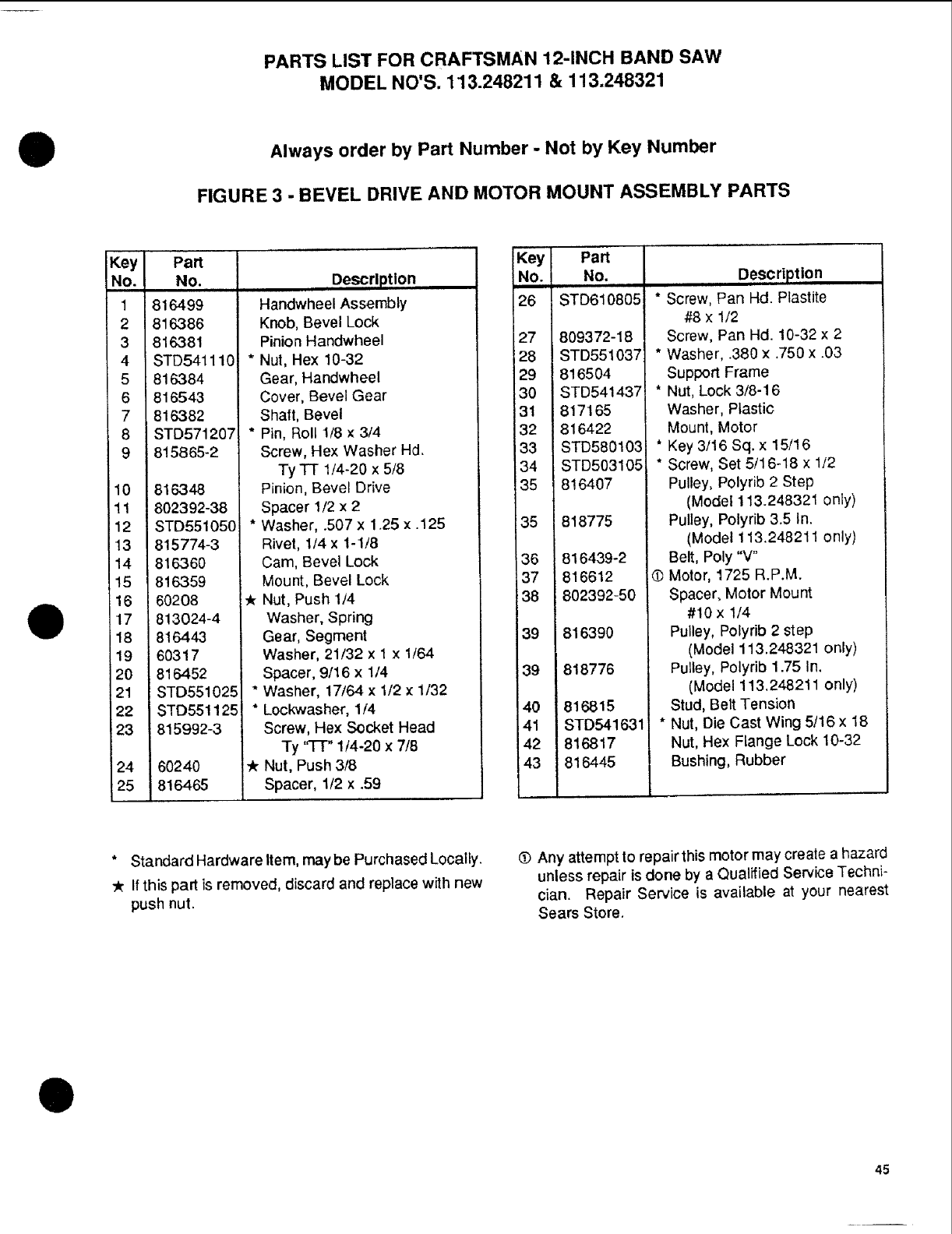
PARTS LIST FOR CRAFTSMAN 12-INCH BAND SAW
MODEL NO'S. 113.248211 & 113.248321
DAlways order by Part Number -Not by Key Number
FIGURE 3 -BEVEL DRIVE AND MOTOR MOUNT ASSEMBLY PARTS
t
Key
No.
1
2
3
4
5
6
7
8
9
10
11
12
13
14
15
18
17
18
19
20
21
22
23
24
25
Part
No.,,
816499
816386
816381
STD541110
816384
818543
816382
STD571207
81$865-2
816348
802392-38
STD551050
815774-3
816360
816359
60208
813024-4
816443
60317
816452
STD551025
STD551125
815992-3
60240
816465
Description
Handwheel Assembly
Knob, Bevel Lock
Pinion Handwheel
* Nut, Hex 10-32
Gear, Handwheel
Cover, Bevel Gear
Shaft, Bevel
* Pin, Roll 1/8 x 3/4
Screw, Hex Washer Hd,
Ty TT 1/4-20 x 5/8
Pinion, Bevel Drive
Spacer 1/2 x 2
* Washer, .507 x 1.25 x .125
Rivet, 1/4 x 1-1/8
Cam, Bevel Lock
Mount, Bevel Lock
Nut, Push 1/4
Washer, Spring
Gear, Segment
Washer, 21/32 x 1 x 1/64
Spacer, 9/16 x 1/4
* Washer, 17/64 x 1/2 x1/32
"Lockwasher, 1/4
Screw, Hex Socket Head
Ty 'q'T" 1/4-20 x 7/8
Nut, Push 3/8
Spacer, 1/2 x .59
Key Part
No. No.
26 STD610805
27 809372-18
28 STD551037
29 816504
30 STD541437
31 817165
32 816422
33 STD580103
34 STD503105
35 816407
35 818775
36 816439-2
37 816612
38 802392-50
39 816390
39 818776
40 616815
41 STD541 631
42 816817
43 816445
,Description
ii
* Screw, Pan Hd. Plastite
#8 x 1/2
Screw, Pan Hd. 10-32 x 2
* Washer, .380 x .750 x .03
Support Frame
* Nut, Lock 3/8-16
Washer, Plastic
Mount, Motor
* Key 3/16 Sq. x 15/16
* Screw, Set 5/16-18 x 1/2
Pulley, Polyrib 2 Step
(Model 113.248321 only)
PulJey, Polyrib 3.5 In.
(Model 113.248211 only)
Belt, Poly "V"
(_ Motor, 1725 R.P.M.
Spacer, Motor Mount
#10 x 1/4
Pulley, Polyrib 2 step
(Model 113.248321 only)
Pulley, Polydb 1.75 In.
(Model 113.248211 only)
Stud, Belt Tension
* Nut, Die Cast Wing 5/16 x 18
Nut, Hex Flange Lock 10-32
Bushing, Rubber
* Standard Hardware Item, may be Purchased Locally.
-_ If this part is removed, discard and replace with new
push nut.
(_ Any attempt to repair thismotor may create a hazard
unless repair is clone by aQualified Service Techni-
cian. Repair Service is available at your nearest
Sears Store.
45
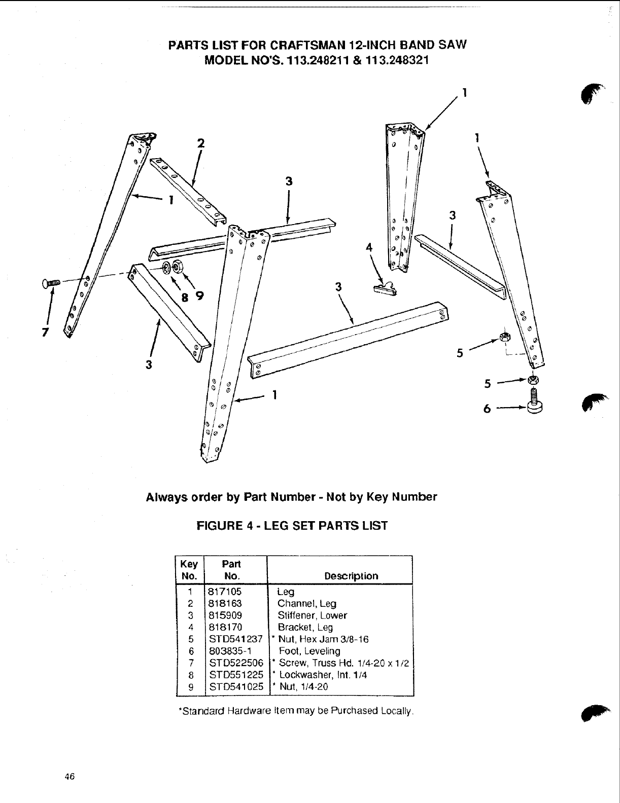
PARTS LIST FOR CRAFTSMAN 12-INCH BAND SAW
MODEL NO'S. 113.248211 & 113.248321
2
3
\
.,
Always order by Part Number -Not by Key Number
FIGURE 4 -LEG SET PARTS LIST
Key Pa_
No. No.
1 817105
2 818163
3 815909
4 818170
5 STD541237
6 803835-1
7 STD522506
8 STD551225
9 STD541025
Description
Leg
Channel, Leg
Stiffener, Lower
Bracket, Leg
*Nut, Hex Jam 3/8-16
Foot, Leveling
* Screw, Truss Hd. 1/4-20 x 1/2
* Lockwasher, Int. 1/4
* Nut, 1/4-20
*Standard Hardware Item may be Purchased Locally.
46

!
notes
il
0
47
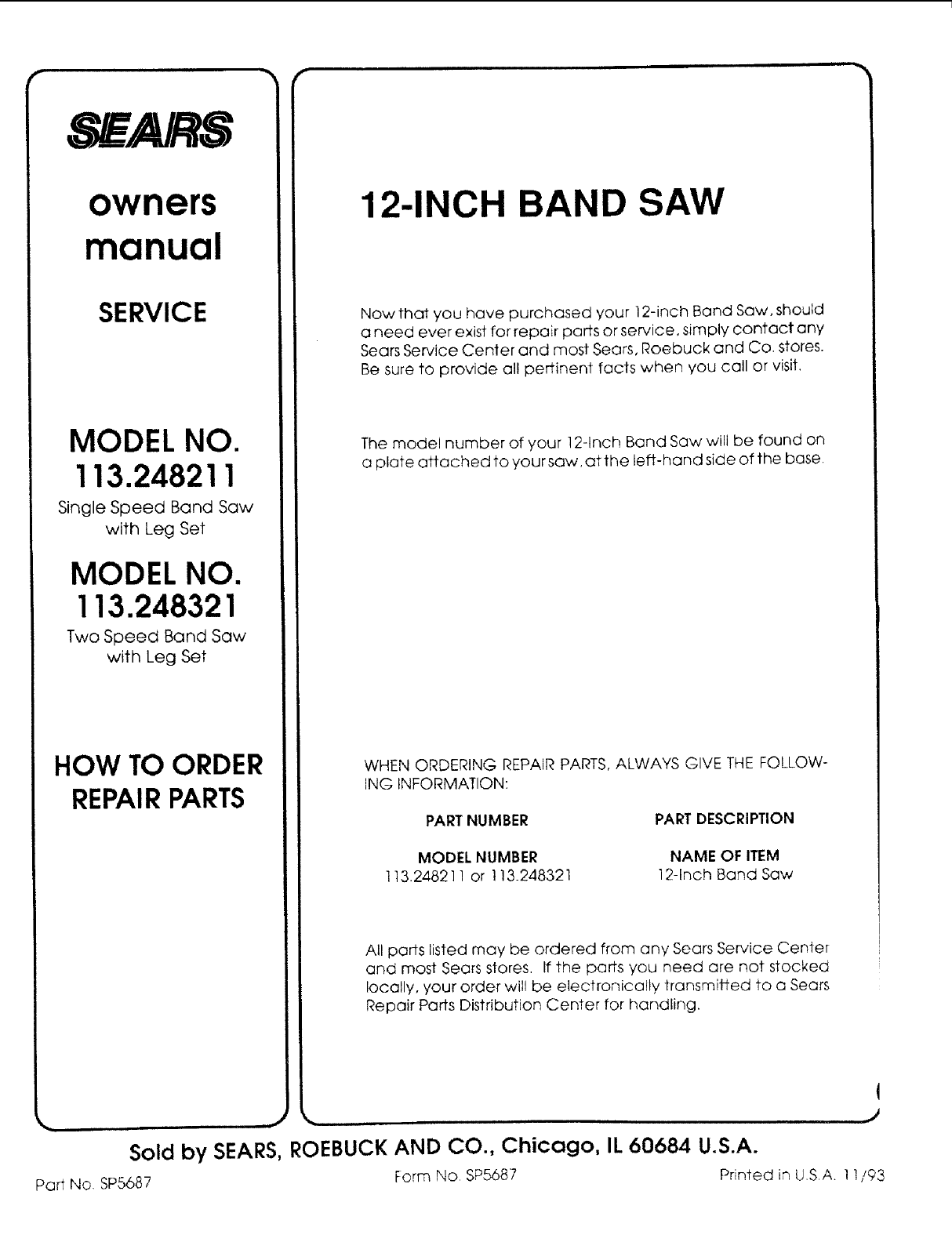
owners
manual
SERVICE
MODEL NO.
113.248211
Single Speed Band Saw
with Leg Set
12-INCH BAND SAW
MODEL NO.
113.248321
Two Speed Band Saw
with Leg Set
HOW TO ORDER
REPAIRPARTS
Now that you have purchased your 12-inch Band Saw, shoutd
a need ever exist for repair parts or service, simply contact any
Sears Service Center and most Sears, Roebuck and Co. stores.
Be sure to provide all pertinent facts when you call or visit.
The model number of your 12-Inch Band Saw will be found on
a plate attached to your saw, at the left-hand side of the base,
WHEN ORDERING REPAIR PARTS, ALWAYS GIVE THE FOLLOW-
ING INFORMATION:
PART NUMBER
MODEL NUMBER
113.24821 ! or 113.248321
PART DESCRIPTION
NAME OF ITEM
12-Inch Band Saw
All parts listed may be ordered from any Sears Service Center
and most Sears slores. If the parts you need are not stocked
locally, your order will be electronically transmiffed to a Sears
Repair Parts Distribution Center for handling.
Sold by SEARS, ROEBUCK AND CO., Chicago, IL 60684 U.S.A.
Form No SP5687
Part No. SP5687
q
Printed in U.S,A. 11/93
