Craftsman 11327521 User Manual BENCH SAW 10 INCH TILTING ARBOR. Manuals And Guides 1008043L
User Manual: Craftsman 11327521 11327521 CRAFTSMAN CRAFTSMAN BENCH SAW 10-INCH TILTING ARBOR. - Manuals and Guides View the owners manual for your CRAFTSMAN CRAFTSMAN BENCH SAW 10-INCH TILTING ARBOR. #11327521. Home:Tool Parts:Craftsman Parts:Craftsman CRAFTSMAN BENCH SAW 10-INCH TILTING ARBOR. Manual
Open the PDF directly: View PDF ![]() .
.
Page Count: 8
OPERATING INSTRUCTIONS
AND PARTS LIST FOR
C|smqE
10-inch Tilting Arbor
, , Model Number
113.27521
The above Model Number will be found on a plate attached to
your saw, at the back, near the bottom of the base. Always men-
tion the Model Number when communicating with us regarding
your saw or when ordering parts.
Instructions for Ordering Parts
All parts listed herein must be ordered through a Sears retail store
or mail order house. Parts are shipped prepaid. When ordering
repair parts, always give the following information:
1. The part number.
2. The part name.
3. The model number,
This list is valuable. It will assure your being able to obtain
proper parts service. We suggest you keep it with other valuable
papers.
........... ii i • i
ii
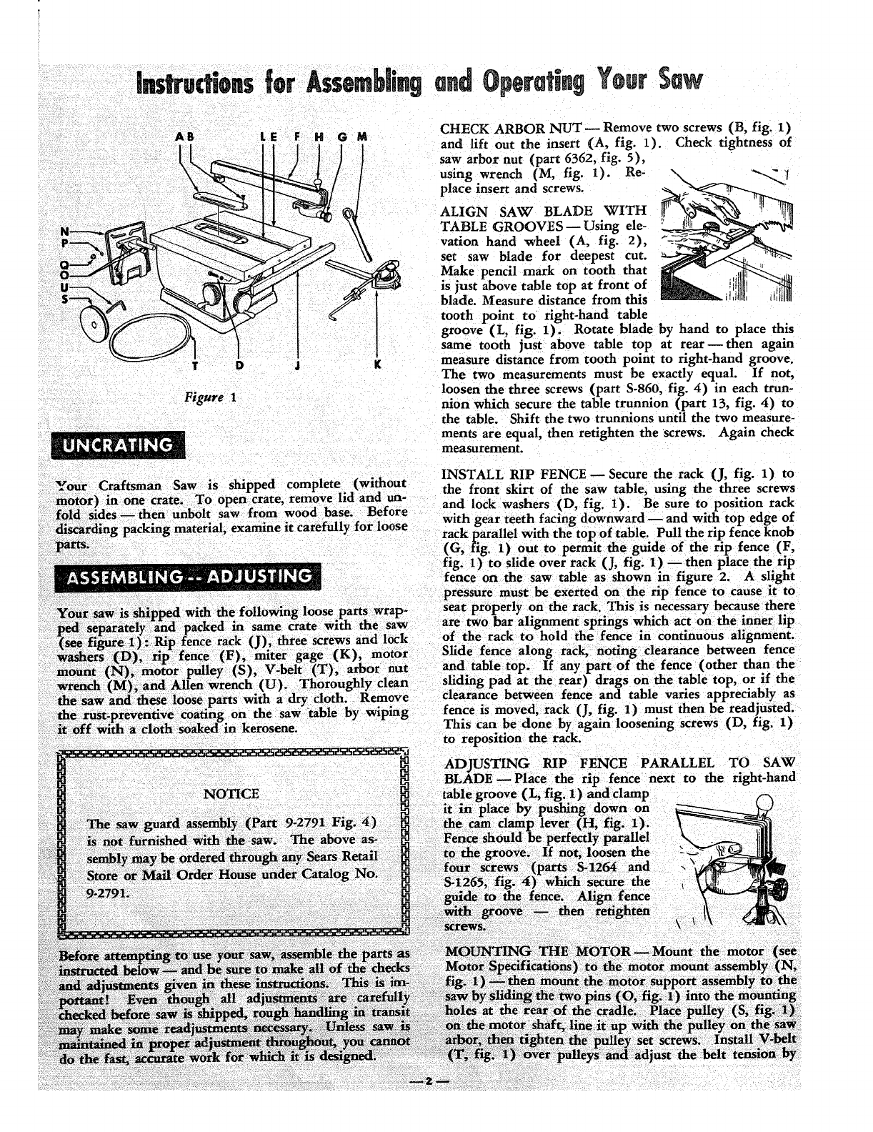
AB LE F
T D J
Figure 1
CHECK ARBOR NUT- Remove two screws (B, fig. 1)
Check tightness of
H O Mand lift out the insert (A, fig. 1).
[saw arbor nut (part 6362, fig. 5),
/using wrench (M, fig. 1). Re- ""--_'I
place insert and screws.
!ALIGN SAW BLADE WITH
TABLE GROOVES- Using ele-
vation hand wheel (A, fig. 2),
set saw blade for deepest cut.
Make pencil mark on tooth that
is just above table top at front of
blade. Measure distance from this
tooth point to right-hand table
groove (L, fig. 1). Rotate blade by hand to place this
same tooth just above table top at rear then again
g measure distance from tooth point to right-hand groove.
The two measurements must be exactly equal. If not,
loosen the three screws (part S-860, fig. 4) in each trun-
nion which secure the table trunnion (part 13, fig. 4) to
the table. Shift the two trunnions until the two measure-
ments are equal, then retighten the screws. Again check
measurement.
_our INSTALL RIP FENCE- Secure the rack (J, fig. 1) to
examine it carefully for loose rack parallel with the top of table. Pull the rip fence knob
(G, fig 1) out to pera_it the guide of the rip fence (F,
fig. 1)to slide over rack (J, fig. 1 ) then place the. rip
fence on the saw table as shown in figure 2. A shght
pressure must be exerted on the rip fence to cause it to
NOTICE
Slide fence along rack, noting clearance between fence
and table top. If any part of the fence (other than the
sliding pad at the rear) drags on the table top, or if the
clearance between fence and table varies apl_reciably as
fenc( is (j, fig. 1) must then be readjusted.
This again loosening screws (D, fig. 1)
to
;PARALLEL TO SAW
next to the right-hand
Fence
\
and
the _
moving the motor support assembly towards or away from
the cradle. Motor should be allowed to rest or hang
against the belt to obtain the automatic belt tightening
feature- and belt should be snug. If adjustment is cor-
rect, clamp the motor support in place by tightening the
two square head set screws (part S-1267, fig. 4).
ADJUSTING MOTOR MOUNT TENSION, Tension
is adjusted by tightening the nut (part S-1215, fig. 4)
against the steel washer (part S-1261) and the spring
washer (part 6423). Nut should be tightened just enough
to reduce motor vibration when saw is operating. Do
NOT tighten nut to alocked position, or the stud will be
sheared off when blade is raised or lowered. A sliding
action is necessary because mount changes position as
blade is raised or lowered. Operate the saw by hand to
make certain that the belt has proper tension and that
mount changes position as it should.
If saw is to be driven by a large frame motor that cannot
be mounted on the motor support assembly, mount the
motor on motor rails. Use a 1/2-inch wide belt with a
minimum length of 80 inches. Adjust the position of the
motor until belt clears all obstructions through all po-
sitions of the saw blade.
If saw is to be driven from a line shaft, use abelt at least
100 inches long.
PLACEMENT OF MITER GAGE- The miter gage as-
sembly (K, fig. 1) can be used in either one of the two
table grooves.
This saw is designed to be used with a3450 rpm motor.
Motor should be 3/4 hp (for light duty) or one hp (for
heavy duty)- in either an AC motor of arepulsion-
induction or capacitor type, or a compound-wound DC.
The motor shaft center siaould be approximately 4inches
above the bottom of the motor base. If this dimension
varies appreciably from 4inches, it may be necessary to
obtain abelt of adifferent length. If a 1750 rpm motor
with a 4-5/8-inch shaft center height is used, a 5-inch
motor pulley and a 46-inch belt must be purchased. If
the motor shaft center height varies greater or smaller
than the above dimension, a correspondingly greater or
smaller belt length should be used. _hese may be ordered
through any Sears Retail Store or Mail Order House.
CAUTION
Under no circumstances should a5-inch motor
Figure 2
ELEVATION HAND WHEEL (A)- on the front of
the saw, controls elevation of the blade.
CLAMP SCREW HANDLE (D) on front of saw, locks
the tilt mechanism in any desired position. The
clamp screw handle operates like a socket wrench.
Tilt mechanism should always be locked before start-
ing work and should always be unlocked before
attempting to change the angle of tilt.
TILT HAND WHEEL (B) on left side of saw, con-
trois the angle of tilt. The saw blade can be tilted
from 0°to 45 °, as indicated on the TILT GAGE
(C). If the angle of cut (tilt) must be extremely_
accurate, the angle of the saw blade should be
checked with a protractor or with a board which is
known to be cut at the exact angle required.
RIP FENCE (E) -- is operated by pushing in the FENCE
KNOB (F) so that it engages apinion gear with
the teeth on RACK (H). Turning the knob (F),
after pushing it in, will cause the rip fence to move
accurately across the table. When the knob (F) is
pulled out to disengage pinion gear, the rip fence
can be moved across the table by hand. Keep the
saw table and rip fence clean. Dirt may prevent the
rip fence from obtaining proper alignment. Tapping
the fence lightly to assist the mechanism to find its
natural position, will help to maintain alignment of
the fence with the blade.
CAM CLAMP LEVER (G)m is used to clamp the rip
fence in place after it has been moved to the position
desired.
MITER GAGE (J) w is used in table grooves as a guide
for the workpiece when the fence is not used. The
angle of the gage can be adjusted by loosening
CLAMP KNOB (K) and positioning gage as indi-
pulley be used with a 3450 rpm motor. The saw
blade speed resulting from such apulley ratio cated by the dial and pointer on (J).
would be dangerous. Do not use a 2fi_-inch MITER GAGE STOP ROD (L)--can be adjusted in
motor pulley _Tith a 1750 rpm motor --_is will length by loosening WING NUT (M). TI_ rod is
not ive satisfactory saw erformance, useci as a positioning guide for the end of the work-
gPptece.
The ¸ their uses. See figure 2.
_3_
CAUTION
Under no circumstances sh_d a blade with a
diameter greater than 10 inches: be _ with
this saw.
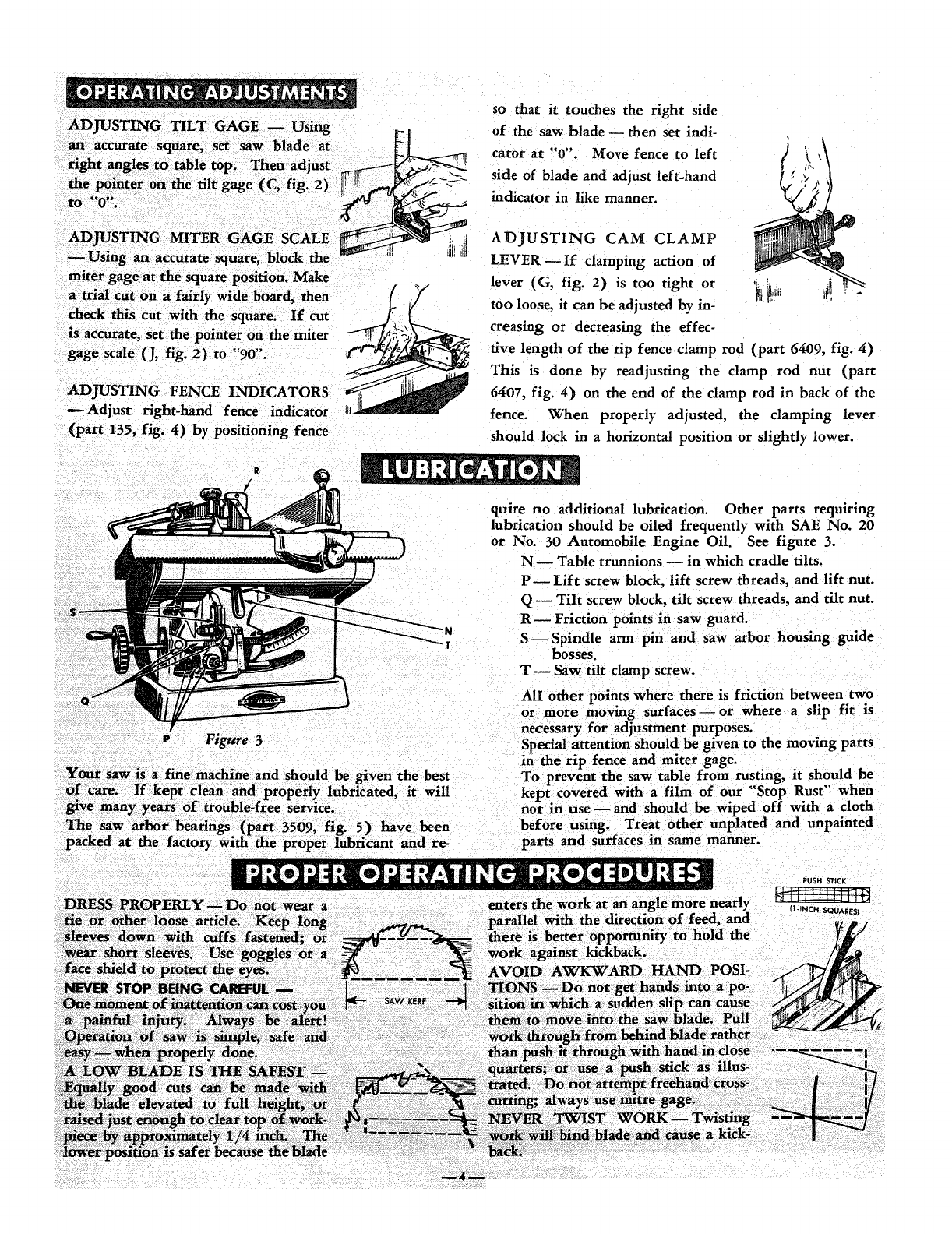
ADJUSTING TILT GAGE -- Using
an accurate square, set saw blade at _-L_
right angles tO table top. Then adjust
the pointer on the tilt gage (C, fig. 2)
to 0.
ADJUSTI OMITER SCALE
Using an accurate square, block the _ i_
check this cut with the square. If cut
is accurate, set the pointer on the miter
gage scale (J, fig. 2)to "90".
ADJUSTING FENCE II_
_Adjust right-hand fence indicator
(part 135, fig. 4) by positioning fence
so that it touches the right side
of the saw blade- then set indi-
qtO_S
cator at . Move fence to left
side of blade and adjust left-hand
indicator in like manner.
ADJUSTING CAM CLAMP
LEVER If clamping action of
lever (G, fig. 2) is too tight or '_!ili lid! -
too loose, it can be adjusted by in-
creasing or decreasing the effec-
tive length of the rip fence clamp rod (part 6409, fig. 4)
This is done by readjusting the clamp rod nut (part
6407, fig. 4) on the end of the clamp rod in back of the
fence. When properly adjusted, the clamping lever
should lock in a horizontal position or slightly lower.
Figure 3
quire no additional lubrication. Other parts requiring
lubrication should be oiled frequently with SAE No. 20
or No. 30 Automobile Engine Oil. See figure 3.
1N Table trunnions m in which cradle tilts.
PLift screw block, lift screw threads, and lift nut.
Q -- Tilt screw block, tilt screw threads, and tilt nut.
R--Friction points in saw guard.
-T S--Spindle arm pin and saw arbor housing guide
bosses.
T--Saw tilt clamp screw.
AII other points where there is friction between two
or more moving surfaces or where a slip fit is
necessary for adjustment purposes.
Special attention should be given to the moving parts
in the rip fence and miter gage.
PUSH STICK
enters the work at an angle more nearly
parallel with the direction of feed. ancl .,NO.SOUARES,
there iS better opportunity to hold the
work against kicf_back.
/
/
/
I/
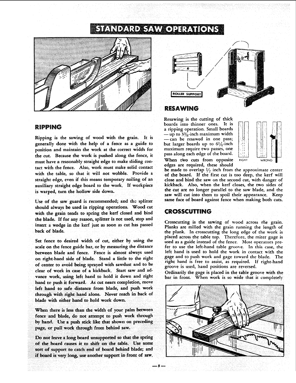
RiPPiNG
Ripping is the sawing of wood with the grain. It is
generally done with the help of afence as a guide to
position and maintain the work at the correct width for
the cut. Because the work is pushed along the fence, it
must have areasonably straight edge to make sliding con-
tact with the fence. Also, work must make solid contact
with the table, so that it will not wobble. Provide a
straight edge, even if this means temporary nailing of an
auxiliary straight edge board to the work. If workpiece
is warped, turn the hollow side down.
Use of the saw guard is recommended; and the splitter
should always be used in ripping operations. Wood cut
with the grain tends to spring the kerr closed and bind
the blade. If for any reason, splitter is not used, stop and
insert a wedge in the kerf just as soon as cut has passed
back of blade.
Set fence to desired width of cut, either by using the
scale on the fence guide bar, or by measuring the distance
between blade and fence. Fence is almost always used
on right-hand side of blade. Stand a little to the right
of center to avoid being sprayed with sawdust and to be
clear of work in case of a kickback. Start saw and ad-
vance work, using left hand to hold it down and right
hand to push it forward. AS cut nears completion, move
left hand to safe distance from blade, and push work
through with right hand alone. Never reach in back of
blade with either hand to hold work down.
When there is less than the
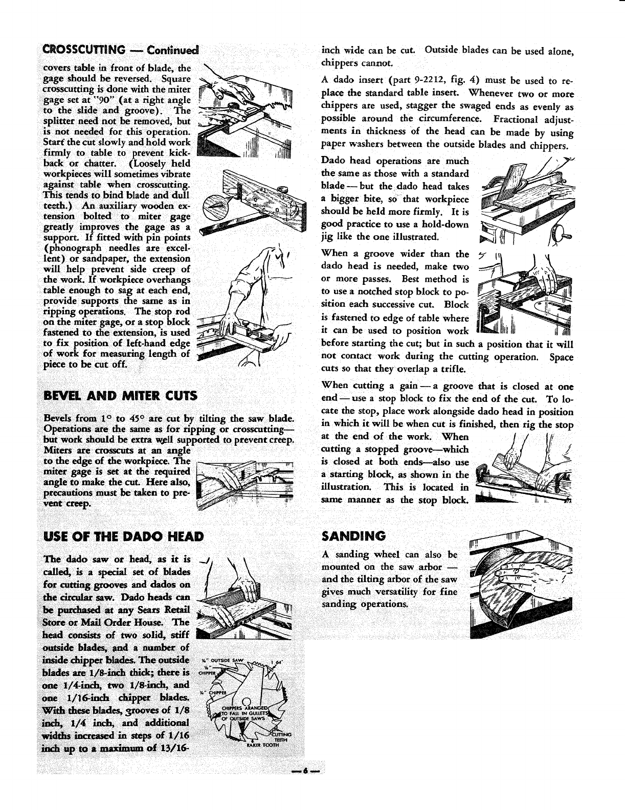
RESAWmNG
Resawing is the cutting of thick
boards into thinner ones. It is
a ripping operation. Small boards
up to 3_8-inch maximum width
--can be resawed in one pass;
but !arger boards up to 6l/_-inch
maximum require two passes, one
pass along each edge of the board.
When two cuts from opposite
edges are required, these should RHT
be made to overlap 1/2 inch from the approximate center
of the board. If the first cut is too deep, the kerr will
close and bind the saw on the second cut, with danger of
kickback. Also, when the kerr closes, the two sides of
the cut are no longer parallel to the saw blade, and the
saw will cut into them to spoil their appearance. Keep
same face of board against fence when making both cuts.
CROSSCUTTING
Crosscutting is the sawing of wood across r_ie grain.
Planks are milled with the grain running the length of
the plank. In crosscutting the long edge of the work is
placed across the table top. Therefore. the miter gage is
used as a guide instead of the fence. Most operators pre-
fer to use the left-hand table groove. In this case, the
left hand is used to hold the work in contact with the
gage and to push work and gage toward the blade. The
right hand is free to assist, as required. If right-hand
groove is used, hand positions are reversed.
Ordinarily the gage is placed in the table groove with the
bar in front. When work is so wide that it completely
saw.
and
mSm
CROSSCUTTING mContinued
covers table in front of blade, the
gage should be reversed. Square __
cr scuttlngisdonewiththe;niter
gage set at "90" (at a right angle __f,_,_
to the slide and groove). "l-'he _-'_
splitter need not im removed, but
is not needed for this operation.
Start_ the cut slowly and hold work _ luIlt_
firmly to table to prevent kick- _ii',iUlltl tlllll_
back or Chatter. (Loosely held
workpieces will sometimes vibrate
against table when crosscutting.
tends to bind blade and dull
teeth.) An auxiliary wooden ex-
tension bolted to miter gage
greatly improves the gage as a
sup oft If fitted with pin points
p •
(phonograph needles are excel- /_fw_
lent) or sandpaper, the extension ://_ €
will help prevent side creep of _/}(I \_
the work. If workpiece overhangs '_ '_----"
table enough to sag at each end, _/_
provide.. supports the same as in
rtppmg operations. The stop rod _/: t\
on the miter gage, or a stop block _/_ _._' :_i
fastened to _e _ension, is used ___, I"
to fix position of left-hand edge __/_/
of work for measuring length of
inch wide can be cut. Outside blades can be used alone,
chippers cannot.
A dado insert (part 9-2212, fig. 4) must be used to re-
place the standard table insert. Whenever two or more
chippers are used, stagger the swaged ends as evenly as
possible around the circumference. Fractional adjust-
ments in thickness of the head can be made by using
paper washers between the outside blades and chippers.
Dado head operations are much
the same as those with a standard
blade _ but the dado head takes
a bigger bite, so that workpiece
should be held more firmly. It is
good practice to use a hold-down
jig like the one illustrated.
When a groove wider than the _-
dado head is needed, make two
or more passes. Best method is
to use a notched stop block to po-
sition each successive cut. Block
is fastened to edge of table where
it can be used to position work
before starting the cut; but in such a position that it will
not contact work during the cutting operation. Space
cuts so that they overlap a trifle.
When cutting a gain _ a groove that is closed at one
BEVEL AND MITER CUTS end use a stop block to fix the end of the cut. To lo-
cate the stop, place work alongside dado head in position
Bevels from 1°to 45°are cut by tilting the saw blade in wh ...............
Operations are me"same as for ripping'" or crosscutu'ng_" mn It wm De when cut Is nmsneo, then rig the stop
but work should be extra well sup_ortecl to prevent creep, at the end of the work. When
Miters are crosscuts at an angle cutting astopped groove---which
to the edge of the workpiece. The _is closed at both ends--also use
miter gage is set at the required a starting block, as shown in the I
angle to make the cut. Here also, •..... _._ ......
•"-- "- ' n -rumstratlon. £111S lS locatea In
precauuons must De rage to p e-
vent same manner as the stop block.
creep. _ .i: _:
USE OF THE DADO HEAD
The dado saw or head, as it is
SANDING
Asanding
mounted
'forfine
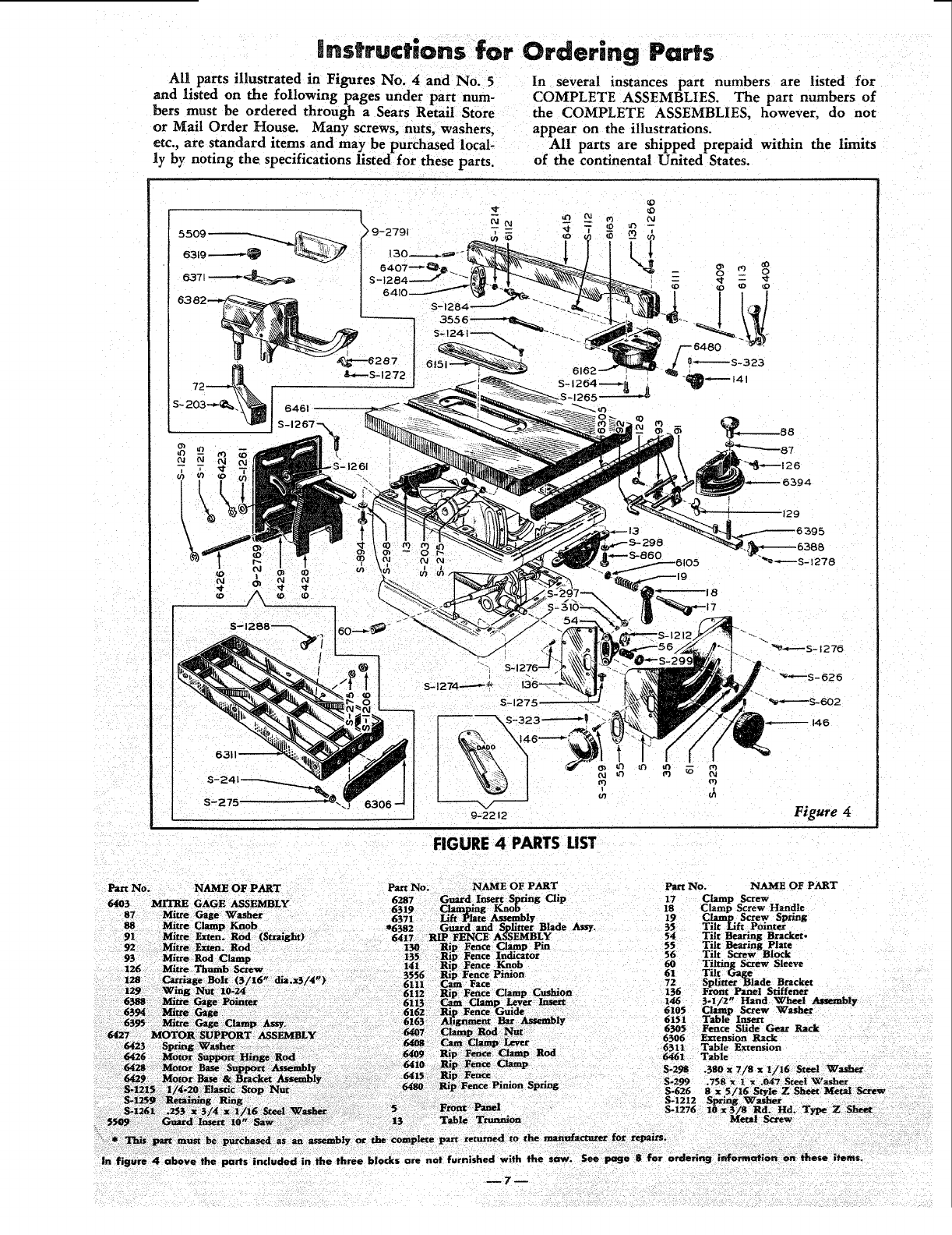
instructions for Ordering Parts
All parts illustrated in Figures No. zi and No. 5
and listed on the following pages under part num-
bers must be ordered through a Sears Retail Store
or Mail Order House. Many screws, nuts, washers,
etc., are standard items and may be purchased local-
ly by noting the specifications listed for these parts.
In several instances part numbers are listed for
COMPLETE ASSEMBLIES. The part numbers of
the COMPLETE ASSEMBLIES, however, do not
appear on the illustrations.
All parts are shipped prepaid within the limits
of the continental United States.
6461
S-1267-N_
S- 1274----_ _
9-2212
FIGURE 4 PARTS LIST
Part NO. NAME OF PART
64[03 MITRE GAGE ASSEMBLY
87 Mitre Gage Washer
88 Mitre Clamp Knob
91 Mitre Exten. Rod (S_aight)
92 Mitre F,xten. Rod
93 Mitre Rod Clamp
126 Mitre Thumb Screw
Part No. NAME OF PART Part No. NAME OF PART
17 Clamp Screw
18 Clamp Screw Handle
19 Clan_p Screw Spring
55 Tilt Lift Pointer
54 Tilt Bearing Bracket.
55 Tilt Bearing Plate
56 Tilt Screw Block
, Rod
6_;05 Fence Sfide Gear Rack
6506 Extension Rack
6511 Table Extension
6461 Table
S-298 380 x 7/8 x I/t6 Steel Washer
Front Panel
Table Tnmnion
ot the complete pare _cetumed to the manufacturer for repairs.
parts included in the three blocks are not furnished with the saw. See page :8 for ordering l_rmc_ien on these items.
0
J
S- 1289
Figure 5
FIGURE 5 PARTS LIST
Part No. NAME OF PART Part No. NAME OF PART
6392 SAW ARBOR HOUSING ASSY. 47 Saw Arbor Retaining Stud
27 Loose Collar 30 Spindle .Arm Retaining Washer,
3508 Arbor Bearing Retaivex 38 Lift Screw Block
3509 Saw Arbor Bearing 39 Lift Nut
3513 Saw Arbor Key 58 Tilt Nut
6362 Saw Arbor Nut * 69 Splitter Blade Clamp Washer
6383 Saw Arbor Shaft Snap Ring * 70 Splitter Blade Clamp Spring
6393 Saw Arbor Assembly 3540 Arbor Wrench
6380 Saw Arbor Housing 3557 Lift Nut Washer
S-I211 Spring Washer 6084 Tilting Screw Spacer
5570 CRADLE h_SSEMBLY
14 Cradle 6085 Saw Arbor Retaining Stud
15 Spindle Arm Pin Washer
Part No. NAME OF PART
6302 Tilt Lift Nut Bracket
6326 Lift Screw Collar
6328 Lift Screw
6331 Retaining Ring
6355 Saw Base Assembly
6451 Stop Collar
6459 Tilt Screw
* S-970 7/16 x3/4 x .0239 Steel Washer
* S-1066 7/16 x 3/4 x.0299 Steel Washer
S.1212 Spring Washer
S-1262 Spring Washer
8-1271 .758 x 1 x 1/32 Fibre Washer
S-1283 .695 x 15/16 x 1/64 Steel Washer
The following parts shown on Figures 4 and 5are standard and can be purchased locally:
Part No. NAME OF PART Part No. NAME OF PART Part I_o. NAME OF PART
S-112 10---32 x 1/2 Fil. Hd. Mach. * S-1090 S-1266 8---32 x5/16 Pan Hd. or Rd.
Screw Hd. Mach. Screw
S-203 5/16---18 x 3/4 Hex. Hd. Cap S-1156 9/16 x 1-3/8 x 7/64 Flat Steel S-1267 5/16--18 x 5/8 Sq. Hd. Set Screw
Screw Washer S*1268 5/16--18 x 1-3/16 Her. Hd.
_2_1 5/i6"/-18X Cap Screw
S.... _crew 7/8 Hex. Hd. Cap S-1204 1/2...-13 x 13/16 x7/16 Hex. Nut S-1272 8---32 x 5/16 Pan Hd. Math. Screw
S-275 5/16 SAE Med. Lockwashe_ S-1205 1/2--13 x15/16 x 5/16 Jam Nut S-1274 10--32 x 3/8 x 1/8 Hex. Nut
S-1206 5/16--18 x 7/32 Hex. Nut S-1275 10---32 x 1/2 Rd. Hd. Math. Screw
