Craftsman 12632561 User Manual MITER SAW Manuals And Guides 1209721L
User Manual: Craftsman 12632561 12632561 CRAFTSMAN MITER SAW - Manuals and Guides View the owners manual for your CRAFTSMAN MITER SAW #12632561. Home:Tool Parts:Craftsman Parts:Craftsman MITER SAW Manual
Open the PDF directly: View PDF ![]() .
.
Page Count: 92
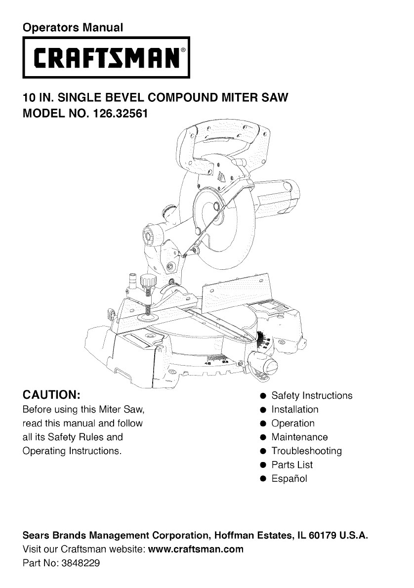
Operators Manual
CRItFTSMI:INi
10 IN. SINGLE BEVEL COMPOUND MITER SAW
MODEL NO. 126.32561
CAUTION:
Before using this Miter Saw,
read this manual and follow
all its Safety Rules and
Operating Instructions.
• Safety Instructions
• Installation
• Operation
• Maintenance
• Troubleshooting
• Parts List
• Espa_ol
Sears Brands Management Corporation, Hoffman Estates, IL 60179 U.S.A.
Visit our Craftsman website: www.craftsman.com
Part No: 3848229

SECTION PAGE
Warranty .................................................................................................................................... 2
Product Specifications ............................................................................................................... 3
Symbols ..................................................................................................................................... 4
Power Tool Safety ...................................................................................................................... 5
Sliding Compound Miter Saw Safety ......................................................................................... 7
Electrical Requiretments and Safety .......................................................................................... 9
Accessories and Attachments ................................................................................................. 11
Tools Needed For Assembly .................................................................................................... 12
Carton Contents ...................................................................................................................... 13
Know Your Compound Miter Saw ............................................................................................ 14
Glossary of Terms .................................................................................................................... 16
Assembly and Adjustments ..................................................................................................... 18
Operation ................................................................................................................................. 26
Maintenance ............................................................................................................................ 39
Troubleshooting Guide ............................................................................................................ 41
Parts List .................................................................................................................................. 43
CRAFTSMAN ONE YEAR FULL WARRANTY
FOR ONE YEAR from the date of purchase, this product is warranted against defects
in material or workmanship. A defective product will receive free or replacement if repair is
unavailable. For warranty coverage details to obtain free repair or replacement,
visit the web site: www.craftsman.com
This warranty does not cover the blade which is an expendable part that can wear out
from normal use within the warranty period. This warranty is void if this product is ever
used while providing commercial services or if rented to another person. This warranty
gives you specific legal rights, and you may also have other rights which vary from state to state.
Sears Brands Management Corporation, Hoffman Estates, IL 60179
,_ WARNING l
Some dust created by using power tools contains chemicals known to the state of California
to cause cancer and birth defects or other reproductive harm. Some examples of these
chemicals are: • Lead from lead-based paints
• Crystalline silica from bricks, cement and other masonry products
• Arsenic and chromium from chemically treated lumber
Your risk from these exposures varies, depending on how often you do this type of work. To
reduce your exposure to these chemicals, work in a well ventilated area and work with approved
safety equipment such as dust masks that are specially designed to filter out microscopic particles.
2
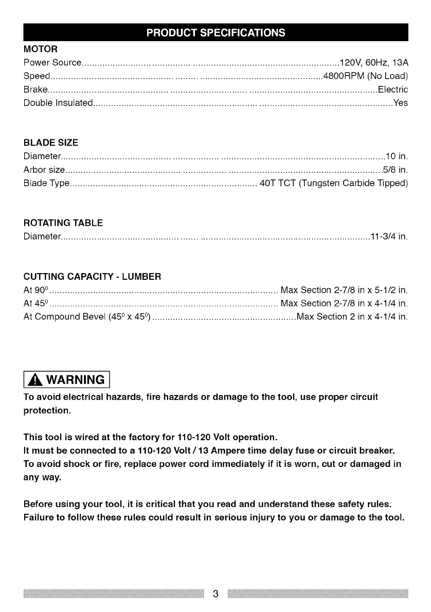
MOTOR
Power Source ................................................................................................... 120V, 60Hz, 13A
Speed ......................................................................................................... 4800RPM (No Load)
Brake ............................................................................................................................... Electric
Double Insulated .................................................................................................................... Yes
BLADE SIZE
Diameter ............................................................................................................................. 10 in.
Arbor size .......................................................................................................................... 5/8 in.
Blade Type ......................................................................... 40T TCT (Tungsten Carbide Tipped)
ROTATING TABLE
Diameter ....................................................................................................................... 11-3/4 in.
CUTTING CAPACITY- LUMBER
At 90o......................................................................................... Max Section 2-7/8 in x 5-1/2 in.
At 45o......................................................................................... Max Section 2-7/8 in x 4-1/4 in.
At Compound Bevel (45 ox 45°) ........................................................ Max Section 2 in x 4-1/4 in.
[,_ WARNING l
To avoid electrical hazards, fire hazards or damage to the tool, use proper circuit
protection.
This tool is wired at the factory for 110-120 Volt operation.
It must be connected to a 110-120 Volt /13 Ampere time delay fuse or circuit breaker.
To avoid shock or fire, replace power cord immediately if it is worn, cut or damaged in
any way.
Before using your tool, it is critical that you read and understand these safety rules.
Failure to follow these rules could result in serious injury to you or damage to the tool.
3
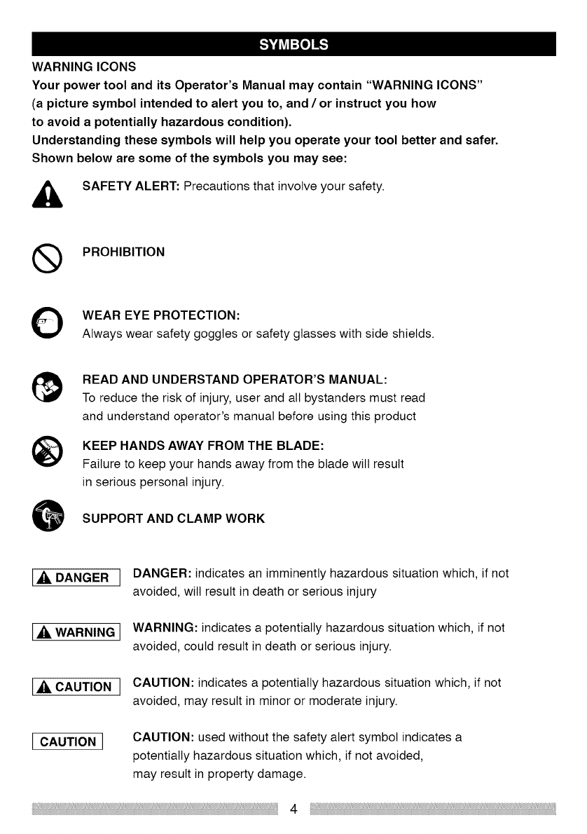
WARNING ICONS
Your power tool and its Operator's Manual may contain "WARNING ICONS"
(a picture symbol intended to alert you to, and /or instruct you how
to avoid a potentially hazardous condition).
Understanding these symbols will help you operate your tool better and safer.
Shown below are some of the symbols you may see:
_, SAFETY ALERT: Precautions that involve your safety.
(_ PROHIBITION
WEAR EYE PROTECTION:
Always wear safety goggles or safety glasses with side shields.
READ AND UNDERSTAND OPERATOR'S MANUAL:
To reduce the risk of injury, user and all bystanders must read
and understand operator's manual before using this product
KEEP HANDS AWAY FROM THE BLADE:
Failure to keep your hands away from the blade wilt result
in serious personal injury.
SUPPORT AND CLAMP WORK
L,_. DANGER J DANGER: indicates an imminently hazardous situation which, if not
avoided, will result in death or serious injury
l,_ WARNING J WARNING: indicates a potentially hazardous situation which, if not
avoided, could result in death or serious injury.
L,_. CAUTION JCAUTION: indicates a potentially hazardous situation which, if not
avoided, may result in minor or moderate injury.
lCAUTION 1CAUTION: used without the safety alert symbol indicates a
potentially hazardous situation which, if not avoided,
may result in property damage.
4
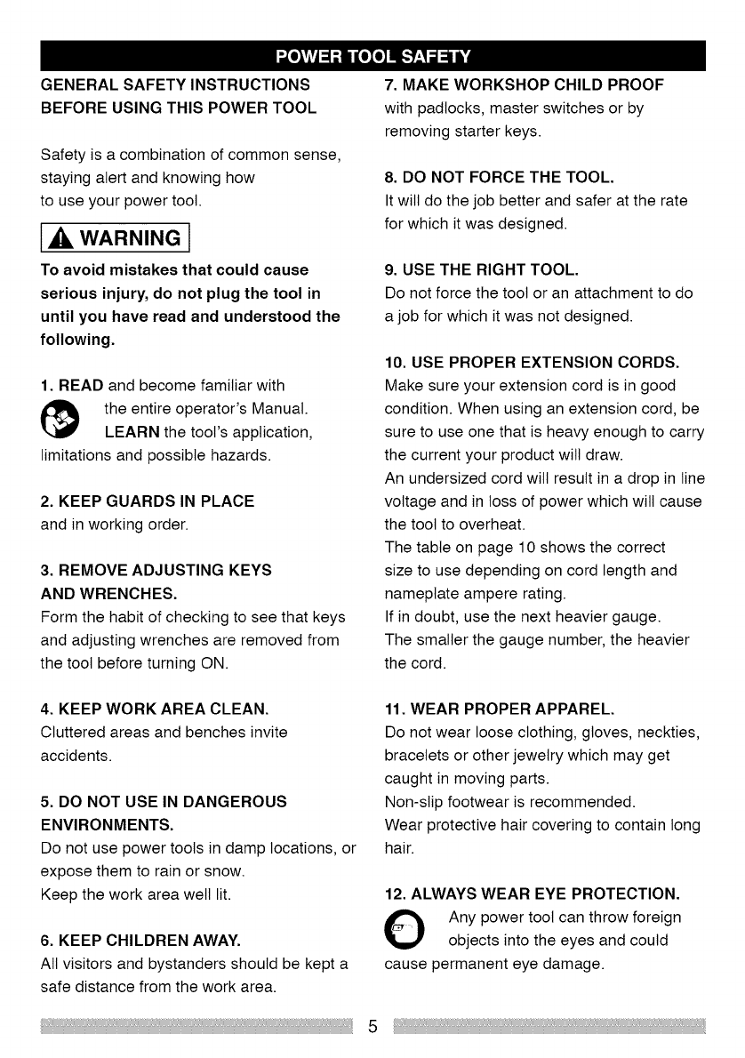
GENERAL SAFETY INSTRUCTIONS
BEFORE USING THIS POWER TOOL
Safety is a combination of common sense,
staying alert and knowing how
to use your power tool.
[,_ WARNING l
To avoid mistakes that could cause
serious injury, do not plug the tool in
until you have read and understood the
following.
1. READ and become familiar with
the entire operator's Manual.
LEARN the tool's application,
limitations and possible hazards.
2. KEEP GUARDS IN PLACE
and in working order.
3. REMOVE ADJUSTING KEYS
AND WRENCHES.
Form the habit of checking to see that keys
and adjusting wrenches are removed from
the tool before turning ON.
7. MAKE WORKSHOP CHILD PROOF
with padlocks, master switches or by
removing starter keys.
8. DO NOT FORCE THE TOOL.
It wilt do the job better and safer at the rate
for which it was designed.
9. USE THE RIGHT TOOL.
Do not force the tool or an attachment to do
a job for which it was not designed.
10. USE PROPER EXTENSION CORDS.
Make sure your extension cord is in good
condition. When using an extension cord, be
sure to use one that is heavy enough to carry
the current your product will draw.
An undersized cord wilt result in a drop in line
voltage and in loss of power which will cause
the tool to overheat.
The table on page 10 shows the correct
size to use depending on cord length and
nameplate ampere rating.
If in doubt, use the next heavier gauge.
The smaller the gauge number, the heavier
the cord.
4. KEEP WORK AREA CLEAN.
Cluttered areas and benches invite
accidents.
5. DO NOT USE IN DANGEROUS
ENVIRONMENTS.
Do not use power tools in damp locations, or
expose them to rain or snow.
Keep the work area well lit.
6. KEEP CHILDREN AWAY.
All visitors and bystanders should be kept a
safe distance from the work area.
11. WEAR PROPER APPAREL.
Do not wear loose clothing, gloves, neckties,
bracelets or other jewelry which may get
caught in moving parts.
Non-slip footwear is recommended.
Wear protective hair covering to contain long
hair.
12. ALWAYS WEAR EYE PROTECTION.
Any power toot can throw foreign
objects into the eyes and could
cause permanent eye damage.
5

ALWAYS wear Safety Goggles
(not glasses) that comply with
ANSI Safety standard Z87.1.
Everyday eyeglasses have only impact
resistant lenses.
They ARE NOT safety glasses.
Safety Goggles are available at Sears.
NOTE: Glasses or goggles not in compliance
with ANSI Z87.1 could seriously injure you
when they break.
13. WEAR A FACE MASK OR DUST MASK.
Sawing operations can produce dust.
14. SECURE WORK.
O Use clamps or a vice to hold work
when practicable.
It is safer than using your hand and it frees
both hands to operate the toot.
15. DISCONNECT TOOLS FROM
POWER SOURCE before servicing, and
when changing accessories such as
blades, bits and cutters.
16. REDUCE THE RISK OF
UNINTENTIONAL STARTING.
Make sure switch is in the OFF position
before plugging the tool in.
17. USE RECOMMENDED ACCESSORIES.
Consult this Operator's Manual for
recommended accessories.
The use of improper accessories may cause
risk of injury to yourself or others.
18. NEVER STAND ON THE TOOL.
Serious injury could occur if the cutting tool
is unintentionally contacted.
19. CHECK FOR DAMAGED PARTS.
Before further use of the tool, a guard or
other part that is damaged should be carefully
checked to determine that it will operate
properly and perform its intended function -
check for alignment of moving parts, binding
of moving parts, mounting and any other
conditions that may affect its operation. A
guard or other part that is damaged should be
properly repaired or replaced.
20. NEVER LEAVE THE TOOL RUNNING
UNATTENDED. TURN THE POWER "OFF".
Do not walk away from a running tool until
the blade comes to a complete stop and the
tool is unplugged from the power source.
21. DO NOT OVER-REACH.
Keep proper footing and balance at all times.
NEVER reach your hand or arm across the
path of the cutting blade.
22. MAINTAIN TOOLS WITH CARE.
Keep tools sharp and clean for best and
safest performance. Follow instructions for
lubricating and changing accessories.
23. WARNING: Dust generated from certain
materials can be hazardous to your health.
Always operate saw in well-ventilated area
and provide for proper dust removal.
I_,DANGER l
24. People with electronic devices, such
as pacemakers, should consult their
physician(s) before using this product.
Operation of electrical equipment in close
proximity to a heart pacemaker could cause
interference or failure of the pacemaker.
6

SPECIFIC SAFETY INSTRUCTIONS
FOR THIS SINGLE BEVEL COMPOUND
MITER SAW
10. BE SURE both the blade and the collar
are clean and the arbor bolt is tightened
securely.
1. DO NOT USE THIN KERF BLADES
they can deflect and contact guard and can
cause possible injury to the operator.
2. DO NOT operate the miter saw until
it is completely assembled and installed
according to these instructions.
3. IF YOU ARE NOT thoroughly familiar with
the operation of miter saws, seek guidance
from your supervisor, instructor or
other qualified person.
11. USE only blade collars specified for your
saw.
12. NEVER use blades larger in diameter
than 10 inches.
13. NEVER apply lubricants to the blade
when it is running.
14. ALWAYS check the blade for cracks or
damage before operation. Replace a cracked
or damaged blade immediately.
4. ALWAYS hold the workpiece firmly against
the fence and table. DO NOT perform any
operation freehand. Use a clamp to secure
the workpiece whenever possible.
5. KEEP HANDS out of the path of the saw
blade. If the workpiece you are cutting would
cause your hands to be within 6-3/8 in.of the
saw blade, the workpiece should be clamped
in place before making the cut.
15. NEVER use blades recommended for
operation at less than 5000 RPM.
16. ALWAYS keep the blade guards in place,
and use at all times.
17. NEVER reach around the saw blade.
18. MAKE SURE the blade is not contacting
the workpiece before the switch is turned ON.
6. BE SURE the blade is sharp, runs freely
and is free of vibration.
7. ALLOW the motor to come up to full
speed before starting a cut.
8. KEEP THE MOTOR AIR SLOTS CLEAN
and free of chips or dust.
9. ALWAYS MAKE SURE all handles are
tight before cutting, even if the table is
positioned in one of the positive stops.
19. IMPORTANT: After completing the cut,
release the trigger and wait for the blade to
stop before returning the saw to the raised
position.
20. MAKE SURE the blade has come to a
complete stop before removing or securing
the workpiece, changing the workpiece angle
or changing the angle of the blade.
7
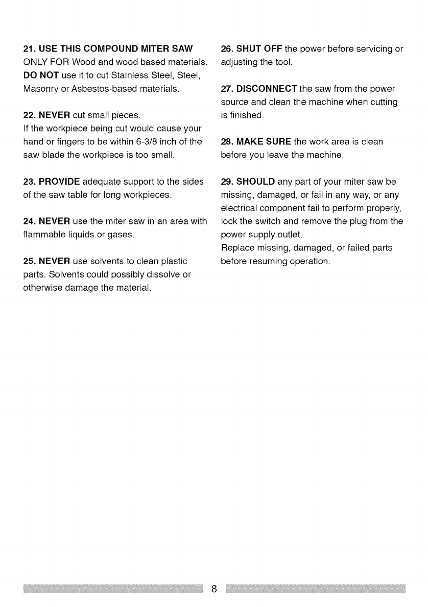
21. USE THIS COMPOUND MITER SAW
ONLY FOR Wood and wood based materials.
DO NOT use it to cut Stainless Steel, Steel,
Masonry or Asbestos-based materials.
22. NEVER cut small pieces.
If the workpiece being cut would cause your
hand or fingers to be within 6-3/8 inch of the
saw blade the workpiece is too small.
26. SHUT OFF the power before servicing or
adjusting the tool.
27. DISCONNECT the saw from the power
source and clean the machine when cutting
is finished.
28. MAKE SURE the work area is clean
before you leave the machine.
23. PROVIDE adequate support to the sides
of the saw table for long workpieces.
24. NEVER use the miter saw in an area with
flammable liquids or gases.
25. NEVER use solvents to clean plastic
parts. Solvents could possibly dissolve or
otherwise damage the material.
29. SHOULD any part of your miter saw be
missing, damaged, or fail in any way, or any
electrical component fail to perform properly,
lock the switch and remove the plug from the
power supply outlet.
Replace missing, damaged, or failed parts
before resuming operation.
8

WARNING l
POWER SUPPLY AND MOTOR
SPECIFICATIONS
The AC motor used in this saw is a universal,
non-reversible type. See "MOTOR" in the
"PRODUCT SPECIFICATIONS"
section on page 3.
To reduce the risk of electrical shock, this
saw has a polarized plug (one blade is wider
than the other). This plug will fit in a polarized
outlet only one way. If the plug does not fit
fully in the outlet, reverse plug. If it still does
not fit, contact a qualified electrician to install
the proper outlet. Do not change the plug in
any way.
,A WARNING l
To avoid electrical hazards, fire hazards,
or damage to the tool, use proper circuit
protection. Your saw is wired at the factory
for 120V operation. Plug the saw into a 120V,
15A electrical outlet. To avoid shock or fire, if
power cord is worn or cut, or damaged in any
way, have it replaced immediately.
DOUBLE INSULATED
This power toot is double insulated to provide
a double thickness of insulation between you
and the tool's electrical system. All exposed
metal parts are isolated from the internal
metal motor components with protecting
insulation.
Replacement parts -When servicing, use
only identical replacement parts.
Polarized plugs - This saw has a plug that
looks like the one shown below:
1_. WARNING I
Double insulation does not take the place of
normal safety precautions when
operating this toot.
To avoid electrocution:
1. Use only identical replacement parts
when servicing a tool with double insulation.
Servicing should be performed by
a qualified technician.
2. Do not use power tools in wet or damp
locations or expose them to rain or snow.
MOTOR SAFETY PROTECTION
IMPORTANT:
To avoid motor damage, the motor should be
blown out or vacuumed frequently to keep
dust from interfering with motor ventilation.
1. Plug the saw into a 120V, 15A electrical
outlet.
NOTE: When using an extension cord on a
circuit with a # 18 wire, the extension cord
must not exceed 25 feet in length.
2. If the motor will not start, release the
trigger switch immediately.
UNPLUG THE SAW. Check the saw blade
to make sure it turns freely.
9
If the blade is free, try to start the saw again.
If the motor still does not start, refer to the
TROUBLESHOOTING GUIDE.
3. If the tool suddenly stalls while cutting,
release the trigger switch and unplug the
tool. Free the blade from the workpiece.
Restart the machine and complete the cut.
4. FUSES may "blow" or circuit breakers
may trip if:
a. MOTOR is overloaded - overloading can
occur if you feed too rapidly or make too
many start /stops in a short time.
b. LINE VOLTAGE is more than 10% above
or below the nameplate voltage rating.
For heavy loads, the voltage at the motor
terminals must equal the voltage specified on
the nameplate.
c. IMPROPER or dull saw blades are used.
5. Most motor troubles can be traced to
loose or incorrect connections, overload, low
voltage or inadequate power supply wiring.
Always check the connections, the load and
the supply circuit if the motor does not run
welt. Check minimum gauge for the length of
cord you are using on the chart below.
GUIDELINES FOR EXTENSION
CORDS
Use a proper extension cord.
Make sure your extension cord is in good
condition. When using an extension cord,
be sure to use one that is heavy enough
to carry the current your product will draw.
An undersized cord wilt cause a drop in line
voltage, resulting in loss of power
and overheating.
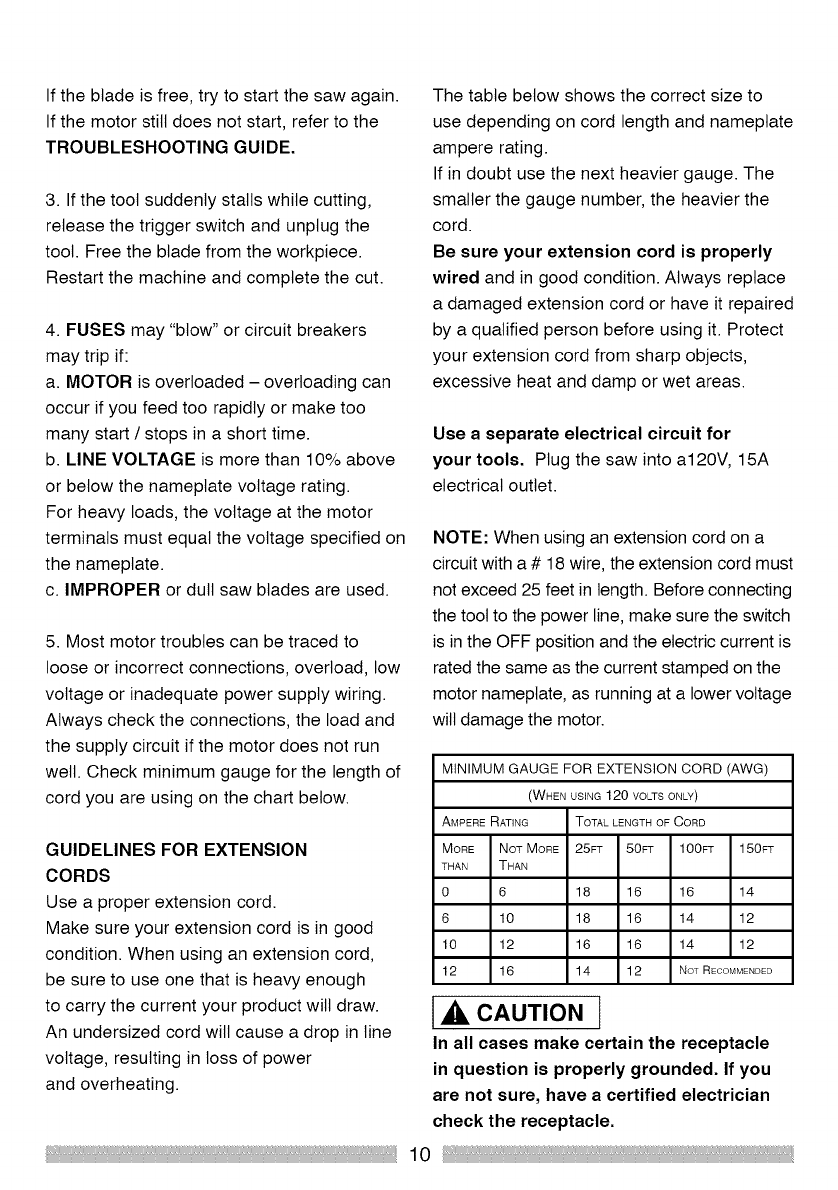
The table below shows the correct size to
use depending on cord length and nameplate
ampere rating.
If in doubt use the next heavier gauge. The
smaller the gauge number, the heavier the
cord.
Be sure your extension cord is properly
wired and in good condition. Always replace
a damaged extension cord or have it repaired
by a qualified person before using it. Protect
your extension cord from sharp objects,
excessive heat and damp or wet areas.
Use a separate electrical circuit for
your tools. Plug the saw into a120V, 15A
electrical outlet.
NOTE: When using an extension cord on a
circuit with a # 18 wire, the extension cord must
not exceed 25 feet in length. Before connecting
the tool to the power line, make sure the switch
is in the OFF position and the electric current is
rated the same as the current stamped on the
motor nameplate, as running at a lower voltage
will damage the motor.
MINIMUM GAUGE FOR EXTENSION CORD (AWG)
(WHEN USING 120 VOLTSONLY)
AMPERE RATING TOTAL LENGTH OF CORD
MORE NOT MORE 25FT 50FT 100FT 150PT
THAN THAN
0 6 18 16 16 14
6 10 18 16 14 12
10 12 16 16 14 12
12 16 14 12 NoTRECOMMENDED
_, CAUTION 1
In all cases make certain the receptacle
in question is properly grounded. Ifyou
are not sure, have a certified electrician
check the receptacle.
10
AVAILABLE ACCESSORIES
[,_ WARNING l
Use only accessories recommended
for this miter saw. Follow instructions
that accompany accessories.
Use of improper accessories may
cause hazards.
The use of any cutting tool except
10 in. saw blades which meet the
requirements under recommended
accessories is prohibited. Do not use
accessories such as shaper cutters
or dado sets. The use of abrasive
wheels is prohibited.
Do not attempt to modify this tool or
create accessories not recommended
for use with this tool. Any such
modification is misuse and could
result in a hazardous condition
leading to possible serious injury.
ACCESSORIES
Visit your Sears Hardware Department or see
the Craftsman Power and Hand Tool Catalogue
to purchase available accessories for this power
tool.
1_, WARNING j
To avoid the risk of personal injury,
do not modify this power tool or use
accessories that are not Craftsman
brand.
Read warnings and conditions on
your TCT BLADE.
(Tungsten Carbide Tipped)
Do not operate the saw without the
proper saw blade guard in place.
Carbide is a very hard material.
Care should be taken while mounting,
using and storing carbide tipped
blades to prevent accidental damage.
Shocks such as striking the tips while
handling can damage the blade.
Before using, always visually
examine the blade for cracks, missing
or loose tips, distortion or any other
damage. Do not use if any damage
is suspected. Failure to heed safety
instructions and warnings can result
in serious bodily injury.
11
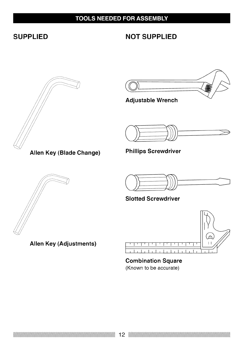
SUPPLIED NOT SUPPLIED
/
/
/
/
/
Allen Key (Blade Change)
Adjustable Wrench
Phillips Screwdriver
Allen Key (Adjustments)
Slotted Screwdriver
,I,1,t,t,I,I,1,1_1 _
Combination Square
(Known to be accurate)

UNPACKING YOUR MITER SAW
WARNING l
To avoid injury from unexpected starting
or electrical shock, do not plug the
power cord into a source of power during
unpacking and assembly.
The power cord must remain unplugged
when adjustments or maintenance to the
machine takes place.
1. Remove the miter saw from the carton.
IMPORTANT: Do not lift the miter saw by
the trigger switch handle. It may cause
misalignment.
2. Place the saw on a secure, stable work
surface.
3. Separate all the parts from the packing
material. Check each one with the
illustrations below to make certain that all
items are accounted for before discarding
any packing material.
l,_ WARNING i
If any part is missing or damaged do
not attempt to assemble the miter
saw, or plug in the power cord until
the missing or damaged part is
correctly replaced.
Call 1-800-469-4663 for missing or
damaged parts.
To avoid electric shock, use only
identical replacement parts when
servicing double insulated tools.
Call 1-800-469-4663 for
replacement parts.
i
Hold Down Clamp
Dust Bag Allen Keys
10 Inch Single Bevel Miter Saw
13
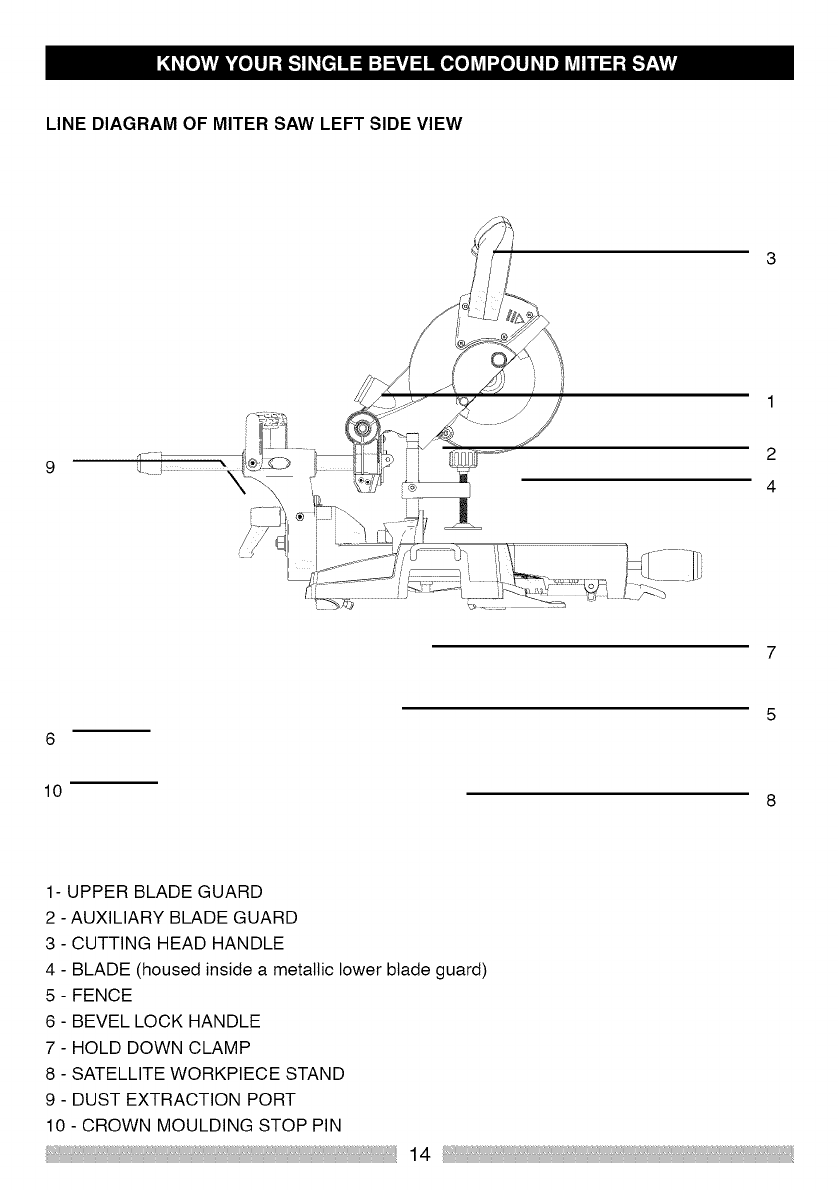
LINE DIAGRAM OF MITER SAW LEFT SIDE VIEW
92
4
6
10
1- UPPER BLADE GUARD
2 - AUXILIARY BLADE GUARD
3 - CUTTING HEAD HANDLE
4 - BLADE (housed inside a metallic bower blade guard)
5 - FENCE
6 - BEVEL LOCK HANDLE
7 - HOLD DOWN CLAMP
8 - SATELLITE WORKPIECE STAND
9 - DUST EXTRACTION PORT
10 - CROWN MOULDING STOP PIN
14
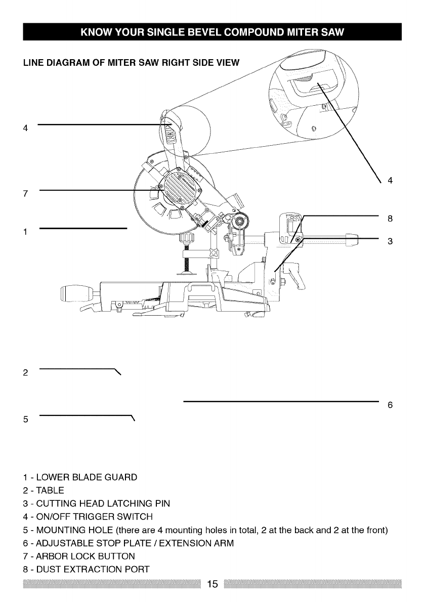
LINE DIAGRAM OF MITER SAW RIGHT SIDE VIEW
4
7
8
3
2 \
1 - LOWER BLADE GUARD
2 - TABLE
3 - CUTTING HEAD LATCHING PIN
4 - ON/OFF TRIGGER SWITCH
5 - MOUNTING HOLE (there are 4 mounting holes in total, 2 at the back and 2 at the front)
6 - ADJUSTABLE STOP PLATE /EXTENSION ARM
7 - ARBOR LOCK BUTTON
8 - DUST EXTRACTION PORT
15
AMPERAGE(AMPS)- Ameasureoftheflow
ofelectriccurrent.Higherratingsgenerally
meansthetootissuitedforheavieruse.
ARBOR- Theshaftonwhichthebladeis
mounted.
ARBORLOCK- Allowstheusertokeep
thebladefromrotatingwhiletightening
orlooseningthearborboltduringblade
replacementorremoval.
BASE- Supportsthetable,holds
accessoriesandallowsforworkbench
orlegsetmounting.
BEVELCUT-Ananglecutmadethrough
thefaceoftheworkpiece.
BEVELLOCKINGHANDLE- Locksthe
mitersawatadesiredbevelangle.
BEVELSCALE- Tomeasurethebevel
angleofthesawblade0°to45oleft.
TUNGSTENCARBIDETIPPED(TCT)
- Extremelyhardsteelpieceswithsharp
cuttingedgesfastenedtocuttingtools
suchassawblades.
COMPOUNDCUT- Acombinationofa
miterangleandabevelangle.
CUTTINGHEADLATCHINGPIN- Locks
themitersawintheloweredpositionfor
compactstorageandtransportation.
DOUBLE-INSULATED- A formofelectrical
protectionfeaturingtwoseparateinsulation
systemstohelpprotectagainstelectric
shock.
MITERSCALE- Indicatesthemiterangle
selected0°to45ototherighthandorleft
handside.
EXTENSIONCORD-An electricalcord
usedbetweenpowertoolsandoutletsto
extendthedistancebetweenthetwo.
Themoreamperageyourtoolusesand
thelongerthedistance,thelargerthewire
neededinyourextensioncord.
EYEPROTECTION- Gogglesorspectacles
intendedtoprotectyoueyes.Eyeprotection
shouldmeettherequirementsofANSIZ.87.1
(USA)orCSAZ94.3-M88(CANADA).
FACESHIELD-An impactresistantshield
toprotectyourfacefromchips,sparks,small
debris.Shouldonlybeusedinconjunction
withadditionaleyeprotection.
FENCE- Helpstokeeptheworkpiecefrom
movingduringcuttingoperations.
16
GUARD - Protective device that forms a
barrier between an hazardous object such as
a blade, wheel or cutter and the operator.
HOLD DOWN CLAMP - Secures the
workpiece during cutting operations.
OPERATOR'S MANUAL- Booklet
accompanying your power tool that describes
the hazards and safe operation procedures
and outlines basic tool operation, care and
maintenance.
KERF - The width of a saw cut, determined
by the thickness and set of the blade
KICKBACK - Sudden and unintended
movement of the tool or the workpiece.
It is typically caused by binding or pinching
of the workpiece.
MITER CUT - A miter is a type of joint where
the two parts to be joined are cut at an angle,
and typically the finished joint forms a 90
degree angle.
MOUNTING HOLES - Used to mount the
miter saw to a level stable work surface.
ON/OFF TRIGGER SWITCH - To start the
tool, squeeze the trigger. Release the trigger
to turn the miter saw OFF.
REVOLUTIONS PER MINUTE (RPM) -
The number of turns or rotations completed
by a spinning object in one minute.
SAW BLADE PATH - The area of the
workpiece or table top directly in line with
the travel of the blade or the part of the
workpiece which wilt be cut.
CUTTING HEAD HANDLE - Contains
the trigger switch. The blade is lowered by
pushing down on the handle. The saw wilt
return to its upright position when the handle
is released.
WARNING LABELS - For your own safety
read and understand any labels attached
to the machine.
17
WARNING I
To avoid injury from unexpected starting
or electrical shock, do not plug the
power cord into a power source during
unpacking or assembly. The power cord
must remain unplugged whenever you are
working on the saw.
WARNING I
To avoid injury and/or damage to the saw,
transport or store the miter saw with the
Cutting Head locked in the down position.
Always ensure that the Cutting Head is
released from its locked position before
beginning cutting operations.
CUTTING HEAD
WARNING: To avoid serious injury, NEVER
perform the unlocing or locking procedure
unless the saw is OFF and the blade
stopped.
Unlocking the Cutting Head (Fig. A)
a) With one hand, grasp and gently press
down on the Cutting Head Handle.
b) With your other hand pull out the Latching
Pin from its socket and allow the head to rise
to its upper position.
Note: When the machine is not in use, lock
the Cutting Head in the down position with
the latching pin fully engaged in its socket.
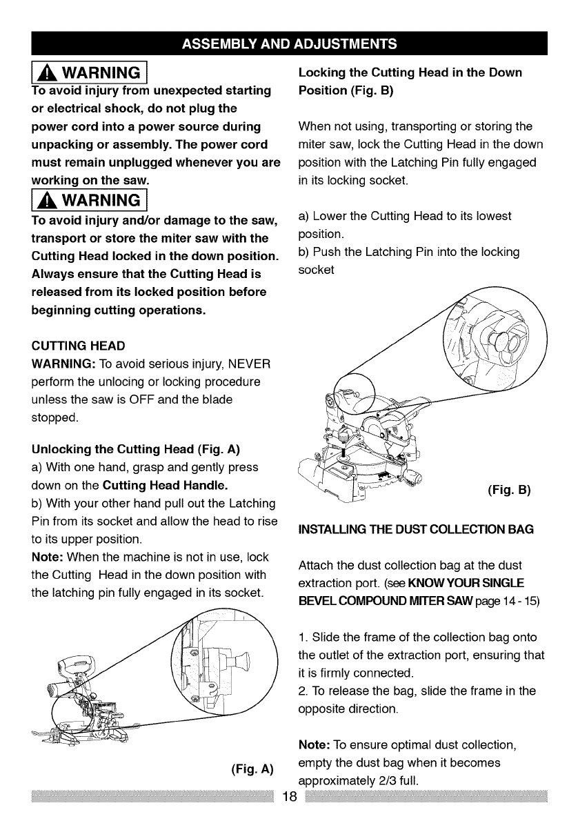
Locking the Cutting Head in the Down
Position (Fig. B)
When not using, transporting or storing the
miter saw, lock the Cutting Head in the down
position with the Latching Pin fully engaged
in its locking socket.
a) Lower the Cutting Head to its lowest
position.
b) Push the Latching Pin into the locking
socket
(Fig. B)
INSTALLING THE DUST COLLECTION BAG
Attach the dust collection bag at the dust
extraction port. (see KNOWYOUR SINGLE
BEVEL COMPOUND MITER SAW page 14- 15)
1. Slide the frame of the collection bag onto
the outlet of the extraction port, ensuring that
it is firmly connected.
2. To release the bag, slide the frame in the
opposite direction.
Note: To ensure optimal dust collection,
(Fig. A) empty the dust bag when it becomes
approximately 2/3 full.
18
CAUTION l
Dispose of the contents of the dust
collection bag in an environmentally
responsible way. It may be neccesary to
wear a dust mask when emptying the dust
collection bag.
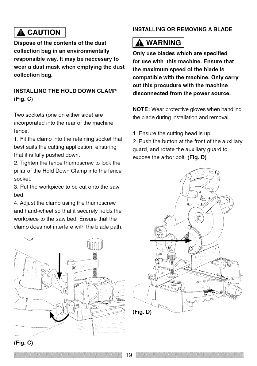
INSTALLING THE HOLD DOWN CLAMP
(Fig. C)
Two sockets (one on either side) are
incorporated into the rear of the machine
fence.
1. Fit the clamp into the retaining socket that
best suits the cutting application, ensuring
that it is fully pushed down.
2. Tighten the fence thumbscrew to lock the
pillar of the Hold Down Clamp into the fence
socket.
3. Put the workpiece to be cut onto the saw
bed.
4. Adjust the clamp using the thumbscrew
and hand-wheel so that it securely holds the
workpiece to the saw bed. Ensure that the
clamp does not interfere with the blade path.
INSTALLING OR REMOVING ABLADE
1_, WARNING I
Only use blades which are specified
for use with this machine. Ensure that
the maximum speed of the blade is
compatible with the machine. Only carry
out this procudure with the machine
disconnected from the power source.
NOTE: Wear protective gloves when handling
the blade during installation and removal.
1. Ensure the cutting head is up.
2. Push the button at the front of the auxiliary
guard, and rotate the auxiliary guard to
expose the arbor bolt. (Fig. D)
(Fig. C)
19
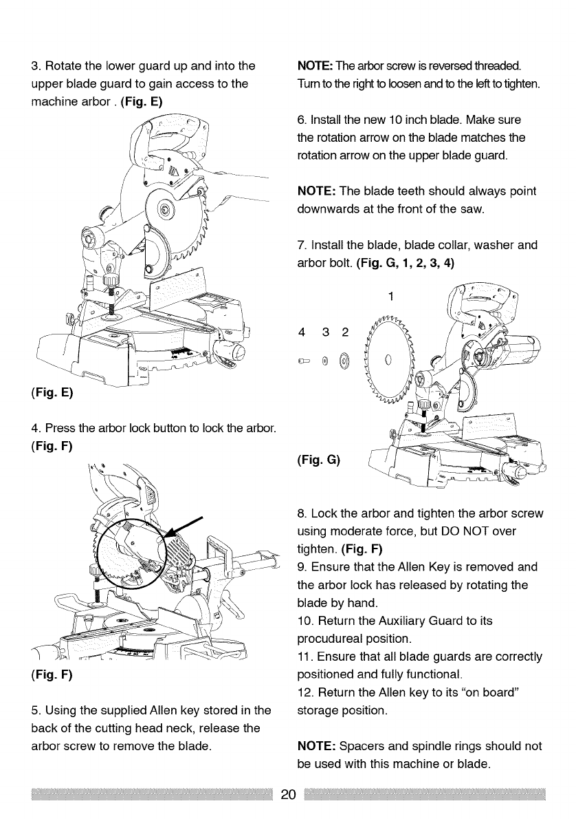
3. Rotate the lower guard up and into the
upper blade guard to gain access to the
machine arbor. (Fig. E)
(Fig. E)
4. Press the arbor lock button to lock the arbor.
(Fig. F)
NOTE: The arbor screw is reversed threaded.
Turn to the right to loosen and to the left to tighten.
6. Install the new 10 inch blade. Make sure
the rotation arrow on the blade matches the
rotation arrow on the upper blade guard.
NOTE: The blade teeth should always point
downwards at the front of the saw.
7. Install the blade, blade collar, washer and
arbor bolt. (Fig. G, 1, 2, 8, 4)
1
4 3 2
(Fig. G)
(Fig. F)
5. Using the supplied Allen key stored in the
back of the cutting head neck, release the
arbor screw to remove the blade.
8. Lock the arbor and tighten the arbor screw
using moderate force, but DO NOT over
tighten. (Fig. F)
9. Ensure that the Allen Key is removed and
the arbor lock has released by rotating the
blade by hand.
10. Return the Auxiliary Guard to its
procudureal position.
11. Ensure that all blade guards are correctly
positioned and fully functional.
12. Return the Allen key to its "on board"
storage position.
NOTE: Spacers and spindle rings should not
be used with this machine or blade.
20
_, WARNING l
Ensure that the blade collars are clean and
correctly positioned on the arbor.
Lower the blade into the table and check for
any contact with the table or table insert.
If contact occurs see CUTTING HEAD
TRAVEL page 25.
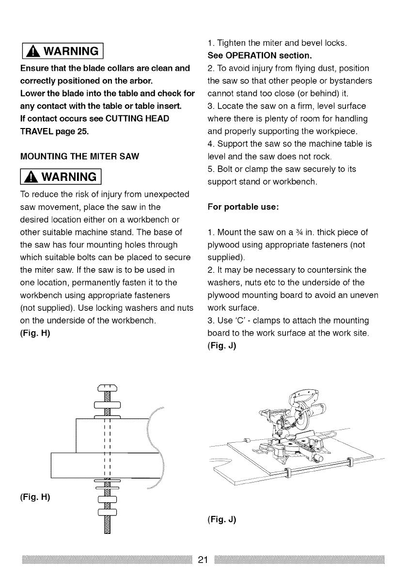
MOUNTING THE MITER SAW
WARNING I
To reduce the risk of injury from unexpected
saw movement, place the saw in the
desired location either on a workbench or
other suitable machine stand. The base of
the saw has four mounting holes through
which suitable bolts can be placed to secure
the miter saw. If the saw is to be used in
one location, permanently fasten it to the
workbench using appropriate fasteners
(not supplied). Use locking washers and nuts
on the underside of the workbench.
(Fig. H)
1. Tighten the miter and bevel locks.
See OPERATION section.
2. To avoid injury from flying dust, position
the saw so that other people or bystanders
cannot stand too close (or behind) it.
3. Locate the saw on a firm, level surface
where there is plenty of room for handling
and properly supporting the workpiece.
4. Support the saw so the machine table is
level and the saw does not rock.
5. Bolt or clamp the saw securely to its
support stand or workbench.
For portable use:
1. Mount the saw on a 3_in. thick piece of
plywood using appropriate fasteners (not
supplied).
2. It may be necessary to countersink the
washers, nuts etc to the underside of the
plywood mounting board to avoid an uneven
work surface.
3. Use 'C' - clamps to attach the mounting
board to the work surface at the work site.
(Fig. J)
(Fig. H)
IIi!ii_
I I
I I
I I
I I
I I
I I
I I
(Fig. J)
21
ADJUSTMENT INSTRUCTIONS
WARNING l
To avoid injury from electric shock or
from an accidental start, make sure the
switch is in the OFF position and the plug
is not connected a power source outlet.
NOTE: When checking angular
alignments the Cutting Head should be
lowered and locked in the down position
with the latching pin fully located in its
socket.
Refer to 'Locking the Cutting Head in the
down position' page 18
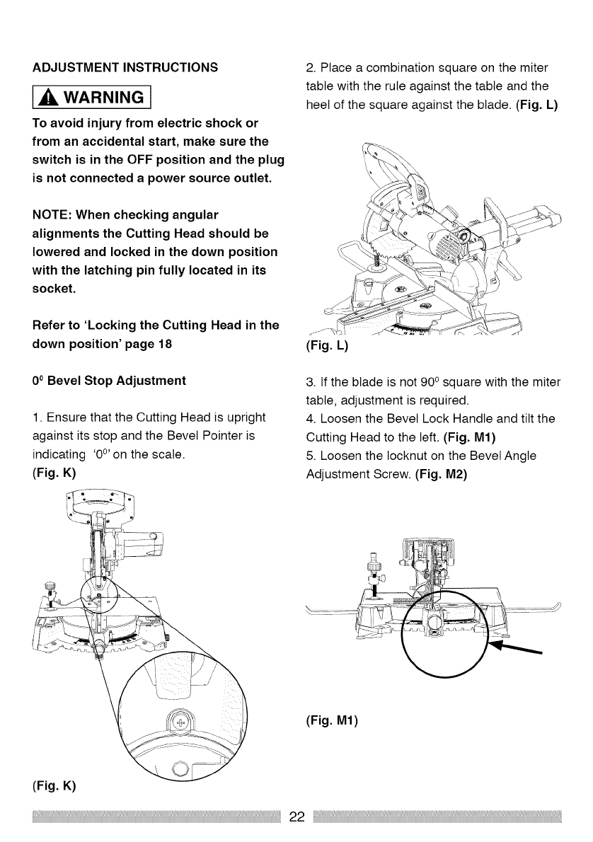
0° Bevel Stop Adjustment
1. Ensure that the Cutting Head is upright
against its stop and the Bevel Pointer is
indicating '0°' on the scale.
(Fig. K)
2. Place a combination square on the miter
table with the rule against the table and the
heel of the square against the blade. (Fig. L)
(Fig. L)
3. If the blade is not 900 square with the miter
table, adjustment is required.
4. Loosen the Bevel Lock Handle and tilt the
Cutting Head to the left. (Fig. M1)
5. Loosen the tocknut on the Bevel Angle
Adjustment Screw. (Fig. M2)
(Fig. M1)
(Fig. K)
22
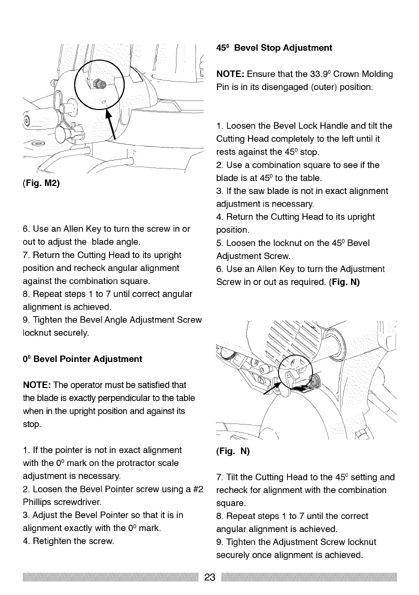
(Fig. M2)
450 Bevel Stop Adjustment
NOTE: Ensure that the 33.90 Crown Molding
Pin is in its disengaged (outer) position.
6. Use an Allen Key to turn the screw in or
out to adjust the blade angle.
7. Return the Cutting Head to its upright
position and recheck angular alignment
against the combination square.
8. Repeat steps 1 to 7 until correct angular
alignment is achieved.
9. Tighten the Bevel Angle Adjustment Screw
Iocknut securely.
1. Loosen the Bevel Lock Handle and tilt the
Cutting Head completely to the left until it
rests against the 450 stop.
2. Use a combination square to see if the
blade is at 450 to the table.
3. If the saw blade is not in exact alignment
adjustment is necessary.
4. Return the Cutting Head to its upright
position.
5. Loosen the Iocknut on the 450 Bevel
Adjustment Screw.
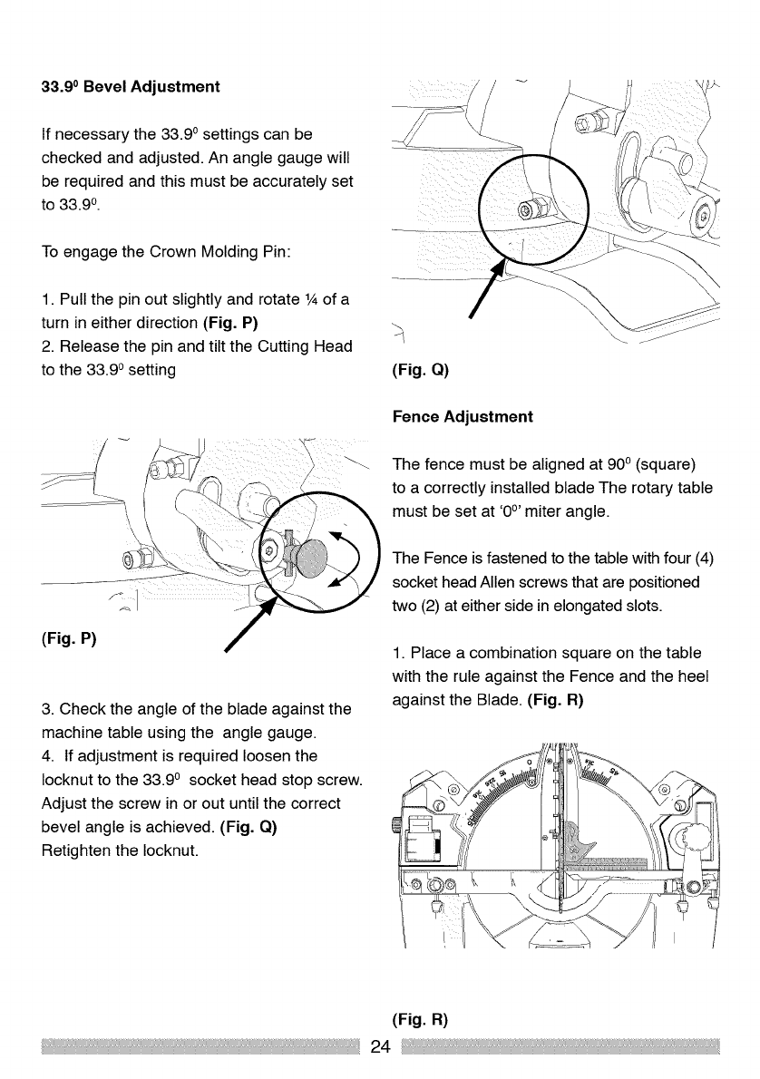
6. Use an Allen Key to turn the Adjustment
Screw in or out as required. (Fig. N)
0°Bevel Pointer Adjustment
NOTE: The operator must be satisfied that
the blade is exactly perpendicular to the table
when in the upright position and against its
stop.
1. If the pointer is not in exact alignment
with the 0° mark on the protractor scale
adjustment is necessary.
2. Loosen the Bevel Pointer screw using a #2
Phillips screwdriver.
3. Adjust the Bevel Pointer so that it is in
alignment exactly with the 0° mark.
4. Retighten the screw.
(Fig. N)
7. Tilt the Cutting Head to the 45osetting and
recheck for alignment with the combination
square.
8. Repeat steps 1 to 7 until the correct
angular alignment is achieved.
9. Tighten the Adjustment Screw Iocknut
securely once alignment is achieved.
23
33.9 oBevel Adjustment
If necessary the 33.9 osettings can be
checked and adjusted. An angle gauge will
be required and this must be accurately set
to 33.90.
To engage the Crown Molding Pin:
1. Pull the pin out slightly and rotate 1Aof a
turn in either direction (Fig. P)
2. Release the pin and tilt the Cutting Head
to the 33.90 setting
(Fig. P)
3. Check the angle of the blade against the
machine table using the angle gauge.
4. If adjustment is required loosen the
Iocknut to the 33.9 o socket head stop screw.
Adjust the screw in or out until the correct
bevel angle is achieved. (Fig. Q)
Retighten the Iocknut.
(Fig. Q)
Fence Adjustment
The fence must be aligned at 90o (square)
to a correctly installed blade The rotary table
must be set at '0°' miter angle.
The Fence is fastened to the table with four (4)
socket head Allen screws that are positioned
two (2) at either side in elongated slots.
1. Place a combination square on the table
with the rule against the Fence and the heel
against the Blade. (Fig. R)
(Fig. R)
24
2. If adjustment is necessary, loosen the four
(4) Fence adjustment screws using an Allen
Key. (Adjustment allen key, supplied)
3. Re-position the Fence in its elongated
slots until alignment is achieved.
4. Securely tighten the socket head screws.
WARNING I
When all angular adjustments have been
successfully completed, the procudure of
the lower blade guard must be checked to
ensure that it is working correctly.
The saw must not be used if the lower
blade guard is not operating correctly.
Miter Angle Pointer Adjustment
NOTE: There are dual miter angle scales
cast into the front of the machine base. A
small pointer indicates the angle selected.
Set the rotary table to 0° Miter ensuring that
the 0° Positive Stop is engaged. Check that
the Miter pointer is in exact alignment with
the 0° index mark.
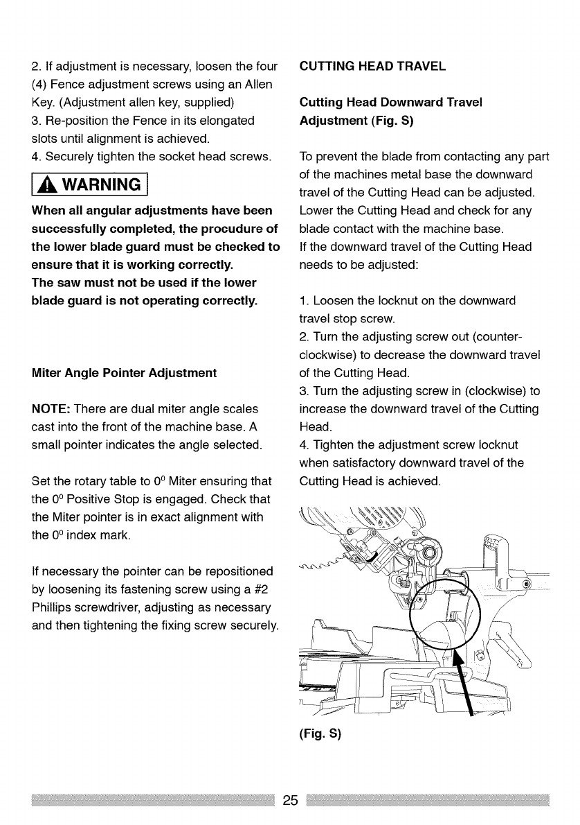
CUTTING HEAD TRAVEL
Cutting Head Downward Travel
Adjustment (Fig. S)
To prevent the blade from contacting any part
of the machines metal base the downward
travel of the Cutting Head can be adjusted.
Lower the Cutting Head and check for any
blade contact with the machine base.
If the downward travel of the Cutting Head
needs to be adjusted:
1. Loosen the Iocknut on the downward
travel stop screw.
2. Turn the adjusting screw out (counter-
clockwise) to decrease the downward travel
of the Cutting Head.
3. Turn the adjusting screw in (clockwise) to
increase the downward travel of the Cutting
Head.
4. Tighten the adjustment screw Iocknut
when satisfactory downward travel of the
Cutting Head is achieved.
If necessary the pointer can be repositioned
by loosening its fastening screw using a #2
Phillips screwdriver, adjusting as necessary
and then tightening the fixing screw securely.
(Fig. S)
25
SAFETY INSTRUCTIONS FOR BASIC SAW
OPERATION
BEFORE USING THE MITER SAW
[,_ WARNING 1
To avoid mistakes that could cause
serious, permanent injury, do not plug the
machine in until the following steps are
com pleted:
Completely assemble and adjust
the saw, following the instructions.
(ASSEMBLY AND ADJUSTMENTS)
Learn the use and function of the ON/
OFF trigger switch, Lower Blade Guard
Release Lever, Upper and Lower Blade
Guards, Bevel Lock Handle and Cutting
Head latching pin.
Review and understand all safety
instructions and operating procedures in
this Operator's Manual.
Review the MAINTENANCE and
TROUBLESHOOTING GUIDE for your
miter saw.
To avoid injury or possible death from
electrical shock:
Make sure that your fingers do not
touch the plug's metal prongs when
plugging or unplugging your miter saw.
(ELECTRICAL REQUIREMENTS AND
SAFETY)
BEFORE EACH USE INSPECT YOUR SAW
Disconnect the miter saw.
To avoid injury from accidental starting,
unplug the saw before any adjustments,
including set-up and blade changes.
Compare the direction of rotation arrow on
the guard to the directionarrow onthe blade.
The blade teeth should always point
downwards at the front of the saw.
Tighten the arbor bolt.
Check for damaged parts. Check for:
Cracks in the blade, and for broken,
chipped or missing blade teeth.
Alignment of moving parts.
Damaged power cords.
Binding of moving parts.
Mounting holes.
Procudure of the Lower Blade Guard:
Push the Cutting Head all the way
down, and then let it rise to until it
stops. The Lower Blade Guard should
fully close enclosing the blade. Follow
instructions inTROUBLESHOOTING
GUIDE for adjustment if necessary.
Any other conditions which may affect
the way your miter saw works.
Keep all guards in place, in working
order and proper adjustment. If any
part of your miter saw is missing, bent,
damaged or broken in any way, or any
electrical parts do not work, turn the saw
OFF and unplug it.
Replace bent, damaged, missing or
defective parts before using the saw
again.
Maintain tools with care. Keep the
miter saw clean for best and safest
performance. Follow instructions for
lubricating. Do not put lubricants on the
blade while it is spinning.
Remove any adjusting tools from the
saw before turning it ON.
To avoid injury from jams, slips or
thrown pieces, use only recommended
accessories.
Check the dust bag before you start
work. Empty the bag if it is more than
half-full.
26
AVAILABLE ACCESSORIES
Consult the ACCESSORIES and
ATTACHMENTS section of this
Operator's Manual for the available
accessories. Follow the instructions that
come with the accessory. The use of
improper accessories may cause risk of
injury to persons.
Choose the correct 10 in. diameter blade
for the material and the type of cutting
you plan to do. Do not use thin kerf
blades.
Make sure the blade is sharp,
undamaged and properly installed. With
the saw unplugged push the Cutting
Head all the way down. Manually spin
the blade and check for clearance. Tilt
the Cutting Head to a 450 bevel angle
and repeat the test.
Make sure that blade and arbor collars
are clean.
Make sure all clamps and locking
screws are tight and that there is no
excessive play in any parts.
KEEP YOUR WORK AREA CLEAN
[_. WARNING I
Cluttered areas and benches invite
accidents.To avoid burns or other fire
damage, never use the miter saw near
flammable liquids, vapors or gases.
Plan ahead to protect your eyes, hands,
face and ears.
Know your miter saw. Read and
understand this Operator's Manual and
the labels affixed to the tool. Learn its
application and limitations as well as the
specific potential hazards peculiar to
this toot. To avoid injury from accidental
contact with moving parts, do not do
layout, assembly or setup work on the
miter saw while any parts are moving.
To avoid accidental starting, make sure
that the trigger switch is in the OFF
position before plugging the miter saw
into a power supply.
PLAN YOUR WORK
Use the right tool. Do not force a tool
or attachment to do a job it was not
designed to do. Use a different tool for
any workpiece that cannot be held in a
solidly braced, fixed position.
1_, CAUTION j
This machine is not designed for cutting
masonry products or products containing
asbestos type materials. Use this miter
saw to cut wood, and wooden based
products. Other materials may shatter,
bind the blade, or create other hazards.
Inspect the workpiece for any prohibited
materials before you begin cutting.
Remove any nails, screws or other such
foreign objects before you start cutting.
DRESS FOR SAFETY
Ony power tool can throw
foreign objects into the eyes.
This can result in permanent
eye damage. Everyday eyeglasses have
only impact resistant lenses and are not
safety glasses. Glasses or goggles not in
compliance with ANSI Z87.1 could seriously
injure you when they break.
27
Do not wear loose clothing, gloves,
neckties or jewelry (rings, watches etc).
They can get caught and draw you into
moving parts.
Wear non-slip footwear.
Tie back long hair.
Roll long sleeves above the elbow.
Noise levels vary widely. To avoid
possible hearing damage, wear hearing
protection when using any miter saw
For dusty procudures, wear a dust mask
along with safety goggles.
INSPECT THE WORKPIECE
Check the workpiece and ensure that it does
not contain prohibited materials such as
masonry or asbestos. Plan the sequence of
procudures you wish to perform to ensure
that the workpiece is always securely
clamped to the saw table. Avoid small pieces
as they are difficult to clamp securely.
Avoid awkward procudures and hand positions
where an inadvertent slip could cause your
fingers or hand to move into the blade.
[,& WARNING l
DO NOT OVER-REACH
To avoid serious blade cut injury, NEVER
extend your arm or hand so that it is in the
path of the blade.
Keep good footing and balance. Stand to one
side so that your face and body are out of
line of a possible kickback. NEVER extend
your arm or hand so that it is "in-line" with the
cutting path of the blade.Freehand cutting is
a major cause of accidents and should not
be attempted.
Ensure that the workpiece is always
firmly resting against the fence, and
where practical is clamped with the hold
down clamp to the table.
The table should be clean and free from
sawdust etc. before the workpiece is
clamped into position.
Ensure that the 'cut-off' material is free to
move sideways away from the blade when
the cut is completed. Ensure that the 'cut-
off' piece cannot become 'jammed' in any
other part of the machine.
Always secure the workpiece. Use hold
down clamp(s) whenever practical.
Do not use this saw to cut small pieces.
If the workpiece being cut would cause
your hand or fingers to be within 6-3/8
in. of the saw blade, the workpiece is too
small.
Keep hands and fingers out of the 'no
hands zone' marked on the saw table by
pictograms
USE EXTRA CAUTION WITH LARGE OR
ODD SHAPED WORKPIECES
Use extra supports such as sawhorses
or roller stands etc, adjusted so they are
at the same height as the saw table, to
prevent large workpieces from tipping or
twisting when being cut.
Never employ another person to hold
or support a large or odd shaped
workpiece, or to help feed the material
into the saw.
When cutting odd shaped workpieces,
plan the sequence of procudures to
ensure the chance of blade binding or
kickback is minimized.
Properly support round or tubular
material so that it can be securely
clamped to the saw table. Use a Hold
Down clamp which is designed to hold
such material.
28
WARNING I
Do not allow familiarity from frequent use
of your miter saw to result in a careless
mistake. A careless fraction of a second is
enough to cause a severe injury.
Before cutting, if the saw makes an
unfamiliar noise or vibrates, stop
immediately. Turn the saw OFF. Unplug the
saw. Do not restart procudures until any
problem has been found and corrected.
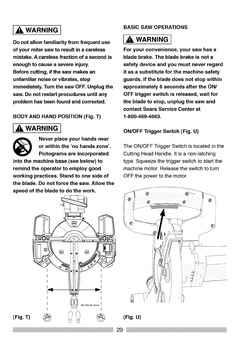
BODY AND HAND POSITION (Fig. T)
WARNING I
Never placeyour hands near
or within the 'no hands zone'.
Pictograms are incorporated
into the machine base (see below) to
remind the operator to employ good
working practices. Stand to one side of
the blade. Do not force the saw. Allow the
speed of the blade to do the work.
BASIC SAW OPERATIONS
I_ WARNING I
For your convenience, your saw has a
blade brake. The blade brake is not a
safety device and you must never regard
it as a substitute for the machine safety
guards. If the blade does not stop within
approximately 6 seconds after the ON/
OFF trigger switch is released, wait for
the blade to stop, unplug the saw and
contact Sears Service Center at
1-800-469-4663.
ON/OFF Trigger Switch (Fig. U)
The ON/OFF Trigger Switch is located in the
Cutting Head Handle. It is a non-latching
type. Squeeze the trigger switch to start the
machine motor. Release the switch to turn
OFF the power to the motor.
("i
(Fig. T) _ i_i _ _ (Fig. U)
29
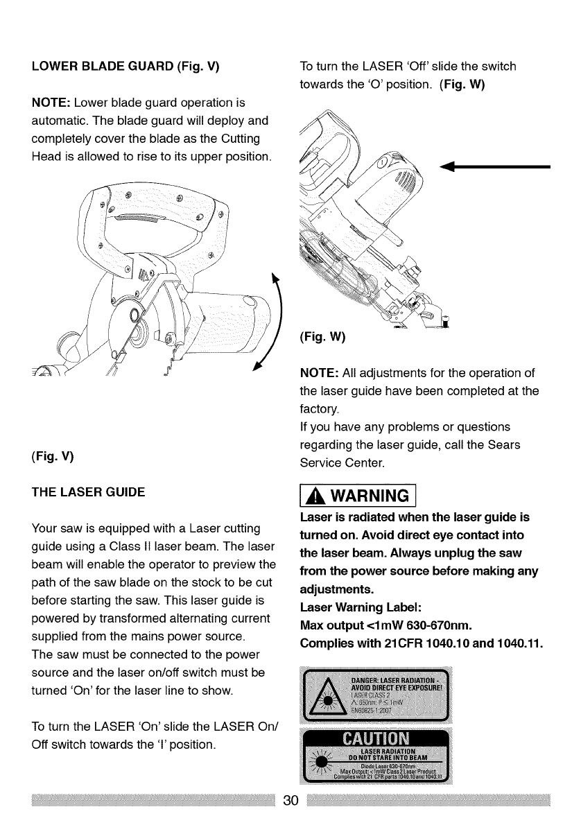
LOWER BLADE GUARD (Fig. V)
NOTE: Lower blade guard operation is
automatic. The blade guard will deploy and
completely cover the blade as the Cutting
Head is allowed to rise to its upper position.
To turn the LASER 'Off' slide the switch
towards the 'O' position. (Fig. W)
(Fig. W)
(Fig. V)
THE LASER GUIDE
Your saw is equipped with a Laser cutting
guide using a Class 11laser beam. The laser
beam will enable the operator to preview the
path of the saw blade on the stock to be cut
before starting the saw. This laser guide is
powered by transformed alternating current
supplied from the mains power source.
The saw must be connected to the power
source and the laser on/off switch must be
turned 'On' for the laser line to show.
NOTE: All adjustments for the operation of
the laser guide have been completed at the
factory.
If you have any problems or questions
regarding the laser guide, call the Sears
Service Center.
IA WARNING I
Laser is radiated when the laser guide is
turned on. Avoid direct eye contact into
the laser beam. Always unplug the saw
from the power source before making any
adjustments.
Laser Warning Label:
Max output <1 mW 630-670nm.
Complies with 21CFR 1040.10 and 1040.11.
To turn the LASER 'On' slide the LASER On/
Off switch towards the '1'position.
30
,A WARNING [
The use of optical instruments with this
laser could increase the eye risk hazard.
Do not attempt to repair or disassemble
the laser. Entrust any repairs required to
a Sears Service Center.
Use the Laser only as specified in this
Instruction Manual. Use of the laser in
any way not specified in this instruction
manual could result in hazardous
radiation exposure.
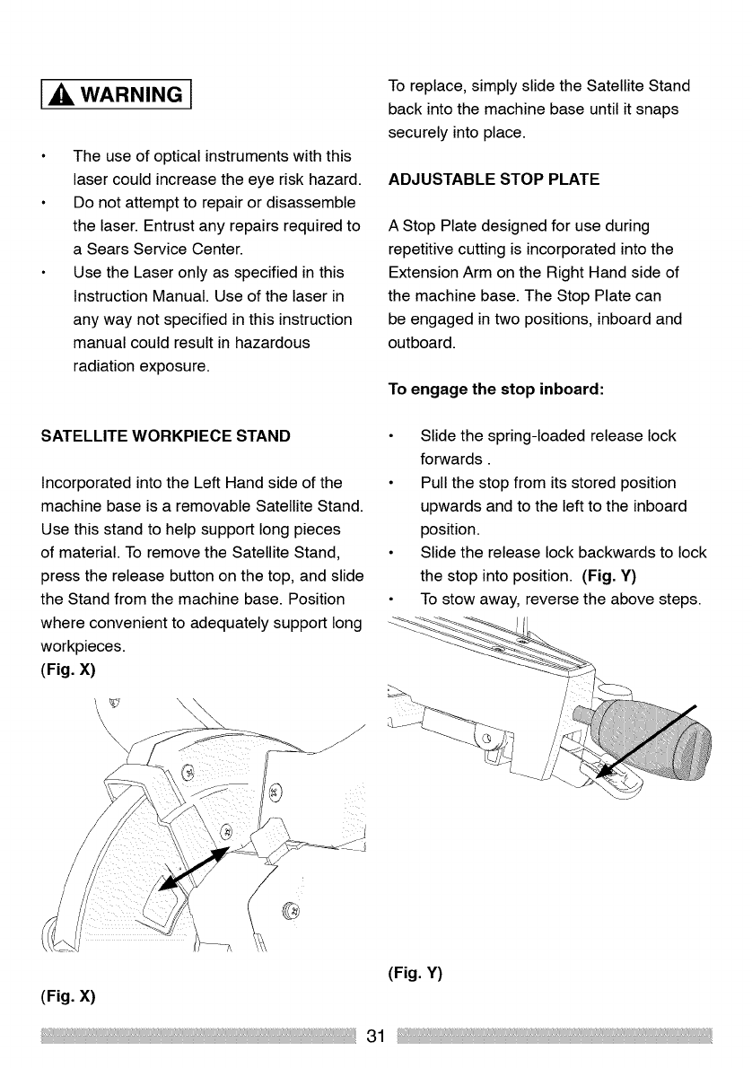
SATELLITE WORKPIECE STAND
Incorporated into the Left Hand side of the
machine base is a removable Satellite Stand.
Use this stand to help support long pieces
of material. To remove the Satellite Stand,
press the release button on the top, and slide
the Stand from the machine base. Position
where convenient to adequately support long
workpieces.
(Fig. X)
\
To replace, simply slide the Satellite Stand
back into the machine base until it snaps
securely into place.
ADJUSTABLE STOP PLATE
A Stop Plate designed for use during
repetitive cutting is incorporated into the
Extension Arm on the Right Hand side of
the machine base. The Stop Plate can
be engaged in two positions, inboard and
outboard.
To engage the stop inboard:
Slide the spring-loaded release lock
forwards.
Pull the stop from its stored position
upwards and to the left to the inboard
position.
Slide the release lock backwards to lock
the stop into position. (Fig. Y)
To stow away, reverse the above steps.
(Fig. Y)
(Fig. X)
31
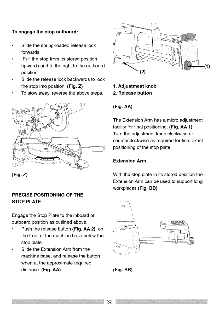
To engage the stop outboard:
Slide the spring-loaded release lock
forwards.
Pull the stop from its stored position
upwards and to the right to the outboard
position.
Slide the release lock backwards to lock
the stop into position. (Fig. Z)
To stow away, reverse the above steps.
(Fig. Z)
PRECISE POSITIONING OF THE
STOP PLATE
Engage the Stop Plate to the inboard or
outboard position as outlined above.
Push the release button (Fig. AA 2) on
the front of the machine base below the
stop plate.
Slide the Extension Arm from the
machine base, and release the button
when at the approximate required
distance. (Fig. AA)
\
(2)
1. Adjustment knob
2. Release button
(Fig. AA)
The Extension Arm has a micro adjustment
facility for final positioning. (Fig. AA 1)
Turn the adjustment knob clockwise or
counterclockwise as required for final exact
positioning of the stop plate.
Extension Arm
With the stop plate in its stored position the
Extension Arm can be used to support long
workpieces (Fig. BB)
o\
(Fig. BB)
32
To adjust the Extension Arm.
Push the release button on the front of
the machine base below the stop plate.
Slide the Extension Arm from the
machine base, and release the button
when at the required distance.
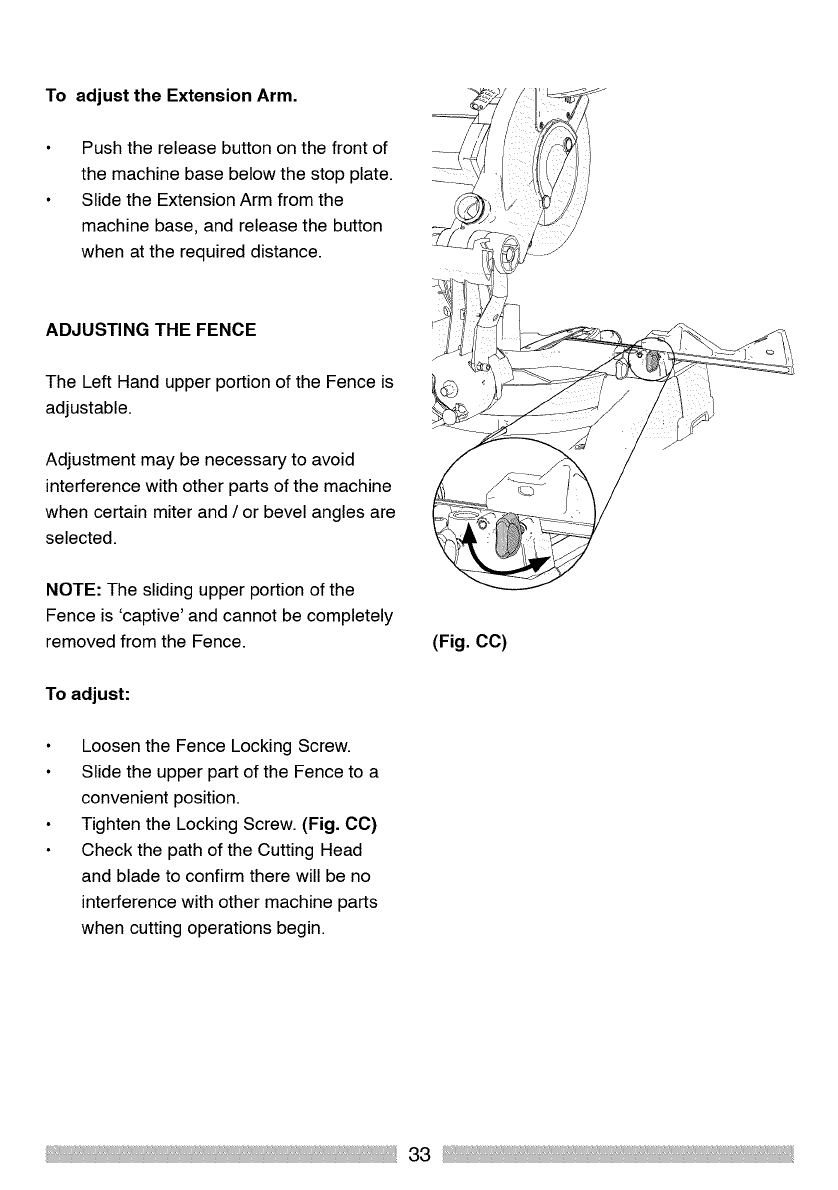
ADJUSTING THE FENCE
The Left Hand upper portion of the Fence is
adjustable.
Adjustment may be necessary to avoid
interference with other parts of the machine
when certain miter and /or bevel angles are
selected.
NOTE: The sliding upper portion of the
Fence is 'captive' and cannot be completely
removed from the Fence.
To adjust:
Loosen the Fence Locking Screw.
Slide the upper part of the Fence to a
convenient position.
Tighten the Locking Screw. (Fig. CC)
Check the path of the Cutting Head
and blade to confirm there will be no
interference with other machine parts
when cutting operations begin.
(Fig. CC)
33
MAKING A BASIC CUT
WARNING I
Ensure that the workpiece is securely
clamped to the saw table and against the
fence and in the required position, before
plugging the saw into a power source.
Cut only one piece at a time.
With the power OFF, lower the Cutting
Head toward the workpiece to observe
the path of the blade.
Also switch on the laser to preview the
path of the blade.
With the Cutting Head in its upper
position, squeeze the trigger switch to
start the motor.
Allow the motor and blade to run up to
full speed.
Gently but firmly lower the Cutting Head
to its lowest position cutting through the
workpiece.
Release the trigger switch and allow the
blade to come to a complete halt.
Raise the Cutting Head to its upper
position with the guard covering the
blade, before removing your hand from
the Cutting Head Handle.
Only remove the workpiece when the
Cutting Head is in the upper position
with the blade guard covering the blade
and the motor stopped.
IA WARNING I
Never leave the saw unattended and
plugged into a power source.
Make the workshop childproof, and always
lock the workshop when not in use.
Store the tool in a secure, locked
cupboard or similar with no access for
unqualified users or children.
MAKING A BASIC MITER CUT
Any angle from 45 oleft to 45 o right is
available, and a dual protractor scale can be
found on the front of the machine base.
Positive stops are located at 0°,150,
22.5°,31.60,450 to the right and to the left.
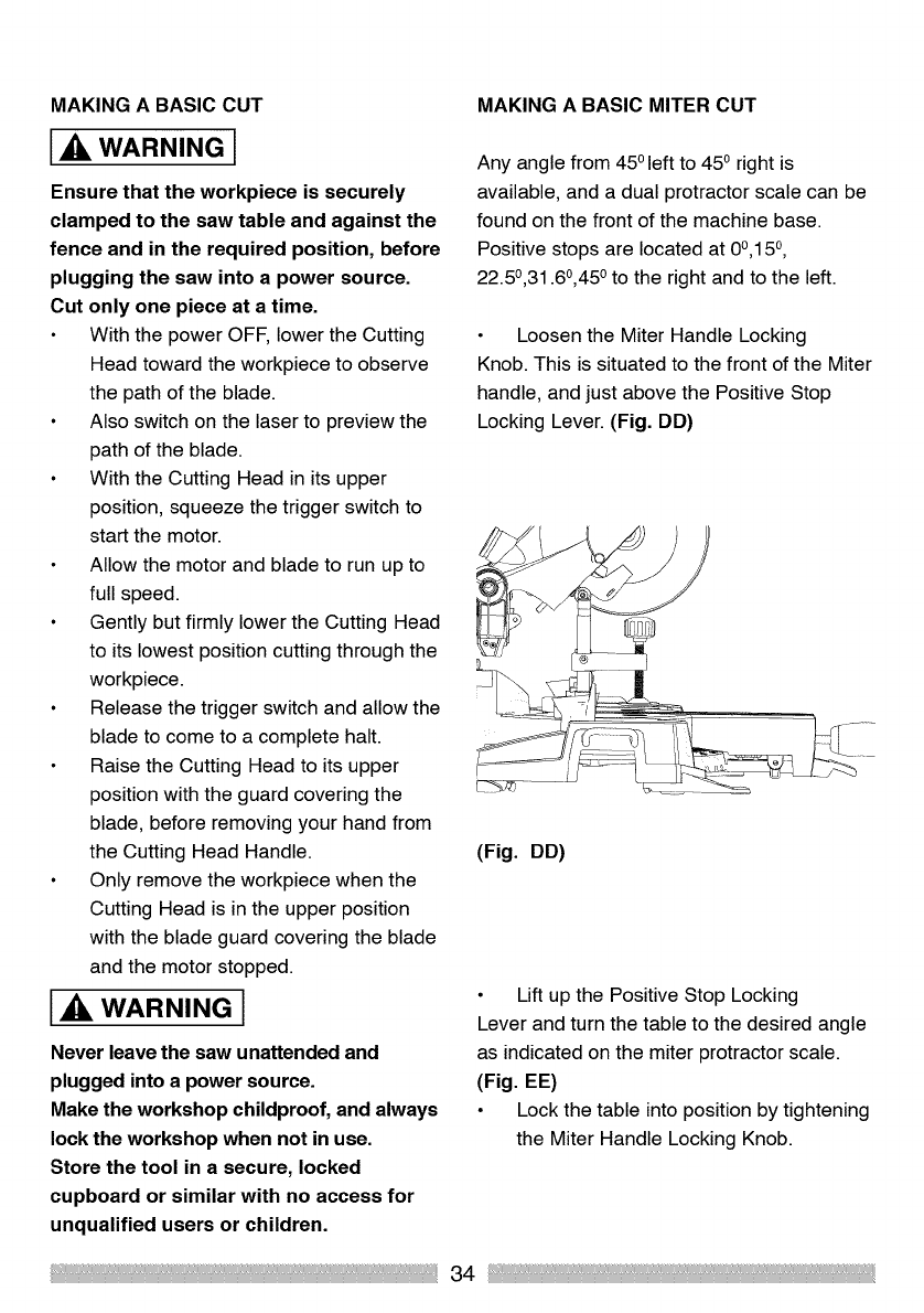
Loosen the Miter Handle Locking
Knob. This is situated to the front of the Miter
handle, and just above the Positive Stop
Locking Lever. (Fig. DD)
(Fig. DD)
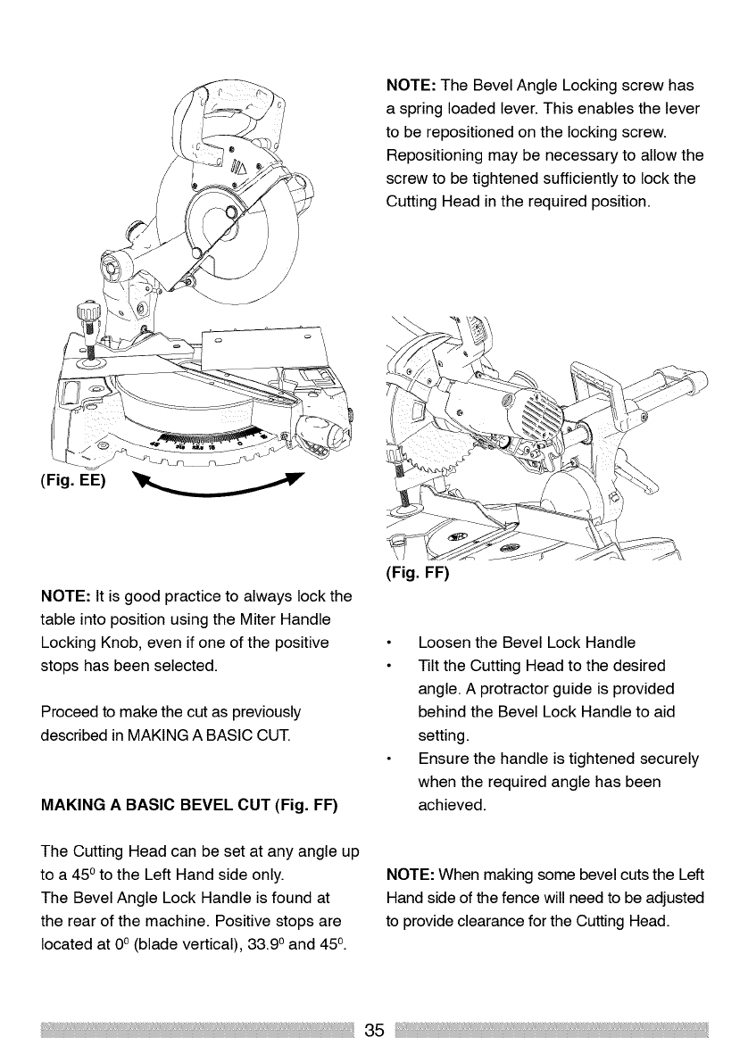
Lift up the Positive Stop Locking
Lever and turn the table to the desired angle
as indicated on the miter protractor scale.
(Fig. EE)
Lock the table into position by tightening
the Miter Handle Locking Knob.
34
NOTE: The Bevel Angle Locking screw has
a spring loaded lever. This enables the lever
to be repositioned on the locking screw.
Repositioning may be necessary to allow the
screw to be tightened sufficiently to lock the
Cutting Head in the required position.
(Fig. EE)
NOTE: It is good practice to always lock the
table into position using the Miter Handle
Locking Knob, even if one of the positive
stops has been selected.
Proceed to make the cut as previously
described in MAKING A BASIC CUT.
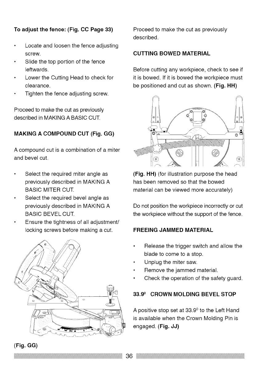
MAKING A BASIC BEVEL CUT (Fig. FF)
(Fig. FF)
Loosen the Bevel Lock Handle
Tilt the Cutting Head to the desired
angle. A protractor guide is provided
behind the Bevel Lock Handle to aid
setting.
Ensure the handle is tightened securely
when the required angle has been
achieved.
The Cutting Head can be set at any angle up
to a 450 to the Left Hand side only.
The Bevel Angle Lock Handle is found at
the rear of the machine. Positive stops are
located at 0° (blade vertical), 33.90 and 45 °.
NOTE: When making some bevel cuts the Left
Hand side of the fence will need to be adjusted
to provide clearance for the Cutting Head.
35
To adjust the fence: (Fig. CC Page 33)
Locate and loosen the fence adjusting
screw.
Slide the top portion of the fence
leftwards.
Lower the Cutting Head to check for
clearance.
Tighten the fence adjusting screw.
Proceed to make the cut as previously
described in MAKING A BASIC CUT.
MAKING A COMPOUND CUT (Fig. GG)
A compound cut is a combination of a miter
and bevel cut.
Select the required miter angle as
previously described in MAKING A
BASIC MITER CUT.
Select the required bevel angle as
previously described in MAKING A
BASIC BEVEL CUT.
Ensure the tightness of all adjustment/
locking screws before making a cut.
Proceed to make the cut as previously
described.
CUTTING BOWED MATERIAL
Before cutting any workpiece, check to see if
it is bowed. If it is bowed the workpiece must
be positioned and cut as shown. (Fig. HH)
(Fig. HH) (for illustration purpose the head
has been removed so that the bowed
material can be viewed more accurately)
Do not position the workpiece incorrectly or cut
the workpiece without the support of the fence.
FREEING JAMMED MATERIAL
Release the trigger switch and allow the
blade to come to a stop.
Unplug the miter saw.
Remove the jammed material.
Check the operation of the safety guard.
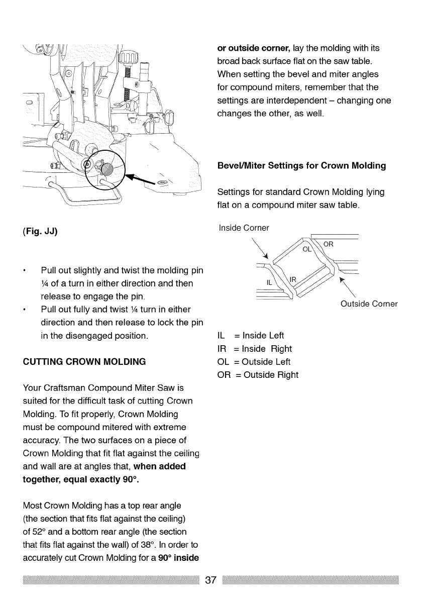
33.90 CROWN MOLDING BEVEL STOP
A positive stop set at 33.90 to the Left Hand
is available when the Crown Molding Pin is
engaged. (Fig. JJ)
(Fig. GG)
36
or outside corner, lay the molding with its
broad back surface flat on the saw table.
When setting the bevel and miter angles
for compound miters, remember that the
settings are interdependent - changing one
changes the other, as well.
\
Bevel/Miter Settings for Crown Molding
\ ....................
(Fig. JJ)
Pull out slightly and twist the molding pin
1Aof a turn in either direction and then
release to engage the pin.
Pull out fully and twist 1Aturn in either
direction and then release to lock the pin
in the disengaged position.
CUTTING CROWN MOLDING
Your Craftsman Compound Miter Saw is
suited for the difficult task of cutting Crown
Molding. To fit properly, Crown Molding
must be compound mitered with extreme
accuracy. The two surfaces on a piece of
Crown Molding that fit flat against the ceiling
and wall are at angles that, when added
together, equal exactly 90 °.
Settings for standard Crown Molding lying
flat on a compound miter saw table.
Inside Corner
\OR
\
Outside Corner
IL = Inside Left
IR = Inside Right
OL = Outside Left
OR = Outside Right
Most Crown Molding has a top rear angle
(the section that fits flat against the ceiling)
of 52° and a bottom rear angle (the section
that fits flat against the wall) of 38°. In order to
accurately cut Crown Molding for a 90°inside
37
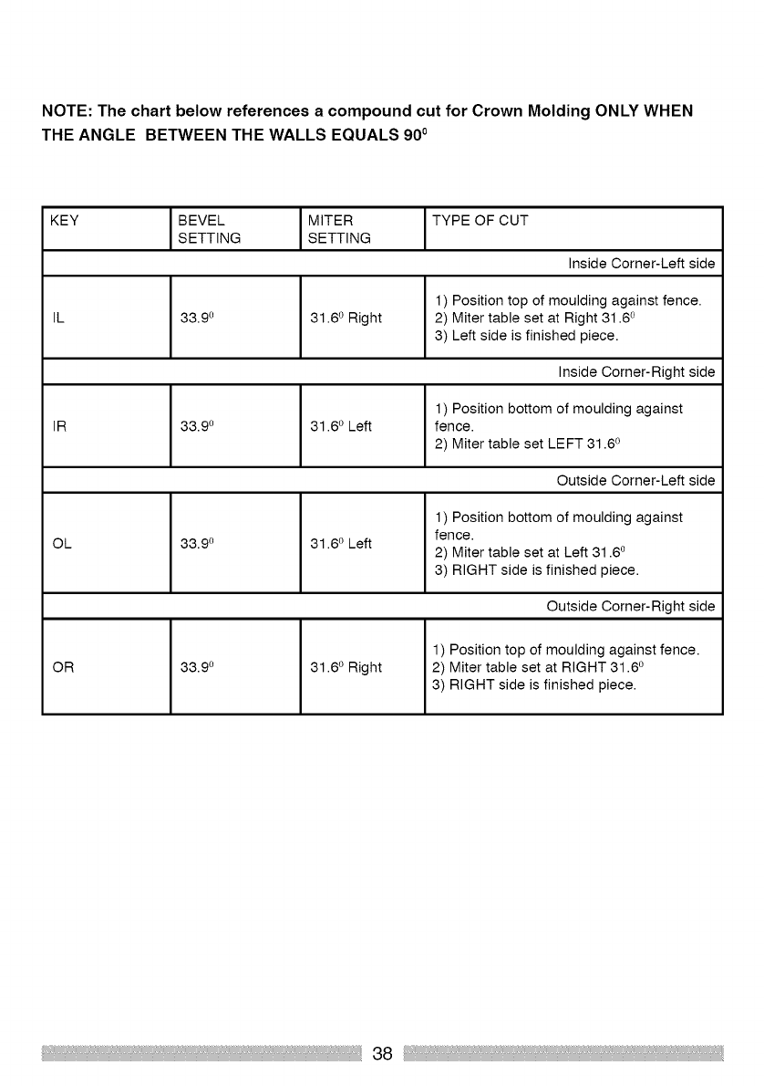
NOTE: The chart below references a compound cut for Crown Molding ONLY WHEN
THE ANGLE BETWEEN THE WALLS EQUALS 900
KEY BEVEL MITER TYPE OF CUT
SETTING SETTING
Inside Corner-Left side
1) Position top of moulding against fence.
IL 33.9 o 31.6 ° Right 2) Miter table set at Right 31.6 °
3) Left side is finished piece.
Inside Corner-Right side
1) Position bottom of moulding against
IR 33.9 o 31.6 o Left fence.
2) Miter table set LEFT 31.6 °
Outside Corner-Left side
OL 33.9 o 31.6 ° Left
1) Position bottom of moulding against
fence.
2) Miter table set at Left 31.6 o
3) RIGHT side is finished piece.
Outside Corner-Right side
1) Position top of moulding against fence.
OR 33.9 o 31.6 ° Right 2) Miter table set at RIGHT 31.6 °
3) RIGHT side is finished piece.
38
[_ DANGER 1
To avoid injury, never put lubricants on
the blade while it is spinning.
[_ WARNING 1
To avoid fire or toxic reaction, never
use gasoline, naphtha, acetone,
lacquer thinner or other similar highly
volatile solvents to clean the miter
saw.
To avoid injury from unexpected
starting or electrical shock, unplug
the power cord before working on the
saw.
For your safety, this saw is double-
insulated. To avoid electrical shock,
fire or injury use only parts identical
to those identified in the schematic
diagram.
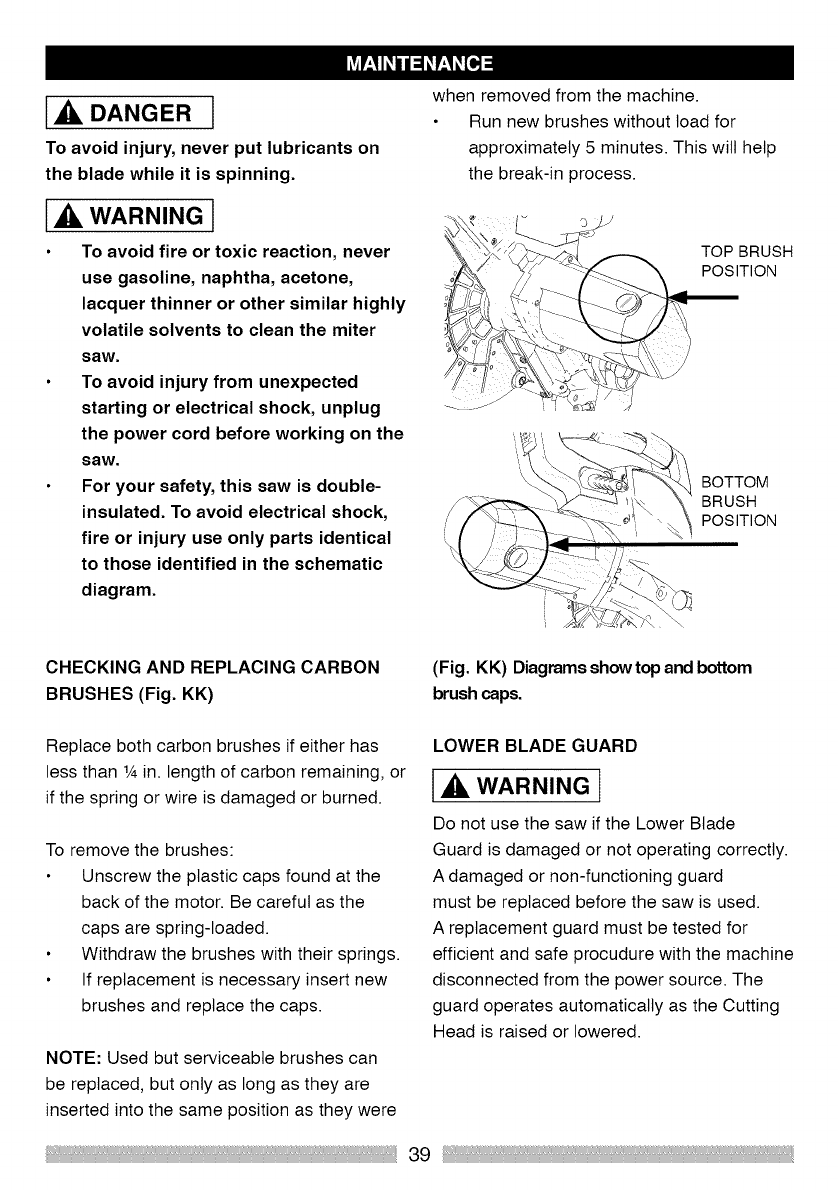
when removed from the machine.
Run new brushes without load for
approximately 5 minutes. This will help
the break-in process.
TOP BRUSH
POSITION
BOTTOM
BRUSH
POSITION
CHECKING AND REPLACING CARBON
BRUSHES (Fig. KK)
(Fig. KK) Diagrams show top and bottom
brush caps.
Replace both carbon brushes if either has
less than 1Ain. length of carbon remaining, or
if the spring or wire is damaged or burned.
To remove the brushes:
Unscrew the plastic caps found at the
back of the motor. Be careful as the
caps are spring-loaded.
Withdraw the brushes with their springs.
If replacement is necessary insert new
brushes and replace the caps.
NOTE: Used but serviceable brushes can
be replaced, but only as long as they are
inserted into the same position as they were
LOWER BLADE GUARD
1,_. WARNING]
Do not use the saw if the Lower Blade
Guard is damaged or not operating correctly.
A damaged or non-functioning guard
must be replaced before the saw is used.
A replacement guard must be tested for
efficient and safe procudure with the machine
disconnected from the power source. The
guard operates automatically as the Cutting
Head is raised or lowered.
39
DUST COLLECTION BAG
To maintain extraction efficiency empty
the Dust Collection Bag when it becomes
approximately 2/3 full. Dispose of the
contents in an environmentally responsible
manner. The bag has a side zip opening.
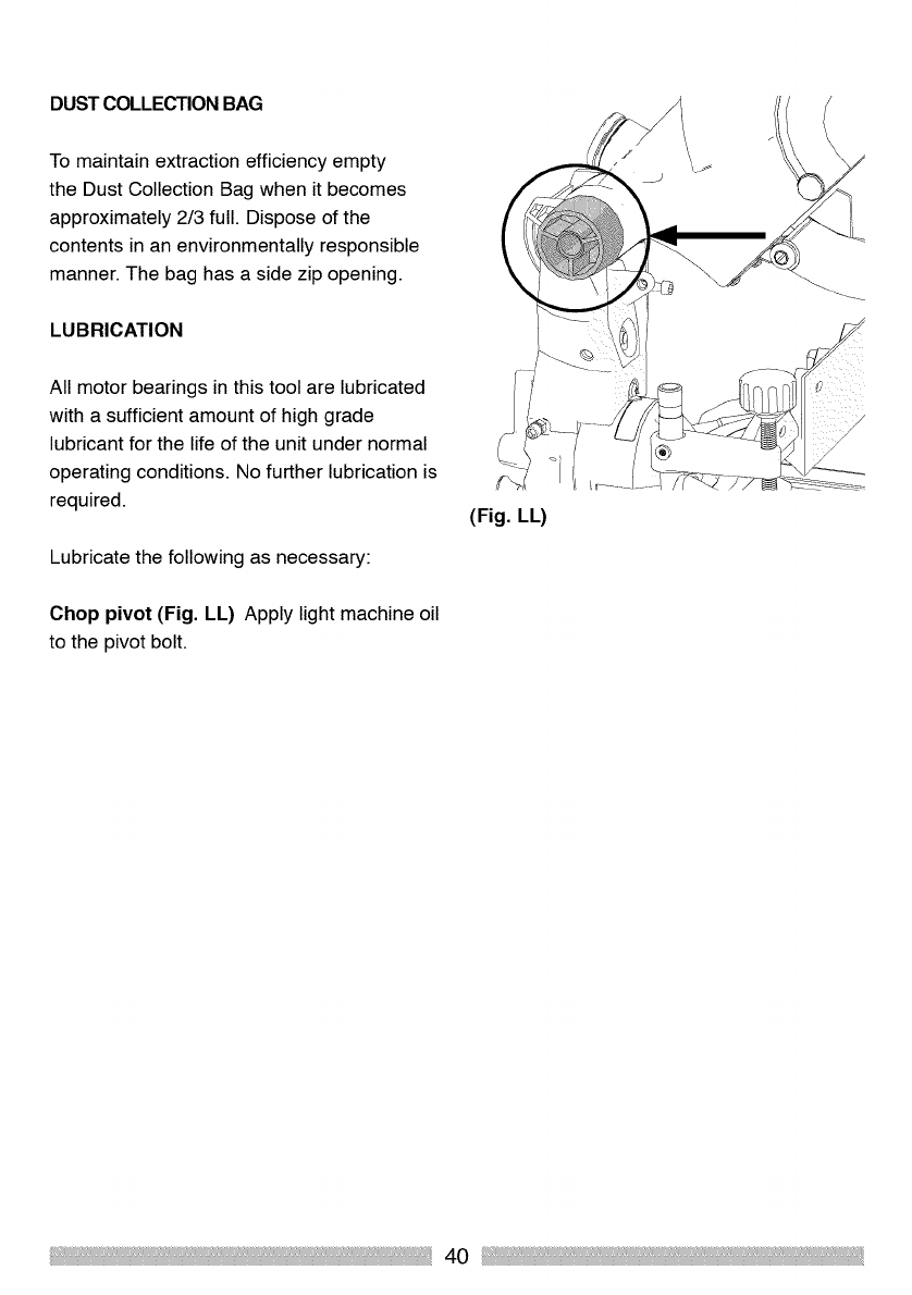
LUBRICATION
All motor bearings in this tool are lubricated
with a sufficient amount of high grade
lubricant for the life of the unit under normal
operating conditions. No further lubrication is
required.
Lubricate the following as necessary:
Chop pivot (Fig. LL) Apply light machine oil
to the pivot bolt.
40
WARNING l
To avoid injury from accidental starting, always turn switch OFF and unplug the
machine before attempting any maintenance or carrying out any adjustments
to your miter saw.
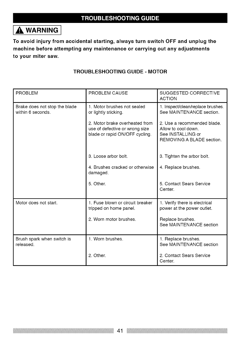
TROUBLESHOOTING GUIDE - MOTOR
PROBLEM PROBLEM CAUSE
Brake does not stop the blade
within 6 seconds.
Motor does not start.
Brush spark when switch is
released.
1. Motor brushes not sealed
or lightly sticking.
2. Motor brake overheated from
use of defective or wrong size
blade or rapid ON/OFF cycling.
3. Loose arbor bolt.
4. Brushes cracked or otherwise
damaged.
5. Other.
1. Fuse blown or circuit breaker
tripped on home panel.
2. Worn motor brushes.
1. Worn brushes.
2. Other.
SUGGESTED CORRECTIVE
ACTION
1. Inspect/clean/replace brushes.
See MAINTENANCE section.
2. Use a recommended blade.
Allow to cool down.
See INSTALLING or
REMOVING A BLADE section.
3. Tighten the arbor bolt.
4. Replace brushes.
5. Contact Sears Service
Center.
1. Verify there is electrical
power at the power outlet.
Replace brushes.
See MAINTENANCE section
1. Replace brushes.
See MAINTENANCE section
2. Contact Sears Service
Center.
41
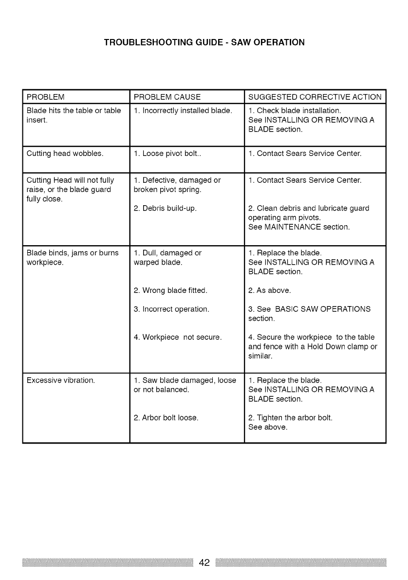
TROUBLESHOOTING GUIDE - SAW OPERATION
PROBLEM PROBLEM CAUSE SUGGESTED CORRECTIVE ACTION
Blade hits the table or table 1. Incorrectly installed blade. 1. Check blade installation.
insert. See INSTALLING OR REMOVING A
BLADE section.
Cutting head wobbles. 1. Loose pivot bolt.. 1. Contact Sears Service Center.
1. Contact Sears Service Center.
1. Defective, damaged or
broken pivot spring.
2. Debris build-up.
Cutting Head will not fully
raise, or the blade guard
fully close.
Blade binds, jams or burns
workpiece.
Excessive vibration.
1. Dull, damaged or
warped blade.
2. Wrong blade fitted.
3. Incorrect operation.
4. Workpiece not secure.
1. Saw blade damaged, loose
or not balanced.
2. Arbor bolt loose.
2. Clean debris and lubricate guard
operating arm pivots.
See MAINTENANCE section.
1. Replace the blade.
See INSTALLING OR REMOVING A
BLADE section.
2. As above.
3. See BASIC SAW OPERATIONS
section.
4. Secure the workpiece to the table
and fence with a Hold Down clamp or
similar.
1. Replace the blade.
See INSTALLING OR REMOVING A
BLADE section.
2. Tighten the arbor bolt.
See above.
42
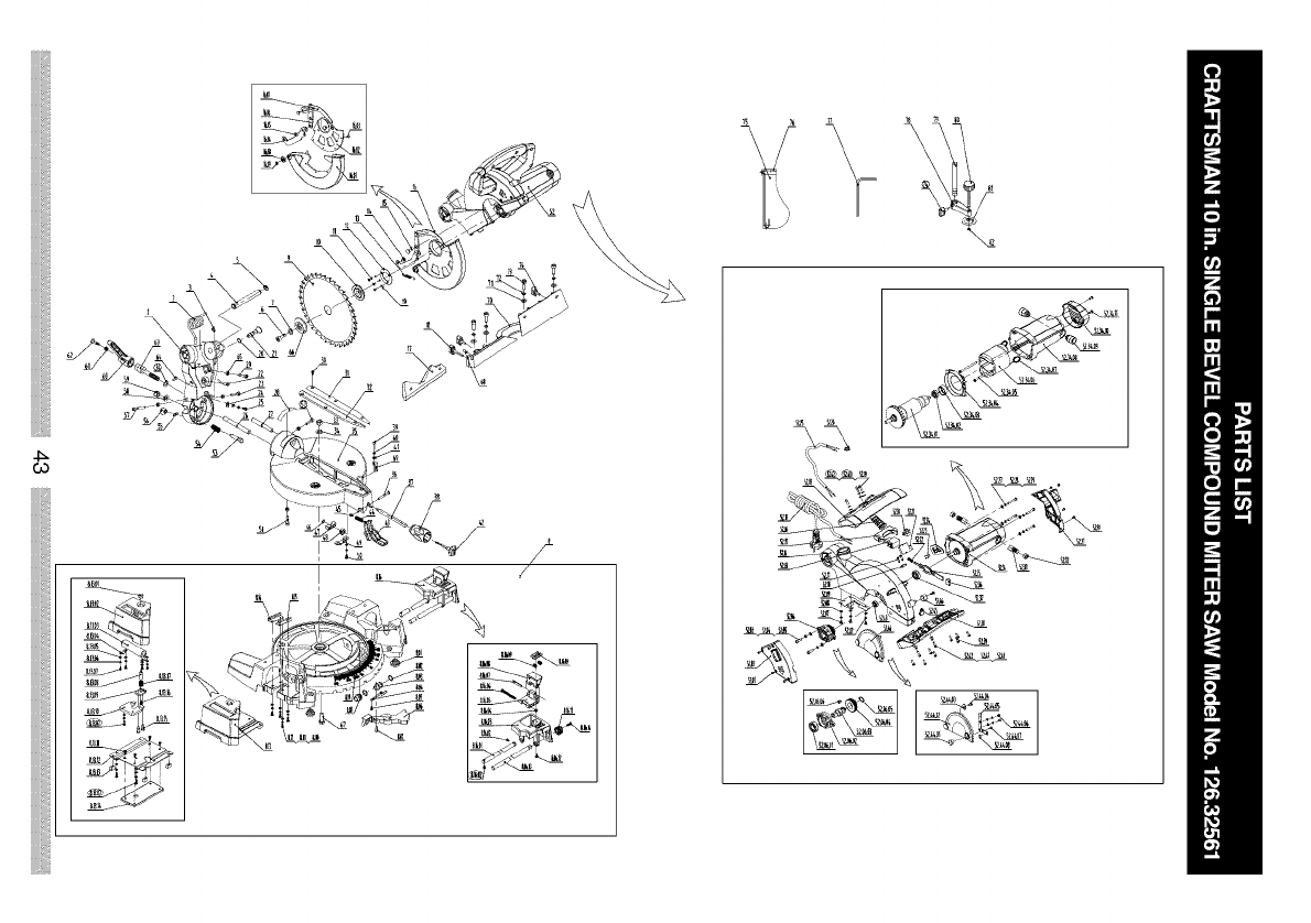

019-0001 Main Assembly 1 8.16.11 019-0143 Knob 1
019-0011 Left side ext ass 1 8.16.12 019-0144 Screw 1
019-0012 Right side ext ass 1 8.16.13 019-0145 Threaded bar 1
019-0013 Motor Assembly 1 8.16.14 019-0113 Screw M4xl0mm 1
1. 019-0101 neck 1 9. 019-0146 Sawblade 1
2. 019-0102 Spring 1 10 019-0147 Inner flange 1
3. 019-0103 Circlip 1 11. 019-0148 Screw M4xl0mm 3
4. 019-0104 Pivot shaft 1 12. 019-0149 Guard ret plate 1
5. 019-0105 Spindle clip 16mm 2 13. 019-0150 Spring 1
6. 019-0106 Screw M8x20mm 1 14. 019-0151 Screw 1
7. 019-0107 Washer 8mm 1 15. 019-0152 Screw 1
8. 019-0108 Base assembly 1 16. 019-0153 Guard assembly 1
8.01 019-0109 Rubberfoot 4 16.01 019-0154 Guard(clear) 1
8.02 019-0110 Spindle clip 18mm 2 16.02 019-0155 Guard (casting) 1
8.03 019-0111 sleeve 1 16.03 019-0156 Rivet 5
8.04 019-0112 Spring 1 16.04 019-0157 Linkage 1
8.05 019-0113 Screw M4xl0mm 1 16.05 019-0158 Rivet 3
8.06 019-0114 Lever 1 16.06 019-0159 Linkage 1
8.07 019-0115 Screw 1 16.07 019-0160 Linkage 1
8.08 019-0116 sleeve 1 16.08 019-0161 Wheel 1
8.09 019-0117 Base 1 16.09 019-0162 Circlip 1
8.10 019-0118 ScrewM4x8mm 4 17. 019-0163 Sliding fence 1
8.11 019-0119 washer 4mm 4 18. 019-0164 Knob 1
8.12 019-0120 Washer 4mm 4 19. 019-0165 Washer 4mm 3
8.13 019-0011 Left side ext ass 1 20. 019-0166 O-ring 6.9x1.8mm 1
8.13.01 019-0122 button 1 21. 019-0167 Head lock Pin 1
8.13.02 019-0123 Left side ext cast 1 22. 019-0168 Laser Unit 1
8.13.03 019-0124 Roller 1 23. 019-0169 Screw M6x25mm 1
8.13.04 019-0125 axle clamp 2 24. 019-0170 Angle indicator 1
8.13.05 019-0120 Washer4mm 11 25. 019-0171 ScrewM6x12mm 1
8.13.06 019-0119 Spring washer 4mm 11 26. 019-0172 Shaft 1
8.13.07 019-0113 Screw M4xl0mm 11 27. 019-0173 Shaft 1
8.13.08 019-0126 Lockpin 1 28. 019-0174 Anglescale 1
8.13.09 019-0127 Plate 1 1 29. 019-0175 Screw M6x35mm 1
8.13.10 019-0128 Slide plate 1 30. 019-0113 Screw M4xl0mm 6
8.13.11 019-0129 ScrewM4x8mm 1 31. 019-0176 Blade throat RHS 1
8.13.12 019-0130 baseplate 1 32. 019-0177 Blade throat LHS 1
8.13.13 019-0131 Rubberfoot 4 33. 019-0178 Locknut M10 1
8.13.14 019-0132 ballast weight 1 34. 019-0179 Washer 10mm 2
8.13.15 019-0133 Screw 2 35. 019-0180 Table 1
8.13.16 019-0129 Screw M4x8mm 1 36. 019-0181 Screw 1
8.13.17 019-0130 Spring 1 37. 019-0182 Screw 1
8.14 019-0131 Slide bott plate 3 1 38. 016-0125 Table angle knob 1
8.15 019-0132 Slidebottplate4 1 39. 019-0183 ScrewM5x16mm 1
8.16 019-0012 Right side ext ass 1 40. 019-0184 Spring washer 5mm 1
8.16.01 019-0134 Extension Rod 1 41. 019-0185 Washer5mm 1
8.16.02 019-0118 ScrewM4x8mm 2 42. 016-0110 Table knobcap 1
8.16.03 019-0135 Right side ext cast 1 43. 019-0186 Table index lever 1
8.16.04 019-0136 LocknutM6 1 44. 019-0187 Spring 1
8.16.05 019-0137 End Stop lower 1 45. 019-0188 Locknut M5 1
8.16.06 019-0138 Screw M6x60mm 1 46. 019-0189 Circlip 1
8.16.07 019-0139 Spring dowel 1 47. 019-0190 Locking block 1
8.16.08 019-0140 End Stop Upper 1 48. 019-0191 Nut M10 1
8.16.09 019-0141 Spring 2 49. 019-0192 Nut retaining plate 1
8.16.10 019-0142 Sliding lock plate 1 50. 019-0113 Screw M4xl0mm 2
44

51. 019-0169 Screw M6x25mm 1
52. 019-0013 Motor assembly 1
52.01 019-0194 Screw M4x6mm 5
52.02 019-0195 Left cover 1
52.03 019-0183 Screw M5x16bb 2
52.04 019-0184 Spring washer 5mm 2
52.05 019-0185 Screw 2
52.06 019-0196 Gear box assembly 1
52.06.01 019-0197 Bearing 6003-2Z 1
52.06.02 019-0198 Gear box cover 1
52.06.03 019-0199 Arbor Shaft 1
52.06.04 019-0200 Gear 1
52.06.05 019-0201 Circlip 20mm 1
52.06.06 019-0202 Key 1
52.07 019-0113 Screw M4xl0mm 3
52.08 019-0120 Washer 4mm 3
52.09 019-0203 Cover 1
52.10 019-0204 Cable clamp 1
52.11 019-0205 screw ST4.2x14mm 2
52.12 019-0119 Spring washer 4mm 3
52.14 019-0207 Blade guard 1
52.15 019-0208 Trigger 1
52.16 019-0209 Cable strain relief 1
52.17 019-0210 Cable 1
52.18 019-0211 Upper Handle 1
52.19 019-0212 Screw M5x14MM 3
52.20 019-0213 Connector 1
52.21 019-0214 Transformer 1
52.22 019-0215 Spring 1
52.23 019-0216 Laser switch 1
52.24 019-0217 Switch cover 1
52.25 019-0218 Laser wire 1
52.26 019-0219 Grommet 2
52.27 019-0185 Washer 5mm 4
52.28 019-0184 Spring washer 5mm 4
52.29 019-0220 Screw M5x3mm 4
52.30 019-0194 Screw M4x6mm 4
52.31 019-0221 Right cover 1
52.32 019-0222 Brush cover 2
52.33 019-0223 Carbon brush 2
52.34 019-0224 Motor assembly 1
52.34.01 019-0225 Rotor 1
52.34.02 019-0226 Bearing 629-2Z 1
52.34.03 019-0227 Bearing mount 1
52.34.04 019-0228 Flow guide 1
52.34.05 019-0229 screw ST4.2x75 4
52.34.06 019-0230 Stator 1
52.34.07 019-0231 Connector 2
52.34.08 019-0232 Motor housing 1
52.34.09 019-0233 Brush holder 2
52.34.10 019-0234 Motor end cap 1
52.34.11 019-0205 screw ST4.2x14 2
52.35 019-0235 Arbor lock 1
52.36 019-0236 Knob 1
52.37 019-0237 Bearing 6001-2RS 1
52.38 019-0238 Handle (Lower) 1
52.39 019-0239 Screw ST4.2x16 8
52.40 019-0212 Screw M5x14 2
52.41 019-0184 Spring washer 5mm 5
52.42 019-0185 Washer 5mm 5
52.43 019-0240 Bearing 699-2Z 1
52.44 019-0241 Arbor cover ass 1
52.44.01 019-0242 Push button 1
52.44.02 019-0243 Cover 1
52.44.03 019-0244 Washer5x18x2 1
52.44.04 019-0245 Screw M5xl0mm 1
52.44.05 019-0246 Spring 1
52.44.06 019-0194 Screw M4x6 2
52.44.07 019-0247 screw ST4.2xl0 1
52.44.08 019-0248 Ball 1
52.45 019-0249 Cover 1
52.46 019-0250 Cover 1
53. 019-0251 Locking pin 33.9 ° 1
54. 019-0252 Spring 1
55. 019-0253 Pin 1
56. 019-0254 Knob 2
57. 019-0255 Screw M6x40 2
58. 019-0256 Washer 12mm 1
59. 019-0257 Locknut M12 1
60. 019-0258 Bevel lock lever 1
61. 019-0259 QSpring 1
62. 019-0260 Screw 1
63. 019-0261 Screw 1
64. 019-0262 Screw M5xl0mm 3
65. 019-0263 Nut M6 4
66. 019-0264 Outer Flange 1
67. 019-0265 Bolt M10x30mm 1
68. 019-0266 Screw M6x16mm 1
69. 019-0267 Angle arrow 1
70. 019-0268 Fence 1
71. 019-0269 Washer 6mm 4
72. 019-0270 Spring washer 6mm 4
73. 019-0271 Screw M6x30mm 4
74. 019-0272 Knob 3
75. 019-0273 Dust collecting bag 1
76. 019-0274 Wire holder 1
77. 019-0275 hexagon key 6mm 1
78. 019-0276 Clamp Body 1
79. 019-0277 Clamp Post 1
80. 019-0278 Clamp Screw 1
81. 019-0279 Clamp Shoe 1
82. 019-0280 Circlip 1
45

46
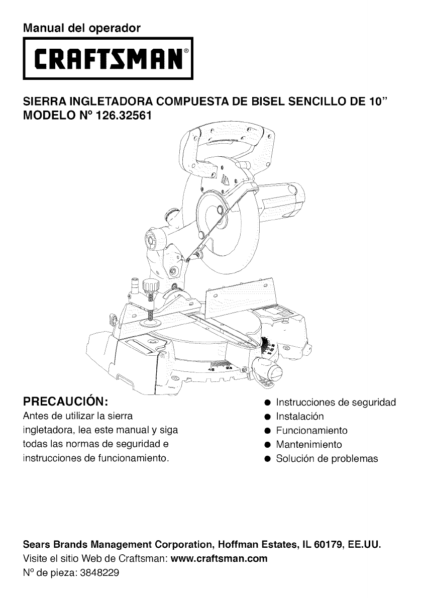
Manual del operador
CRItFTSMI:INi
SIERRA INGLETADORA COMPUESTA DE BISEL SENCILLO DE 10"
MODELO N° 126.32561
PRECAUCION:
Antes de utilizar la sierra
ingletadora, lea este manual y siga
todas las normas de seguridad e
instrucciones de funcionamiento.
•Instrucciones de seguridad
• Instalaci6n
• Funcionamiento
• Mantenimiento
• Soluci6n de problemas
Sears Brands Management Corporation, Hoffman Estates, IL 60179, EE.UU.
Visite el sitio Web de Craftsman: www.craftsman.com
N° de pieza: 3848229
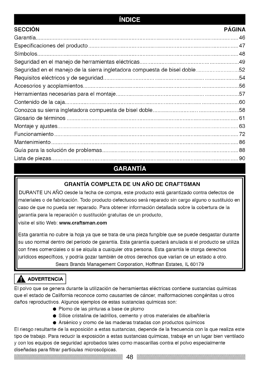
SECCION PAGINA
Garantia ................................................................................................................................... 46
Especificaciones det producto ................................................................................................. 47
Simbolos .................................................................................................................................. 48
Seguridad en et manejo de herramientas electricas ................................................................ 49
Seguridad en el manejo de la sierra ingletadora compuesta de biset dobte ............................ 52
Requisitos etectricos y de seguridad ....................................................................................... 54
Accesorios y acoptamientos .................................................................................................... 56
Herramientas necesarias para et montaje ............................................................................... 57
Contenido de la caja ................................................................................................................ 60
Conozca su sierra ingletadora compuesta de biset dobte ....................................................... 58
Glosario de terminos ............................................................................................................... 61
Montaje y ajustes ..................................................................................................................... 63
Funcionamiento ....................................................................................................................... 72
Mantenimiento ......................................................................................................................... 86
Guia para la sotuci6n de probtemas ........................................................................................ 88
Lista de piezas ......................................................................................................................... 90
GRANT|A COMPLETA DE UN ANO DE CRAFTSMAN
DURANTE UN AlqO desde la fecha de compra, este producto est& garantizado contra defectos de
materiales o de fabricaci6n. Todo producto defectuoso ser& reparado sin cargo alguno o sustituido en
caso de que no pueda ser reparado. Para obtener informaci6n detallada sobre la cobertura de la
garantia para la reparaci6n o sustituci6n gratuitas de un producto,
visite el sitio Web: www.craftsman.com
Esta garantia no cubre la hoja ya que se trata de una pieza fungible que se puede desgastar durante
su uso normal dentro del periodo de garantia. Esta garantia quedar_, anulada si el producto se utiliza
con fines comerciales o si se alquila a cualquier otra persona. Esta garantia le otorga derechos
juridicos especificos, y podria gozar tambien de otros derechos que varian de un estado a otro.
Sears Brands Management Corporation, Hoffman Estates, IL 60179
,_ ADVERTENCIA l
El polvo que se genera durante la utilizaci6n de herramientas electricas contiene sustancias quimicas
que el estado de California reconoce como causantes de c&ncer, malformaciones congenitas u otros
daSos reproductivos. Algunos ejemplos de estas sustancias quimicas son:
• Plomo de las pinturas a base de plomo
• Silice cristalina de ladrillos, cemento y otros materiales de albaSileria
• Arsenico y cromo de las maderas tratadas con productos quimicos
El riesgo resultante de la exposici6n a estas sustancias, depende de la frecuencia con la que realiza este
tipo de trabajo. Para reducir la exposici6n aestas sustancias quimicas, trabaje en un lugar bien ventilado
y con los equipos de seguridad aprobados tales como mascarillas contra el polvo especialmente
diseSadas para filtrar particulas microsc6picas.
48
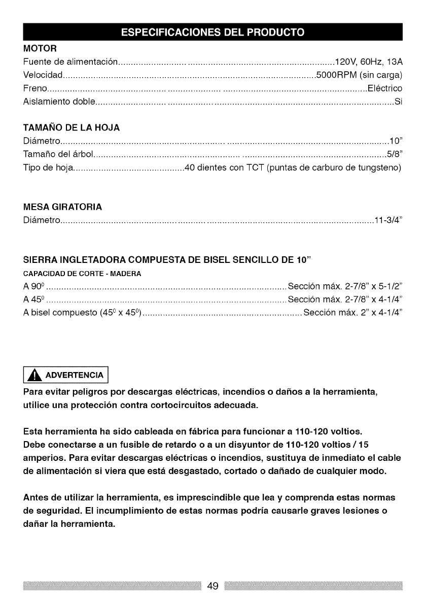
MOTOR
Fuente de atimentacion ..................................................................................... 120V, 60Hz, 13A
Vetocidad .................................................................................................... 5000RPM (sin carga)
Freno ............................................................................................................................. Electrico
Aislamiento dobte ..................................................................................................................... Si
TAMANO DE LA HOJA
Dia.metro ................................................................................................................................. 10"
Tamafio det a.rbot................................................................................................................... 5/8"
Tipo de hoja ............................................ 40 dientes con TCT (puntas de carburo de tungsteno)
MESA GIRATORIA
Dia.metro ........................................................................................................................... 11-3/4"
SIERRA INGLETADORA COMPUESTA DE BISEL SENClLLO DE 10"
CAPAClDAD DE CORTE - MADERA
A 90 o............................................................................................... Seccion ma.x. 2-7/8" x 5-1/2"
A 45 o............................................................................................... Seccion ma.x. 2-7/8" x 4-1/4"
A biset compuesto (45 ox 45°)............................................................... Seccion ma.x. 2" x 4-1/4"
l, _ ADVERTENCIA J
Para evitar peligros por descargas electricas, incendios o dafios a la herramienta,
utilice una proteccibn contra cortocircuitos adecuada.
Esta herramienta ha sido cableada en fabrica para funcionar a 110-120 voltios.
Debe conectarse a un fusible de retardo o a un disyuntor de 110-120 voltios/15
amperios. Para evitar descargas electricas o incendios, sustituya de inmediato el cable
de alimentacibn si viera que esta desgastado, cortado o dafiado de cualquier modo.
Antes de utilizar la herramienta, es imprescindible que lea y comprenda estas normas
de seguridad. El ineumplimiento de estas normas podria eausarle graves lesiones o
dafiar la herramienta.
49
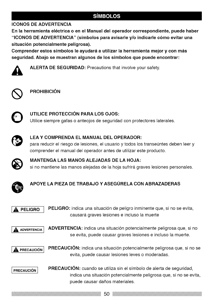
ICONOS DE ADVERTENCIA
En la herramienta electrica o en el Manual del operador correspondiente, puede haber
"ICONOS DE ADVERTENCIA" (simbolos para avisarle y/o indicarle cbmo evitar una
situacibn potencialmente peligrosa).
Comprender estos simbolos le ayudara a utilizar la herramienta mejor y con mas
seguridad. Abajo se muestran algunos de los simbolos que puede encontrar:
ALERTA DE SEGURIDAD: Precautions that involve your safety.
(_ PROHIBICION
UTILICE PROTECCION PARA LOS OJOS:
Utilice siempre gafas o anteojos de seguridad con protectores laterates.
LEA Y COMPRENDA EL MANUAL DEL OPERADOR:
para reducir et riesgo de lesiones, el usuario y todos los transe_ntes deben leer y
comprender el manual del operador antes de utitizar este producto.
MANTENGA LAS MANOS ALEJADAS DE LA HOJA:
si no mantiene las manos atejadas de la hoja sufrira, graves lesiones personates.
OAPOYELA PIEZA DETRABAJO Y ASEGURELA CON ABRAZADERAS
i_, PELIGRO IPELIGRO: indica una situacion de petigro inminente que, si no se evita,
causara, graves lesiones e incluso la muerte
L,_i ADVERTENCIAI ADVERTENCIA: indica una situacion potenciatmente peNgrosa que, si no
se evita, puede causar graves lesiones e incluso la muerte.
L,_ PRECAUCI(_NI PRECAUCION: indica una situacion potenciatmente petigrosa que, si no se
evita, puede causar lesiones leves o moderadas.
LPRECAUCION JPRECAUClON: cuando se utitiza sin et sfmboto de alerta de seguridad,
indica una situacion potencialmente petigrosa que, si no se evita,
puede causar da5os materiates.
50
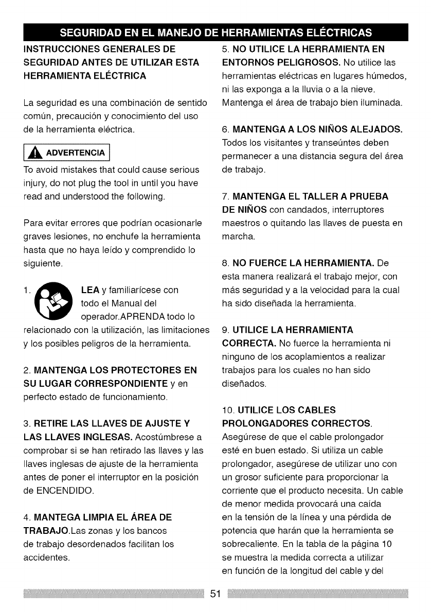
INSTRUCCIONES GENERALES DE
SEGURIDAD ANTES DE UTILIZAR ESTA
HERRAMIENTA ELC:CTRICA
La seguridad es una combinacion de sentido
comOn, precaucion y conocimiento det uso
de la herramienta etectrica.
[,_ ADVERTENCIA l
To avoid mistakes that could cause serious
injury, do not plug the tool in until you have
read and understood the following.
Para evitar errores que podrian ocasionarte
graves lesiones, no enchufe la herramienta
hasta que no haya leido y comprendido Io
siguiente.
A
1. _ LEA y familiaricese con
todo et Manual det
operador.APRENDA todo lo
retacionado con la utitizaci6n, las limitaciones
y los posibtes petigros de la herramienta.
2. MANTENGA LOS PROTECTORES EN
SU LUGAR CORRESPONDIENTE y en
perfecto estado de funcionamiento.
3. RETIRE LAS LLAVES DE AJUSTE Y
LAS LLAVES INGLESAS. Acostumbrese a
comprobar si se han retirado las Ilaves y las
Itaves inglesas de ajuste de la herramienta
antes de poner et interruptor en la posici6n
de ENCENDIDO.
4. MANTEGA LIMPIA EL AREA DE
TRABAJO.Las zonas y los bancos
de trabajo desordenados facilitan los
accidentes.
5. NO UTILICE LA HERRAMIENTA EN
ENTORNOS PELIGROSOS. No utilice las
herramientas etectricas en lugares humedos,
ni las exponga a la Iluvia o a la nieve.
Mantenga el a.rea de trabajo bien iluminada.
6. MANTENGA A LOS NINOS ALEJADOS.
Todos los visitantes y transeOntes deben
permanecer a una distancia segura det a.rea
de trabajo.
7. MANTENGA EL TALLER APRUEBA
DE NINOS con candados, interruptores
maestros o quitando las Ilaves de puesta en
marcha.
8. NO FUERCE LA HERRAMIENTA. De
esta manera realizara, et trabajo mejor, con
ma.s seguridad y a la velocidad para la cuat
ha sido disefiada la herramienta.
9. UTILICE LA HERRAMIENTA
CORRECTA. No fuerce la herramienta ni
ninguno de los acoplamientos a realizar
trabajos para los cuates no han sido
disefiados.
10. UTILICE LOS CABLES
PROLONGADORES CORRECTOS.
Asegurese de que et cable prolongador
este en buen estado. Si utiliza un cable
prolongador, asegurese de utilizar uno con
un grosor suficiente para proporcionar la
corriente que et producto necesita. Un cable
de menor medida provocara, una caida
en ta tensi6n de la linea y una perdida de
potencia que hara.n que ta herramienta se
sobrecatiente. En la tabta de la pa.gina 10
se muestra la medida correcta a utilizar
en funci6n de la Iongitud det cable y del
51
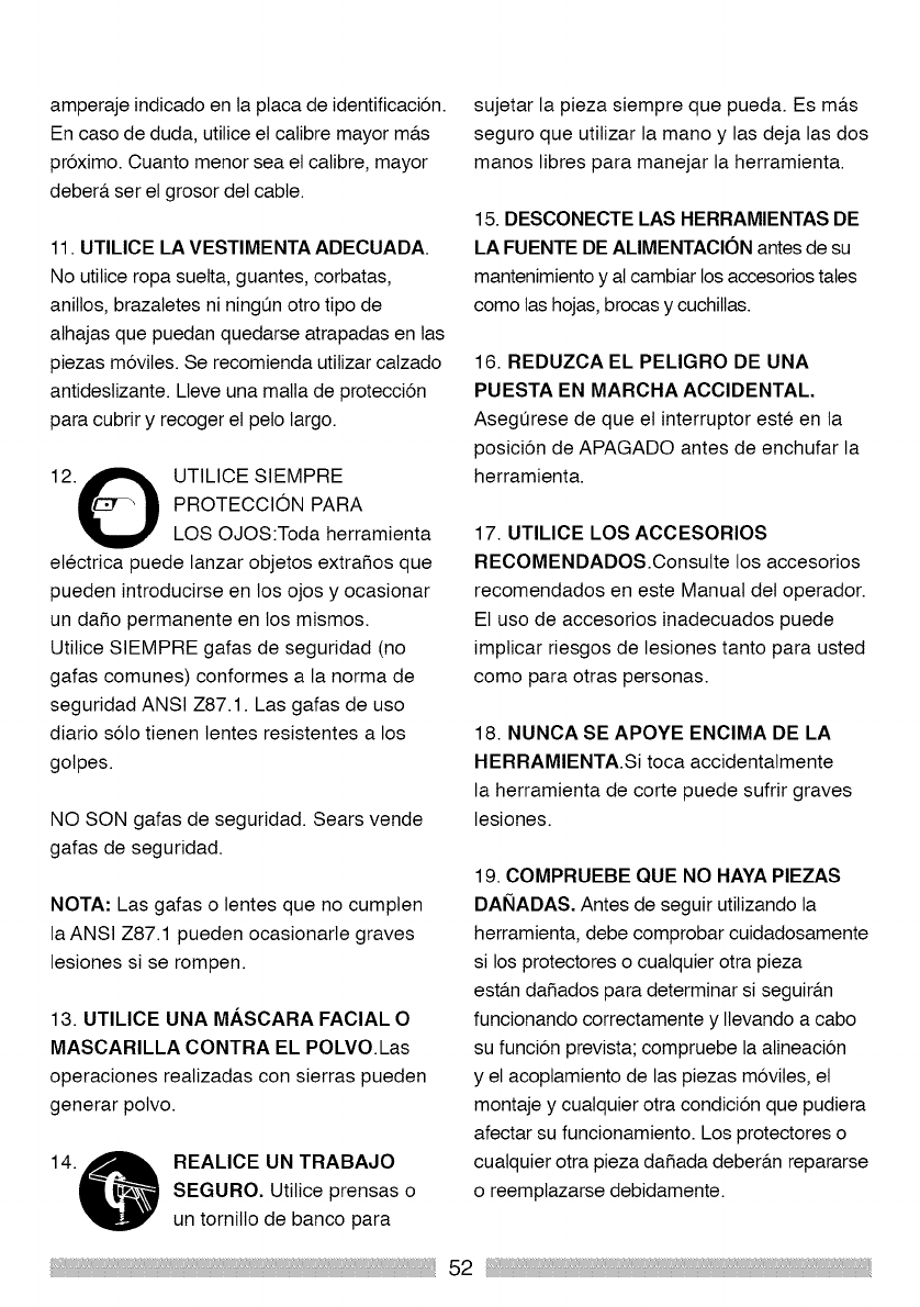
amperaje indicado en la ptaca de identificacion.
En caso de duda, utilice el calibre mayor ma.s
proximo. Cuanto menor sea el calibre, mayor
debera, ser el grosor del cable.
11. UTILICE LA VESTIMENTA ADECUADA.
No utilice ropa suelta, guantes, corbatas,
anillos, brazaletes ni ningun otro tipo de
athajas que puedan quedarse atrapadas en tas
piezas moviles. Se recomienda utilizar calzado
antideslizante. Lleve una malta de proteccion
para cubrir y recoger el pelo largo.
12.O UTILICE SIEMPRE
PROTECCION PARA
LOS OJOS:Toda herramienta
etectrica puede lanzar objetos extrafios que
pueden introducirse en los ojos y ocasionar
un dafio permanente en los mismos.
Utilice SlEMPRE gafas de seguridad (no
gafas comunes) conformes a la norma de
seguridad ANSI Z87.1. Las gafas de uso
diario solo tienen lentes resistentes a los
gotpes.
NO SON gafas de seguridad. Sears vende
gafas de seguridad.
NOTA: Las gafas o lentes que no cumpten
la ANSI Z87.1 pueden ocasionarte graves
lesiones si se rompen.
13. UTILICE UNA MASCARA FACIAL O
MASCARILLA CONTRA EL POLVO.Las
operaciones realizadas con sierras pueden
generar polvo.
REALICE UN TRABAJO
SEGURO. Utilice prensas o
un tornillo de banco para
sujetar la pieza siempre que pueda. Es ma.s
seguro que utilizar la mano y las deja las dos
manos libres para manejar la herramienta.
15. DESCONECTE LAS HERRAMIENTAS DE
LA FUENTE DE ALIMENTAClON antes de su
mantenimiento y al cambiar los accesorios tales
como las hojas, brocas y cuchillas.
16. REDUZCA EL PELIGRO DE UNA
PUESTA EN MARCHA ACCIDENTAL.
Asegurese de que el interruptor este en la
posicion de APAGADO antes de enchufar la
herramienta.
17. UTILICE LOS ACCESORIOS
RECOMENDADOS.Consulte los accesorios
recomendados en este Manual del operador.
El uso de accesorios inadecuados puede
impticar riesgos de lesiones tanto para usted
como para otras personas.
18. NUNCA SE APOYE ENClMA DE LA
HERRAMIENTA.Si toca accidentatmente
la herramienta de corte puede sufrir graves
lesiones.
19. COMPRUEBE QUE NO HAYA PIEZAS
DANADAS. Antes de seguir utilizando la
herramienta, debe comprobar cuidadosamente
si los protectores o cualquier otra pieza
est&n dafiados para determinar si seguira.n
funcionando correctamente y Itevando a cabo
su funcion prevista; compruebe la alineacion
y el acoptamiento de las piezas moviles, et
montaje y cualquier otra condicion que pudiera
afectar su funcionamiento. Los protectores o
cualquier otra pieza dafiada debera.n repararse
o reemptazarse debidamente.
52
20. NUNCA DEJE DESATENDIDA LA
HERRAMIENTA EN FUNCIONAMIENTO.
PONGA EL INTERRUPTOR EN LA
POSICION "APAGADO'. No se aleje nunca
dejando una herramienta en funcionamiento
hasta que no se haya parado ta hoja
por compteto y la herramienta se haya
desenchufado de la fuente de atimentacion.
21. NO FUERCE LA POSTURA. Mantenga
los pies bien colocados y et equiNbrio en
todo momento.NO ponga nunca la mano o el
brazo en la trayectoria de la hoja de corte.
22. MANTENGA LAS HERRAMIENTAS CON
CUlDADO.Mantenga las herramientas afiladas
y limpias para un funcionamiento mejor y ma.s
seguro. Siga las instruccionesde lubricacion y
reemptazo de los accesorios.
23. ADVERTENCIA: El potvo generado por
ciertos materiales puede ser nocivo para su
satud. Utilice siempre la sierra en tugares
bien ventilados y disponga medios para la
etiminacion correcta del potvo.
PELIGRO l
24. Las personas con dispositivos
electrbnicos, tales como marcapasos,
deben consultar al medico antes de
utilizar este producto. El funcionamiento
det equipo electrico cerca de un marcapasos
puede causar interferencias o fattos en et
marcapasos.
53

INSTRUCCIONES DE SEGURIDAD
ESPECiFICAS PARA ESTA SIERRA
INGLETADORA COMPUESTA
1. NO UTILICE HOJAS CON UN ANCHO
DE CORTE FINO ya que pueden dobtarse y
entrar en contacto con et protector y causar
lesiones at operador.
2. NO ponga en funcionamiento la sierra
ingletadora hasta que no haya quedado
montada pot compteto e instalada segun
estas instrucciones.
3. Sl NO EST,&,completamente famitiarizado
con el funcionamiento de las sierras
ingletadoras, pida ayuda a su supervisor,
instructor o cuatquier otra persona
cuatificada.
4. SlEMPRE sujete la pieza de trabajo
firmemente contra la guia y sobre la mesa.
NO realice ninguna operaci6n a putso. Utilice
una prensa para asegurar la pieza de trabajo
siempre que sea posibte.
5. MANTENGA LAS MANOS fuera de la
trayectoria de la hoja de la sierra.
Si la pieza de trabajo que est& cortando hace
que sus manos queden a una distancia menor
de 20,32 cm de la hoja de sierra, la pieza de
trabajo se debe fijar con prensas en su tugar
correspondiente antes de realizar el corte.
6. ASEGURESE de que la hoja este afitada,
gire libremente y no vibre.
7. DEJE que el motor atcance su vetocidad
ma.xima antes de empezar a cortar.
8. MANTENGA LAS RANURAS DE
VENTILAClON DEL MOTOR LIMPIAS y sin
virutas ni polvo.
9. ASEGURESE SIEMPRE de que todos
los mangos esten bien apretados antes de
cortar, incluso si la mesa est& colocada en
uno de los topes positivos.
10. ASEGURESE de que tanto la hoja como
et anillo esten limpios y de que et perno det
a.rbol este bien apretado.
11. UTILICE Qnicamente los anillos para
hojas especificados para la sierra.
12. NUNCA utilice hojas de ma.s de 10" de
dia.metro.
13. NUNCA aptique lubricantes a la hoja
mientras la herramienta se encuentra en
funcionamiento.
14. SlEMPRE compruebe que la hoja no
tenga grietas ni daSos antes de utilizar la
herramienta. Reemplace inmediatamente
cuatquier hoja con grietas o daSada.
15. NUNCA utilice hojas recomendadas para
funcionar a menos de 5000 rpm.
16. SlEMPRE mantenga los protectores
de la hoja en su lugar correspondiente y
utilicelos en todo momento.
17. NUNCA extienda el brazo cerca de la
hoja de la sierra.
54
18. ASEGORESE de que la hoja no este en
contacto con la pieza de trabajo antes poner
et interruptor en la posici6n de ENCENDIDO.
19. IMPORTANTE: una vez reatizado et
corte, suette el gatillo y espere hasta que la
hoja se detenga antes de volver a poner la
sierra en la posici6n etevada.
20. ASEGORESE de que la hoja se haya
detenido por compteto antes de retirar o
asegurar la pieza de trabajo, cambiar et
a.nguto de la pieza de trabajo o cambiar el
a.nguto de la hoja.
21. UTILICE ESTA SIERRA INGLETADORA
COMPUESTA 0NICAMENTE PARA madera
y matefiales a base de madera. NO la utilice
para cortar materiales a base de acero
inoxidabte, matefiales de albafiileria o asbesto.
22. NUNCA corte piezas pequefias. La pieza
de trabajo que va a cortar sera. demasiado
pequefia si al sujetarla sus manos o sus
dedeos quedan a menos de 6-3/8" de
distancia de la hoja de la sierra.
23. COLOQUE un soporte adecuado a los
lados de la mesa de la sierra para las piezas
de trabajo grandes.
24. NUNCA utilice la sierra ingletadora
en a.reas donde haya liquidos o gases
inflamabtes.
25. NUNCA utilice disotventes para limpiar
las piezas de pta.stico. Los disolventes
podrian disolverse o dafiar de cualquier otra
forma et material.
26. CORTE ta fuente de atimentaci6n de
energia antes del mantenimiento o det ajuste
de la herramienta.
27. DESCONECTE la sierra de la fuente de
alimentaci6n y limpie la ma.quina una vez
finatizado et corte.
28. ASEGORESE de que et a.rea de trabajo
este limpia antes de dejar la ma.quina.
29. Sl alguna de las piezas de la sierra
ingletadora se ha perdido, dafiado o falla
de alguna manera, o si algun componente
etectrico no funciona correctamente, trabe et
interruptor y desenchufe la clavija de la toma
de corriente. Reemptace las piezas perdidas,
dafiadas o averiadas antes de continuar con
la operaci6n
55
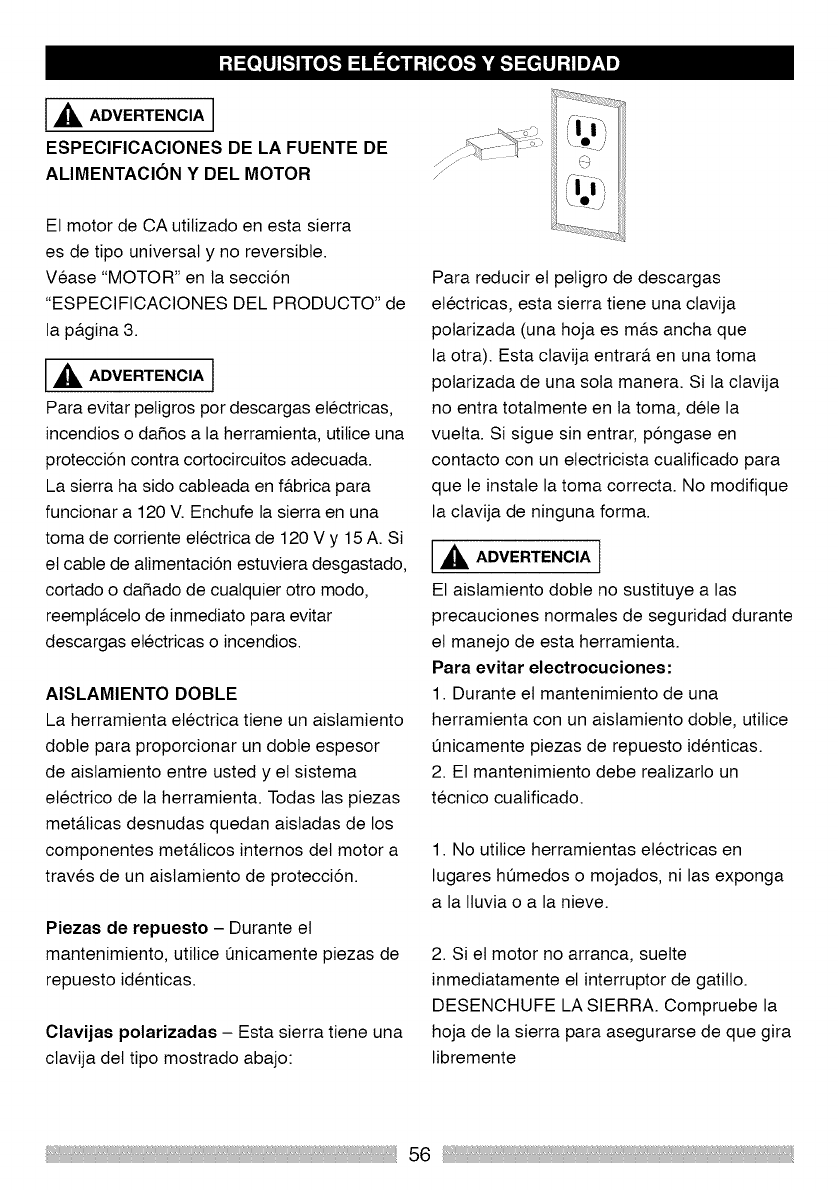
_k ADVERTENCIA
ESPECIFICACIONES DE LA FUENTE DE
ALIMENTACION Y DEL MOTOR
El motor de CA utilizado en esta sierra
es de tipo universal y no reversible.
Vease "MOTOR" en la seccion
"ESPEClFICACIONES DEL PRODUCTO" de
la pa.gina 3.
,_ ADVERTENCIA l
Para evitar peligros por descargas electricas,
incendios o dafios a la herramienta, utilice una
protecci6n contra cortocircuitos adecuada.
La sierra ha sido cabteada en f&brica para
funcionar a 120 V. Enchufe la sierra en una
toma de corriente etectrica de 120 V y 15 A. Si
et cable de alimentaci6n estuviera desgastado,
cortado o dafiado de cualquier otro modo,
reempta.celo de inmediato para evitar
descargas etectricas o incendios.
AISLAMIENTO DOBLE
La herramienta etectrica tiene un aislamiento
dobte para proporcionar un dobte espesor
de aislamiento entre usted y el sistema
etectrico de la herramienta. Todas las piezas
met&ticas desnudas quedan aisladas de los
componentes met&licos internos del motor a
traves de un aislamiento de protecci6n.
Piezas de repuesto - Durante el
mantenimiento, utilice 0nicamente piezas de
repuesto identicas.
Clavijas polarizadas - Esta sierra tiene una
clavija det tipo mostrado abajo:
Para reducir et peligro de descargas
etectricas, esta sierra tiene una clavija
polarizada (una hoja es ma.s ancha que
la otra). Esta clavija entrara, en una toma
polarizada de una sola manera. Si la clavija
no entra totatmente en la toma, dete la
vuelta. Si sigue sin entrar, pongase en
contacto con un etectricista cuatificado para
que le instate la toma correcta. No modifique
la clavija de ninguna forma.
ADVERTENCIA t
El aislamiento dobte no sustituye alas
precauciones normales de seguridad durante
et manejo de esta herramienta.
Para evitar eleetroeueiones:
1. Durante et mantenimiento de una
herramienta con un aislamiento dobte, utilice
0nicamente piezas de repuesto identicas.
2. El mantenimiento debe reatizarto un
tecnico cuatificado.
1. No utilice herramientas etectricas en
lugares humedos o mojados, ni las exponga
a la Ituvia o a la nieve.
2. Si et motor no arranca, suelte
inmediatamente et interruptor de gatitlo.
DESENCHUFE LA SIERRA. Compruebe la
hoja de la sierra para asegurarse de que gira
libremente
56
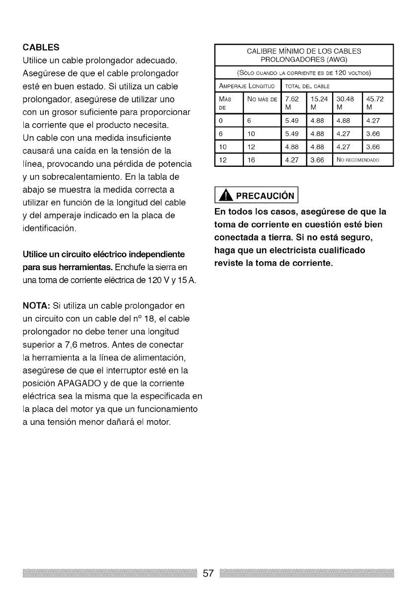
CABLES
Utilice un cable prolongador adecuado.
Asegurese de que et cable prolongador
este en buen estado. Si utitiza un cable
prolongador, asegurese de utitizar uno
con un grosor suficiente para proporcionar
la corriente que el producto necesita.
Un cable con una medida insuficiente
causara, una caida en la tensi6n de la
linea, provocando una perdida de potencia
y un sobrecalentamiento. En la tabta de
abajo se muestra la medida correcta a
utilizar en funci6n de la Iongitud det cable
y del amperaje indicado en la ptaca de
identificaci6n.
Utilice un circuito electrico independiente
para sus herramientas. Enchufe la sierra en
una toma de corriente etectrica de 120 V y 15A.
NOTA: Si utitiza un cable prolongador en
un circuito con un cable det n° 18, et cable
prolongador no debe tenet una Iongitud
superior a 7,6 metros. Antes de conectar
la herramienta a la linea de alimentaci6n,
asegurese de que et interruptor este en la
posicion APAGADO y de que la corriente
etectrica sea la misma que la especificada en
la placa det motor ya que un funcionamiento
a una tension menor dafiara, et motor.
CALIBRE MiNIMO DE LOS CABLES
PROLONGADORES (AWG)
(SOLo CUANDO LA CORRIENTE ES DE 120 VOLTIOS)
AMPERAJE L©NGITUD TOTAL DEL CABLE
MRS No MASDE 7.62 15.24 30.48 45.72
DE M M M M
0 6 5.49 4.88 4.88 4.27
6 10 5.49 4.88 4.27 3.66
10 12 4.88 4.88 4.27 3.66
12 16 4.27 3.66 No RECOMENDADO
IA P.ECAUC;O.I
En todos los casos, asegerese de que la
toma de corriente en cuesti6n este bien
coneetada a tierra. Si no esta seguro,
haga que un eleetrieista cualifieado
reviste la toma de corriente.
57
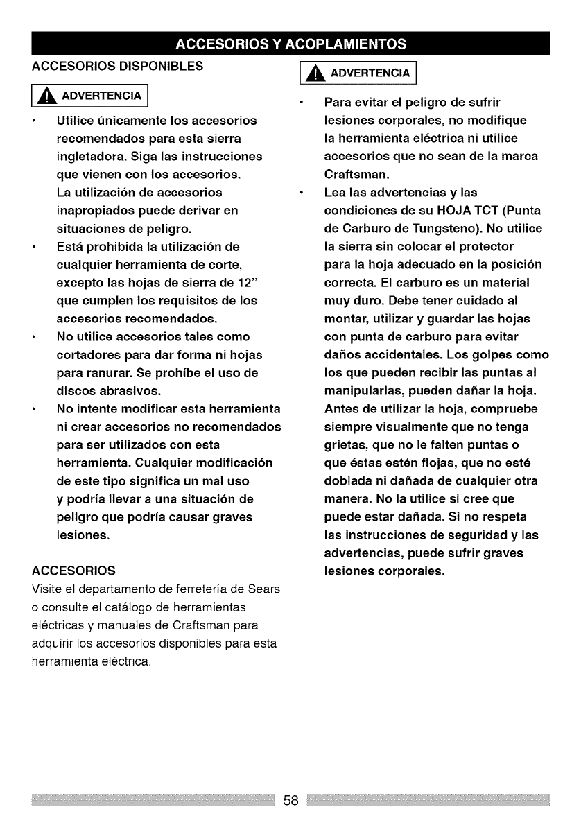
ACCESORIOS DISPONIBLES
,_ ADVERTENCIA 1
Utilice t_nicamente los accesorios
recomendados para esta sierra
ingletadora. Siga las instrucciones
que vienen con los accesorios.
La utilizacibn de accesorios
inapropiados puede derivar en
situaciones de peligro.
Esta prohibida la utilizacibn de
cualquier herramienta de corte,
excepto las hojas de sierra de 12"
que cumplen los requisitos de los
accesorios recomendados.
No utilice accesorios tales como
cortadores para dar forma ni hojas
para ranurar. Se prohibe el uso de
discos abrasivos.
No intente modificar esta herramienta
ni crear accesorios no recomendados
para set utilizados con esta
herramienta. Cualquier modificacibn
de este tipo significa un mal uso
y podria Ilevar a una situacibn de
peligro que podria causar graves
lesiones.
ACCESORIOS
Visite et departamento de ferreteria de Sears
o consutte et cat&logo de herramientas
etectricas y manuates de Craftsman para
adquirir los accesorios disponibtes para esta
herramienta etectrica.
I,_ ADVERTENCIA ]
Para evitar el peligro de sufrir
lesiones corporales, no modifique
la herramienta electrica ni utilice
accesorios que no sean de la marca
Craftsman.
Lea las advertencias y las
condiciones de su HOJA TCT (Punta
de Carburo de Tungsteno). No utilice
la sierra sin colocar el protector
para la hoja adecuado en la posicibn
correcta. El carburo es un material
muy duro. Debe tener cuidado al
montar, utilizar y guardar las hojas
con punta de carburo para evitar
da_os accidentales. Los golpes como
los que pueden recibir las puntas al
manipularlas, pueden da_ar la hoja.
Antes de utilizar la hoja, compruebe
siempre visualmente que no tenga
grietas, que no le falten puntas o
que estas esten flojas, que no este
doblada ni da_ada de cualquier otra
manera. No la utilice si cree que
puede estar da_ada. Si no respeta
las instrucciones de seguridad y las
advertencias, puede sufrir graves
lesiones corporales.
58
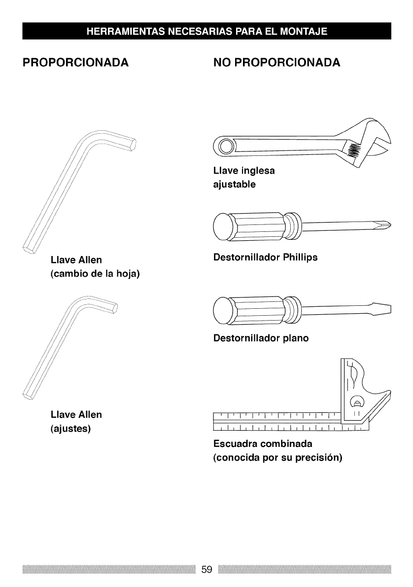
PROPORClONADA NO PROPORClONADA
/
/
/
/
/
Llave Allen
(cambio de la hoja)
Llave inglesa
ajustable
Destornillador Phillips
Llave Allen
(ajustes)
Destornillador piano
,I,1,t,t,I,I,1,1_1 _
Escuadra combinada
(conocida pot su precisibn)
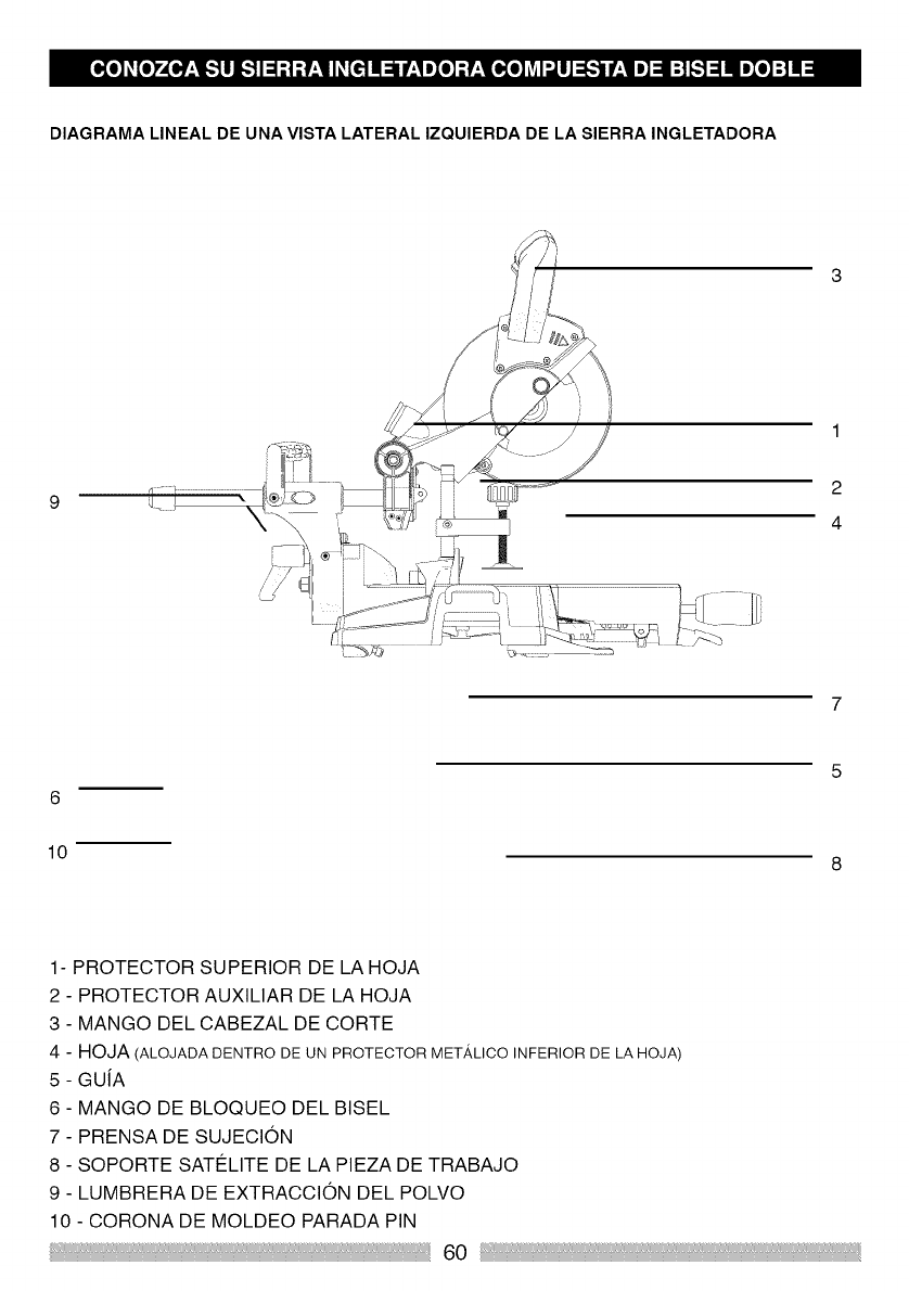
DIAGRAMA LINEAL DE UNA VISTA LATERAL IZQUIERDA DE LA SIERRA INGLETADORA
9
1
2
4
6
lO
1- PROTECTOR SUPERIOR DE LA HOJA
2 - PROTECTOR AUXILIAR DE LA HOJA
3 - MANGO DEL CABEZAL DE CORTE
4 - HOJA (ALOJADA DENTRO DE UN PROTECTOR METALICO INFERIOR DE LA HOJA)
5- GUiA
6- MANGO DE BLOQUEO DEL BISEL
7- PRENSA DE SUJECION
8- SOPORTE SATELITE DE LA PIEZA DE TRABAJO
9- LUMBRERA DE EXTRACCION DEL POLVO
10 - CORONA DE MOLDEO PARADA PIN
60
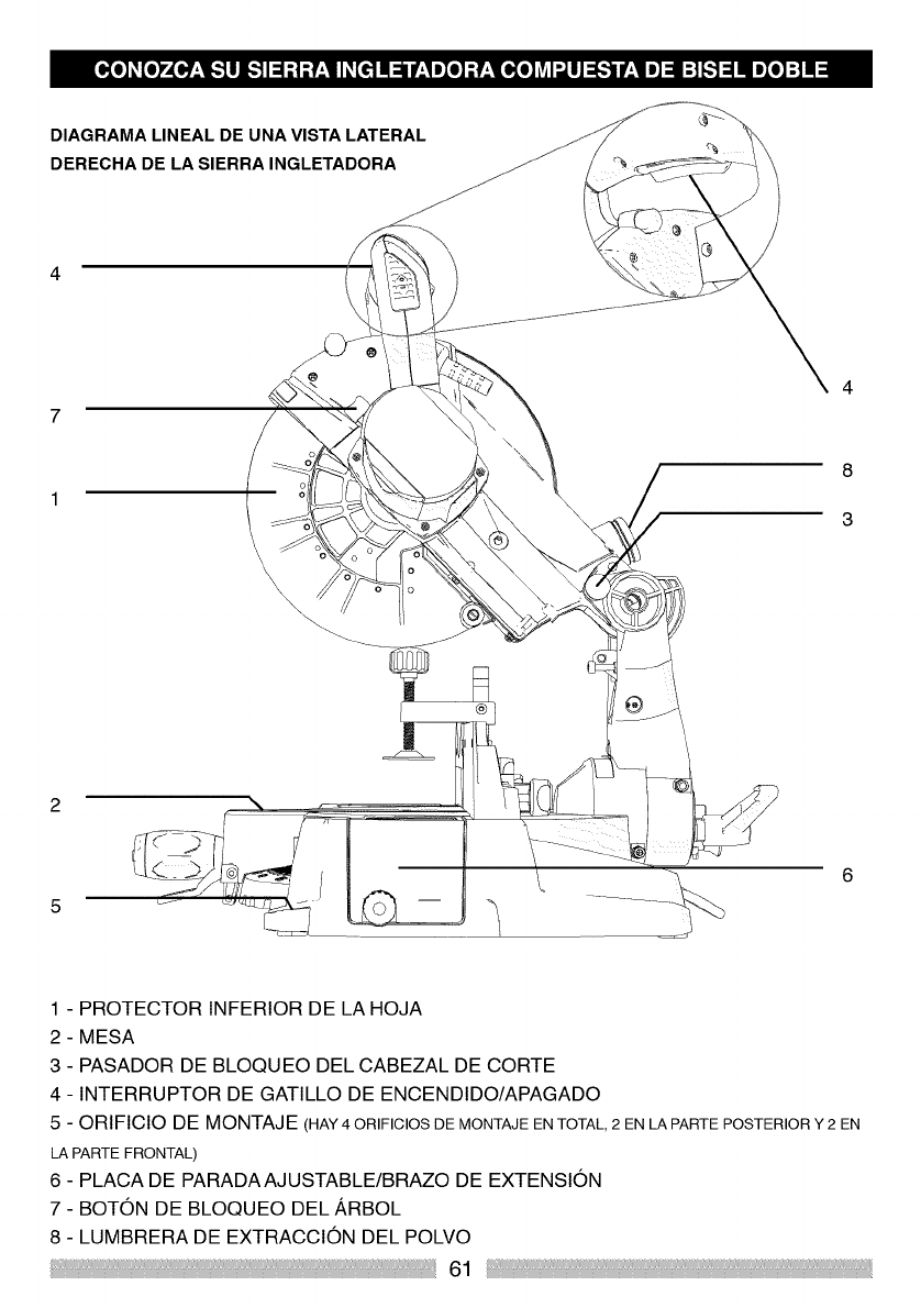
DIAGRAMA LINEAL DE UNA VISTA LATERAL
DERECHA DE LA SIERRA INGLETADORA
4
7
8
3
2
1 - PROTECTOR INFERIOR DE LA HOJA
2 - MESA
3 - PASADOR DE BLOQUEO DEL CABEZAL DE CORTE
4 - INTERRUPTOR DE GATILLO DE ENCENDIDO/APAGADO
5 - ORIFICIO DE MONTAJE (HAY 40RIFIClOS DE MONTAJE EN TOTAL, 2 EN LA PARTE POSTERIOR Y 2 EN
LA PARTE FRONTAL)
6 - PLACA DE PARADAAJUSTABLE/BRAZO DE EXTENSION
7 - BOTON DE BLOQUEO DEL ARBOL
8 - LUMBRERA DE EXTRACCION DEL POLVO
61
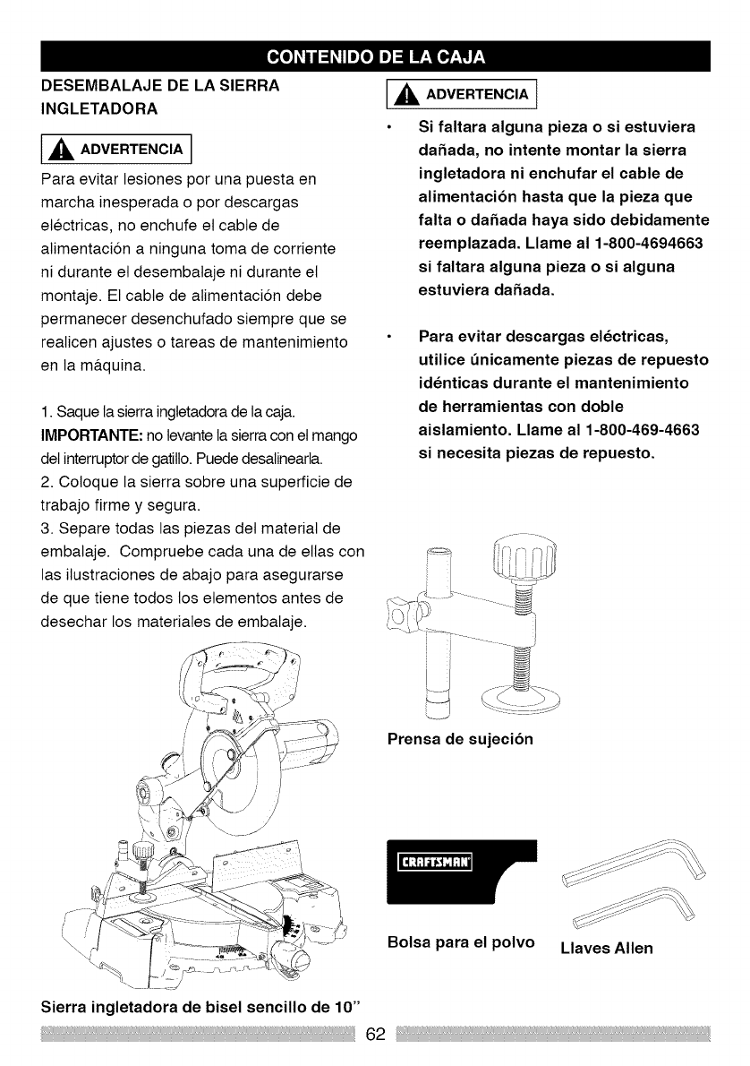
DESEMBALAJE DE LA SIERRA
INGLETADORA
,_ ADVERTENCIA
Para evitar lesiones por una puesta en
marcha inesperada o por descargas
etectricas, no enchufe et cable de
atimentaci6n a ninguna toma de corriente
ni durante et desembataje ni durante el
montaje. El cable de atimentaci6n debe
permanecer desenchufado siempre que se
realicen ajustes o tareas de mantenimiento
en la ma.quina.
1. Saque la sierra ingtetadorade la caja.
IMPORTANTE: no tevante la sierracon et mango
det interruptorde gatillo. Puede desalinearla.
2. Coloque la sierra sobre una superficie de
trabajo firme y segura.
3. Separe todas las piezas det material de
embalaje. Compruebe cada una de elias con
las ilustraciones de abajo para asegurarse
de que tiene todos los etementos antes de
desechar los materiates de embalaje.
_L ADVERTENCIA I
Si faltara alguna pieza o si estuviera
daSada, no intente montar la sierra
ingletadora ni enchufar el cable de
alimentacibn hasta que la pieza que
falta o daSada haya sido debidamente
reemplazada. Llame al 1-800-4694663
si faltara alguna pieza o si alguna
estuviera daSada.
Para evitar descargas electricas,
utilice dnicamente piezas de repuesto
identicas durante el mantenimiento
de herramientas con doble
aislamiento. Llame al 1-800-469-4663
si necesita piezas de repuesto.
Prensa de sujecibn
Bolsa para el polvo Llaves Allen
Sierra ingletadora de bisel sencillo de 10"
62
AMPERAJE (AMPS) - Una medida det
flujo de corriente etectrica. Unos amperajes
ma.s altos normatmente significan que
la herramienta es adecuada para una
capacidad mayor.
ARBOL - El eje sobre el que se monta la hoja.
TRABA DEL ARBOL - Le permite evitar que
la hoja gire mientras aprieta o afloja et perno
det a.rbot durante et reemptazo o retirada de
la hoja.
BASE - Sostiene la mesa, sujeta los
accesorios y permite et montaje sobre un
banco de trabajo o sobre un juego de patas.
CORTE EN BISEL - Corte angular realizado a
traves de la superficie de la pieza de trabajo.
MANGO DE BLOQUEO DE BISEL -
Btoquea la sierra ingletadora en un a.nguto
de bisel deseado.
ESCALA DE BISEL - Se utiliza para medir el
a.nguto de bisel de la hoja de la sierra de 0 ° a
45o hacia la izquierda.
PUNTA DE CARBURO DE TUNGSTENO
(TCT) - Piezas de acero extremadamente
duras con fitos de corte afitados fijados a
herramientas de corte tales como hojas de
sierras.
CORTE COMPUESTO - Una combinaci6n
de un a.nguto de inglete y un a.ngulo de biset.
PASADOR DE BLOQUEO DEL
CABEZAL DE CORTE - BIoquea la sierra
ingletadora en la posicion inferior para un
atmacenamiento y transporte compactos.
AISLAMIENTO DOBLE - Un tipo de
protecci6n etectrica que se caracteriza
porque incluye dos sistemas de aislamiento
independientes para ayudar a proteger
contra descargas etectricas.
ESCALA DE INGLETES - Indica et a.nguto
de inglete seteccionado de 00 a 450 hacia la
izquierda y hacia la derecha.
CABLE PROLONGADOR - Un cable
etectrico utilizado entre herramientas
etectricas y tomas de atimentaci6n para
prolongar la distancia entre ambas. Cuanto
ma.s amperaje utilice la herramienta y mayor
sea la distancia, mayor sera. la Iongitud det
cable prolongador.
PROTECClON PARA LOS OJOS - Lentes
o galas destinadas a proteger los ojos. La
proteccion para los ojos debe cumplir los
requisitos de la ANSI Z.87.1 (EE.UU.) o de la
CSA Z94.3-M88 (CANADA).
MASCARA FACIAL - Una ma.scara
resistente a los impactos para protegerle
la cara de las virutas, chipas, particutas de
polvo. S61o debe set utilizada junto con una
protecci6n para los ojos adicional.
GUJA - Ayuda a evitar que la pieza de trabajo
se mueva durante las operaciones de corte.
63
PROTECTOR - Dispositivo de proteccion
que forma una barrera entre un objeto
petigroso tat como una hoja, disco o cuchilla
y et operador.
PRENSA DE SUJEClON - Asegura la pieza
de trabajo durante las operaciones de corte.
MANUAL DE OPERADOR - LibriNo que
acompafia a su herramienta etectrica y
en et que se describen los petigros y los
procedimientos de manejo seguro y se
expNcan los procesos de funcionamiento,
cuidado y mantenimiento ba.sicos de la
herramienta.
ANCHO DE CORTE - La anchura de un
corte de sierra determinada por et grosor y
ajuste de la hoja.
ORIFIClOS DE MONTAJE - Se utiNzan para
montar la sierra ingletadora en una superficie
de trabajo plana y estabte.
INTERRUPTOR DE GATILLO DE
ENCENDIDO/APAGADO - Para poner en
marcha la herramienta, apriete et gatillo.
Para APAGAR la sierra ingletadora, suette et
gatitlo.
REVOLUClONES POR MINUTO (rpm) - El
numero de vueltas o rotaciones reatizadas
por un objeto giratorio en un minuto.
TRAYECTORIA DE LA HOJA DE SIERRA -
El a.rea de la pieza de trabajo o de la parte
superior de la mesa directamente en Ifnea
con et desptazamiento de la hoja o de la
parte de la pieza de trabajo que se va a
cortar.
CONTRAGOLPE - Movimiento repentino e
inesperado de la herramienta o de la pieza
de trabajo. Normatmente se produce at fijar o
inmovilizar la piezas de trabajo.
CORTE EN INGLETE - Un inglete es un tipo
de junta en donde las dos piezas a unir se
cortan en a.nguto y, normalmente, la junta
acabada forma un a.nguto de 90 grados.
MANGO DEL CABEZAL DE CORTE -
Contiene el interruptor de gatillo. La hoja se
baja empujando et mango hacia abajo. La
sierra volvera, a su posicion vertical at soltar
et mango.
ETIQUETAS DE ADVERTENCIA - Por su
propia seguddad lea y comprenda todas las
etiquetas pegadas a la ma.quina.
64
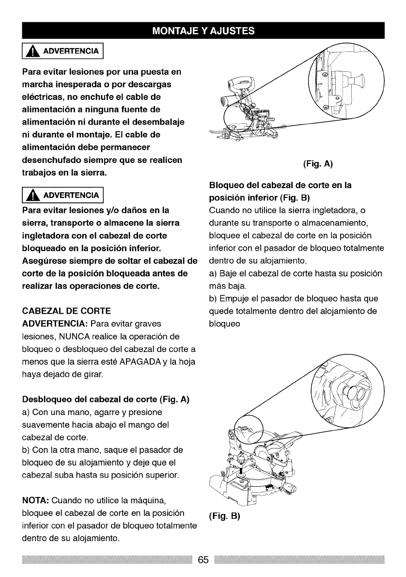
,_ ADVERTENCIA ]
Para evitar lesiones por una puesta en
marcha inesperada o por descargas
eldctricas, no enchufe el cable de
alimentacibn a ninguna fuente de
alimentacibn ni durante el desembalaje
ni durante el montaje. El cable de
alimentacibn debe permanecer
desenchufado siempre que se realicen
trabajos en la sierra.
,_IL ADVERTENCIA ]
Para evitar lesiones y/o da_os en la
sierra, transporte o almacene la sierra
ingletadora con el cabezal de corte
bloqueado en la posicibn inferior.
Asegdrese siempre de soltar el cabezal de
corte de la posicibn bloqueada antes de
realizar las operaciones de corte.
CABEZAL DE CORTE
ADVERTENCIA: Para evitar graves
lesiones, NUNCA realice la operaci6n de
bloqueo o desbloqueo del cabezal de corte a
menos que la sierra este APAGADA y la hoja
haya dejado de girar.
(Fig. A)
Bloqueo del cabezal de corte en la
posicibn inferior (Fig. B)
Cuando no utilice la sierra ingletadora, o
durante su transporte o almacenamiento,
bloquee el cabezal de corte en la posici6n
inferior con el pasador de bloqueo totalmente
dentro de su alojamiento.
a) Baje el cabezal de corte hasta su posici6n
m&s baja.
b) Empuje el pasador de bloqueo hasta que
quede totalmente dentro del alojamiento de
bloqueo
Desbloqueo del cabezal de corte (Fig. A)
a) Con una mano, agarre y presione
suavemente hacia abajo el mango del
cabezal de corte.
b) Con la otra mano, saque el pasador de
bloqueo de su alojamiento y deje que el
cabezal suba hasta su posici6n superior.
NOTA: Cuando no utilice la m&quina,
bloquee el cabezal de corte en la posici6n
inferior con el pasador de bloqueo totalmente
dentro de su alojamiento.
(Fig. B)
65
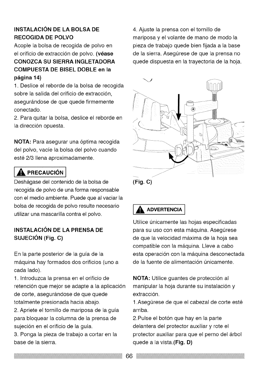
INSTALACION DE LA BOLSA DE
RECOGIDA DE POLVO
Acopte la bolsa de recogida de potvo en
et orificio de extraccion de polvo. (vease
CONOZCA SU SIERRA INGLETADORA
COMPUESTA DE BISEL DOBLE en la
pagina 14)
1. Destice et reborde de la bolsa de recogida
sobre la salida del orificio de extraccion,
asegur&ndose de que quede firmemente
conectado.
2. Para quitar la bolsa, deslice et reborde en
la direccion opuesta.
NOTA: Para asegurar una optima recogida
det polvo, vacie la botsa det potvo cuando
este 2/3 Itena aproximadamente.
_lk PRECAUCION I
Desh&gase del contenido de la bolsa de
recogida de potvo de una forma responsabte
con el medio ambiente. Puede que al vaciar la
botsa de recogida de potvo resulte necesario
utilizar una mascarilla contra el potvo.
INSTALACION DE LA PRENSA DE
SUJECION (Fig. C)
En la parte posterior de la guia de la
ma.quina hay formados dos orificios (uno a
cada lado).
1. Introduzca la prensa en et orificio de
retencion que mejor se adapte a la apticacion
de corte, asegura.ndose de que quede
totatmente presionada hacia abajo.
2. Apriete el tornillo de mariposa de la guia
para btoquear la cotumna de la prensa de
sujeciSn en el orificio de la guia.
3. Ponga la pieza de trabajo a cortar en la
base de la sierra.
4. Ajuste la prensa con et tornitlo de
madposa y et volante de mano de modo ta
pieza de trabajo quede bien fijada a la base
de la sierra. Asegurese de que la prensa no
quede dispuesta en la trayectoria de la hoja.
(Fig. C)
1,_ ADVERTENCIA ]
Utilice Qnicamente las hojas especificadas
para su uso con esta ma.quina. Asegurese
de que la vetocidad ma.xima de la hoja sea
compatible con ta ma.quina. Lleve a cabo
esta operacion con la m_tquina desconectada
de la fuente de atimentaciSn Qnicamente.
NOTA: Utitice guantes de proteccion at
maniputar la hoja durante su instatacion y
extraccion.
1.Asegurese de que et cabezat de corte este
arriba.
2.Putse et boton que hay en la parte
detantera det protector auxiliar y rote et
protector auxitiar para que et perno det a.rbot
quede a la vista.(Fig. D)
66
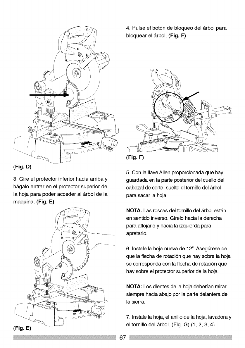
4. Pulse el bot6n de bloqueo del &rbol para
bloquear el arbol. (Fig. F)
(Fig. D)
3. Gire el protector inferior hacia arriba y
h&galo entrar en el protector superior de
la hoja para poder acceder al &rbol de la
maquina. (Fig. E)
(Fig. F)
5. Con la Ilave Allen proporcionada que hay
guardada en la parte posterior del cuello del
cabezal de corte, suelte el tornillo del &rbol
para sacar la hoja.
NOTA: Las roscas del tornillo del &rbol est&n
en sentido inverso. Girelo hacia la derecha
para aflojarlo y hacia la izquierda para
apretarlo.
6. lnstale la hoja nueva de 12". Asegt_rese de
que la flecha de rotaci6n que hay sobre la hoja
se corresponda con la flecha de rotaci6n que
hay sobre el protector superior de la hoja.
NOTA: Los dientes de la hoja deberian mirar
siempre hacia abajo por la parte delantera de
la sierra.
(Fig. E)
7. lnstale la hoja, el anillo de la hoja, lavadora y
el tornillo del &rbol. (Fig. G) (1,2, 3, 4)
67
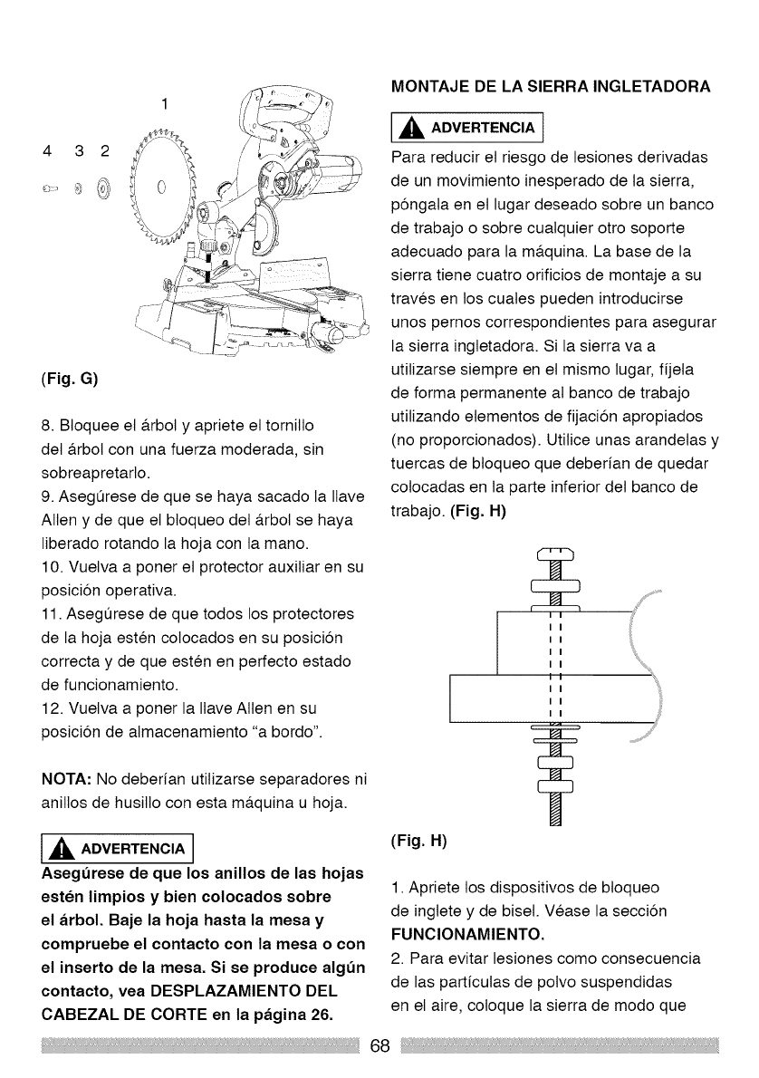
(Fig. G)
8. Bloquee el a.rbol y apriete et tornilto
det a.rbol con una fuerza moderada, sin
sobreapretarto.
9. Asegurese de que se haya sacado la Ilave
Allen y de que el btoqueo det a.rbol se haya
liberado rotando la hoja con la mano.
10. Vuelva a poner et protector auxiliar en su
posicion operativa.
11. Asegurese de que todos los protectores
de la hoja esten colocados en su posicion
correcta y de que esten en perfecto estado
de funcionamiento.
12. Vuelva a poner la Ilave Allen en su
posicion de almacenamiento "a bordo".
NOTA: No deberian utitizarse separadores ni
anitlos de husilto con esta ma.quina u hoja.
,_IL ADVERTENCIA
Asegdrese de que los anillos de las hojas
esten limpios y bien colocados sobre
el arbol. Baje la hoja hasta la mesa y
compruebe el contacto con la mesa o con
el inserto de la mesa. Si se produce algdn
contacto, vea DESPLAZAMIENTO DEL
CABEZAL DE CORTE en la pagina 26.
MONTAJE DE LA SIERRA INGLETADORA
,_1= ADVERTENCIA t
Para reducir et riesgo de lesiones derivadas
de un movimiento inesperado de la sierra,
pongala en et lugar deseado sobre un banco
de trabajo o sobre cuatquier otro soporte
adecuado para la ma.quina. La base de la
sierra tiene cuatro orificios de montaje a su
traves en los cuates pueden introducirse
unos pemos correspondientes para asegurar
la sierra ingletadora. Si la sierra va a
utilizarse siempre en el mismo lugar, fijela
de forma permanente at banco de trabajo
utilizando etementos de fijacion apropiados
(no proporcionados). Utilice unas arandelas y
tuercas de btoqueo que deberian de quedar
colocadas en la parte inferior det banco de
trabajo. (Fig. H)
(Fig. H)
I I
I I
I I
I I
I I
I I
I I
I I
1. Apriete los dispositivos de btoqueo
de ingtete y de biseh Vease la seccion
FUNClONAMIENTO.
2. Para evitar lesiones como consecuencia
de las particutas de polvo suspendidas
en el aire, coloque la sierra de modo que
68
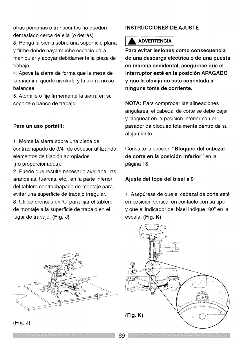
otras personas o transeQntes no queden
demasiado cerca de ella (o detra.s).
3. Ponga la sierra sobre una superficie ptana
y firme donde haya mucho espacio para
manipular y apoyar debidamente la pieza de
trabajo.
4. Apoye la sierra de forma que la mesa de
la ma.quina quede nivetada y la sierra no se
batancee.
5. Atornille o fije firmemente la sierra en su
soporte o banco de trabajo.
Para un uso portatil:
1. Monte la sierra sobre una pieza de
contrachapado de 3/4" de espesor utitizando
etementos de fijaci6n apropiados
(no proporcionados).
2. Puede que resutte necesario aveltanar las
arandelas, tuercas, etc., en la parte inferior
det tabtero contrachapado de montaje para
evitar una superficie de trabajo irregular.
3. Utilice prensas en 'C' para fijar et tabtero
de montaje a la superficie de trabajo en el
lugar de trabajo. (Fig. J)
INSTRUCClONES DE AJUSTE
l_lk ADVERTENCIA I
Para evitar lesiones como consecuencia
de una descarga electrica o de una puesta
en marcha accidental, aseg=3rese que el
interruptor este en la posicibn APAGADO
y que la clavija no este conectada a
ninguna toma de corriente.
NOTA: Para comprobar las alineaciones
angutares, et cabezal de corte se debe bajar
y btoquear en la posici6n inferior con el
pasador de btoqueo totatmente dentro de su
atojamiento.
Consutte la secci6n "Bloqueo del cabezal
de corte en la posicibn inferior" en la
pa.gina 18.
Ajuste del tope del bisel a 0°
1. Asegurese de que el cabezal de corte este
en posici6n vertical en contacto con su tipo
y que el indicador del biset indique "00" en la
escata. (Fig. K)
(Fig. K)
(Fig. J)
69
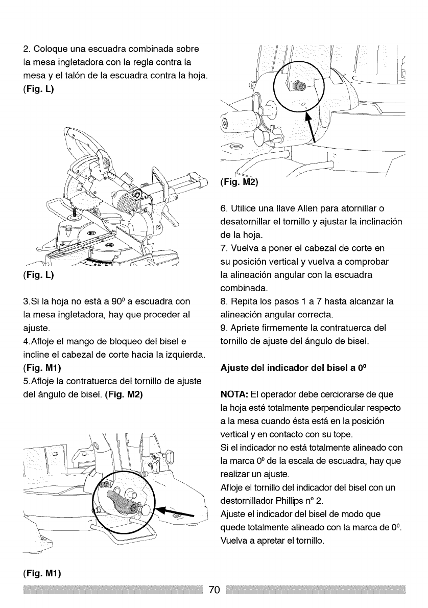
2. Coloque una escuadra combinada sobre
la mesa ingletadora con la regla contra la
mesa y el tal6n de la escuadra contra la hoja.
(Fig. L)
(Fig. L)
3.Si la hoja no est& a 90 oa escuadra con
la mesa ingletadora, hay que proceder al
ajuste.
4.Afloje el mango de bloqueo del bisel e
incline el cabezal de corte hacia la izquierda.
(Fig. M1)
5.Afloje la contratuerca del tornillo de ajuste
del &ngulo de bisel. (Fig. M2)
(Fig. M1)
(Fig. M2)
6. Utilice una Ilave Allen para atornillar o
desatornillar el tornillo y ajustar la inclinaci6n
de la hoja.
7. Vuelva a poner el cabezal de corte en
su posici6n vertical y vuelva a comprobar
la alineaci6n angular con la escuadra
combinada.
8. Repita los pasos 1 a 7 hasta alcanzar la
alineaci6n angular correcta.
9. Apriete firmemente la contratuerca del
tornillo de ajuste del &ngulo de bisel.
Ajuste del indicador del bisel a 0°
NOTA: El operador debe cerciorarse de que
la hoja este totalmente perpendicular respecto
a la mesa cuando esta est& en la posici6n
vertical yen contacto con su tope.
Si el indicador no est& totalmente alineado con
la marca 0° de la escala de escuadra, hay que
realizar un ajuste.
Afloje el tornillo del indicador del bisel con un
destornillador Phillips n° 2.
Ajuste el indicador del bisel de modo que
quede totalmente alineado con la marca de 0°.
Vuelva a apretar el tornillo.
70
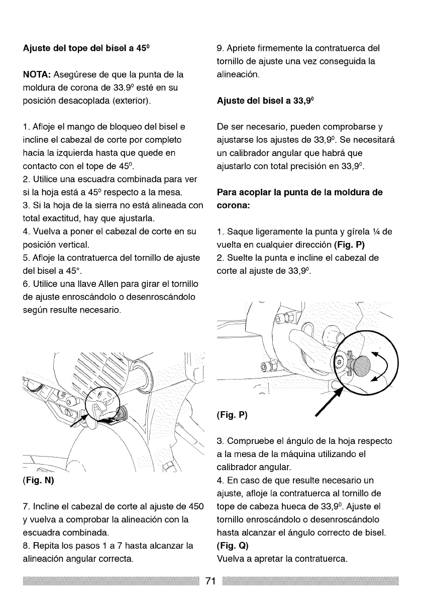
Ajuste del tope del bisel a 450
NOTA: Asegt_rese de que la punta de la
moldura de corona de 33.9 oeste en su
posici6n desacoplada (exterior).
1. Afloje el mango de bloqueo del bisel e
incline el cabezal de corte por completo
hacia la izquierda hasta que quede en
contacto con el tope de 45°.
2. Utilice una escuadra combinada para ver
si la hoja est& a 450 respecto a la mesa.
3. Si la hoja de la sierra no est& alineada con
total exactitud, hay que ajustarla.
4. Vuelva a poner el cabezal de corte en su
posici6n vertical.
5. Afloje la contratuerca del tornillo de ajuste
del bisel a 45°.
6. Utilice una Ilave Allen para girar el tornillo
de ajuste enrosc&ndolo o desenrosc&ndolo
segt_n resulte necesario.
9. Apriete firmemente la contratuerca del
tornillo de ajuste una vez conseguida la
alineaci6n.
Ajuste del bisel a 33,90
De ser necesario, pueden comprobarse y
ajustarse los ajustes de 33,9 °. Se necesitar&
un calibrador angular que habra que
ajustarlo con total precisi6n en 33,9 °.
Para acoplar la punta de la moldura de
corona:
1. Saque ligeramente la punta y girela 1Ade
vuelta en cualquier direcci6n (Fig. P)
2. Suelte la punta e incline el cabezal de
corte al ajuste de 33,9 °.
(Fig. P)
(Fig. N)
7. Incline el cabezal de corte al ajuste de 450
y vuelva a comprobar la alineaci6n con la
escuadra combinada.
8. Repita los pasos 1 a 7 hasta alcanzar la
alineaci6n angular correcta.
3. Compruebe el &ngulo de la hoja respecto
a la mesa de la m&quina utilizando el
calibrador angular.
4. En caso de que resulte necesario un
ajuste, afloje la contratuerca al tornillo de
tope de cabeza hueca de 33,9 °. Ajuste el
tornillo enrosc&ndolo o desenrosc&ndolo
hasta alcanzar el &ngulo correcto de bisel.
(Fig. Q)
Vuelva a apretar la contratuerca.
71
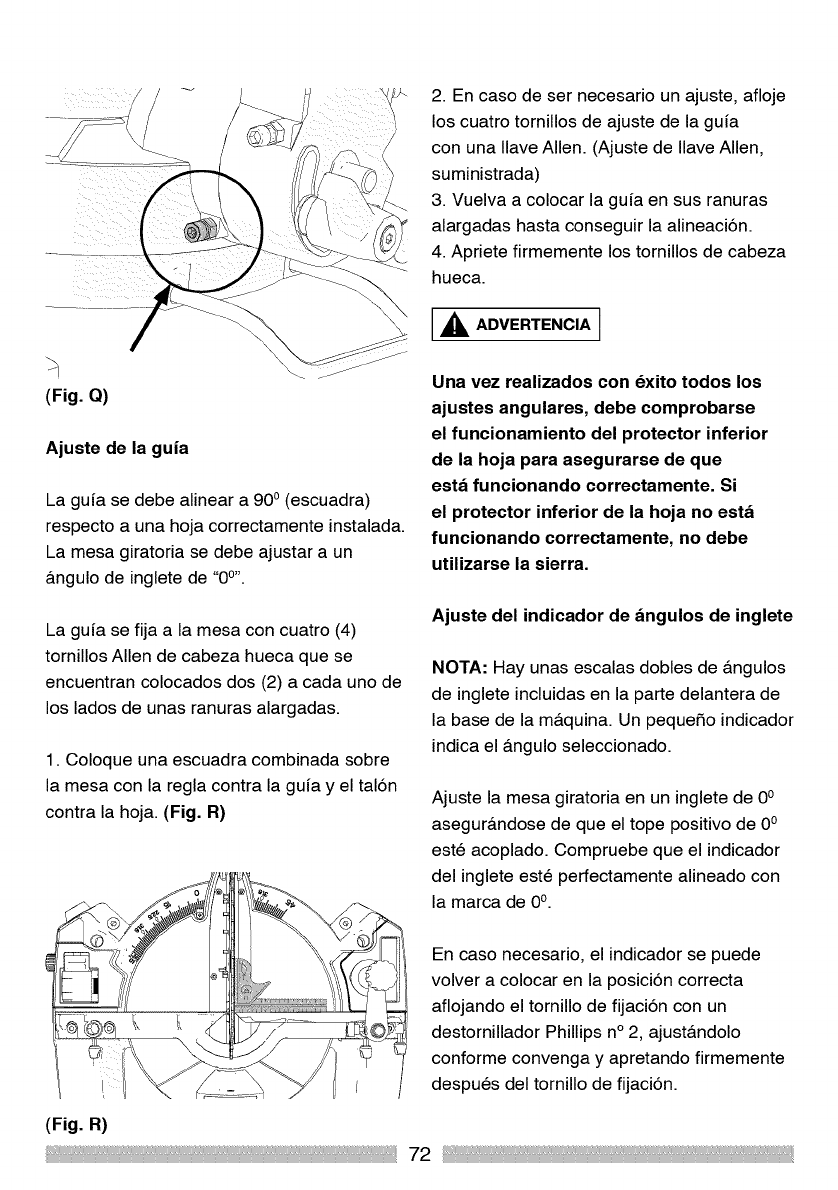
(Fig. Q)
Ajuste de la guia
La gufa se debe alinear a 90 o (escuadra)
respecto a una hoja correctamente instalada.
La mesa giratoria se debe ajustar a un
&ngulo de inglete de '<0°'.
La gufa se fija a la mesa con cuatro (4)
tornillos Allen de cabeza hueca que se
encuentran colocados dos (2) a cada uno de
los lados de unas ranuras alargadas.
1. Coloque una escuadra combinada sobre
la mesa con la regla contra la gufa y el tal6n
contra la hoja. (Fig. R)
2. En caso de ser necesario un ajuste, afloje
los cuatro tornillos de ajuste de la gufa
con una Ilave Allen. (Ajuste de Ilave Allen,
suministrada)
3. Vuelva a colocar la gufa en sus ranuras
alargadas hasta conseguir la alineaci6n.
4. Apriete firmemente los tornillos de cabeza
hueca.
_ADVERTENCIA i
Una vez realizados con dxito todos los
ajustes angulares, debe comprobarse
el funcionamiento del protector inferior
de la hoja para asegurarse de que
esta funcionando correctamente. Si
el protector inferior de la hoja no esta
funcionando correctamente, no debe
utilizarse la sierra.
Ajuste del indicador de angulos de inglete
NOTA: Hay unas escalas dobles de &ngulos
de inglete incluidas en la parte delantera de
la base de la m&quina. Un pequefio indicador
indica el &ngulo seleccionado.
Ajuste la mesa giratoria en un inglete de 0°
asegur&ndose de que el tope positivo de 0°
este acoplado. Compruebe que el indicador
del inglete este 3erfectamente alineado con
la marca de 0°.
En caso necesano, el indicador se puede
volver a colocar en la posici6n correcta
aflojando el tornillo de fijaci6n con un
destornillador Phillips n° 2, ajust&ndolo
conforme convenga y apretando firmemente
despues del tornillo de fijaci6n.
(Fig. R)
72
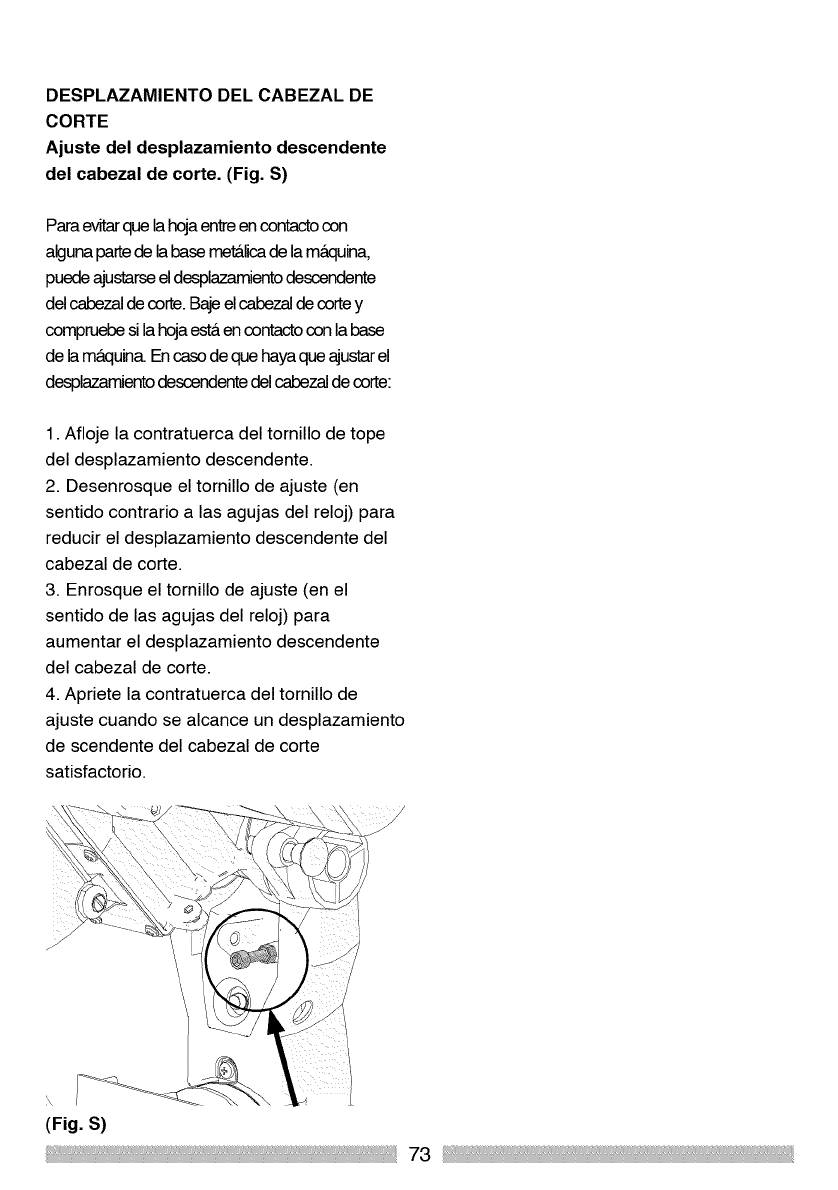
DESPLAZAMIENTO DEL CABEZAL DE
CORTE
Ajuste del desplazamiento descendente
del cabezal de corte. (Fig. S)
Paraevitarque la hojaentreen contactocon
alguna partede labase metalicade la maquina,
puedeajustarseeldesplazamientodescendente
del cabezal de corte. BajeelcabezaJdecorte y
compruebe si la hojaest&en contactocon la base
de la m&quina.En casode que haya que ajustarel
desplazamientodescendente del cabezaJde corte:
1. Afloje la contratuerca del tornillo de tope
del desplazamiento descendente.
2. Desenrosque el tornillo de ajuste (en
sentido contrario alas agujas del reloj) para
reducir el desplazamiento descendente del
cabezal de corte.
3. Enrosque el tornillo de ajuste (en el
sentido de las agujas del reloj) para
aumentar el desplazamiento descendente
del cabezal de corte.
4. Apriete la contratuerca del tornillo de
ajuste cuando se alcance un desplazamiento
de scendente del cabezal de corte
satisfactorio.
× r
(Fig. S)
73
INSTRUCCIONESDESEGURIDAD PARA
EL FUNCIONAMIENTO BASICO DE LA
SIERRA
ANTES DE UTILIZAR LA SIERRA
INGLETADORA
,_ ADVERTENCIA ]
Para evitar errores que podrian causarle
lesiones graves y permanentes, no
enchufe la maquina hasta que haya
completado los pasos siguientes:
Monte y ajuste por completo la sierra
siguiendo las instrucciones. (MONTAJE
Y AJUSTES)
Aprenda et uso y la funcion det
interruptor de gatilto de ENCENDIDO/
APAGADO, la patanca de liberacion
det protector inferior de la hoja, los
protectores superior e inferior de la
hoja, et mango de btoqueo del biset y
et pasador de btoqueo det cabezat de
corte.
Revise y comprenda todas las
instrucciones de seguridad y los
procedimientos de funcionamiento
indicados en este Manual del operador.
Revise la GUJA DE MANTENIMIENTO y
de SOLUClON DE PROBLEMAS de la
sierra ingtetadora.
Para evitar lesiones e incluso la muerte
por descargas etectricas:
Asegurese de no tocar con los
dedos las patillas met&ticas del
enchufe at enchufar o desenchufar
la sierra ingletadora. (REQUlSlTOS
ELI_CTRICOS Y SEGURIDAD)
INSPECClONE LA SIERRA ANTES DE
CADA USO
Desconecte la sierra ingletadora. Para
evitar lesiones como consecuencia
de una puesta en marcha accidental,
desenchufe la sierra antes de realizar
cuatquier ajuste, incluidos la instatacion
y los cambios de hoja.
Compare la direccion de la flecha de
rotacion que hay sobre el protector con
la flecha de direccion que hay sobre la
hoja. Los dientes de la hoja deberian
mirar siempre hacia abajo por la parte
detantera de la sierra.
Apriete el perno del a.rbol.
Compruebe que no haya piezas
dafiadas. Compruebe:
Si hay grietas en la hoja o dientes rotos,
desportitlados o caidos.
La atineacion de las piezas moviles
Cables de alimentacion dafiados
La conexion de las piezas moviles
Los orificios de montaje
El funcionamiento det protector inferior
de la hoja: empuje et cabezal de corte
todo lo que pueda hacia abajo y, a
continuacion, deje que suba hasta
que se pare. El protector inferior de la
hoja deberia de cerrarse por completo
rodeando la hoja. Siga las instrucciones
de la GUiA DE SOLUCION DE
PROBLEMAS para la reatizacion de
cualquier ajuste necesario.
Cuatquier otra condicion que pudiera
afectar la manera de funcionar de la
sierra ingtetadora.
Mantenga todos los protectores
en su lugar correspondiente, en
perfecto estado de funcionamiento y
74
correctamente ajustados. Si atguna
de las piezas de la sierra ingletadora
fattara, estuviera dobtada, dafiada o rota
de cuatquier manera, o si no funcionaran
las piezas electricas APAGUE la sierra y
desenchufela.
Reemptace las piezas dobtadas,
dafiadas, perdidas o defectuosas antes
de volver a utilizar la sierra de nuevo.
Mantenga las herramientas con cuidado.
Mantenga la sierra limpia para que su
funcionamiento sea mejor y ma.s seguro.
Siga las instrucciones de lubricacion. No
lubrique ta hoja mientras gira.
Retire todas las herramientas de ajuste
de la sierra antes de ENCENDERLA.
Para evitar lesiones por obstrucciones,
deslizamientos o desprendimientos
de las piezas, utitice Qnicamente los
accesorios recomendados.
Compruebe la bolsa det polvo antes de
empezar a trabajar. Vacie la botsa si
esta. Ilena ma.s de la mitad.
ACCESORIOS DISPONIBLES
Consutte la seccion ACCESORIOS y
ACOPLAMIENTOS de este Manual
det operador para obtener informacion
acerca de los accesorios disponibtes.
Siga las instrucciones que se incluyen
con el accesorio. El uso de accesorios
inadecuados puede impticar riesgos de
lesiones personates.
Elija la hoja de 12" de dia.metro
apropiada para el material y el tipo de
corte que planea realizar. No utilice
hojas con un ancho de corte fino.
Asegurese de que la hoja este afitada,
no este dafiada y este bien instalada.
Con ta sierra desenchufada, empuje et
cabezal de corte todo Io que pueda. Gire
a mano la hoja y compruebe la holgura.
Incline et cabezal de corte a un _tnguto
de biset de 450 y repita la prueba.
Asegurese de que los anitlos de la hoja
y det a.rbot esten limpios.
Asegurese de que todas tas prensas y
torniltos de btoqueo esten apretados y
de que no haya un juego excesivo en
ninguna de las piezas.
MANTEGA LIMPIA EL AREA DE TRABAJO
I,_ ADVERTENCIA I
Las zonas y los bancos de trabajo
desordenados facilitan los accidentes.
Para evitar quemaduras o cualquier otro
daSo causado pot el fuego, nunca utilice
la sierra ingletadora cerca de liquidos,
vapores o gases inflamables.
Planifique de antemano como
protegerse los ojos, las manos, la cara y
los oidos.
Conozca la sierra ingletadora.
Lea y comprenda et Manual del
operador y las etiquetas pegadas a la
herramienta. Aprenda su aplicacion y
sus timitaciones, asi como los petigros
potenciates especificos propios de esta
herramienta. Para evitar lesiones como
consecuencia de un contacto accidental
con las piezas movites, no disponga,
monte o prepare et trabajo sobre la
sierra ingletadora mientras haya piezas
en movimiento.
Para evitar una puesta en marcha
accidental, asegurese de que et
interruptor de gatilto este en la posicion
75
APAGADO antes de enchufar la
sierra ingtetadora en una fuente de
atimentaci6n.
PLANIFIQUE EL TRABAJO
Utilice la herramienta adecuada. No
permita que alguna herramienta o
acoplamiento reatice un trabajo para
et que no ha sido dise_ado. Utilice una
herramienta diferente para cualquier
pieza que no pueda mantenerse sujeta
en una posicion bien agarrada y fija.
,_ PREOAUOI()N ]
Esta maquina no ha sido diseSada
para eortar productos de albaSileria ni
productos que eontienen materiales tipo
asbesto. Utilice la sierra ingletadora para
eortar madera y produetos abase de
madera. El resto de los materiales pueden
romperse, quedarse unidos ala hoja
u originar otros peligros. Inspeccione
la pieza de trabajo para ver si contiene
algen material prohibido antes de
empezar a eortar. Quite todos los elavos,
tornillos u otros objetos extraSos de este
tipo antes de empezar a eortar.
UTILICE UNA VESTIMENTA SEGURA
O Cualquier herramienta
electrica puede lanzar objetos
extraSos a los ojos. Esto
puede ocasionar un daSo
permanente en los ojos. Las gafas de uso
diario sblo tienen lentes resistentes a los
impactos y no son gafas de seguridad.
Las gafas o lentes que no cumplen la
ANSI Z87.1 pueden ocasionarle graves
lesiones si se rompen.
No utilice ropa suetta, guantes, corbatas
ni alhajas (anillos, retojes, etc.). Pueden
atascarse y atraerlo hacia las piezas
m6viles.
Utilice calzado antideslizante.
Si tiene et pelo largo, recojaseto.
Arrema.nguese las mangas largas hasta
arriba del codo.
Los nivetes de ruido vat[an
considerabtemente. Para evitar un
posibte da5o auditivo, protejase
los oidos at utilizar cuatquier sierra
ingletadora.
Cuando realice trabajos que generen
mucho polvo, utilice una mascarilta
contra et potvo adema.s de gafas de
seguridad.
INSPECClONE LA PIEZA DE TRABAJO
Compruebe la pieza de trabajo y asegurese
de que no contenga materiales prohibidos
tales como materiales de atbaRileria
o asbesto. Planifique la secuencia de
operaciones que desea reatizar para
asegurarse de que la pieza de trabajo estara.
en todo momento bien fijada a la mesa de
la sierra. Evite las piezas pequeRas ya que
son dif[ciles de agarrar de forma segura.
Evite operaciones y posiciones de las manos
inc6modas donde un resbaton repentino
podria hacer que los dedos o la mano se
muevan hacia la hoja.
Para evitar graves lesiones pot un corte con
la hoja, no extienda NUNCA et brazo o la
mano de modo que quede en la trayectoria
de ta hoja.
Mantenga et equilibrio y et apoyo correcto de
los pies. Cotoquese a un lado de modo que
76
la cara y el cuerpo queden fuera de la linea
de un posibte contragotpe. NUNCA extienda
et brazo o la mano de modo que quede "en
linea" con la trayectoria de corte de la hoja.
Los cortes a putso son una de las causas
principates de accidentes y jama.s deben
reatizarse.
Asegurese de que la pieza de trabajo
siempre quede firmemente en contacto
con la guia y que, siempre que se
pueda, quede fijada a la mensa con la
prensa de sujecion.
La mesa debe estar limpia y sin serrin,
etc., antes de fijar la pieza de trabajo en
la posicion correspondiente.
Asegurese de que el material "cortado"
pueda moverse libremente hacia los
lados aleja.ndose de la hoja una vez
reatizado et corte. Asegurese de que la
pieza "cortada" no se pueda "atascar" en
cuatquier otra parte de la ma.quina.
Asegure siempre la pieza de trabajo.
Siempre que pueda, utilice la prensa o
prensas de sujecion.
No utilice esta sierra para cortar piezas
pequefias. La pieza de trabajo que va
a cortar sera. demasiado pequefia si
at sujetarla sus manos o sus dedos
quedan a menos de 6-3/8" de distancia
de la hoja de la sierra.
Mantenga las manos y los dedos fuera
de la "zona sin manos" marcada con
pictogramas en la mesa de la sierra.
EXTREME LAS PRECAUClONES CON
LAS PIEZAS DE TRABAJO GRANDES O
CON UNA FORMA IRREGULAR
Utilice soportes adicionates tales como
cabaltetes o soportes con roditlos, etc.,
ajustados de modo que queden a la misma
attura que la mesa de la sierra para evitar
que las piezas grandes se vuetquen o se
tuerzan durante el corte.
No utitice a otra persona para agarrar o
soportar una pieza de trabajo grande o
con una forma irregular, o para ayudar a
atimentar et material en ta sierra.
At cortar piezas de trabajo con una forma
irregular, ptanifique la secuencia de
operaciones para asegurarse de reducir at
ma.ximo la posibitidad de que la pieza se
quede unida a la hoja o de contragotpes.
Sujete bien los materiates redondos o
tubulares de modo que queden bien
asegurados a la mesa de la sierra. Utilice
una prensa de sujecion disefiada para la
sujecion de este tipo de materiates.
I,_ ADVERTENCIA I
No permita que la familiarizacibn con la
sierra ingletadora por un uso frecuente de
la misma de lugar a errores por descuidos.
Un descuido de una fraccibn de segundo
es suficiente para que se produzcan
graves lesiones. Antes de cortar, si la
sierra hace un ruido desconocido o vibra,
parela inmediatamente. APAGUE la sierra.
Desenchufe la sierra. No vuelva a iniciar las
operaciones hasta que se haya descubierto
y solucionado el problema.
77
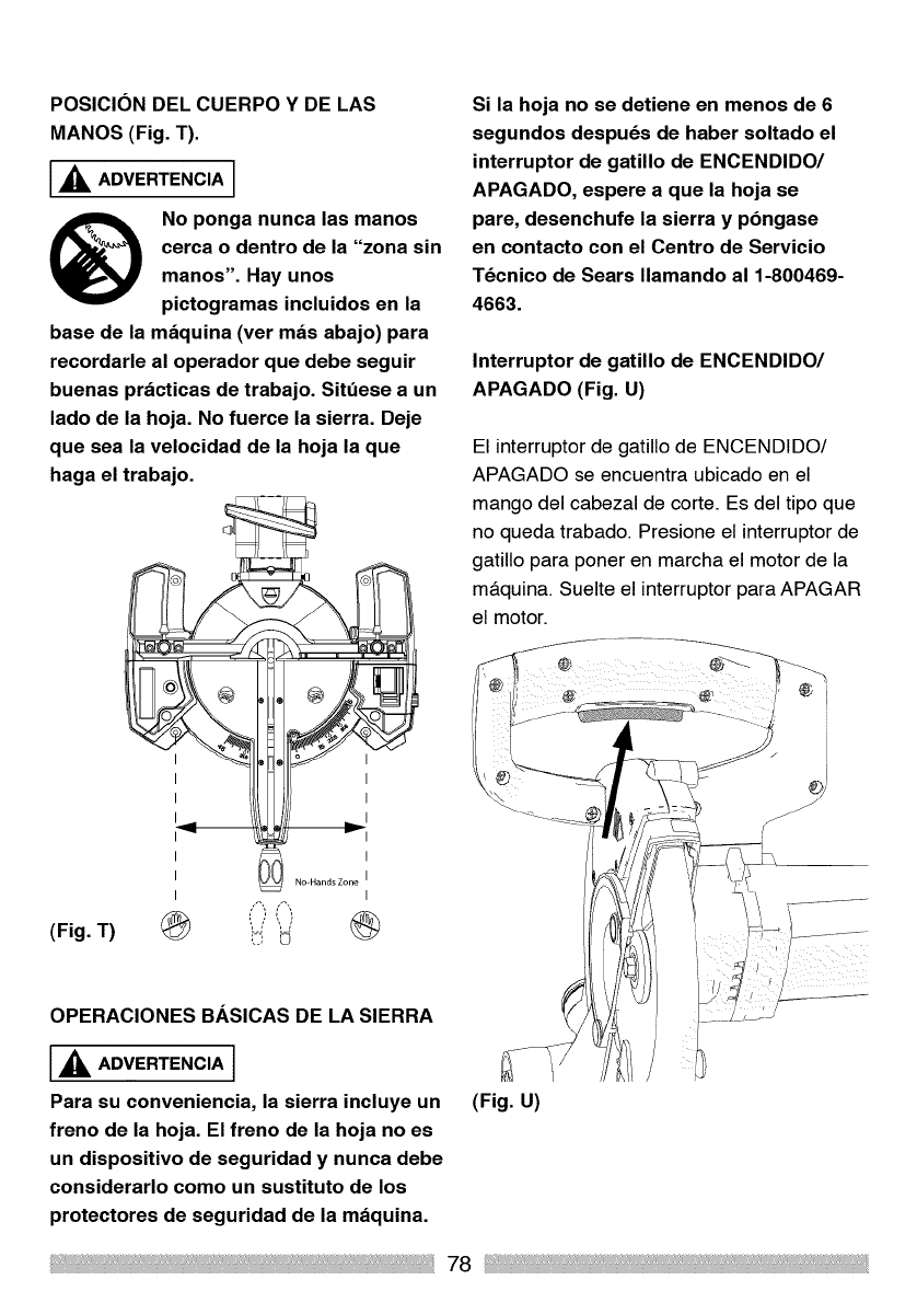
POSICION DEL CUERPO Y DE LAS
MANOS (Fig. T).
_lk ADVERTENCIA
No ponga nunca las manos
cerca o dentro de la "zona sin
manos". Hay unos
pictogramas incluidos en la
base de la maquina (ver mas abajo) para
recordarle al operador que debe seguir
buenas practicas de trabajo. Sit_ese a un
lado de la hoja. No fuerce la sierra. Deje
que sea la velocidad de la hoja la que
haga el trabajo.
Si la hoja no se detiene en menos de 6
segundos despu6s de haber soltado el
interruptor de gatillo de ENCENDIDO/
APAGADO, espere a que la hoja se
pare, desenchufe la sierra y pbngase
en contacto con el Centro de Servicio
T_cnico de Sears Ilamando al 1-800469-
4663.
Interruptor de gatillo de ENCENDIDO/
APAGADO (Fig. U)
El interruptor de gatillo de ENCENDIDO/
APAGADO se encuentra ubicado en el
mango del cabezal de corte. Es del tipo que
no queda trabado. Presione el interruptor de
gatillo para poner en marcha el motor de la
m&quina. Suelte el interruptor para APAGAR
el motor.
/ ', ?
(Fig. T) (_ i:-" _ (_
OPERACIONES BASICAS DE LA SIERRA
'_I= ADVERTENClA I
Para su conveniencia, la sierra incluye un
freno de la hoja. El freno de la hoja no es
un dispositivo de seguridad y nunca debe
considerarlo como un sustituto de los
protectores de seguridad de la maquina.
/
(Fig. U)
78
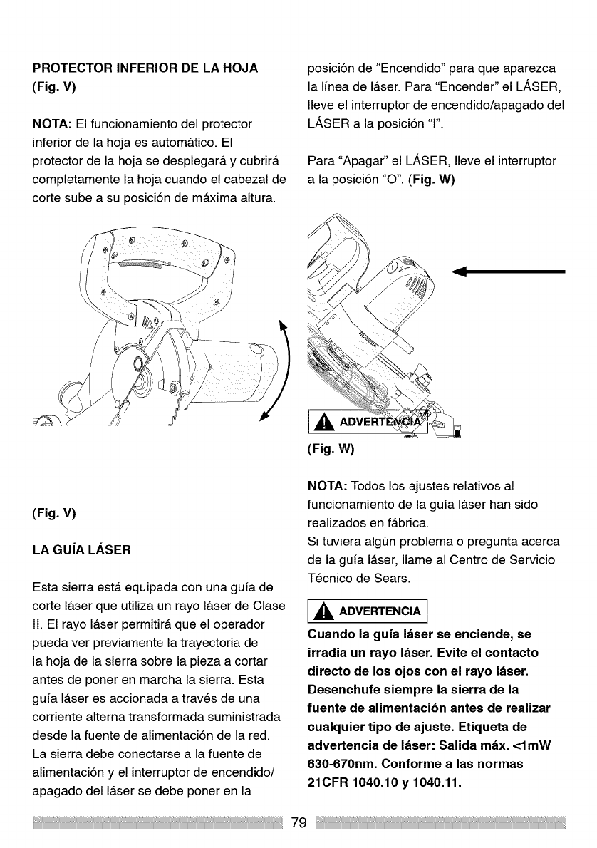
PROTECTOR INFERIOR DE LA HOJA
(Fig. V)
NOTA: El funcionamiento del protector
inferior de la hoja es autom&tico. El
protector de la hoja se desplegara y cubrira
completamente la hoja cuando el cabezal de
corte sube a su posici6n de m&xima altura.
posici6n de "Encendido" para que aparezca
la linea de I&ser. Para "Encender" el LASER,
Ileve el interruptor de encendido/apagado del
LASER a la posici6n 'T'.
Para "Apagar" el LASER, Ileve el interruptor
a la posici6n "O'. (Fig. W)
(Fig. V)
LA GUiA LASER
Esta sierra est& equipada con una guia de
corte I&ser que utiliza un rayo I&ser de Clase
11.El rayo I&ser permitir& que el operador
pueda ver previamente la trayectoria de
la hoja de la sierra sobre la pieza a cortar
antes de poner en marcha la sierra. Esta
guia I&ser es accionada a traves de una
corriente alterna transformada suministrada
desde la fuente de alimentaci6n de la red.
La sierra debe conectarse a la fuente de
alimentaci6n y el interruptor de encendido/
apagado del I&ser se debe poner en la
NOTA: Todos los ajustes relativos al
funcionamiento de la guia I&ser han sido
realizados en f&brica.
Si tuviera algen problema o pregunta acerca
de la guia I&ser, Ilame al Centro de Servicio
Tecnico de Sears.
_ADVERTENCIA i
Cuando la guia laser se enciende, se
irradia un rayo laser. Evite el contacto
directo de los ojos con el rayo laser.
Desenchufe siempre la sierra de la
fuente de alimentacibn antes de realizar
cualquier tipo de ajuste. Etiqueta de
advertencia de laser: Salida max. <lmW
630-670nm. Conforme a las normas
21CFR 1040.10 y 1040.11.
79
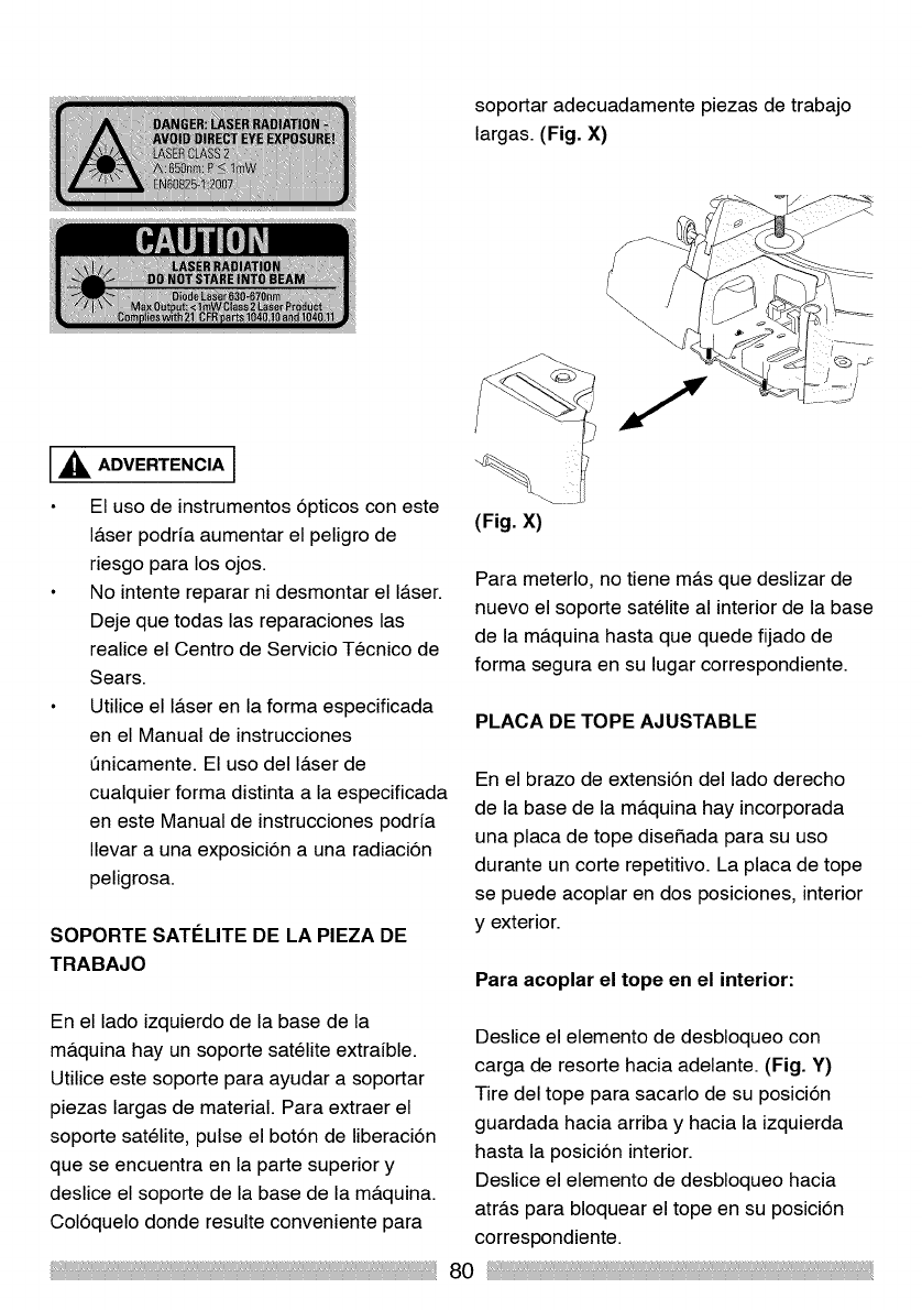
soportar adecuadamente piezas de trabajo
largas. (Fig. X)
_IL ADVERTENCIA ]
El uso de instrumentos 6pticos con este
I&ser podrfa aumentar el peligro de
riesgo para los ojos.
No intente reparar ni desmontar el I&ser.
Deje que todas las reparaciones las
realice el Centro de Servicio Tecnico de
Sears.
Utilice el I&ser en la forma especificada
en el Manual de instrucciones
t_nicamente. El uso del I&ser de
cualquier forma distinta a la especificada
en este Manual de instrucciones podrfa
Ilevar a una exposici6n a una radiaci6n
peligrosa.
SOPORTE SATI_LITE DE LA PIEZA DE
TRABAJO
(Fig. X)
Para meterlo, no tiene m&s que deslizar de
nuevo el soporte satelite al interior de la base
de la m&quina hasta que quede fijado de
forma segura en su lugar correspondiente.
PLACA DE TOPE AJUSTABLE
En el brazo de extensi6n del lado derecho
de la base de la m&quina hay incorporada
una placa de tope dise_ada para su uso
durante un corte repetitivo. La placa de tope
se puede acoplar en dos posiciones, interior
y exterior.
Para acoplar el tope en el interior:
En el lado izquierdo de la base de la
m&quina hay un soporte satelite extrafble.
Utilice este soporte para ayudar a soportar
piezas largas de material. Para extraer el
soporte satelite, pulse el bot6n de liberaci6n
que se encuentra en la parte superior y
deslice el soporte de la base de la m&quina.
Col6quelo donde resulte conveniente para
Deslice el elemento de desbloqueo con
carga de resorte hacia adelante. (Fig. Y)
Tire del tope para sacarlo de su posici6n
guardada hacia arriba y hacia la izquierda
hasta la posici6n interior.
Deslice el elemento de desbloqueo hacia
atr&s para bloquear el tope en su posici6n
correspondiente.
80
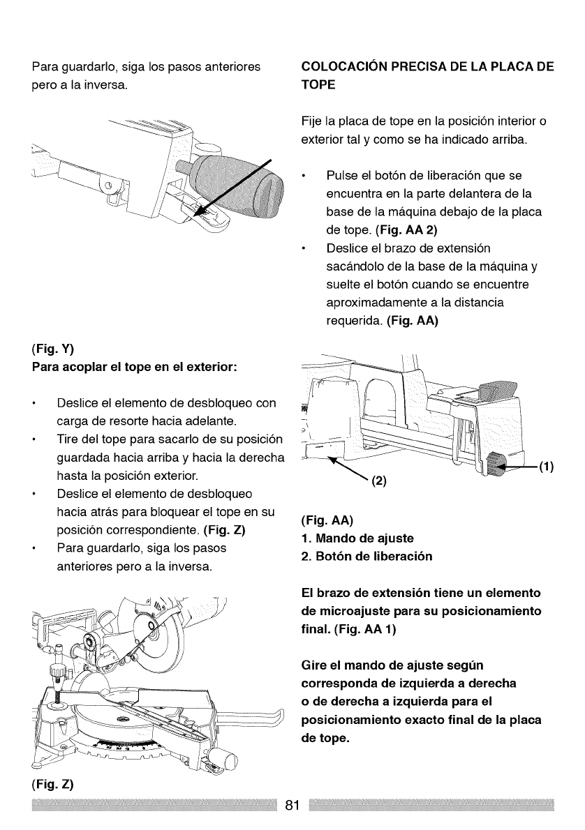
Para guardarlo, siga los pasos anteriores
pero a la inversa.
(Fig. Y)
Para acoplar el tope en el exterior:
Deslice el elemento de desbloqueo con
carga de resorte hacia adelante.
Tire del tope para sacarlo de su posici6n
guardada hacia arriba y hacia la derecha
hasta la posici6n exterior.
Deslice el elemento de desbloqueo
hacia atr&s para bloquear el tope en su
posici6n correspondiente. (Fig. Z)
Para guardarlo, siga los pasos
anteriores pero a la inversa.
COLOCACION PRECISA DE LA PLACA DE
TOPE
Fije la placa de tope en la posici6n interior o
exterior tal y como se ha indicado arriba.
Pulse el bot6n de liberaci6n que se
encuentra en la parte delantera de la
base de la m&quina debajo de la placa
de tope. (Fig. AA 2)
Deslice el brazo de extensi6n
sac&ndolo de la base de la m&quina y
suelte el bot6n cuando se encuentre
aproximadamente a la distancia
requerida. (Fig. AA)
(2)
(Fig. AA)
1. Mando de ajuste
2. Botbn de liberacibn
El brazo de extensibn tiene un elemento
de microajuste para su posicionamiento
final. (Fig. AA 1)
Gire el mando de ajuste segt_n
corresponda de izquierda a derecha
o de derecha a izquierda para el
posicionamiento exacto final de la placa
de tope.
(Fig. z)
81
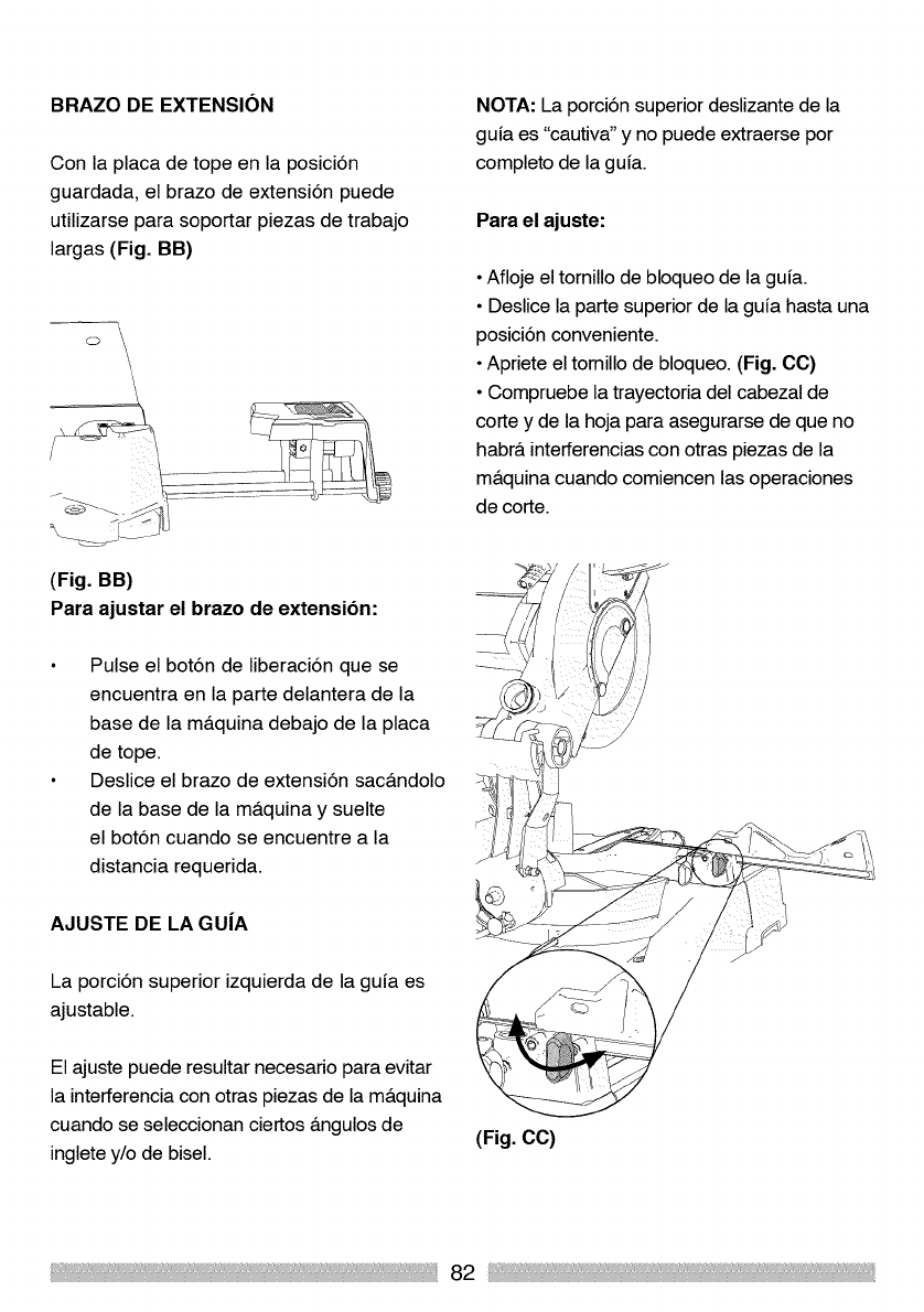
BRAZO DE EXTENSION
Con la placa de tope en la posici6n
guardada, el brazo de extensi6n puede
utilizarse para soportar piezas de trabajo
largas (Fig. BB)
°\ \
NOTA: La porci6n superior deslizante de la
guia es "cautiva" y no puede extraerse por
completo de la guia.
Para el ajuste:
•Afloje el tornillo de bloqueo de la guia.
• Deslice la parte superior de la gufa hasta una
posici6n conveniente.
•Apriete el tornillo de bloqueo. (Fig. CC)
• Compruebe la trayectoria del cabezal de
corte y de la hoja para asegurarse de que no
habr& interferencias con otras piezas de la
m&quina cuando comiencen las operaciones
de corte.
(Fig. BB)
Para ajustar el brazo de extensibn:
Pulse el bot6n de liberaci6n que se
encuentra en la parte delantera de la
base de la m&quina debajo de la placa
de tope.
Deslice el brazo de extensi6n sac&ndolo
de la base de la m&quina y suelte
el bot6n cuando se encuentre a la
distancia requerida.
AJUSTE DE LA GU|A
La porci6n superior izquierda de la gufa es
ajustable.
El ajuste puede resultar necesario para evitar
la interferencia con otras piezas de la m&quina
cuando se seleccionan ciertos &ngulos de
inglete y/o de bisel. (Fig. CC)
82
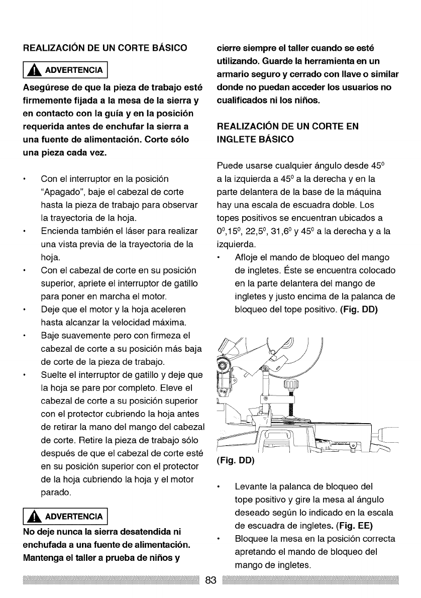
REALIZACION DE UN CORTE BASICO
_ADVERTENCIA
Asegdrese de que la pieza de trabajo estd
firmemente fijada a la mesa de la sierra y
en contacto con la guia y en la posicibn
requerida antes de enchufar la sierra a
una fuente de alimentacibn. Corte sblo
una pieza cada vez.
Con el interruptor en la posici6n
"Apagado", baje el cabezal de corte
hasta la pieza de trabajo para observar
la trayectoria de la hoja.
Encienda tambien el I&ser para realizar
una vista previa de la trayectoria de la
hoja.
Con el cabezal de corte en su posici6n
superior, apriete el interruptor de gatillo
para poner en marcha el motor.
Deje que el motor y la hoja aceleren
hasta alcanzar la velocidad m&xima.
Baje suavemente pero con firmeza el
cabezal de corte a su posici6n m&s baja
de corte de la pieza de trabajo.
Suelte el interruptor de gatillo y deje que
la hoja se pare por completo. Eleve el
cabezal de corte a su posici6n superior
con el protector cubriendo la hoja antes
de retirar la mano del mango del cabezal
de corte. Retire la pieza de trabajo s61o
despues de que el cabezal de corte este
en su posici6n superior con el protector
de la hoja cubriendo la hoja y el motor
parado.
,_ ADVERTENCIA
No deje nunca la sierra desatendida ni
enchufada a una fuente de alimentacibn.
Mantenga el taller a prueba de niSos y
cierre siempre el taller cuando se estd
utilizando. Guarde la herramienta en un
armario seguro y cerrado con Ilave o similar
donde no puedan acceder los usuarios no
cualificados ni los niSos.
REALIZACION DE UN CORTE EN
INGLETE BASICO
Puede usarse cualquier angulo desde 45o
a la izquierda a 45 oa la derecha yen la
parte delantera de la base de la m&quina
hay una escala de escuadra doble. Los
topes positivos se encuentran ubicados a
0°,15 °, 22,5 °, 31,6 ° y 450 a la derecha y a la
izquierda.
Afloje el mando de bloqueo del mango
de ingletes. I_ste se encuentra colocado
en la parte delantera del mango de
ingletes y justo encima de la palanca de
bloqueo del tope positivo. (Fig. DD)
(Fig. DD)
Levante la palanca de bloqueo del
tope positivo y gire la mesa al angulo
deseado segQn Io indicado en la escala
de escuadra de ingletes. (Fig. EE)
Bloquee la mesa en la posici6n correcta
apretando el mando de bloqueo del
mango de ingletes.
83
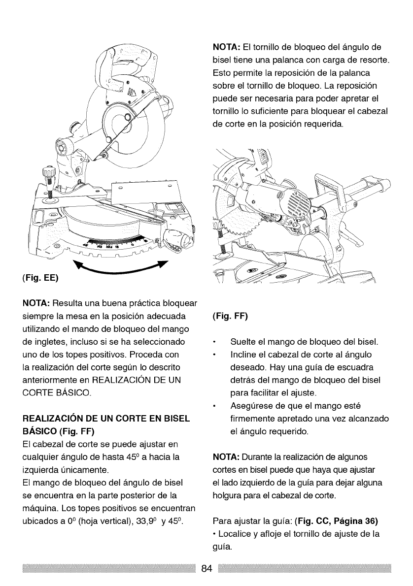
NOTA: El tornillo de bloqueo del &ngulo de
bisel tiene una palanca con carga de resorte.
Esto permite la reposici6n de la palanca
sobre el tornillo de bloqueo. La reposici6n
puede ser necesaria para poder apretar el
tornillo Io suficiente para bloquear el cabezal
de corte en la posici6n requerida.
(Fig. EE)
NOTA: Resulta una buena pr&ctica bloquear
siempre la mesa en la posici6n adecuada
utilizando el mando de bloqueo del mango
de ingletes, incluso si se ha seleccionado
uno de los topes positivos. Proceda con
la realizaci6n del corte segt_n Io descrito
anteriormente en REALIZACION DE UN
CORTE BASICO.
REALIZACION DE UN CORTE EN BISEL
BASICO (Fig. FF)
El cabezal de corte se puede ajustar en
cualquier &ngulo de hasta 450 a hacia la
izquierda t_nicamente.
El mango de bloqueo del &ngulo de bisel
se encuentra en la parte posterior de la
m&quina. Los topes positivos se encuentran
ubicados a 0° (hoja vertical), 33,90 y 45°.
(Fig. FF)
Suelte el mango de bloqueo del bisel.
Incline el cabezal de corte al &ngulo
deseado. Hay una gufa de escuadra
detr&s del mango de bloqueo del bisel
para facilitar el ajuste.
Asegt_rese de que el mango este
firmemente apretado una vez alcanzado
el &ngulo requerido.
NOTA: Durante la realizaci6n de algunos
cortes en bisel puede que haya que ajustar
el lado izquierdo de la guia para dejar alguna
holgura para el cabezal de corte.
Para ajustar la gufa: (Fig. CC, Pagina 36)
•Localice y afloje el tornillo de ajuste de la
gufa.
84
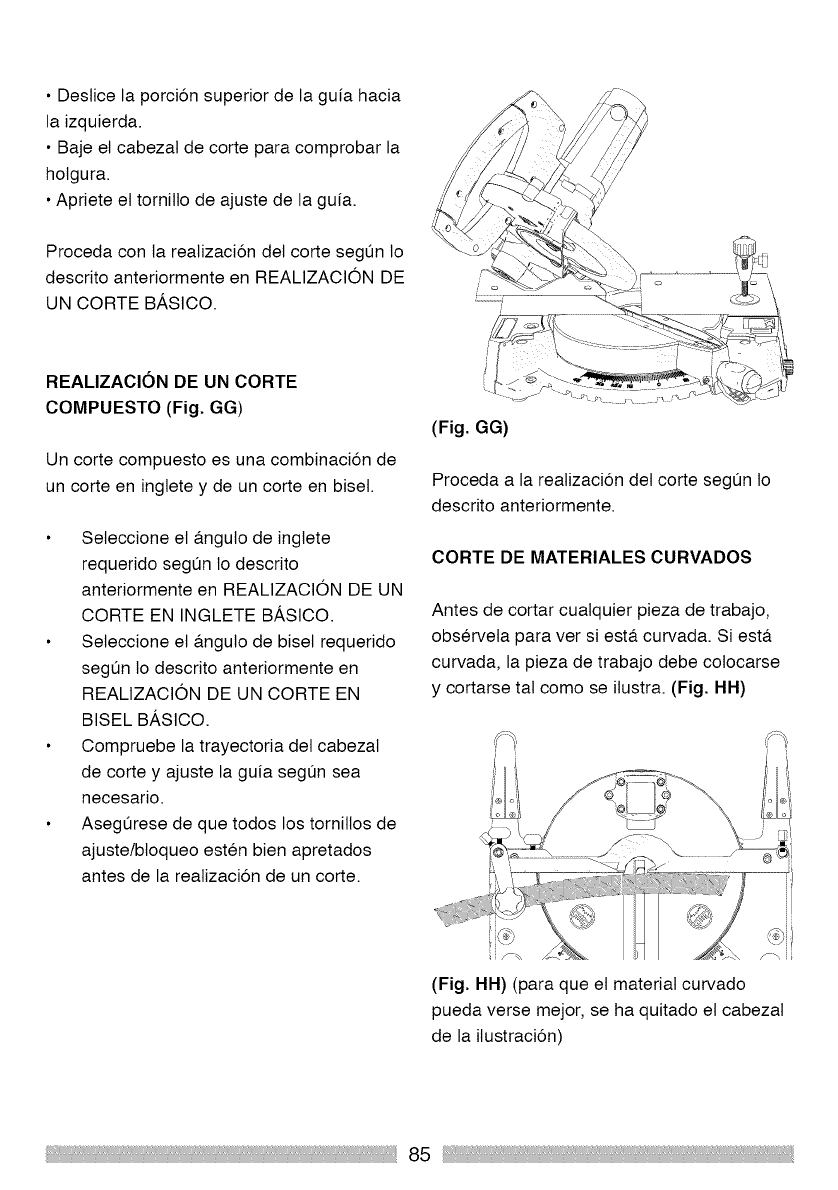
• Destice la porcion superior de la guia hacia
la izquierda.
• Baje el cabezat de corte para comprobar la
holgura.
• Apriete et tornitlo de ajuste de la guia.
Proceda con la reatizacion del corte segun Io
descrito anteriormente en REALIZACION DE
UN CORTE BASlCO.
REALIZACION DE UN CORTE
COMPUESTO (Fig. GG)
Un corte compuesto es una combinacion de
un corte en inglete y de un corte en biset.
Seleccione et a.nguto de inglete
requerido segun lo descrito
anteriormente en REALIZACION DE UN
CORTE EN INGLETE BASlCO.
Seleccione et a.nguto de biset requerido
segun Io descrito anteriormente en
REALIZACION DE UN CORTE EN
BISEL BASlCO.
Compruebe la trayectoria del cabezat
de corte y ajuste la guia segun sea
necesario.
Asegurese de que todos los tornitlos de
ajuste/btoqueo esten bien apretados
antes de la reatizacion de un corte.
................7
(Fig. GG)
Proceda a la reatizacion det corte segun Io
descrito anteriormente.
CORTE DE MATERIALES CURVADOS
Antes de cortar cuatquier pieza de trabajo,
observeta para ver si est& curvada. Si est&
curvada, la pieza de trabajo debe cotocarse
y cortarse tat como se ilustra. (Fig. HH)
(Fig. HH) (para que et material curvado
pueda verse mejor, se ha quitado et cabezat
de la ilustracion)
85
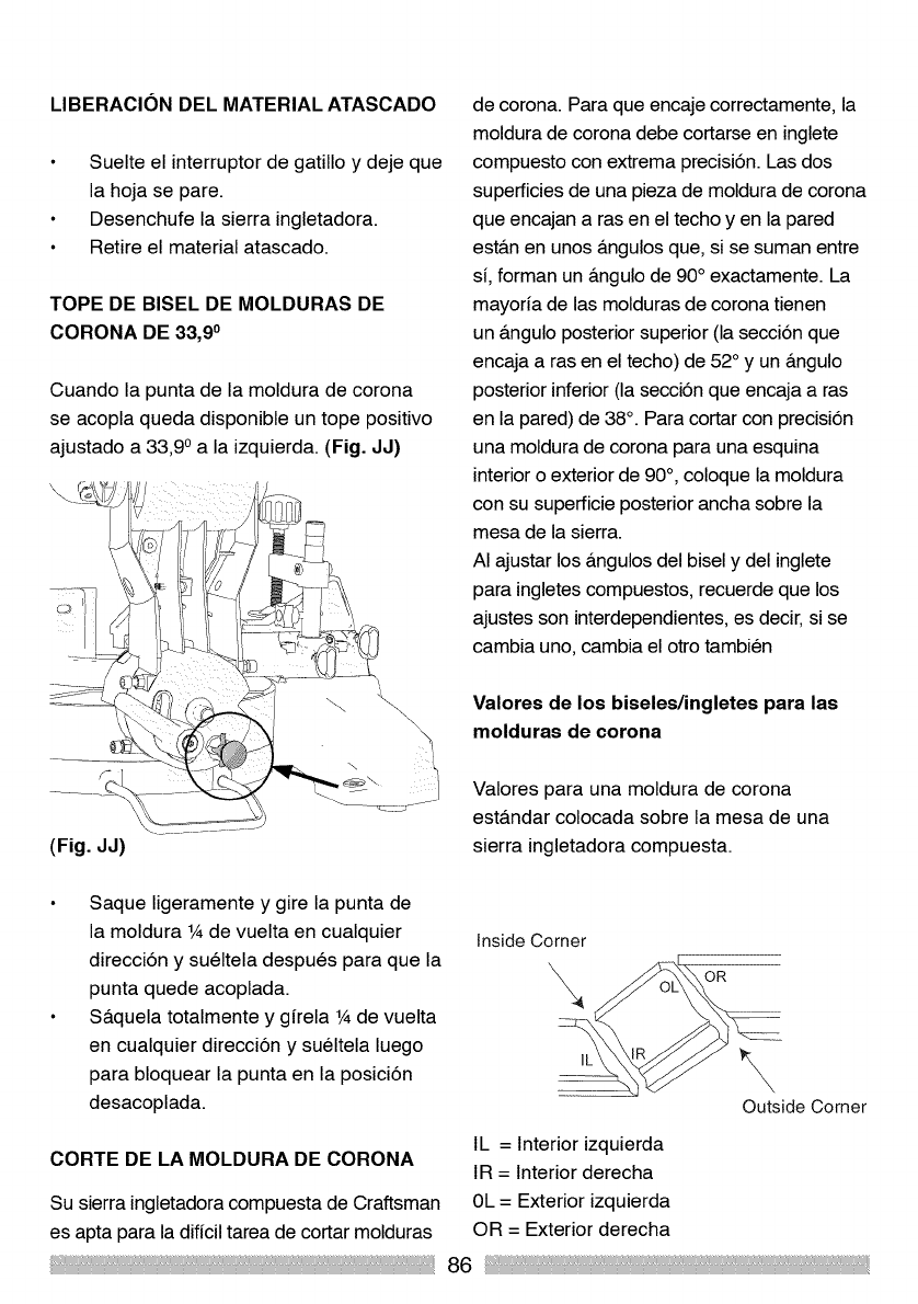
LIBERACION DEL MATERIAL ATASCADO
Suelte el interruptor de gatillo y deje que
la hoja se pare.
Desenchufe la sierra ingletadora.
Retire el material atascado.
TOPE DE BISEL DE MOLDURAS DE
CORONA DE 33,90
Cuando la punta de la moldura de corona
se acopla queda disponible un tope positivo
ajustado a 33,9 o a la izquierda. (Fig. JJ)
de corona. Para que encaje correctamente, la
moldura de corona debe cortarse en inglete
compuesto con extrema precisi6n. Las dos
superficies de una pieza de moldura de corona
que encajan a ras en el techo yen la pared
est&n en unos &ngulos que, si se suman entre
si, forman un &ngulo de 90° exactamente. La
mayoria de las molduras de corona tienen
un &ngulo posterior superior (la secci6n que
encaja a ras en el techo) de 52 ° y un &ngulo
posterior inferior (la secci6n que encaja a ras
en la pared) de 38 °. Para cortar con precisi6n
una moldura de corona para una esquina
interior o exterior de 90°, coloque la moldura
con su superficie posterior ancha sobre la
mesa de la sierra.
AI ajustar los &ngulos del bisel y del inglete
para ingletes compuestos, recuerde que los
ajustes son interdependientes, es decir, si se
cambia uno, cambia el otro tambien
Valores de los biseles/ingletes para las
molduras de corona
(Fig. JJ)
Valores para una moldura de corona
est&ndar colocada sobre la mesa de una
sierra ingletadora compuesta.
Saque ligeramente y gire la punta de
la moldura 1Ade vuelta en cualquier
direcci6n y sueltela despues para que la
punta quede acoplada.
S&quela totalmente y girela 1Ade vuelta
en cualquier direcci6n y sueltela luego
para bloquear la punta en la posici6n
desacoplada.
Inside Corner
\OR
\
Outside Corner
CORTE DE LA MOLDURA DE CORONA IL = Interior izquierda
IR = Interior derecha
Su sierra ingletadora compuesta de Craftsman 0L = Exterior izquierda
es apta para la dificil tarea de cortar molduras OR = Exterior derecha
86
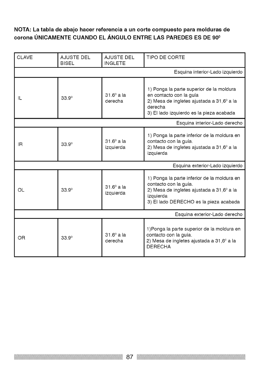
NOTA: La tabla de abajo hacer referencia a un corte compuesto para molduras de
corona UNICAMENTE CUANDO EL ANGULO ENTRE LAS PAREDES ES DE 900
CLAVE AJUSTE DEL AJUSTE DEL TIPO DE CORTE
BISEL INGLETE
Esquina interior-Lado izquierdo
IL
IR
OL
OR
33.9 o 31.6 ° a la
derecha
1) Ponga la parte superior de la moldura
en contacto con la guia
2) Mesa de ingletes ajustada a 31,60 a la
derecha
3) El lado izquierdo es la pieza acabada
Esquina interior-Lado derecho
33.9 o 31.6 o a la
izquierda
1) Ponga la parte inferior de la moldura en
contacto con la guia.
2) Mesa de ingletes ajustada a 31,60 a la
izquierda
Esquina exterior-Lado izquierdo
33.9 o 31.6 o a la
izquierda
1) Ponga la parte inferior de la moldura en
contacto con la guia.
2) Mesa de ingletes ajustada a 31,60 a la
izquierda
3) El lado DERECHO es la pieza acabada
Esquina exterior-Lado derecho
33.9 o 31.6 o a la
derecha
1)Ponga la parte superior de la moldura en
contacto con la guia.
2) Mesa de ingletes ajustada a 31,60 a la
DERECHA
87
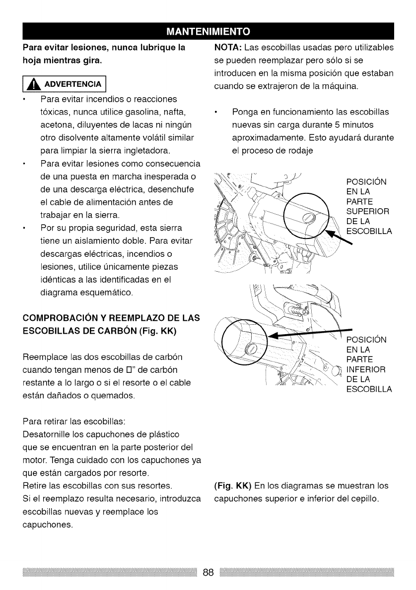
Para evitar lesiones, nunca lubrique la
hoja mientras gira.
[_IL ADVERTENCIA 1
Para evitar incendios o reacciones
t6xicas, nunca utiNce gasoNna, nafta,
acetona, diluyentes de lacas ni ningun
otro disolvente attamente vota.tit similar
para limpiar la sierra ingletadora.
Para evitar lesiones como consecuencia
de una puesta en marcha inesperada o
de una descarga electrica, desenchufe
et cable de atimentacion antes de
trabajar en la sierra.
Por su propia seguridad, esta sierra
tiene un aislamiento dobte. Para evitar
descargas electricas, incendios o
lesiones, utiNce L_nicamentepiezas
identicas alas identificadas en et
diagrama esquema.tico.
COMPROBACION Y REEMPLAZO DE LAS
ESCOBILLAS DE CARBON (Fig. KK)
Reemptace las dos escobillas de carbon
cuando tengan menos de 17"de carbon
restante a Io largo o si et resorte o et cable
est&n dafiados o quemados.
Para retirar las escobiNas:
Desatornille los capuchones de pta.stico
que se encuentran en la parte posterior det
motor. Tenga cuidado con los capuchones ya
que esta.n cargados pot resorte.
Retire las escobitlas con sus resortes.
Si et reemptazo resutta necesario, introduzca
escobiNas nuevas y reemptace los
capuchones.
NOTA: Las escobitlas usadas pero utitizabtes
se pueden reemptazar pero solo si se
introducen en la misma posicion que estaban
cuando se extrajeron de la ma.quina.
Ponga en funcionamiento las escobiltas
nuevas sin carga durante 5 minutos
aproximadamente. Esto ayudara, durante
et proceso de rodaje
POStCION
EN LA
PARTE
SUPERIOR
DE LA
ESCOBILLA
POStCION
EN LA
PARTE
INFERIOR
DE LA
ESCOBILLA
(Fig. KK) En los diagramas se muestran los
capuchones superior e inferior det cepillo.
88
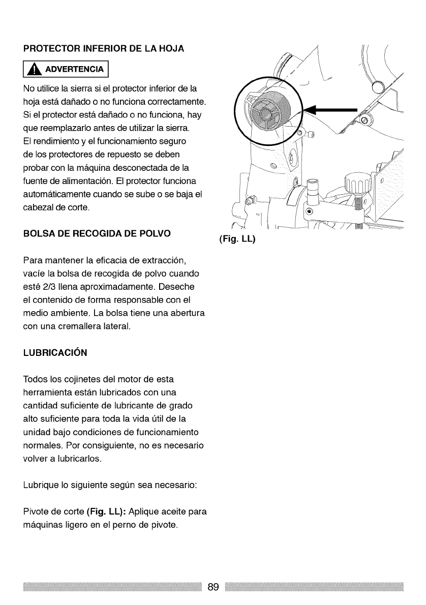
PROTECTOR INFERIOR DE LA HOJA
,_ ADVERTENCIA 1
No utilice la sierra si el protector inferior de la
hoja est& daSado o no funciona correctamente.
Si el protector est& daSado o no funciona, hay
que reemplazarlo antes de utilizar la sierra.
El rendimiento y el funcionamiento seguro
de los protectores de repuesto se deben
probar con la m&quina desconectada de la
fuente de alimentaci6n. El protector funciona
autom&ticamente cuando se sube o se baja el
cabezal de corte.
BOLSA DE RECOGIDA DE POLVO
Para mantener la eficacia de extracci6n,
vacfe la bolsa de recogida de polvo cuando
este 2/3 Ilena aproximadamente. Deseche
el contenido de forma responsable con el
medio ambiente. La bolsa tiene una abertura
con una cremallera lateral.
LUBRICACION
Todos los cojinetes del motor de esta
herramienta est&n lubricados con una
cantidad suficiente de lubricante de grado
alto suficiente para toda la vida etil de la
unidad bajo condiciones de funcionamiento
normales. Por consiguiente, no es necesario
volver a lubricarlos.
Lubrique Io siguiente segen sea necesario:
Pivote de corte (Fig. LL): Aplique aceite para
maquinas ligero en el perno de pivote.
(Fig. LL)
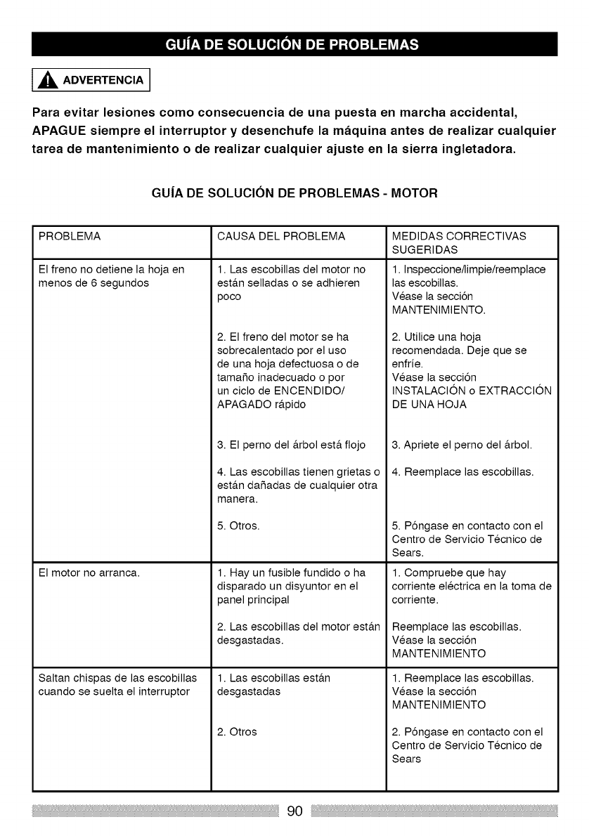
,_ ADVERTENCIA
Para evitar lesiones como consecuencia de una puesta en marcha accidental,
APAGUE siempre el interruptor y desenchufe la maquina antes de realizar cualquier
tarea de mantenimiento o de realizar cualquier ajuste en la sierra ingletadora.
GU|A DE SOLUCION DE PROBLEMAS - MOTOR
PROBLEMA CAUSA DEL PROBLEMA
El freno no detiene la hoja en
menos de 6 segundos
El motor no arranca.
Saltan chispas de las escobillas
cuando se suelta el interruptor
1. Las escobillas del motor no
est&n selladas o se adhieren
poco
2. El freno del motor se ha
sobrecalentado por el uso
de una hoja defectuosa o de
tamaSo inadecuado o por
un ciclo de ENCENDIDO/
APAGADO r_.pido
3. El pemo del _.rbol est.. fiojo
4. Las escobillas tienen grietas o
est&n daSadas de cualquier otra
manera.
5. Otros.
1. Hay un fusible fundido o ha
disparado un disyuntor en el
panel principal
2. Las escobillas del motor est_.n
desgastadas.
1. Las escobillas est_.n
desgastadas
2. Otros
MEDIDAS CORRECTIVAS
SUGERIDAS
1. Inspeccione/limpie/reemplace
las escobillas.
Vease la secci6n
MANTENIMIENTO.
2. Utilice una hoja
recomendada. Deje que se
enfrie.
Vease la secci6n
INSTALACION o EXTRACCION
DE UNA HOJA
3. Apriete el perno del _.rbol.
4. Reemplace las escobillas.
5. P6ngase en contacto con el
Centro de Servicio Tecnico de
Sears.
1. Compruebe que hay
corriente electrica en la toma de
corriente.
Reemplace las escobillas.
Vease la secci6n
MANTENIMIENTO
1. Reemplace las escobillas.
Vease la secci6n
MANTENIMIENTO
2. P6ngase en contacto con el
Centro de Servicio Tecnico de
Sears
90
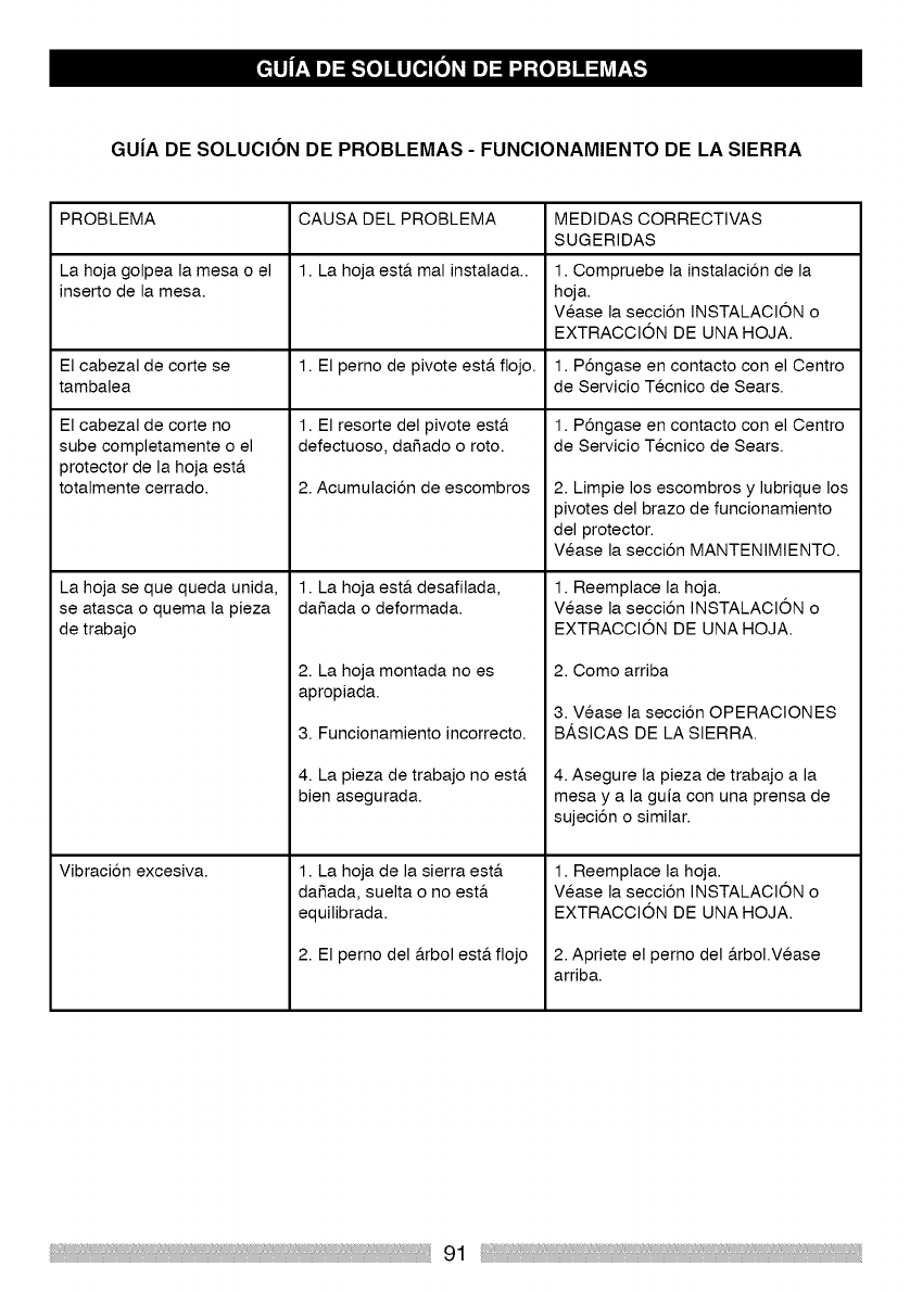
GU|A DE SOLUCION DE PROBLEMAS - FUNCIONAMIENTO DE LA SIERRA
PROBLEMA CAUSA DEL PROBLEMA MEDIDAS CORRECTIVAS
SUGERIDAS
La hoja golpea la mesa o el 1. La hoja est& mal instalada.. 1. Compruebe la instalaci6n de la
inserto de la mesa. hoja.
Vease la secci6n INSTALACION o
EXTRACClON DE UNA HOJA.
El cabezal de corte se 1. El perno de pivote est& flojo. 1. P6ngase en contacto con el Centro
tambalea de Servicio Tecnico de Sears.
1. El resorte del pivote est,. 1. P6ngase en contacto con el Centro
defectuoso, daSado o roto. de Servicio Tecnico de Sears.
2. Acumulaci6n de escombros
1. La hoja est& desafilada,
daSada o deformada.
El cabezal de corte no
sube completamente o el
protector de la hoja est&
totalmente cerrado.
La hoja se que queda unida,
se atasca o quema la pieza
de trabajo
Vibraci6n excesiva.
2. La hoja montada no es
apropiada.
3. Funcionamiento incorrecto.
4. La pieza de trabajo no est&
bien asegurada.
1. La hoja de la sierra est&
da5ada, suelta o no est&
equilibrada.
2. El perno del &rbol est& flojo
2. Limpie los escombros y lubrique los
pivotes del brazo de funcionamiento
del protector.
Vease la secci6n MANTENIMIENTO.
1. Reemplace la hoja.
Vease la secci6n INSTALACION o
EXTRACClON DE UNA HOJA.
2. Como arriba
3. Vease la secci6n OPERACIONES
BASICAS DE LA SIERRA.
4. Asegure la pieza de trabajo a la
mesa y a la guia con una prensa de
sujeci6n o similar.
1. Reemplace la hoja.
Vease la secci6n INSTALACION o
EXTRACClON DE UNA HOJA.
2. Apriete el perno del &rbol.Vease
arriba.
91

Your Home
For troubleshooting, product manuals and expert advice:
www.managemylife.com
For repair - in your home - of all major brand appliances,
lawn and garden equipment, or heating and cooling systems,
no matter who made it, no matter who sold it!
For the replacement parts, accessories and
owner's manuals that you need to do-it-yourself.
For Sears professional installation of home appliances
and items like garage door openers and water heaters.
1-800-4-MY-HOME ®(1-800-469-4663)
Call anytim e, day o r n ight (U.S.A. and Ca nad a)
wwwse.rscom wwwse.rsc.
ourHome
For repair of carry-in items like vacuums, lawn equipment, 1i
and electronics, call anytime for the location of your nearest
Sears Parts & Repair Service Center
1-800-488-1222 (USA) 1-800-469-4663 (Canada) i
[www,sears,com www,sears,ca
To purchase a protection agreement on a product serviced by Sears:
1-800-827-6655 (U.S.A.) 1-800-361-6665 (Canada)
Para pedir servicio de reparaci6n Au Canada pour service en fran£ais:
a domicilio, y para ordenar piezas: 1-800-LE-FOYER Mc
1-888-SU-HOGAR* {1-800-533-6937)
(1-888-784-6427) www.sears.ca
........................................................................................a V'¢"
TM
® Registered Trademark /Trademark of NOD tP, LLC in the United States, or Sears Brands, LLC in ether countries
TM
® Maraa Registrada /Marca de Fabrica de NOD tP, LLC en Estados Unidos, o Sears Brands, LLC in otros paises
MCMarque de commerce /r_lDMarque d6posee de Sears Brands, LLC
