Craftsman 137212140 User Manual MITER SAW Manuals And Guides LR708226
CRAFTSMAN Miter Saw Manual LR708226 CRAFTSMAN Miter Saw Owner's Manual, CRAFTSMAN Miter Saw installation guides
User Manual: Craftsman 137212140 137212140 CRAFTSMAN MITER SAW - Manuals and Guides View the owners manual for your CRAFTSMAN MITER SAW #137212140. Home:Tool Parts:Craftsman Parts:Craftsman MITER SAW Manual
Open the PDF directly: View PDF ![]() .
.
Page Count: 28
Operator's Manual
2.5 HP (Max. Developed)
10" Blade
4800 R.P.M.
COMPOUND MITER SAW
With Laser Trac®
Model 137.212140
CAUTION;
Before using this Miter Saw,
read this manual and follow
all its Safety Rules and
Operating Instructions !Customer Neip Line
t=800=843=t682
eSafety Instructions
eInstallation
•Operation
e Maintenance
e Pads List
Sears, Roebuck and Co., Hoffman Estates,. 1L60179 U.S.A.
Visit our Craftsman website: _w_w, sears.comlcraftsman
Part No.:137212140001

SECTION PAGE
Warranty ................................................ 2
Product Specifications ........................... 2
-Power ToolSafety o............................. 3
Compound Miter Saw Safety ................. 4
Electrical Requirements and Safety ....... 4-5
Accessories and Attachments ............... 6
Tools Needed For Assembly ................... 6
Carton Contents ...................................... 7
SECTION PAGE
Know Your Compound Miter Saw .......... B
Glossary of Terms ................................ 9
Assembly and Adjustments:; _._.,,......... 10
Operation ......... _.................................... 15
Maintenance ............................................ 22
Troubleshooting Guide ............................ 23
Parts List,,,........................................... 24
i i i iiii, _,,i...... i .........ii, -i i,:,,ii - ..... i"': .............. ii
FULL ONE YEAR WARRANTY
if this tool fails due to a defect in material or workmanship within one year ol date of purchase, Sears will
at !ts opt!on repair or replace it free of charge.
Return this tool to a Sears Service Center for repair, or to place of purchase for replacement.
This warranty gives you specific legal dghts, and YOU may also have other rights which may vary from
state to slate,
Sears, Roebuck an dCo., Dept, 817 WA, Hoffman Estates, IL 60179
.................... '..... lUU i ii iiin,llli .................. i, 1,1,,11,
Some dust created by power sanding, sawing, grinding, drilling and other construction activities contains
chemicals known (to the State of California) to cause cancer, birth defects or other reproductive harm. Some
examples of these chemicals are:
=Lead from lead-based paints
•Crystalline silica from bricks, cement and other masonry products
oArsenic and chromiumfrom chemically treated lumber
Your risk from these exposures varies, depending on how often you do this type of work. To reduce your
exposure to these chemicals, work ina well ventilated area and work with approved Safety equipment such as
dust masks that are specially des}gnarl to filter out microscopic particles.
:MOTOR :Rotating Table;
iPower source.......................... 120 V AC; 6OHZIi5 Amp Diamatero_o,,::.,. ........................ t2.S/B"
Horsep0wer.;.L_...........i,... :;. 2,SHP (Max, Devet0ped} Mtter Detent Stops, ..................... 0, 15, 22o1.,'2,31.6,
Arbor Shaft Size 5./B" .... .... 45= R. & L
Speed.; ........_.o..o.;......... .,,,_. 4800 RPM(No load) Bevei P0sitiveStaps_..:,.,,.:o,.,,,;, 0, 45= :
Brake.:.;.;; .............................. Electric Base Dirnensions,.o,i..i.,.;.i=_.... 20-112,x16..1t4"
: Double Insulated................,:;.... Yes Dust Collection........ :L,.;......... Yes
MITER SAW Exlension Wings....................... Yes
:Cutting Capacity: NetWeight................................. 33 Lbs
: :Crosscut...... ;.,-,, ... ............. 2-5/8' X 5-1t2"
:: Miler45 '_R&L ..................... 2_/8' x 3-1/2"
: Bevel 45=L................. :........ t-t/2" x 5_1t2=
450 Miler and 45" Bevel.............. 1-1/2"X3-1/2"
To avoid electrical hazards, fire hazards Or damage to the tool, u_e proper¢.Ircuit protection.
This to01 is wired at the factory for 110.120 Volt operation. It must be connected to a 110-120 Volt t15 Ampere time
delay fuse or circuit breaker. To avoid shock or fire, replace power cord immediately If It is worn, cut or damaged
In any way.
Before using your tool, it is critical that you read and understand these safety rules. Failure to follow these rules
could result In serious injury to you or damage to the tool.
GENERAL SAFETY INSTRUCTIONS
BEFORE USING THIS POWER TOOL
Safety is a combinatio_ of common sense, staying ale_
and knowing how to use your power tool
To avoid mistakes that could cause sedous injury,do not
plug the tool in until you have read and _mderstood the
following
1. READ and become familiar with the entire Operators
Manual. LEARN the tool's application, limitations and
possible hazards.
2. KEEP GUARDS IN PLACE and in working order,
3. REMOVE ADJUSTING KEYS AND WRENCHES.
Form the habit of checking to see that keys and
adjusting wrenches are removed from the tool before
turning ONe
4. KEEP WORK AREA CLEAN. Cluttered areas and
benches invite accidents.
5. DON'T USE IN DANGEROUS ENVIRONMENTS.
Don't use power tools in damp locations, or expose
them to rain or snow. Keep work area well lighted.
6. KEEP CHILDREN AWAY. All visilors and bystanders
should be kept a safe distance from work area
7. MAKE WORKSHOP CHILD PROOF with padlocks,
master switches, or by removing starter keys
8. DON'T FORCE THE TOOL. {t wilt do the job better
and safer at the rate for which it was designed.
9. USE THE R1Gt'rr TOOL. Do not force the tool or an
attachment to do a job for which it was not designed,
10,USE PROPER EXTENSION CORDS. Make sure
your extension cord is in good condition. When using
an extension cord, be sure to use one heavy enough
to carry the current your product will draw, An
undersized cord will result in a drop in line voltage
and in loss of power which will cause the tool to
overheat. The table on page 5 shows the correct size
to use depending on cord length and nameplate
ampere rating_ If in doubt, use the next heavier gauge.
The smaller the gauge number, the heavier the cord.
11,WEAR PROPER APPAREL. Do not wear loose
¢10thihg,gloves, neckties, dngs, bracelets, c r other
jewelry which may get caught in moving parts
Nonslip footwear is recommended Wear Drotective
hair covedng to contain long hair.
12.ALWAYS WEAR EYE PROTECTION. Any power tool
can throw foreign objecl_sinto the eyes and
could cause permanent eye damage.
ALWAYS wear Safety Goggias (not
glasses) that comply with ANSI Safety
standard Z87.t Everyday eyeglasses
have onfyimpact -resistance lenses
They ARE NOT safety glasses. Safety Goggles ere
available at Sears, NOTE: Glasses or goggles not in
complianCE with ANS! Z87ol could seriously injure
you wllen they break.
13.WEAR A FACE MASK OR DUST MASK, Sawing
operation produces dust.
14oSECURE WORK. Use clamps or a vise to hold work
when practical. It's safer than using your hand and it
free_ both hands to operate the tool
15.DISCONNECT TOOLS FROM POWER SOURCE
beIore sewicing, and when changing accessories
sucl_ as blades, bits and cutters,
16.REDUCE THE RISK OF UNINTENTIONAL
STARTING. Make sure switch is in the OFF position
before plugging the tool in,
17,USE RECOMMENDED ACCESSORIES. Consult this
Operators Manual for recommended accessories
The use of improper accessories may cause risk ol
injury to yourself or others
1B_NEVER STAND ON THE TOOL. Serious injury could
occur if ]h_ Iool is tipp@dor il the culling tool is
uninlentfona]ly contacted
19oCHECK FOR DAMAGED PARTS. Before further usa
of the tool, a guard or other part that ]s damaged
should be carefully checked to determine th_t it will
operate properly and perform its intended funclion -
check for alignment of moving parts, binding of
moving parts, breakage of pans. mounting, and any
other conditions that may affect its operalion A guard
orother part that is damaged should be properly
repaired or replaced
20°NEVER LEAVE THE TOOL RUNNING UNATTEt._DED.
TURN THE POWER "OFF". Don't wa]k away from a
running toot until the blade comes to a complete stop
& unplug Ihe unit
21.DON'T OVERREACH. Keep proper ioo_ing and
balance at all times,
22.MAINTAIN TOOLS WITH CARE. Keep tools sharp
and clean for bes[ and safest par[ormanceoFoIIow
instrucUonsfor lubricating and changing accessories.
23,WARNING: Dust g_nerated from certain mater;als
can be hazardous to your heaith, Always opera[e saw
in well-ventilated area ant provide for _roper dust
removal
18.MAKE SURE the blade is not contacting the
SPECIFIC SAFETY INSTRUCTIONS FOR workpiece before the switch is turned ON
THIS COMPOUND MITER SAW 19JMPORTANT: After completing the cut, release the
I. USE ONLY CROSS-CUTTING SAW BLADES. When ....... power switch and wait for the blade to stop before
using carbide tipped blades, make sure they have a
negative hook angle.
IMPORTANT: DO NOT USE THtN KERF BLADES-
they can deflecl and conlacl guard and can cause
possible injuryto the operator.
2. DO NOT operate the miter saw until it is completely
assembled and installed according to these
instructions,
3. IF YOU ARE NOT thoroughly familiar with the
operation o! miter saws, seek guidance from your
returning the saw to the raised position..
2&MAKE SURE the blade has come to a compfete stop
before removing or securing the workpiece, changing
the workpiece angle, or changing the angle of the
blade.
21.NEVER cut metals or masonry products with this tool,
This miter saw is designed for use on wood and
wood-like products,
22.NEVER cut small pieces If the workpiece being cut
supervisor instructor, or other qualified person would cause your hand or fingers to be within 7-t/4"
inches of the saw blade the workpiece is too small
4. ALWAYS held the work firmly against the fence and
table. DO NOT pedorm any operalion free hand (use
clamp wherever possible)
5. KEEP HANDS out of the path ot the saw b]ade, If the
werkpiece you are cutting would cause your hands to
be within 7-1/4" inches of the saw blade, the
workpieca should be ciamped in place before making
the cut.
6. BE SURE the blade is sharp, runs freely, and is free
of vibration
7. ALLOW the motor Io come up to fu_lspeed before
starting a cut.
?_3.PROVIDE adequate support to the sldes of the saw
table far long work pieces.
24,NEVER use the miter saw in an area with fiammabb
liq_Jidsor gases
2&NEVER use solvents to clean plastic parts. Solvents
could possibly dissolve or other,,4se damage the
material.
26.SHUT OFF the power belore servicing or adjusting
the too].
27,DISCONNECT the saw from the power source and
clean the machine when finished using
8. KEEP THE MOTOR AIR SLOTS CLEAN and #eeoI
chips or dust, 28.MAKE SURE the work area is clean before leaving
9. ALWAYS MAKE SURE all handles are tight before
cutting, even if the table is positioned in one of the
positbe stops,,
10,BE SURE both the blade and the collar are clean and
the arbor bolt is tightened securely.
11.USE only blade collars specified for your sew.
the machine.
29.SHOULD any pan of your miter saw be missing,
damaged, or fail in any way, or any electrical
component fail te pedorm properly, shut off the switch
and remove the plug from the power supply oullet.
Replace missing, damaged, or falled parts before
resuming operation.
12. NEVER use blades Iarger or smaller in diameter
than 10-inches.
13. NEVER apply lubricants tc the blade when it is
running,
14. ALWAYS check the blade for cracks or damage
before operation. Replace a cracked or damaged
blade immediately.
15. NEVERuse blades recommendedbr operalional
less than4800 RPM.
16.ALWAYS keep the blade guards in place and use at
all times
POWER SUPPLY AND MOTOR SPECIFICATIONS
The AC motor used _n this saw is a uriiverse[.
nonreversible type. See "MOTOR _ in the "PRODUCT
SPECIFICATIONS" seciion on page 2.
To avoid electrical hazards, fire hazard_ or damage 1o
the tool, use proper ,circuit protection. Your saw is wired
at the factory for 120V operatbn Connect to a 120V, 15
Amp circuit and use a I5 amp, time delay lose or circuit
breaker, To avoid shock or fire, if power cord is worn or
cut, or damaged in any way, have it replaced
immediately.
17.NEVER reach around the saw blade
ELECTRICAL REQUIREMENTS - cont'd
DOUBLE INSULATED []
The power tool is double insulated to provide a double
thickness of insulation beb.veen you and tool,s-electrical
system. All exposed metal parts are isolated from the
internal metal motor components with protecting
insulation,
Replacement parts - When servicing use only identical
replacement parts.
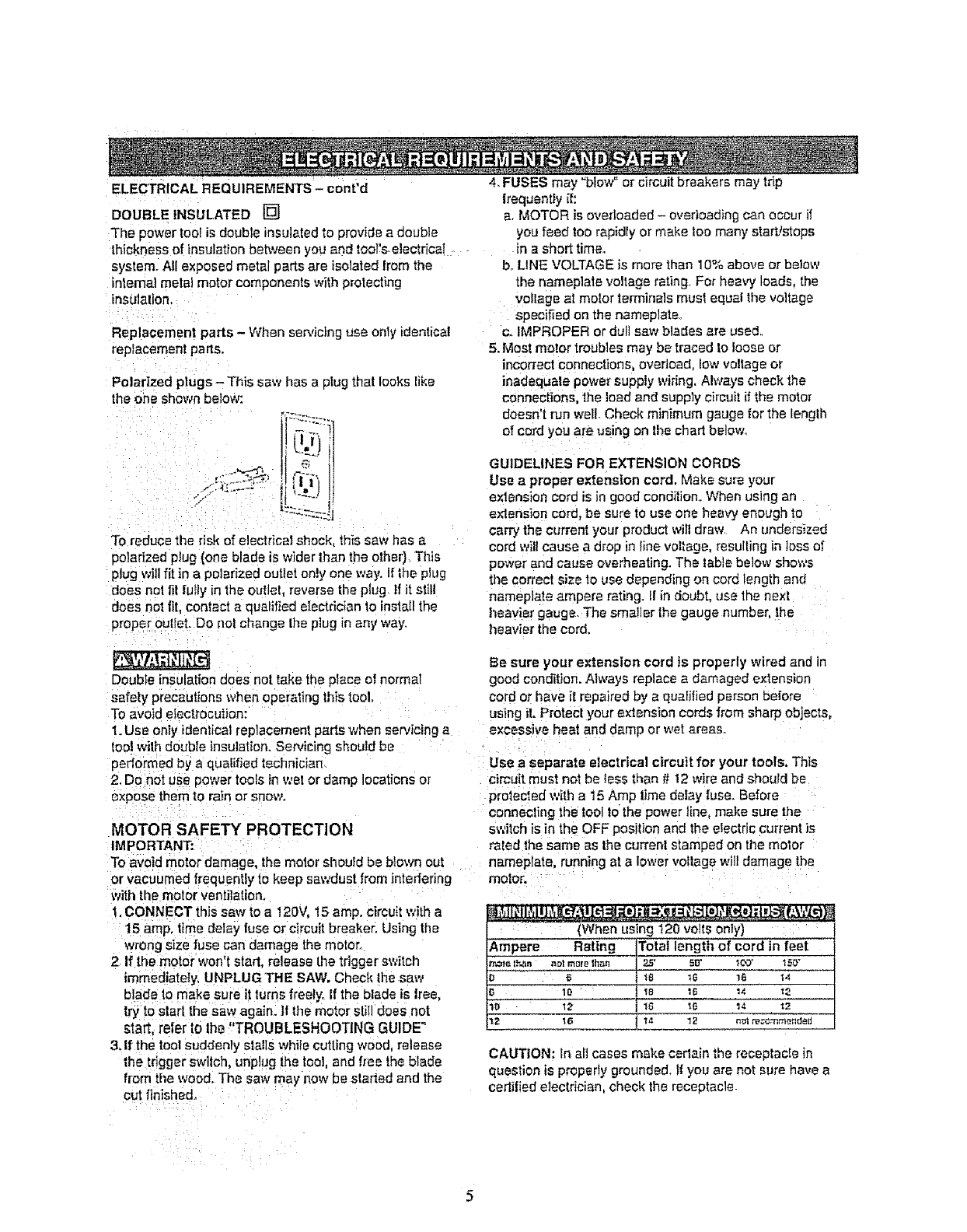
Polarized plugs-This saw has a plug that looks like
the one shown below:
To reduce the risk of eleclricat shock, this saw has a
polarized plug (one blade is wider than the other] Tllis
plug willfit in a polarized outlet only one way. If |he plug
does not fit fully in the curie! reverse the plug tf it st;tl
does not fit, contact a qualified electrician to install the
proper outlet. DO riot change the plug in any way.
Double insulation does not take the place o! normal
safety precautions when operating this tool
To avoid electrocution:
1. Use only identical replacement parts when servicing a
toolwith double Insulation. Servicing should be
performed by a qualified technician
2, Do not use power tools tn wet or damp locations or
expose them to ra'=nor snow.
MOTOR SAFETY PROTECTION
IMPORTANT:
To avoid motor damage, the motor sl_outd be blown out
or vacuumed frequently to keep sawdust from intedefing
with the motor ventilation,
t. CONNECT this saw to a 120V, 15 amp. circuitwith a
15 amp, time delay fuse or circuit breaker. Using the
wrong size fuse can damage the motor..
2 If the motor won't start, release the tdgger swilch
immediately, UNPLUG "THE SAW, Check the saw
blade t.omake sure it turns freely< If the blade is Iree,
try to sled the saw again. If the motor still does not
start, refer to lhe "TROUBLESHOOTING GUIDE"
3. If the tool suddenly stalls while cutting wood, release
the tdgger swltch, unplug the tool, and free the blade
from tile wood. The saw may now be started and the
cut flnisha&
4. FUSES may "blow" or circuit breakers may trip
frequently if:
a. MOTOR is overloaded - ovedoading can occur if
you feed too rapidly or make too many startJstops
in a shod time.
b. LINE VOLTAGE is more than 10% above or below
the nameplate voltage rating For heavy loads, the
voltage at motor terminals must equal the voltage
specified on the nameplate.
c,, IMPROPER or dull saw blades are used,
5. Most motor troubles may be traced to loose or
incorrect connections, overload, low voltage or
inadequate power supply widng, Always check the
connections, the load and supply circuit ifthe motor
doesn't run well. Check minimum gauge for the lenglh
of cord you are using on the chad below,
GUIDELINES FOR EXTENSION CORDS
Use aproper extension cord. Make sure your
exlension cord is in good condition. When using an
ex'lension cord, be sure to use one heavy enough to
carry the current your product will draw, An undersized
cord will cause a drop in line voltage, resulling in loss of
power and cause overheating. The table below shows
the correct size to use depending on cord length and
nameplate ampere rating. II in doubt, use the nexl
heavier gauge The smaller lhe gauge number, the
heavier the cord.
Be sure your extension cord is property wired and in
good condition. Always replace a damaged extension
cord or have it repaired by a qualified person before
using iL Protect your extension cords from sharp objects,
excessive heat and damp or wet areas.
Use a separate electrical circuit for your tools. This
circuit must not be less than # 12 wire and should be
protected with a 15 Amp lime delay fuse. Before
connecting the to01to the power line, make sure the
switch is in the OFF position and the electric current is
raled the same as the current stamped on ti_e motor
nameplate, running at a lower voltage will damage the
motor.
......... (When using 120 volts only)
Amper_e Rating Totat lengt_ of cord in feet
i"r,,_ie l_n n_l more lhan 25' 5[t' Ic_3* t50 +
o _ 18 _6 16 _4
l0 18 15 14 ;_
10 12 16 IS '14 12
1i'_"_ 1S 14 12 n_l re_--'_mm-.nded --
CAUTION: In all cases make cedain the receptacle in
question is properly grounded. I{ you are not sure have a
certified electrician, check the receptacle
RECOMMENDED ACCESSORIES
oUse only sccessories recommended for thismiter
saw. Followinstructions that accompany aocessodes_
Use ot improper accessories may cause hazards
• The use el any cutting toot e×cept 10 inch saw
blades thai meet the requirements under
recommended accessories is prohibited. Do not use
accessories such as shaper cutters or dude sets.
Ferrous metal cutting, the use of abrasive wheels
and the cutting of masonry producL_are prohibited
eDo not attempt to modify this tool or create
accessories not recommended for use with this tool.
Any such alteration or modification is m}suse and
could result in a hazardous condition leading tO
possibleseriousinjury,
ACCESSORIES
Visit your Sears HardwareDepartmentOrsee [he Sears
Power and Hand TootCatalogto purchase
recommendedaccessories for this powertool.
To avoid the risk el personal injury,do not modify this
power tool or use accessories not recommended by
Sears.
Read warnings and conditions on your CARBIDE
TIPPED SAW BLADE. Do not operate the saw without
tile proper saw blade guard in place. Carbide is a very
hard but brittle material Care should be taken while
mounting, using, and storing carbide tipped btades to
prevent accidental damage. Slight shocks, such as
striking the tip while handling, can seriously damage the
bladeo Foreign objects in the workpiece, such as wire or
nails, can also cause tipsto crack or break off. Bo!ero
using, always visually examine the blade and tips tor
bent teeth, cracks, breakage, missing or loose t_ps,or
other damage. Do not use ifdamage is suspected,
Failure to heed safety instructions and warnings can
resull in serious bodily injury.
Phillips screwdriver
6
UNPACKING YOUR MITER SAW
'Toavoid injury from unexpected sta_ing or electrical shock,
do not plug the power cord into a source of power dur}ng
unpacking and assembly, This cord must remain
unplugged whenever you are adjusting!assembling the
saw,
1. Remove the miter saw from the Carton. IMPORTANT:
Do not lilt the miter saw by the switch handle or miter
table handle.. It may cause misatignmenL Lift only by
the buill-In carry handle located at the topof the
machine.
2., Place the saw on a secure siafionary work surface.
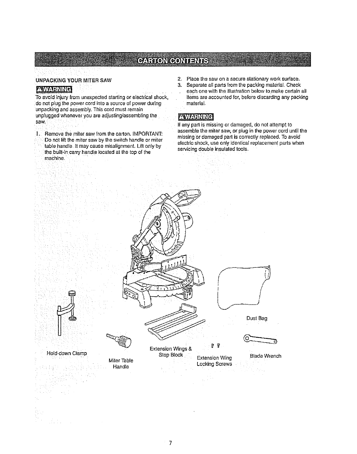
3. Separate all parts from the packing material. Check
.each one with the illustration below lo make certain aJl
items are accounted for, before discarding any packing
material,
If any parl is missing or damaged, do not atlempt to
assemble the miler saw, or plug in the power cord until the
missing or damaged par_is correctly replaced, To avoid
electric shock, use only identical replacement pads when
servicing double insulated lools.
Hold-down Cla_
MilerTable
Handle
Extension Wings &
Stop Block
/
/
/
]
Dust Bag
BladeWrench
ExlensionWing
LockingScrews
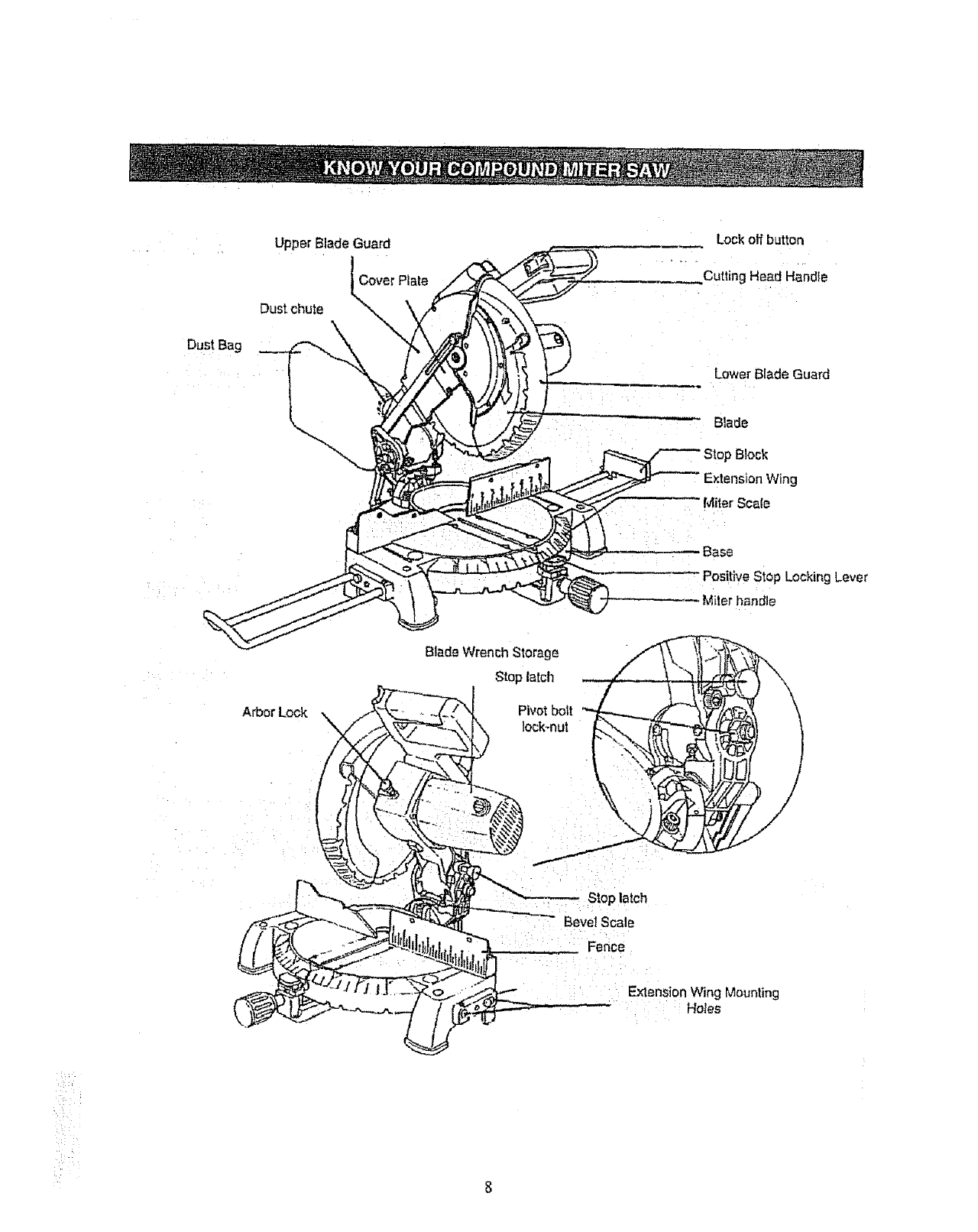
Dust Bag
Upper Blade Guard
Dust chute
Lock off button
Cutting Head Handte
Lower Blade Guard
Blade
g
Miter Scale
Base
" Positive Stop Locking Lever
i;ler handle
Arbor Lock ,_
Stop lalch
Pivot boll
Bevel Scale
: : : Fence
i Ex-lension Wing Mounting
Hotes
CRAFTSMAN COMPOUND MITER SAW TERMS
ARBOR LOCK - Allows the user to keep the btade lmm
rotating while tightening or loosening the arbor locking
bolt during blade replacement or removal.
BASE - Supports the fable, holds accessories and
allows for workbench or leg set mounting
BEVEL LOCKING HANDLE - Locks the miter saw at a
desired bevel angle,
BEVEL SCALE -To measure the bevel angle of the saw
blade O" to 45° left
COVER PLATE SCREW - Loosen this screw and rotate
the plata for access to the blade arbor locking boil
DUST CHUTE - Exhausts debds away Item the user,
EXTENSION WING - Exlends the width of the work
table for support while cutting long work pieces, They
can be used with or without a stop block as an additional
side fence,
FENCE - Helps to keep the workpieca trom moving
when sav4ng Scaled to assist with accurate cutting
HAND HOLD -Location of hands for transportation.
SAFETY LOCK-OFF BUTTON -YeIlow button on
handle must be pushed lorward to activate the trigger
switch,
LOWER BLADE GUARD - Helps protect your hands
from the blade in the raised position, it refracts as file
blade is lowered,
MITER HANDLE -Used to rotate Ihe sew to the fight or
[eft cutting position,
MITER SCALE - To measure the 'niter angle 0_ to 45 °
left, 0 = to 45° fight.
MITER SPRING LOCK - Used in combination with the
miter handle, it locks the miler saw at a preset positive
stop for the desired miter angle,
MOUNTING HOLES - To mount the miter saw to a
stable surface,
ON/OFF TRIGGER SWITCH -To prevent tile trigger
|rom being accidentally engaged, a lock-off slide switch
is provided. To start the fool, push the lock-off slide
switch Ion,yard and squeeze the thgger Release the
trigger to stop the miter saw.
STOP LATCH - Locks the miler saw in the lowered
position for compact sloraga and ttarLsportation.
SWITCH HANDLE - The cutting head handle contains
the tr_gger switchand a safety lock-off Slide switch. The
_lade is lowered into the workpiece by pushing down on
the handle, 'The saw will return to its upright position
when the handle is released,
WARNING LABELS .- Read and understand for your
own safely. Aiways make certain the_e are in place &
legible.
WRENCH STORAGE - Convenient storage to prevent
misplacing the blade wrench
WOODWORKING TERMS
ARBOR - The shaft on which a blade is mounted
BEVEL CUT - An angle cut made through the face of
Lhe workp|ece,
COMPOUND CUT-A simultaneous bevel and miter cuL
CROSS CUT - A cut made across the width or grain of
the workpiece,
FREEHAND - Performing a cut without using a fence
(guide), hold down or other proper device to prevent the
workpiece from twisting during the cutting operation.
GUM - A sticky sap from wood products,
HEEL - MisaIignmenf of the blade.
KERF-The amount of mater;el removed by blade CUL
MITER CUT - An angle cut made across the width or
grain of the workpiece,
RESIN - A sticky sap that has hardened.
REVOLUTIONS PER MINUTE (RPM} - The r'=umber ot
turns completed by a spinning objecl in one minute,
SAW BLADE PATH - The area of the workplace or table
top directly in line with the travel of the blade or the parl
of the workpiece which wil! be cm,
SE'r - The distance between two saw blade tips, bent
oub,,,,ardin opposite directions to each other. The further
apart the tips are, the greater the set.
WORKPIECE - The item being cut. The surfaces o! a
workpiece are commonly referred to as faces, ends, and
edges°
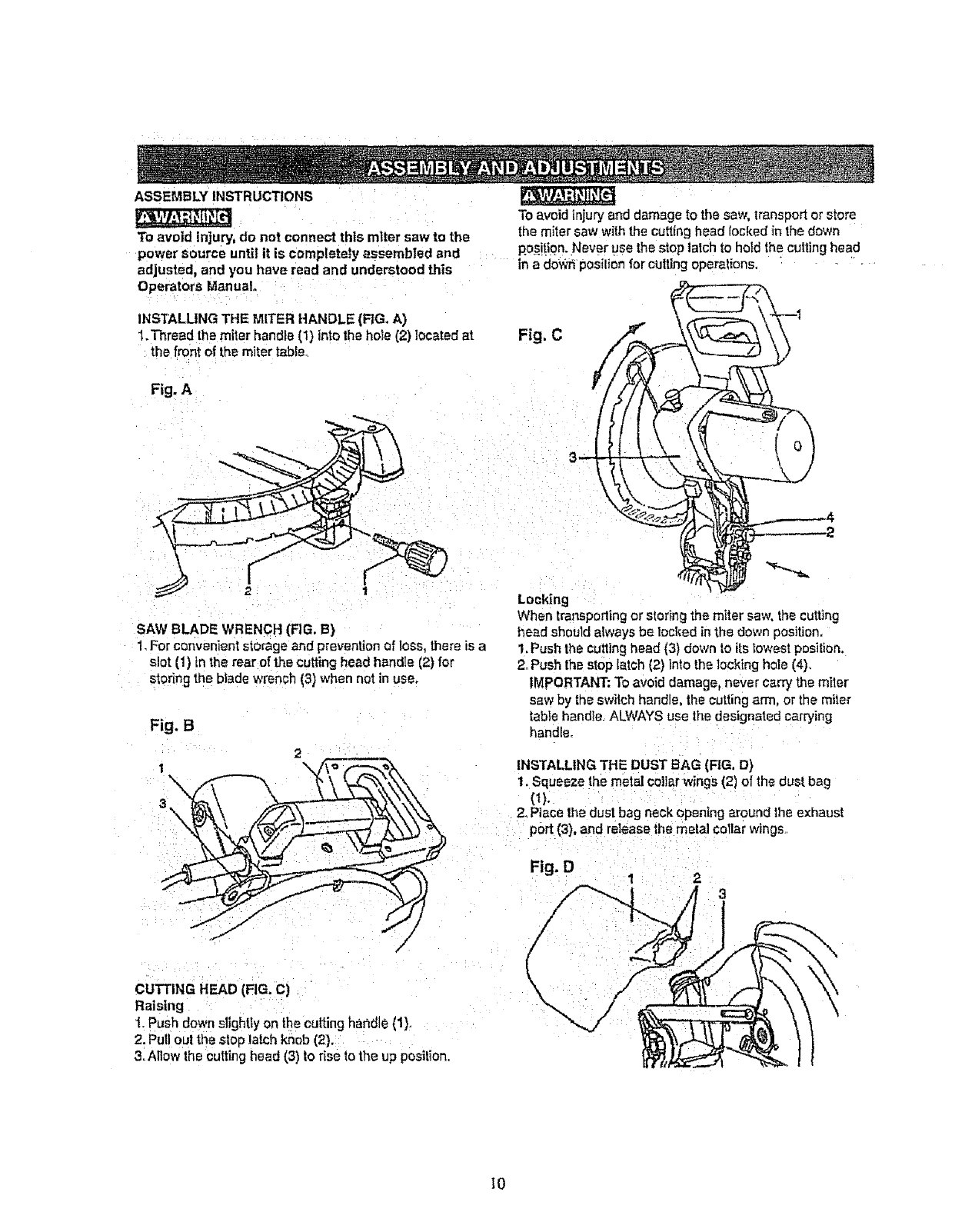
ASSEMBLY INSTRUCTIONS
To avoid injury, do not connect this miter saw to the
power source until it is completely assembled and
adjusted, and you have read and understood this in a do_ pos:liO_for cutting operations,
Operators Manual.
INSTALLING THE MITER HANDLE (FIG, A)
1.Thread the miter handie (1) into the hole (2) located at
the front of th_ miter table
Fig. A
To avoid injury and damage to the saw, transport or store
the miter saw with the cutting head bcked in the down
position. Never use the stop latch to hold the cuing head
Fig. C
3
SAW BLADE WRENCH [FIG. B)
1_For convenient storage and prevention of loss, there is a
slot (1) in the rear of the cutting head handle (2) for
storing the blade wrench I3) when not in use.
Fig. B
2
\"=
/
CUTTING HEAD (FIG. C)
Raising
t. Push down sllghtty on the cutting hat, die (1).
2. Pull out the stop latch knob (2).
3. Allow the cutting head {3) to rise to the up position.
Locking
When transportingor storing the miter saw. the cut'dng
he_d should atways be locked in the down position.
1. Push the cutting head (3) down to its lowest position.
2oPush ths stop latch (2) into the locking hole (4).
IMPORTANT; To avoid damage, never carry the miler
saw by the switch handle, the cutting arm, or the miter
table handle. ALWAYS use the designated carrying
handle.
INSTALLING THE DUST BAG (RG, D)
1. Squeeze the metal collar wings (2) of the dust bag
(t).
2. Place the dust bag neck opening around the exhaust
pert (3), and release the metal collar wings
Fig. D
/
(
\
23
I0
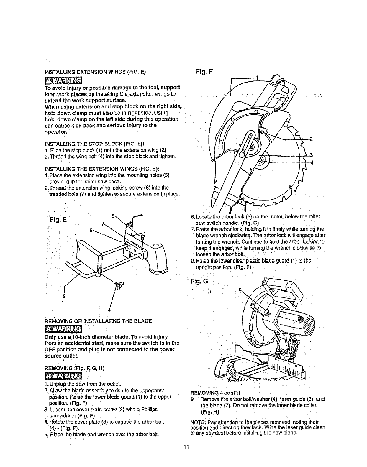
INSTALLING EXTENSION WINGS (FIG, E)
To avoid injury or possible damage to the tool, support
long:work pieces by installing the extension wings to
extend the work support surface.
When using extension and stop block on the right side,
hold down clamp must also be In right side, Using
hold down clamp on the left side during this operation
can cause klck-back and serious injury to the
operator.
Fig. F
INSTALLING THE STOP BLOCK (FIG, E):
1. Stide the stop block (1) onto [he extension wing (2)
2, Thread the wing bolt (4) into the stop block and tighten.
INSTALLING THE EXTENSION WINGS (FIG. E):
1.Place the extension wing into the mounting holes (5)
provided in the miter saw base_
2.Thread the extension wing locking screw (6) into the
treaded hole (7) and tighten to secure extension in place.
(5) on the motor, below the miter
sew switch handle. (Fig, G)
7, Press the arbor lock, holding it in firmly while turning the
blade wrench clockwise. The arbor lock wtll engage after
turning the wrench. Continue to hotd the arbor locking to
keep it engaged, while turning the wrench clockwise to
loosen the arbor bolt,
B.Raise tho lower clear plastic blade guard (1) to the
upright position, (FIg, F)
Fig, G
REMOVING OR INSTALLATING THE BLADE
Only use a lO-inch diameter blade. To avoid Injury
from an accidental start, make sure the switch is in the
OFF position and plug is not connected to the power
source outlet.
REMOVING {Fig, F, G, H)
1. Unplug the saw from the outfet,
2. Allow th_ blade a_embly to _e to the ut_._er_ost
posilion..Raise the lower blade guard (1) to the upper
position° (Fig, F)
3. Loosen the cover plate screw (2) with a Phillips
screwdriver (Fig, F)o
4. Rotate the cover plate (3) to expose the arbor bolt
(4) - (Fig. F).
5. Place the blade end wrench over the arbor bolt
REMOVING - cont'd
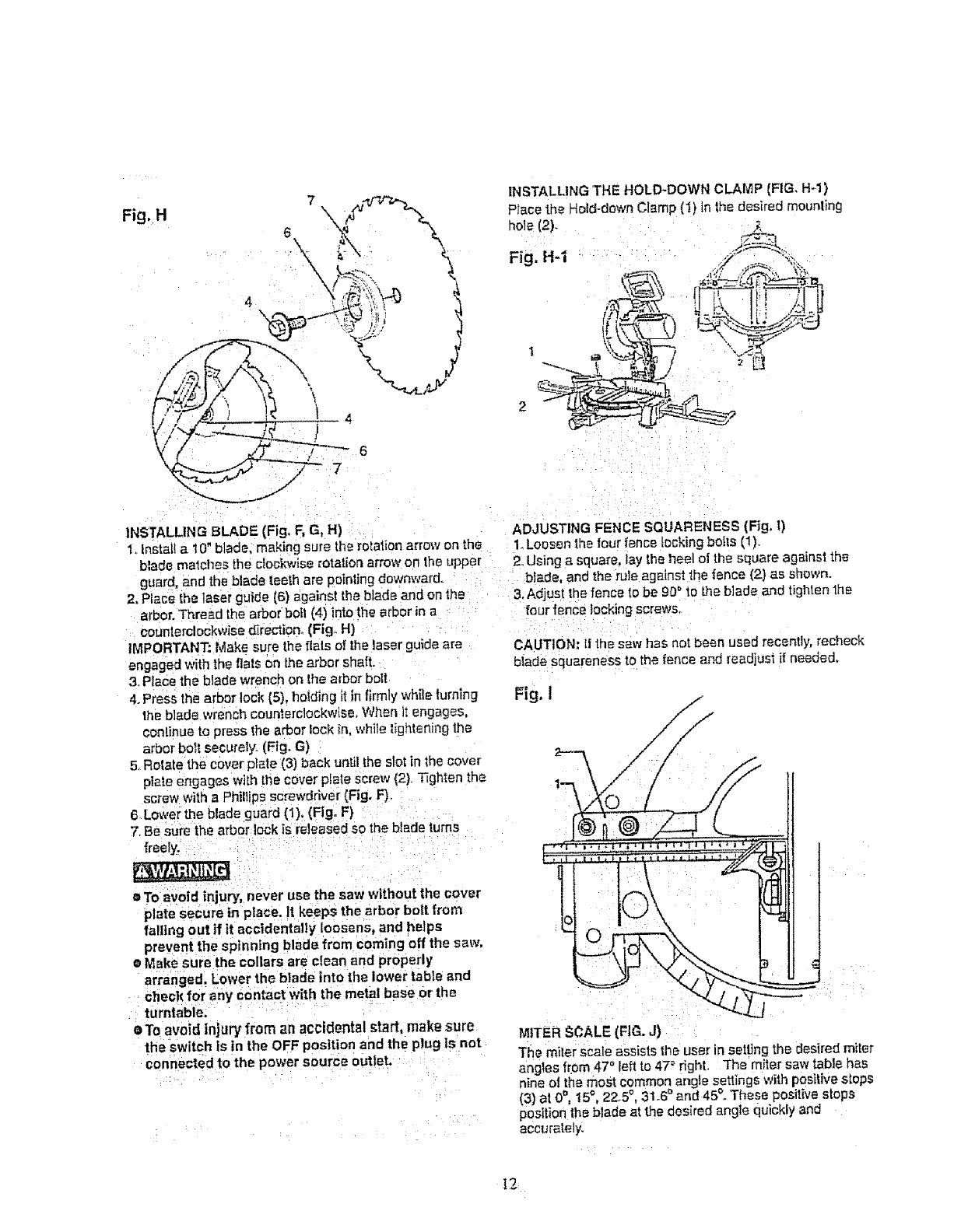
9. Remove the arbor bolt!washer (4), taser guide (6), and
the blade (7)o Do not remove the inner blade collar.
(FIg, H)
NOTE; Pay attention to thepieces removed, noting lhe]r
position and direction they Iase. Wipe the laser guide clean
of any SaWdUStbefore inslal]ingthe new blade.
]1
Fig,H
INSTALUNG BLADE (Fig, F, G, H) ADJUSTING FENCE SQUARENESS (Fig. I)
1oInstal! a 10" blade, making sure the rotation arrow on the 1. Loosen lhetour fence tocking boils (1).
blade matches the clockwise rotation arrow on the upper 2. Using a square, lay the heel ot the square against the
guard, and the blade teeth are pointing downward, blade, and the rule agoinst the fence (2) as shown.
2. Place the laser guide {6) against the blade and on the 3. Adjust the fence to be 9D_ to the blade and tighten lhe
arbor. 'Thread the arbor boll (4) into the arbor in a four fence locking screws.
counlerclockw_sedirection (Fig° H)
IMPORTANT: Make sure the rials of the laser guide are
engaged with the rials on the arbor shaft.
3, Place the blade wrench on the arbor bolt
4. Press the arbor lock [5), holding it in f_rmly wh:le turning
the blade wrench counferclockwise. When it engages,
continue to press the arbor fock in, while tightening the
arbor bol! securely, (Fig. G)
5. Rotate the cover plate (3) back until the slot in the cover
plate engages with tl_e cover pIate screw (2). Tighten the
screw with a Phillips screwdriver (Fig, F)
6 Lower the blade guard (1). (Fig. F)
7. Be sure the arbor lock is released so the blade turns
"freely.
roTe avoid injury, never use the saW without the cover
plate secure in piece. It keeps the arbor bolt from
failing out if it accidentally loosens, and helps
prevent the spinning blade from coming off the saw.
•Make sure the collars are clean and properly
arranged. Lower the btade into the lower table and
check for any contact with the metal base or the
turntable.
• To avoid injury from an accidental start, make sure
ttie switch is in the OFF position and the plug isnot
connected to the power source outlet.
CAUTION: 11the sew has not been used recently, recheck
blade squareness to the fence and readjust if needed,
Fig, I
MITER gCALE (FIG. J)
The miler scale assists tile user in setting the desired miter
angtes from 470 Ieft to 47= right. The miter saw table has
nine el the most common angle settings with positive steps
(3) at 0_, 15_, 22-5'_,31.6 _ and 45_. These positive slops
position the blade at the desired angle quickly and
accurately.
I2¸¸¸
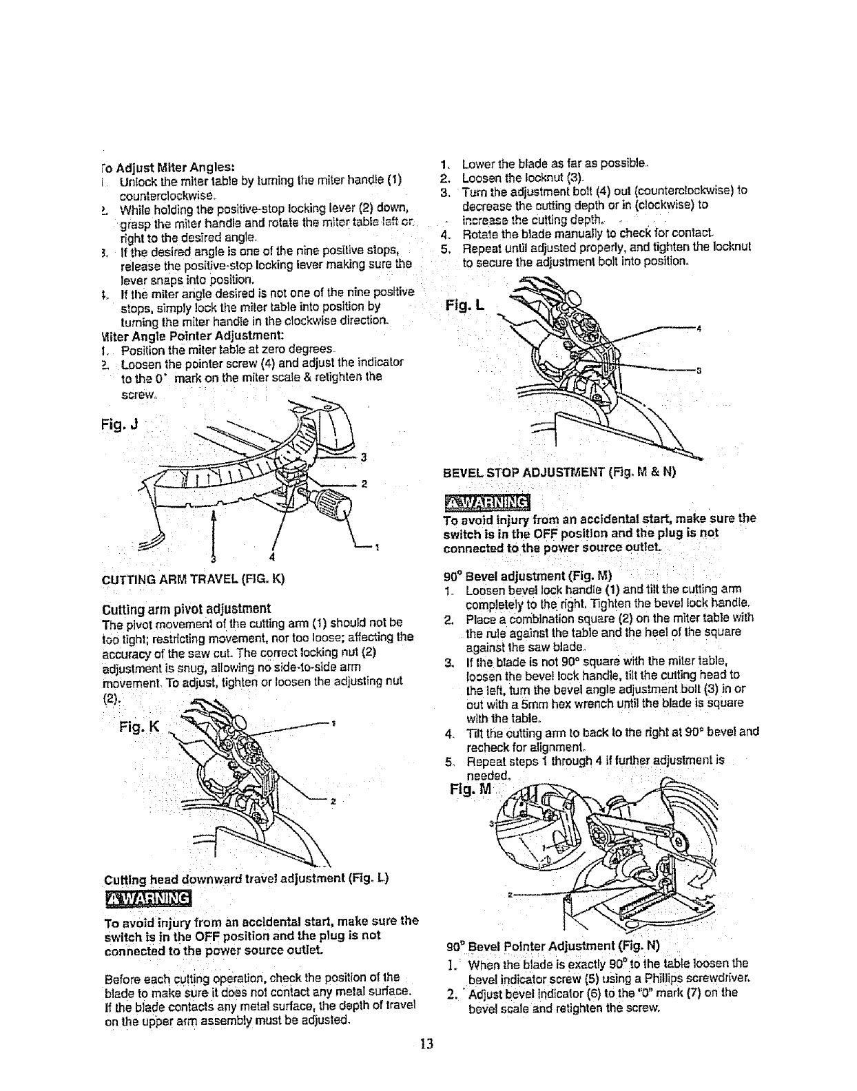
Fo Adjust Miter Angles:
L Unlock the miter table by turning the miter handie (1)
counterclockwise,
LWhile holding the positive-stop locking lever (2) down,
grasp the miter handle and rotate the miter table l_'t or
right to the desired angle_
3. If th_ desired angle is one of the nine positive stops,
release the positive.,stop locking lever making sure tile
lever snaps into posiUun.
t If the miter angle desired i$ no! one of the nine posffive
stops, simply lock the miter table into position by
turning lhe miter handte in the clockwise direction.
Vliter Angle Pointer Adjustment:
t, Position the miter table at zero degrees
Loosen the pointer screw (4) and adjust the indicator
to the 0" mark on the miter scale & retighten the
Fig. J
4
CUTTING ARM TRAVEL (FIG. K)
Cutting arm pivot adjustmsnt
The pivot movement of the cutting arm (t) should not be
too tight; restricting movement, nor too loose; affecting the
accuracy of the saw cut. The correct lucking nut (2)
adjustment is snug, allowing no side-to-side arm
movement To adjust, tighten or loosen the adjusting nut
(2).
1, Lower the blade as tar as possible,
2. Loosen the lookout (3).
3. Turn the adjustment bolt (4) out (counterclockwise) to
decrease the cutting depth or in (clockwise) to
increase the cutting depth,
4. Rotate the blade manually to check for coniacL
5. Repeat until adjusted properly, and tighten the lockout
to secure the adjustment boil into position.
Fig. L
BEVEL STOP ADJUSTMENT" (F_g_M & N)
TO avoid Injury from an accidental start, make sure the
switch is in the OFF position and the plug is not
connected to the power source outlet.
90" Bevel adjustment (Fig. M)
1. Loosen bevel lock handle (1) and tilt the cutting arm
completely to the right, Tighten the bevel lock handle,
2, Place a combination square (2} on the miter table with
the rule against the table and the heal of the square
against the saw blade,
3. If the blade is not 90 °square with the miter table,
loosen the bevel lock handle, tilt the cutting head to
the left, turn the bevel angle adjustment bolt (3) in or
out with a 5me hex wrench until the blade is square
with the table.
4. Tilt the cutting arm to back to the right at 90° bevel and
recheck for alignment,
5_ Repeat steps 1 through4 if lurther adjustment is
needed.
Fig. M
Cutting head downward travel adjustment (Fig. L)
To avoid injury from an accidental start, make sure the
switch is in the OFF position and the plug is not
connected to the power source outleL
Before each culling operation, check the position o{ the
blade to make sure it does not contact any metal surface.
If the blade contacts any metal surface, the depth of travel
on the upper arm assembly must be adjusted.
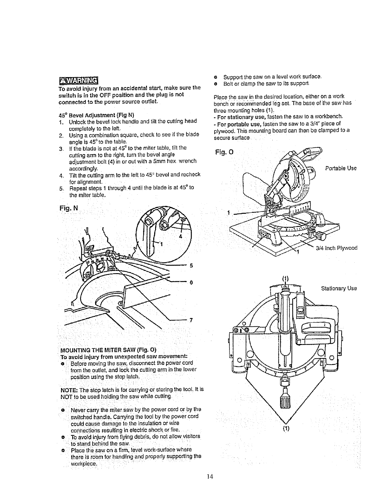
90' Bevel Pointer AdjustmEnt (Fig. N)
]. When the blade is exactly 90° to the table loosen the
bevel indicator screw (5) using a Phillips screwdriver,
2. "Adjust bevel indicator [6) to the "0" merit (7) on the
bevel scale and retighten the screw.
t3
To avoid injury from an accidental start, make sure the
switch is in the OFF position and the plug is not
connected to the power source outlet°
45° Bevel Adjustment (Fig N)
1. Unlock the bevel lock handle and tilt the cutting head
completely to the left
2. Using a combination square, check 1osee ff Ihe blade
angle is 45°t0 the table,
3. If the blade is not at 45_to the miter table, lilt the
cutting arm to the dght, turn the bevel angle
adjustment bolt (4) in or out with a 5ram hex wrench
accordingly,
4. Tilt the cutting arm to the left to 45 = bevel and recheck
for alignment..
5. Repeal steps 1 _rough 4 untilthe blade is at 45°to
the miler table,
Fig. N
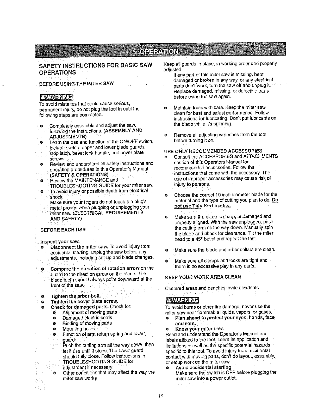
eSupport the saw on a }evel work surface.
eBolt or clamp the saw to its support
Place the saw in the desired location, either on a work
benchor recommended teg set. 3he base of the saw has
three mounting holes (1).
- For stationary use, fasten the saw to a workbench.
- For portable use, fasten the saw Io a 3!4" piece of
plywood. This mounting board can then be clamped to a
secure sudace
Fig.O
Portable Use
_4 inch Plywood
MOUNTING THE MITER SAW (Fig. O)
To avoid injury from unexpected saw movement:
eBefore moving the saw, disconnect the power cord
from the outlet, and lock the cutting arm in the lower
position using the stop latch,
NOTE: The stop latch is for carrying or storing the tool It is
NOT to be used holding the sew while cutting
eNever carry the miter saw by the power cord or by the
switched handle. Carrying the tool by the power cord
could cause damage to the insulation or wire
connections resulting in electric shock or fire.
eTo avoid injury from flying debris, do not allow visitors
to stand behind the saw.
ePlace the saw on a firm, level work-surface where
there is room for handling and properly supporting the
workplace.
(1)
nary Use
]4
SAFETY INSTRUCTIONS FOR BASIC SAW
OPERATIONS
BEEORE UStNGTHE [_FFER SAW ....
To avoid mistakes that coufd cause serious,
permanent injury, do not plug the tool in until the
following steps are completed:
• Completely assemble and adjust the saw,
following the instructions. (ASSEMBLY AND
ADJUSTMENTS)
eLearn the use and function o[ the ON/OFF s_tch,
lock-off switch, upper and lower blade guards,
SlOP latch, bevel lock handle, and cover plate
screws,
eReview and understand all safety instructions and
operating procedures in this Operator's Manual
(SAFETY & OPERATIONS)
oReview the MAINTENANCE and
TROUBLESHOOTING GUIDE for your m_ter saw.
e To avoid injury or possible death from electrical
shock:
Make sure your fingers do not touch the plug's
metal prongs when plugging or unplugging your
miter saw. (ELECTRICAL REQUIREMENTS
AN D SAFETY)
BEFORE EACH USE
Inspect your saw.
e Disconnect the miter saw, To avoid injuryfrom
accidental starting, unplug the saw before any
adjustments, including set-up and biade changes.
Compare the direction of rotation arrow on the
guard to the direction arrow on the blade. The
blade _eeth should always point downward al the
front of the saw.
oTighten the arbor bolt,
Tighten the cover plate screw.
Check for damaged parts, Check for:
o Alignment of moving pans
oDamaged electric cords
oBinding of moving parts
a Mounting holes
• Function of arm return spring and lower
guard:
Push the cutting arm all the way down, tI_en
lel it dse until it stops. The lower guard
should fully close. Follow instructions in
TROUBLESHOOTING GUIDE for
adjustment i! necessary
Other conditions that may affect lhe way the
miter saw works
Keep all guards in place, in working order and properly
adjusted
If any part of this miter saw is missing, bent
damaged or broken in any way, or any =_lectrica]
parts d6fft work, turn the saw off an_ unplug tL_
Replace damaged, missing, or defective parts
before using the saw again,
Maintain tools with care. Keep the miter saw
clean for best and safest performance. Follow
instructions for lubricating. Don't put lubricants on
the blade willie it's spinning.
o Remove all adjusting wrenches from the tool
before turning it on
USE ONLY RECOMMENDED ACCESSORIES
oConsult 1he ACCESSORIES and ATTACHMENTS
section of this Operators Manual ;or
recommended accessories Follow the
instructions that come with the accesso,_. The
use of improper accessories may cause risk el
injury to persons,
o Choose the correct 10 inch diameter blade for the
material and the type of cu_ing you plan to do. Do
not use Thin Kerfblades.
Make sure the blade is sharp, undamaged and
properly aligned. Wilh the saw unplugged, push
the cutting arm elf the way down. Manually spin
the blade and check for clearance, T_ltthe miter
head to a45 _ bevel and repeat the test.
o Make sure the biade and arbor coliars are clean.
eMake sure all clamps and locks are light and
there is no excessive play in any parts.
KEEP YOUR WORK AREA CLEAN
Clultered areas and benches invite accidents.
To avoid burns or other fire damage, never use the
miter saw near ffammab]e liquids, vapors, or gases,
mPlan ahead to protect your eyes, hands, face
and ears,
eKnow your miter saw.
Read and understand the Operator's Manual and
tabels_affixed to the tOOLLearn its application and
]]inflations as well as the specific potential hazards
specific to this tool. To avoid injury from accidental
contact with moving parts, don't do layout, assembly,
or setup work on the miter saw.
oAvoid accidental starting
Make sure the switch is OFF before plugging the
miter saw into a power outlet.
15
PLAN YOUR WORK
oUse the tight tool, Don't force a too] or attachment
to do a job it was not designed to do, Use a
different tool for any workpiece that can't be held
- • in a-solidly braced, fixed position ...... -.... o
CAUTION; This machine is NOT designed for cutting
masonry, masonry products & ferrous metals (steel,
iron, and iron-based metals ,) Use this miter saw to cut
only wood and wood by-products. Other material may
shatter, bind the blade, or create other dangers,
Remove eli nails that may be in the workpiece to •
prevent sparking that could cause a fire.
O
DRESS FOR SAFETY
Any power tool can throw foreign objects into tt3e eyes.
This can result in permanenl eye damage. Everyday
eyeglasses have only impact resistant lenses and are =_
not safety glasses. Glasses or goggles not in
compliance with ANSI Z87 1 could seriously injure you
when they break.
eDo not wear loose clothing, gloves, neckties or
jewelry (rings, watches). They can get Caught and
draw you into moving parts, e
• Wear non-slip footwear,
e Tie back long hair,
= Roll long sleeves above the elbow.
e Noise levels vary widely, To avoid possible
heating damage, wear ear plugs when using any o
miter saw.
e For dusty operations, wgar a dust ma_k along
with safety goggles.
workpieee, fence and table that will let the
workpiece shift after ff is cut.
Keep the cut off piece free to move sideways after
it is cut ell Otherwise, it could get wedged
against the blade and thrown vioIenw,
Only lhe workplace should be on the saw's table,
Secure work. Use clamps or a vise to help hold
the work when it's practical.
USE EXTRA CAUTION WITH LARGE OR ODD
SHAPED WORKPIECES.
Use extra supports (tables, sawhorses, blocks,
etc,) for workpieces large enough to tip°
Never use another person as a substitute for a
table extension, or as an addilJonal support for a
workplace that is longer or wider than the basic
miter saw table, or to heJp feed, support, or pull
the workplace.
Do not use this saw to cut small pieces, It the
workplace being cut would cause your hand or
fingers to be within 7-tt4" inches of the saw blade
workpiece is too small Keep hands and fingers
out of the =no hands zone" area marked on the
saws table.
When cutting odd shaped wolf{pieces, plan your
work so it will not bind in the blade and cause
._ossible injury. Molding, for example, must lie flat
or be held by a fixture or jig that will not let it move
when cut.
Properly support round material such as dowel
rods. or tubing, which have a tendency to roll
when cut, causing the blade to "bite".
INSPECT YOUR WORKPIECE
Make sure there are no nails or foreign objects in the
part of the workpiece being cut.
Plan your work to avoid small pieces that may bind,
or that are too small to clamp and get a solid grasp
on.
Plan the way you wilt grasp the workpiece from start to
finish. Avotd awkward operations and hand positions,
Asudden slip could cause your fingers or hand to
move into the blade.
To avoid injury, follow all applicable safety instructions,
when cutting non-ferrous metafs:
eUse only saw blades specifically recommended
for non-ferrous metal cutting.
e Do no! cut metal workpieces that must be hand
held. Clamp workpieces securely.
• Cut nonferrous metals only if you are under the
supervision of an experienced person.
WHEN SAW IS RUNNING
DON'T OVER-REACH
Keep good footing and balance, Keep your face and
body to one side, out of the fine of a possible kickback,
NEVER stand in the line of the blade,
Never cut freehand#
eBrace your workpiece firmly against the fence and
table slop so it will not rock or twist during the cut,
e Make sure there is no debris between the
workpiece and the table or fence
Don't .................. frequent use of your miter
saw to result in a careless mistake. A caretess fraction
of a second is enough to cause a severe injury.
Before cutting, il the saw makes an unfamiliar noTse or
vibrates, stop immediately. Turn the saw OFE Unplug
the saw,, Do not restart until finding and correcting the
problem.
]5
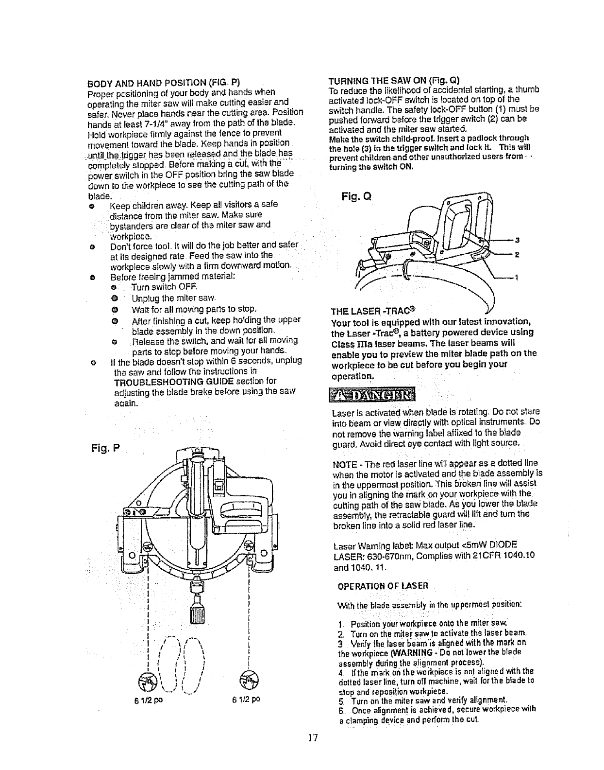
BODY AND HAND POSITION (FIG P)
Proper positioning of your bedy and hands when
operating the miter saw will make cutting easier and
safe_ Never p!ece hands near the cutting area. Position
hands at least 7-1/4" away from the path of the blade.
Hold workpiece firmly against the fence to prevent
movement toward the bfade. Keep hands in position
.untilthe.tr_gg_=rhas been released and the blade has
completely slopp_d Before rnal_ing ,_cut, _vit5 the .....
power switch in the OFF position bring the saw blade
down to the workpiece fo see the cutting path of the
blade.
•Keep children away. Keep all visitors a safe
distance from the miter saw. Make sure
bystanders are clear of the miter saw and
workplace°
eDon't force tool It will do the job better and safer
at its designed rate Feed the saw into the
workplace slowly with afirm downward mot.fen,
o Before freeing jammed material:
eTurn switch OFF.
a Unplug the miter saw,
@ Wait for all moving parts to stop,
@ After finishing a cut, keep holding the upper
blade assembly in the down position,
eRelease the switch, and wait for all moving
parts to stop before moving your hands
o 11the bfade doesn't step within 6 seconds, unplug
the saw and folIow the instructions in
TROUBLESHOOTING GUIDE section for
adjusting the blade brake before using the saw
aoain.
Fig. P
TURNING THE SAW ON (Fig, Q)
To reduce the likelihood of accidenta! starting, a thumb
activated lock-OFF switch is located on top of the
switcll handle, The safety lock-OFF button (1) must be
pushed forward before the trigger switch (2) can be
activated and the miter saw started.
Make the switch child-proof. Insert a padlock through
the hole {3) in the trigger switch and lock _L This will
prevent children and other unauthorized users from
turning the swttch ON,
THE LASER -TRAC _
Your tool is equipped with our latest innovation,
the Laser -Tree _, a battery powered device using
Class TI][a laser beams. The laser beams will
enable you to preview the miter blade path on the
workpteea to be cut before you begin your
operation,
Laser is activated when blade is rotating Do not stare
into beam or view directly with optical instruments, Do
not remove the warning label affixed to the blade
guard. Avoid direct eye contact with light source.
NOTE .The red laser line wilt appear as a dotted line
when the motor is activated and the blade assembly is
in the uppermost position. This b?oken line will assist
you in aligning the mark on your workpiece with the
cutting path of the saw blade. As you lower the blade
assembly, the retractable guard will llft and turn the
broken line into a solid red laser line.
Laser Warning label: Max output <5roW DIODE
LASER: 630-670nm, Complies with 2 tCFR 1040.10
and 1040° 11.
OPERATION OF LASER
With the blade assembly inthe uppermostpositient
tL r
®,
[
1
I
[
I
®
6lt2 po
1 Position yourwo_kpiece ontothe miter saw,
2. Turn on the m_tersaw to activate the laser beam.
3 Verify the laser beam i_ _ligned withthe mark on
the workplace (WARNING -Do not lower the blade
assembly duringthe alignment process).
4Ifthe mark on the workplaceis not aligned withthe
dotted laser Dine,turn oft machine, wait for the blade to
stop and repositionworkpiece
5. Turn on the miter saw and verifyalig nment.
6Once alignment is achieved, secureworkpiece with
aclampingdevice and perform the cut
]7
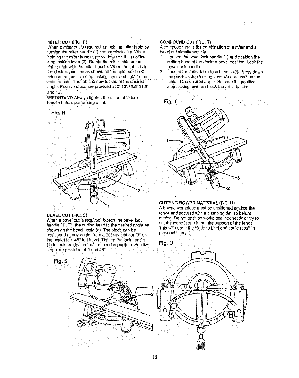
MITER CUT (FIG. R)
When a miler cut is required, un}ock the miler table by
tuming the miler handle (1) counterclockwise. While
holding the miler handle, press down on the positive
stop locking lever (2). Rotale lhe miler table to the
right c r Ieli with the miter handle. When the table is in
the desired positlon as shown on the miler scale (3),
release the positive slop locking lever and tight_n the
angle Positive slops are provided at 0°,15".22.5",3t 6"
and 45°_
IMPORTANT: Always lighten the miler table lock
handle before performing a cut.
COMPOUND CUT (FIG. T}
A compound cut is the combination of a miler and a
bevel cul simullanaausly.
1 Loosen 1he bevel lock handle (1] and position the
culting bead al lhe desired bevel posillon. Lock the
bevel lock handle.
2. Loosen the miler table lock handle (2) Press down
. _ positive slop (e_Wng laver.(3) and posWon .the
table aI the desired angle, Release the posilive
slop locking lever and lock the miter handle
Fig, T
Fig, R
I
BEVEL CUT (FIG. S)
When a beret cut is required, loosen the bevel lock
handle (1}. Till the culling head to the desired angle as
shown on the bevel scale (2). The blade can be
positioned at any angle, from a 90 _straight Cut (0° on
lhe scale) to a 45 ° left bevel, "l'ighlen the lock handle
(!) lo lock [he desired culling heed in position. Positive
slops are provided at0 and 45 _, . ._
CUTTING BOWED MATERIAL (FIG. U)
A bowed workplace must be posilioned against the
fence and secured with a clamping devise before
cutting, Do not position workplace incorrectly or try to
cut Ihe workp)ece without Ihe support ot the fence.
]'his will cause lhe blade to bind and could result in
personal injury.
Fig, U
18
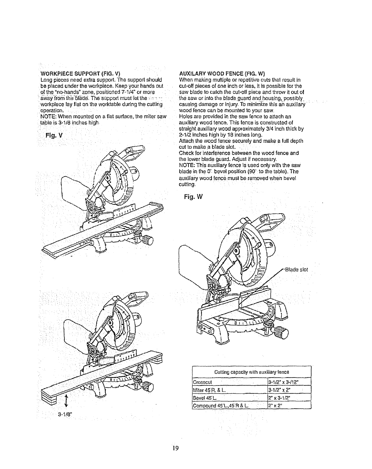
WORKP|ECE SUPPORT (FIG. V) AUXILARY WOOD FENCE (FIG, W}
Long pieces need extra support° The support should When making multiple or repetitive cuts thai result in
be placed under the workpiece. Keep your hands out cut-off pieces of one inch or less, it is possible ior the
of the "no,-hands" zone, positioned 7.o1/4"or more saw blade to catch the cut-otl piece and throw it out o!
a.wayli'0rn t_'6l_de, The Suppod must:iet the -._-__ the saw or into the blade guard and,hous{ng, p_ssib!y,.
Workp_ece lay flat on the worktabte during the cutting causing damage or injury. To minimize thls an auxilia_
operation.
NOTE: When mounted on a fiat surface, the miter saw
table is 3-1/8 inches high
Fig, V
wood fence can be mounted to your saw
Holes are provided in the saw fence to attach an
auxiliary wood _ence. This fence is constructed of
straight auxiliary wood approximately 3/4 inch thick by
2-1/2 inches high by 18 inches long.
Attach the wood tence securely and make a full depth
cut to make a blade slot.
Check for intederence between the wood fence and
the lower blade guard. Adjust if necessary.
NOTE: This auxiliary fence }s used only w_ththe saw
blade in the 0" bevel position (90" to the table)., The
auxiliary wood fence must be removed when bevel
cutting
Fig. W
\
3,1/8"
Cu_ting capacity with auxY[ia_ _ence
Crosscut _t2"
Miter 45'R. & L !3q12" x 2"
Bevel 45L. _1/2"
Compound 45'L.,45R & L, _2" x 2"
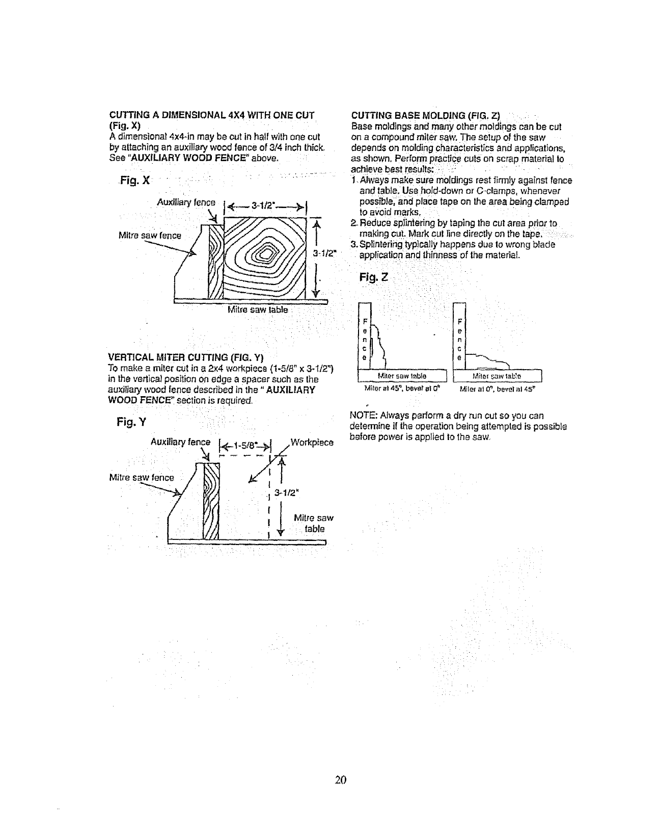
CUTTING A DIMENSIONAL 4X4 WITH ONE CUT
(Fig. X)
A dlmensiona,' 4x4-in may be cut in hail with one cut
by attaching an auxilia_ wood fence of 314 inch thick.
See "AUXILIARY WOOD FENCE" above=
Fig. X
CUTTING BASE MOLDING (FIG, Z)
Base me)dings and many other moldings can be cut
on a compOLmdmiter saw, The setup of the saw
depends on molding characteristics and appTications,
as shown. Perform practice cute on scrap materia! to
achieve best results;
": .... 1. Aiways make sure moldings rest firmiy against fence
and table. Use hoJd-down or C.clamps, whenever
3-1/2"---.-._1 possible, and place tape on the area being clamped
4,-- to avoid marks.
'_ 2. Reduce sp)intering by taping the cut area prior to
I making cuL Mark cut }ine direct}y on the tape,
3. Splintering typically happens due Io wrong blade
3..U2" application and thinness of the material
--.'--- } Fig.z
}
Mitre saw Gable
__F
ML_orsaw '_ab_o
Mtlor ia145'3,beV_" at C_' M{{Or at O_, bevel at 45"
Auxlilary fence
Mitre saw f._.,_ence/'_
IL
VERTICAL MITER CUTTING (RG. Y)
To make a miter cut in a 2x4 wod_piece (1-5/8" x 3-1/2")
in the vertica_position on edge a spacer such as the
auxiliary Wood fence described in the "AUXILIA RY
WOOD FENCE" section is required
Fig. Y
Auxiliary fen_ b,.1.Sf8- _ _
I Mitre saw
table
|, . l,
,Work,piece
NOTE: Always perform a dry run cut so you can
determine if the operation being attempted is possible
before power is applied 1othe saw.
2O
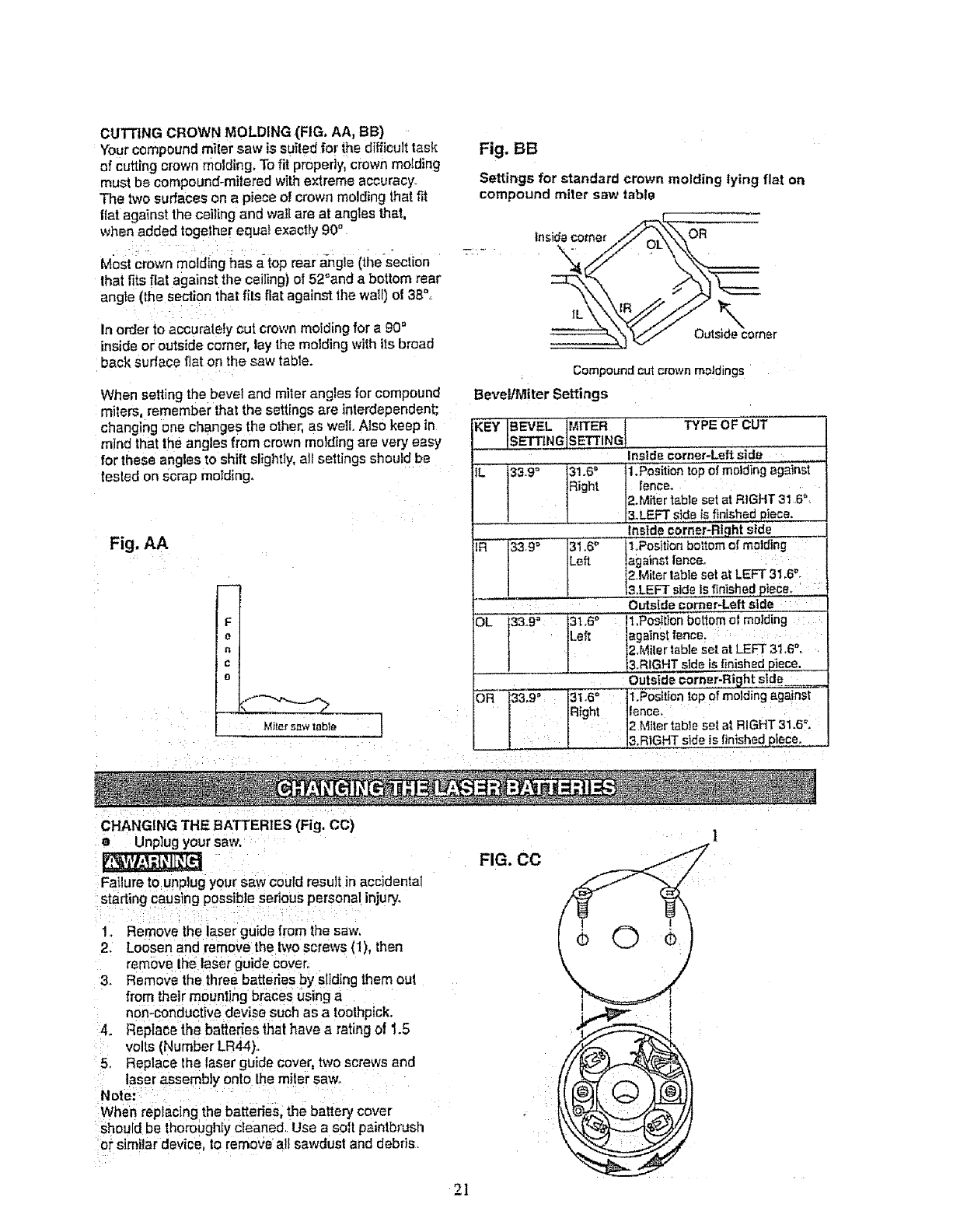
CUING CROWN MOLDING (FIG, AA, BB)
Your compound miler saw is suited for the difficult task
of cutting crown molding, To fit properly, crown molding
must be compound-mitered with extreme accuracy.
The two surfaces on a piece of crown molding that fit
fiat against the ceiling and wall are at angles that,
when added togelher equa! exactly 90" Inside comer OR
Most crown molding has a{op rear angle (the'secti0n ..... \
that fits fiat against the ceiling) of 52_and a bottom rear
angle (the section that fits flat against the wall) of 38°+
:: IL
In order to accurately cut crown molding for a 90 _ Outside comer
inside or outside comer, lay the molding with its broad
back sudace fiat on the saw table. Compound cut crown moldings
When setting the bevel and miter angles for compound Bevel/Miter Settings
miters, remember that the settings are interdependent;
changing one changes the other, as welt. Also keep in KEY IBEVEL" ]MITER l TYPE OF CUT
mind that the angles from crown melding are very easy _INGJS, ETTING
for these angles to shift slightly, nit settings should be . . . Inside corner.Left side
fesled on Scrap molding. IL 33.9_ 31.6D
Right
Fig. AA
F
e
n
C
o
.Mite_ 5RW l_b]_
Fig. BB
Settings for standard crown molding lying flat on
compound miter saw table
IR 33,9= 31.6_'
Left.
DL i33-9'_ 31.6°"":
[.eft
1,Pesiti0n top el molcling against
fence,
2,Miter table set at RIGHT 31.6 ",
&LEFT side ts finished piece,
Inside,col'net-Right side
1,Position bottom of molding
against fence,
2Miter table set at LEFT 31,6",
3.LEFT side is finished £bce,
Outside corner-Left,s!de :
1.Position bottom of melding :
against fence, :
2,Miler table set at LEFT 31,6'%
&RIGHT side is £nished piece.
Outside #orn£r-Right s!de
OR 1_3.9_ 31.6`_ 1.Position top of molding aga nst
1 Right fence. :
__Miter table set at RIGHT 31.6°.
_ 3,RIGHT sde s linished piece.
i : i
CHANGING THE BATTERIES (Fig. CC)
aUnplug your saw.
::Failure to:unplug your saw could result in accldenial
starling causing possible serious personal injury.
1_ Remove the laser guide from the saw.
2. Loosen and remove the two screws (1) then
remove lhe laser guide cover.
& Remove the three batterbs by sliding them out
from their mounting braces using a
n0n-:conductive devbe such as atoothpick.
4. Rep}ace:the batterie_thathave,_ ratirL_tof 1.5
volts (Number LR44)..
5, Replace the laser guide cover, two screws and
: laser assembly onto the miler saw.
:Note: : i: .... ........ '
:When replac(ng the batteries, the battery cover
should be thoroughly d_aned, Use a soft paintbrush
o_"similar device to remove all sawdust and debds.
FIG. CO
21
t
MAINTENANCE
DANGER
Never put lubricants on the blade while it is spinning.
To avoid fire or toxic reaction, never use gasoline,
naphtha acetone, lacquer thinner or simifar higllly
volatile solvents to clean the miter saw.
To avoid injury from unexpected starting or electrical
shock, unplug the power cord before working on the
saw.
For your safety, this saw is double4nsulated. To avoid
electrical shock, fire or injury, use only Darts identical
1othose identified tn the parts list Reassemble
exactly as the original assembly to avoid electrical
shock.
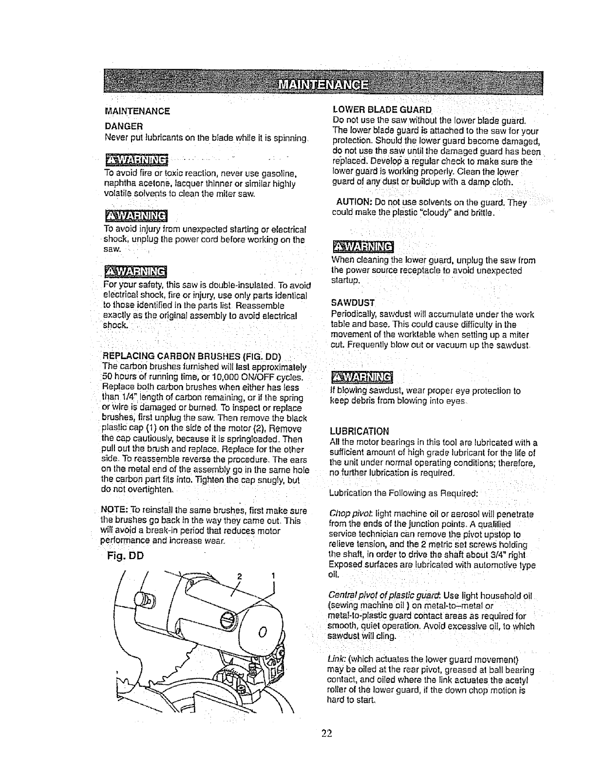
REPLACING CARBON BRUSHES (FIG. DO)
The carbon brushes furnished will lest approximately
50 hours of running lime, or 10,000 ONtOFF cycles.
Replace both carbon brushes v,,l_eneither has less
than 1/4' length of carbon remaining, or if the spring
or wire is damaged or burned, To inspect or replace
brushes, first unplug the saw. Then remove the black
plastic cap {1) on the side of the motor (2), Remove
the cap cautiously, because it is spdngtoaded.. Then
pull out the brush and replace, Replace for the other
side. To reassemble reverse the procedure.. The ears
on the metal end of the assembly go in the same hate
LOWER BLADE GUARD
Do not use the saw without the lower btade guard°
The lower blade guard is attached to the saw for your
protection. Should the lower guard become damaged,
do not use the saw until the damaged guard has been
replace& Develop a regular check to make sure the
lower guard is working properly. Clean the lower
guard of any dust or buildup with a damp cloth.
AUTtON: Do not use solvents on the guard. They
coutd make the plastic "cloudy" and briWe.
When cleaning the lower guard, unplug the saw from
the power source receptacle to avoid unexpected
startup.
SAWDUST
Periodically, sawdust wiil accumulate under the work
table and base. This could cause difficulty in the
movemenl of the worklable when setting up a miter
cut. Frequently blow out or vacuum up the sawdust
tf blowing Sawdust, wear proper eye protection to
keep debris from blowing into eyes
LUBRICATION
All the motor bearings in this tool are lubricated wilh a
sufficient amount of high grade lubricant for the life of
the unit under normal operating conditions; therefore,
no further lubrication is required.
the carbon part fits into. Tighten the cap snugly, bul
do not ovedighten. Lubrication the Following as Required:
NOTE: To reinslal! the same brushes, first make sure
the brushes go back in the way they came out. This
will avoid a break-in period that reduces motor
performance and increase wear.
Fig. DD
21
\\
0
Choppivot, light machine oil or aerosol wi]t penetrate
from the ends of the junction points. A qualilied
service technician can remove the PiVOtupstop to
relieve tension, end the 2 metric set screws holding
the shaft, in order to drive the shaft about 3[4" right
Exposed surfaces are Iubdcaled with automotive type
ell
Central pivot of plastic guar_ Use light household oil
(sewing machine oil ) on metal-to-metal or
metaI4o-pIestic guard contact areas as required for
smooth, quiet operation. Avoid excessive oil, to which
sawdust Will cling.
Link': (which actuates the lower guard movemenl)
may be oiled at the rear pivot, greased at ball beadng
contact, and oiled where the link actuates the acetyl
roller of the lower guard, ;f the down chop motion is
I_ard to start,
22
: i ¸¸/ :--::,; :/ s : ;= -; ...... : : - ::
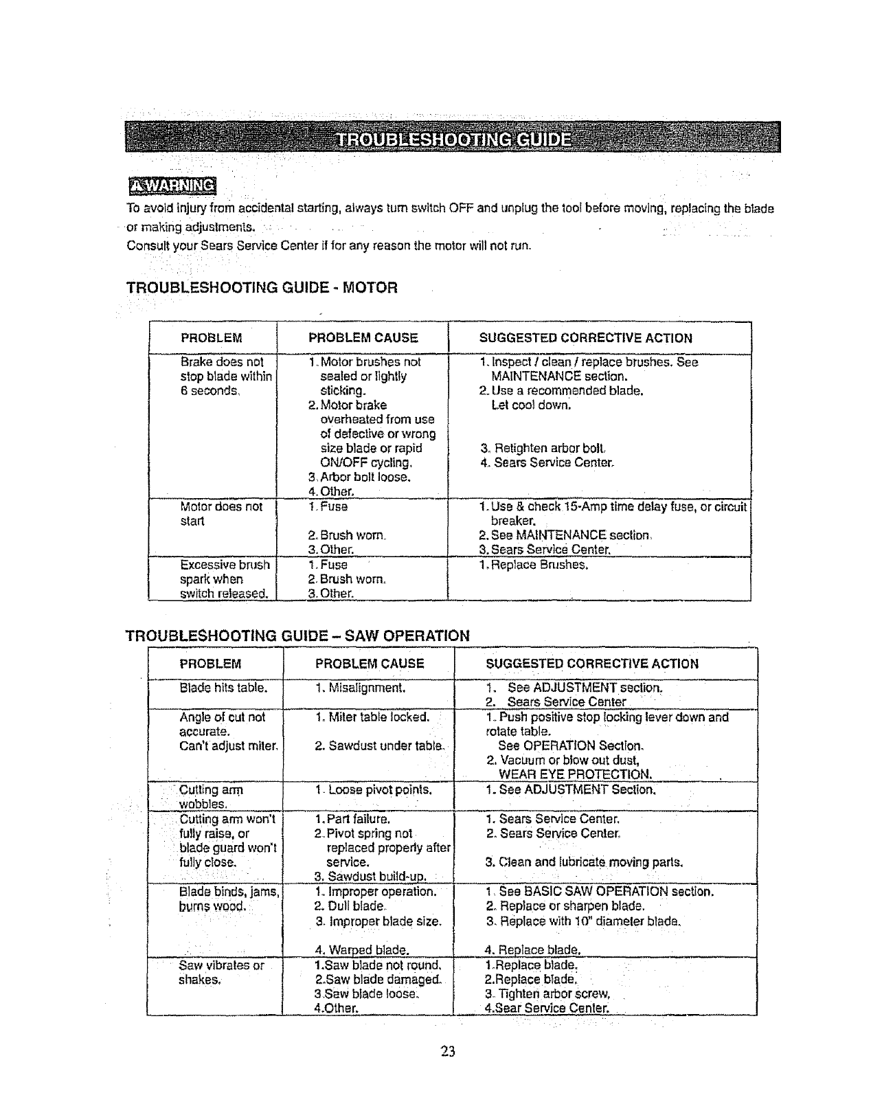
To avoid injury from accidental starting, always turn switch OFF and unp{ug the too! before moving, replacing the blade
or making adjustment. ....... : ....
Consult your Sears service Center if for any reason the motor will not run.
TROUBLESHOOTING GUIDE -MOTOR
PROBLEM
Brake does net
stop blade within
6 second&
PROBLEM CAUSE 1 SUGGESTED CORRECTIVE ACTION
1,Motor brushes not
sealed or lightly
sticking.
2. Motor brake
overheated from use
of defective or wrong
size blade or rapid
ON/OFF cycling,
3, Arborboltloose.
4. Other.
1. Fuse
1. Inspect !clean freplace brushes. See
MAINTENANCE section.
2. Use a recommended blade,
Let cool down.
& Retighten arbor boll,
4. Sears Service Center.
Motor does not 1. Use & check t 5-Amp time delay fuse, or circuit
start breaker.
2. Brush worn. 2. See MAINTENANCE section_
3. Other. 3. Sears Service Center.
Excessive brash 1. Fuse 1_Replace Brushes,
spark when 2. Brush worn.
switch released. 3. Other.
TROUBLESHOOTING GUIDE -SAW OPERATION
PROBLEM PROBLEM CAUSE SUGGESTED CORRECTIVE ACTION
Blade hits table. 1. Misalignment. 1. See ADJUSTMENT section.
2. Sears Service Center
Angle el cut not 1. Miler table locked. 1.,Push positive stop locking lever clown and
accurate, rotate table.
Can't adjust miter. 2. Sawdust under table. See OPERATION Section,
2, Vacuum or blow out dust,
WEAR EYE PROTECTION,
1. Loose pivot points. 1. See ADJUSTMENT Section,
1. Sears Service Center.
2. Sears Service Center,
Cutting arm
wobbles,
Cutting arm won't
fully raise, or
blade guard won't
fully close.
Bladebinds, jams,
g_rn$woad,
Saw vibrates or
shakes.
1. Part failure.
2. Pivot spring not
replaced propedy after
service.
3. Sawdust build-up.
1,,Improper operation.
2. Dull blade_
3. Improper blade size_
4, Warped blade.
1.Saw blade not round,
2.Saw blade damaged.
3.Saw blade loose.
4.Other.
3. Clean and lubricate moving parts.
1 SeeBASIC SAW OPERATION section,
2. Replace or sharpen blade.
3, Replace with 10" diameter btade.
4. Replace blade.
t_Replace blade.
2,Replace blade.
3. Tighten arbor screw.
4.Sear Service Center.
23
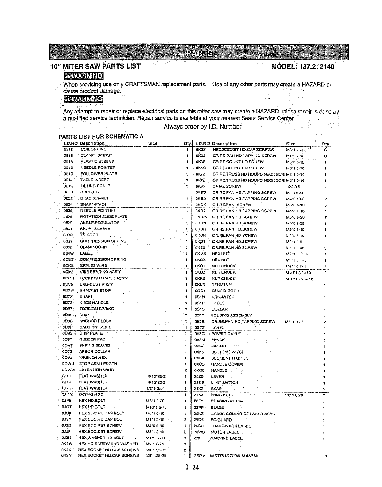
10" MITER SAW PARTS LIST MODEL: 137,212140
When servicing use onlyCRAFTSMAN replacement par|so Use of any other parts may create a HAZARD or
cause product damage,
Any attempt to repairor replace electrical partson thismiter saw may c_eateaHAZARDunIess repairis done by
a qua||fled servicetechnician, Repairservice is avai}able at your nearest Sears Service Centers
Always order by I.D, Number
PARTS LIST FOR SCHEMATIC A
LD.NO Description Siz.e
OBt 2 COIL SPRING 1
OBla CLAMP HANDLE 1
OBIA PLAST)C SLEEVE !
DBID NEEDLE POINTER 1
_IG FOLLOW_= R PLATE 5
O_IJ Ti_BLE INSERT '€
0B=K 31LT1NG SCALE 1
_-tU SUPPORT 1
DR21 BRACEET-T/LT i
LD.NO D¢_¢rtpf.lon Size Qty.
OK2S HE×_SOC}_"T HD.CAP SOREWB M_'l.ZB-20 3
BP_,J CRRE PAN HD TAPPING SCREW M._ "0.7-1(:( :3
Ol,_B CR I1E.COUt_T HO,SCR EW I',_5_0.8-12 I
O),_C CR BE COU_#T _'tD SCR EW M_I ,O+lo 1
0K'TZ CB RE,TRUSS HD ROUND NECK SCRI M5 _1_0d4 1
0KTZ CR R_LTRU_;S HB ROU_D NSCf; SCRI M_" 1 O14 I
oR9× DRIVE SCREW *:_2_3 5 2
OK_ CR nE PAN HD TAPPING SCJ3_V 1_4"10-_5 ,_
0){_D CR RE PA_ HD T/-_PPIhfG SCREW t/,_-'O IB._.5 2
D_24 EHAFT-P(VOI 1 GKCX CR.RE.PAN SCREW I_*,5"O,S 1D
0_26 NEEDLE POINTER _ 0){D: t CR _E PAN H0 T@PIh'G SC_=-%_I t_4"0 7 1() a
_:_2B ROIA'rIO,'_ _LIDE PLATE _ DKOM CR RE.PAN HO SCt_E'W t_5"0 B,'20 Z
0_,,?.9 AICGLE PEGBLATOR _ 0F, t}N cR_nE_PAN _IB,SCRF_W t/_.r_"[; _,25 1
0_1 SHAFT 5LF__VE t 0F.DR CR RE.PAN HD, SCREW _5'0 B_0
O_3S T_tOGER 1 01_DR CR.RE,PAN HD SCt4E_q M5°0_B-I{)
O£L3Y C;OMPRES_ION SPRING 1 DI{DT CR,REPAN HB SCREW M_'I {)-B
0_3Z CLAMP-CORD _ 0_ED CR.RE.PAP; HB,SCREW t_B'i 0-_{)
DB4W LABEL 0Kh'3 HEXNUT 1._,57 0'_=5
0C_S COMPRESSION _P_IlI_G O_QX )_E_ NUT I,'B'_ {) T=_
{)CK_ _PI_IN_ W_RS 0KO){ _JUT C_tUC_< _._S'_ ,O T_B
OOt,_Z V(BI_ O_t*.Rtt(_ A_ S'Y OKOZ NUT CHUCK !,110'( $ T=IO
DC_H LOCKI_,*G HANDLE AS5_'/
DCVS BAG-DUST ABB'Y
ODTW BRACKET S'_OP
_DTX _HAFT
0OTZ KNOB-HAP_DLE
0DB7 TORSION SPRING
{)[_10 SHIM
OO3B _CHOR BLOCK
{)D_FI CAUTION Lt_._ EL
BOS_ CH_P_ PLA_t_
0DR; RUBBER PAD
ODHT SPRING GUARD
0DTZ f,J3'3 0 R COLLAR
{)DVJ WRENCH HEX l
DDWLt _TDPASM LERGTH 1
_DWW F..XTF-_T_ON WING 2
0J_IJ FLAT WABHE(_ _10_20 2
OJ_.R FLAT WASHER _I_I{)'BO 3!
OJTR FLAT WASHER 112°_-315€ I
OJMM O_RING ROD 1
{L;PE HEX HD.BOLT M5"1J3_20 1
DJOT I(EX,HD,_OL_ MIO'i _-7S
{)JUK HEX_E{_.I(D.CAP BOLT l._,_'l 0 16
DJVY H_X S_.C.HD CAP BOLT M.5"l {)o16 2
OJZJg HE3r_DC.SET _GREV,t !,LB_O _IO
DJT_F HEX.SOC.SET BCR_V( t:AS'I.D* 1O 2
OJ"Z_ IIEX WASHER HD BOLT MO "1.?..5-2{)
20_O\V HEX HD SCRE_,V AND WASHBR M_-I (}o_5
{)K24 )4F..X $OCKE'_ HD CAP _CRE_._,'S MB'I 25.35 2
0K2N HEX SOCKET HD CAP SCREWS _ t_5-25 1
OKFt0 tqUT C( (UCR M12"1 75 T_I2
DKUX I'ERI_TNAL
{)QOI GUA_O-CQRI.3
BS1N AR)_MIT_R l
O_ 1P TABLE
0S1S COLLAR
{)SIT HOUBING ,_B_EMBL¥
OS2B CR RF-PAN HB ¸TAPPING SCREV_ M6"1 D-2_; 2
0BTZ LABEL
{)V_ P_WER _A_LE
{)V_ PENCE
OVgJ _,_OTOR
O_K9 BUT70_ BW_TCH
_KA SE_I_T _A_EL_
OXO5 HANDLE COVER
BXO_ HANDLE
20ZD LEVER
2tOg LIMIT SWITCH
211{2 B,¢_SE
2tK3 WING BOLT f,_,B"I 0-20
23E0 SRACI|qG PLAT_
23PP BLJ_D_
2-_|'_Z ARBOR C_LLAR OP LASER A_Y
25_5 PC GUARD
25Q0 TRADEoMARK LABEL
20V,YS |J:0"_ OR LABEL
27_L WARNING LA_EL
2ERV INSTRUCTION I;fAt,_UAL
24
• z
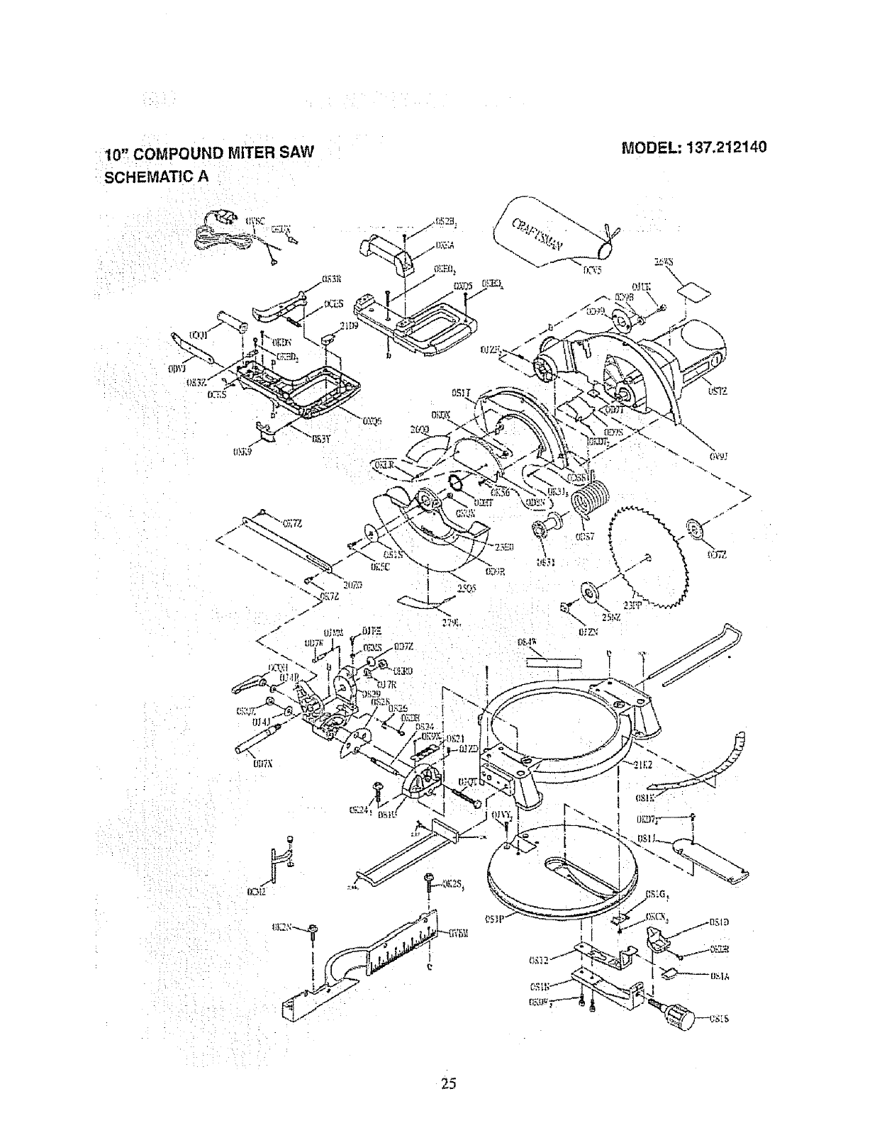
10'_ COMPOUND MITER SAW
:SCHEMATIC A
MODEL; 137.212140
4"
25
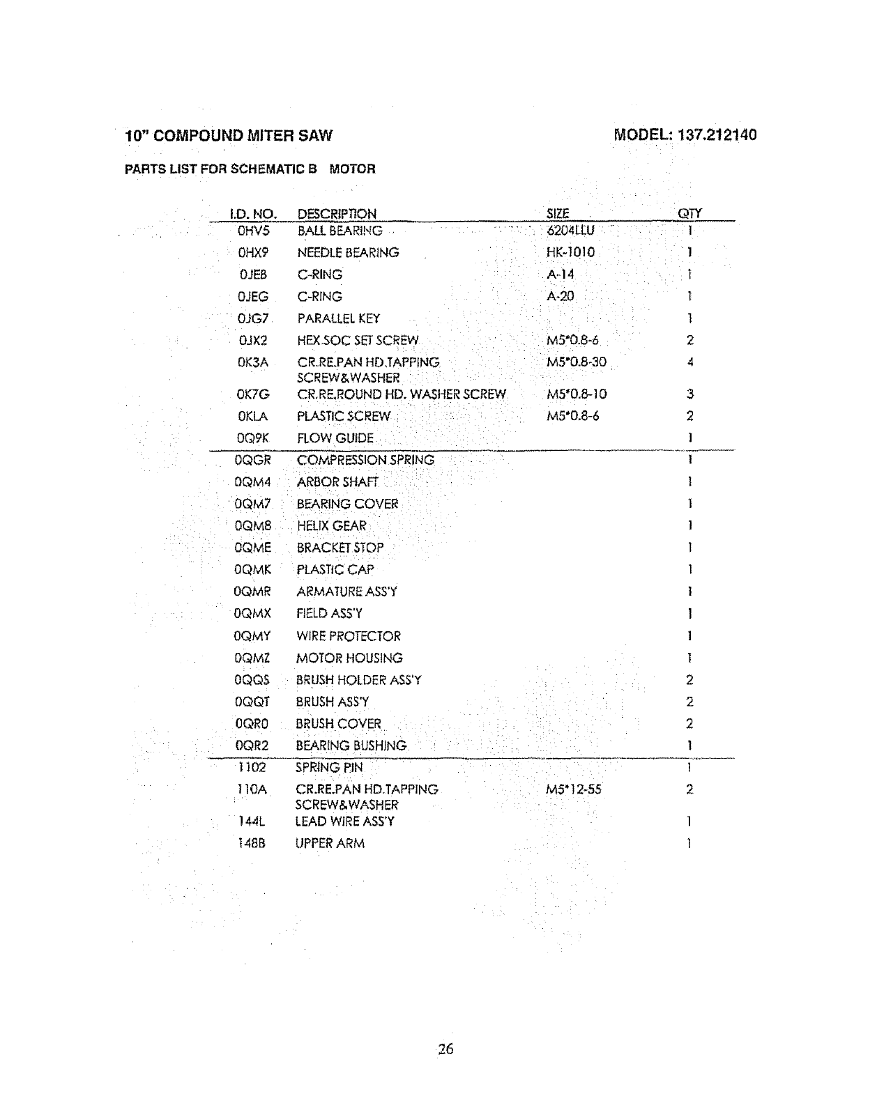
10" COMPOUND MITER SAW
PARTS LIST FOR SCHEMATIC B MOTOR
MODEL: 137.212140
I,D. NO.
0HV5
0HX9
OJEB
OJEG
0JG7
OJX2
0K3A
0K7G
OKLA
OQgK
0QGR
DQM4
0QM7
0QM8
0QME
0QMK
0QMR
0QMX
0QMY
OQMZ
OQQS
0QQT
0QR0
OQR2
1102
110A
! 44L
148B
DESCRIPTION
BALL BEARING
NEEDLE BEARING
C-RING
C-RING
PARALLEL KEY
HEX.SOC SETSCREW
CR..RE.PANHD°TAPPING
SCREW&WASHER
CR,RE,ROUND HD, WASHER SCREW
PLASTIC SCREW
FLOW GUIDE
COMPRESSION SPRING
ARBOR SHAFT
BEARING COVER
HELIX GEAR
BRACKET STOP
PLASTIC CAP
ARMATURE ASS'Y
FIELDASS'Y
WIRE PROTECTOR
MOTOR HOUSING
BRUSH HOLDER ASS'Y
BRUSH ASS'Y
BRUSH COVER
BEARING BUSHING
SPRING PIN
CR.RE.PAN HD,TAPPING
SCREW&WASHER
LEAD WIRE ASS'Y
UPPER ARM
SIZE
6204LEU
HK_]010
A,,14
A.20
MS=0.B-6
M5"0.8-30
M5° 12-55
QTY
1
l
l
1
2
4
3
2
i
I
l
1
1
1
I
i
l
]
l
2
2
2
l
l
2
I
!
26
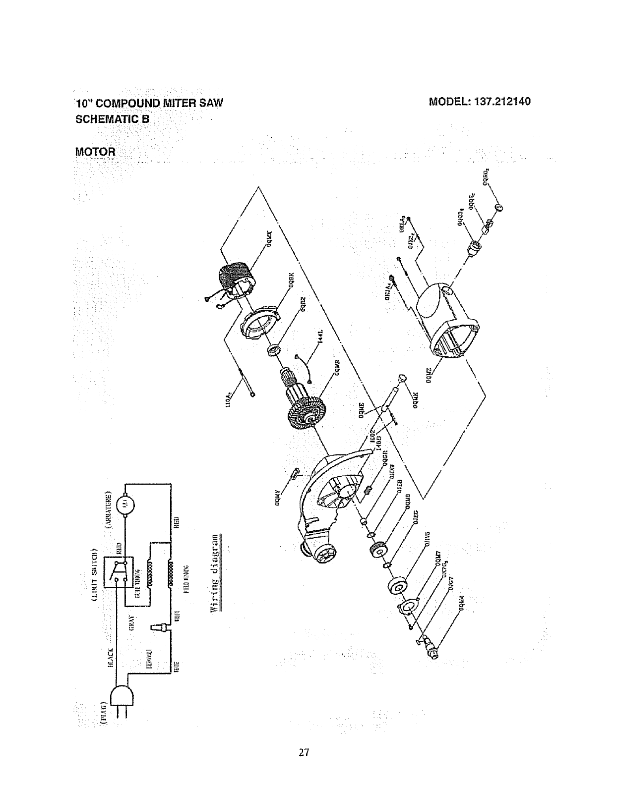
10" COMPOUND MITER SAW
SCHEMATIC B
MODEL: 137.212140
MOTOR
_()
Z
N_
\\
\
A
\
\
\\
L
g" /
/
/
/
/
/
27

Your Home
For repair-in your home-of all major brand appliances,
lawn and garden equipment, or heating and cooling systems,
no matter who made _t, no matter who sold it!
For the replacement parts, accessories and
Operator's Manuals that you need to do-it-yourself,
For Sears professional installation of home appliances
and items like garage door openers and water heaters.
1-800-4-MY-HOME e (1-800-469.4663)
Call anytime, day or night (U.S.A. and Canada)
wwwosears.corn www.sears.ca
Our Home
For repair of carry-in items like vacuums, lawn equipment,
and electronics, carl or go on-line for the location of your nearest
Sears Parts & Repair Center.
1-800-488-1222
Call anytime, day or night (U.S.A. only)
www.searsocom
L
To purchase a protection agreement on a product serviced by Sears:
1-800-827-6655 (U.S.A.) 1-800-361-6665 (Canada)
?:<?
2;i;:;
Para pedir servicio de reparaci6n
a domicilio, y para ordenar piezas:
1-888-SU-HOGAR _'
(1-888-784.6427)
Au Canada pour service en fran;ais:
1-800-LE-FOYER ;'_c
(! -800-533-6937)
www.sears.ca
Reg_sler_d Trad_.mad_ttM Trademark I_Scr_ Mork o! Scat% Roebu._.__nd Co.
@M_¢_ Re_si_d_ It_ I_rc_ _ F_r_,._ !r_ Mar¢_ de Ss¢,,4_oda S_ats.Roebt_ckt_nd Co
_c M_tque d_ comme_ce /_ M_que d_pos6e de Seats, Rceh.uck _d Co.
_,_;ii:il_I_/! ii<:_> i _i ...... ;/
S_,_rs, Roebud_and Co.
