Craftsman 137212940 User Manual MITER SAW Manuals And Guides L0812511
CRAFTSMAN Miter Saw Manual L0812511 CRAFTSMAN Miter Saw Owner's Manual, CRAFTSMAN Miter Saw installation guides
User Manual: Craftsman 137212940 137212940 CRAFTSMAN MITER SAW - Manuals and Guides View the owners manual for your CRAFTSMAN MITER SAW #137212940. Home:Tool Parts:Craftsman Parts:Craftsman MITER SAW Manual
Open the PDF directly: View PDF ![]() .
.
Page Count: 15
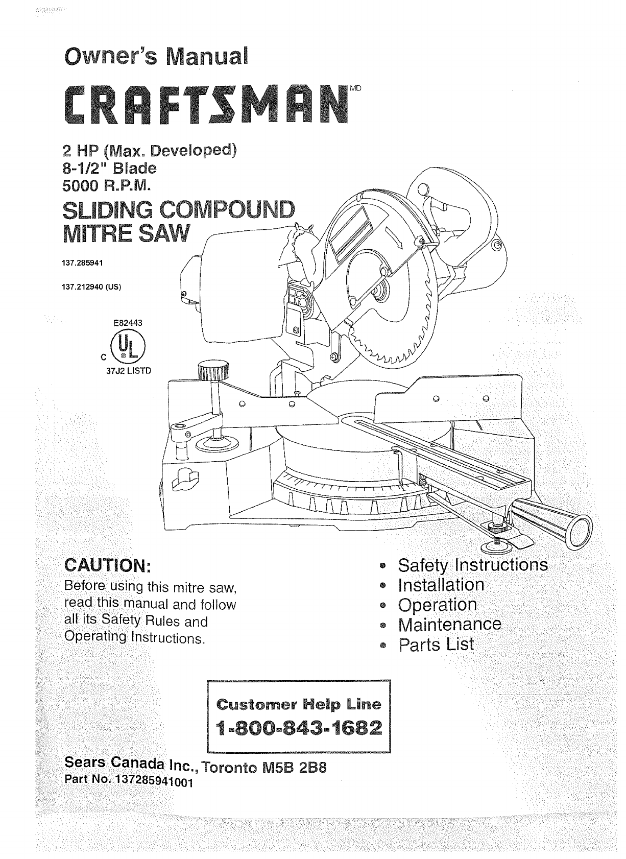
Owner's anual
IVlD
137.285941
137.212940 (US)
E82443
37J2 LISTD
:v /: •L •: : : ¸I¸:I :
•_i_!" _:_/ _,i _'_:;_<_
_:•i:¸¸::?ii!:: ,•::::_•:_:_•:,,i:
sing this mitre saw,
_:::: read th iS _manua and follow
and
nstructions.
i
, Safety In
o Installation
,, Operation
o Maintenance
o Parts List
Lions
Customer HeJp Line
1-800=843°1682
Inc., Toronto M5B 288
)41001
SECTION PAGE
War_a_y ................................................................... 2
Product Specifications ...................................................... 2
Safety Instructions ............................................................ 3
Accessories and A'_tachrnen_s ................................................. 8
Carto_1 Conten__s ........................................................... 8
Know Your SHding B)_itre Saw .................................................. !0
Giossary of _rer.ms ......................................................... 11
.Assemb@" and Adiustments ................................................. 12
Operation ................................................................ 20
_ltainte_ance ............................................................ 26.
Troubieshoo_.ing guidr_ ...................................................... 27
Parts .................................................................. 28
FULL TWO YEAR WARRANTY
If this product fails due to a defect in rnatenal or workmanship within two years from [he date of purchase. Sears
will at its option repair or replace it free of charge.
Contact a Sears Service Center for repair.
f If [his products !s used for commerctal or rental purposes, this warranty applies only for 90 days from the date
of purchase.
This warranty _sin addition to any statutory warranty.
l Sears Canada _nc., Toronto M5B 2B8
MOTOR
Power source ..........
Horsepower ...........
Speed ...............
Brake ................
Double insulateci .......
CUTTING CAPACFY
0° Mkre - 0° Bevel ......
45° Mitre - 0° Bevel ....
0° Mitre - 45° Bevel .....
450 Mitre - 450 Bevel ....
MITRE DETENT STOPS ....
BEVEL POS_TSVESTOPS ..
CARRIAGE SYSTEM ......
120V AC, 60 HZ, 10 AMPS
2 HP (Max. Developed)
5000 R.RM.
Electric
Yes
2-5/8" x 12"
2-5/8" x 8-1/2"
! -3/4" x 12"
1_3/4"x 8-!/2"
0, 15, 22.5, 31.6,
45 ° R & L. 60_ R
0 °, & 450 L
3 Rail, ball bearing slide
BLADE S_ZE ............. 8-1/2"
ARBOR SIZE ............ 5/8"
TABLE D_AMETEP, ........ 10-1/2"
BASE S_ZE ............. 20-3/4" x 12"
DUSi" COLLECTION ....... Yes
VISE CLABJ_P ............. Yes
To avoid electnca! hazards, fire hazards, or damage to
the tool, use proper circuit protection.
Your sliding mitre saw is wired at the factory for 120V
operation. Connect to a 120V, 15 AMP time delay [use or
circuit breaker. To avoid shock or fire, replace power cord
immediately tfit is worn, cut or damaged in any way.
GEMER_-_L SAFETY _'_,->TRUCT, uN_
BEFOR,... USING TF-_ESUDING _'_TRE SAW
Safety is a combination of common sense, szaying alert
and knowing how [o use yobr n1_[i-esaw.
To avoid mistakes thai could cause serious injury, do not
plug Ihe mitre saw in until you have read and understood
the following:
I2.
!. READ and become familiar with this entire instruction
manual. LEARN [he tool's apphcalions, limilations, and
possible hazards, t 3.
2. KEEP GUARDS mNPLACE and in working order. 14.
3. REMOVE ADJUSTING KEYS AND WRENCHES.
Form the habit of checking to see that keys and
adjusting wrenches are removed from the tool before
turning ON. !5.
4. KEEP WORK AREA CLEAN° Cluttered areas and
benches invite accidents.
.
,
7.
,
.
!0.
DON'T USE _N A DANGEROUS ENVIRONMENT.
Don't use power tools in damp or wet locations, or
expose them to rain. Keep work area welt lighted.
KEEP CHILDREN AWAY. All visitors should be kept at
a safe distance from the work area.
_V_AK-=WORKSHOP KID PROOF with padlocks, master
switches, or by remowng starter keys_
DON'T _-_
r.JRCE THETOOL. It will do the job better
and safer at the rate for which it was designed.
USE THE R_GHTTOOL. Dont force tool or the
attachment to do a job for which it was not designed.
USE PROPER EXTENSION CORD. Make sure your
exiension cord is in good condition. When using an
extension cord, be sure to use one heavy enough to
carry the current your product will draw. An undersizecl
cord wilf cause a drop in Iine voltage resulting in loss
of power and overheating. The table on page 7 shows
the correct size to use depending on cord length and
nameplate ampere rating. If in doubL use the next
heavier gauge. The smaller the gauge number, the
heavier the cord.
WEAR PROPER APPAREL. DO NOT wear loose
clothing, gloves, neckties, rings, bracelets, or other
jewelry which may get caught in moving parts.
Nonslip footwear is recommended. Wear protective
hah covenng [o contain long hair.
SAVE THESE
11,
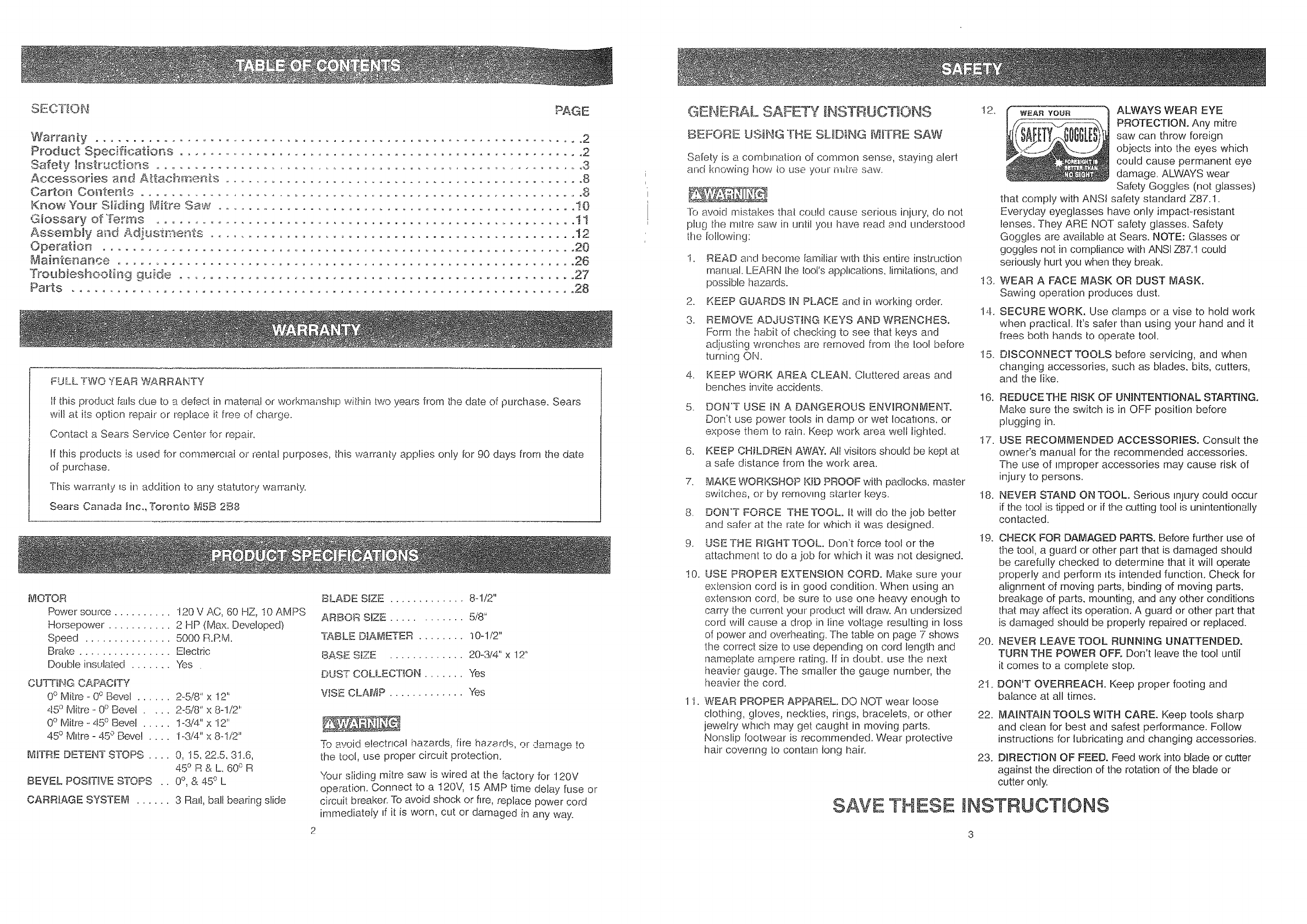
WEA_YOU_ ALWAYS WEAR EYE
PROTECTION. Any mitre
saw can throw foreign
objects into the eyes which
could cause permanent eye
damage. ALWAYS wear
Safety Goggles (not glasses)
that comply with ANSi safety standard Z87.1.
Everyday eyeglasses have only impact-resistant
lenses. They ARE NOT safety glasses. Safety
Goggles are available at Sears. NOTE: Glasses or
goggles not in compliance wiLhANSI Z87.1 could
seriously hurl you when they break.
WEAR A FACE MASK OR DUST MASK.
Sawing operation produces dust.
SECURE WORK. Use clamps or a vise to hold work
when practical. It's safer than using your hand and it
frees both hands to operate tool.
DISCONNECT TOOLS before servicing, and when
changing accessories, such as blades, bits, cutters,
and the like.
16.
17.
18.
REDUCE THE RISK OF UNINTENTIONAL STARTING,
Make sure the switch is in OFF position before
plugging in.
USE RECOMMENDED ACCESSORIES. Consult the
owner's manual for the recommended accessories.
The use of improper accessories may cause risk of
injury to persons.
NEVER STAND ON TOOL, Serious injury could occur
if the tool is tipped or if the cutting tool is unintentionally
contacted.
I9.
20.
2t.
CHECK FOR DAMAGED PARTS. Before further use of
the tool, a guard or other part that is damaged should
be carefully checked to determine that it will operate
properly and perform _tsintended function. Check for
alignment of moving parts, binding of moving parts,
breakage of parts, mounting, and any other conditions
that may affect its operation. A guard or other part that
is damaged siqould be properly repaired or replaced.
NEVER LEAVE TOOL RUNNING UNATTENDED.
TURN THE POWER OFF, Don't leave the too! until
it comes to a complete stop,
DON'T OVERREACH. Keep proper footing and
balance at all times.
22.
23.
MAINTAIN TOOLS WITH CARE. Keep tools sharp
and clean for best and safest performance. Follow
instructions for lubricating and changing accessories.
DIRECTION OF FEED. Feed work into blade or cutter
against the direction of the rotation of the blade or
cutter only,
NSTRUCT ONS

24. DO NOT operate the tool if you are under the influence
of any drugs, alcohol or medication that could affect
your ability to use the tool properly.
25. Dust generated from certain materials can be
hazardous to your health. Always operate tile mitre saw
in a well-ventilated area and provide for proper dust
removal Use dust collechon systems whenever
possible.
SPECIFIC SAFETY mNSTRUCTBONS
FOR SLIDtNG MBTRE SAWS
1. READ AND UNDERSTAND all safety instructions
and operating procedures throughout the manual.
2. DO NOT operate the mitre saw until it is completely
assembled and ,lstalled according to the instructions.
3. SHOULD any part of your mitre saw be missing.
damaged, or fail in any way, or any electrical
component fall to perforrn properly, shut off the switch
and remove the plug from tile power supply outtel
Replace missing, darnaged, or failed parts before
resuming operation
4. IF YOU ARE NOT thoroughly famdlar with the
operation of mitre saws, obtain adwce Irom your
supervisor, instructor, or other qualified person.
5. NEVER CARRY the tool by the cord or the cutting
head handle. Damage to the insulation could cause
electric shock. Damage to the w_re connections could
cause a fire.
6. SERIOUS INJURY could occur if the tool tips over or
you accidentally hit the cutting tool. Do not store
anything above or near the tool.
7. AVOID INJURY from unexpected saw movement.
Place the saw on a firm level surface where the saw
does not rock, and bolt or clamp the saw to its support.
8. BEFORE MOVING the saw. lock the mitre, bevel, and
cutting head positions.
9. CHOOSE the right 8-1/2" diameter blade for the
material and the type of cutting you plan to do. Never
use blades larger or smaller in diameter than
recommended.
10. USE ONLY CROSSCUTTING SAW BLADES. Do not
use blades with deep gullets as they can deflect to
the side and contact the guard.
11. USE only blade collars specified for your saw. The
recessed sides must face the blade.
12. USING THE HEX BLADE WRENCH supplied, make
sure the arbor screw is firmly tightened.
t3. NEVER USE the saw without the cover plate securely
in place, tt keeps the arbor screw from fa!ling out if !t
accidentally loosens, and prevents the spinning blade
from coming off the machine.
SAVE THESE
14. KEEP HANDS out of the path of the saw blade. If the
workpiece you are cutting would cause your hand to
be within 6-1/2 inches of the saw blade, the workplece
should be clamped in place before makHlg the cut.
15. MAKE SURE the blade and collars are clean and
properly arranged. After installing a new blade, make
sure the blade clears the table slot at the 0° and 45°
bevel positions. Lower the blade tnto [he table slot and
check for any contact with the base or turn table
structure, tf the blade contacts tile table, see the
TROUBLESHOOTING GUIDE for "depth stop
adjustment" or contact the Sears Service Centre.
Broken saw parts could injure you or others.
16. ALWAYS check the blade for cracks or damage
before operation. Replace a cracked or damaged
blade irnmediately.
17. USE blades recommended at 5000 RPM or greater.
18. ALWAYS keep the blade guards in place.
19. TO KEEP the nut from working its way off as you use
the saw. at teast one thread of the pivot bolt must
always shck out past the nut. Always keep the nut at
least that tight.
20. FAILURE TO TIGHTEN the jam nut could let the depth
stop slip and let the blade strike the saw table.
Broken saw parts could injure you or others.
21. CLEAR EVERYTHING except the workpiece and
related support devices off the table before turning
the mitre saw on.
22. MAKE SURE all clamps and locks are tight and
there is no excessive play in any part.
23. ALWAYS MAKE SURE all handles are tight before
cutting, even if the table is positioned in one of the
positive stops.
24. MAKE SURE there are no nails or foreign objects in
the part of the workpiece to be cut.
25. MAKE SURE the blade is not contacting the workpiece
before the switch is turned on.
26.
27.
28.
ALWAYS hold the work firmly against the fence and
table. DO NOT perform any operation freehand.
DO NOTTRY TO CUT SHORT PIECES. You cannot
properly support the workpiece and keep your
hold-down hand the required distance from the blade.
ALWAYSTIGHTEN THE CLAMP so that the workpiece
is secured between the clamp and fence or base. No
visible gap should be present between saw and wood.
29. NEVER cut metals or masonry. Because of the
sliding action of the saw, this machine is not designed
for cutting metals. Use this mitre saw to cut only wood
and woodlike products. Other materials may shatter,
bind on the blade, start fires or create other dangers.
30. NEVER reach around the saw blade.
INSTRUCTIONS
31. TO AVOID POSSIBLE PERSONAL INJURY of
damage to the miter saw due to tipping, do not
operate the saw without the support bracket
securely in position.
32. NEVER PULLTHE SAW toward you during a cut.
The blade can suddenly climb Lip on top of the
workpiece and force itself toward you.
33. ALLOW the motor to come up to full speed before
starhng CLIt.
34.
35.
36.
KEEP the motor air slots clean and free of chips.
NEVER apply lubricants to the blade when it is
running.
MAKE SURE the blade has come to a complete stop
before removing or securing the workpiece, changing
the workpiece angle, or changing the angle of the
blade.
37. NEVER use the mitre saw in an area with flammable
liquids or gases.
38. NEVER use solvents to clean plastic parts. Solvents
could possibly dissolve or otherwise damage the
material.
39. ALWAYS PERFORM DRY RUNS. Make sure the saw
Jsunplugged. Completely set up your saw. Pull the
blade and cutting head through the full range of motion
to check for interference. The clamp can be used in
a left or right configuration. Make sure that your blade,
saw guard or motor does not interfere with the clamp.
Correct any interference before use.
40. PLAN HOW YOU WILL MAKE THE CUT:
MAKE SURE the blade is not spinning.
RAISE the blade.
• SLIDE the saw out above the front edge of the
workpiece before starting the saw.
• PUSH the saw blade down on top of the wood and
back toward the rear of the saw to make the cut_
BE
41.
42.
43.
FORE EACH USE
INSPECT YOUR MITRE SAW.
D!SCONNECTTHE MITRE SAW. To avoid injury from
accidental starting, unplug the saw before changing
the setup, changing the blade, or adjusting anything.
Compare the direction of the rotation arrow on the
guard to the direchon arrow on the blade. The blade
teeth should always point downward at the front of the
saw. Tighten the arbor screw. Tighten the cover plate
stop screw.
CHECK FOR DAMAGED PARTS. Check for:
PROPER alignment of moving parts
DAMAGED electric cords
-_ BINDING of moving parts
o BROKEN parts
, STABLE mounting
SAVE THESE
44.
45.
46.
FUNCTION of arm return spring and lower guard:
Push the arrn all iEheway down, then let it rise
up until it stops by itself. Check the lower guard
to see it it closed fully_ If it did not, follow the
insiEructionsin the TROUBLESHOOTING GUIDE.
o SMOOTH, solid movement ot:sliding assembly.
o OTHER conditions that may affect the way the
mitre saw works. II any part of the m_tre _s
rniss_ng, bent, or broken in any way, or any
electrical parts don't work, turn the saw o1:1and
unplug it. REPLACE damaged, missing, or faded
parts before using the saw again.
KEEP GUARDS IN PLACE, in working order, and in
proper adjustment. Maintain tools with care.
Keep the mitre saw clean for best and safest
performance. Follow instructions for lubncahng.
DON'T put lubricants on the blade wh!le it's spinning
REMOVE adjushng keys and wrenches from the tool
before turning it on.
TO AVOID INJURY FROM JAMS, SLIPS, OR
THROWN PIECES:
o USE ONLY RECOMMENDED ACCESSORIES.
Consult this Owner's Manuat for recommended
accessories. Follow the instructions that come
with the accessories. The use of improper
accessories may cause risk of injury to persons.
°MAKE SURE the blade is sharp, undamaged,
properly aligned and free of vibration. With the
saw unplugged, push the cutting head all the way
down. Hand spin the blade and check for
clearance. Tilt the cutting head to a 45 degree
bevel and repeat the check. If the blade hits
anything, see the TROUBLESHOOTING GUIDE
for "depth stop adjustment", or contact your
Sears Service Centre.
47. PLAN HOW you will hold the workpiece from start
to finish:
o AVOID awkward operations and hand positions
where a sudden slip could cause fingers or
hand to move into the blade.
o DON'T OVERREACH. Keep good footing and
balance.
KEEP your face and body to one side of the
saw blade, out of line with a possible throwback.
o NEVER CUT FREEHAND:
- BRACE your workpiece solidly against the fence
and table top so it will not rock or twist during
the cut.
- MAKE SURE there is no debris between the
workpiece and its supports,
- MAKE SURE no gaps between the workpiece,
fence and table will let the workpiece sh_ft after
it is cut in two,
"- CUT only one workpiece at a time.
KEEP the cut off piece free to move sideways
after it is cut off. Otherwise it could get wedged
against the blade and be thrown violently.
iNSTRUCTIONS
4 5

CLEAReverythingexcepttheworkpieceand
relatedsupportdevicesofftheworktablebefore
turningthemitresawon.
o SECUREWORK.Useclampsora viseto hetp
holdtheworkwhenit _spractical.
48. USE EXTRA CAUTION with large, very small or
awkward workpieces:
o USE extra supports (tables. saw horses, blocks,
etc.) for any workpieces large enough to tip
when not held down to tile table top.
o NEVER use anoiher person as a substitute for a
table extension, or as additional support for a
workpiece that is longer or wider than the basic
m_tre saw table, or io help feecl, support or pull
the workpiece.
o DO NOT USE this saw to cut pieces too small to
let you easily hold the work.
* WHEN CUTTING irregularly shaped workpieces,
plan your work so it will not slip and pinch the
blade and be torn from your hands. A piece of
molding, for example, must lie flat or be held by
a fixture or jig that will not let it twist, rock or slip
while being cut.
oPROPERLY SUPPORT round material such as
dowel rods, or tubing. They have a tendency to
roll while being cut, causing the blade to "bite".
To avoid this, always use a fixture designed to
properly hold your workpiece.
WHEN THE SAW IS RUNNmNG
49. BEFORE STARTmNG your cut, watch the mitre saw
while it runs. If it makes an unfamiliar noise or
vibrates a lot, stop immedJately. Turn the saw OFR
Unplug the saw. Do not restart unbl finding and
correcting the problem.
50. KEEP CHBLDREN AWAY. Keep a!l visitors a safe
distance from the mitre saw. Make sure bystanders
are clear of the mitre saw and workpiece.
51. LETTHE BLADE reach full speed before cutting.
This will help avoid thrown workpieces.
52. DON'T FORCE THE TOOL. tt will do the job better
and safer at its designed rate. Feed the saw into the
workpiece only fast enough to let the blade cut without
bogging down or binding.
53. BEFORE FREEING JAMMED MATERIAL:
, TURN mitre saw OFF by releasing trigger switch.
WAmTfor all moving parts to stop.
• UNPLUG the mitre saw.
54. AFTER FINISHmNG A CUT:
o KEEP holding the cutting head down.
RELEASE the switch, keeping the cutting head
down, and walt for all moving parts to stop before
moving your hands.
SAVE THESE
o iF BLADE doesn't stop within 6 seconds, unplug
the saw and foltow ihe instructions in the
TROUBLESHOOTING GUIDE for iixlng the blade
brake before using the saw again.
55. BEFORE LEAVING THE SAW:
NEVER LEAVE the tool runnnlg unattended.
Turn Ihe power OFR WaR for all moving parts
to stop.
o iWAKE WORKSHOP child proof. Lock the shol:_
Disconnect master swdches. Store the tool away
from childron and others not quahfied [o use the
tool.
56. NEVER unplug the saw with the switch in _lle ON
posibon.
57. DISCONNECT the saw from the power source and
clean the machine before leaving if. MAKE SURE [he
work area is clean before leaving the machine.
ELECTRICAL REQU RE[v E .
POWER SUPPLY AND MOTOR
SPECiFiCATiONS
The AC motor used in this saw is a universal, nonreverspble
type. See "MOTOR" in the PRODUCT SPECIFICATIONS
section on page 2.
To avoid electrical hazards, fire hazards, or damage [o lhe
tool, use proper circuit protection. Your saw is wired at the
factory [or 120V operation. Connect to a 120V, 15 Amp
circuit and use a 15 Amp time delay fuse or circLntbreaker.
To avoid shock or fire, if power cord is worn or cut, or
damaged in any way, have it replaced immediately.
DOUBLE _NSULATED
The mitre saw is double insulated to provide a double
thickness of insulabon between you and the tool's electncal
system. All exposed metal parts are isolated from the
internal metal motor components with protecbng insulation.
Replacement parts - When servicing use only identical
replacement parts.
Polarized plugs - This saw has a plug that looks like the
one shown below:
To reduce the risk. of electrical shock, _his saw has a
polarized plug (one blade is wider than the other). _hls
plug will Ii[ m a polarized ouile[ only one way. II the plug
does no! fit [u!ly Jn Ihe outlet, reverse the piug. it Rstill
does not fit, contact a qualified electrician to mslall the
proper outleL Do not chan.ge the plug in any way.
Double insulation does not take the place ol normal safety
precautions when operabng [!_is tooi.
To avoid electrocution:
i. Use only identical repiacement parts when serwcmg a
toot with double insulation. Servicing should be
pel!ormecl by a qualit:iedtechnician.
2. Do not use power tools in wet or damp areas or
expose them to rain.
This !ool is intended for indoor use only.
MOTOR SAFETY PROTECTION
IMPORTANT: -Foavoid motor damage, l.his motor
should be blown out or vacLIumed frequently to keel)
sawdust from interfering with normal motor ventilation.
.
.
.
4.
CONNECT [his tool to a 120V, 15 Amp branch arcuit
with a 15 Amp [!me delay fuse or cwcuit breaker.
Using the wrong size fuse can damage the motor.
tF the motor won't start, release the trigger switch
immediately. UNPLUG TIdE TOOL. Check the saw
blade to make sure it turns freely. !i:the blade is free.
try to start the motor again. If the motor still does not
start, refer to the TROUBLESHOOTING GU_'DE.
IF [he motor suddenly stalls while cutting wood.
release the [rigger switch, unplug the too!, and free
the blade from [he wood. The saw may now be
restarted and the cut finished.
FUSES may "blow" or circuit breakers may trip
frequen!ly it:
a. MOTOR is overloaded. Overloading can occur il:
you feed [oo rapidly or make [oo many start /
stops in a short brae.
b. LINE VOLTAGE is more than 10% above or
below the nameplate voltage. For heavy loads,
however, the voltage at motor terminals must
equal the voltage specified on the nameplate.
c. iMPROPER or dutl saw blades are used.
5. MOST motor troubles may be traced to loose or
incorrect connections, overload, iow voltage (such as
small size wire in the supply circuit) or to overly long
supply circuit wire. Always check iEheconnechons, the
load and [he supply clrcufl if the motor doesn't work
well. Check wire sizes and teng[lq with the Extension
Cord Chnr[ below.
GUIDELINES FOR EXTENS_OI1 CORDS
USE PROPER EXi'E_\_S_ON CORDL Make sure yOLW
extension cord is in good condibon. When using an
extension cord, be sure [o use one heavy enough to carry
the current your procluc[ will draw. An undersized cord will
cause a drop in !ine voltage, resulting in loss of power and
cause ovedqeating. The table below shows the correci size
to use depending on cord length end nameplate ampere
rahng. I1:in cloubt, use tlqe next heavier gauge. The smaller
the gauge number, the heavier _he cord.
Be s_._reyour extension cord is properly wired and m
good condition. Always replace a damaged extension cord
or have it repaired by a qualified person before using it.
Protect your extension cords from sharp objects, excessive
tqea[ and damp or wet areas.
Use a separate electrical circuit for your tools. This cwcuit
must not be less than #12 wire and should be protected
with a !5 Amp time lag fuse. Before connechng the motor
to the power line, make sure the switch is m the OFF
position and the electric current is rated the same as the
current stamped on the motor nameptaie. Running at a
lower voltage will damage the motor.
(when using 120 volts onfy_
Ampere Rating ! Tota_ ienglh of cord in fee__
mo_e than not mare than T 25' 50' ] 00' 150'
4-
0 6 ! _8 i6 !6 14
6 10 I 18 16 14 12
10 I2 I 16 16 14 1212 16 14 12 Not _ecommended
CAUTION: In all cases, make certain the receptacle in
question is properly groLmcled. If you are not sure have a
certified electrician check the receptacle.
Tt_is sliding mitre saw is for indoor use only. Do not
expose to rain or use in damp locations.
SAVE THESE _NSTRUC 0iONS
6 7

PROHJBBTED ACCESSORIES
Use only accessories recommended for this sliding mitre
saw. Follow Instructions that accompany accessories.
Use of improper accessories may cause hazards_
Tile use of any cutttng tool except 8-1/2 inch saw blades
which meet the reqLHrements under recommended
accessories is prohibited. Do not use accessories such as
shaper cutters or dado sets. Ferrous metal cuthng and the
use of abrasive wheels is prohibited.
Do not attempt to modify this tool or create accessories
not recommended for use with this tool. Any such alteration
or modification is misuse and could result in a hazardous
condition leading to possible serious injury.
RECOMMENDED ACCESSORIES
Visit your Sears Hardware Department or see the Sears
Power and Hand Toot Catalogue for the following
accessories:
ITEM
Blades: 8-1/2" Diameter, 5000 RPM, 5/8" Arbor
Dust bag
Safety goggles, hearing protection, dust respirators
Power tool manuals
BASIC BLADES RECOMMENDED FOR MITRE SAWS
8-I/2" Carbide tipped combination blade
8-1/2" Steel combination blade
8-1/2" Trim/fine finish blade
8-I/2" Crosscut blade
UNPACKING AND CHECKING CONTENTS
To avoid injury Irom unexpected starting or electrical
shock, do not plug the power cord into a power source
receptacle dunng unpacking and assembly. This cord nqusL
remain unplugged whenever you are working on the saw.
Carefully unpack the slidH_g mitre saw and all its parts,
and compare against the illustration on page 9.
t. Before removing the saw from the shipping carton,
Lighten the carriage lock knob to guard against
sudden movement.
2. DO NOT LIFT the sliding mitre saw by the cutting
head handle. Remove the saw from the carton by
lifting with the hand-holds at the base of the saw body.
Damage to the insulation or wire connections could
cause fire.
3. Place the saw on a secure, stationary work surface
and look the saw over carefully.
Although compact, this saw is heavy. To avoid back injury,
get help whenever you have to lift the saw.
If any part is missing or damaged, do not plug the sliding
mitre saw in until the missing or damaged part is replaced,
and assembly is complete. To avoid electric shock, use
only identical replacement parts when servicing double
insulated tools.
TABLE OF LOOSE PARTS
A.
B.
c.
Read warnings and conditions on your CARBIDE TIPPED D.
E.
SAW BLADE. Do not operate the saw without the proper
saw blade guard in place. Carbtde is a very hard but brittle F.
material. Care should be taken while mounting, using, and G.
storing carbide blades to prevent accidental damage. Slight H.
shocks, such as striking the tip while handhng, can seriously !.
damage the blade. Foreign objects in the workpiece, such J-
as wire or nails, can also cause tips to crack or break off.
Before using, always visually examine the blade and tips
for bent blade, cracks, breakage, missing or loose tips. or
other damage. Do not use if damage is suspected. Failure
to heed safety instructions and warnings can result in
serious bodily injury.
DESC_RJPTION _QUANTITY_
Sliding miter saw 1
Hex nuts 2
Triangle knobs 2
Hold-down clamp 1
Turntable support foot 1
Miter lock handle !
Support bracket 1
Screws 1
Dust bag 1
Blade wrench 1
UNPACKNNG YOUR COMPOUND SLIDING MITRE SAW
/
O O
B
C
H
/
O O
\\
E F
I
8 9
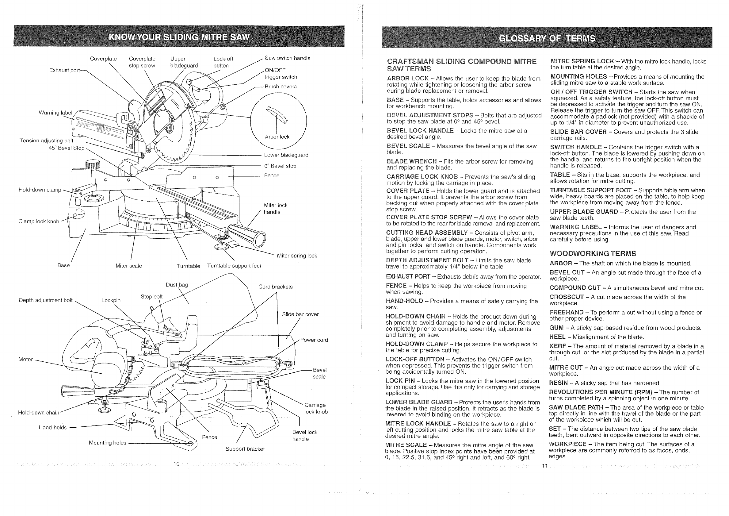
Exhaust
Coverplate Coverplate
stopscrew Upper
btadeguard Lock-off
button Sawswitchhandle
ON/OFF
triggerswitch
Brushcovers
Warning label
Tension adjusting bolt
45° Bevel Stop .,..
Hold-down champ
Clamp hock
o o
Arborlock
Lower bladeguard
0° Bevel slop
Fence
Miter lock
handle
Base
I
Miter scale Turntable Turntable support foot
Miter Spring lock
Depth adjustment bolt Lockpin Stop bolt
Dust\Cord brackets
Slide bar cover
Motor
Bevel
scale
Hold-down cha
Hand-holds
Mounting holes
Fence
Support bracket
Carriage
lock knob
Bevel lock
handle
CRAFTSMAN SUDING COMPOUND MITRE
SAW TERMS
ARBOR LOCK -Allows the user to keep the blade from
rotating while tightening or loosening the arbor screw
during blade replacement or removal.
BASE - Supports the table, holds accessories and allows
for workbench mounting.
BEVEL ADJUSTMENT STOPS - Bolts that are adjusted
to stop the saw blade at 0° and 45° bevel.
BEVEL LOCK HANDLE - Locks the mitre saw at a
desired bevel angle.
BEVEL SCALE - Measures the bevel angle of the saw
blade.
BLADE WRENCH - Fits the arbor screw for removing
and replacing the blade.
CARRBAGE LOCK KNOB - Prevents the saw's sliding
motion by locking the carriage in place.
COVER PLATE - Holds the lower guard and is attached
to the upper guard, it prevents the arbor screw from
backing out when properly attached with the cover plate
stop screw.
COVER PLATE STOP SCREW -Allows the cover plate
to be rotated to the rear for blade removal and replacement.
CUTTING HEAD ASSEMBLY -Consists of pivot arm,
blade, upper and lower blade guards, motor, switch, arbor
and pin locks, and switch on handle. Components work
together to perform cutting operation.
DEPTH ADJUSTMENT BOLT - Limits the saw blade
travel to approximately i/4" below the table,
EXHAUST PORT - Exhausts debris away from the operator.
FENCE - Helps to keep the workpiece from moving
when sawing.
HAND-HOLD - Provides a means of safely carrying the
saw,
HOLD-DOWN CHAIN - Holds the product down during
shipment to avoid damage to handle and motor. Remove
completely prior to completing assembly, adjustments
and turning on saw.
HOLD-DOWN CLAMP - Helps secure the workpiece to
the table for precise cutting.
LOCK-OFF BUTTON -Activates the ON/OFF switch
when depressed. This prevents the trigger switch from
being accidentally turned ON.
LOCK P_N - Locks the mitre saw in the lowered position
for compact storage. Use this only for carrying and storage
applications.
LOWER BLADE GUARD - Protects the user's hands from
the blade in the raised position. It retracts as the blade is
lowered to avoid binding on the workpiece.
M_TRE LOCK HANDLE - Rotates the saw to a right or
left cutting position and locks the mitre saw table at the
desired mitre angle.
MITRE SCALE - Measures the mitre angle of the saw
blade. Positive stop index points have been provided at
0, !5, 22.5, 31.6, and 450 right and left, and 600 right.
.... 11
IVttTRE SPRING LOCK-With the mitre lock handle, locks
the turn table at the desired angle.
MOUNTING HOLES - Provides a means of mounting the
sliding mitre saw to a stable work surface.
ON !OFF TRIGGER SWITCH - Starts the saw when
squeezed. As a safety feature, the Iock-off button must
be depressed to activate the trigger and turn the saw ON.
Release the trigger to turn the saw OFE This switch can
accommodate a padlock (not provided) with a shackle of
up to 1/4" in diameter to prevent unauthorized use.
SLIDE BAR COVER - Covers and protects the 3 slide
carriage rails.
SWITCH HANDLE - Contains the trigger switch with a
lock-off button. The blade is lowered by pushing down on
the handle, and returns to the upright position when the
handle is released.
TABLE -- Sits in the base, supports the workpiece, and
allows rotation for mitre cutting.
TURNTABLE SUPPORT FOOT - Supports table arm when
wide, heavy boards are placed on the table, to help keep
the workpiece from moving away from the fence.
UPPER BLADE GUARD - Protects the user from the
saw blade teeth.
WARNING LABEL -Informs the user of dangers and
necessary precautions in the use of this saw. Read
carefully before using.
WOODWORKUNG TERMS
ARBOR -The shaft on which the blade is mounted.
BEVEL CUT -An angle cut made through the face of a
workpiece.
COMPOUND CUT -A simultaneous bevel and mitre cut.
CROSSCUT - A cut made across the width of the
workpiece.
FREEHAND -To perform a cut without using a fence or
other proper device.
GUM -A sticky sap-based residue from wood products.
HEEL - Misalignment of the blade.
KERF -The amount of material removed by a blade in a
through cut, or the slot produced by the blade in a partial
cut.
MITRE CUT - An angle cut made across the width of a
workpiece.
RESIN -A sticky sap that has hardened.
REVOLUTIONS PER MINUTE (RPM) - The number of
turns completed by a spinning object in one minute.
SAW BLADE PATH - The area of the workpiece or table
top directly in line with the travel of the blade or the part
of the workpiece which will be cut.
SET - The distance between two tips of the saw blade
teeth, bent outward in opposite directions to each other.
WORKPIECE -The item being cut. The surfaces of a
workpiece are commonly referred to as faces, ends,
edges.

ASSEMBLY INSTRUCTIONS
TOOLS NEEDED
Tools required for adjustments:
Adjustable wrench
t
Combination square
Hex blade wrench (supplied)
Phillips screwdriver
For your safety, never connect plug to power source
receptacle until all assembly and adjustment steps are
completed, and you have read and understood the safety
and operating instructions.
To avoid injury, saw misalignment, and electrical problems
when moving tool from one location to another location
lock the carriage lock knob and lift saw by the carry
handle, or by the hand-hold openings on both ends of
the base, using both hands.
INSTALLING THE TURNTABLE SUPPORT FOOT (FIG. A)
1. Locate the adjusting nut (1) and turntable support
foot (2).
2. Carefully thread the adjusting nut onto support foot
and screw the assembly into the hole under the
control arm (3) of the turntable (4).
Fig. A
3
2
i/_:,':::i!L?L:: ;-:::: :-:: ::_ii/ii::_i:;:/:i::i:/::¢ ;LI: ::ii:: ::: ::i:::/:::/i/: !,_::i::: ? ::i__::!¸
[NSTALUNG THE MITRE LOCK HANDLE (FroG.A)
1. Carefully screw the mitre lock handle (5) clockwise
into hole of the control arm (3) located at the front of
the turntable, and tighten.
2. To unlock the turntable from its set position, loosen
the mitre lock handle by turning 1/4 turn or more
counterclockwise. Squeeze the mitre spring lock
lever (6), move the control arm (3), and set the
indicator (7) to 0°.
3. To lock, tighten mitre lock handle (5) by turning
clockwise.
iNSTALLING THE HOLD-DOWN CLAMP ASSEMBLY
TO SAW (RG. B and C)
A hold-down clamp assembly is commonly used on the
left side of the saw base to support the workpiece. The
assembly location is determined by the thickness and
width of the workpiece. A clamp is usually positioned or,
the table for narrow and thin woodstock and in the mounting
hole on the left side of the fence for thicker and wider
boards.
NOTE: An additional hold-down clamp accessory may be
purchased to secure the workpiece on the right side for
long pieces of wood. This reduces the possibility of the
workpiece lifting near the blade during a cutting operation.
Hold-down clamp on table (FIG. B)
1. Tighten the lock knob bolt (2) and screw the lock
knob bolt partially into the hole in the front side of
the saw base (3)_
2. Insert the rod of the hold-down clamp assembly (4)
into the hole on the top of the saw base, and tighten
the lock knob bolt securely.
3. Tighten the hex nut securely against the saw base.
Fig. B
O
12 : ....
Hold-down clamp on fence (FIG. C)
t. Position the hex nut (1) into the rectangular hole on
the backside of the fence (2).
2. Insert the lock knob bolt (3) through the slotted hole
and thread i1_through the hex nut, as shown.
3. Insert the rod of the hold-down clamp assembly (4)
into the round hole and tighten the lock knob bolt (3).
4. These lock knob bolts and hex nuts can be screwed
into the fence post hole or stored for later use.
Fig. C
SAW BLADE WRENCH (FIG. D)
Store the blade wrench (1) by sliding the small end of the
wrench into the saw housing slot (2), and position behind
the storage clip (3) to prevent loss.
3
1
_NSTALLtNGTHE DUST BAG (FIG. E)
1. To install the dust bag (t), squeeze the metal collar
wings (2).
2. Place the dust bag neck opening around the exhaust
port (3), and release the metal collar wings.
1 2
Fig. 3
REMOVING OR INSTALLING THE BLADE (FIG. F, G, H)
To avoid injury, only use blades recommended for this
saw, with the proper diameter of 8 1/2 inches and
designed for blade speeds not less than 5000 RPM.
To avoid injury from an accidental start, make sure the
switch is in the OFF position and the plug is not
connected to the power source receptacle.
CAUTION: To avoid cuts from extremely sharp teeth on
blades, wear gloves when installing or removing blades.
Removing blade
1. Unplug the saw from the power source receptacle.
2. Allow the cutting head assembly (1) to rise to the
upright position by pulling the lock pin (2), outward.
(FIG. F) _,
Fig. F
I\
3. Loosen the cover plate screw (3) with a screwdriver.
4. Rotate the cover plate (4), upward to expose the
arbor screw nut (5).
5. Place the hex end of the blade wrench (6) (provided)
over the arbor screw (5).
6. Locate the arbor lock (7) between the upper blade
guard (8) and the mitre saw switch handle (9). (FIG, G)
Fig. G 43
5
6
13 ; :

7,
,
Press the arbor lock (7), holding it in firmly while
turning the blade wrench clockwise. The arbor lock
will engage after turning the wrench. Continue to
hold the arbor lock in to keep it engaged, while turning
the wrench clockwise to loosen the arbor screw (5).
NOTE: The arbor lock can be damaged by improper
use. If the arbor lock wilt not hold, lower the blade
down on to a scrap of wood positioned against the
fence. This will serve as an alternative locking method.
Raise the lower blade guard. Remove the arbor
screw (5), arbor washer (10), outer blade collar (1t).
and remove the blade (12). Do not remove tile inner
blade collar. (FIG. H)
NOTE: Pay attention to the pieces removed, noting
their position and direction they face. Wipe the blade
collars clean of any sawdust before installing the new
blades.
/
5t0 11
12
Installing blades (FIG. F, G, H)
1. Raise the lower blade guard.
2. Install the 8 1/2" blade (12), making sure the rotation
arrow on the blade matches the clockwise rotation
arrow on the upper blade guard.
3. Place the arbor washer (10) on the arbor screw (5).
Install the outer blade collar (11), the arbor washer,
and arbor screw.
CAUTION: Make sure the recessed side of the blade
collar is facing the blade.
4. Place the blade wrench on the arbor screw.
5. Press the arbor lock (7), holding it in firmly while
turning the blade wrench counterclockwise. When it
engages continue to press the arbor lock in, while
tightening the arbor screw securely.
6. Rotate the cover plate (4) back until the slot in the
cover plate engages with the cover plate screw (3).
Tighten the screw with a screwdriver.
7. Be sure the arbor lock is released so the blade turns
freely.
To avoid serious injury or death, do not use the saw without
the cover plate securely in place. It keeps the arbor screw
from falling out if it accidentally loosens, and helps prevent
the spinning blade from coming off the saw.
To avoid injury, make sure the collars are ciean and
properly arranged. After installing a new blade, make
sure the blade clears the table slot at the 0° and 45°
bevel positions. Lower the blade into the table and check
for any contact with the metal base or the turntable.
REMOVING AND _NSTALLING TABLE INSERT (FIG. _)
To avoid injury, do not start the sliding compound mitre
saw without checking for interference between [he blade
and table insert. Damage could result to the blade, table
insert or turntable if blade strike occurs during the cutting
operation.
To avoid injury from materials being thrown, always
unplug saw to avoid accidental starting and remove small
pieces of material from the table control arm cavity. The
table insert may be removed for this purpose, but always
reattach table insert prior to performing a cutting
operation.
1. To remove, loosen and remove the six screws (1) on
the table insert (2) with a screwdriver and lift the
insert.
2. To install, reposition the table insert, install the six
screws and tighten.
3. Check for blade clearance by moving the carriage
through the fulf motion of the blade in the slot.
2.
To avoid possible personal injury or damage to the miter
saw due to tipping, do not operate the saw without the
support bracket securely in position. 3.
INSTALLING THE ANTI-TIP SUPPORT (F_G. K}
1. Insert each foot of the anti-tip support in the holes on
the rear of the base.
2. Tighten the anti-tip support with two screws supplied.
Fig. K
i
i
I
I
While holding the lock handle (t), lift and squeeze
the mitre spring tock (3). Move the turntable control
arm to the desired position.
To lock the turntable into position, release the mitre
spring lock (3), and turn the mitre lock handle (1)
clockwise until tight.
NOTE: The control arm should be supported, using
the turntable support foot, for the safest and most
accurate cuts of thicker and wider boards.
4. Turn the support foot (4) clockwise until the foot
seats against the surface of the bench.
5. Tighten the adjusting nut (5) counterclockwise and
lock the support foot securely.
Fig. L
ADJUSTMENTS INST,RUCTMONS
To avoid injury from an accidental start, make sure the
switch is in the OFF position and the plug is not
connected to the power source receptacle.
CONTROL ARM OR MITRE ADJUSTMENT (FIG. L)
The sliding compound mitre saw scale can be easily
read showing mitre angles from 0 to 450 to the left and
right, and 0 to 60 ° to the right, The most common angle
cut setting slots have positive stops, permitting fast
adjustments to the desired position. Follow the process
below for quickest and most accurate adjustments:
1 Release the turntable mitre lock handle (t) at the
front of the control arm (2) by turning the knob
counterclockwise 1/4 turn.
ADJUSTMENT OF MITRE SCALE INDICATOR (FIG, M)
I. Move the control arm to the positive stop perpendicular
to the saw base.
2. Loosen the screw (t) that holds the indicator with a
screwdriver,
3. Adjust the indicator (2) to the 0Qmark and retighten
screw.
Fig. M
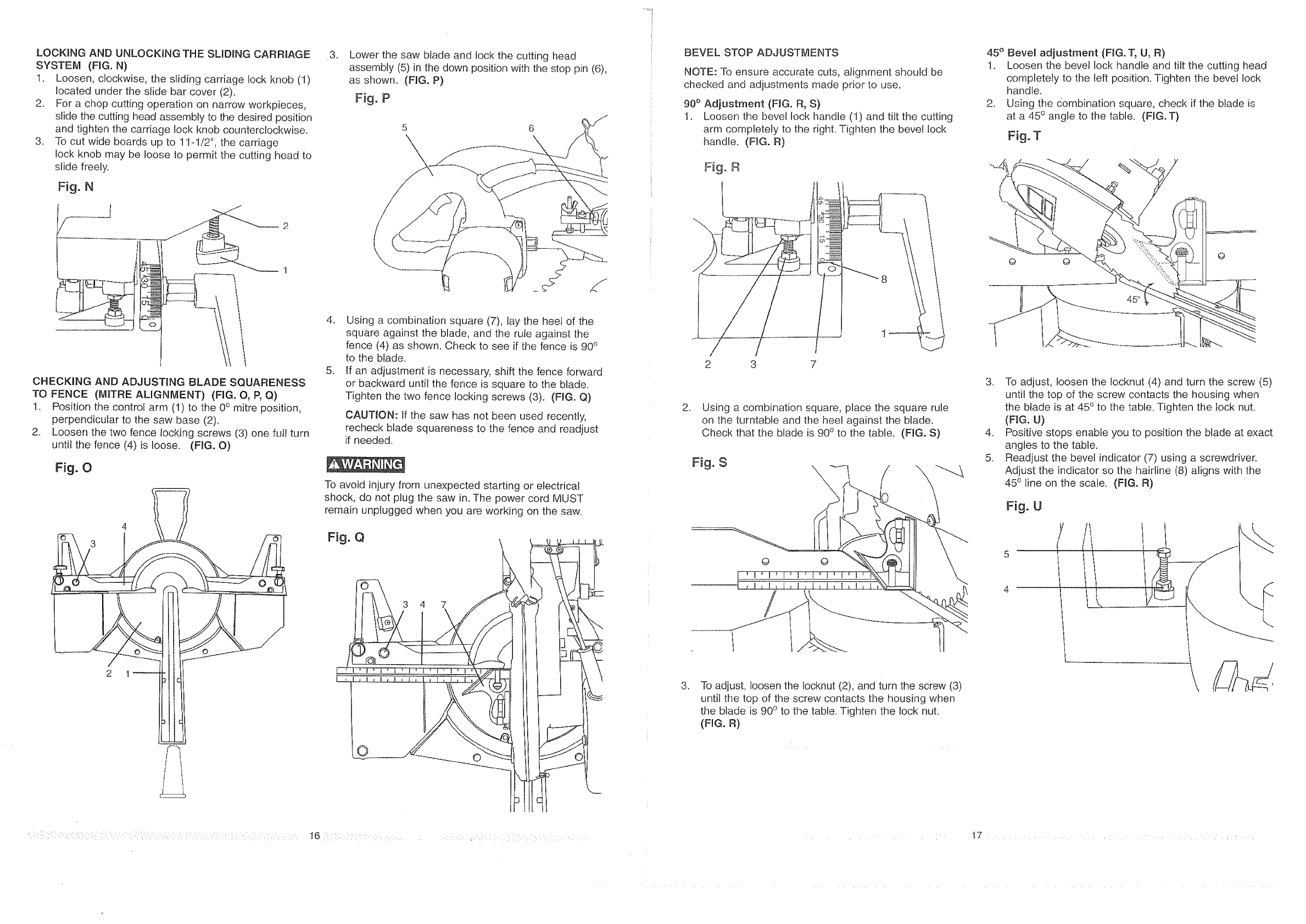
LOCKING AND UNLOCKING THE SLIDING CARRIAGE
SYSTEM (FIG, N)
1, Loosen, clockwise, the sliding carriage lock knob (1)
located under the slide bar cover (2),
2. For a chop cutting operation on narrow workpieces,
slide the cutting head assembly to the desired position
and tighten the carriage lock knob counterclockwise,
3, To cut wide boards up to 1t-1/2", the carriage
lock knob may be loose 1o permit the cutting head to
slide freely.
Fig. N
CHECKING AND ADJUSTING BLADE SQUARENESS
TO FENCE (MITRE ALIGNMENT) (FIG. O, P, Q)
1. Position the control arm (1) to the 0° mitre position,
perpendicular to the saw base (2).
2, Loosen the two fence locking screws (3) one ful! turn
until the fence (4) is loose, (FIG. O)
Fig, O
4
3
3, Lower the saw blade and lock the cutting head
assembly (5) in the down position with the stop pin (6),
as shown. (FIG. P)
Fig, P
4. Using a combination square (7), lay the heel of the
square against the blade, and the rule against the
fence (4) as shown. Check to see if the fence is 90°
to the blade.
5. If an adjustment is necessary, shift the fence forward
or backward until the fence is square to the blade.
Tighten the two fence locking screws (3). (FIG. Q)
CAUTION: If the saw has not been used recently,
recheck blade squareness to the fence and readjust
if needed.
To avoid injury from unexpected starting or electrical
shock, do not plug the saw in. The power cord MUST
remain unplugged when you are working on the saw.
Fig, Q
3 4 7
BEVEL STOP ADJUSTMENTS
NOTE: To ensure accurate cuts, alignment should be
checked and adjustments made prior to use.
90 ° Adjustment (FIG. R, S)
t. Loosen the bevel lock handle (1) and tilt the cutting
arm completely to the righL Tighten the bevel lock
handle. (FIG. R)
Fig. R
G3 ----
2 3 7
2. Using a combination square, place the square rule
on the turntable and the heel against the blade.
Check that the blade is 90° to the [able. (FIG. S)
Fig, S
© ©
"---4
,To adjust, loosen the Iocknut (2), and turn the screw (3)
until the top of the screw contacts the housing when
the blade is 90° to the table. Tighten the lock nut.
(FIG, R)
45° Bevel adjustment (F_G.T, U, R)
1. Loosen the bevel lock handle and tilt the cutting head
completely to the left position. Tighten the bevel lock
handle.
2. Using the combination square, check if the blade is
at a 45° angle to the table. (FIG. T)
Fig. T
O O
3. To adjust, loosen the !ocknut (4) and turn the screw (5)
until the top of the screw contacts the housing when
the blade is at 450 to the table. Tighten the lock nut.
(FIG. U)
4. Positive stops enable you to position the blade at exact
angles to the table.
5. Readjust the bevel indicator (7) using a screwdriver.
Adjust the indicator so the hairline (8) aligns with the
450 line on the scale. (FIG. R)
Fig. U
/
4
::::!i_:::i!.: ¸z¸:::/:::':/::/_ : ::::::::/::::::: ::i::::: !::::::i ?:!:::i:!: :::< t6 ::::::::::::_h.: /::.
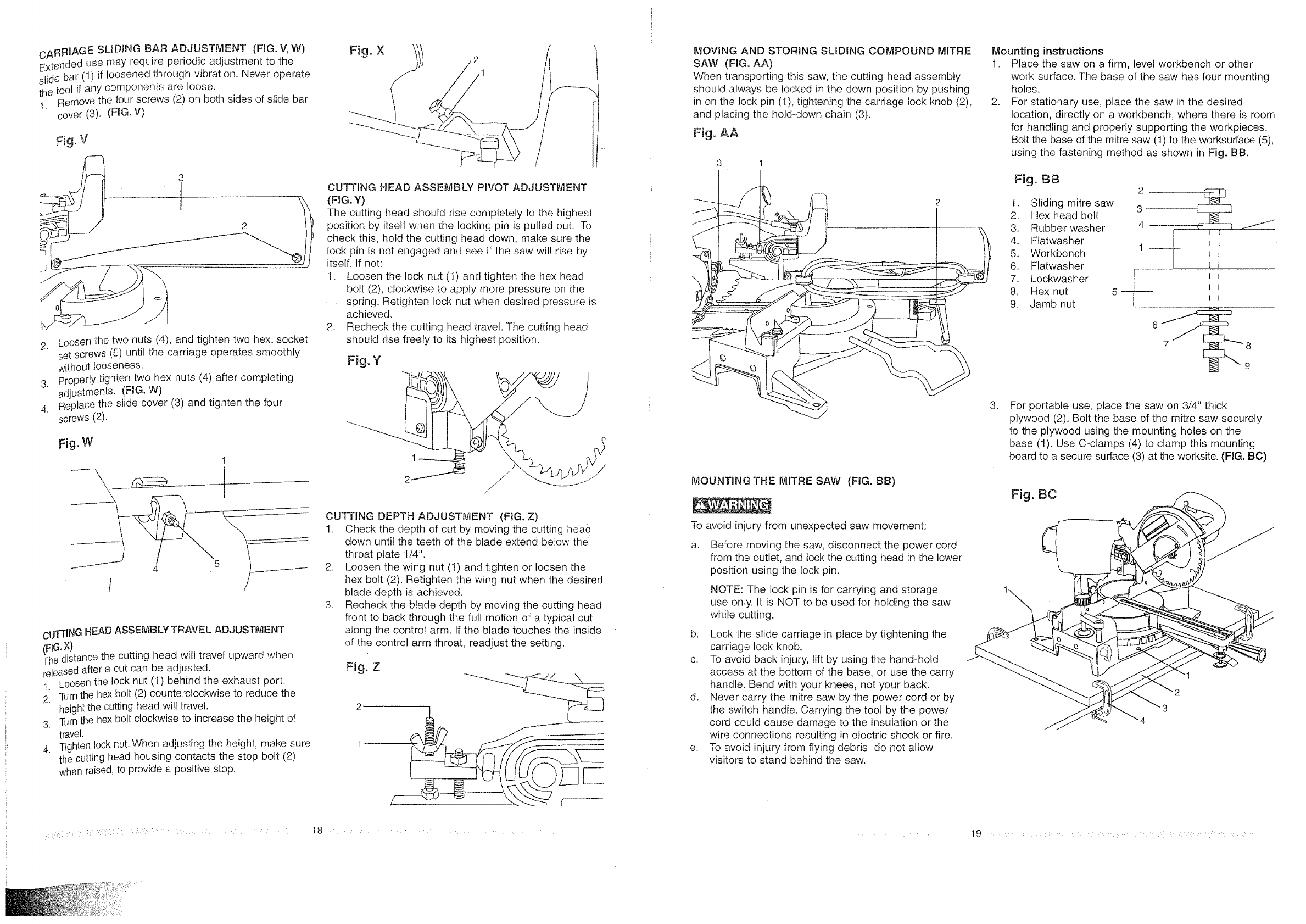
CARRIAGE SMDING BAR ADJUSTMENT (FIG. V, W)
Extended use may require periodic adjustment to the
slide bar (1) if loosened through vibration. Never operate
the tool if any components are loose.
1. Remove the four screws (2) on both sides of slide bar
cover (3). (FIG.V}
3
t
1
2. Loosen the two nuts (4), and tighten two hex. socket
set screws (5) until the carriage operates smoothly
without looseness.
3. Properly tighten two hex nuts (4) after completing
adjustments. (FIG. W)
4. Replace the slide cover (3) and tighten the four
screws (2).
Fig, W
1
CUTTINGHEAD ASSEMBLYTRAVEL ADJUSTMENT
(FIG.X)
The distance the cutting head will travel upward when
releasedafter a cut can be adjusted.
t. Loosen the lock nut (t) behind the exhaust port.
2. Turnthe hex bolt (2) counterclockwise to reduce the
heightthe cutting head wilt travel.
3. Turnthe hex bolt clockwise to increase the height of
travel.
4. Tightenlock nut. When adjusting the height, make sure
the cutting head housing contacts the stop bolt (2)
when raised,to provide a positive stop.
Fig. X
CUTTING HEAD ASSEMBLY PIVOT ADJUSTMENT
(FIG. Y)
The cutting head should rise completely to the highest
position by itself when the locking pin is pulled out. To
check this, hold the cutting head down, make sure the
lock pin is not engaged and see if the saw wil! rise by
itself. If not:
1. Loosen the lock nut (1) and tighten the hex head
bolt (2), clockwise to apply more pressure on the
spring. Retighten lock nut when desired pressure is
achieved.
2. Recheck the cutting head travel. The cutting head
should rise freely to its highest position.
Fig. Y
1
2
CUTTING DEPTH ADJUSTMENT (FIG. Z)
1. Check the depth of cut by moving the cutting head
down until the teeth of the blade extend befow the
throat plate 1/4".
2. Loosen the wing nut (t) and tighten or loosen the
hex bolt (2). Retighten the wing nut when the desired
blade depth is achieved.
3. Recheck the blade depth by moving the cutting head
front to back through the full motion of a typical cut
a}ong the control arm. If the blade touches the inside
of the control arm throat, readjust the setting.
Fig. Z
2 ................................
1
MOVING AND STORING SLIDING COMPOUND MITRE
SAW (FIG. AA)
When transporting this saw, the cutting head assembIy
should always be locked in the down position by pushing
in on the lock pin (I), tightening the carriage lock knob (2),
and placing the hold-down chain (3).
Fig. AA
3 1
MOUNTING THE MITRE SAW (FIG. BB)
To avoid injury from unexpected saw movement:
a. Before moving the saw, disconnect the power cord
from the outlet, and lock the cutting head in the lower
position using the lock pin.
NOTE: The lock pin is for carrying and storage
use only. It is NOT to be used for holding the saw
while cutting.
b. Lock the slide carriage in place by tightening the
carriage lock knob.
c. To avoid back injury, lift by using the hand-hold
access at the bottom of the base, or use the carry
handle. Bend with your knees, not your back.
d. Never carry the mitre saw by the power cord or by
the switch handle. Carrying the too! by the power
cord could cause damage to the insulation or the
wire connections resulting in electric shock or fire.
e. To avoid injury from flying debris, do not allow
visitors to stand behind the saw.
Mounting instructions
1. Place the saw on a firm, level workbench or other
work surface. The base of the saw has four mounting
holes.
2. For stationary use, place the saw in the desired
location, directly on a workbench, where there is room
for handling and properly supporting the workpieces.
Bolt the base of the mitre saw (1) to the worksurface (5),
using the fastening method as shown in Fig. BB.
Fig. BB
1. Sliding mitre saw
2. Hex head bolt
3. Rubber washer
4. Flatwasher
5. Workbench
6. Flatwasher
7. Lockwasher
8. Hex nut
9. Jamb nut
2
3
4I E
i
5 i
I
.For portable use, place the saw on 3/4" thick
plywood (2). Bolt the base of the mitre saw securely
to the plywood using the mounting holes on the
base (!). Use C-clamps (4) to clamp this mounting
board to a secure surface (3) at the worksite. (FIG. BC)
Fig. BC
3

Cut materials can be thrown and extensive exposure to
noise can cause hearing problems; always wear safety
glasses and proper hearing protection such as ear plugs
when performing cutting operations.
Don't allow familiarity, gained from frequent use of your
mitre saw, to result in a careless mistake. A careless
fraction of a second is enough to cause a severe injury.
Before cutting, if the saw makes an unfamiliar noise or
vibrates, stop immediately. Turn the saw OFF. Unplug the
saw. To avoid injury, do not restart until finding and
correcting the problem.
For your convenient use, your saw has a blade brake,
The brake is not a safety device. Never rely on it to
replace the proper use of the guard on your saw. To
prevent injury, if the blade does not stop within 6
seconds, unplug the saw and follow the instructions in
the TROUBLESHOOTING GUIDE for adjusting the brake
before continued use.
TO TURN SAW ON (FIG. CC)
Directly below and on the switch handle is the thumb
activated lock-off switch (!). It must be depressed to unlock
the trigger switch (2) and start the sliding compound
mitre saw.
1 2
Fig. CC
BODY AND HAND POSITIONS (RG. DD)
Fig, DD
\
\
\
6 1/2"
Proper positioning of your body and hands when operating
the mitre saw wilt make cutting easier and safer. Use a
hold-down clamp assembly, whenever possible. Never
place hands near the cutting area. Place hand at least
6-1/2" away from the path of the blade. Hold workpiece
firmly against the fence to prevent movement toward the
blade. Keep hands in position until the trigger has been
released and the blade has completely stopped. Stand in a
position so the body is to the left side of the blade but
never stand directly behind the blade when performing a
cutting operation. Before making a cut, make a "dry run"
with the power off so you can see the path of the blade.
Keep children away. Keep all visitors a safe distance
from the mitre saw. Make sure bystanders are clear of the
mitre saw and workpiece.
Don't force tool. It will do the job better and safer at its
designed rate. Feed the saw into the workpiece slowly
with a firm downward motion .....
Before freeing jammed material:
a. Turn switch ©FR
b. Unplug the mitre saw.
c. Wait for all moving parts to stop.
:' 20 ::',';::::, : : .......
After finishing a cut:
a. Keep holding the cutting head down.
b. Release the switch, and wait for all moving parts
to stop before moving your hands.
c. Ifthe blade doesn't stop within 6 seconds,
unplug the saw and follow the instructions in the
TROUBLESHOOTmNG GUIDE for adjusting the
blade brake before using the saw again.
BEFORE LEAVING THE SAW
Never leave tool running unattended. Turn power OFR
Wait for all moving parts to stop and unplug the power
cord from outlet. Make workshop child-proof. Lock the
shop. Disconnect master switches. Store tool away from
children and other unqualified users.
To avoid possible personal injury or damage to the miter
saw due to tipping, do not operate the saw without the
support bracket securely in position.
BASIC SAW OPERATmONS
MITRE CUT (FIG. EE)
The sliding compound mitre saw is equipped with
positive mitre stops on the saw base below the scale and
control arm of turntable. The !ocations are at 0, 15, 22.5,
31.6 and 45 degrees left and 15, 22.5, 31.6, 45, and 60
degrees to the right. These locations represent the most
common angles for cutting operations.
1. When a mitre cut is required, move the cutting head
assembly to the desired mitre angle by turning the
mitre lock handle (1) counterclockwise. This unlocks
the mitre spring lock and table. Lift up and hold the
mitre spring lock handle (2).
2. Using the mitre lock handle, holding the spring
lock handle up, rotate the turntable (3) to the desired
mitre ang]e on the scale, right or left. When the
table is in the desired position, release the mitre
spring lock (2) and tighten the mitre !ock handle (1).
The table is now locked at the desired angle.
Fig. EE
/
3,''"A"',_ 2
/
Move feet with miter angle
NNNNIN
To avoid injury from materials being thrown, unplug saw
to avoid accidental starting; and then remove small
materials from the control arm cavity prior to the next
cutting operation. The table insert may be removed for
this purpose, but always reattach table insert prior to
performing a cutting operation.
CHOP CUTTING NARROW BOARDS- 90° CROSSCUT
(RG. FF)
1, Slide the carriage (1) to the rear position as far as it
will go.
2. Lock the carriage lock knob (2).
3, Lock turntable lock knob (3) on fence.
4, Position the cutting head to the 0° bevel position, and
lock the bevel lock handle.
5, Position the control arm (4) to the 0° mitre angle and
lock the mitre lock handle. (Refer to mitre cut operation),
6. Position the workpiece on the table and against the
fence. Use a hold-down clamp (5) attached to the
base or fence, whenever possible.
7. Press the lock (6) on side of handle and pull the
trigger (7), turning on the saw. Lower the blade by
pushing the handle (8) down into the workpiece with
slow and even pressure.
8. When the cut is complete, release the switch and
allow the blade to stop before raising the cutting
head assembly.-
Fig. FF
6
21 :: :
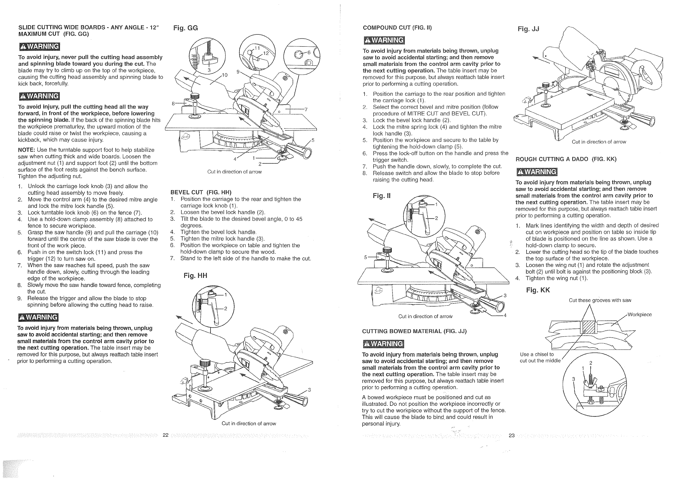
SLIDECUTTINGWIDEBOARDS- ANYANGLE- 12"
MAXIMUMCUT(FIG.GG)
Toavoidinjury,neverpull thecutting headassembly
andspinningbladetowardyouduringthecut.The
blademaytrytoclimbuponthetopoftheworkpiece,
causingthecuttingheadassemblyandspinningbladeto
kickback,forcefully.
Toavoidinjury, pull the cutting head all the way
forward, in front of the workpiece, before lowering
the spinning blade. If the back of the spinning blade hits
the workpiece prematurley, the upward motion of the
blade could raise or twist the workpiece, causing a
kickback, which may cause injury.
NOTE: Use the turntable support foot to help stabilize
saw when cutting thick and wide boards. Loosen the
adjustment nut (t) and support foot (2) until the bottom
surface of the foot rests against the bench surface.
Tighten the adjusting nut.
1. Unlock the carriage lock knob (3) and allow the
cutting head assembly to move freely.
2. Move the control arm (4) to the desired mitre angle
and lock the mitre lock handle (5).
3. Lock turntable lock knob (6) on the fence (7).
4. Use a hold-down clamp assembly (8) attached to
fence to secure workpiece.
5. Grasp the saw handle (9) and pull the carriage (10)
forward until the centre of the saw blade is over the
front of the work piece.
6. Push in on the switch lock (11) and press the
trigger (12) to turn saw on.
7. When the saw reaches full speed, push the saw
handle down, slowly, cutting through the leading
edge of the workpiece.
8. Slowly move the saw handle toward fence, completing
the cut.
9. Release the trigger and allow the blade to stop
spinning before allowing the cutting head to raise.
To avoid injury from materials being thrown, unplug
saw to avoid accidental starting; and then remove
small materials from the contrO! arm cavity prior to
the next cutting operation. The table insert may be
removed for this purpose, but always reattach table insert
prior to performing a cutting operation.
Fig. GG
4 lm 2
Cut in direction of arrow
BEVEL CUT (FIG. HH)
I. Position the carriage to the rear and tighten the
carriage lock knob (1).
2. Loosen the bevel lock handte (2).
3. Titt the blade to the desired bevel angle, 0 to 45
degrees.
4. Tighten the bevel lock handle.
5. Tighten the mitre lock handle (3).
6. Position the workpiece on table and tighten the
hold-down clamp to secure the wood.
7. Stand to the left side of the handle to make the cut.
Fig. HH
Cut in direction of arrow
22 : ......
COMPOUND CUT (RG. ml)
To avoid injury from materials being thrown, unplug
saw to avoid accidental starting; and then remove
small materials from the control arm cavity prior to
the next cutting operation. The table insert may be
removed for this purpose, but always reattach table insert
prior to performing a cutting operation.
t. Position the carriage to the rear position and tighten
the carriage lock (t).
2, Select the correct bevel and mitre position (follow
procedure of MITRE CUT and BEVEL CUT).
3. Lock the bevel lock handle (2).
4. Lock the mitre spring lock (4) and tighten the mitre
lock handle (3).
5. Position the workpiece and secure to the table by
tightening the hold-down clamp (5).
6. Press the lock-off button on the handle and press the
trigger switch.
7. Push the handle down, slowly, to complete the cut.
8. Release switch and allow the blade to stop before
raising the cutting head.
\
Out in direction of arrow
CUTTING BOWED MATER_AL (FIG. JJ)
To avoid injury from materials being thrown, unplug
saw to avoid accidental starting; and then remove
smalt materials from the control arm cavity prior to
the next cutting operation. The table insert may be
removed for this purpose, but always reattach table insert
prior to performing a cutting operation.
A bowed workpiece must be positioned and cut as
illustrated. Do not position the workpiece incorrectly or
try to cut the workpiece without the support of the fence.
This will cause the blade to bind and could result in
personal injury.
:: i_, :::!.i :
Fig. JJ
Cut in direction of arrow
ROUGH CUTTING A DADO (FIG. KK)
To avoid injury from materiaJs being thrown, unplug
saw to avoid accidentaJ starting; and then remove
small materials from the control arm cavity prior to
the next cutting operation, The table insert may be
removed for this purpose, but always reattach table insert
prior to performing a cutting operation.
1. Mark lines identifying the width and depth of desired
cut on workpiece and position on table so inside tip
of blade is positioned on the line as shown. Use a
hold-down clamp to secure.
2. Lower the cutting head so the tip of the blade touches
the top surface of the workpiece.
3. Loosen the wing nut (1) and rotate the adjustment
bolt (2) until bolt is against the positioning block (3).
4. Tighten the wing nut (1).
Fig.KK
Cut these grooves with saw
rkpiece
Use a chisel to /
cut out the middle
23
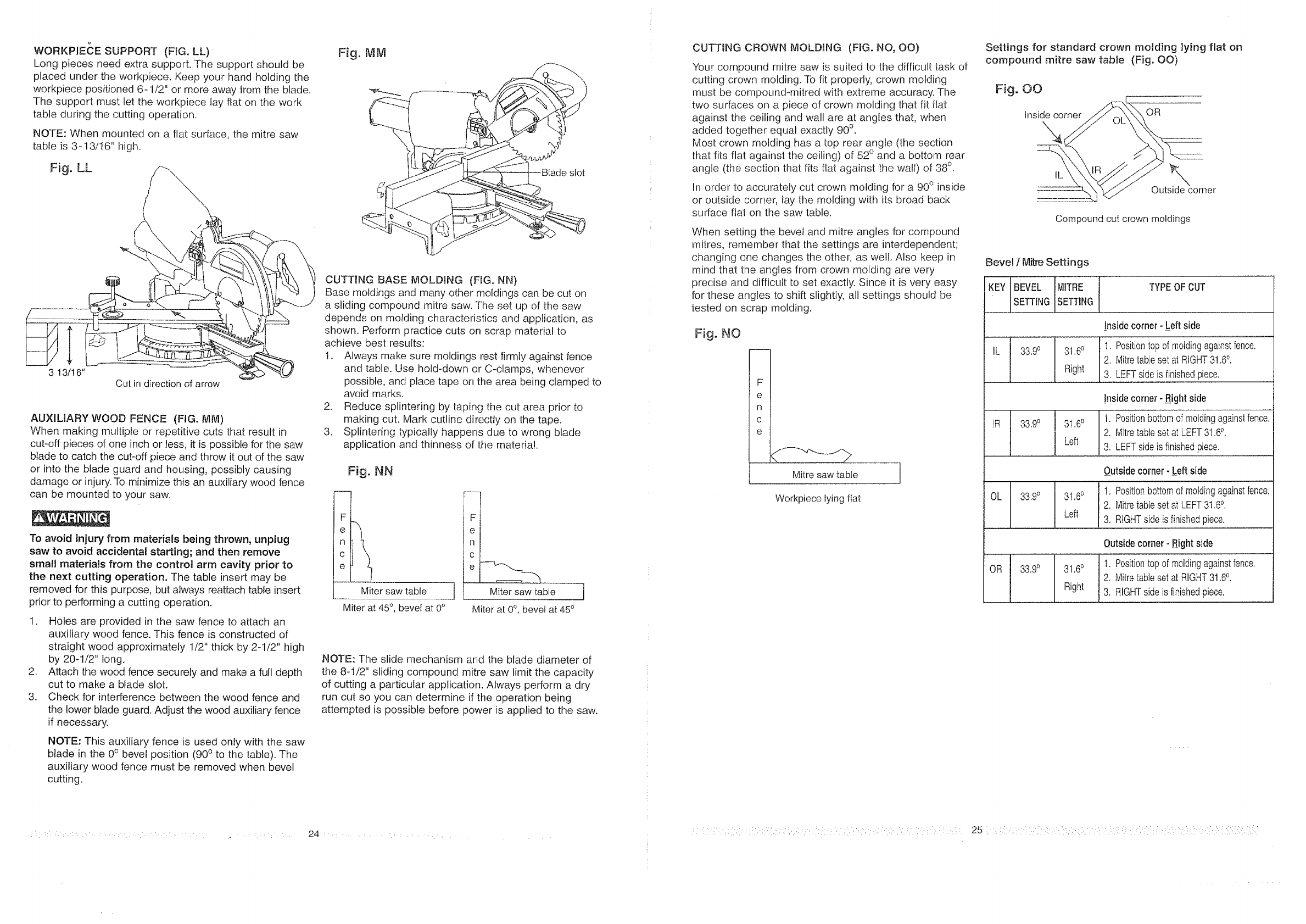
WORKPtECE SUPPORT (FIG. LL)
Long pieces need extra support. The support should be
placed under the workpiece, Keep your hand holding the
workpiece positioned 6-1/2" or more away from the blade.
The support must let the workpiece lay flat on the work
table during the cutting operation.
NOTE: When mounted on a flat surface, the mitre saw
table is 3-13/t6" high.
Fig. LL / ,"
3 13/16" Cut in direction of arrow
AUXILIARY WOOD FENCE (FlG. MM)
When making multiple or repetitive cuts that result in
cut-off pieces of one inch or less, it is possible for the saw
btade to catch the cut-off piece and throw it out of the saw
or into the blade guard and housing, possibly causing
damage or injury. To minimize this an auxiliary wood fence
can be mounted to your saw.
To avoid injury from materials being thrown, unplug
saw to avoid accidental starting; and then remove
small materials from the control arm cavity prior to
the next cutting operation. The table insert may be
removed for this purpose, but always reattach table insert
prior to performing a cutting operation.
1. Holes are provided in the saw fence to attach an
auxiliary wood fence. This fence is constructed of
straight wood approximately 1/2" thick by 2-1/2" high
by 20-1/2" long.
2. Attach the wood fence securely and make a full depth
cut to make a blade slot.
3. Check for interference between the wood fence and
the lower blade guard. Adjust the wood auxiliary fence
if necessary.
NOTE: This auxiliary fence is used only with the saw
blade in the 0° bevel position (900 to the table). The
auxiliary wood fence must be removed when bevel
cutting.
Fig. IViM
slot
CUTTRNG BASE MOLDING (FIG. NN)
Base moldings and many other moldings can be cut on
a sliding compound mitre saw. The set up of the saw
depends on molding characteristics and application, as
shown. Perform practice cuts on scrap material to
achieve best results:
1. Always make sure moldings rest firmly against fence
and table. Use hold-down or C-clamps, whenever
possible, and place tape on the area being clamped to
avoid marks.
2. Reduce splintering by taping the cut area prior to
making cut. Mark cutline directly on the tape.
3. Splintering typically happens due to wrong blade
application and thinness of the material.
Fig. NN
Ft
el
nl
c t
el-
Miter saw table
Miter at 45 °, bevel at 0°
F
Miter saw table
Miter at 0o, beve_at 450
]
NOTE: The slide mechanism and the blade diameter of
the 8-1/2" sliding compound mitre saw limit the capacity
of cutting a particular application. Always perform a dry
run cut so you can determine if the operation being
attempted is possible before power is applied to the saw.
CUTTING CROWN lVIOLDING (FIG, NO, OO)
Your compound mitre saw is suited to the difficult task of
cutting crown molding. To fit properly, crown molding
must be compoundomitred with extreme accuracy. The
two surfaces on a piece of crown molding that fit flat
against the ceiling and wall are at angles that, when
added together equal exactly 90° .
Most crown molding has a top rear angle (the section
that fits flat against the ceiling) of 52° and a bottom rear
angle (the section that fits flat against the walt) of 38°.
In order to accurately cut crown molding for a 90° inside
or outside corner, lay the molding with its broad back
surface ftat on the saw table.
When setting the bevel and mitre angles for compound
mitres, remember that the settings are interdependent;
changing one changes the other, as well. Also keep in
mind that the angles from crown molding are very
precise and difficult to set exactly. Since it is very easy
for these angles to shift slightly, all settings should be
tested on scrap molding.
Fig° NO
FI
e I
n i
c [
e t
Mitre sawtabfe
Workpiece lying flat
Settings for standard crown molding lying flat on
compound mitre saw tabte (Fig. 00)
Fig. OO
Inside corner
\, OR
IL \
Outside corner
Compound cut crown moldings
Bevel /Mice Settings
KEY BEVEL MITRE
SETTING SETTING
TYPE OF CUT
IL 33,90 31,6°
Right
Insidecorner. -Leftside
t, Positiontopof moldingagainstfence.
2. MitretabJesetat RIGHT31.6°.
3, LEFTsideisfinishedpiece.
IR 33.9° 3l .60
Left
0L 33.90
Insidecorner- _Rightside
1. P0'siti'on'bott0mof moldingagainstfenc'e'.'
2. MitretablesetatLEFT31.60.
3, LEFTsideis finishedpiece.
Outsidecorner- Left side
31.60 1. Positionbottomof moldingagainstfence.
2. MitretablesetatLEFT3t ,6°.
Left 3. RIGHTsideis finishedpiece.
Outsidecorner- Rightside
OR 33.9° 31.6° 1. Positiontopof moldingagainstfence.
2, Mitretablesetat RIGHT31.6°.
Right 3, RIGHTsideis finishedpiece.
25 1: : :
MAINTENANCE
DANGER
Never put lubricants on the blade while it is spinning.
To avoid fire or toxic reaction, never use gasoline,
naphtha, acetone, lacquer thinner or similar highly
volatile solvents to clean the sliding mitre saw.
To avoid injury from unexpected starting or electrical shock,
unplug the power cord before working on the saw.
For your safety, this saw is doubleqnsulated. To avoid
electrical shock, fire or injury, use only parts identical to
those identified in the parts list. Reassemble exactly as
the original assembly to avoid electrical shock.
REPLACING CARBON BRUSHES
The carbon brushes furnished wilI last approximately 50
hours of running time, or 10,000 ON /OFF cycles. Replace
both carbon brushes when either has less than 1/4" length
of carbon remaining. To inspect or replace brushes, first
unplug the saw, Then remove the black plastic cap on the
side of the motor (Remove the cap cautiously, because
it is springJoaded.) Then pull out the brush. Repeat for
the other side. To reassemble reverse the procedure. The
ears on -[he metal end of the assembly go in the same hole
the carbon part fits into. Tighten the cap snugly, but do
not overtighten.
NOTE: To reinstall the same brushes, first make sure the
brushes go back in the way they came out. This will avoid
a break-in period that reduces motor performance and
increases wear.
LOWER BLADE GUARD
Do not use the saw without the lower blade guard. The
lower blade guard is attached to the saw for your protection.
Should the lower guard become damaged, do not use
the saw until the damaged guard has been replaced.
Develop a regular check to make sure the lower guard is
working properly. Clean the Iower guard of any dust or
buildup with a damp cloth.
CAUTmON: Do not use solvents on the guard. They could
make the plastic "cloudy" and brittle.
When cleaning the lower guard, unplug the saw from the
power source receptacle to avoid unexpected startup.
SAWDUST
Periodically, sawdust will accumula[e under the work
table and base. This could cause difficulty in the
movement of the worktable when setting up a mitre cut.
Frequently blow out or vacuum up the sawdust.
If blowing sawdust, wear proper eye protection to keep
debris from blowing into eyes.
LUBRICANON
All the motor bearings in this tool are lubricated with a
sufficient amount of high grade lubricant for the life of the
unit under normal operating conditions; therefore, no
further lubrication is required (see below).
Infrequent lubrication as required:
Chop pivot: light machine oil or aerosol will penetrate
from the ends and junction points. A qualified service
technician can remove the pivot upstop to relieve
tension, and the 2 metric set screws holding the shaft, in
order to drive shaft about 3/4" right. Exposed surfaces
are lubricated with automotive type oil.
Central pivot of plastic guard: Use light household oil
(sewing machine oil) on metal-to-metal or metal-to-plastic
guard contact areas as required for smooth, quiet
operation. Avoid excessive oil, to which sawdust will
cling.
Bevel !ock handJe: Unscrew the handle assembly and
grease the threads.
Link: (which actuates the lower guard movement) may
be oiled at the rear pivot, greased at ball bearing contact,
and oiled where the link actuates the acetyt roller of the
lower guard, if the down chop motion is hard to start.
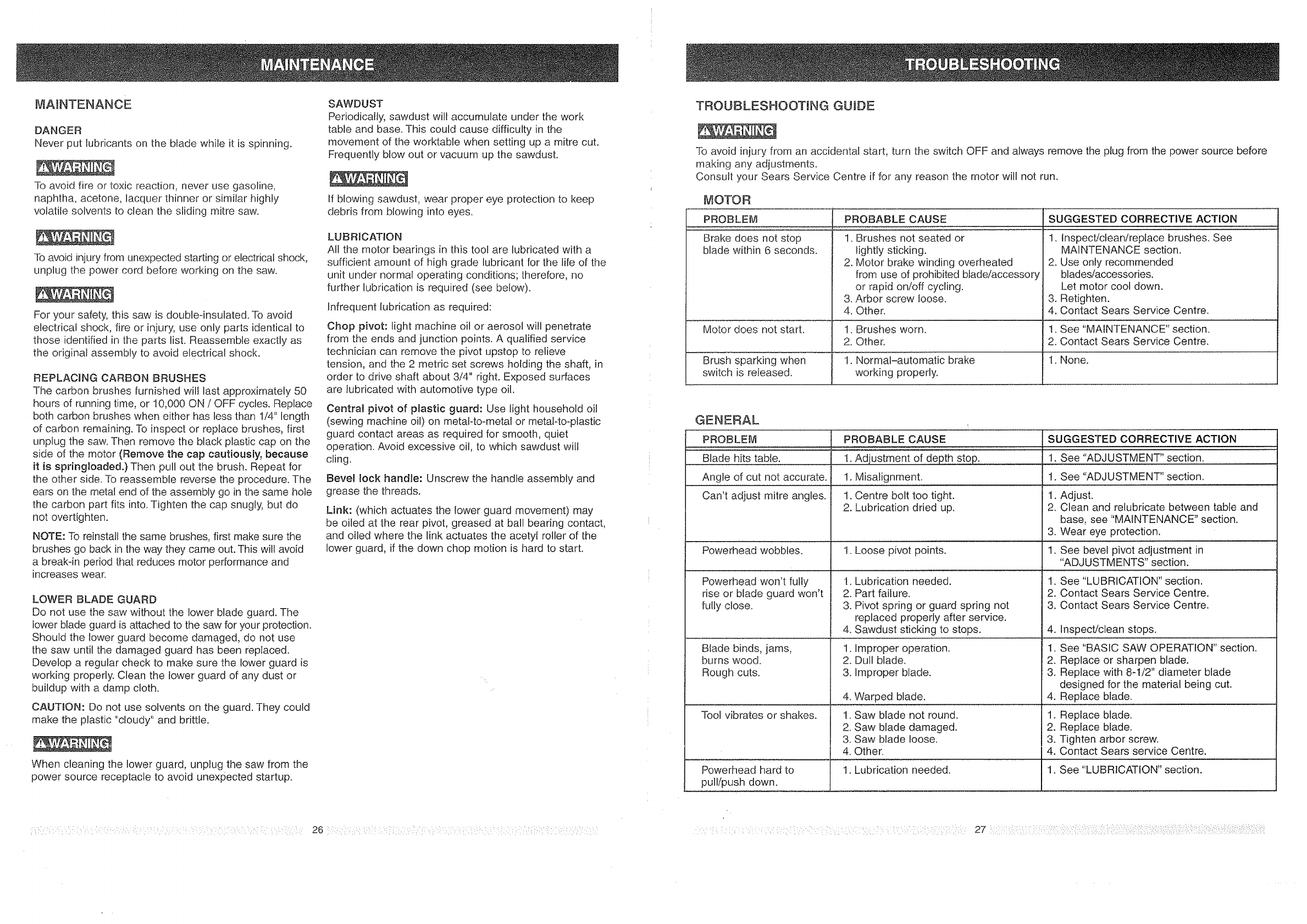
TROUBLESHOOTING GUIDE
To avoid injury from an accidental start, turn the switch OFF and always remove the plug from the power source before
making any adjustments.
Consult your Sears Service Centre if for any reason the motor will not run.
MOTOR
PROBLEM PROBABLE CAUSE
:: _ .:_ : f: f: :f : ..................
Brake does not stop 1. Brushes not seated or
blade within 6 seconds, lightly sticking.
2. Motor brake winding overheated
from use of prohibited blade/accessory
Motor does not start.
switch is released.
or rapid on/off cycling.
3. Arbor screw loose.
4. Other.
1. Brushes worn.
2. Other.
brake
working properly.
SUGGESTED CORRECTIVE ACTION
1. Inspect/clean/replace brushes. See
MAINTENANCE section.
2. Use only recommended
blades/accessories.
Let motor cool down.
3. Retighten.
4. Contact Sears Service Centre.
1. See "MAINTENANCE" section.
2. Contact Sears Service Centre.
I. None.
GENERAL
PROBLEM l PROBABLE CAUSE
Blade hiis {albie i i: '''''1.Adjustment 0[.dep..!.h....stop.
!
Angle of cut not accurate. I 1 Misalignment.
Can't adjust mitre angles. 1. Centre bolt too tight.
2. Lubrication dried up.
Powerhead wobbles, t. Loose pivot points.
Powerhead won't fully
rise or blade guard won't
fully close.
Blade binds, jams,
burns wood.
Rough cuts.
1. Lubrication needed. 1.
2. Part failure. 2.
3. Pivot spring or guard spring not 3.
replaced properly after service.
4. Sawdust sticking to stops. 4.
1. Improper operation. 1.
2. Dull blade. 2.
3. Improper blade. 3.
SUGGESTED CORRECTIVE ACTION
1. See '_ADJUSTMENT '' section.
1. See "ADJUSTMENT" section.
1. Adjust.
2, Clean and relubricate between table and
base, see "MAINTENANCE" section.
3. Wear eye protection,
1. See bevel pivot adjustment in
"ADJUSTMENTS" section.
See "LUBRICATION" section.
Contact Sears Service Centre.
Contact Sears Service Centre.
Inspect/clean stops.
See "BASIC SAW OPERATION" section.
Replace or sharpen blade.
Replace with 8-1/2" diameter blade
designed for the material being cut.
4. Warped blade. 4. Replace blade.
Tool vibrates or shakes, t. Saw blade not round. 1. Replace blade.
2. Saw blade damaged. 2. Replace blade.
3. Saw blade loose. 3. Tighten arbor screw.
4. Other. 4. Contact Sears service Centre.
1. Lubrication needed. 1. See "LUBRICATION" section.Powerhead hard to
pull/push down.
:::::::::::::::::::::::::::: 27 ::::::::::::::::::::::::::
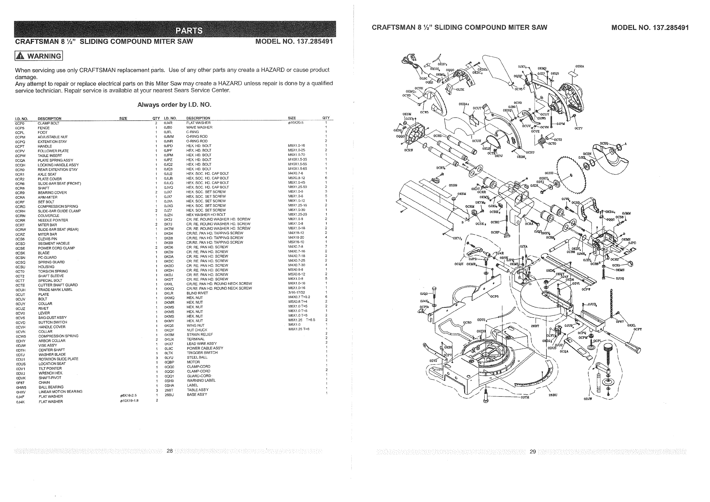
CRAFTSMAN 8 1/=,,SLIDING COMPOUND MITER SAW MODEL NO. t37.28549t
CRAFTSMAN 8 t/2" SLIDING COMPOUND MITER SAW MODEL NO. 137.285491
[A WARN,NG]
When servicing use only CRAFTSMAN replacement parts. Use of any other paris any create a HAZARD or cause product
damage.
Any attempt to repair or replace electrical parts on this Miter Saw may create a HAZARD unless repair is done by a qualified
service technician, Repair service is available at your nearest Sears Service Center.
Always order by I.D. NO.
I.D. NO, DESCRIPTION SIZE QTY LD. NO. DESCRIPTION SIZE QTY
0CR0 CLAMP BOLT 2 OJ4R FLAT WASHER _1OX20-3 1
OCP5 FENCE 1 OJBO WAVE WASHER 1
OCPL FOOT I 0JEL C_RING 1
0CPM ADJUSTABLE NUT 1 0JMM O.RING ROD 1
OCPQ EXTENTION STAY 1 0JNR O-RING ROD 2
OCPT HANDLE 1 OJPD HEX HD. BOLT M6X1.0-1{) 1
OCPV FOLLOWER PLATE 1 0JPF HEX. HD, BOLT M6X1.0-25 2
OCPW TABLE INSERT 1 0JPM HEX. HD. BOLT M6Xl.0-70 1
OCQA PLATE SPRINGASS'Y 1 0jPZ HEX. HD. BOLT M10XI.5-35 l
0CQH LOCKING HANDLE ASS'Y 1 0JQ2 HEX. HD. BOLT M10X1.5-55 l
0CR0 REAR EXTENTtON STAY 1 0JQ3 HEX. HD. BOLT M10X1.5_55 1
OCRI AXLE SEAT 1 0JU2 HEX SOC. FID. CAP BOLT M4X&7-6 1
oCR2 PLATE COVER 1 0JUB HEX. SOC. HD. CAP BOLT MSXO,8-12 6
0CR6 SLIDE-BAR SEAT (FRONT) 1 0JUQ HEX. SOC. HD. CAP BOLT MTX1.0-45 1
0CR8 SHAFT 1 0JVQ HEX. SOC. HD. CAP BOLT MBX1.25-50 2
0CR9 BEARING COVER 2 oJX7 HEX. SOC, SET SCREW M6X1.0-5 3
0CRA ARM-MITER t OJX7 HEX. SOC. SET SCREW M6X1.0-8 5
0CRF SET BOLT 1 OJXA HEX. SOC. SET SCREW MTX1.O-12 1
0CRG COMPRESSION SPRING 1 0JXG HEX SOC. SET SCREW M8X1.25q6 2
0CRH SLIDE-BAR GUIDE CLAMP 2 0jZ7 HEX. SOC. SET SCREW M6X1.0-30 1
0CRM COUVERCLE 1 0JZN HEX WASHER HD BOLT M8X1,25.20 1
0CRR NEEDLE POINTER 1 0KTJ CR. RE. ROUND WASHER HD. SCREW M6X1,0=8 2
0CRT MITER BAR 2 0K7J CR. RE. ROUND WASHER HD, SCREW M6X1.0-8 1
OCRW SLIDE-BAR SEAT (REAR) l 0K7M CR. RE. ROUND WASHER HD. SCREW M6XI_0-t8 2
BCRZ MITER BAR 1 0KB4 CR.RE, PAN HD, TAPPING SCREW M4X18-12 2
0CS6 CLEVIS PiN 1 0KB8 CR,RE, PAN HO TAPPING SCREW M4X18-20 4
0CSD SEGMENT HADELE 1 0KB9 CR.RE PAN HD. TAPP{NG SCREW MSX18-10 t
OCSE POWER CORD CLAMP 2 0KD6 CR, RE, PAN HD. SCREW M4X0,7-8 7
OCSK BLADE t 0KD9 CR, RE, PAN HD. SCREW M4X(L7-16 2
0CSN PC-GUARD I 0KDA CR, RE. PAN HD SCREW M4X0,7q8 2
0CSQ SPRING GUARD I OKDC CR RE. PAN HD, SCREW M4XO.7-25 2
0CSU HOUSING 1 0KDD CR, RE. PAN HD. SCREW M4X0,7-30 4
OCTO TORSION SPRING t 0KDH CR, RE, PAN HD. SCREW MSX0 8-8 1
0CT2 SHAFT SLEEVE 1 0KDJ CR. RE. PAN HD. SCREW MSX0,8-12 2
0CT7 SPECIAL BOLT 1 0KDT CR. RE. PAN HD, SCREW M6X1.0-8 5
OCTE CUTTER SHAFT GUARD t 0KKL CR, RE, PAN HD. ROUND NECK SCREW M6X1.0-16 1
OCUH TRADE=MARK LABEL 1 OKKQ CR.RE. PAN HD. ROUND NECK SCREW MTX!.0-t6 1
0CUT PLATE I 0KLR BLIND RIVET 3/16.17/32 t
0CUV BOLT t OKMQ HEX. NUT M4X0.7 T=3,2 6
0CUY COLLAR 1 0KMR HEX, NUT M5×0,5 T=4 2
0CUZ RIVET l OKMS HEX. NUT M6XI.0 T=5 2
0CV0 LEVER 1 0KMS HEX, NUT M6X1,0 T=5 1
0CV5 BAG-DUSTASS'Y 1 OKMS HEX. NUT MTX1.0 T=5 2
0CVD BUTTONSWtTCH 1 0KMY HEX, NUT MBX1.25 T=6.5 2
0CVH HANDLE COVER 1 OKQ5 WING NUT M6X1 0 I
0CVN COLLAR 1 OKQY NUT CHUCK MBX1.25 T=8 1
OCW5 COMPRESSION SPR_NG 1 OKSM STRAIN REUEF 2
0DHY ARBOR COLLAR 2 0KUX TERMINAL 2
ODJW V_SE ASS'Y 1 0KX7 LEAD WiRE ABS'Y 2
0DTH CENTER SHAFT 1 0L9C POWER CABLE ASS'Y 1
ODTJ WASHER BLADE I 0LTK TRIGGER SWITCH 1
ODUt ROTATION SLIDE PLATE 3 0LYU STEEL BALL t
0DUS LOCATION SEAT 1 0QBP MOTOR 1
0DVI TiLT POINTER 1 0QQ0 CLAMP-CORD 1
0DVJ WRENCH HEX. I 0QQO CLAMP_CORD 2
0DVK SHAFT-PIVOT t 0QQt GUARD-CORD: 1
0F67 CHAIN I 0SH9 WARNING LABEL 1
0HW5 BALL BEARING I 0SHA LABEL 1
0HXV LINEAR MOTLON BEARING 3 26BT TABLE ASS'Y 1
0J4F FLAT WASHER ¢,8Xt6-2.5 1 26BU BASE ASS'Y 1
0J4K FLAT WASHER _10>(! 9-1.8 2
OCVO
ocuz
ODHY=
\\
.OSHA
ocpw
OCQA
OK_(S
0_PD
0KKL
0CPT
