Craftsman 137218070 User Manual TABLE SAW/STAND Manuals And Guides L0810542
CRAFTSMAN Saw Table Manual L0810542 CRAFTSMAN Saw Table Owner's Manual, CRAFTSMAN Saw Table installation guides
User Manual: Craftsman 137218070 137218070 CRAFTSMAN TABLE SAW/STAND - Manuals and Guides View the owners manual for your CRAFTSMAN TABLE SAW/STAND #137218070. Home:Tool Parts:Craftsman Parts:Craftsman TABLE SAW/STAND Manual
Open the PDF directly: View PDF ![]() .
.
Page Count: 56

Operator's lVlanual
ERRFrSNRN°
10-in. TABLE SAW WiTH LEG SET
Model No. 137.218070
C us
CAUTION:
Before using this Table Saw,
read this manual and follow
all its Safety Rules and
Operating Instructions
® Safety Instructions
® Installation
® Operation
® Maintenance
® Parts List
Customer Help Line
For Technical Support
1-800-843-1682
Sears Parts &
Repair Center
1-800-488-1222
Sears, Roebuck and Co., Hoffman Estates, IL 60179 USA
Visit our Craftsman website: www.sears.comlcraftsman
Part No. 137218070001 Printed in Taiwan

SECTION PAGE
Warranty ................................................................................................. 2
Product Specifications ............................................................................ 3
Symbols .................................................................................................. 4
Power Tool Safety .................................................................................. 5
Table Saw Safety .................................................................................... 8
Electrical Requirements and Safety ........................................................ 10
Accessories and Attachments ................................................................ 12
Tools Needed for Assembly .................................................................... 12
Carton Contents ..................................................................................... 13
Know Your Table Saw ............................................................................ 15
Glossary of Terms .................................................................................. 16
Assembly ................................................................................................. 18
Adjustments ............................................................................................ 28
Operation ................................................................................................ 34
Maintenance ........................................................................................... 43
Troubleshooting Guide ........................................................................... 45
Parts List ................................................................................................. 48
CRAFTSMAN ONE YEAR FULL WARRANTY
If this Craftsman tool fails due to a defect in material or workmanship within
one year from the date of purchase, call 1-800-4-MY-HOME®to arrange for
free repair (or replacement if repair proves impossible).
This warranty applies for only 90 days from the date of purchase if this product
is ever used for commercial or rental purposes.
This warranty does not include expendable parts, such as lamps, batteries,
bits or blades.
This warranty gives you specific legal rights, and you may also have other
rights which vary from state to state.
Sears, Roebuck and Co., Hoffman Estates, IL 60179
WARNING ]
Some dust created by using power tools contains chemicals known to the state
of California to cause cancer and birth defects or other reproductive harm.
Some examples of these chemicals are:
o Lead from lead-based paints
o Crystalline silica from bricks, cement and other masonry
products
• Arsenic and chromium from chemically treated lumber
Your risk from these exposures varies, depending on how often you do
this type of work. To reduce your exposure to these chemicals, work in a
well ventilated area and work with approved safety equipment such as dust
masks that are specially designed to filter out microscopic particles.
2 ............................................................................................................................................................................................................................................................................................................................................................................
2008/05

MOTOR
Type ............................................................................. Universal
Amperes ....................................................................... 15 Amp
Voltage ........................................................................ 120V AC
Hz................................................................................ 60Hz
RPM (no load) ............................................................ 5000 RPM (No load)
Overload Protection .................................................... Yes
BLADE SIZE
Diameter ...................................................................... 10 in.
Arbor size .................................................................... 5/8 in.
SAW
Rip fence ...................................................................... Yes
Miter gauge .................................................................. Yes
Rip Capacity ................................................................ 24 in. Right & Left
Maximum Cut Depth @ 90° ......................................... 3 in.
Maximum Cut Depth @ 45° ......................................... 2-1/2 in.
Maximum Diameter Dado ............................................ 6 in. (Stackable only)
Maximum Dado Cut Width ........................................... 1/2 in.
{,,i_ WARNING]
To avoid electrical hazards, fire hazards or damage to the tool, use proper
circuit protection.
This tool is wired at the factory for 110-120 Volt operation, it must be
connected to a 110-120 Volt /15 Ampere time delay fuse or circuit breaker.
To avoid shock or fire, replace power cord immediately if it is worn, cut or
damaged in any way.
Before using your tool, it is critical that you read and understand these
safety rules. Failure to follow these rules could result in serious injury to
you or damage to the tool.
WARNING iCONS
Your power tool and its Operator's Manual may contain "WARNING iCONS"
(a picture symbol intended to alert you to, and/or instruct you how to avoid,
a potentially hazardous condition). Understanding and heeding these
symbols will help you operate your tool better and safer. Shown below are
some of the symbols you may see.
SAFETY ALERT: Precautions that involve your safety.
®
O
PROHiBiTiON
WEAR EYE PROTECTION: Always wear safety goggles or safety
glasses with side shields.
READ AND UNDERSTAND OPERATOR'S MANUAL: To reduce
the risk of injury, user and all bystanders must read and understand
operator's manual before using this product.
KEEP HANDS AWAY FROM BLADE: Failure to keep your hands away
from the blade will result in serious personal injury.
SUPPORT AND CLAMP WORK
,A DANGER IDANGER: indicates an imminently hazardous situation
which, if not avoided, will result in death or serious injury.
i,_ WARNING ]WARNING: indicates a potentially hazardous situation
which, if not avoided, could result in death or serious injury.
IA CAUTION]
CAUTION: indicatesa potentially hazardous situation which.
if not avoided, may result in minor or moderate injury.
[ CAUTION ] CAUTION: used without the safety alert symbol indicates
a potentially hazardous situation which, if not avoided,
may result in property damage.
GENERALSAFETY iNSTRUCTiONS
BEFORE USING THiS POWER TOOL
Safety is a combination of common
sense, staying alert and knowing how
to use your power tool.
,A WARNING I
To avoid mistakes that could cause
serious injury, do not plug the tool in
until you have read and understood
the following.
.READ and become familiar
with the entire Operator's
Manual. LEARN the tool's
application, limitations and
possible hazards.
2. KEEP GUARDS iN PLACE and in
working order.
3. REMOVE ADJUSTING KEYS
AND WRENCHES. Form the habit
of checking to see that keys and
adjusting wrenches are removed
from the tool before turning ON.
4. KEEP WORK AREA CLEAN.
Cluttered areas and benches invite
accidents.
5. DO NOT USE iN DANGEROUS
ENVIRONMENTS. Do not use
power tools in damp locations, or
expose them to rain or snow. Keep
work area well lit.
6. KEEP CHILDREN AWAY. All
visitors and bystanders should be
kept a safe distance from work area.
7. MAKE WORKSHOP CHILD PROOF
with padlocks, master switches or by
removing starter keys.
8. DO NOT FORCE THE TOOL. It will
do the job better and safer at the
rate for which it was designed.
9. USE THE RIGHT TOOL. Do not
force the tool or an attachment to do
a job for which it was not designed.
10.USE PROPER EXTENSION
CORDS. Make sure your extension
cord is in good condition. When
using an extension cord, be sure to
use one heavy enough to carry the
current your product will draw. An
undersized cord will result in a drop
in line voltage and in loss of power
which will cause the tool to overheat.
The table on page 11 shows the
correct size to use depending on
cord length and nameplate ampere
rating. If in doubt, use the next
heavier gauge. The smaller the
gauge number, the heavier the cord.
11.WEAR PROPER APPAREL. Do
not wear loose clothing, gloves,
neckties, rings, bracelets or other
jewelry which may get caught in
moving parts. Nonslip footwear is
recommended. Wear protective hair
covering to contain long hair.
12.ALWAYSWEAR EYE
PROTECTION. Any power
tool can throw foreign
objects into the eyes and
could cause permanent
eye damage. ALWAYS wear Safety
Goggles (not glasses) that comply
with ANSI Safety standard Z87.1.
Everyday eyeglasses have only
impact-resistant lenses. They
ARE NOT safety glasses. Safety
Goggles are available at Sears.
NOTE: Glasses or goggles not in
compliance with ANSI Z87.1 could
seriously injure you when they break.
13.WEAR A FACE MASK OR DUST
MASK. Sawing operation produces
dust.
14.SECURE WORK. Use clamps or
a vise to hold work when
practical. It is safer than
using your hand and
it frees both hands to
operate the tool.
1&DISCONNECT TOOLS FROM
POWER SOURCE before servicing,
and when changing accessories
such as blades, bits and cutters.
16.REDUCE THE RISK OF
UNINTENTIONAL STARTING.
Make sure switch is in the OFF
position before plugging the tool in.
17.USE RECOMMENDED
ACCESSORIES. Consult
this Operator's Manual for
recommended accessories. The use
of improper accessories may cause
risk of injury to yourself or others.
18.NEVER STAND ON THE TOOL.
Serious injury could occur if the
tool is tipped or if the cutting tool is
unintentionally contacted.
19.CHECK FOR DAMAGED PARTS.
Before further use of the tool, a
guard or other part that is damaged
should be carefully checked to
determine that it will operate
properly and perform its intended
function - check for alignment of
moving parts, binding of moving
parts, breakage of parts, mounting
and any other conditions that may
affect its operation. A guard or other
part that is damaged should be
properly repaired or replaced.
20.NEVER LEAVE THE TOOL
RUNNING UNATTENDED. TURN
THE POWER "OFF". Do not walk
away from a running tool until the
blade comes to a complete stop
and the tool is unplugged from the
power source.
21.DO NOT OVERREACH. Keep
proper footing and balance at all
times.
22.MAINTAINTOOLSWITHCARE.
Keeptoolssharpandcleanforbest
andsafestperformance.Follow
instructionsforlubricatingand
changingaccessories.
23.WARNING:Dustgeneratedfrom
certainmaterialscanbehazardous
toyourhealth.Alwaysoperatesaw
inwell-ventilatedareaandprovide
forproperdustremoval.
24"[,A DANGER 1
People with electronic devices, such
as pacemakers, should consult
their physician(s) before using this
product. Operation of electrical
equipment in close proximity to
a heart pacemaker could cause
interference or failure of the
pacemaker.
1.ALWAYSUSESAWBLADE
GUARD,rivingknifeandanti-
kickbackpawlsforevery through-
sawing operation. Through-sawing
operations are those in which the
blade cuts completely through
the workpiece when ripping or
crosscutting. Always be sure blade
guard is tightened securely.
2. ALWAYS HOLD WORK FIRMLY
against the miter gauge or rip fence.
3. ALWAYS USE a push stick or
push block, especially when ripping
narrow stock. Refer to ripping
instructions in this Operator's Manual
where the push stick is covered in
detail. A pattern for making your own
push stick is included on page 47.
6. NEVER REACH behind or over the
cutting tool for any reason.
7. REMOVE the rip fence when
crosscutti ng.
8. DO NOT USE a molding head with
this saw.
9. FEED WORK INTO THE BLADE
against the direction of rotation only.
10.NEVER use the rip fence as a cut-
off gauge when crosscutting.
11.NEVER ATTEMPT TO FREE A
STALLED SAW BLADE without
first turning the saw OFF. Turn
power switch OFF immediately to
prevent motor damage.
4. NEVER PERFORM ANY
OPERATION FREEHAND, which
means using only your hands to
support or guide the workpiece.
Always use either the fence or the
miter gauge to position and guide
the work.
,A DANGER[
FREEHAND CUTTING IS THE
MAJOR CAUSE OF KICKBACK AND
FINGER/HAND AMPUTATIONS.
NEVER USE THE MITER GAUGE
AND FENCE SIMULTANEOUSLY.
5. NEVER STAND or have any part of
your body in line with the path of the
saw blade. Keep your hands out of
the saw blade path.
12.PROVIDE ADEQUATE SUPPORT
to the rear and the sides of the saw
table for long or wide workpieces.
13.AVOID KICKBACKS (work thrown
back towards you) by keeping the
blade sharp, the rip fence parallel
to the saw blade and by keeping
the riving knife, antFkickback pawls
and guards in place, aligned and
functioning. Do not release work
before passing it completely beyond
the saw blade. Do not rip work that
is twisted, warped or does not have
a straight edge to guide it along the
fence. Do not attempt to reverse out
of a cut with the blade running.
14.AVOID AWKWARD OPERATIONS
and hand positions where a sudden
slipcouldcauseyourhandto move
intothesawblade.
15.NEVERUSESOLVENTSto
cleanplasticparts.Solventscould
possiblydissolveorotherwise
damagethematerial.Onlya soft
dampclothshouldbeusedtoclean
plasticparts.
16.MOUNTyourtablesawona
benchorstandbeforeperforming
anycuttingoperations.Referto
ASSEMBLYonpage20.
17"1,_WARNING ]
Never cut metals or masonry
products with this tool. This table
saw is designed for use on wood
and wood-like products.
18.ALWAYS USE IN AWELL=
VENTILATED AREA. Remove
sawdust frequently. Clean out
sawdust from the interior of the saw
to prevent a potential fire hazard.
19.NEVER LEAVE THE SAW
RUNNING UNATTENDED. Do not
leave the saw until the blade comes
to a complete stop.
20.For proper operation follow the
instructions in this Operator's Manual
entitled OPERATION (Page 34).
NOTE: On machines with no stand
or if stand is not being used, a hole
approximately 11 in. square must
be cut under saw to allow sawdust
to fall through. Failure to cut this
hole will allow sawdust to build up
in the motor area, resulting in a fire
hazard and potential motor damage.
21.USE ONLY saw blades recom-
mended with warning that the riving
knife shall not be thicker than the
width of the groove cut by the saw
blade and not thinner than the body
of the saw blade.
22.USE PUSH-STICK OR PUSH
BLOCK to feed the workpiece past
the saw blade. The push-stick or
push block should always be stored
with the machine when not in use.
23.Use and correct adjustment of the
riving knife.

GROUNDING iNSTRUCTiONS GUiDELiNES FOR EXTENSION
IN THE EVENT OF A MALFUNCTION
OR BREAKDOWN, grounding provides
a path of least resistance for electric
currents and reduces the risk of electric
shock. This tool is equipped with an
electrical cord that has an equipment-
grounding conductor and a grounding
plug. The plug must be plugged into
a matching receptacle that is properly
installed and grounded in accordance
with all local codes and ordinances.
DO NOT MODIFY THE PLUG
PROVIDED. If it will not fit the
receptacle, have the proper receptacle
installed by a qualified electrician.
iMPROPER CONNECTION of the
equipment grounding conductor can
result in risk of electric shock. The
conductor with the green insulation
(with or without yellow stripes) is the
equipment grounding conductor. If
repair or replacement of the electrical
cord or plug is necessary, do not
connect the equipment grounding
conductor to a live terminal.
CHECK with a qualified electrician or
service person if you do not completely
understand the grounding instructions,
or if you are not certain the tool is
properly grounded.
USE only three-wire extension cords
that have three-pronged grounding
plugs with three-pole receptacles that
accept the tool's plug. Repair or replace
damaged or worn cords immediately.
CORDS
USE THE PROPER EXTENSION
CORD. Make sure your extension cord
is in good condition. Use an extension
cord heavy enough to carry the current
your product will draw. An undersized
cord will cause a drop in line voltage
resulting in loss of power, overheating
and burning out of the motor. The
table on the right shows the correct
size to use depending on cord length
and nameplate ampere rating. If in
doubt, use the next heavier gauge. The
smaller the gauge number, the heavier
the cord.
Make sure your extension cord is
properly wired and in good condition.
Always replace a damaged extension
cord or have it repaired by a qualified
technician before using it. Protect your
extension cords from sharp objects,
excessive heat and damp or wet areas.
Use a separate electrical circuit for
your tool. This circuit must not be less
than #12 wire with a 20 A time-lag fuse
or a #14 wire with a 15 A time-lag
fuse. NOTE: When using an extension
cord on a circuit with a #14 wire, the
extension cord must not exceed 25 feet
in length. Before connecting the motor
to the power line, make sure the switch
is in the off position and the electric
current is rated the same as the current
stamped on the motor nameplate.
Running at a lower voltage will damage
the motor. This tool is intended for use
on a circuit that has a receptacle like
the one illustrated in Fig. 1.
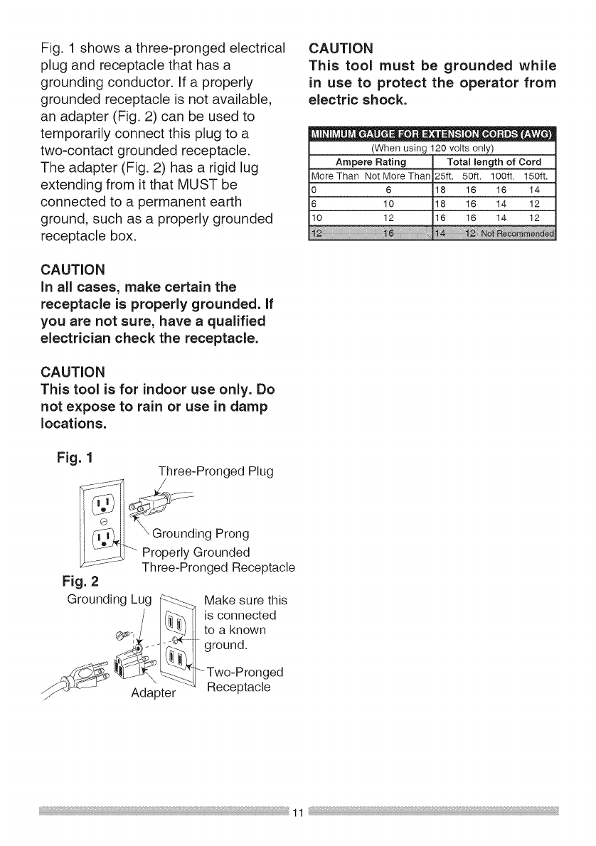
Fig.1showsathree-prongedelectrical
plugandreceptaclethathasa
groundingconductor.Ifa properly
groundedreceptacleisnotavailable,
anadapter(Fig.2)canbeusedto
temporarilyconnectthisplugtoa
two-contactgroundedreceptacle.
Theadapter(Fig.2)hasa rigidlug
extendingfromit thatMUSTbe
connectedtoa permanentearth
ground,suchasa properlygrounded
receptaclebox.
CAUTION
In all cases, make certain the
receptacle is properly grounded. If
you are not sure, have a qualified
electrician check the receptacle.
CAUTION
This tool is for indoor use only. Do
not expose to rain or use in damp
locations.
Fig. 1 Three-Pronged Plug
CAUTION
This tool must be grounded while
in use to protect the operator from
electric shock.
O" 0 O=t
(When using 120 volts only)
Ampere Rating Total length of Cord
More Than Not More Than 25ft. 50ft. 100ft. 150ft.
0 6 18 16 16 14
6 10 18 16 14 12
10 12 16 16 14 12
:::::::::::::::::::::::::::::::
g Prong
Properly Grounded
Three-Pronged Receptacle
Fig. 2
Grounding Lug _ Make sure this
/_'_ ] is connected
_b_-,./ I_. to a known
,_"_.__!_ II ground.
Two-Pronged
_zrt.J Adapter '_ Receptacle
RECOMMENDED ACCESSORIES
i_ WARNING ]
Visit your Sears Hardware
Department or see the
Craftsman Power and Hand Tools
Catalog to purchase recommended
accessories for this power tool.
[_ WARNING]
To avoid the risk of personal injury:
o Do not use adjustable (wobble)
type dadoes or carbide tipped
dado blades.
e Only use stackable dadoes.
e Maximum dado width is 1/2 in.
e Do not use adado with a diameter
larger than 6 in.
•Do not use molding head set with
this saw.
e Do not modify this power
tool or use accessories not
recommended by Sears.
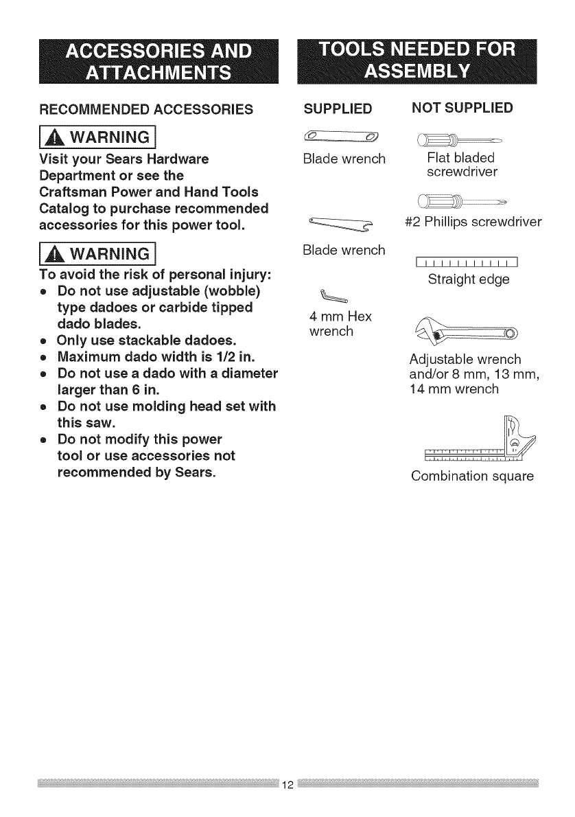
SUPPLIED
Blade wrench
NOT SUPPLIED
Flat bladed
screwdriver
Blade wrench
4 mm Hex
wrench
#2 Phillips screwdriver
I!!!!!!!!!!!
Straight edge
Adjustable wrench
and/or 8 mm, 13 mm,
14 mm wrench
Combination square

Separate all parts from packing
materials. Check each part with the
illustration on the next page and the
"Table of Loose Parts" to make certain
all items are accounted for, before
discarding any packing material.
I,A WARNING ]
if any part is missing or damaged,
do not attempt to assemble the
table saw, plug in the power
TABLE OF LOOSE PARTS
cord, or turn the switch ON until
the missing or damaged part is
obtained and is installed correctly.
Call 1=800-843-1682 for missing or
damaged parts.
NOTE: To make assembly easier, keep
contents of box together. Apply a coat
of automobile wax to the table. Wipe all
parts thoroughly with a clean dry cloth.
This will reduce friction when pushing
the workpeice.
ITEM
A
B
C
D
E
F
G
H
I
J
K
L
M
N
O
P
Q
R
S
T
STAND
U
V
W
X
Y
Z
AA
BB
CC
DESCRIPTION
Table saw assembly
Blade guard assembly
Anti-kickback pawls assembly
Handwheel handle
Riving knife hardware bag assembly
Rip fence
Miter gauge
Blade wrench
Push stick
Push stick storage holder
Rear table extension
Rear table extension tube
Table insert
Table extension wing hardware bag assembly
Hex wrench
Blade
Left and right extension table
Dust ba,q
Extension table hardware bag assembly
AAA Battery
QUANTITY
1
1
1
1
1
1
1
2
1
1
1
2
1
1
1
1
1 each
1
1
2
Locking lever hardware bag assembly
Stand hardware bag assembly
Leq bracket
Bottom Ionq support bracket
Top long support bracket
Bottom support bracket for roller wheel
Bottom short support bracket
Top short support bracket
Roller wheel hardware bag assembly
1
1
4
2
2
1
1
2
1
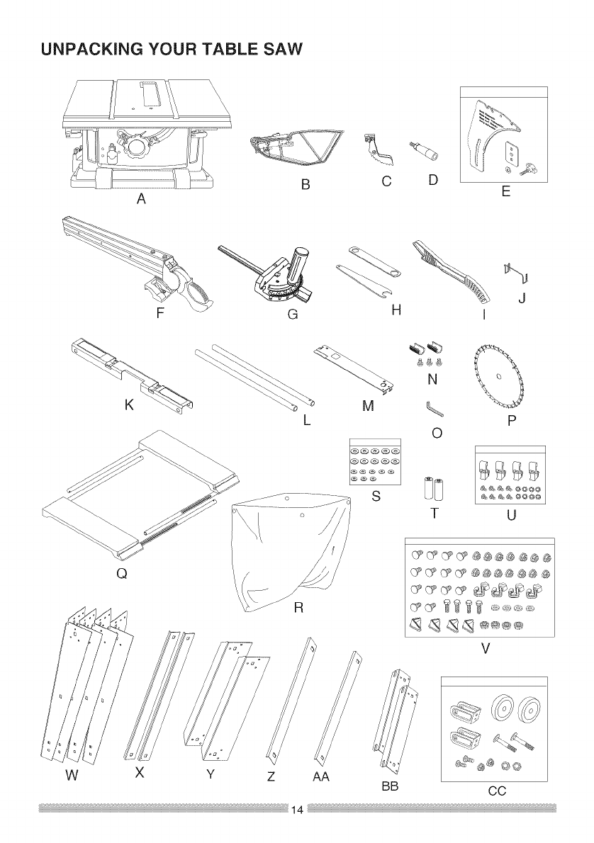
UNPACKING YOUR TABLE SAW
AB O D E
F G H
L
S
BB
N
O
T
%
J
I
P
U
Q
V
W X Y Z AA
GO
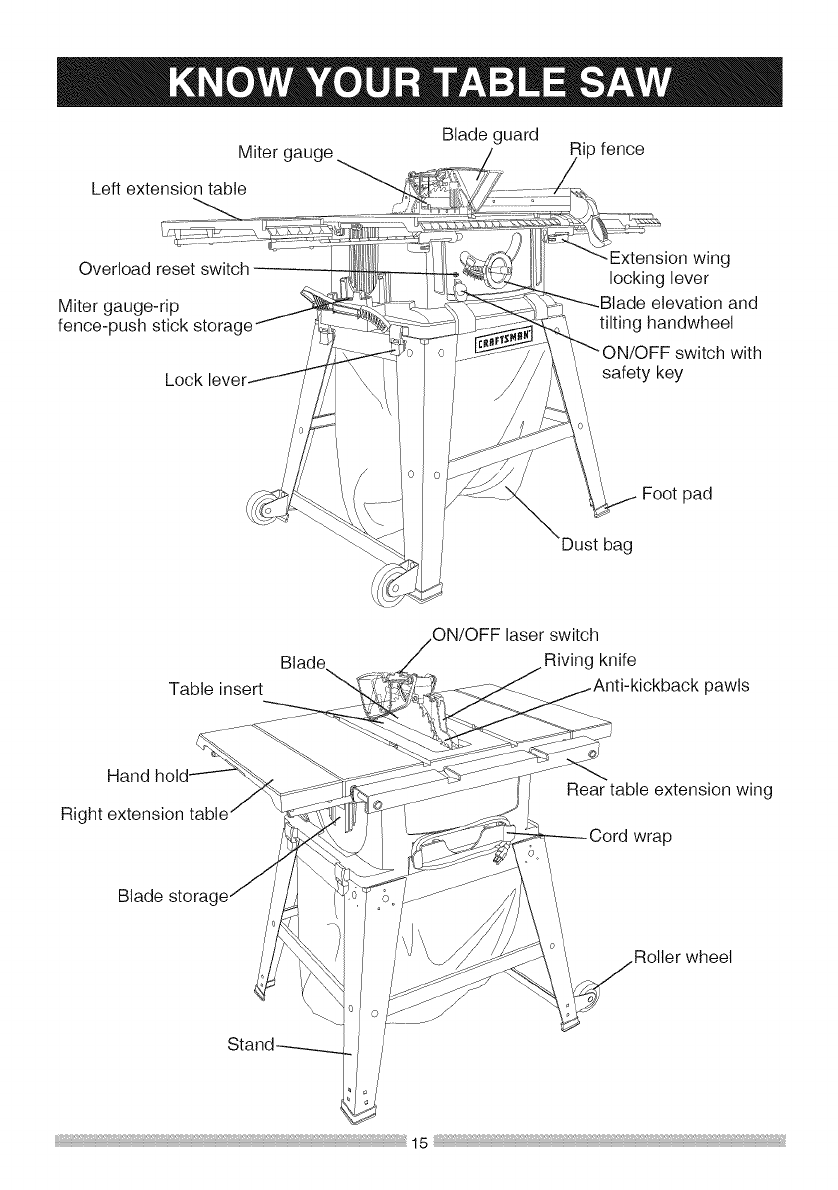
Blade guard
Miter gauge _ip fence
Left extension table
Overload reset switch
Miter gauge-rip
fence-push stick storac
Lock
wing
locking lever
elevation and
tilting handwheet
ON/OFF switch with
safety key
Footpad
Dustbag
Blade
Table insert
switch
Riving knife
pawls
Hand
Right extension
Rear table extension wing
wrap
Blade storac
Roller wheel
ANTI-KICKBACK PAWLS - Prevents
the workpiece from being kicked
upward or back toward the front of the
table saw by the spinning blade.
ARBOR - The shaft on which the
blade or dado is mounted.
the workpiece from twisting during the
cutting operation.
GUM - A sticky sap from wood
products.
HEEL - Misalignment of the blade.
BEVEL CUT - An angle cut made
through the face of the workpiece.
JAMB NUT - Nut used to lock another
nut in place on a threaded rod or bolt.
BLADE BEVEL SCALE - Measures
the angle the blade is tilted when set
for a bevel cut.
BLADE ELEVATION AND TiLTiNG
HANDWHEEL = Raises and lowers
the blade or tilts the blade to angle
between 0° and 45° for bevel cuts.
BLADE GUARD - Clear plastic cover
that positions itself over the blade while
cutting.
KERF - The amount of material
removed by the blade cut.
MITER CUT - An angle cut made
across the width of the workpiece.
MITER GAUGE - A guide used for
crosscutting operations that slides
in the table top channels (grooves)
located on either side of the blade. It
helps make accurate straight or angle
crosscuts.
COMPOUND CUT - A simultaneous
bevel and miter cut.
CROSSCUT - A cut made across the
width of the workpiece.
DADO - Special cutting blades that are
used to cut grooves in a workpiece.
OVERLOAD RESET SWITCH -
Protects the motor if it overloads during
operation, provides a way to restart the
saw.
PUSH STICK- Used to push
workpieces when performing ripping
operations.
FREEHAND - Performing a cut without PUSH BLOCK - Used for ripping
using a rip fence, miter gauge, hold operation when the workpiece is too
down or other proper device to prevent narrow to use a push stick. Always use
a push block for rip widths less than 2 in.
FEATHERBOARD- Whenripping
aworkpieceonyourtablesaw,this
keepsitfirmlyandsafelyagainstthe
ripfence.Italsohelpspreventchatter,
gouging,anddangerouskickback.
REVOLUTIONSPER MINUTE (RPM)
- The number of turns completed by a
spinning object in one minute.
RIP FENCE - A guide used for rip
cutting which allows the workpiece to
cut straight.
RIPPING - Cutting with the grain of
the wood or along the length of the
workpiece.
RIVING KNIFE - A metal piece of the
guard assembly located behind and
moves with the blade. Slightly thinner
than the saw blade, it helps keep the
kerf open and prevents kickback.
SAW BLADE PATH - The area of the
workpiece or table top directly in line
with the travel of the blade or the part
of the workpiece that will be cut.
SET - The distance between two saw
blade tips, bent outward in opposite
directions to each other. The further
apart the tips are, the greater the set.
TABLE INSERT - Insert that is
removed from the table to install/
remove blades. It is also removed for
dado cutting. When dado cutting, a
dado insert plate must be used.
THROUGH SAWING - Making a cut
completely through the length or width
of a workpiece.
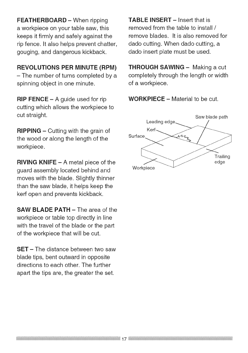
WORKPIECE - Material to be cut.
Leadinc Saw blade path
Workpiece
Trailing
edge
17
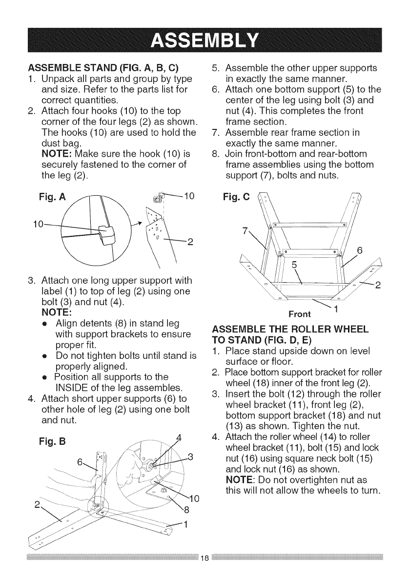
ASSEMBLE STAND (FIG. A, B, C)
1. Unpack all parts and group by type
and size. Refer to the parts list for
correct quantities.
2. Attach four hooks (10) to the top
corner of the four legs (2) as shown.
The hooks (10) are used to hold the
dust bag.
NOTE: Make sure the hook (10) is
securely fastened to the corner of
the leg (2).
5. Assemble the other upper supports
in exactly the same manner.
6. Attach one bottom support (5) to the
center of the leg using bolt (3) and
nut (4). This completes the front
frame section.
7. Assemble rear frame section in
exactly the same manner.
8. Join front-bottom and rear-bottom
frame assemblies using the bottom
support (7), bolts and nuts.
Fig. A_. .... 10 Fig. C
3. Attach one long upper support with
label (1) to top of leg (2) using one
bolt (3) and nut (4).
NOTE:
o Align detents (8) in stand leg
with support brackets to ensure
proper fit.
o Do not tighten bolts until stand is
properly aligned.
o Position all supports to the
INSIDE of the leg assembles.
4. Attach short upper supports (6) to
other hole of leg (2) using one bolt
and nut.
Fig. B
Front
ASSEMBLE THE ROLLER WHEEL
TO STAND (FIG. D, E)
1. Place stand upside down on level
surface or floor.
2. Place bottom support bracket for roller
wheel (18) innerof the front leg (2).
3. Insert the bolt (12) through the roller
wheel bracket (11), front leg (2),
bottom support bracket (18) and nut
(13) as shown. Tighten the nut.
4. Attach the roller wheel (14) to roller
wheel bracket (11), bolt (15) and lock
nut (16) using square neck bolt (15)
and lock nut (16) as shown.
NOTE: Do not overtighten nut as
this will not allow the wheels to turn.
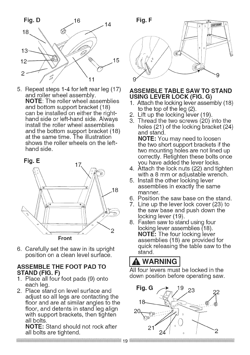
Fig.D 16 Fig. F
15
11
.Repeat steps 1-4 for left rear leg (17)
and roller wheel assembly.
NOTE: The roller wheel assemblies
and bottom support bracket (18)
can be installed on either the right-
hand side or left-hand side. Always
install the roller wheel assemblies
and the bottom support bracket (18)
at the same time. The illustration
shows the roller wheels on the left-
hand side.
Fig. E
Front
6. Carefully set the saw in its upright
position on a clean level surface.
ASSEMBLE THE FOOT PAD TO
STAND (FIG. F)
1. Place all four foot pads (9) onto
each leg.
2. Place stand on level surface and
adjust so all legs are contacting the
floor and are at similar angles to the
floor, and detents in stand leg align
with support brackets, then tighten
all bolts.
NOTE: Stand should not rock after
all bolts are tightend.
ASSEMBLE TABLE SAW TO STAND
USING LEVER LOCK (FIG. G)
1. Attach the locking lever assembly (18)
to the top of the leg (2).
2. Lift up the locking lever (19).
3. Thread the two screws (20) into the
holes (21) of the locking bracket (24)
and stand.
NOTE: You may need to loosen
the two short support brackets if the
two mounting holes are not lined up
correctly. Retighten these bolts once
you have added the lever locks.
4. Attach the lock nuts (22) and tighten
with a 8 mm or adjustable wrench.
5. Install the other locking lever
assemblies in exactly the same
manner.
6. Position the saw base on the stand.
7. Line up the lever lock cover (23) to
the saw base and push down the
locking lever (19).
8. Fasten saw to stand using four
locking lever assemblies (18).
NOTE: The four locking lever
assemblies (18) are provided for
quick releasing the table saw to the
stand.
I,'_ WARNING]
All four levers must be locked in the
down position before operating saw.
Fig. G _ 19 23
1._2
21
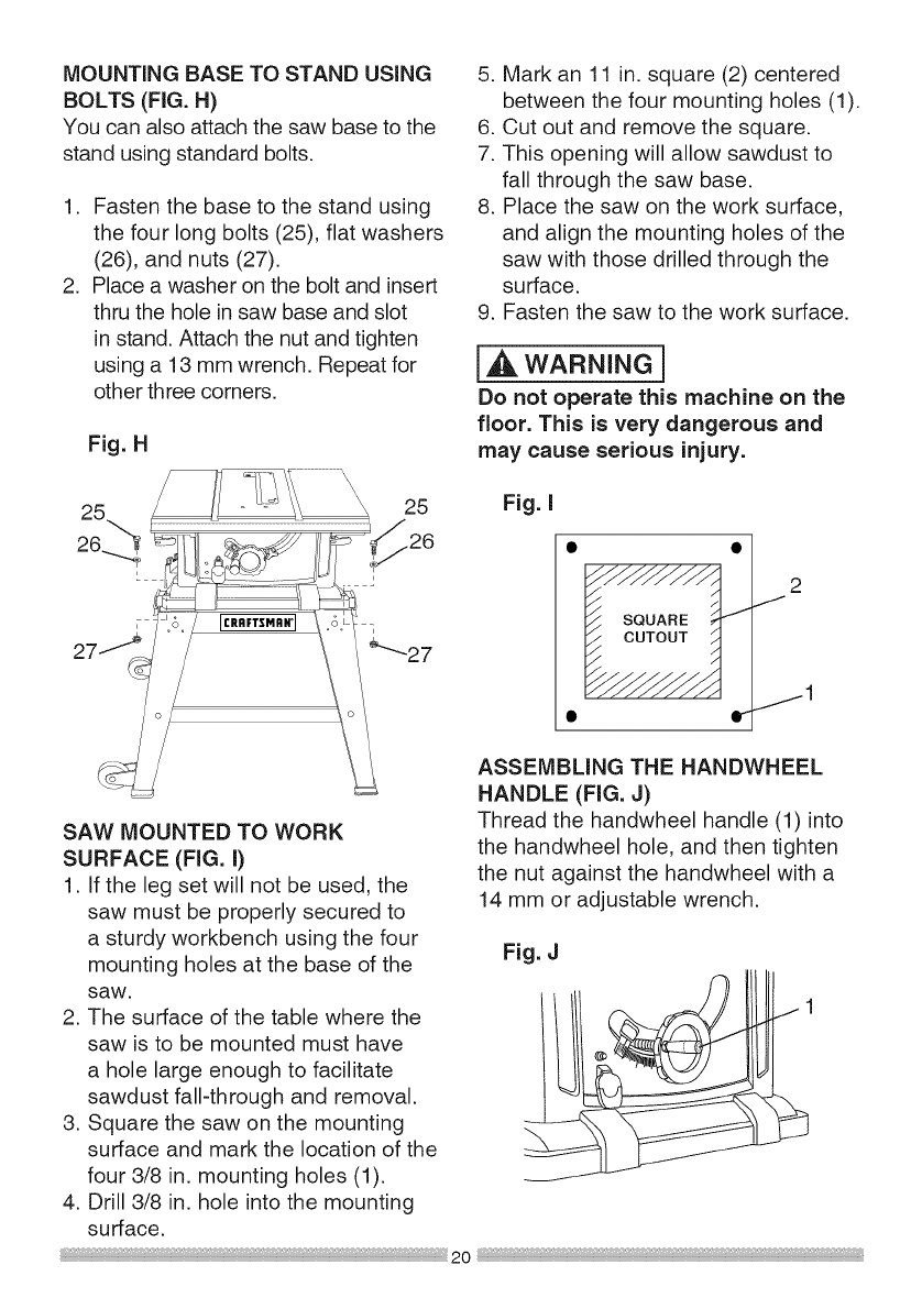
MOUNTING BASE TO STAND USING
BOLTS (FIG. H)
You can also attach the saw base to the
stand using standard bolts.
,
,
Fasten the base to the stand using
the four long bolts (25), flat washers
(26), and nuts (27).
Place a washer on the bolt and insert
thru the hole in saw base and slot
in stand. Attach the nut and tighten
using a 13 mm wrench. Repeat for
other three corners.
Fig. H
5. Mark an 11 in. square (2) centered
between the four mounting holes (1).
6. Cut out and remove the square.
7. This opening will allow sawdust to
fall through the saw base.
8. Place the saw on the work surface,
and align the mounting holes of the
saw with those drilled through the
surface.
9. Fasten the saw to the work surface.
l_k WARNING 1
Do not operate this machine on the
floor. This is very dangerous and
may cause serious injury.
27
25
SAW MOUNTED TO WORK
SURFACE (FIG. I)
1. If the leg set will not be used, the
saw must be properly secured to
a sturdy workbench using the four
mounting holes at the base of the
saw.
2. The surface of the table where the
saw is to be mounted must have
a hole large enough to facilitate
sawdust fall-through and removal.
3. Square the saw on the mounting
surface and mark the location of the
four 3/8 in. mounting holes (1).
4. Drill 3/8 in. hole into the mounting
surface.
Fig. I
i •
I_/SQUARE _-
co,oo,
JJJJJJ
• Ir
2
J
jl
ASSEMBLING THE HANDWHEEL
HANDLE (FIG. J)
Thread the handwheel handle (1) into
the handwheel hole, and then tighten
the nut against the handwheel with a
14 mm or adjustable wrench.
Fig. J
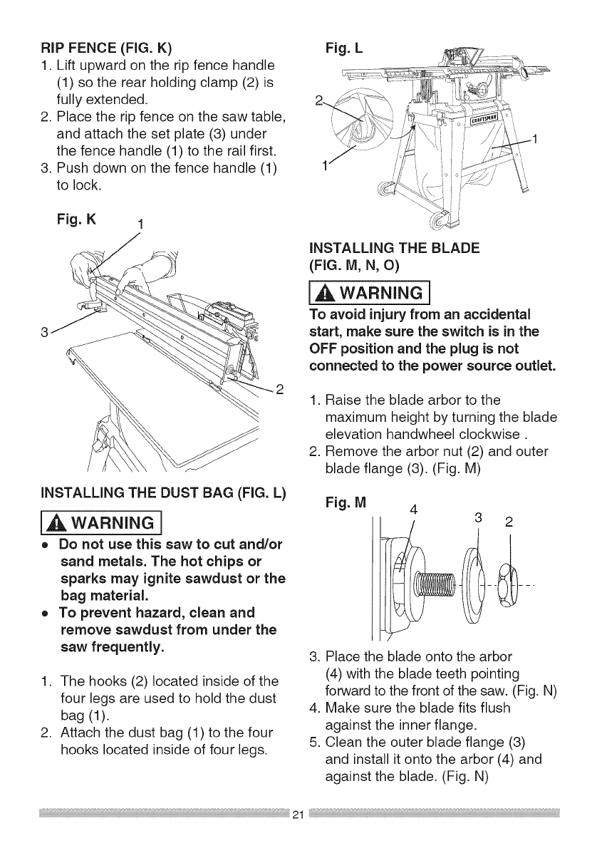
RiP FENCE (FIG. K)
1. Lift upward on the rip fence handle
(1) so the rear holding clamp (2) is
fully extended.
2. Place the rip fence on the saw table,
and attach the set plate (3) under
the fence handle (1) to the rail first.
3. Push down on the fence handle (1)
to lock.
Fig. K 1
iNSTALLiNG THE DUST BAG (FIG. L)
[_ WARNING]
o Do not use this saw to cut and/or
sand metals. The hot chips or
sparks may ignite sawdust or the
bag material.
o To prevent hazard, clean and
remove sawdust from under the
saw frequently.
1. The hooks (2) located inside of the
four legs are used to hold the dust
bag (1).
2. Attach the dust bag (1) to the four
hooks located inside of four legs.
Fig. L
INSTALLING THE BLADE
(FIG. M, N, O)
i_ WARNING]
To avoid injury from an accidental
start, make sure the switch is in the
OFF position and the plug is not
connected to the power source outlet.
1. Raise the blade arbor to the
maximum height by turning the blade
elevation handwheel clockwise.
2. Remove the arbor nut (2) and outer
blade flange (3). (Fig. M)
Fig. M 43 2
3. Place the blade onto the arbor
(4) with the blade teeth pointing
forward to the front of the saw. (Fig. N)
4. Make sure the blade fits flush
against the inner flange.
5. Clean the outer blade flange (3)
and install it onto the arbor (4) and
against the blade. (Fig. N)
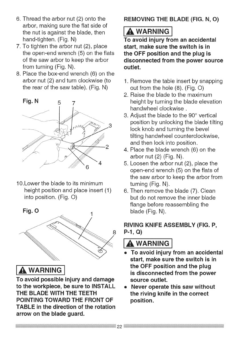
6.Threadthearbornut(2)ontothe
arbor,makingsuretheflatsideof
thenutisagainsttheblade,then
hand-tighten.(Fig.N)
7.Totightenthearbornut(2),place
theopen-endwrench(5)ontheflats
ofthesawarborto keepthearbor
fromturning(Fig.N).
8. Placethebox-endwrench(6)onthe
arbornut(2)andturnclockwise(to
therearofthesawtable).(Fig.N)
10.Lowerthebladetoitsminimum
heightpositionandplaceinsert(1)
intoposition.(Fig.O)
Fig. O
REMOVING THE BLADE (FIG. N, O)
I,A WARNING i
To avoid injury from an accidental
start, make sure the switch is in
the OFF position and the plug is
disconnected from the power source
outlet.
1. Remove the table insert by snapping
out from the hole (8). (Fig. O)
2. Raise the blade to the maximum
height by turning the blade elevation
handwheel clockwise.
3. Adjust the blade to the 90 ° vertical
position by unlocking the blade tilting
lock knob and turning the bevel
tilting handwheel counterclockwise,
and then lock into position.
4. Place the blade wrench (6) on the
arbor nut (2) (Fig. N).
5. Loosen the arbor nut (2), place the
open-end wrench (5) on the flats of
the saw arbor to keep the arbor from
turning (Fig. N).
6. Then remove the blade (7). Clean
but do not remove the inner blade
flange before reassembling the
blade (Fig. N).
8
[,_L,WARNING]
To avoid possible injury and damage
to the workpiece, be sure to INSTALL
THE BLADE WITH THE TEETH
POINTING TOWARD THE FRONT OF
TABLE in the direction of the rotation
arrow on the blade guard.
RIVING KNIFE ASSEMBLY (FIG. P,
P-I, Q)
[_, WARNING]
o To avoid injury from an accidental
start, make sure the switch is in
the OFF position and the plug
is disconnected from the power
source outlet.
o Never operate this saw without
the riving knife in the correct
position.
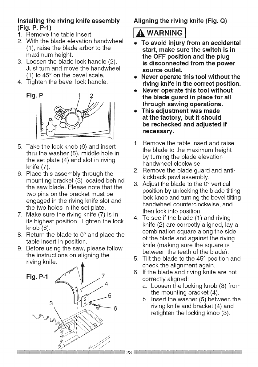
Installingthe riving knife assembly
(Fig. P, P=I)
1. Remove the table insert
2. With the blade elevation handwheel
(1), raise the blade arbor to the
maximum height.
3. Loosen the blade lock handle (2).
Just turn and move the handwheel
(1) to 45 ° on the bevel scale.
4. Tighten the bevel lock handle.
Fig. P1 2
5. Take the lock knob (6) and insert
thru the washer (5), middle hole in
the set plate (4) and slot in riving
knife (7).
6. Place this assembly through the
mounting bracket (3) located behind
the saw blade. Please note that the
two pins on the bracket must be
engaged in the riving knife slot and
the two holes in the set plate.
7. Make sure the riving knife (7) is in
its highest position. Tighten the lock
knob (6).
8. Return the blade to 0° and place the
table insert in position.
9. Before using the saw, please follow
the instructions on aligning the
riving knife, l
Fig. P-1 3 _54
Aligning the riving knife (Fig. Q)
I,A WARNING 1
o To avoid injury from an accidental
start, make sure the switch is in
the OFF position and the plug
is disconnected from the power
source outlet.
o Never operate this tool without the
riving knife in the correct position.
o Never operate this tool without
the blade guard in place for all
through sawing operations.
o This adjustment was made
at the factory, but it should
be rechecked and adjusted if
necessary.
1. Remove the table insert and raise
the blade to the maximum height
by turning the blade elevation
handwheel clockwise.
2. Remove the blade guard and anti-
kickback pawl assembly.
3. Adjust the blade to the 0° vertical
position by unlocking the blade tilting
lock knob and turning the bevel tilting
handwheel counterclockwise, and
then lock into position.
4. To see if the blade (1) and riving
knife (2) are correctly aligned, lay a
combination square along the side
of the blade and against the riving
knife (making sure the square is
between the teeth of the blade).
5. Tilt the blade to the 45° position and
check the alignment again.
6. If the blade and riving knife are not
correctly aligned:
a. Loosen the locking knob (3) from
the mounting bracket (4).
b. Insert the washer (5) between the
6 riving knife and bracket (4) and
\h__, retighten the locking knob (3).
NOTE:
o Thewashers(1/4"1/2-3/32)(5)are
notincludedwiththistablesaw.It
mustbepurchasedseparately.
o Rivingknifethicknessis0.09in.
o Themaximumradialdistance
betweentherivingknifeandthe
toothedrimofthesawbladeis0.12
in- 0.31in.(3mm- 8 mm)
o Thetipoftherivingknifeshallnot
belowerthan0.04in._ 0.2in.(1
mm_ 5mm)fromthetoothpeak.
o Therivingknifeisthinnerthanthe
widthofthekerfbyapproximately
1/64inoneachside.
8. Checktherivingknifeandblade
alignmentagainatboth0° and45°.
9. Addorremovethewashersuntilthe
alignmentiscorrect.
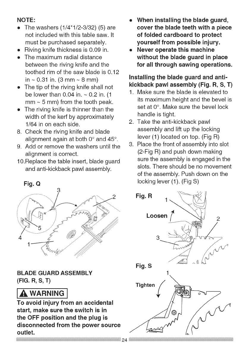
10.Replacethetableinsert,bladeguard
andanti-kickbackpawlassembly.
Fig.Q 3
41
BLADEGUARDASSEMBLY
(FIG.B,S,T)
i_ WARNING]
To avoid injury from an accidental
start, make sure the switch is in
the OFF position and the plug is
disconnected from the power source
outlet.
oWhen installing the blade guard,
cover the blade teeth with a piece
of folded cardboard to protect
yourself from possible injury.
o Never operate this machine
without the blade guard in place
for all through sawing operations.
installing the blade guard and anti=
kickback pawl assembly (Fig. R, S, T)
1. Make sure the blade is elevated to
its maximum height and the bevel is
set at 0°. Make sure the bevel lock
handle is tight.
2. Take the anti-kickback pawl
assembly and lift up the locking
lever (1) located on top. (Fig R)
3. Place the front of assembly into slot
(2-Fig R) and push down making
sure the assembly is engaged in the
slots. There should be no movement
of the assembly. Push down on the
locking lever (1). (Fig S)
Tighten
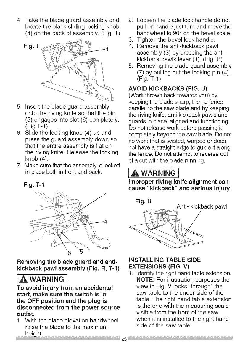
.Take the blade guard assembly and
locate the black sliding locking knob
(4) on the back of assembly. (Fig. T)
Fig. T
5. Insert the blade guard assembly
onto the riving knife so that the pin
(5) engages into slot (6) completely.
(Fig T-I)
6. Slide the locking knob (4) up and
press the guard assembly down so
that the entire assembly is flat on
the riving knife. Release the locking
knob (4).
7. Make sure that the assembly is locked
in place both in front and back.
Fig. T-1
2. Loosen the blade lock handle do not
pull on handle just turn and move the
handwheel to 90° on the bevel scale.
3. Tighten the bevel lock handle.
4. Remove the anti-kickback pawl
assembly (3) by pressing the anti-
kickback pawls lever (1). (Fig. R)
5. Removing the blade guard assembly
(7) by pulling out the locking pin (4).
(Fig. T-l)
AVOID KICKBACKS (FIG. U)
(Work thrown back towards you) by
keeping the blade sharp, the rip fence
parallel to the saw blade and by keeping
the riving knife, anti-kickback pawls and
guards in place, aligned and functioning.
Do not release work before passing it
completely beyond the saw blade. Do not
rip work that is twisted, warped or does
not have a straight edge to guide it along
the fence. Do not attempt to reverse out
of a cut with the blade running.
I,_ WARNING I
Improper riving knife alignment can
cause "kickback" and serious injury.
Fig. U Anti- kickback pawl
Removing the blade guard and anti-
kickback pawl assembly (Fig. R, T-l)
i_ WARNING]
To avoid injury from an accidental
start, make sure the switch is in
the OFF position and the plug is
disconnected from the power source
outlet.
1. With the blade elevation handwheel
raise the blade to the maximum
height:
iNSTALLING TABLE SIDE
EXTENSIONS (FIG. V)
1. Identify the right hand table extension.
NOTE: For illustration purposes the
view in Fig. V looks "through" the
saw table to the under side of the
table. The right hand table extension
is the one with the measuring scale
visible from the front of the saw
when it is installed to the right hand
side of the saw table.
2. Unlockbothfrontandrearcam
lockinglevers(1)ontherighthand
sideofthesawbasebyflippingthe
leverover.
3. Insertthetableextensionmounting
tubes(2)intothetwomatching
holesinthecamleverassemblies.
NOTE:Makesurethefrontmounting
tubehasthemeasuringscalevisible
fromthefrontofthesaw.
4. Slidethetableextensiontowardthe
tableuntilit restsagainstthesaw
table.
5. Lockbothcamlockingleversby
pushingthemintowardthecam
lockingleverassemblies.
6. Iftheextensionisnotleveltothe
table,adjustbyinsertingthespacers
(CartonContentsS)betweenthe
extensionandthetubeit mounts
onto.Seepage35.
Fig. V
7. Make sure the screw (3) into the
matching hole (4) of the extension
mounting tube (2).
8. Install the left hand table extension
the same manner.
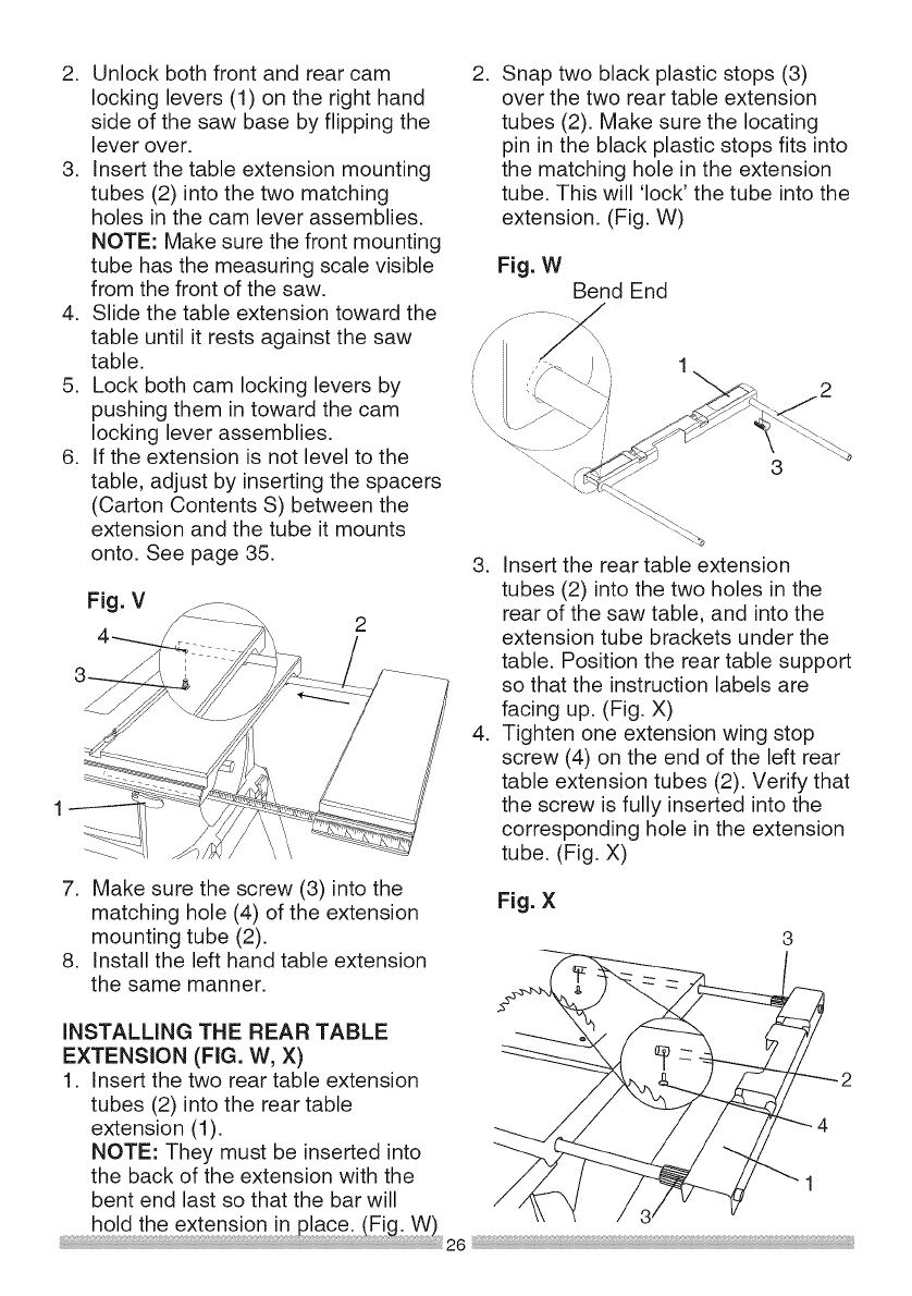
.Snap two black plastic stops (3)
over the two rear table extension
tubes (2). Make sure the locating
pin in the black plastic stops fits into
the matching hole in the extension
tube. This will 'lock' the tube into the
extension. (Fig. W)
Fig. WBend End
3
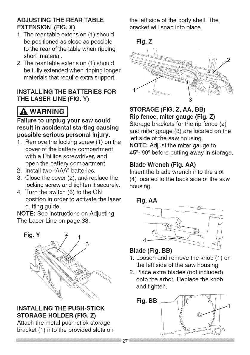
3. Insert the rear table extension
tubes (2) into the two holes in the
rear of the saw table, and into the
extension tube brackets under the
table. Position the rear table support
so that the instruction labels are
facing up. (Fig. X)
4. Tighten one extension wing stop
screw (4) on the end of the left rear
table extension tubes (2). Verify that
the screw is fully inserted into the
corresponding hole in the extension
tube. (Fig. X)
Fig. X
INSTALLING THE REAR TABLE
EXTENSION (FIG. W, X)
1. Insert the two rear table extension
tubes (2) into the rear table
extension (1).
NOTE: They must be inserted into
the back of the extension with the
bent end last so that the bar will
ADJUSTING THE REAR TABLE
EXTENSION (FIG. X)
1. The rear table extension (1) should
be positioned as close as possible
to the rear of the table when ripping
short material.
2. The rear table extension (1) should
be fully extended when ripping longer
materials that require extra support.
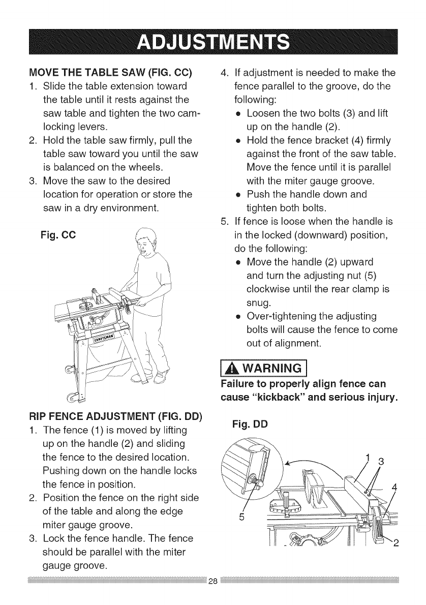
iNSTALLING THE BATTERIES FOR
THE LASER LINE (FIG. Y)
[,_ WARNING]
Failure to unplug your saw could
result in accidental starting causing
possible serious personal injury.
1. Remove the locking screw (1) on the
cover of the battery compartment
with a Phillips screwdriver, and
open the battery compartment.
2. Install two "AAA" batteries.
3. Close the cover (2), and replace the
locking screw and tighten it securely.
4. Turn the switch (3) to the ON
position in order to activate the laser
cutting guide.
NOTE: See instructions on Adjusting
The Laser Line on page 33.
Fig. Y 1
3
the left side of the body shell. The
bracket will snap into place.
Fig. Z
\
3
STORAGE (FIG. Z, AA, BB)
Rip fence, miter gauge (Fig. Z)
Storage brackets for the rip fence (2)
and miter gauge (3) are located on the
left side of the saw housing.
NOTE: Adjust the miter gauge to
45°-60 ° before putting away in storage.
Blade Wrench (Fig. AA)
Insert the blade wrench into the slot
(4) located to the back side of the saw
housing.
Fig. AA
4
Blade (Fig. BB)
1. Loosen and remove the knob (1) on
the left side of the saw housing.
2. Place extra blades (not included)
onto the arbor. Replace the knob
and tighten.
INSTALLING THE PUSH-STICK
STORAGE HOLDER (FIG. Z)
Attach the metal push-stick storage
bracket (1) into the provided slots on
Fig. BB
27
MOVE THE TABLE SAW (FIG. CC)
1. Slide the table extension toward
the table until it rests against the
saw table and tighten the two cam-
locking levers.
2. Hold the table saw firmly, pull the
table saw toward you until the saw
is balanced on the wheels.
3. Move the saw to the desired
location for operation or store the
saw in a dry environment.
Fig. CC
RiP FENCE ADJUSTMENT (FIG. DD)
1. The fence (1) is moved by lifting
up on the handle (2) and sliding
the fence to the desired location.
Pushing down on the handle locks
the fence in position.
2. Position the fence on the right side
of the table and along the edge
miter gauge groove.
3. Lock the fence handle. The fence
should be parallel with the miter
gauge groove.
4. if adjustment is needed to make the
fence parallel to the groove, do the
following:
o Loosen the two bolts (3) and lift
up on the handle (2).
o Hold the fence bracket (4) firmly
against the front of the saw table.
Move the fence until it is parallel
with the miter gauge groove.
o Push the handle down and
tighten both bolts.
5. if fence is loose when the handle is
in the locked (downward) position,
do the following:
o Move the handle (2) upward
and turn the adjusting nut (5)
clockwise until the rear clamp is
snug.
o Over-tightening the adjusting
bolts will cause the fence to come
out of alignment.
I,A WARNING I
Failure to properly align fence can
cause "kickback" and serious injury.
Fig. DD
RiP FENCE iNDiCATOR
ADJUSTMENT (FIG. EE)
1. The rip fence indicator (6) points to
the measurement scale. The scale
shows the distance from the side of
the fence to nearest side of the blade.
2. Measure the actual distance with a
rule. if there is a difference between
the measurement and the indicator,
adjust the indicator (6).
3. Loosen the screw (7) and slide the
indicator to the correct measurement
on the scale. Tighten the screw and
remeasure with the rule.
Fig. EE
i_ WARNING]
To avoid injury from an accidental
start, make sure the switch is in the
OFF position and the plug is not
connected to the power source outlet.
3. To change angles on the miter gauge,
loosen the lock handle (1) and rotate
the miter body to the desired angle
as indicated by the scale. Secure in
position by tightening the lock handle.
Fig. FF
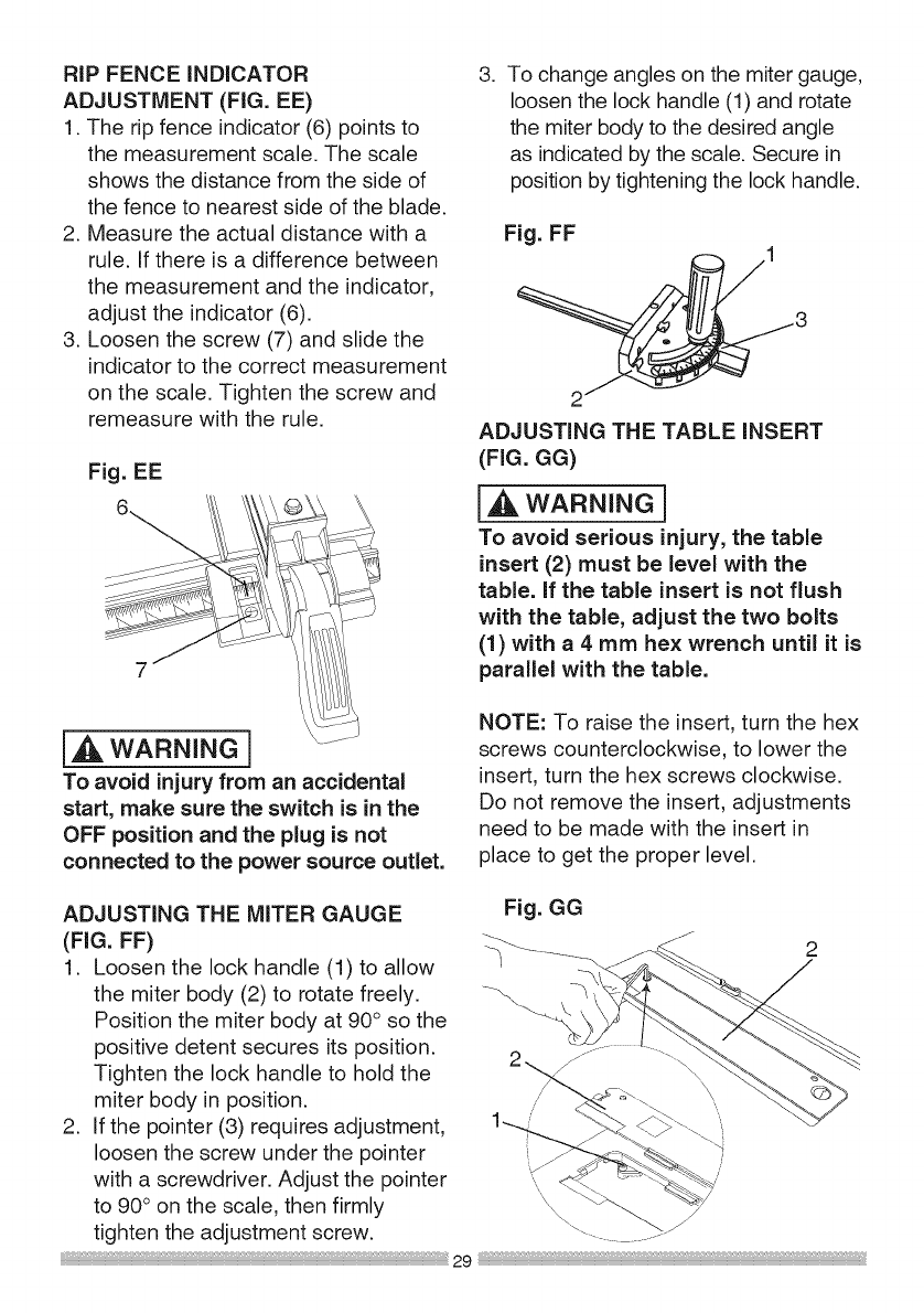
ADJUSTING THE TABLE iNSERT
(FIG. GG)
[_ WARNING]
To avoid serious injury, the table
insert (2) must be level with the
table, if the table insert is not flush
with the table, adjust the two bolts
(1) with a 4 mm hex wrench until it is
parallel with the table.
NOTE: To raise the insert, turn the hex
screws counterclockwise, to lower the
insert, turn the hex screws clockwise.
Do not remove the insert, adjustments
need to be made with the insert in
place to get the proper level.
ADJUSTING THE MITER GAUGE
(FIG. FF)
1. Loosen the lock handle (1) to allow
the miter body (2) to rotate freely.
Position the miter body at 90° so the
positive detent secures its position.
Tighten the lock handle to hold the
miter body in position.
2. If the pointer (3) requires adjustment,
loosen the screw under the pointer
with a screwdriver. Adjust the pointer
to 90° on the scale, then firmly
tighten the adjustment screw.
Fig. GG
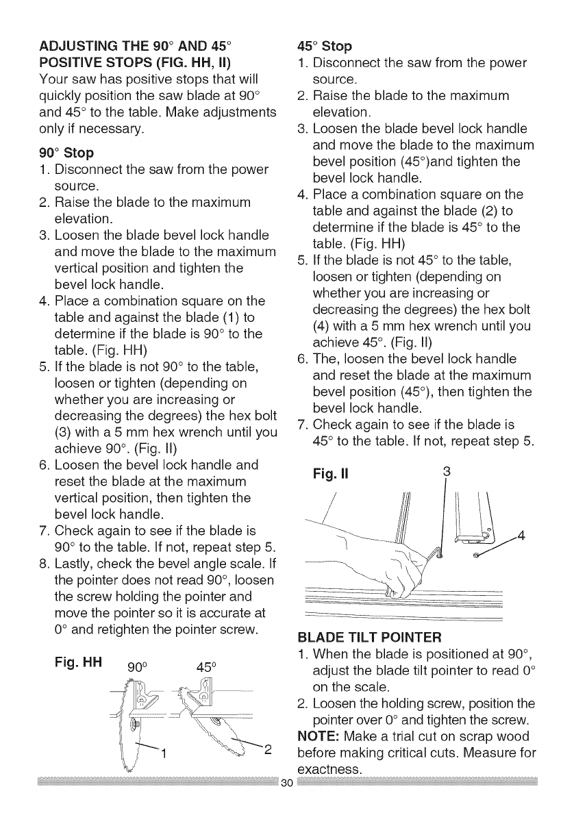
ADJUSTING THE 90 ° AND 45°
POSiTiVE STOPS (FIG. HH, ii)
Your saw has positive stops that will
quickly position the saw blade at 90 °
and 45° to the table. Make adjustments
only if necessary.
90° Stop
1. Disconnect the saw from the power
source.
2. Raise the blade to the maximum
elevation.
3. Loosen the blade bevel lock handle
and move the blade to the maximum
vertical position and tighten the
bevel lock handle.
4. Place a combination square on the
table and against the blade (1) to
determine if the blade is 90° to the
table. (Fig. HH)
5. If the blade is not 90° to the table,
loosen or tighten (depending on
whether you are increasing or
decreasing the degrees) the hex bolt
(3) with a 5 mm hex wrench until you
achieve 90°. (Fig. II)
6. Loosen the bevel lock handle and
reset the blade at the maximum
vertical position, then tighten the
bevel lock handle.
7. Check again to see if the blade is
90° to the table. If not, repeat step 5.
8. Lastly, check the bevel angle scale. If
the pointer does not read 90°, loosen
the screw holding the pointer and
move the pointer so it is accurate at
0° and retighten the pointer screw.
Fig. HH 900 450
45° Stop
1. Disconnect the saw from the power
source.
2. Raise the blade to the maximum
elevation.
3. Loosen the blade bevel lock handle
and move the blade to the maximum
bevel position (45°)and tighten the
bevel lock handle.
4. Place a combination square on the
table and against the blade (2) to
determine if the blade is 45° to the
table. (Fig. HH)
5. If the blade is not 45° to the table,
loosen or tighten (depending on
whether you are increasing or
decreasing the degrees) the hex bolt
(4) with a 5 mm hex wrench until you
achieve 45 °. (Fig. II)
6. The, loosen the bevel lock handle
and reset the blade at the maximum
bevel position (45°), then tighten the
bevel lock handle.
7. Check again to see if the blade is
45° to the table. If not, repeat step 5.
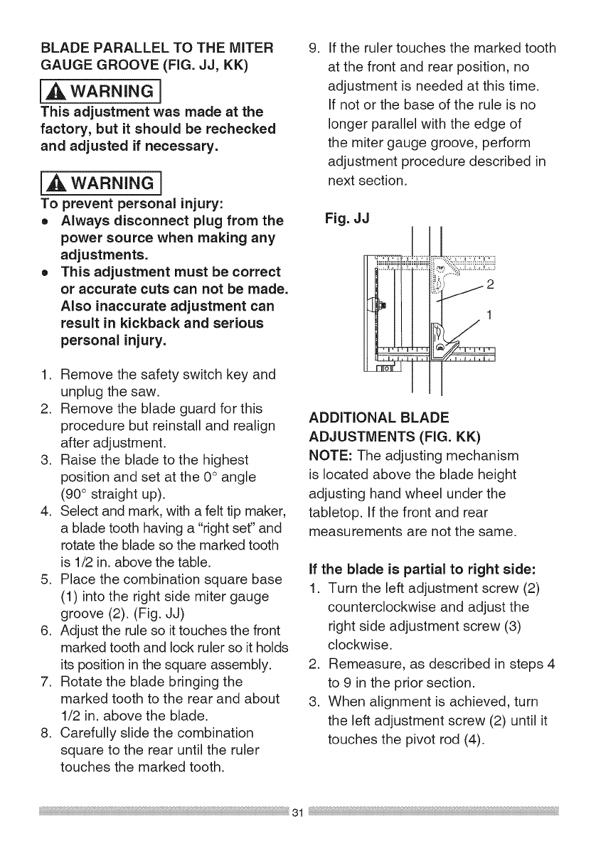
BLADE TiLT POINTER
1. When the blade is positioned at 90°,
adjust the blade tilt pointer to read 0°
on the scale.
2. Loosen the holding screw, position the
pointer over 0° and tighten the screw.
NOTE: Make a trial cut on scrap wood
before making critical cuts. Measure for
exactness.
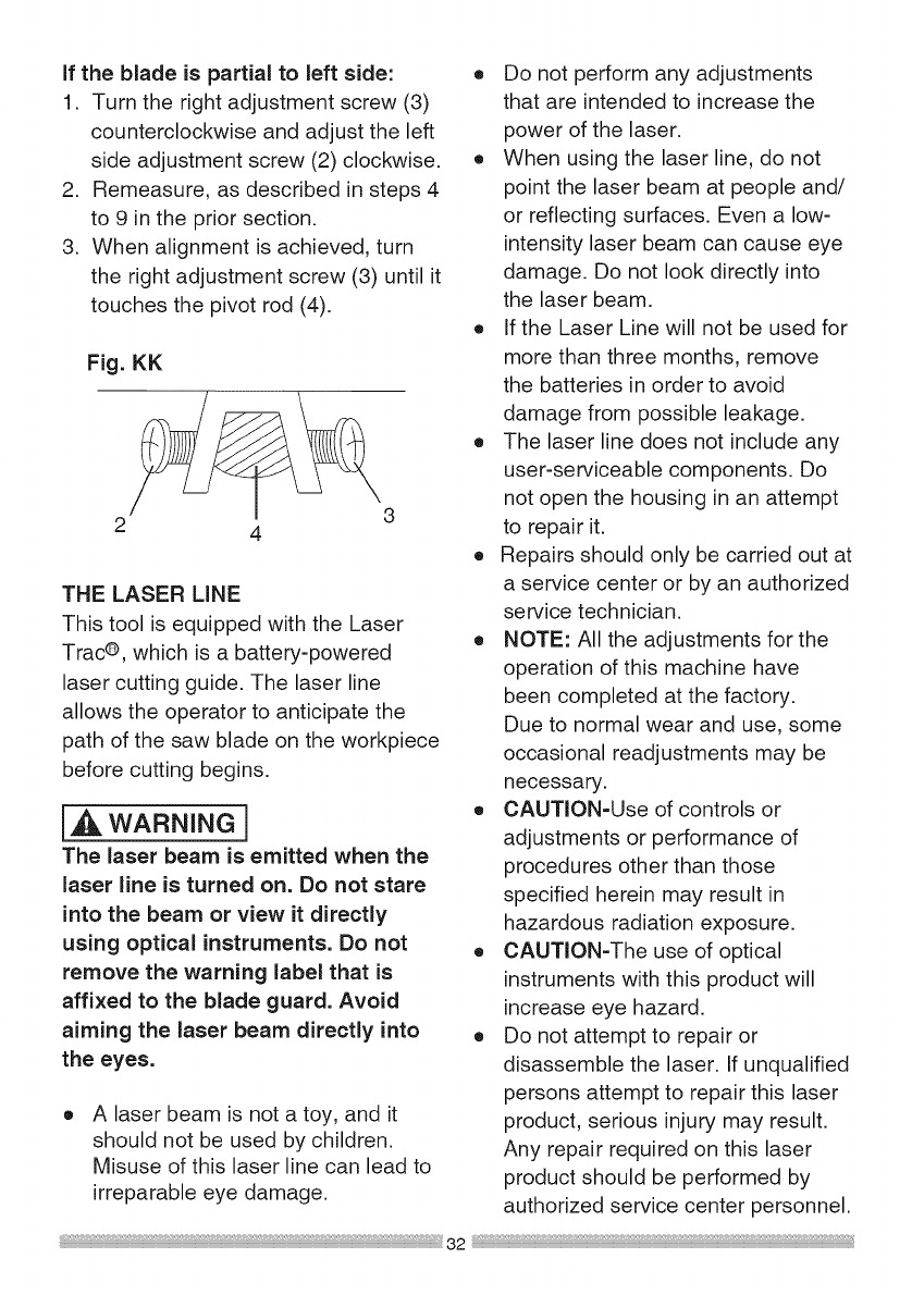
BLADEPARALLEL TO THE MITER
GAUGE GROOVE (FIG. JJ, KK)
I_ WARNING]
This adjustment was made at the
factory, but it should be rechecked
and adjusted if necessary.
i_ WARNING]
To prevent personal injury:
o Always disconnect plug from the
power source when making any
adjustments.
o This adjustment must be correct
or accurate cuts can not be made.
Also inaccurate adjustment can
result in kickback and serious
personal injury.
1. Remove the safety switch key and
unplug the saw.
2. Remove the blade guard for this
procedure but reinstall and realign
after adjustment.
3. Raise the blade to the highest
position and set at the 0° angle
(90° straight up).
4. Select and mark, with a felt tip maker,
a blade tooth having a "right set" and
rotate the blade so the marked tooth
is 1/2 in. above the table.
5. Place the combination square base
(1) into the right side miter gauge
groove (2). (Fig. JJ)
6. Adjust the rule so it touches the front
marked tooth and lock ruler so it holds
its position in the square assembly.
7. Rotate the blade bringing the
marked tooth to the rear and about
1/2 in. above the blade.
8. Carefully slide the combination
square to the rear until the ruler
touches the marked tooth.
.If the ruler touches the marked tooth
at the front and rear position, no
adjustment is needed at this time.
If not or the base of the rule is no
longer parallel with the edge of
the miter gauge groove, perform
adjustment procedure described in
next section.
Fig. JJ
iiiiiiiiiiiiii?iiiiiii!ii:iiii;iiiiii
j2
211 1
_aUI
ADDITIONAL BLADE
ADJUSTMENTS (FIG. KK)
NOTE: The adjusting mechanism
is located above the blade height
adjusting hand wheel under the
tabletop. If the front and rear
measurements are not the same.
if the blade is partial to right side:
1. Turn the left adjustment screw (2)
counterclockwise and adjust the
right side adjustment screw (3)
clockwise.
2. Remeasure, as described in steps 4
to 9 in the prior section.
3. When alignment is achieved, turn
the left adjustment screw (2) until it
touches the pivot rod (4).
Ifthebladeis partial to left side:
1. Turn the right adjustment screw (3)
counterclockwise and adjust the left
side adjustment screw (2) clockwise.
2. Remeasure, as described in steps 4
to 9 in the prior section.
3. When alignment is achieved, turn
the right adjustment screw (3) until it
touches the pivot rod (4).
Fig. KK
2 4
THE LASER LINE
This tool is equipped with the Laser
Trac®, which is a battery-powered
laser cutting guide. The laser line
allows the operator to anticipate the
path of the saw blade on the workpiece
before cutting begins.
i,_. WARNING]
The laser beam is emitted when the
laser line is turned on. Do not stare
into the beam or view it directly
using optical instruments. Do not
remove the warning label that is
affixed to the blade guard. Avoid
aiming the laser beam directly into
the eyes.
A laser beam is not a toy, and it
should not be used by children.
Misuse of this laser line can lead to
irreparable eye damage.
o Do not perform any adjustments
that are intended to increase the
power of the laser.
o When using the laser line, do not
point the laser beam at people and/
or reflecting surfaces. Even a low-
intensity laser beam can cause eye
damage. Do not look directly into
the laser beam.
o If the Laser Line will not be used for
more than three months, remove
the batteries in order to avoid
damage from possible leakage.
o The laser line does not include any
user-serviceable components. Do
not open the housing in an attempt
to repair it.
o Repairs should only be carried out at
a service center or by an authorized
service technician.
o NOTE: All the adjustments for the
operation of this machine have
been completed at the factory.
Due to normal wear and use, some
occasional readjustments may be
necessary.
o CAUTiON-Use of controls or
adjustments or performance of
procedures other than those
specified herein may result in
hazardous radiation exposure.
o CAUTiON-The use of optical
instruments with this product will
increase eye hazard.
o Do not attempt to repair or
disassemble the laser. If unqualified
persons attempt to repair this laser
product, serious injury may result.
Any repair required on this laser
product should be performed by
authorized service center personnel.
32
LASER RADIATION.
Do not stare into the beam or view it
directly using optical instruments.
Maximum output: < 1 mW
Wavelength: 630-670 nm
Complies with 21 CFR 1040.10 and
1040.11 Class II Laser Product.
Laser Warning Label:
\ _ /' LASER RAOIATION
oo NOT STARE INTO BEAM
MAX OUTPUT <ImW OlOOE LASER 630_670nrn
_and 104011
_50 CLASS tt LASER PROOUCTj
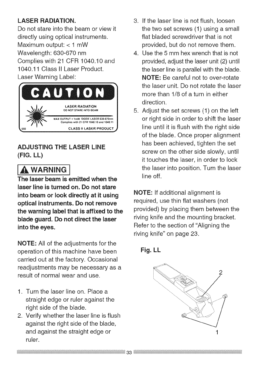
ADJUSTING THE LASER LINE
(FIG. LL)
[_ WARNING]
The laser beam is emitted when the
laser line is turned on. Do not stare
into beam or look directly at it using
optical instruments. Do not remove
the warning label that is affixed to the
blade guard. Do not direct the laser
into the eyes.
NOTE: All of the adjustments for the
operation of this machine have been
carried out at the factory. Occasional
readjustments may be necessary as a
result of normal wear and use.
1. Turn the laser line on. Place a
straight edge or ruler against the
right side of the blade.
2. Verify whether the laser line is flush
against the right side of the blade,
and against the straight edge or
ruler.
3. If the laser line is not flush, loosen
the two set screws (1) using a small
flat bladed screwdriver that is not
provided, but do not remove them.
4. Use the 5 mm hex wrench that is not
provided, adjust the laser unit (2) until
the laser line is parallel with the blade.
NOTE: Be careful not to over-rotate
the laser unit. Do not rotate the laser
more than 1/8 of a turn in either
direction.
5. Adjust the set screws (1) on the left
or right side in order to shift the laser
line until it is flush with the right side
of the blade. Once proper alignment
has been achieved, tighten the set
screw on the other side slowly, until
it touches the laser, in order to lock
the laser into position. Turn the laser
line off.
NOTE: If additional alignment is
required, use thin flat washers (not
provided) by placing them between the
riving knife and the mounting bracket.
Refer to the section of "Aligning the
riving knife" on page 23.
Fig. LL
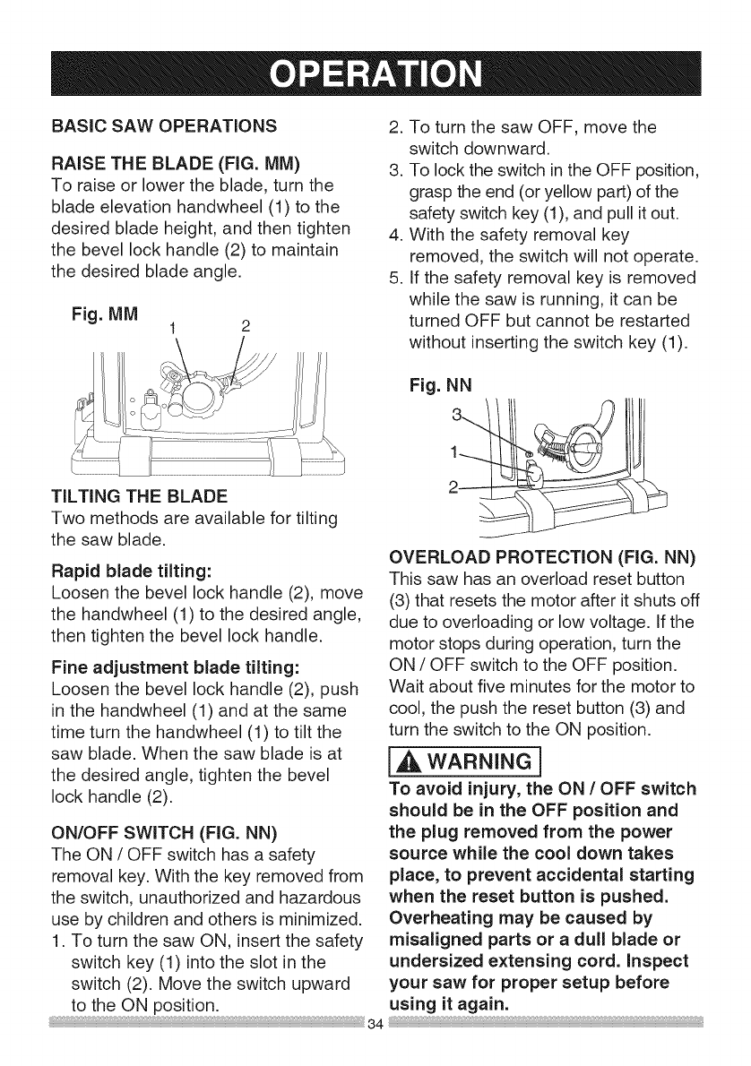
BASIC SAW OPERATIONS
RAISE THE BLADE (FIG. MM)
To raise or lower the blade, turn the
blade elevation handwheel (1) to the
desired blade height, and then tighten
the bevel lock handle (2) to maintain
the desired blade angle.
Fig. MM
2. To turn the saw OFF, move the
switch downward.
3. To lock the switch in the OFF position,
grasp the end (or yellow part) of the
safety switch key (1), and pull it out.
4. With the safety removal key
removed, the switch will not operate.
5. if the safety removal key is removed
while the saw is running, it can be
turned OFF but cannot be restarted
without inserting the switch key (1).
TiLTiNG THE BLADE
Two methods are available for tilting
the saw blade.
Rapid blade tilting:
Loosen the bevel lock handle (2), move
the handwheel (1) to the desired angle,
then tighten the bevel lock handle.
Fine adjustment blade tilting:
Loosen the bevel lock handle (2), push
in the handwheel (1) and at the same
time turn the handwheel (1) to tilt the
saw blade. When the saw blade is at
the desired angle, tighten the bevel
lock handle (2).
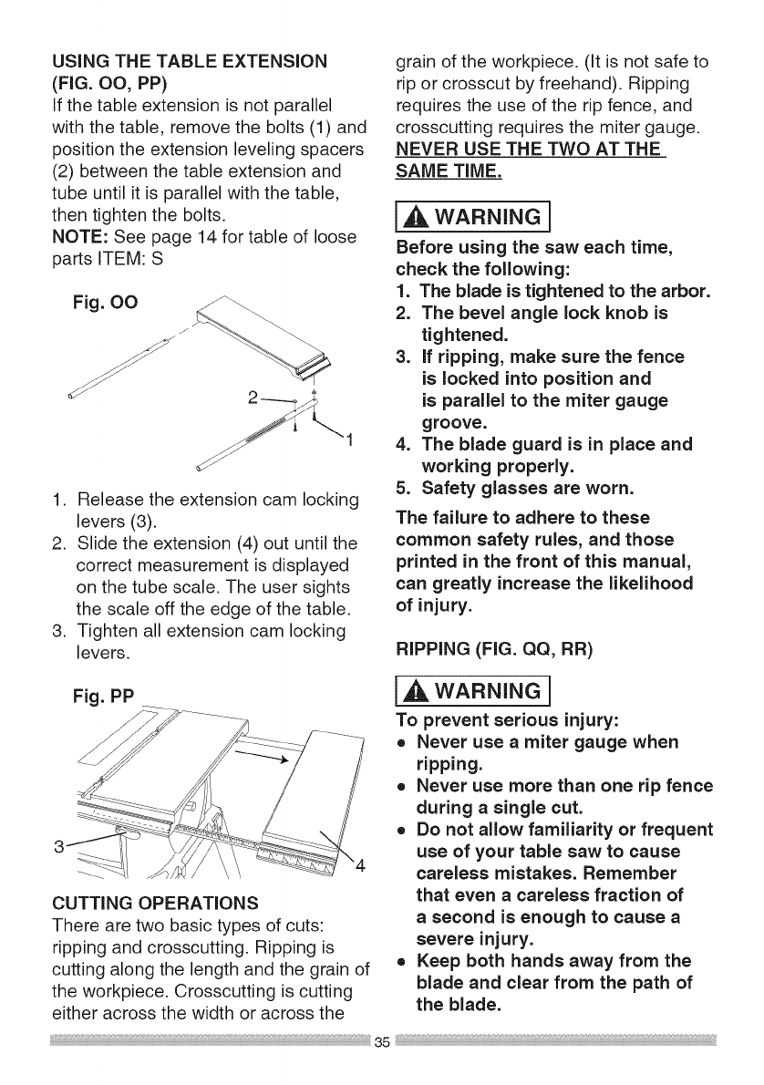
ON/OFF SWITCH (FIG. NN)
The ON /OFF switch has a safety
removal key. With the key removed from
the switch, unauthorized and hazardous
use by children and others is minimized.
1. To turn the saw ON, insert the safety
switch key (1) into the slot in the
switch (2). Move the switch upward
to the ON position.
Fig. NN
OVERLOAD PROTECTION (FIG. NN)
This saw has an overload reset button
(3) that resets the motor after it shuts off
due to overloading or low voltage, if the
motor stops during operation, turn the
ON /OFF switch to the OFF position.
Wait about five minutes for the motor to
cool, the push the reset button (3) and
turn the switch to the ON position.
[_ WARNING]
To avoid injury, the ON /OFF switch
should be in the OFF position and
the plug removed from the power
source while the cool down takes
place, to prevent accidental starting
when the reset button is pushed.
Overheating may be caused by
misaligned parts or a dull blade or
undersized extensing cord. inspect
your saw for proper setup before
using it again.
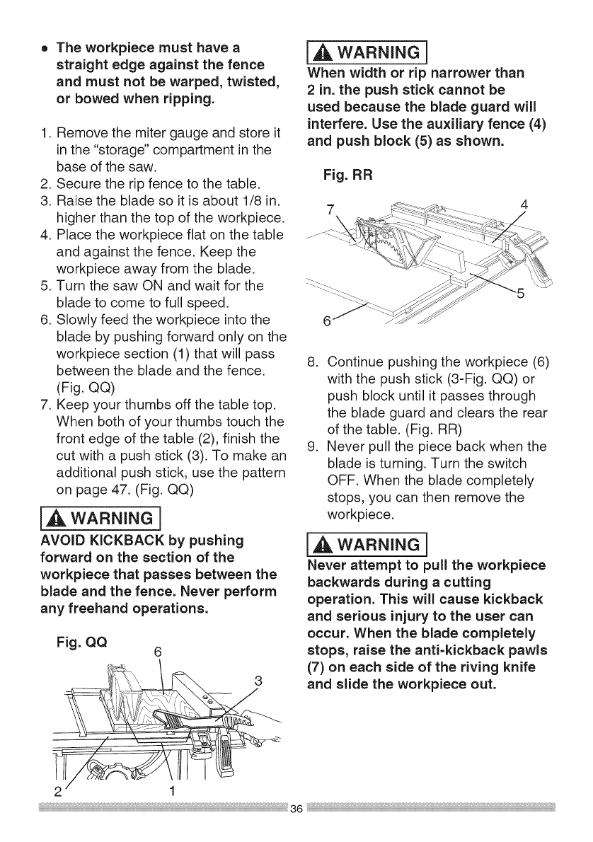
USINGTHE TABLE EXTENSION
(FIG. OO, PP)
If the table extension is not parallel
with the table, remove the bolts (1) and
position the extension leveling spacers
(2) between the table extension and
tube until it is parallel with the table,
then tighten the bolts.
NOTE: See page 14 for table of loose
parts ITEM: S
Fig. OO
J
1. Release the extension cam locking
levers (3).
2. Slide the extension (4) out until the
correct measurement is displayed
on the tube scale. The user sights
the scale off the edge of the table.
3. Tighten all extension cam locking
levers.
grain of the workpiece. (It is not safe to
rip or crosscut by freehand). Ripping
requires the use of the rip fence, and
crosscutting requires the miter gauge.
NEVER USE THE TWO AT THE
SAME TIME.
I_ WARNING]
Before using the saw each time,
check the following:
1. The blade is tightened to the arbor.
2. The bevel angle lock knob is
tightened.
3. If ripping, make sure the fence
is locked into position and
is parallel to the miter gauge
groove.
4. The blade guard is in place and
working properly.
5. Safety glasses are worn.
The failure to adhere to these
common safety rules, and those
printed in the front of this manual,
can greatly increase the likelihood
of injury.
RIPPING (FIG. QQ, RR)
Fig. PP
CUTTING OPERATIONS
There are two basic types of cuts:
ripping and crosscutting. Ripping is
cutting along the length and the grain of
the workpiece. Crosscutting is cutting
either across the width or across the
i_ WARNING I
To prevent serious injury:
o Never use a miter gauge when
ripping.
o Never use more than one rip fence
during a single cut.
o Do not allow familiarity or frequent
use of your table saw to cause
careless mistakes. Remember
that even acareless fraction of
asecond is enough to cause a
severe injury.
• Keep both hands away from the
blade and clear from the path of
the blade.
oThe workpiece must have a
straight edge against the fence
and must not be warped, twisted,
or bowed when ripping.
1. Remove the miter gauge and store it
in the "storage" compartment in the
base of the saw.
2. Secure the rip fence to the table.
3. Raise the blade so it is about 1/8 in.
higher than the top of the workpiece.
4. Place the workpiece flat on the table
and against the fence. Keep the
workpiece away from the blade.
5. Turn the saw ON and wait for the
blade to come to full speed.
6. Slowly feed the workpiece into the
blade by pushing forward only on the
workpiece section (1) that will pass
between the blade and the fence.
(Fig. QQ)
7. Keep your thumbs off the table top.
When both of your thumbs touch the
front edge of the table (2), finish the
cut with a push stick (3). To make an
additional push stick, use the pattern
on page 47. (Fig. QQ)
[_ WARNING]
AVOID KICKBACK by pushing
forward on the section of the
workpiece that passes between the
blade and the fence. Never perform
any freehand operations.
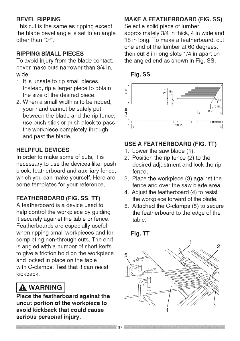
I WARNINGi
When width or rip narrower than
2 in. the push stick cannot be
used because the blade guard will
interfere. Use the auxiliary fence (4)
and push block (5) as shown.
Fig. RR
4
8. Continue pushing the workpiece (6)
with the push stick (3-Fig. QQ) or
push block until it passes through
the blade guard and clears the rear
of the table. (Fig. RR)
9. Never pull the piece back when the
blade is turning. Turn the switch
OFF. When the blade completely
stops, you can then remove the
workpiece.
i_ WARNING]
Never attempt to pull the workpiece
backwards during a cutting
operation. This will cause kickback
and serious injury to the user can
occur. When the blade completely
stops, raise the anti=kickback pawls
(7) on each side of the riving knife
and slide the workpiece out.
Fig. QQ 6
2 1
;* 36
BEVEL RIPPING
This cut is the same as ripping except
the blade bevel angle is set to an angle
other than "0°''.
RIPPING SMALL PIECES
To avoid injury from the blade contact,
never make cuts narrower than 3/4 in.
wide.
1. It is unsafe to rip small pieces.
Instead, rip a larger piece to obtain __]-
the size of the desired piece. 1
2. When a small width is to be ripped,
your hand cannot be safely put __
between the blade and the rip fence, _J_
i
use push stick or push block to pass -i-i,
the workpiece completely through
and past the blade.
HELPFUL DEVICES
In order to make some of cuts, it is
necessary to use the devices like, push
block, featherboard and auxiliary fence,
which you can make yourself. Here are
some templates for your reference.
FEATHERBOARD (FIG. SS, TT)
A featherboard is a device used to
help control the workpiece by guiding
it securely against the table or fence.
Featherboards are especially useful
when ripping small workpieces and for
completing non-through cuts. The end
is angled with a number of short kerfs
to give a friction hold on the workpiece
and locked in place on the table
with C-clamps. Test that it can resist
kickback.
[,_ WARNING ]
Place the featherboard against the
uncut portion of the workpiece to
avoid kickback that could cause
serious personal injury.
MAKE A FEATHERBOARD (FIG. SS)
Select a solid piece of lumber
approximately 3/4 in thick, 4 inwide and
18 in long. To make a featherboard, cut
one end of the lumber at 60 degrees,
then cut 8 in-long slots 1/4 in apart on
the angled end as shown in Fig. SS.
Fig. SS
.=--
r '
• J i , , , , , i iiiii]f_flfN
18in _'l
USE AFEATHERBOARD (FIG. TT)
1. Lower the saw blade (1).
2. Position the rip fence (2) to the
desired adjustment and lock the rip
fence.
3. Place the workpiece (3) against the
fence and over the saw blade area.
4. Adjust the featherboard (4) to resist
the workpiece forward of the blade.
5. Attached the C-clamps (5) to secure
the featherboard to the edge of the
table.
5
\
Fig. TT
3
4
37
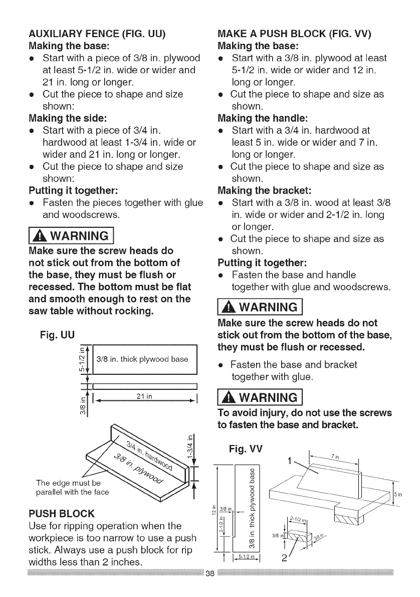
AUXILIARY FENCE (FIG. UU)
Making the base:
o Start with a piece of 3/8 in. plywood
at least 5-1/2 in. wide or wider and
21 in. long or longer.
o Cut the piece to shape and size
shown:
Making the side:
o Start with a piece of 3/4 in.
hardwood at least 1-3/4 in. wide or
wider and 21 in. long or longer.
o Cut the piece to shape and size
shown:
Putting it together:
o Fasten the pieces together with glue
and woodscrews.
i_ WARNING]
Make sure the screw heads do
not stick out from the bottom of
the base, they must be flush or
recessed. The bottom must be flat
and smooth enough to rest on the
saw table without rocking.
Fig. UU
3/8 in. thick plywood base
-'Tl I
The edge must be _I
parallel with l
PUSH BLOCK
Use for ripping operation when the
workpiece is too narrow to use a push
stick. Always use a push block for rip
widths less than 2 inches.
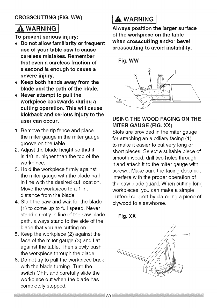
MAKE A PUSH BLOCK (FIG. VV)
Making the base:
o Start with a 3/8 in. plywood at least
5-1/2 in. wide or wider and 12 in.
long or longer.
o Cut the piece to shape and size as
shown.
Making the handle:
o Start with a 3/4 in. hardwood at
least 5 in. wide or wider and 7 in.
long or longer.
o Cut the piece to shape and size as
shown.
Making the bracket:
o Start with a 3/8 in. wood at least 3/8
in. wide or wider and 2-1/2 in. long
or longer.
o Cut the piece to shape and size as
shown.
Putting it together:
o Fasten the base and handle
together with glue and woodscrews.
l_, WARNING]
Make sure the screw heads do not
stick out from the bottom of the base,
they must be flush or recessed.
o Fasten the base and bracket
together with glue.
i_ WARNING]
To avoid injury, do not use the screws
to fasten the base and bracket.
Fig. VV
_1 II =-I
TV I
Ii_-_'2_°i
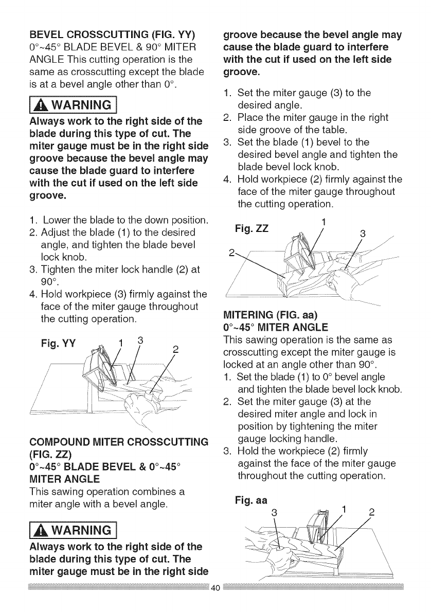
CROSSCUTTING (FIG. WW)
{_ WARNING]
To prevent serious injury:
o Do not allow familiarity or frequent
use of your table saw to cause
careless mistakes. Remember
that even a careless fraction of
a second is enough to cause a
severe injury.
o Keep both hands away from the
blade and the path of the blade.
o Never attempt to pull the
workpiece backwards during a
cutting operation. This will cause
kickback and serious injury to the
user can occur.
1. Remove the rip fence and place
the miter gauge in the miter gauge
groove on the table.
2. Adjust the blade height so that it
is 1/8 in. higher than the top of the
workpiece.
3. Hold the workpiece firmly against
the miter gauge with the blade path
in line with the desired cut location.
Move the workpiece to a 1 in.
distance from the blade.
4. Start the saw and wait for the blade
(1) to come up to full speed. Never
stand directly in line of the saw blade
path, always stand to the side of the
blade that you are cutting on.
5. Keep the workpiece (2) against the
face of the miter gauge (3) and flat
against the table. Then slowly push
the workpiece through the blade.
6. Do not try to pull the workpiece back
with the blade turning. Turn the
switch OFF, and carefully slide the
workpiece out when the blade has
completely stopped.
I WARNINGi
Always position the larger surface
of the workpiece on the table
when crosscutting and/or bevel
crosscutting to avoid instability.
Fig. WW
2
3 \ _/1
USING THE WOOD FACING ON THE
MITER GAUGE (FIG. XX)
Slots are provided in the miter gauge
for attaching an auxiliary facing (1)
to make it easier to cut very long or
short pieces. Select a suitable piece of
smooth wood, drill two holes through
it and attach it to the miter gauge with
screws. Make sure the facing does not
interfere with the proper operation of
the saw blade guard. When cutting long
workpieces, you can make a simple
outfeed support by clamping a piece of
plywood to a sawhorse.
Fig. XX
BEVELCROSSCUTTING(FIG.YY)
0°-45° BLADEBEVEL& 90° MITER
ANGLEThiscuttingoperationis the
same as crosscutting except the blade
is at a bevel angle other than 0°.
[_]_ WARNING]
Always work to the right side of the
blade during this type of cut. The
miter gauge must be in the right side
groove because the bevel angle may
cause the blade guard to interfere
with the cut if used on the left side
groove.
groove because the bevel angle may
cause the blade guard to interfere
with the cut if used on the left side
groove.
1. Set the miter gauge (3) to the
desired angle.
2. Place the miter gauge in the right
side groove of the table.
3. Set the blade (1) bevel to the
desired bevel angle and tighten the
blade bevel lock knob.
4. Hold workpiece (2) firmly against the
face of the miter gauge throughout
the cutting operation.
1. Lower the blade to the down position.
2. Adjust the blade (1) to the desired
angle, and tighten the blade bevel
lock knob.
3. Tighten the miter lock handle (2) at
90°"
4. Hold workpiece (3) firmly against the
face of the miter gauge throughout
the cutting operation.
Fig. YY 32
\
COMPOUND MITER CROSSCUTTING
(FIG.ZZ)
00~45 ° BLADE BEVEL &00~45 °
MITER ANGLE
This sawing operation combines a
miter angle with a bevel angle.
j,d_WARNING ]
Always work to the right side of the
blade during this type of cut. The
miter gauge must be in the right side
1
Fig. ZZ
MITERING (FIG. aa)
00~45° MITER ANGLE
This sawing operation is the same as
crosscutting except the miter gauge is
locked at an angle other than 90°.
1. Set the blade (1) to 0° bevel angle
and tighten the blade bevel lock knob.
2. Set the miter gauge (3) at the
desired miter angle and lock in
position by tightening the miter
gauge locking handle.
3. Hold the workpiece (2) firmly
against the face of the miter gauge
throughout the cutting operation.
Fig. aa
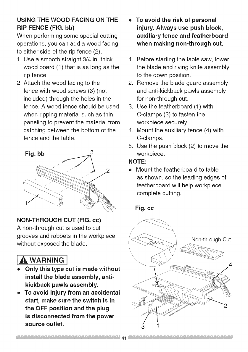
USINGTHEWOOD FACING ON THE
RiP FENCE (FIG. bb)
When performing some special cutting
operations, you can add a wood facing
to either side of the rip fence (2).
1. Use a smooth straight 3/4 in. thick
wood board (1) that is as long as the
rip fence.
2. Attach the wood facing to the
fence with wood screws (3) (not
included) through the holes in the
fence. A wood fence should be used
when ripping material such as thin
paneling to prevent the material from
catching between the bottom of the
fence and the table.
Fig. bb 3
NON=THROUGH CUT (FIG. cc)
A non-through cut is used to cut
grooves and rabbets in the workpiece
without exposed the blade.
i,A WARNING]
o Only this type cut is made without
install the blade assembly, anti-
kickback pawls assembly.
o To avoid injury from an accidental
start, make sure the switch is in
the OFF position and the plug
is disconnected from the power
source outlet.
To avoid the risk of personal
injury. Always use push block,
auxiliary fence and featherboard
when making non-through cut.
1. Before starting the table saw, lower
the blade and riving knife assembly
to the down position.
2. Remove the blade guard assembly
and anti-kickback pawls assembly
for non-through cut.
3. Use the featherboard (1) with
C-clamps (3) to fasten the
workpiece securely.
4. Mount the auxiliary fence (4) with
C-clamps.
5. Use the push block (2) to move the
workpiece.
NOTE:
o Mount the featherboard to table
as shown, so the leading edges of
featherboard will help workpiece
complete cutting.
Fig. cc
\
Non-through Cut
4
3 1
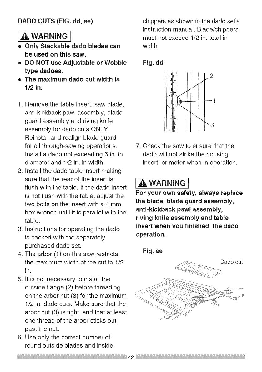
DADOCUTS(FIG. dd, ee)
1,,_,WARNING]
o Only Stackable dado blades can
be used on this saw.
o DO NOT use Adjustable or Wobble
type dadoes.
o The maximum dado cut width is
1/2 in.
1. Remove the table insert, saw blade,
anti-kickback pawl assembly, blade
guard assembly and riving knife
assembly for dado cuts ONLY.
Reinstall and realign blade guard
for all through-sawing operations.
Install a dado not exceeding 6 in. in
diameter and 1/2 in. in width
2. Install the dado table insert making
sure that the rear of the insert is
flush with the table. If the dado insert
is not flush with the table, adjust the
two bolts on the insert with a 4 mm
hex wrench until it is parallel with the
table.
3. Instructions for operating the dado
is packed with the separately
purchased dado set.
4. The arbor (1) on this saw restricts
the maximum width of the cut to 1/2
in.
5. It is not necessary to install the
outside flange (2) before threading
on the arbor nut (3) for the maximum
1/2 in. dado cuts. Make sure that the
arbor nut (3) is tight, and that at least
one thread of the arbor sticks out
past the nut.
6. Use only the correct number of
round outside blades and inside
chippers as shown in the dado set's
instruction manual. Blade/chippers
must not exceed 1/2 in. total in
width.
Fig. dd
2
7. Check the saw to ensure that the
dado will not strike the housing,
insert, or motor when in operation.
i.,_L.WARNING]
For your own safety, always replace
the blade, blade guard assembly,
anti=kickback pawl assembly,
riving knife assembly and table
insert when you finished the dado
operation.
Fig. ee
Dado cut
_2
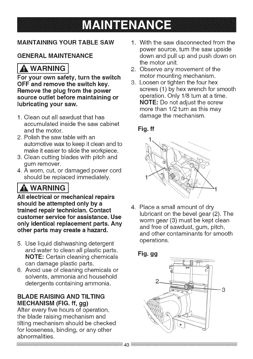
MAINTAINING YOUR TABLE SAW
GENERAL MAINTENANCE
{,,A WARNING]
For your own safety, turn the switch
OFF and remove the switch key.
Remove the plug from the power
source outlet before maintaining or
lubricating your saw.
1. Clean out all sawdust that has
accumulated inside the saw cabinet
and the motor.
2. Polish the saw table with an
automotive wax to keep it clean and to
make it easier to slide the workpiece.
3. Clean cutting blades with pitch and
gum remover.
4. A worn, cut, or damaged power cord
should be replaced immediately.
{,,_, WARNING]
All electrical or mechanical repairs
should be attempted only by a
trained repair technician. Contact
customer service for assistance. Use
only identical replacement parts. Any
other parts may create a hazard.
5. Use liquid dishwashing detergent
and water to clean all plastic parts.
NOTE: Certain cleaning chemicals
can damage plastic parts.
6. Avoid use of cleaning chemicals or
solvents, ammonia and household
detergents containing ammonia.
1. With the saw disconnected from the
power source, turn the saw upside
down and pull up and push down on
the motor unit.
2. Observe any movement of the
motor mounting mechanism.
3. Loosen or tighten the four hex
screws (1) by hex wrench for smooth
operation. Only 1/8 turn at a time.
NOTE: Do not adjust the screw
more than 1/2 turn as this may
damage the mechanism.
.
Fig. ff
1
Place a small amount of dry
lubricant on the bevel gear (2). The
worm gear (3) must be kept clean
and free of sawdust, gum, pitch,
and other contaminants for smooth
operations.
Fig. gg
BLADE RAISING AND TILTING
MECHANISM (FIG. ff, gg)
After every five hours of operation,
the blade raising mechanism and
tilting mechanism should be checked
for looseness, binding, or any other
abnormalities.
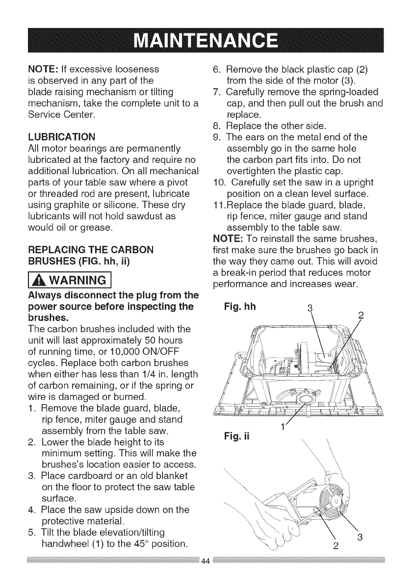
NOTE:Ifexcessivelooseness
isobservedinanypartofthe
bladeraisingmechanismortilting
mechanism,takethecompleteunitto a
ServiceCenter.
LUBRICATION
Allmotorbearingsarepermanently
lubricatedatthefactoryandrequireno
additionallubrication.Onallmechanical
partsofyourtablesawwhereapivot
orthreadedrodarepresent,lubricate
usinggraphiteorsilicone.Thesedry
lubricantswillnotholdsawdustas
wouldoilorgrease.
REPLACINGTHECARBON
BRUSHES(FIG. hh, ii)
[_)_ WARNING]
Always disconnect the plug from the
power source before inspecting the
brushes.
The carbon brushes included with the
unit will last approximately 50 hours
of running time, or 10,000 ON/OFF
cycles. Replace both carbon brushes
when either has less than 1/4 in. length
of carbon remaining, or if the spring or
wire is damaged or burned.
1. Remove the blade guard, blade,
rip fence, miter gauge and stand
assembly from the table saw.
2. Lower the blade height to its
minimum setting. This will make the
brushes's location easier to access.
3. Place cardboard or an old blanket
on the floor to protect the saw table
surface.
4. Place the saw upside down on the
protective material.
5. Tilt the blade elevation/tilting
handwheel (1) to the 45 ° position.
6. Remove the black plastic cap (2)
from the side of the motor (3).
7. Carefully remove the spring-loaded
cap, and then pull out the brush and
replace.
8. Replace the other side.
9. The ears on the metal end of the
assembly go in the same hole
the carbon part fits into. Do not
overtighten the plastic cap.
10. Carefully set the saw in a upright
position on a clean level surface.
11.Replace the blade guard, blade,
rip fence, miter gauge and stand
assembly to the table saw.
NOTE: To reinstall the same brushes,
first make sure the brushes go back in
the way they came out. This will avoid
a break-in period that reduces motor
performance and increases wear.
Fig. hh 3
Fig. ii
\\\\\
\\\
\ 3
2
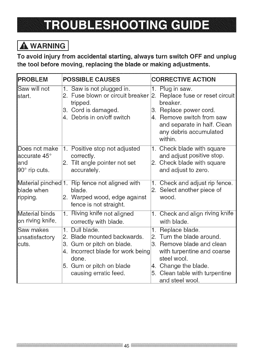
i,A WARNING ]
To avoid injury from accidental starting, always turn switch OFF and unplug
the tool before moving, replacing the blade or making adjustments.
PROBLEM
Saw will not
start.
Does not make 1.
accurate 45°
and 2.
90° rip cuts.
Material pinched 1.
blade when
ripping. 2.
Material binds 1.
on riving knife.
Saw makes 1.
unsatisfactory 2.
cuts. 3.
4.
5.
POSSIBLE CAUSES CORRECTIVE ACTION
1. Saw is not plugged in.
2. Fuse blown or circuit breaker
tripped.
3. Cord is damaged.
4. Debris in on/off switch
Positive stop not adjusted
correctly.
Tilt angle pointer not set
accurately.
Rip fence not aligned with
blade.
Warped wood, edge against
fence is not straight.
Riving knife not aligned
correctly with blade.
Dull blade.
Blade mounted backwards.
Gum or pitch on blade.
Incorrect blade for work being
done.
Gum or pitch on blade
causing erratic feed.
1. Plug in saw.
2. Replace fuse or reset circuit
breaker.
3. Replace power cord.
4. Remove switch from saw
and separate in half. Clean
any debris accumulated
within.
1. Check blade with square
and adjust positive stop.
2. Check blade with square
and adjust to zero.
1. Check and adjust rip fence.
2. Select another piece of
wood.
1. Check and align riving knife
with blade.
1. Replace blade.
2. Turn the blade around.
3. Remove blade and clean
with turpentine and coarse
steel wool.
4. Change the blade.
5. Clean table with turpentine
and steel wool.
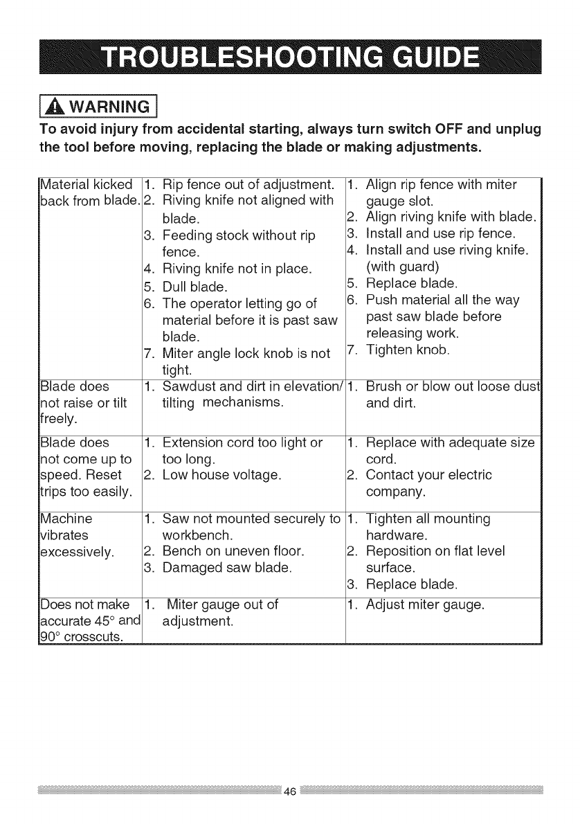
1,_ WARNING ]
To avoid injury from accidental starting, always turn switch OFF and unplug
the tool before moving, replacing the blade or making adjustments.
Material kicked
back from blade. 1. Rip fence out of adjustment.
2. Riving knife not aligned with
blade.
3. Feeding stock without rip
fence.
4. Riving knife not in place.
5. Dull blade.
6. The operator letting go of
material before it is past saw
blade.
1. Align rip fence with miter
gauge slot.
2. Align riving knife with blade.
3. Install and use rip fence.
4. Install and use riving knife.
(with guard)
5. Replace blade.
6. Push material all the way
past saw blade before
releasing work.
Blade does
not raise or tilt
freely.
Blade does 1.
not come up to
speed. Reset 2.
trips too easily.
Machine 1.
vibrates
excessively. 2.
3.
Does not make 1.
accurate 45° and
90° crosscuts.
7. Miter angle lock knob is not
tight.
1. Sawdust and dirt in elevation/
tilting mechanisms.
Extension cord too light or
too long.
Low house voltage.
Saw not mounted securely to
workbench.
Bench on uneven floor.
Damaged saw blade.
Miter gauge out of
adjustment.
7. Tighten knob.
1. Brush or blow out loose dust
and dirt.
1. Replace with adequate size
cord.
2. Contact your electric
company.
1. Tighten all mounting
hardware.
2. Reposition on flat level
surface.
3. Replace blade.
1. Adjust miter gauge.
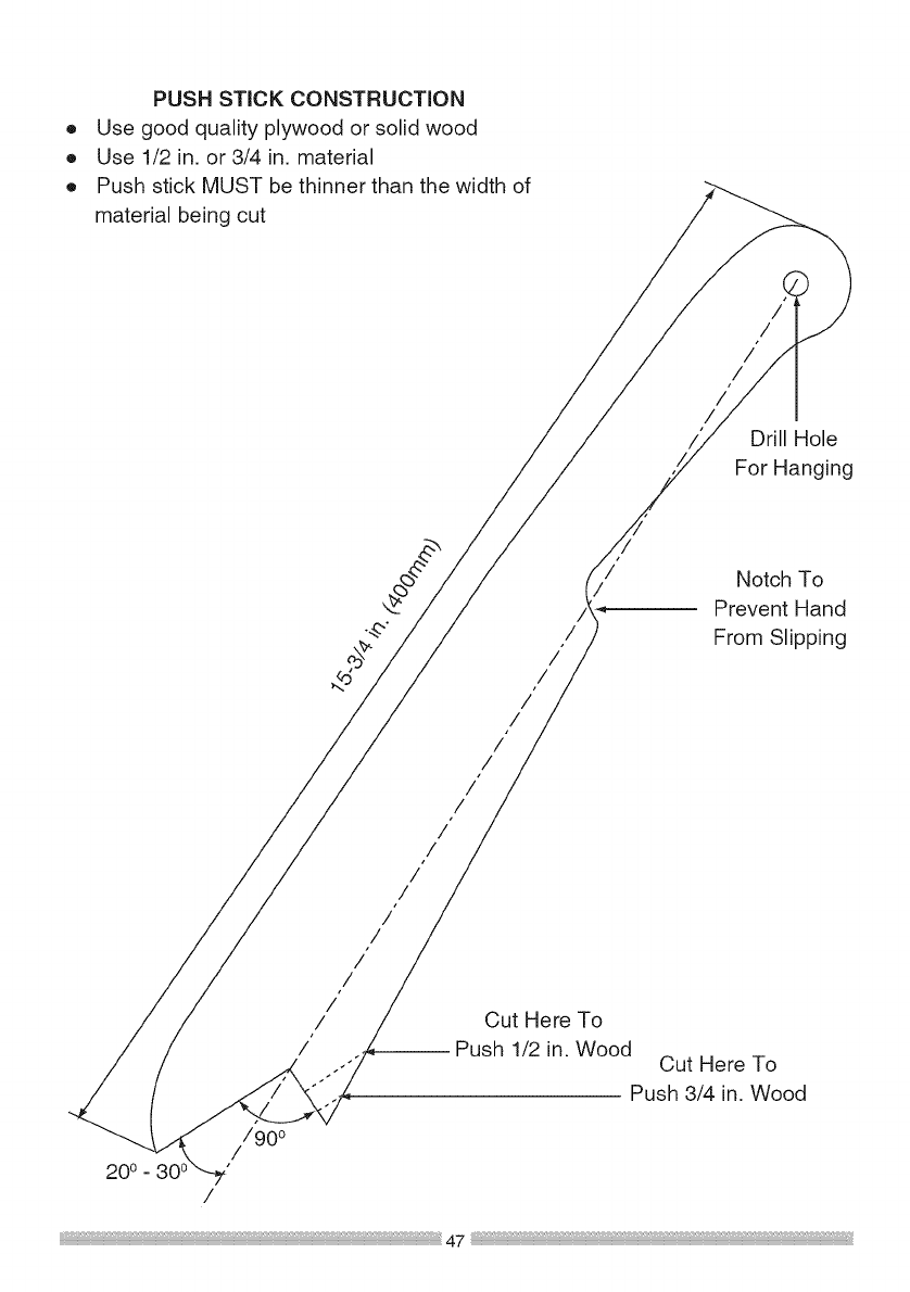
®
®
®
PUSH STICK CONSTRUCTION
Use good quality plywood or solid wood
Use 1/2 in. or 3/4 in. material
Push stick MUST be thinner than the width of
material being cut
/
/
/
/
/
/Drill Hole
For Hanging
/
/
/
/
/
/
/
/
/
/
/"
/
/
/
/
/"
/
/
/
Notch To
Prevent Hand
From Slipping
Cut Here To
-- Push 1/2 in. Wood Cut Here To
Push 3/4 in. Wood
//900
200 -
/

10 in. TABLE SAW MODEL NO. 137.218070
i_ WARNING ]
When servicing use only CRAFTSMAN replacement parts. Use of any other
parts many create a HAZARD or cause product damage. Any attempt to
repair or replace electrical parts on this Table Saw may create aHAZARD
unless repair is done by aqualified service technician. Repair service is
available at your nearest Sears Service Center.
PARTS LiST FOR TABLE SAW SCHEMATIC A
Description Size QTY
CLAMP HANDLE M6_1.0 1
FLAT WASHER cp5_10-0 3 10
FLAT WASHER 3/163/8 0022 8
FLAT WASHER 1/4"3/4-1/16 2
FLAT WASHER 1/4_1/2-3/32 1
EXTERNAL TOOTH LOCK WASHER @5 1
HEX SOC. HD. CAP BOLT M6_1.0-16 1
CR. RE. TRUSS HD. SCREW M4_0.7-10 2
CR. RE. ROUND WASHER HD. SCREW M5_0.8-6 1
I.D,
0B6V
0J5L
0J6V
0J76
0J78
0JAF
0JVY
0K6Y
0K7E
0K9T
0K9U
0KAE
0KBA
0KBQ
0KCX
0KCY
0SZY
0SZZ
10K5
10LB
10LE
212M
25AP
26LU
275F
28N2
290M
29R2
29WT
2AZ7
2DUB
2EUO
2EVJ
2FSV
I.D. Description
2FTB EXTENSION WiNG (LEFT)
2GYV SLiDiNG BASE ASS'Y
2JHQ SLiDiNG BASE ASS'Y
2NE3 NEEDLE POINTER
2NE4 NEEDLE POINTER
2NRD EXTENSION WiNG ROD
2NRE EXTENSION WiNG ROD
2NRF EXTENSION WiNG ROD
2NRG EXTENSION WiNG ROD
HEX HD. TAPPING SCREW M5_16-16
HEX, HD. TAPPING SCREW M5_16-25
CR. RE. PAN HD. TAPPING SCREW M5_0.8-10
CR. RE. PAN HD. TAPPING SCREW M5_16-12
CR. RE. PAN HD. TAPPING SCREW M5_16-10
CR. RE. PAN HD PLAIN WASHER M5_0.8_10
TAPPING SCREW
CR. RE. PAN HD PLAIN WASHER M5_0.8_12
TAPPING SCREW
SLiDiNG BASE ASS'Y
SLiDiNG BASE ASS'Y
HEX SOC. HD CAP BOLT M5_0.8-8
BOLT CLAMP
CR. RE. TRUSS HD. ROUND NECK M5_0.8-16
SCREW
LEAD WIRE ASS'Y
HEX, SOC. HD, CAP BOLT M6_1.0-25
WARNING LABEL
LOCATION SEAT
AAA BATTERY
CAUTION LABEL
WARNING LABEL
LASER SETASS'Y
CR. RE PAN HD PLAIN WASHER M2.6_24_8
TAPPING SCREW
CR. RE, ROUND WASHER HD. SCREW M5_0.8-12 3
TiLTiNG SCALE 2
MITER GAUGE ASS'Y 1
TABLE #AW 1
2 2NSC
8 2RV8
3 2RVE
4 2RVP
1 2RVQ
4 2RVX
8 2RW4
1 2RW6
1 2RWG
4 2RXQ
1 2RXS
3 2SUU
1 2SUV
1 2SUW
1 2SUX
2 2SUY
2 2SV2
1 2SUS
2 2T6B
1 2T6C
1 2T6D
2T6F
2T87
2TB9
REAR OUT-FEED SUPPORT ROD
REAR OUT-FEED SUPPORT
iNSERT
BETPLATE
RiViNG KNIFE
BLADE GUARD
NEEDLE POINTER
BETPLATE
EXTENTION WiNG (RIGHT)
SPACER
RIP FENCE ASS'Y
SCALE(RIGHT)
SCALE (LEFT)
SCALE (LEFT)
SCALE(RIGHT)
SCALE
WARNING LABEL
INSTRUCTIONS MANUAL
HARDWARE BAG ASS'Y
BLADE GUARD ASS'Y
ANTPKICKBACK PAWL ASS'Y
HANDLE
LABEL(LASER)-LEFT
LABEL(LASER)-RIGHT
Size QTY
#AW 1
2
2
2
#23
1
#AW 1
2
1
1
1
2
1
1
48
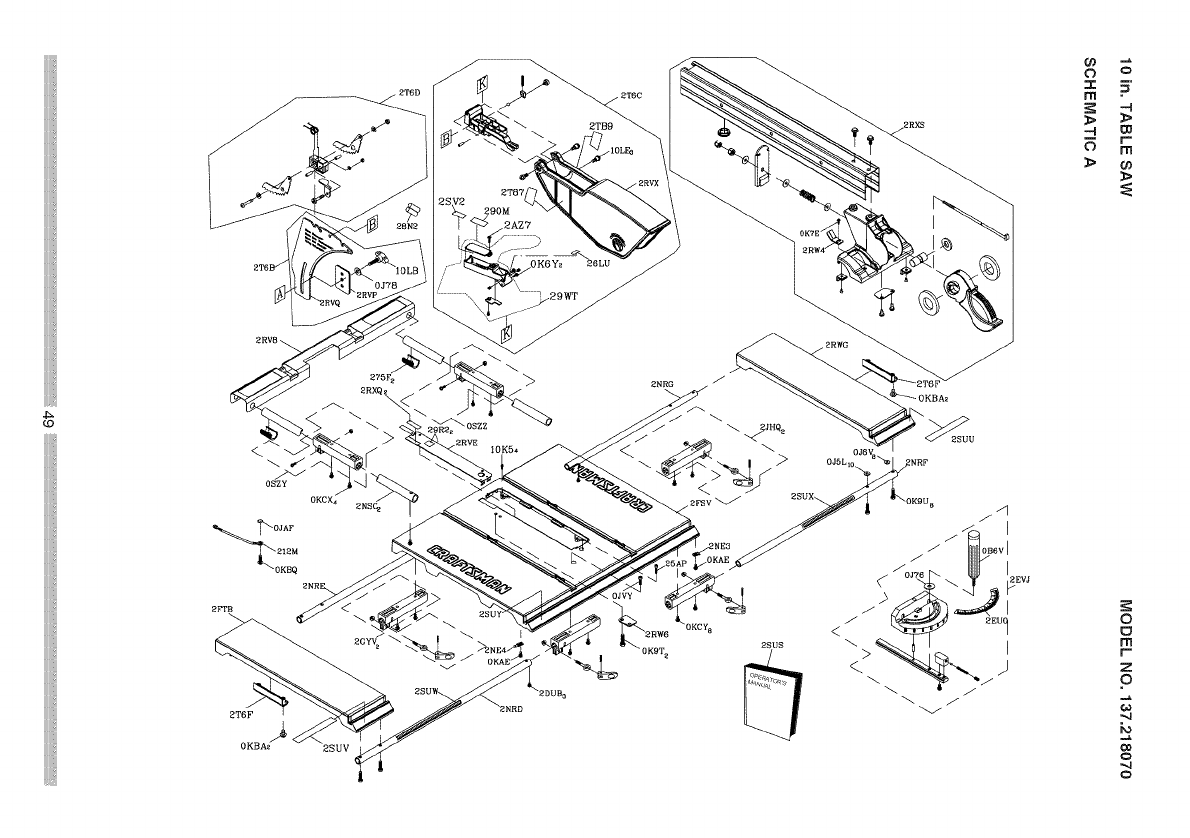
2TB9
]
0 o
I 5'
m
> >
r
m
>
02J A F
12M
_0KBQ
OKCX4
10K54
2SUS
o
m
r-
z
o
'-4
co
o
.,4
o

10 in. TABLE SAW MODEL NO. 137.218070
PARTS LiST FOR SAW SCHEMATIC B
I.D. Description Size
0901 BUSH
08VH CORD CLAMP
08VN POINTER BRACKET
090Q PLUNGER HOUSING
09JK WRENCH
0AW8 SEGMENT GEAR
0B3R WRENCH
0B9P CLAMP
0BA1 COMPRESSION SPRING
0BA4 SPACER
0BA9 SPACER
0BAC SET NUT
0BAE ARBOR COLLAR
0BPA LOCK KNOB
0J3P HEX. WRENCH
0J4F FLAT WASHER cp8_16-2.5
0J5C FLAT WASHER @13.8_10-2.85
0J6K FLAT WASHER cp6_30-4
0J6T FLAT WASHER 3/16_3/4-1/16
0J70 FLAT WASHER 1/4_3/4-7/64
0J74 FLAT WASHER 1/4_5/8-3/32
0J77 FLAT WASHER 1/4_9/16-3/64
0J8D FLAT WASHER 3/8_3/4-5/64
0JAE EXTERNAL TOOTH LOCK WASHER @4
0JAF EXTERNAL TOOTH LOCK WASHER @5
0JB2 WAVE WASHER WW-12
0JC9 SPRING PIN
0JD1 SPRING PIN
0JPJ HEX, HD. BOLT M6_1.0-40
0JZY HEX, SOC. TRUSS HD. SCREW M6_1.0-12
0KOY HEX, HD. SCREW AND WASHER M6_1.0-20
0K1G HEX. HD. SCREW AND WASHER M6_1.0-12
0K45 CR. RE. PAN HD. SCREW & M6_1,0-12
WASHER
0K8C CR. RE. COUNT HD. TAPPING M4_18_10
SCREW
0K9T HEX. HD. TAPPING SCREW M5_16-16
0K9U HEX. HD. TAPPING SCREW M5_16-25
0KA4 CR. RE. PAN HD. TAPPING SCREW M4_16-16
0KCA CR. RE. TRUSS HD. TAPPING M5_12-12
SCREW
0KDK CR. RE. PAN HD. SCREW M5_0.8-16
0KF7 CR. RE. PAN HD. SCREW M4_0.7-12
0KJ7 CAP HD. SQ.NECK BOLT M8_1.25-16
0KMY HEX. NUT M8_1.25 T=6.5
0KNE HEX. NUT M6_1.0 T=5
0KQW LOCK NUT M5_0.8 T=5
0KQX NUT M6_1.0 T=6
0KQY LOCK NUT M8_1.25 T=8
QTY
4
11
6
4
2
2
1
2
1
1
2
2
1
1
I.D. Description
OKSM STRAIN RELIEF
OKTH STRAIN RELIEF
OKUX TERMINAL
OKWU LEAD WIRE ASS'Y
OLSL CIRCUIT BREAKER SWITCH
OLVJ SWITCH KEY
OLWG ON/OFF ROCKER SWITCH ASSEMBLY
OSGC HANDLE BAR
10J9 CAP HD. SQ. NECK BOLT
2149 KNOB
23PP BLADE
26E8 FLAT WASHER
275R LOCATION SEAT
27JR HEX. SOC. SET SCREW
29R6 STICKER
2A47 HEX. HD. SCREW AND WASHER
2A48 HEX. HD. SCREW AND WASHER
2BUY BODY SHELL
2CBS PUSH BLOCK
2EJX POWER CABLE ASS'Y
2RVH WHEEL
2RVJ CLAMPER BRACKET
2RVK BODY
2RVM GEAR
2RVN SPLITTERBRACKET
2RVR GUIDE CLAMP
2RVW RETAINING CLIP
2RW3 RETAINING CLIP
2RW5 NEEDLE POINTER
2RW8 SHIM
2RWA ANGLE ROD
2RWC HEIGHT REGULATING BOLT
2S15 MOTOR ASS'Y
2SEO ANCHOR PLATE
2SE9 SAFETY PLATE
2SJU SPACER
2SUZ WARNING LABEL
2SV1 LABEL
2SV3 LABEL
2T69 SPECIAL BOLT
2T6E CLAMP ASS'Y
2TD0 COLLAR
2TDD WORM
2TDL FLAT WASHER
2TDS SWITCH BOX ASS'Y
Size
M6_1.0-40
cp5_9.5-1.2
M5_0.8-6
M6_1.0-12
M5_0.8 -16
QTY
1
2
4
1
2
6
4
2
2
1
1
1
1
1
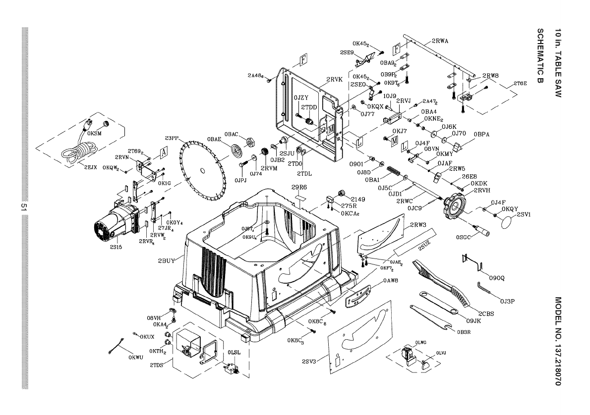
2RVR4
2815
08VH/_
OKA4_
_0KUX
0KTH 2
0KWU 2TDS_
2TDL
29R6
OJ6K
/OK J7
\"_ _O_o_v_
09018D_OJ OJAF
OBPA
26E8
)J4F
OB3R
o
o
m
ff-
z
o
"q
Co
O
_4
O
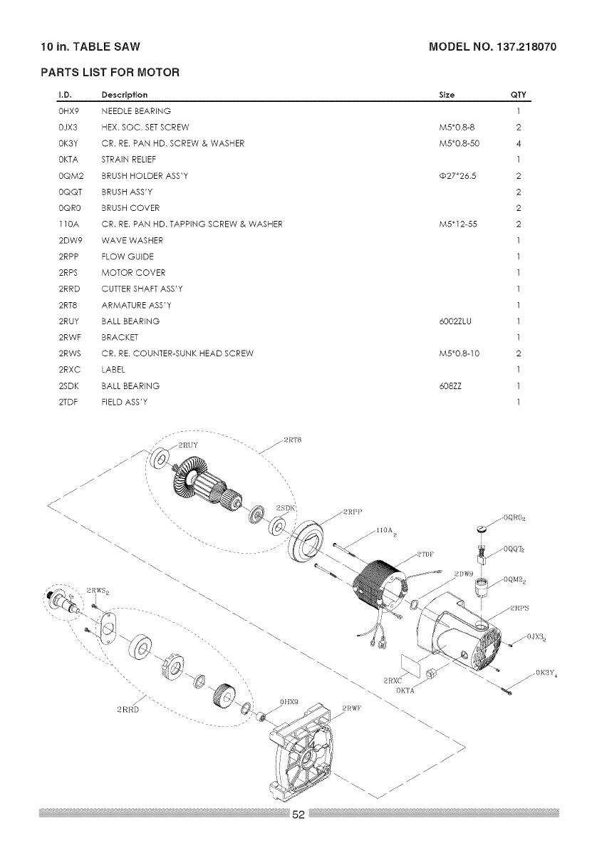
10 in. TABLE SAW MODEL NO, 137.218070
PARTS LiST FOR MOTOR
I.D. Description Size
OHX9 NEEDLE BEARLNG
OJX3 HEX. SOC. SETSCREW M5"0.8-8
OK3Y CR. RE. PAN HD. SCREW & WASHER M5"0.8-50
OKTA STRAIN RELIEF
OQM2 BRUSH HOLDER ASS'Y @27"26,5
OQQT BRUSH ASS'Y
OQR0 BRUSH COVER
110A CR. RE. PAN HD. TAPPING SCREW & WASHER M5"12-55
2DW9 WAVE WASHER
2RPP FLOW GULDE
2RPS MOTOR COVER
2RRD CUTTER SHAFT ASS'Y
2RT8 ARMATURE ASS'Y
2RUY BALL BEARLNG 6002ZLU
2RWF BRACKET
2RWS CR. RE. COUNTER-SUNK HEAD SCREW M5"0.8-10
2RXC LABEL
2SDK BALL BEARLNG 608ZZ
2TDF FIELD ASS'Y
QTY
1
2
4
1
2
2
2
2
1
1
1
2
1
1
1
zf
J
J
J
%..
\
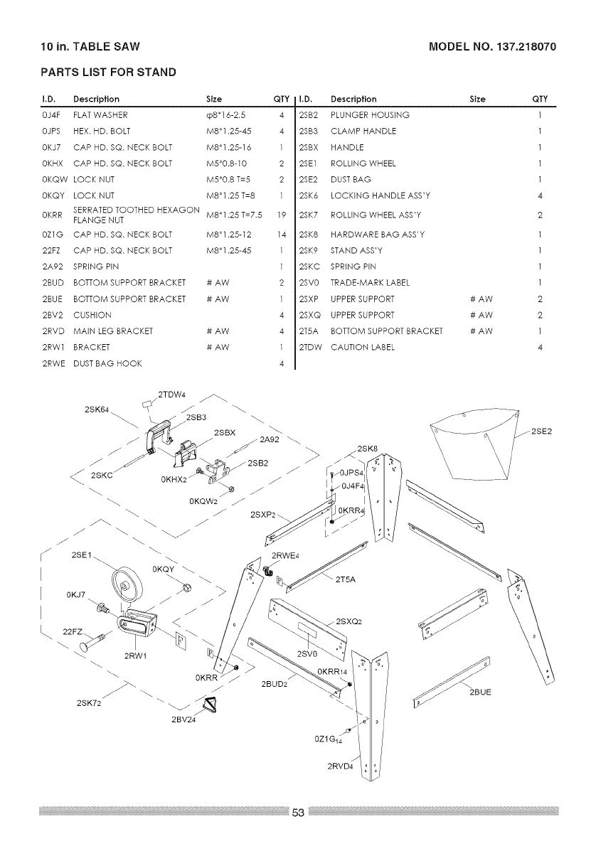
10 in. TABLE SAW
PARTS LiST FOR STAND
MODEL NO. 137.218070
I.D, Description Size QTY
0J4F FLAT WASHER @8_16-2.5 4
0JPS HEX. HD. BOLT M8_1.25-45 4
0KJ7 CAP HD. SQ. FLECK BOLT M8_1.25-16 1
0KHX CAP HD. SQ. NECK BOLT M5_0.8-10 2
0KQW LOCK NUT M5_0.8 T=5 2
0KQY LOCK NUT M8_1.25 T=8 1
SERRATED TOOTHED HEXAGON
0KRR M8 _1.25 T=7.5 19
FLANGE NUT
0Z1G CAP HD. SQ. NECK BOLT M8_1.25-12 14
22FZ CAP HD. SQ. NECK BOLT M8_1.25-45 1
2A92 SPRING PIN 1
2BUD BOTTOM SUPPORT BRACKET # AW 2
2BUE BOTTOM SUPPORT BRACKET # AW 1
2BV2 CUSHION 4
2RVD MAIN LEG BRACKET # AW 4
2RW1 BRACKET # AW 1
2RWE DUST BAG HOOK 4
I.D. Description Size
2SB2 PLUNGER HOUSING
2SB3 CLAMP HANDLE
2SBX HANDLE
2SE1 ROLLING WHEEL
2SE2 DUST BAG
2SK6 LOCKING HANDLE ASS'Y
2SK7 ROLLING WHEEL ASS'Y
2SK8 HARDWARE BAG ASS'Y
2SK9 STAND ASS'Y
2SKC SPRING PIN
2SV0 TRADE-MARK LABEL
2SXP UPPER SUPPORT # AW
2SXQ UPPER SUPPORT # AW
2T5A BOTTOM SUPPORT BRACKET # AW
2TDW CAUTION LABEL
QTY
4
2
2
2
1
4
2RVD4
_2SE2


Your Home
For expert troubleshooting and home solutions advice:
www.managemyhome.com
For repair - in your home - of all major brand appliances,
lawn and garden equipment, or heating and cooling systems,
no matter who made it, no matter who sold it!
For the replacement parts, accessories and
owner's manuals that you need to do-it-yourself.
For Sears professional installation of home appliances
and items like garage door openers and water heaters.
1-800-4-MY-HOME ® (1-800-469-4663)
Call anytime, day or night (U.S.A. and Canada)
www.sears,oom www.sears,ca
Our Home
For repair of carry-in items like vacuums, lawn equipment,
and electronics, call anytime for the location of your nearest i
Sears Parts & Repair Service Center
1-800-488-1222 (u.s.A.) 1-800-469-4663 (Canada) !_!i
www,sears.com www,sears,ca
TO purchase a protection agreement on a product serviced by Sears:
1-800-827-6655 (U.S.A.) 1-800-361-6665 (Canada) I
Para pedir servicio de reparacion Au Canada pour service en frangais:
a domicitio, y para ordenar piezas: 1 800 LE FOYER Mc
1-888-SU-HOGAR® (1-800-,33-6937/
(1-888- 784- 6427) www. sea rs. ca
TM M
® Registered Trademark /Trademark /s Service Mark of Sears Brands, LLC
TM M
® Marca Registrada /Marca de F&brica /s Marca de Servicio de Sears Brands, LLC
MO MD
Marque de commerce /Marque deposee de Sears Brands, LLC © Sears Brands, LLC
