Craftsman 137221960 User Manual TABLE SAW Manuals And Guides L0910463
CRAFTSMAN Saw Table Manual L0910463 CRAFTSMAN Saw Table Owner's Manual, CRAFTSMAN Saw Table installation guides
User Manual: Craftsman 137221960 137221960 CRAFTSMAN TABLE SAW - Manuals and Guides View the owners manual for your CRAFTSMAN TABLE SAW #137221960. Home:Tool Parts:Craftsman Parts:Craftsman TABLE SAW Manual
Open the PDF directly: View PDF ![]() .
.
Page Count: 56
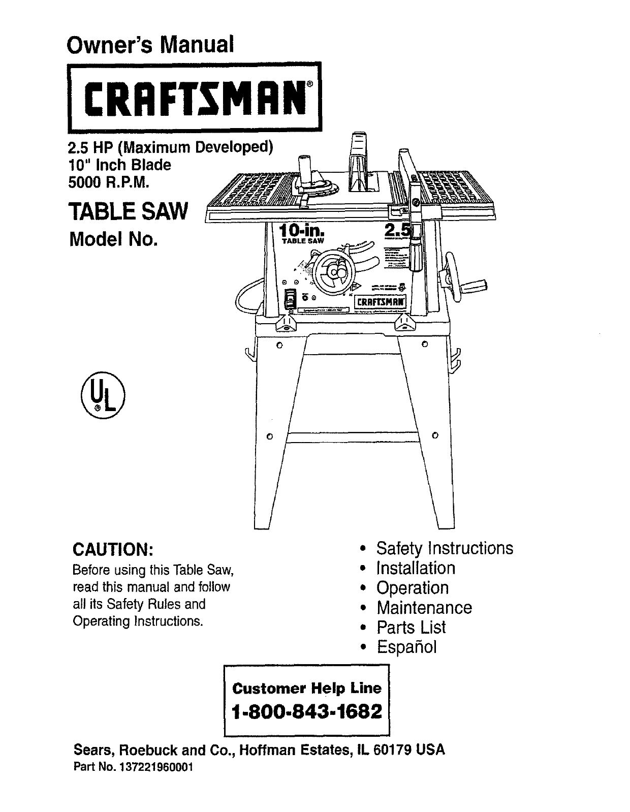
Owner's Manual
"l
ICRFIFTSMRN°,,
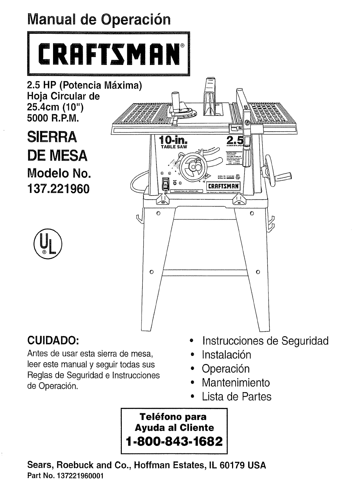
2.5 HP (Maximum Developed)
10" Inch Blade
5000 R.P.M.
TABLESAW ,
Model No. lO.in.
CAUTION: Safety Instructions
Before using this Table Saw, Installation
read this manual and follow Operation
all its Safety Rules and Maintenance
Operating Instructions. Parts List
EspaSol
Iosomo.e ..I
1-800-843-1682
Sears, Roebuck and Co., Hoffman Estates, IL 60179 USA
Part No. 137221960001
SECTION PAGE
Warranty ................................................................ 2
Product Specifications ..................................................... 2
Safety instructions ........................................................ 3
Accessories and Attachments ............................................... 6
Tools needed for assembly ................................................. 6
Carton Contents .......................................................... 6
Know Your Table Saw ...................................................... 8
Assembly and Adjustments ................................................. 9
Operation .............................................................. 16
Maintenance ............................................................ 20
Troubleshooting guide .................................................... 21
Parts .................................................................. 22
Making a push stick ...................................................... 26
EspaSol ................................................................ 29
FULL ONE YEAR WARRANTY
If this product fails due to a defect in materia) or workmanship within one year from the date of purchase, Sears
will repair it free of charge.
Contact a Sears Service Center for repair
If this product is used for commercial or rental purposes, this warranty applies only for 90 days from the date of
purchase.
This warranty gives you specific legal rights, and you may also have other rights which vary from state to state
Sears, Roebuck and Co., Dept. 817 WA, Hoffman Estates, IL 60179
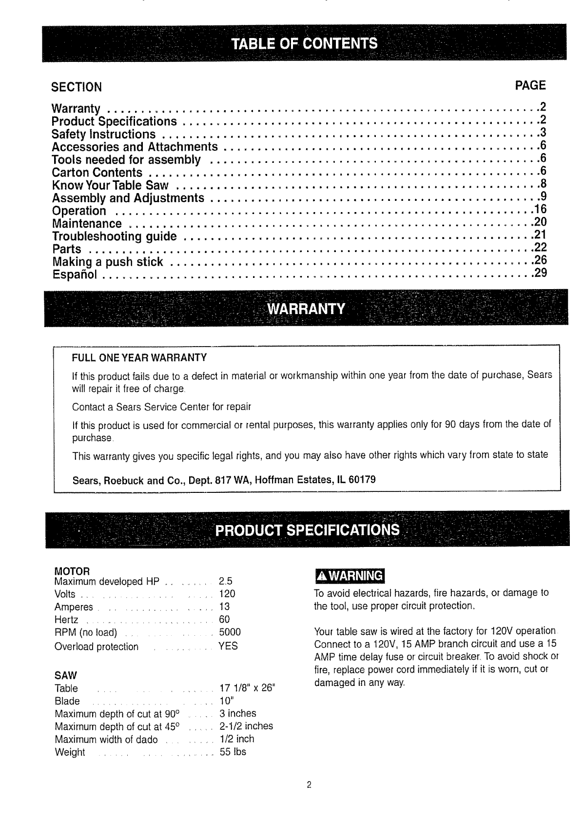
MOTOR
Maximum developed HP ....... 2,5
Volts ....................... 120
Amperes ................. 13
Hertz ......................... 60
RPM (no toad) .............. 5000
Overload protection ........... YES
SAW
Table ............. 17 t/8" x 26"
Blade .................. t0"
Maximum depth of cut at 90° ...... 3 inches
Maximum depth of cut at 45o ..... 2-1/2 inches
Maximum width of dado ........ 1/2 inch
Weight ................. 55 lbs
To avoid electrical hazards, fire hazards, or damage to
the tool, use proper circuit protection.
Your table saw is wired at the factory for 120V operation
Connect to a I20V, 15 AMP branch circuit and use a 15
AMP time delay fuse or circuit breaker, To avoid shock or
fire, replace power cord immediately if it is worn, cut or
damaged in any way..
GENERAL SAFETY INSTRUCTIONS
BEFORE USING THE TABLE SAW
Safety is a combination of common sense, staying alert
and knowing how to use your table saw
To avoid mistakes that could cause serious injury, do not
plug the table saw in until you have read and understood
the foltov_ing:
.
3
,
READ and become familiar with this entire instruction
manual LEARN the tool's applications, limitations, and
possible hazards
KEEP GUARDS IN PLACE and in working order
REMOVE ADJUSTING KEYS AND WRENCHES.
Form the habit of checking to see that keys and
adjusting wrenches are removed from the too! before
turning ON.
KEEP WORK AREA CLEAN. Cluttered areas and
benches invite accident&
.
DON'T USE IN A DANGEROUS ENVIRONMENT.
Don't use power tools in damp or wet locations, or
expose them to rain Keep work area well lighted
KEEP CHILDREN AWAY. All visitors should be kept at
a safe distance from the work area
7MAKE WORKSHOP KID PROOF with padlocks, master
switches, or by removing starter keys
8. DON'T FORCE THE TOOL. It will do the job better
and safer at the rate for which it was designed
9 USETHE RIGHTTOOL, Don't force tool or the
attachment to do a job for which it was not designed
I0 USE PROPER EXTENSION CORD. Make sure your
extension cord is in good condition When using an
extension cord, be sure to use one heavy enough to
carry the current your product will draw° An undersized
cord will cause a drop in line voltage resulting in loss
of power and overheating, The table on page 5 shows
the correct size to use depending on cord length and
nameplate ampere rating If in doubt, use the next
heavier gauge The smaller the gauge number, the
heavier the cord
11 WEAR PROPER APPAREL. DO NOT wear loose
clothing, gloves, neckties, rings, bracelets, or other
jewelry which may get caught in moving parts
Nonslip footwear is recommended. Wear protective
hair covering to contain long hair
12
13
14
!5
t6
17
18
19
20,,
21
22
WEARYOUn ALWAYS WEAR EYE
PROTECTION. Any table
saw can throw foreign
objects into the eyes which
could cause permanent eye
damage ALWAYS wear
Safety Goggles (not glasses)
that comply with ANSI safety standard Z87 1
Everyday eyeglasses have only impact-resistant
lenses They ARE NOT safety glasses Safety
Goggles are available at Sears NOTE: Glasses or
goggles not in compliance with ANSI 7_.87.1could
seriously hurt you when they break
WEAR A FACE MASK OR DUST MASK°
Sawing operation produces dust,
SECURE WORK. Use clamps or a vise to hold work
when practical. It's safer than using your hand and it
frees both hands to operate toot.
DISCONNECT TOOLS before servicing, and when
changing accessories, such as blades, bits, cutters,
and the like
REDUCE THE RISK OF UNINTENTIONAL STARTING.
Make sure the switch is in OFF position before
plugging in.,
USE RECOMMENDED ACCESSORIES. Consult the
owner's manual for the recommended accessories
The use of improper accessories may cause risk of
injury to persons
NEVER STAND ON TOOL. Serious injurycould occur
if the tool is tipped or if the cutting tool is unintentionally
contacted
CHECK FOR DAMAGED PARTS. Before further use of
the tool, a guard or other part that is damaged should
be carefully checked to determine that it will operate
properly and perform its intended function Check for
alignment of moving parts, binding of moving parts,
breakage of parts, mounting, and any other conditions
that may affect its operation A guard or other part that
is damaged should be properly repaired or replaced.
NEVER LEAVE TOOL RUNNING UNATI'ENDED.
TURN THE POWER OFF. Don't leave the tool until
it comes to a complete stop
DON'T OVERREACH. Keep proper footing and
balance at all times
MAINTAIN TOOLS WITH CARE, Keep tools sharp
and clean for best and safest performance. Follow
instructions for lubricating and changing accessories.
SAVE THESE INSTRUCTIONS

23. DIRECTION OF FEED, Feed work into a blade or cutter
against the direction of rotation of the blade or cutter
only
24. WARNING: Dust generated from certain materials can
be injurious to your health. Always operate saw in welt
ventilated areas and provide for proper dust removal.
SPECIFIC SAFETY INSTRUCTIONS
FORTHE TABLE SAW
1. ALWAYS USE SAW BLADE GUARD spreader and
anti-kickback pawls for every operation for which
they can be used, including through-sawing
Through-sawing operations are those in which the
blade cuts completely through the workpiece
when ripping or cross-cutting.
2. ALWAYS HOLD THE WORK FIRMLY against the
miter gauge or rip fence.
,
4_
5
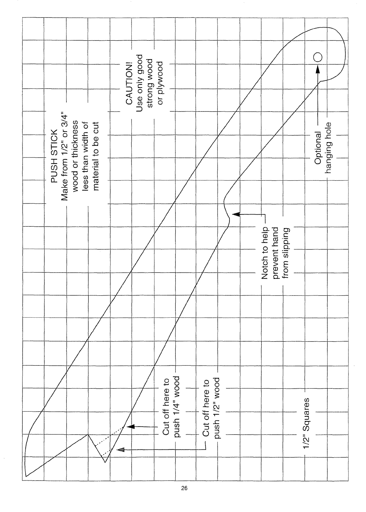
USE A PUSH STICK when required Always use a
push stick for ripping narrow stock Refer to ripping
applications in the instruction manual where the
push stick is covered in detail. See the push stick
pattern included in this Owner's Manual
NEVER PERFORM ANY OPERATION
"FREE HAND", which means using your hands
only to support or guide the workpiece. Always
use either the fence or-the miter gauge to position
and guide the work.
NEVER STAND or have any part of your body
in line with the path of the saw blade. Keep your
hands out of the line of the saw blade_
6. NEVER REACH behind or' over the cutting toot
for any reason.
7. REMOVE the rip fence when cross-cutting
8. DO NOT USE molding head set with this saw
9 FEED WORK INTOTHE BLADE against the
direction of rotation only.
10. NEVER use the fence as a cut-off gauge when
cross-cutting.
11. NEVER ATTEMPT TO FREE A STALLED SAW
BLADE without first turning the saw OFE Turn
power switch OFF immediately to prevent motor
damage..
t2,
13
14
PROVIDE ADEQUATE SUPPORT to the rear and
sides of the saw table for wide or long workpieces,
AVOID KICKBACKS (work thrown back towards
you) by keeping the blade sharp, keeping the rip
fence parallel to the saw blade, and by keeping the
spreader, anti-kickback pawls, and guard in place
and functioning Do not release work before it is
pushed all the way past the saw blade. Do not rip
work that is twisted, warped, or does not have a
straight edge to guide along the fence
AVOID AWKWARD OPERATIONS and hand
positions where a sudden slip could cause your
hand to move into the cutting tool.
t5 NEVER USE SOLVENTS to clean plastic parts.
Solvents could possibly dissolve or otherwise
damage the material Only a soft damp cloth should
be used to clean plastic parts
16.
17.
MOUNT your table saw before performing any
cutting operations. Refer to installation instructions
NEVER CUT METALS or materials which may make
hazardous dust
t8_ ALWAYS USE IN A WELL VENTILATED AREA,
Remove saw dust frequently Clean out sawdust
from the interior of the saw to prevent a potential fire
hazard
i9. NEVER LEAVE THE TOOL running unattended,
Don't leave the tool until it comes to a complete stop
20. For proper' operation follow the instructions of this
owner's manual titled "SAW MOUNTED TO WORK
SURFACES" Failure to provide sawdust fall-through
and removal hole will allow sawdust to build up in
the motor area, which may result in a fire hazard or
cause motor damage.
ELECTRICAL REQUIREMENTS
POWER SUPPLY AND MOTOR
SPECIFICATIONS
To avoid electrical hazards, fire hazards, or damage to
the tool, use proper circuit protection, Use a separate
electrical circuit for your tools. Your saw is wired at the
factory for 120V operation. Connect to a 120V, 15 Amp
circuit and use a t 5 Amp time delay fuse or circuit
breaker To avoid shock or fire, if power cord is worn or
cut, or damaged in any way, have it replaced
immediately
SAVE THESE INSTRUCTIONS
GROUNDING INSTRUCTIONS
IN THE EVENT OF A MALFUNCTION OR BREAKDOWN,
grounding provides a path of least resistance for electric
current and reduces the risk of electric shock This tool
is equipped with an electric cord that has an equipment
grounding conductor and a grounding plug, The plug
MUST be plugged into a matching receptacle that is
properly installed and grounded in accordance with ALL
local codes and ordinances,
DO NOT MODIFY THE PLUG PROVIDED. If it will not
fit the receptacle, have the proper receptacle installed
by a qualified electrician
IMPROPER CONNECTION of the equipment grounding
conductor can result in risk of electric shock The
conductor with the green insulation (with or without
yellow stripes) is the equipment grounding conductor tf
repair or replacement of the electric cord or plug is
necessary, DO NOT connect the equipment grounding
conductor to a live terminal.
CHECK with a qualified electrician or service person if
you do not completely understand the grounding
instructions, or if you are not sure the tool is properly
grounded
USE A SEPARATE ELECTRICAL CIRCUIT for your
tools. This circuit must not be less than #12 wire and
should be protected with a 15 Amp time delay fuse
Before connecting the motor to the power line, make
sure the switch is in the OFF position and the electric
current is rated the same as the current stamped on the
motor nameplate. Running at a lower voltage wil!
damage the motor.
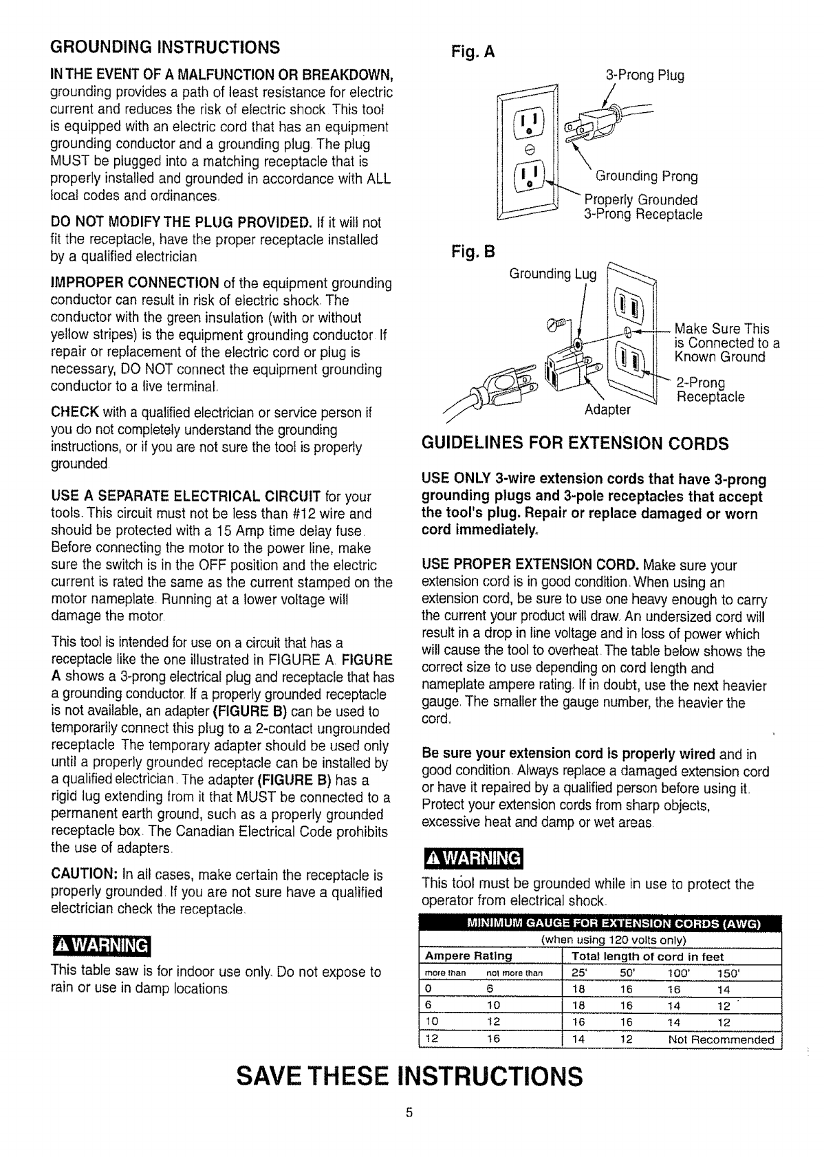
This tool is intended for use on a circuit that has a
receptacle like the one illustrated in FIGURE A FIGURE
A shows a 3-prong electrical plug and receptacle that has
a grounding conductor. If a properly grounded receptacle
is not available, an adapter (FIGURE B) can be used to
temporarily connect this plug to a 2-contact ungrounded
receptacle The temporary adapter should be used only
until a properly grounded receptacle can be installed by
a qualified electrician. The adapter (FIGURE B) has a
rigid tug extending from it that MUST be connected to a
permanent earth ground, such as a properly grounded
receptacle box. The Canadian Electrical Code prohibits
the use of adapters.
CAUTION: In all cases, make certain the receptacle is
properly grounded If you are not sure have a qualified
electrician check the receptacle.
This table saw is for indoor use only. Do not expose to
rain or use in damp locations
Fig. A
3-Prong Plug
Grounding Prong
Properly Grounded
3-Prong Receptacle
Fig. B
Grounding Lug _,,
apter
Make Sure This
is Connected to a
Known Ground
"" 2-Prong
Receptacle
GUIDELINES FOR EXTENSION CORDS
USE ONLY 3-wire extension cords that have 3-prong
grounding plugs and 3-pole receptacles that accept
the tool's plug. Repair or replace damaged or worn
cord immediately.
USE PROPER EXTENSION CORD. Make sure your
extension cord is in good condition, When using an
extension cord, be sure to use one heavy enough to carry
the current your product wit! draw. An undersized cord will
result in a drop in line voltage and in toss of power which
wil! cause the tool to overheat. The table below shows the
correct size to use depending on cord length and
nameplate ampere rating. If in doubt, use the next heavier
gauge. The smaller the gauge number, the heavier the
cord.
Be sure your extension cord is properly wired and in
good condition. Always replace a damaged extension cord
or have it repaired by a qualified person before using it
Protect your extension cords from sharp objects,
excessive heat and damp or wet areas
This tool must be grounded while in use to protect the
operator from electrical shock.
(when using 120 volts only)
Ampere Rating Total length of cord in feet
more lhan no1morelhan 2S' 50' t 00' 150'
0 6 18 16 16 14
6 10 t8 16 !4 12
1'0 12 t6 _' 16 14 12
12 16 14 12 Not Recommended
SAVE THESE INSTRUCTIONS
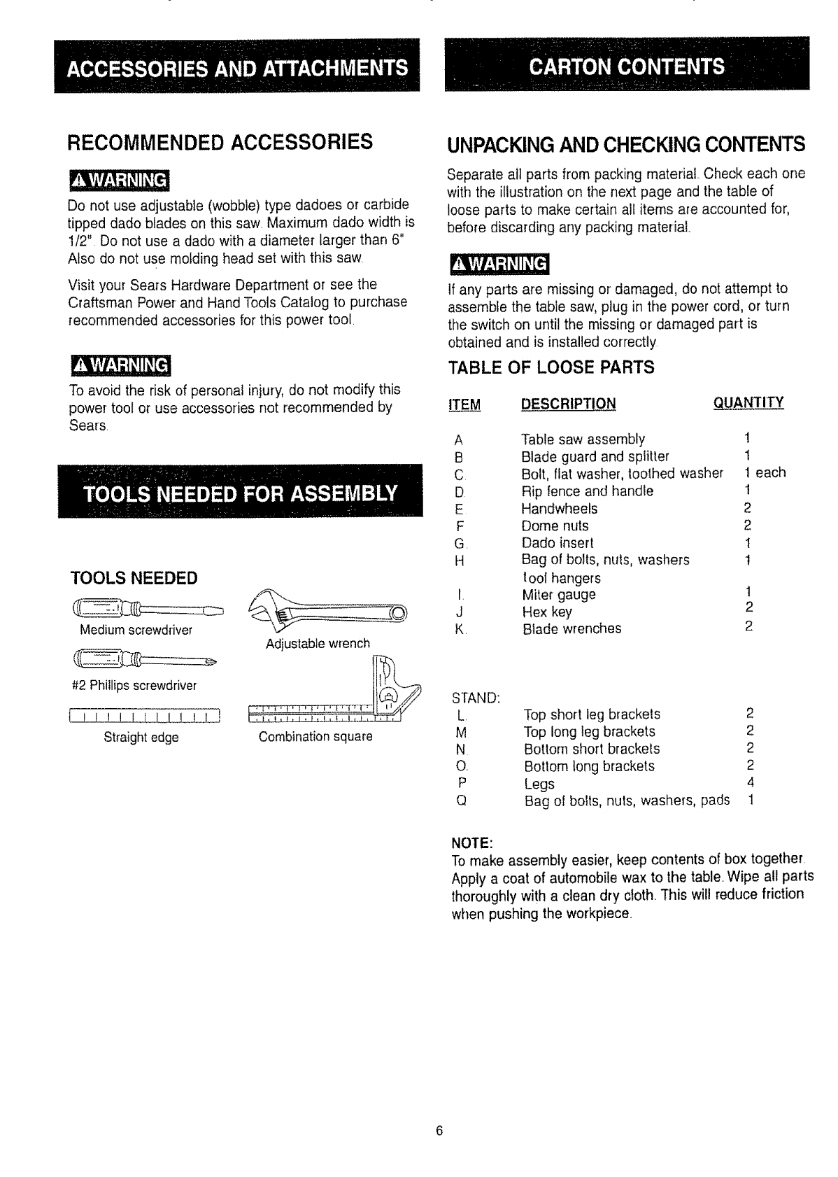
RECOMMENDED ACCESSORIES
Do not use adjustable (wobble) type dadoes or carbide
tipped dado blades on this saw. Maximum dado width is
112" Do not use a dado with a diameter larger than 6"
Also do not use molding head set with this saw
Visit your Sears Hardware Department or see the
Craftsman Power and Hand Tools Catalog to purchase
recommended accessories for this power tool.
To avoid the risk of personal injury, do not modify this
power tool or use accessories not recommended by
Sears
TOOLS NEEDED
Mediumscrewdriver
#2 Phillips screwdriver
Straight edge
Adjustable wrench
Combination square
UNPACKINGAND CHECKING CONTENTS
Separate all parts from packing material. Check each one
with the illustration on the next page and the table of
loose parts to make certain all items are accounted for,
before discarding any packing material.
If any parts are missing or damaged, do not attempt to
assemble the table saw, plug in the power cord, or turn
the switch on until the missing or damaged part is
obtained and is installed correctly
TABLE OF LOOSE PARTS
ITEM DESCRIPTION _TITY
A Table saw assembly 1
B Blade guard and splitter t
C Bolt, flat washer, toothed washer t each
D Rip fence and handle 1
E Handwheefs 2
F Dome nuts 2
G. Dado insert I
H Bag of bolts, nuts, washers I
lool hangers
I, Miter gauge 1
J Hex key 2
K. Blade wrenches 2
STAND:
L
M
N
O,
P
Q
Top short leg brackets 2
Top long leg brackets 2
Bottom short brackets 2
Bottom tong brackets 2
Legs 4
Bag of bolts, nuts, washers, pads 1
NOTE:
To make assembly easier, keep contents of box together.
Apply a coat of automobile wax to the table. Wipe all parts
thoroughly with a clean dry cloth. TMs will reduce friction
when pushing the workpiece.
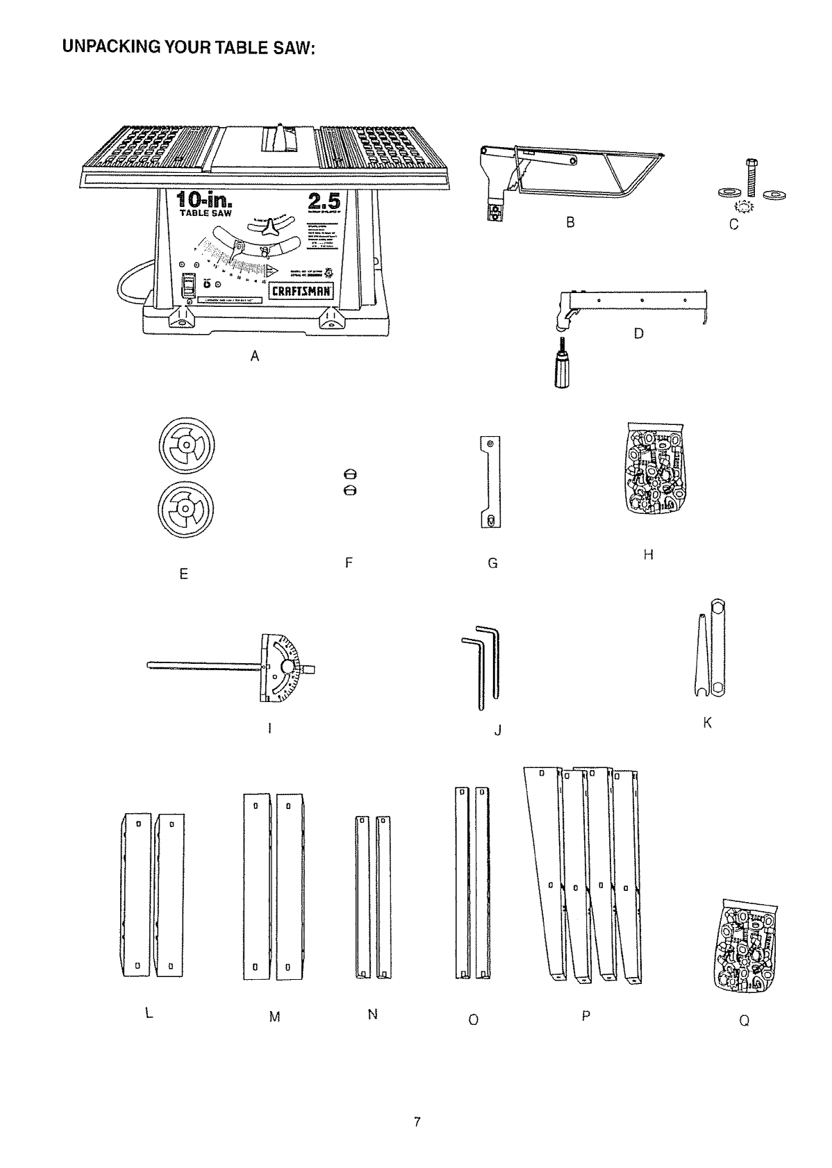
UNPACKING YOUR TABLE SAW:
A
B
_j_ • q=
D
Q
C
E
61
G
J
H
K
=
I°
i
[
i
i
0
L
i
0
°1
O
L
o
n
o
M
_L
N
-'5" -_
i
i
i
0
7,r-
1
0
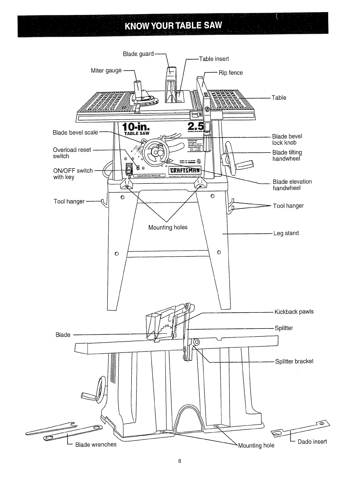
Miterg
Bladeg insert
Ripfence
Bladebevelscale
Overloadreset
switch
ONtOFFswitch
withkey
Toothan 0
lO.in.
TABLE SAW
J
0
Table
Blade bevel
lock knob
Blade tilting
handwheel
Blade elevation
handwheel
Tool hanger
Mounting holes Leg stand
Kickback pawls
Blade Splitter
Splitter bracket
_nches
Mounting hole
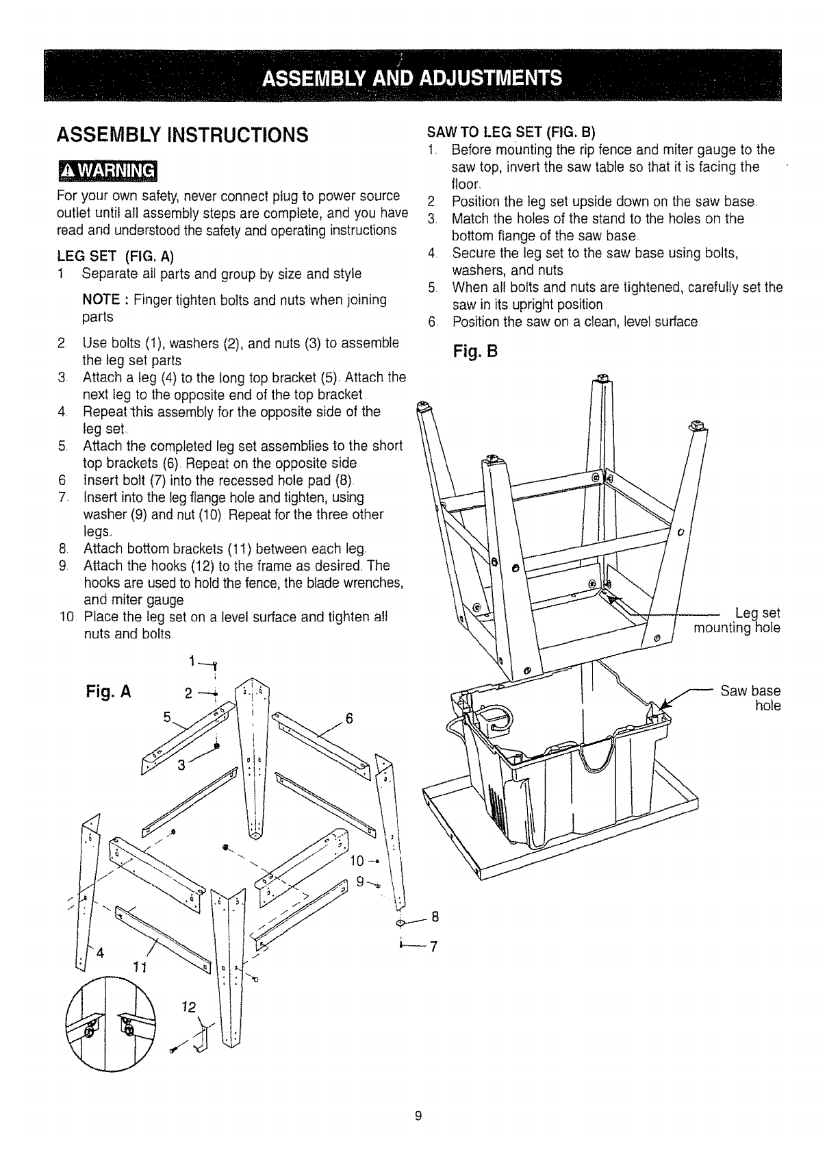
ASSEMBLY INSTRUCTIONS
For your own safety, never connect plug to power source
outlet until all assembly steps are complete, and you have
read and understood the safety and operating instructions
LEG SET (FIG. A)
I Separate all parts and group by size and style
NOTE : Finger tighten bolts and nuts when joining
parts
2 Use bolts (!), washers (2), and nuts (3) to assemble
the leg set parts
3 Attach a leg (4) to the tong top bracket (5). Attach the
next leg to the opposite end of the top bracket.
4. Repeat'this assembly for the opposite side of the
leg set.
5. Attach the completed leg set assemblies to the short
top brackets (6). Repeat on the opposite side
6 Insert bolt (7) into the recessed hole pad (8).
7. Insert into the leg flange hole and tighten, using
washer (9) and nut (10) Repeat for the three other
kegs..
8. Attach bottom brackets (11) between each leg.
9. Attach the hooks (12) to the frame as desired. The
hooks are used to hold the fence, the blade wrenches,
and miter gauge
I0 Place the leg set on a level surface and tighten al!
nuts and bolts
Fig. A
SAW TO LEG SET (FIG. B)
1. Before mounting the rip fence and miter gauge to the
saw top, invert the saw table so that it is facing the
floor.
2 Position the leg set upside down on the saw base
3. Match the holes of the stand to the holes on the
bottom flange of the saw base
4 Secure the leg set to the saw base using bolts,
washers, and nuts
5. When all bolts and nuts are tightened, carefully set the
saw in its upright position
6. Position the saw on a clean, level surface
Fig. B
Leg set
mounting hole
Saw base
hole
11
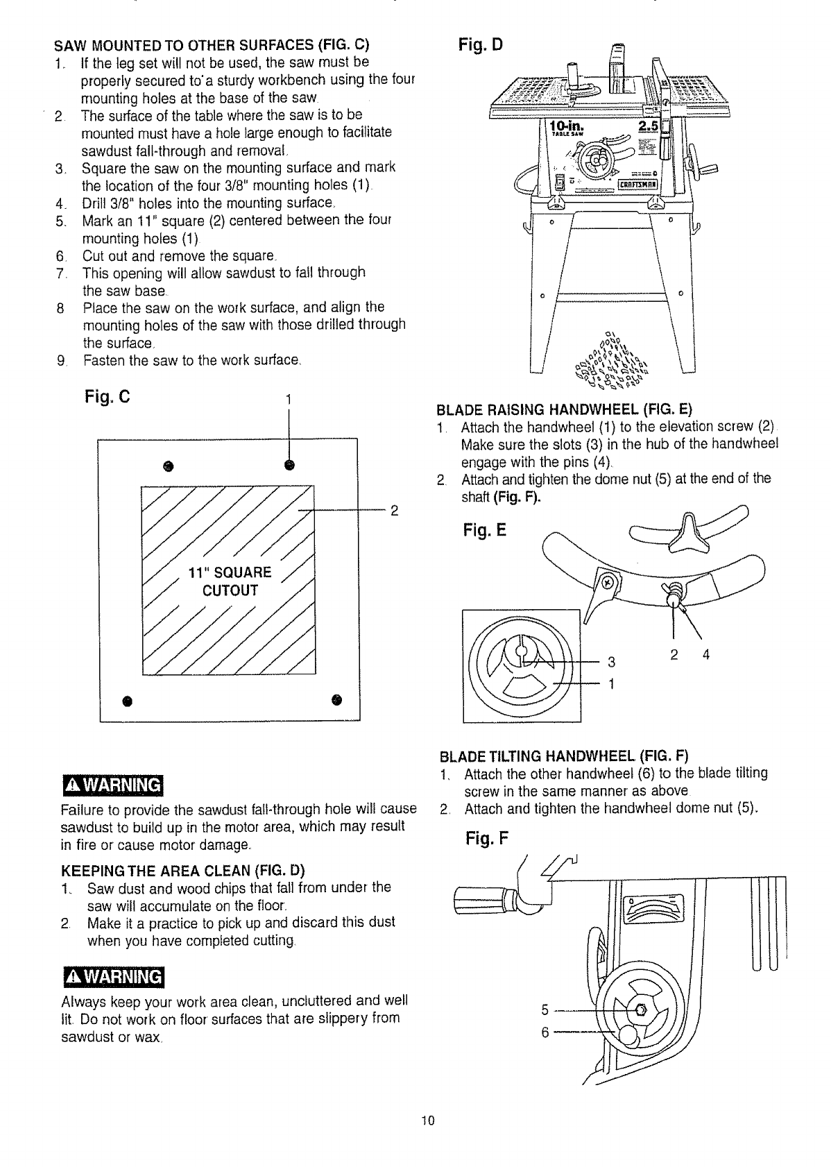
SAWMOUNTEDTOOTHERSURFACES(FIG.C)
1 Ifthelegsetwillnotbeused,thesawmustbe
properlysecuredto'asturdyworkbenchusingthefour
mountingholesatthebaseofthesaw
2 Thesurfaceofthetablewherethesawistobe
mountedmusthaveaholelargeenoughtofacilitate
sawdustfall-throughandremoval.
3_ Squarethesawonthemountingsurfaceandmark
thelocationof thefour3/8"mountingholes(1)
4 Dril!3/8"holesintothemountingsurface_
5. Markan11"square(2)centeredbetweenthefour
mountingholes(1)
6 Cutoutandremovethesquare
7 Thisopeningwillallow sawdust to fall through
the saw base
8 Place the saw on the work surface, and align the
mounting holes of the saw with those drilled through
the surface.
9 Fasten the saw to the work surface
Fig° C
2
O
Fig. D
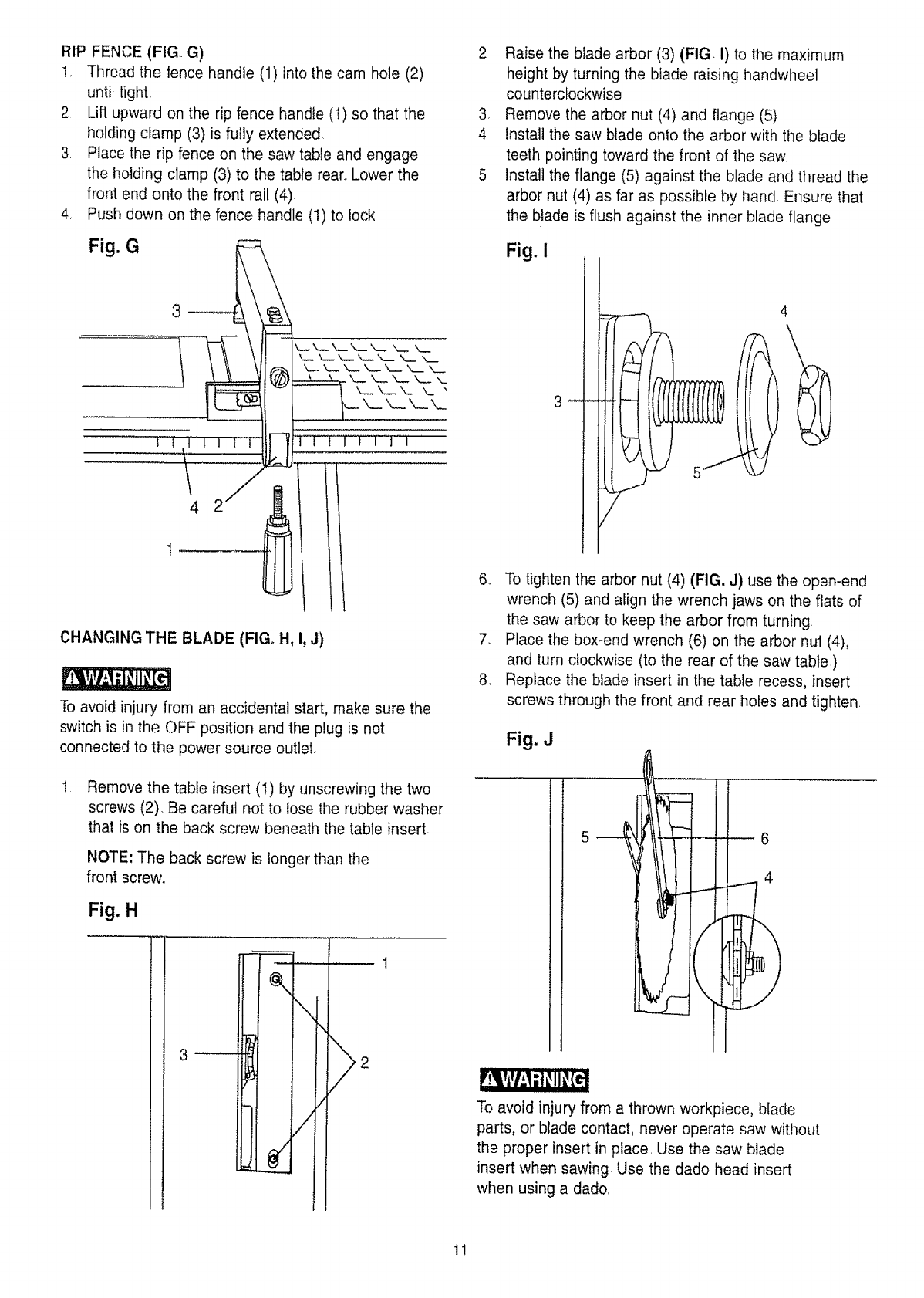
BLADE RAISING HANDWHEEL (FIG. E)
1 Attach the handwheel (1) to the elevation screw (2)
Make sure the slots (3) in the hub of the handwheel
engage with the pins (4)
2 Attach and tighten the dome nut (5) at the end of the
shaft (Fig. F).
Fig. E
3 2 4
Failure to provide the sawdust fall-through hole will cause
sawdust to build up in the motor area, which may result
in fire or cause motor damage
KEEPING THE AREA CLEAN (FIG. D)
1. Saw dust and wood chips that fall from under the
saw will accumulate on the floor
2 Make it a practice to pick up and discard this dust
when you have completed cutting
Always keep your work area clean, uncluttered and well
lit, Do not work on floor surfaces that are slippery from
sawdust or wax,
BLADE TILTING HANDWHEEL (FIG, F)
1. Attach the other handwheet (6) to the blade tilting
screw in the same manner as above
2 Attach and tighten the handwheel dome nut (5).
Fig. F
t0
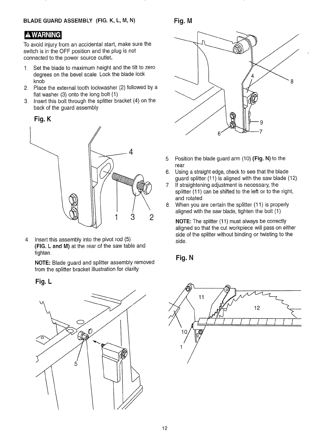
RIP FENCE (FIG. G)
t, Thread the fence handle (1) into the cam hole (2)
until tight
2 Lift upward on the rip fence handle (1) so that the
holding clamp (3) is fully extended
3 Place the rip fence on the saw table and engage
the holding clamp (3) to the table rear, Lower the
front end onto the front rail (4)
4, Push down on the fence handle (1) to lock
Fig. G
2 Raise the blade arbor (3) (FIG, I) to the maximum
height by turning the blade raising handwheel
counterclockwise
3 Remove the arbor nut (4) and flange (5)
4 install the saw blade onto the arbor with the blade
teeth pointing toward the front of the saw,
5 Install the flange (5) against the blade and thread the
arbor nut (4) as far as possible by hand Ensure that
the blade is flush against the inner blade flange
Fig. i
\
4
5
4
CHANGING THE BLADE (FIG. H, I, J)
To avoid injury from an accidental start, make sure the
switch is in the OFF position and the plug is not
connected to the power source outlet,
IRemove the table insert (1) by unscrewing the two
screws (2). Be careful not to lose the rubber washer
that is on the back screw beneath the table insert.
NOTE: The back screw is longer than the
front screw°
Fig. H
\
/
6 To tighten the arbor nut (4) (FIG. J) use the open-end
wrench (5) and align the wrench jaws on the fiats of
the saw arbor to keep the arbor from turning
7, Place the box-end wrench (6) on the arbor nut (4),
and turn clockwise (to the rear of the saw table)
8 Replace the blade insert in the table recess, insert
screws through the front and rear holes and tighten
Fig. J
5 6
4
)
To avoid injury from a thrown workpiece, blade
parts, or blade contact, never operate saw without
the proper insert in place. Use the saw blade
insert when sawing. Use the dado head insert
when using a dado.
tt
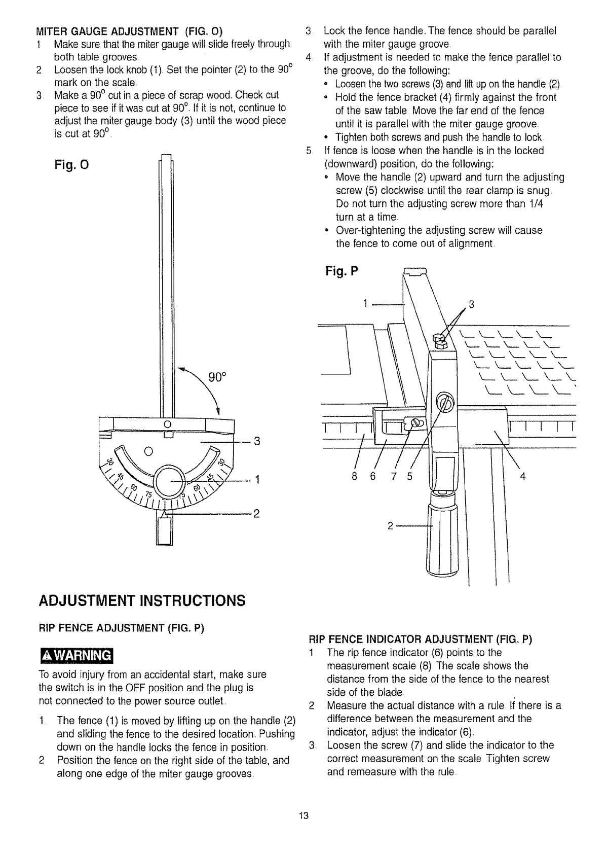
BLADE GUARD ASSEMBLY (FIG, K, L, M, N) Fig. M
To avoid injury from an accidental start, make sure the
switch is in the OFF position and the plug is not
connected to the power source outlet.
t. Set the blade to maximum height and the tilt to zero
degrees on the bevel scale, Lock the blade lock
knob,
2, Place the external tooth tockwasher (2) followed by a
flat washer (3) onto the tong bolt (1)
3, Insert this bolt through the splitter bracket (4) on the
back of the guard assembly.
Fig. K
4
1 3 2
4Insert this assembly into the pivot rod (5)
(FIG, L and M) at the rear of the saw table and
tighten,
NOTE: Blade guard and splitter assembly removed
from the splitter bracket illustration for clarity,
Fig. L
8
9
6
5 Position the blade guard arm (10) (Fig, N) to the
rear,
6., Using a straight edge, check to see that the blade
guard splitter (11) is aligned with the saw blade (12),
7, If straightening adjustment is necessary, the
splitter (11) can be shifted to the left or to the right,
and rotated,
8, When you are certain the splitter (I 1) is properly
aligned with the saw blade, tighten the bolt (1)
NOTE: The splitter (11) must always be correctly
aligned so that the cut workpiece will pass on either
side of the splitter without binding or twisting to the
side,
Fig. N
!1
t0
12
MITER GAUGE ADJUSTMENT (FIG_ O)
I Make sure that the miter gauge will slide freely through
both table grooves
2 Loosen the lock knob (t) Set the pointer (2) to the 900
mark on the scale.
3 Make a 90° cut in a piece of scrap wood_ Check cut
piece to see if it was cut at 900 if it is not, continue to
adjust the miter gauge body (3) until the wood piece
is cut at 900
Fig. 0
90°
i 3
_xLi_, ,"s\_--
ADJUSTMENT INSTRUCTIONS
3 Lock the fence handte..The fence should be parallel
with the miter gauge groove.
4 If adjustment is needed to make the fence parallel to
the groove, do the following:
• Loosen the two screws (3) and lift up on the handle (2)
• Hold the fence bracket (4) firmly against the front
of the saw table. Move the far end of the fence
until it is parallel with the miter gauge groove.
• Tighten both screws and push the handle to lock
5 If fence is loose when the handle is in the locked
(downward) position, do the following:
• Move the handle (2) upward and turn the adjusting
screw (5) clockwise until the rear clamp is snug.
Do not turn the adjusting screw more than 1/4
turn at a time.
° Over4ightening the adjusting screw will cause
the fence to come out of alignment,
Fig. Pt _:
////
8 6 7 5
RIP FENCE ADJUSTMENT (FIG. P)
To avoid injury from an accidental start, make sure
the switch is in the OFF position and the plug is
not connected to the power source outlet.
1 The fence (1)is moved by lifting up on the handle (2)
and sliding the fence to the desired location. Pushing
down on the handle locks the fence in position.
2 Position the fence on the right side of the table, and
along one edge of the miter gauge grooves.
RIP FENCE INDICATOR ADJUSTMENT (FIGo P)
1 The rip fence indicator (6) points to the
measurement scale (8) The scale shows the
distance from the side of the fence to the nearest
side of the blade
2 Measure the actual distance with a rule li there is a
difference between the measurement and the
indicator, adjust the indicator (6).
3 Loosen the screw (7) and slide the indicator to the
correct measurement on the scale Tighten screw
and remeasure with the rule
I3
To avoid injury from an accidental start, make sure the
switch is in the OFF position and the plug is not
connected to the power source outlet.
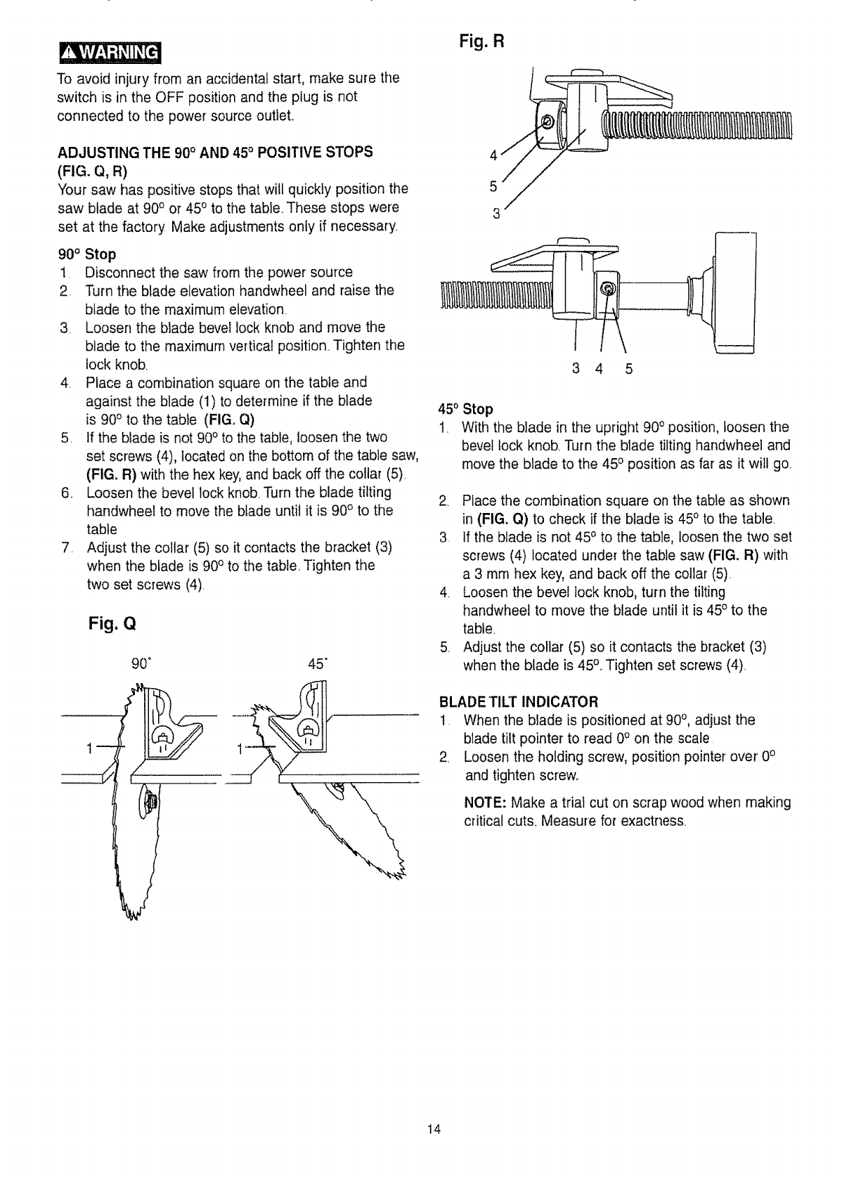
ADJUSTING THE 900 AND 45° POSITIVE STOPS
(FIG. Q, R)
Your saw has positive stops that will quickly position the
saw blade at 90 o or 45o to the table, These stops were
set at the factory Make adjustments oniy if necessary
90° Stop
1 Disconnect the saw from the power source
2. Turn the blade elevation handwheel and raise the
blade to the maximum elevation.
3 Loosen the blade bevel lock knob and move the
blade to the maximum vertical position. Tighten the
lock knob.
4. Place a combination square on the table and
against the blade (1) to determine if the blade
is 90o to the table (FIG. Q)
5. if the blade is not 90° to the table, loosen the two
set screws (4), located on the bottom of the table saw,
(FIG. R) with the hex key, and back off the collar (5),
6, Loosen the bevel lock knob.Turn the blade tilting
handwheet to move the blade until it is 90° to the
table
7. Adjust the collar (5) so it contacts the bracket (3)
when the blade is 90° to the table Tighten the
two set screws (4).
Fig. Q
90" 45 =
Fig. R
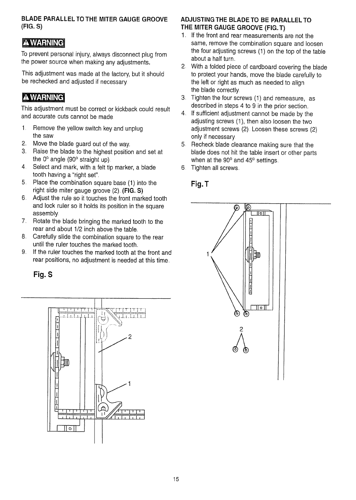
450
1,
Stop
With the blade in the upright 900 position, loosen the
bevel lock knob. Turn the blade tilting handwheel and
move the blade to the 450 position as far as it will go.
2 Place the combination square on the table as shown
in (FIGo Q) to check if the blade is 45° to the table.
3. If the blade is not 450 to the table, loosen the two set
screws (4) located under the table saw (FIG_ R) with
a 3 mm hex key, and back off the collar (5).
4. Loosen the bevel lock knob, turn the tilting
handwheel to move the blade until it is 45° to the
table.
5. Adjust the collar (5) so it contacts the bracket (3)
when the blade is 45°° Tighten set screws (4)
BLADE TILT INDICATOR
!. When the blade is positioned at 90°, adjust the
blade tilt pointer to read 0° on the scale
2. Loosen the holding screw, position pointer over 0°
and tighten screw.
NOTE: Make a trial cut on scrap wood when making
critical cuts. Measure for exactness.
t4
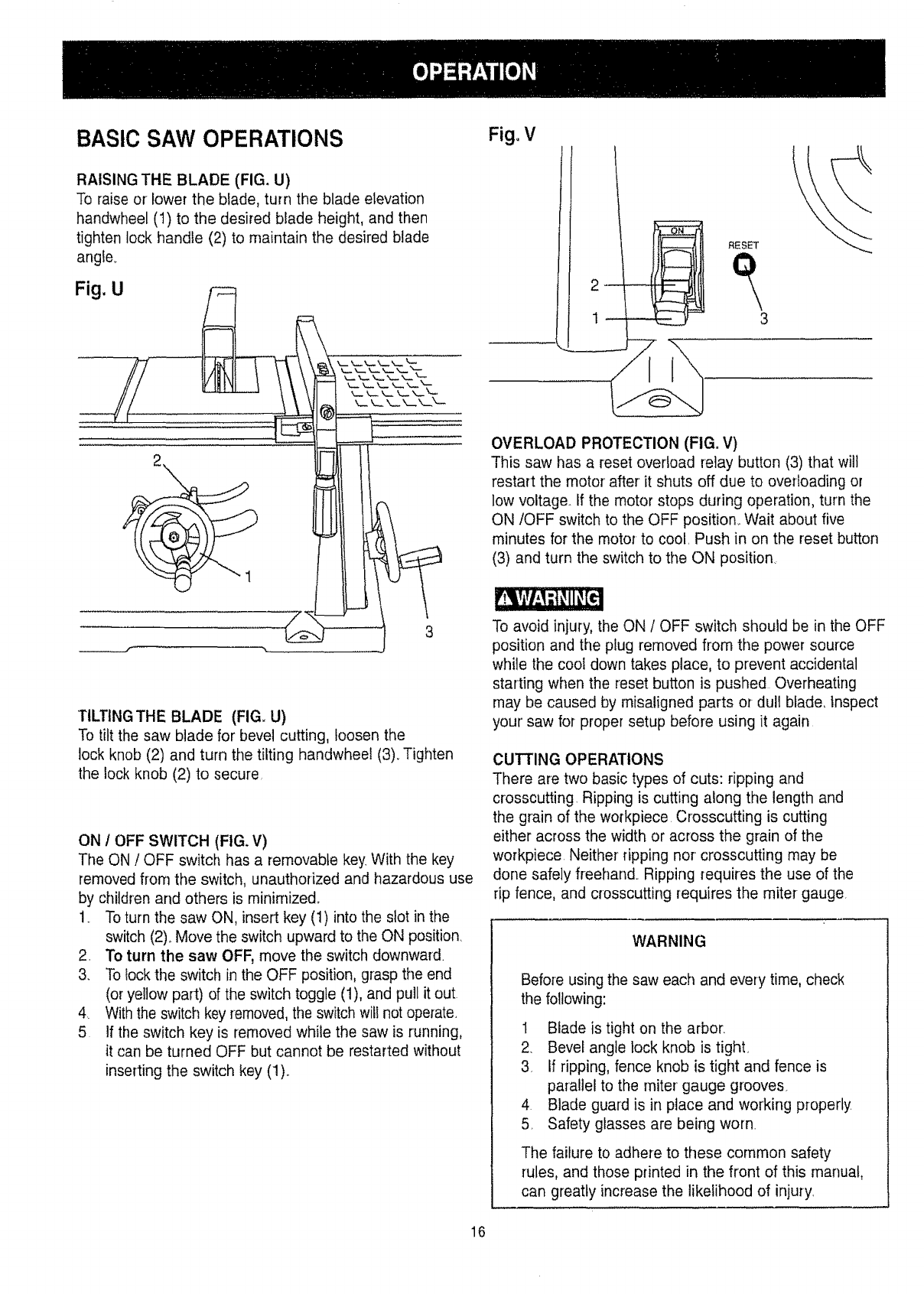
BLADE PARALLEL TO THE MITER GAUGE GROOVE
(FIG. S)
To prevent personal injury, always disconnect plug from
the power source when making any adjustments,
This adjustment was made at the factory, but it should
be rechecked and adjusted if necessary
This adjustment must be correc' or kickback could result
and accurate cuts cannot be made
!. Remove the yellow switch key and unplug
the saw
2.. Move the blade guard out of the way,.
3_. Raise the blade to the highest position and set at
the 0° angle (90° straight up)
4. Select and mark, with a felt tip marker, a blade
tooth having a "right set",
5. Place the combination square base (1) into the
right side miter gauge groove (2). (FIG. S)
6, Adjust the rule so it touches the front marked tooth
and lock ruler so it holds its position in the square
assembly.
7. Rotate the blade bringing the marked tooth to the
rear and about 1/2 inch above the table,
8. Carefully slide the combination square to the rear
until the ruler touches the marked tooth.
9, If the ruler touches the marked tooth at the front and
rear positions, no adjustment is needed at this time,
Fig. S
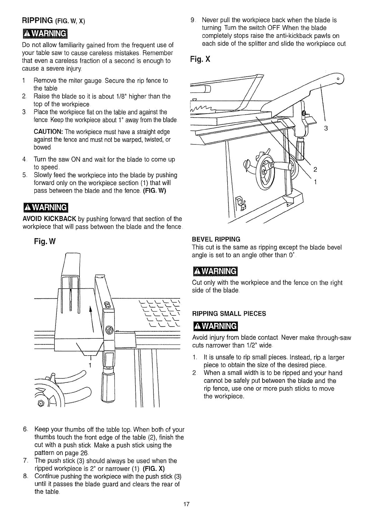
ADJUSTING THE BLADE TO BE PARALLEL TO
THE MITER GAUGE GROOVE (FIG.T)
1_ If the front and rear measurements are not the
same, remove the combination square and loosen
the four adjusting screws (1) on the top of the table
about a half turn,
2. With a folded piece of cardboard covering the blade
to protect your hands, move the blade carefully to
the left or right as much as needed to align
the blade correctly
3. Tighten the four screws (1) and remeasure, as
described in steps 4 to 9 in the prior section..
4. If sufficient adjustment cannot be made by the
adjusting screws (1), then also loosen the two
adjustment screws (2). Loosen these screws (2)
only if necessary
5. Recheck blade clearance making sure that the
blade does not hit the table insert or other parts
when at the 90° and 45 °settings.
6, Tighten all screws.
Fig.T
C_:i]_:i:[i:.:[i_:.:C;.!_ i
1
15
BASIC SAW OPERATIONS
RAISING THE BLADE (FIG, U)
To raise or lower the blade, turn the blade elevation
handwheel (1) to the desired blade height, and then
tighten lock handle (2) to maintain the desired blade
angle,,
TILTING THE BLADE (FIG, U)
To tilt the saw blade for bevel cutting, loosen the
lock knob (2) and turn the tilting handwhee! (3). Tighten
the lock knob (2) to secure
ON /OFF SWITCH (FIG, V)
The ON /OFF switch has a removable key With the key
removed from the switch, unauthorized and hazardous use
by children and others is minimize&
1. To turn the saw ON, insert key (1) into the slot in the
switch (2). Move the switch upward to the ON position.
2. To turn the saw OFF, move the switch downward
3. To lock the switch in the OFF position, grasp the end
(or yellow part) of the switch toggle (1), and pull it out
4 With the switch key removed, the switch will not operate.
5 If tile switch key is removed while the saw is running,
it can be turned OFF but cannot be restarted without
inserting the switch key (1)..
Fig. V
t
RESET
OVERLOAD PROTECTION (FIG. V)
This saw has a reset overload relay button (3) that wilt
restart the motor' after it shuts off due to overloading or
low voltage. If the motor stops during operation, turn the
ON/OFF switch to the OFF position_ Wait about five
minutes for the motor to cool. Push in on the reset button
(3) and turn the switch to the ON position.
To avoid injury, the ON /OFF switch should be in the OFF
position and the plug removed from the power source
while the cool down takes place, to prevent accidental
starting when the reset button is pushed Overheating
may be caused by misaligned parts or dull blade, Inspect
your' saw for proper setup before using it again
CUTTING OPERATIONS
There are two basic types of cuts: ripping and
crosscutting. Ripping is cutting along the length and
the grain of the workpiece Crosscutting is cutting
either across the width or across the grain of the
workpiece Neither ripping nor crosscutting may be
done safely freehand. Ripping requires the use of the
rip fence, and crosscutting requires the miter gauge
WARNING
Before using the saw each and every time, check
the following:
1 Blade is tight on the arbor.
2. Bevel angle lock knob is tight.
3. If ripping, fence knob is tight and fence is
parallel to the miter gauge grooves.
4 Blade guard is in place and working properly
5 Safety glasses are being worn.
The failure to adhere to these common safety
rules, and those printed in the front of this manual,
can greatly increase the likelihood of injury
16
RIPPING (FIG. W, X)
Do not allow familiarity gained from the frequent use of
your table saw to cause careless mistakes. Remember
that even a careless fraction of a second is enough to
cause a severe injury
1 Remove the miter gauge, Secure the rip fence to
the table
2. Raise the blade so it is about 1/8" higher than the
top of the workpiece
3 Place the workpiece flat on the table and against the
fence Keep the workpiece about t" away from the blade
CAUTION: The workpiece must have a straight edge
against the fence and must not be warped, twisted, or
bowed
4, Turn the saw ON and wait for the blade to come up
to speed,
5. Slowly feed the workpiece into the blade by pushing
forward only on the workpiece section (I) that will
pass between the blade and the fence, (FIG. W)
AVOID KICKBACK by pushing forward that section of the
workpiece that wilt pass between the blade and the fence,
Fig.W
®
t
I
i
i
k__ ",,_ k._ k__ k_ \
k_ ,, _ -,,.._ k__ k-
k__ _.._ k_ k__
,Never pull the workpiece back when the blade is
turning Turn the switch OFE When the blade
completely stops raise the anti-kickback pawls on
each side of the splitter and slide the workpiece out
Fig. X
2
1
BEVEL RIPPING
This cut is the same as ripping except the blade bevel
angle is set to an angle other than 0°
Cut only with the workpiece and the fence on the right
side of the blade,
RIPPING SMALL PIECES
Avoid injury from blade contact. Never make through-saw
cuts narrower than 1/2" wide.
,
2
It is unsafe to rip small pieces. Instead, rip a larger
piece to obtain the size of the desired piece.
When a small width is to be ripped and your hand
cannot be safely put between the blade and the
rip fence, use one or more push sticks to move
the workpiece,,
6. Keep your thumbs off the table top., When both of your
thumbs touch the front edge of the table (2), finish the
cut with a push stick Make a push stick using the
pattern on page 26,
7. The push stick (3) should always be used when the
ripped workpiece is 2" or narrower (1) (FIG. X)
8. Continue pushing the workpiece with the push stick (3)
until it passes the blade guard and clears the rear of
the table
t7
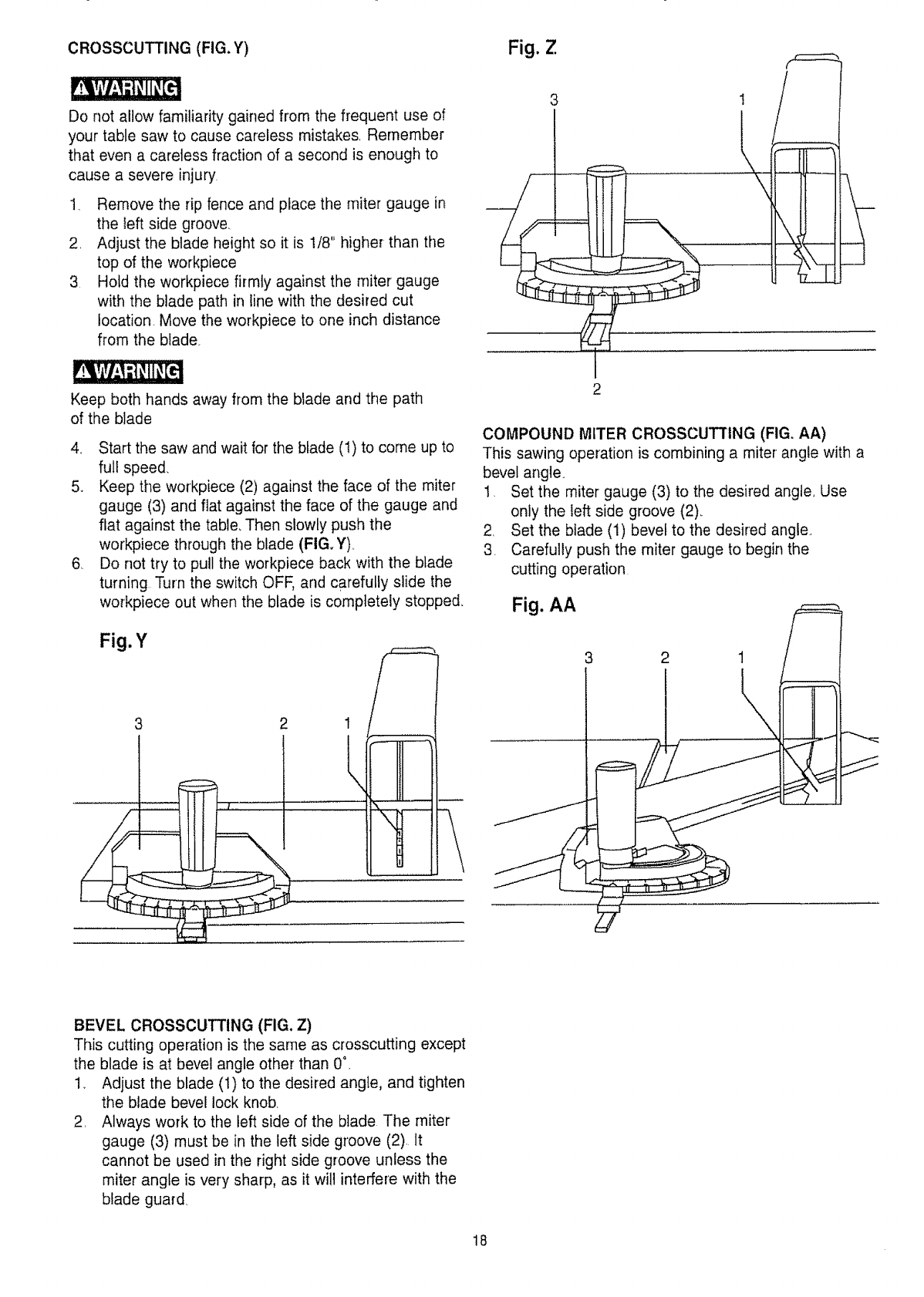
CROSSCUTTING (FIG. Y)
Do not allow familiarity gained from the frequent use of
your table saw to cause careless mistakes, Remember
that even a careless fraction of a second is enough to
cause a severe injury
1. Remove the rip fence and place the miter gauge in
the left side groove,
2, Adjust the blade height so it is 1/8" higher than tile
top of the workpiece
3 Hold the workpiece firmly against the miter gauge
with the blade path in line with the desired cut
location. Move the workpiece to one inch distance
from the blade.
Keep both hands away from the blade and the path
of the blade
4, Start the saw and wait for the blade (1) to come up to
full speed,
5. Keep the workpiece (2) against the face of the miter
gauge (3) and flat against the face of the gauge and
flat against the table, Then slowly push the
workpiece through the blade (FIG. Y),
6, Do not try to pull the workpiece back with the btade
turning Turn the switch OFF, and carefully slide the
workpiece out when the blade is completely stopped.
Fig. Y
1
Itl I
!1! !
\rt 1
tl= i
|!| I
Fig. Z
3
I
2
!
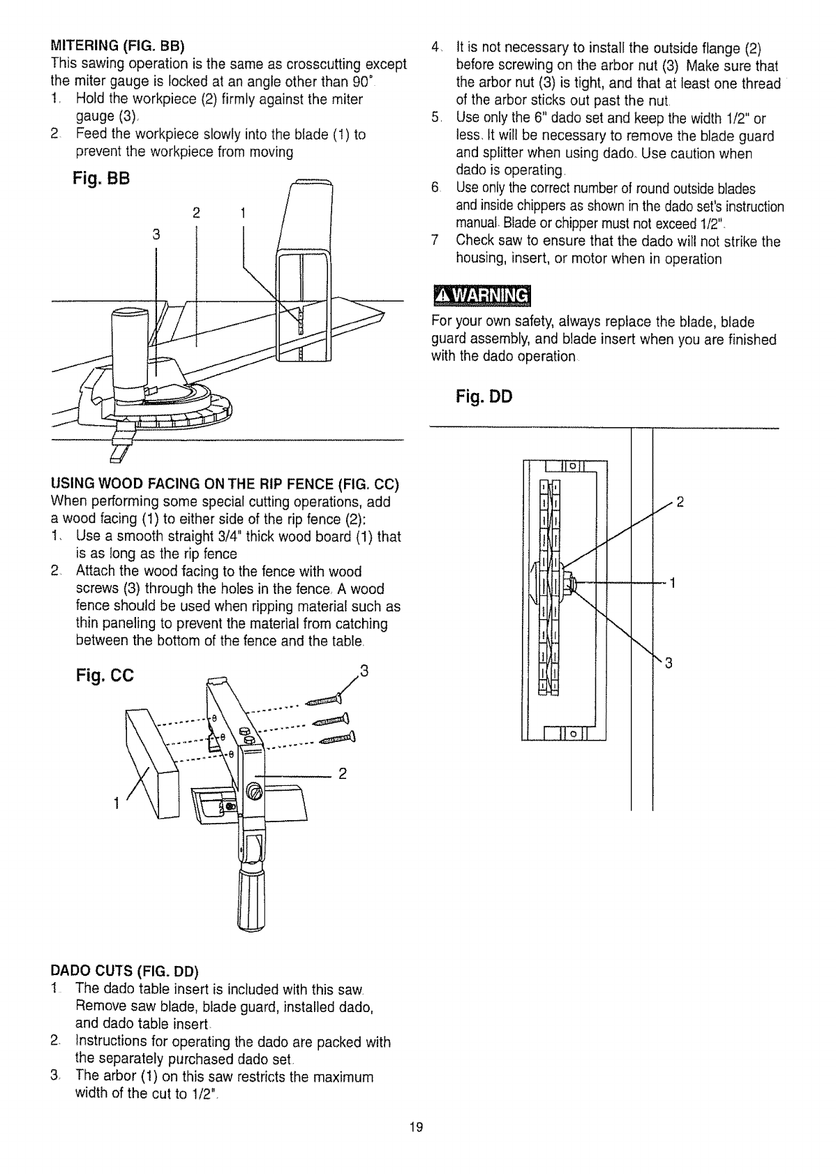
COMPOUND MITER CROSSCUTTING (FIG. AA)
This sawing operation is combining a miter angle with a
bevel angle
1, Set the miter gauge (3) to the desired angle, Use
only the left side groove (2),,
2 Set the blade (1) bevel to the desired angle,
3. Carefully push the miter gauge to begin the
cutting operation
Fig. AA
BEVEL CROSSCUTTING (FIG. Z)
This cutting operation is the same as crosscutting except
the blade is at bevel angle other than 0°.
1_ Adjust the blade (t) to the desired angle, and tighten
the blade bevel lock knob,
2, Always work to the left side of the blade The miter
gauge (3) must be in the left side groove (2), It
cannot be used in the right side groove unless the
miter angle is very sharp, as it will interfere with the
blade guard.
t8
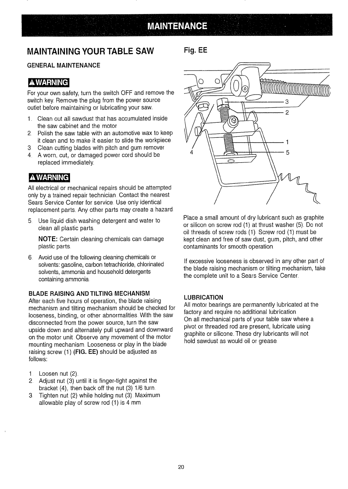
MITERING (FIG. BB)
This sawing operation is the same as crosscutting except
the miter gauge is locked at an angle other than 90 °
!, Hold the workpiece (2) firmly against the miter
gauge (3)_
2. Feed the workpiece slowly into the blade (1) to
prevent the workpiece from moving
Fig. BB F===
2 1
3
USING WOOD FACING ON THE RIP FENCE (FIG. CO)
When performing some special cutting operations, add
a wood facing (1) to either side of the rip fence (2):
I, Use a smooth straight 3/4" thick wood board (1) that
is as long as the rip fence
2, Attach the wood facing to the fence with wood
screws (3) through the holes in the fence, A wood
fence should be used when ripping material such as
thin paneling to prevent the material from catching
between the bottom of the fence and the table,
Fig. CC
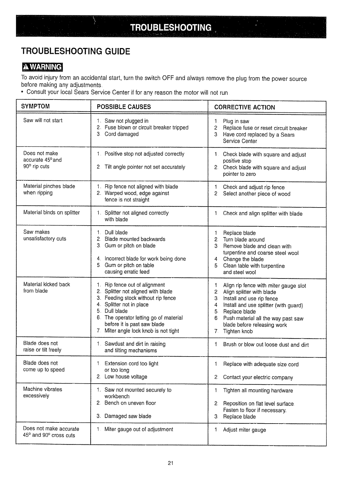
4. It is not necessary to install the outside flange (2)
before screwing on the arbor nut (3) Make sure that
the arbor nut (3) is tight, and that at least one thread
of the arbor sticks out past the nut
5. Use only the 6" dado set and keep the width 1/2" or
less. It will be necessary to remove the blade guard
and splitter when using dadoo Use caution when
dado is operating.
6 Use only the correct number of round outside blades
and inside chippers as shown in the dado set's instruction
manual. Blade or chipper must not exceed 1/2".
7 Check saw to ensure that the dado will not strike the
housing, insert, or motor when in operation
For your own safety, always replace the blade, blade
guard assembly, and blade insert when you are finished
with the dado operation
Fig. DD
j2
J
\"3
DADO CUTS (FIG. DD)
! The dado table insert is included with this saw.
Remove saw blade, blade guard, installed dado,
and dado table insert.
2. Instructions for operating the dado are packed with
the separately purchased dado set.
3. The arbor (1) on this saw restricts the maximum
width of the cut to 112".
19
MAINTAINING YOUR TABLE SAW
GENERAL MAINTENANCE
For your own safety, turn the switch OFF and remove the
switch key. Remove the plug from the power source
outlet before maintaining or' lubricating your saw..
1. Clean out all sawdust that has accumulated inside
the saw cabinet and the motor
2 Polish the saw table with an automotive wax to keep
it clean and to make it easier to slide the workpiece
3 Clean cutting blades with pitch and gum remover
4. A worn, cut, or damaged power cord should be
replaced immediately.
All electrical or mechanical repairs should be attempted
only by a trained repair technician. Contact the nearest
Sears Service Center for service. Use only identical
replacement parts. Any other parts may create a hazard.
5. Use liquid dish washing detergent and water to
clean all plastic parts.
NOTE: Certain cleaning chemicals can damage
plastic parts
,Avoid use of the following cleaning chemicals or
solvents: gasoline, carbon tetrachloride, chlorinated
solvents, ammonia and household detergents
containing ammonia.
BLADE RAISING AND TILTING MECHANISM
After each five hours of operation, the blade raising
mechanism and tilting mechanism should be checked for
looseness, binding, or other abnormalities With the saw
disconnected from the power source, turn the saw
upside down and alternately pull upward and downward
on the motor unit Observe any movement of the motor
mounting mechanism Looseness or play in the blade
raising screw (1) (FIG, EE) should be adjusted as
follows:
1 Loosen nut (2),
2, Adjust nut (3) until it is finger-tight against the
bracket (4), then back off the nut (3) t/6 turn,
3 Tighten nut (2) while holding nut (3), Maximum
allowable play of screw rod (1) is 4 rnm
Fig. EE
2
Place a small amount of dry lubricant such as graphite
or silicon on screw rod (1) at thrust washer (5)_ Do not
oil threads of screw rods (1) Screw rod (1) must be
kept clean and free of saw dust, gum, pitch, and other
contaminants for smooth operation.
If excessive looseness is observed in any other part of
the blade raising mechanism or tilting mechanism, take
the complete unit to a Sears Service Center.
LUBRICATION
All motor bearings are permanently lubricated at the
factory and require no additional lubrication
On all mechanical parts of your table saw where a
pivot or threaded rod are present, lubricate using
graphite or silicone These dry lubricants will not
hold sawdust as would oil or grease
2O
TROUBLESHOOTING GUIDE
To avoid injury from an accidental start, turn the switch OFF and always remove the plug from the power source
before making any adjustments.
• Consult your local Sears Service Center if for any reason the motor will not run
SYMPTOM POSSIBLE CAUSES
Saw will not start
Does not make
accurate 45° and
90° rip cuts
Material pinches blade
when ripping
Material binds on splitter
Saw makes
unsatisfactory cuts
Material kicked back
from blade
Blade does not
raise or tilt freely
Blade does not
come up to speed
Machine vibrates
excessively
Does not make accurate
45° and 90° cross cuts
I, Saw not plugged in
2. Fuse blown or circuit breaker tripped
3 Cord damaged
1. Positive stop not adjusted correctly
2 Tilt angle pointer not set accurately
I. Rip fence not aligned with biade
2, Warped wood, edge against
fence is not straight
t.. Splitter not aligned correctly
with blade
1. Dull blade
2. Blade mounted backwards
3. Gum or pitch on blade
4. Incorrect bladefor work being done
5 Gum or pitch on table
causing erraticfeed
I, Rip fence out of alignment
2, Splitter not aligned with blade
3, Feeding stock without rip fence
4. Splitter not in place
5, Dull blade
6, The operator letting go of material
before it is past saw blade
7 Miter angle lock knob is not tight
I. Sawdust and dirt in raising
and tilting mechanisms
1 Extension cord too light
or too tong
2, Low house voltage
t,, Saw not mounted securely to
workbench
2. Bench on unevenfloor
3. Damaged saw blade
t Miter gauge out of adjustment
CORRECTIVE ACTION
....,'., ,. ,;., ,..,,HH ..........
1 Plugin saw
2 Replace fuse or reset circuit breaker
3 Have cord replaced by a Sears
Service Center
! Check blade with square and adjust
positive stop
2 Check blade with square and adjust
pointer to zero
1 Check and adjust rip fence
2 Select another piece of wood
1 Check and align splitter with blade
I Replace blade
2 Turn blade around
3 Removeblade and clean with
turpentine and coarse steel wool
4 Change the blade
5 Clean table with turpentine
and steelwool
! Align rip fencewith miter gauge slot
2 Align splitter with blade
3 Install and use rip fence
4 Install and use splitter (with guard)
5 Replaceblade
6 Push material all the way past saw
blade before releasing work
7 Tighten knob
,,rr
Brush or blow out loose dust and dirt
1 Replacewith adequate size cord
2 Contact your electric company
1 Tighten all mounting hardware
2. Reposition on flat level surface
Fasten to floor if necessary.
3, Replace blade
1 Adjust miter gauge
2t
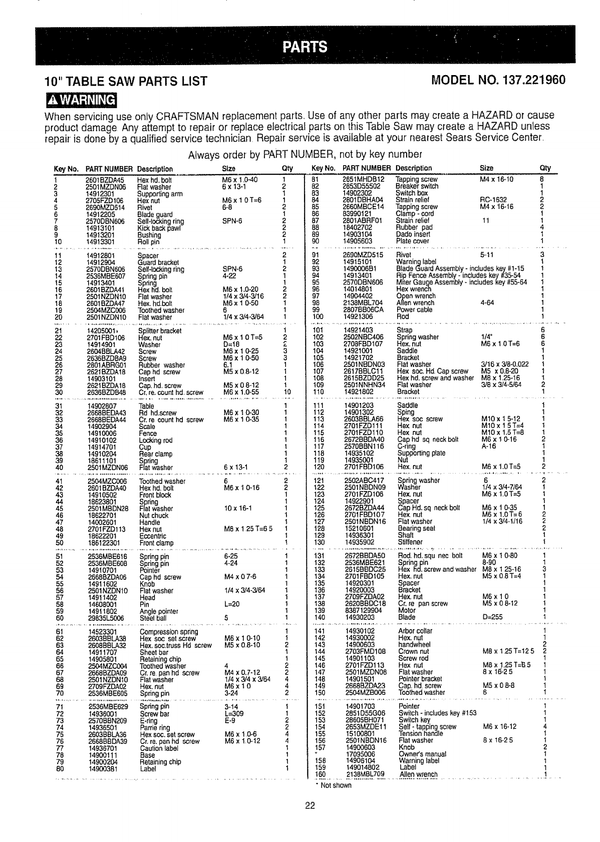
10" TABLE SAW PARTS LIST MODEL NO. 137.221960
When servicing use only CRAFTSMAN replacement parts. Use of any other parts may create a HAZARD or cause
product damage Any attempt to repair or replace electrical parts on this Table Saw may create a HAZARD unless
repair is done by a qualified service technician Repair service is available at your nearest Sears Service Center,
Always order by PART NUMBER, not by key number
Key No. PART NUMBER Description Size
i2601BZDA45 Hex hd, bolt M6 x1,0-40
22501MZDN06 Rat washer 6x13-I
314912301 Supporting arm
4 2705FZD168 Hex nut M6 x 1 0 "i'=6
5 2590MZD514 Rivet 6-8
6 14912205 Blade guard
7 2570DEN606 Sell-locking ring SPN-6
8 14913101 Kick back pawt
9 14913201 Bushing
10 14913301 RoII pin
Qty KeyNo,
1 8t
282
1 83
184
2 85
1 86
287
288
289
1 9O
1t 14912801 Spacer
12 14912904 Guard bracket
13 2570DBN606 Self-locking ring SPN-6
t4 2536MBE607 Spring pin 4-22
t 5 14913401 Spring
16 2601BZDA41 Hex hal.bolt M6 x1.0-20
17 2501NZDN10 Flat washer 1/4 x 3/4,3/16
18 2601BZDA47 Hex. hd,bett M6 x1 0-50
19 2504MZC006 Toothed washer 6
20 2501NZDNlO Fiat washer 1/4 x3/4-3/64
2
1
2
1
!
2
2
1
1
1
21 14205001 _ Splitter bracket t
22 2701FBD106 Hex, nut M8 x1 0 T-=5 2
23 14914901 Washer D=t8 2
24 2604BBLA42 Screw M6 x t 0-25 3
25 2636BZDBA9 Screw M6 x1 0-50 3
26 2601ABRG01 Rubber washer 6.1 1
27 2621BZDAI8 Cap hd screw M5 x 08-t2 1
28 14903101 insert 1
29 2621BZDA18 Cap. hal, screw M5 x0 8-12 t
30 2636BZDB48 L;r,re, count hd_screw M6 x1,0-55 10
3t 14902807 Table
32 2668BEDA43 Rd hd.screw M6 xt 0-30
33 2668BEDA4,1 Cr, re count hd screw M6 x I 0-35
34 14902904 Scale
35 14910006 Fence
36 14910102 Locking rod
37 14914701 Cup
38 14910204 Rear cramp
39 18611101 Spring
40 2501MZDN08 Fiat washer 6 x t3-1
1
1
1
1
1
1
1
!
1
2
PART NUMBER Description Size Qty
2651MHDBt2 Tapping screw M4 x 16-10 8
2853D55502 ureaker switch 1
14902302 Switch box 1
2801DBHA04 Strain relief RC-1632 2
2660MBCE14 Tapping screw M4 x t6-18 2
83990121 Clamp - core 1
2801ABRF01 Strain relief 11 1
18402702 Rubber pad 4
14903104 Dado insert 1
14905603 Plate cover 1
91 2690MZD515 Rival 5-11 3
92 14915101 Warning label t
93 1490006B1 Biade Guard Assembly - includes key #1-15 !
94 14913401 R!p. Fence Assembly -inctudes key f135--54 t
95 2570DEN606 M_ter Gauge Assembly * inctudes key #55-64 t
96 14014801 Hex wrenc_n 1
97 14904402 Open wrench 1
98 2138MBL704 Allen wrench 4-64 1
99 2807BB08CA Power cable 1
100 14921306 Rod 1
101 14921403 Strap 6
102 2502NBC406 Spring washer t/4" 6
103 2708FED107 Hex, nut M5 x 10T=6 6
104 14921001 Saddle 1
t05 14921702 Bracket 1
106 2501NBDN03 Flat washer 3/t6 x3/8-0.022 t
107 2617BBLC11 Hex so(:;.Hd Cap screw M5 x0,8,20 !
t08 2815BZDD25 Hex hd, screw and washer M8 x 1.25-16 !
t09 2501NNHN34 Flat washer 3/8 x 3/4-5/64 2
110 14921802 Brad_t 1
111 14901203 Saddle t
1t2 14901302 Sping
t!3 2803BBLA68 Hex soc screw MIO xI 5-12
!14 2701FZD111 Hex nut MI0 x 15T=4
t15 2701FZD110 Hex nut MIO x 1.5t"=8
t16 2672BBDA40 Cap hd sq neck belt M6 x 1 0-16
!17 2570BBN116 C-ring A-16
118 14935102 Supporting plate
119 14935001 Nut
120 2701FBD106 Hex, nut M5 x 1.0 T-=5
1
t
t
I
2
1
1
1
2
41 2504MZC006 Toothed washer 6
42 2801BZDA40 Hex hd, bolt M6 xt 0-16
43 14910502 Frontblock
44 18623801 Spring
45 2501MBDN28 Flat washer t0 x t6-1
46 18622701 Nut chuck
47 14002601 Handle
48 2701FZD1 t3 Hex nut M8 x 1 25 T=6 5
49 18622201 Eccentric
50 186122301 Front clamp
2
2
1
1
1
1
t
!
t
t
51 2536MBE616 Spring pin 6-25 1
52 2536MBE608 Spring pin 4-24 1
53 14910701 Pointer 1
54 2668BZDA06 Cap hd screw M4 x 0 7-6 1
55 t491 t602 Knob 1
56 2501NZDNlO Rat washer 114x 3/4-3/64 1
57 t 4911402 Head t
58 14608001 Pin L=20 1
59 t49! 1802 Angle pointer !
60 29835L5006 Steel ball 5I
6I 14523301 Compsass!on spring t
62 2683BBLA38 Hex soc set screw M6 x 1 0-t0 !
63 2608BBLA32 Hex. see.truss Hd screw M5 x 0.8-10 2
64 14911707 Sheet bar 1
65 14905801 Retaining chip 1
66 2504MZC004 Toothed washer 4 2
67 2668BZDA09 Cr. re pan hd screw M4 x 0.7-12 2
68 2501NZDNI0 Fiat washer 114 x 3/4 x 3/64 4
69 2709FZDA02 Hex. nut M6 x 1 0 4
70 2536MBEB05 Spring pin 3-24 2
7t 2536MBE629 Spring pin 3-t4 I
72 14936001 Screw bar L=309 t
73 2570BBN209 E-ring E-9 2
74 14936501 Pattie ring 2
75 2603BBLA36 Hex soc. set screw M6 x10-6 4
76 2658BBDA39 Cr. re. pan hd screw M6 x10-t2 4
77 14936701 Caulion Iabel 1
78 t4900111 Base 1
79 14900204 Retaining chip 1
80 14900381 Label t
121 2502ABC417 Spring washer 6
122 2501NBDN09 Washer 1/4 x 3/4-7164
t23 2701FZD106 Hex. nut M6 x 1,0T--5
t24 14922901 Spacer
t25 2672BZDA44 Cap Hd. sq neck boll M6 x 1 0-35
126 2701FED107 Hex, nut M6 x 1.0T=6
127 2501NBDN16 Flat washer I/4 x 3/4-t/16
128 15210601 Bearing seat
129 14936301 Shaft
130 14935902 Stiffener
2
t
t
1
1
2
2
2
1
t
t31 2672BBDA50 Rod. hd. squ nec "bolt M6 xt 0*80 t
t32 2536MBE621 Springpin 8-90 1
t33 2615BBDC25 Hex hal.screw and washer M8 x 125-t6 3
t34 2701FED105 Hex. nut M5 x O8 T=4 1
t35 14920301 Spacer 1
136 14920003 Bracket 1
137 2709FZDA02 Hex. nut M6 x 1 0 1
138 2620BBDC18 Cr, re pan screw M5 x08-12 t
139 8387129904 Motor t
140 14930203 Blade D=255 1
141 14930102 Arbor collar 1
142 14930002 Hex. nut 1
143 14900603 handwheel 2
t44 2703FMD108 Crown nut M8 x 125T=t25 2
t45 14901103 Screw rod 1
!46 2701FZD113 Hex nut M8 x 1.25T=_5 1
!47 2501MZDN08 Fiat washer 8x t6-2 5 1
148 14901501 Pointer bracket I
t49 2668BZDA23 Cap. hd. screw M5 x0 8-8 !
150 2504MZBO06 Toothed washer 8 I
151 14901703 Pointer 1
152 2851D55G08 Switch - includes key #I53 1
153 28605BH07! Switch key 1
154 2653MZDE11 Sell - tapping screw M6 x 16-12 4
t55 15100801 Tension handle 1
t56 2501NBDN16 Flat washer 8 x 16-2 5 1
157 14900603 Knob 2
17095006 Owner's manual 1
158 14906104 Warning label !
I59 149014802 Labet 1
•Not shown
22
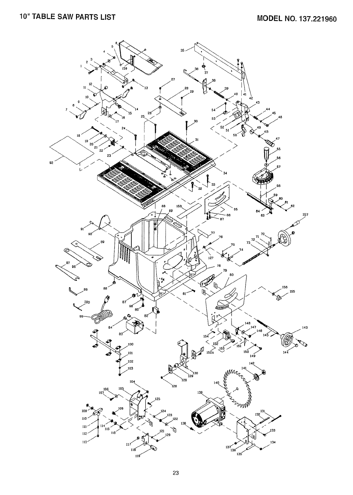
10" TABLE SAW PARTS LIST MODEL NO. t37.221960
5
17
27
142
141
23
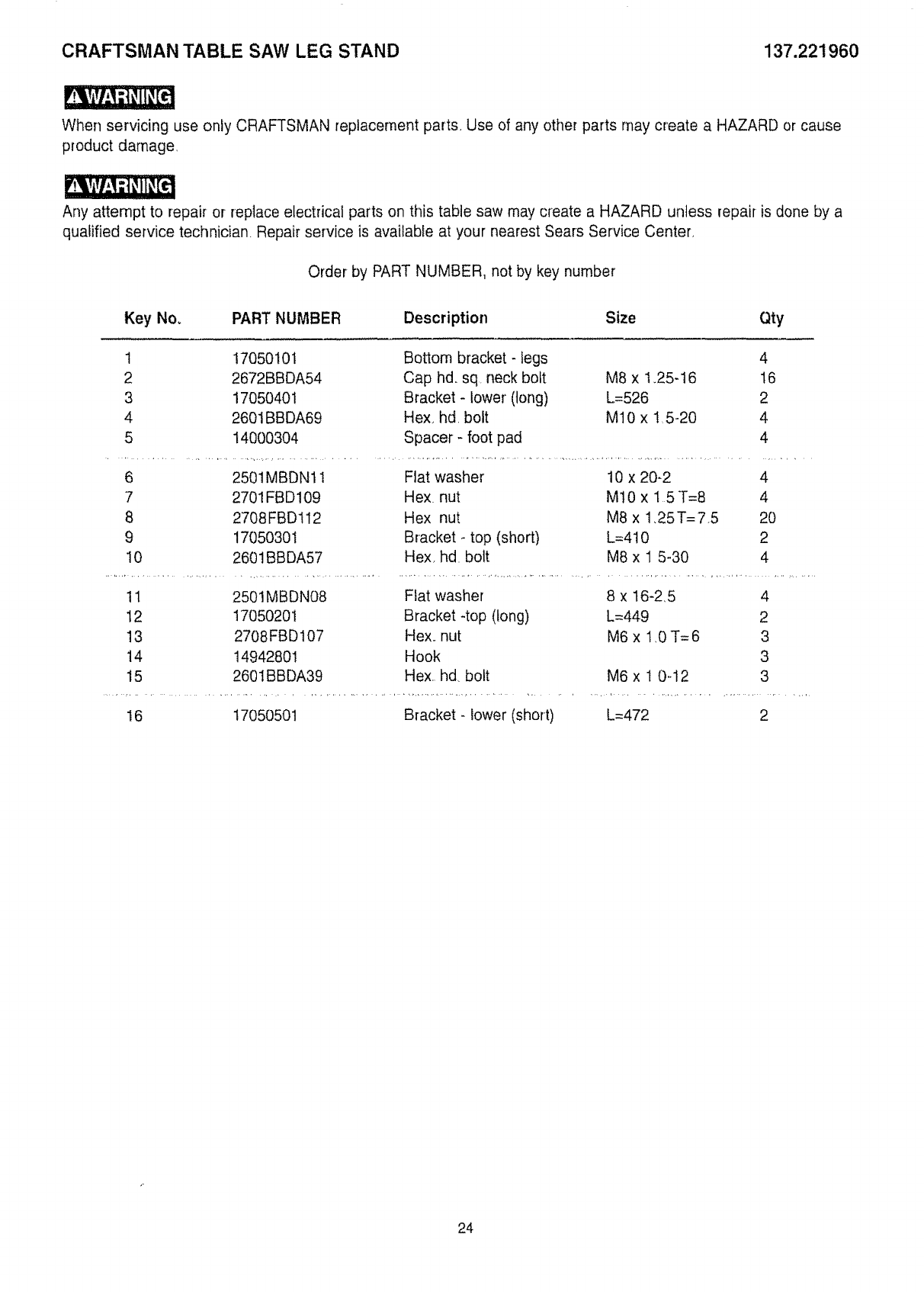
CRAFTSMAN TABLE SAW LEG STAND 137.221960
When servicing use only CRAFTSMAN replacement parts, Use of any other parts may create a HAZARD or cause
product damage,
Any attempt to repair or replace electrical parts on this table saw may create a HAZARD unless repair is done by a
qualified service technician Repair service is available at your nearest Sears Service Center.
Order by PART NUMBER, not by key number
Key No. PART NUMBER Description Size Qty
1 17050101 Bottom bracket - legs 4
2 2672BBDA54 Cap hdo sq neck bolt M8 x 1.25-16 16
3 ! 7050401 Bracket - lower' (tong) L=526 2
4 2601BBDA69 Hex_ hd, bolt Mt0 x ! 5-20 4
5 14000304 Spacer - foot pad 4
6 2501MBDN1 ! Flat washer' 10 x 20-2 4
7 2701FBD109 Hex. nut M10 x 15 T=8 4
8 2708FBD112 Hex nut M8 x 1.25T=75 20
9 1705030I Bracket- top (short) L=4t 0 2
10 2601BBDA57 Hex. hd. bolt M8 x 1 5-30 4
11 2501MBDN08 Flat washer 8 x 16-2.5 4
12 17050201 Bracket -top (tong) L=449 2
13 2708FBD107 Hex_ nut M6 x 1,0 T=6 3
14 14942801 Hook 3
15 2601BBDA39 Hex hd bolt M6 x 1 0o12 3
16 17050501 Bracket - lower (short) L=472 2
24
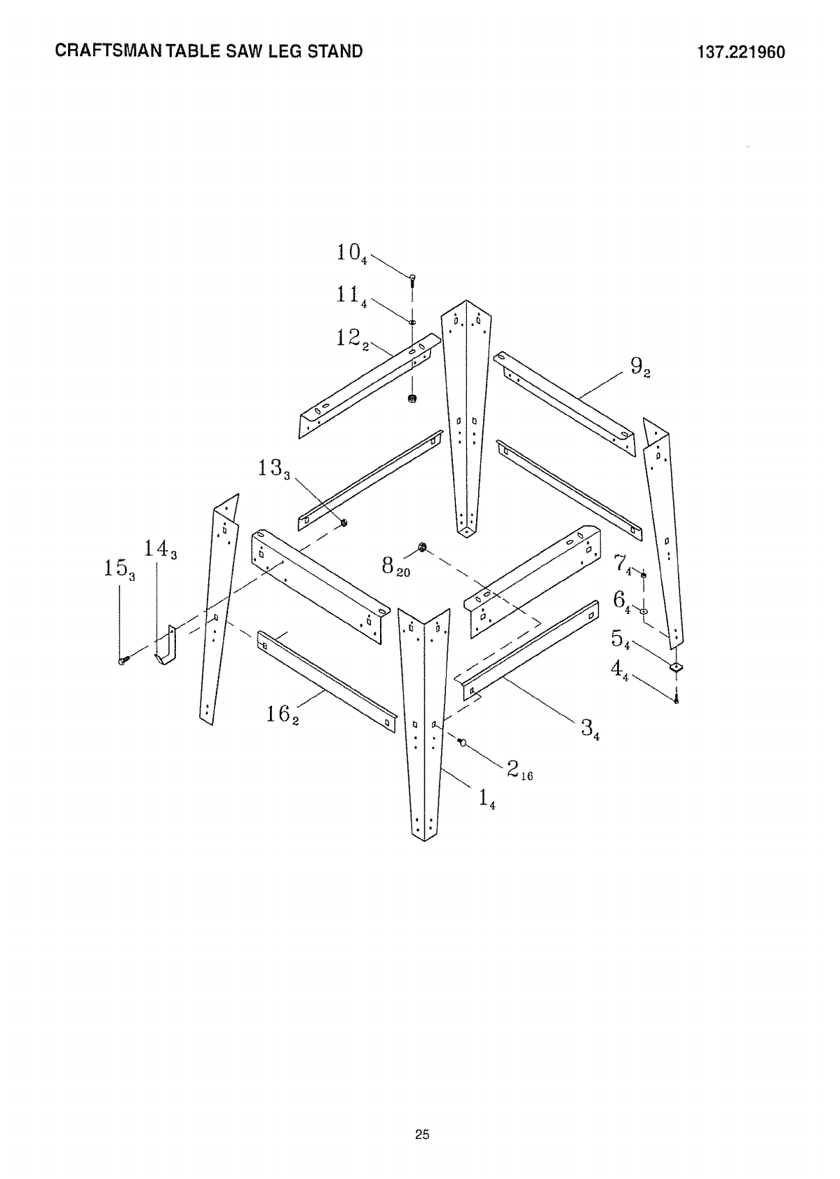
CRAFTSMAN TABLE SAW LEG STAND 137.221960
13_ \
9 2
\
i 4
_16
4
25
i
/
/Oo
0
.£2
26
0
0
r-

27

28
iVlanualde Operaci6n
CRFIFTSM
2.5 HP (Potencia M_xima)
Hoja Circular de
25.4cm (10")
5000 R.P.M.
Modelo No.
137.221960
tO.in.
TABLE SAW
CUIDADO:
Antes de usar esta sierra de mesa,
leer este manual y seguir todas sus
Regtas de Seguridad e Instrucciones
de Operaci6n.
O
• Instruccionesde Seguridad
• Instalaci6n
• Operaci6n
• Mantenimiento
• Lista de Partes
Tel6fono para
Ayuda al Cliente
1-800-843-1682
Sears, Roebuck and Co., Hoffman Estates, IL 60179 USA
Part No. 137221960001
SECCION P,_,GINA
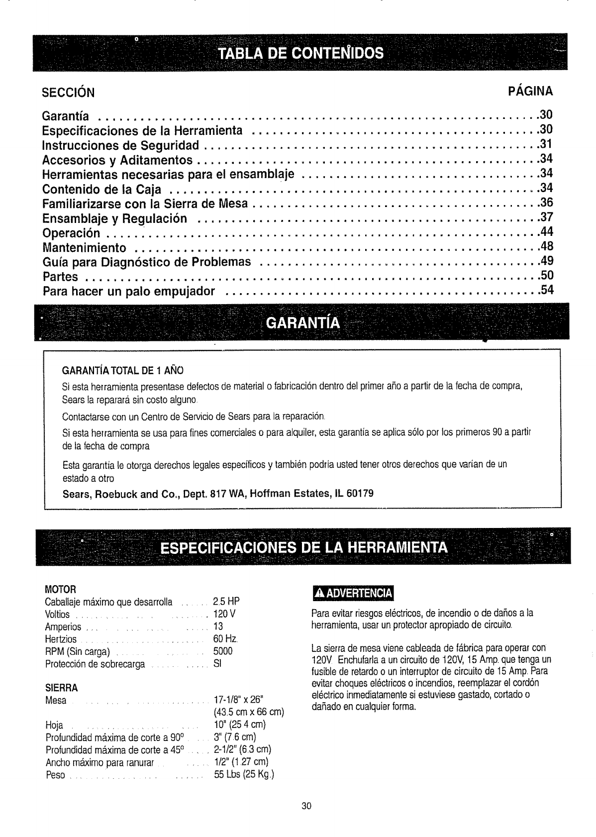
Garantia ................................................................ 30
Especificaciones de la Herramienta .......................................... 30
lnstrucciones de Seguridad ................................................. 31
Accesorios y Aditamentos .................................................. 34
Herramientas necesarias para el ensamblaje ................................... 34
Contenido de la Caja ...................................................... 34
Familiarizarse con la Sierra de Mesa .......................................... 36
Ensamblaje y Regulaci6n .................................................. 37
44
Operaci6n ...............................................................
Mantenimiento ........................................................... 48
Gu/a para Diagn6stico de Probtemas ......................................... 49
Partes .................................................................. 50
Para hacer un palo empujador .............................................. 54
GARANT{ATOTAL DE 1At_O
Siesta herramienta presentase defectosde material o fabdcaci6n dentro de! primeraSoa partir de la fecha de comp_a,
Sears la reparara sin costo alguno.
Contactarse con un Centrode Serviciode Sears para la reparad6n
Siesta herramientase usa para fines comerdales o para alquiler, esta garantia se aplicas6fo per los pfimeros 90 a partir
de la fecha de compra
Estagarantia leotorga derechos legales especfficosy tambien podria ustedtenetotrosderechos que varian de un
estado a otro
Sears, Roebuck and Co., Dept. 817 WA, Hoffrnan Estates, IL 60179
MOTOR
Caballajemaximo que desarrolla ...... 2,5 HP
Voltios .................. 120V
Amperios ................... 13
Hert.zios.......................... 60 Hz
RPM (Sin carga) ................ 5000
Protecci6nde sobrecarga ............ S]
SIERRA
Mesa ....................... !7-t/8" x 26"
(435 crn x 66 crn)
Hoja ......................... 10" (25 4 cm)
Profundidadm&xima de corte a 900 . 3" (76 cm)
Profundidadmaxima de corte a 450 ..... 2-1/2" (6,3 cm)
Ancho m_imo para ranura[ ...... 1/2"(I 27 cm)
Peso ........................ 55 Lbs (25 Kg,)
Paraevitar riesgosel6ctricos,de incendio o de daSosa la
herrarnienta,usar unprotector apropiado de circuitQ.
La sierra de mesaviene cableada de fabrica paraoperarcon
120V Enchufarlaa un circuitode I20V, 15 Amp.que tenga un
fusiblede retardoo un interTuptorde circuito de I5 Amp.Para
evitarchoqueselectdcoso incendios, reemplazarel cord6n
et6ctricoinmediatamentesi estuviese gastado, cortadoo
daSadoen cualquierform&
3O
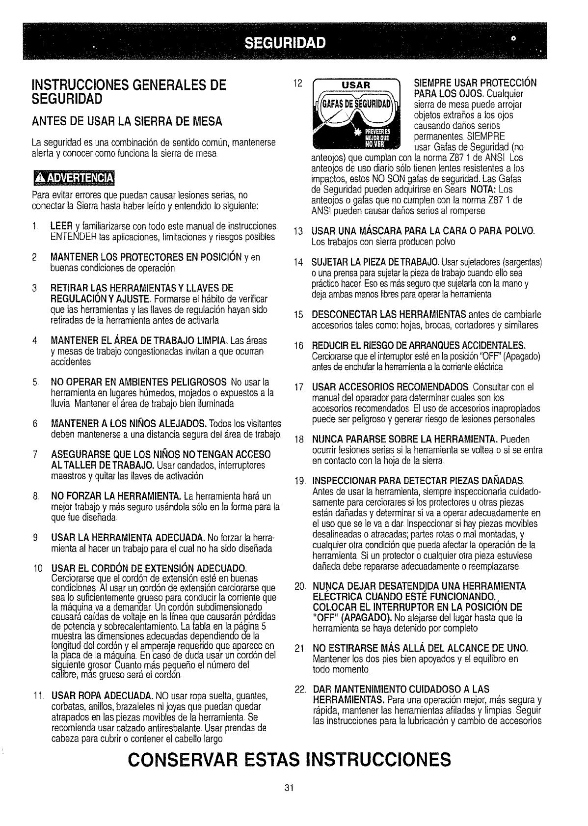
INSTRUCClONESGENERALESDE
SEGURIDAD
ANTES DE USARLA SIERRADE MESA
La seguridad es una combinaciSnde sentidocomun, mantenerse
alerta y conocercomofuncionala sierra de mesa
Paraevitarerroresque puedancausar lesionesserias,no
conectar la Sierrahastahaber leidoy entendido to siguiente:
LEER y familiarizarsecon todo este manual de instrucciones
ENTENDERIasapiicaciones,limitacionesy riesgosposibtes
MANTENERLOS PROTECTORESEN POSlClONy en
buenas condicionesde operaci6n
3RETIRAR LAS HERRAMIENTASY LLAVES DE
REGULACIONYAJUSTE. Formarseel h_bito de verificar
que las herramientasy tasllavesde reguiaciSnhayan sido
retiradasde ta herramientaantesde activarla
4 MANTENER EL _,READETRABAJOLIMPtA_Las _reas
y mesasde trabajocongestionadasinvitan a que ocurran
accidentes
.NO OPERAREN AMBIENTES PELIGROSOS No usarla
herramientaen lugares hOmedos,mojadoso expuestosa la
tluvia Mantenerel &teade trabajo bieniluminada
MANTENERALOS NINOSALEJADOS. Todoslos visitantes
debenmantenersea unadistancia seguradel _reade trabajo
ASEGURARSEQUE LOS NII_OSNOTENGAN ACCESO
AL TALLER DETRABAJO. Usarcandados,interruptores
maestrosy quitar las tlavesde activaci6n
8 NO FORZAR LA HERRAMIENTA.La herramientahar&un
meior trabajoy masseguro us_ndolas6!oen laforma parala
que ruedise_ada
10
USAR LA HERRAMIENTAADECUADA.No forzar la herra-
mientaal hacerun trabajopara el cual no ha sido diseSada
USAR EL CORDONDE EXTENSIONADECUADO.
Cerciorarseque et cord6nde ex%nsi6nest_en buenas
condiciones AI usar un cord6n de extensi6ncerciorarseque
sea Io suficientementegrueso paraconducir lacorrienteque
la m&quinava a demandar Un cord6n subdimensionado
causar_ caidas devoltajeen la lineaque causar_np_rdidas
de potenciay sobrecalentamiento.Latabta en la pagina5
muestra lasdimensionesadecuadasdependiendod-ela
longituddel cord6ny el amperaje requeridoque aparece en
la placa de la m_quina En caso de duda usar un cord6ndel
siguiente.qrosorCuantom&spegueSoel nOmerodel
calibre,m_s gruesosera et cord6n
11 USAR ROPAADECUADA.NO usar ropa suelta,guantes,
corbatas,anifios,brazaletesnijoyasque puedanquedar
atrapadosen las piezasmoviblesde la herramienta Se
recomiendausarcalzadoantiresbatanteUsar prendasde
cabeza paracubrir o contenerel cabellolargo
12
13
14
I5
16
17
18
I9
20
21
22,,
USAR StEMPREUSAR PROTECClON
PARA LOS OJOS.Cualquier
sierrade mesapuedearrojar
obietosextraSosa tosojos
causandodaSosserios
permanentes SIEMPRE
usar Galasde Seguridad(no
anteojos)que cumptancon la normaZ87 1de ANSI Los
anteojos de uso diarios61otienen lentesresistentesa los
impactos,estos NO SONgafasde seguridad.Las Galas
de Seguridadpuedenadquirirseen Sears NOTA:Los
anteojoso gafasque nocumptencon ia norma Z87 1 de
ANS1pueden causardaSosseriosal romperse
USAR UNA MASCARA PARA LA CARA O PARA POLVOo
Los trabajoscon sierra producenpolvo
SUJETARLA PIEZADETRABAJO.Usarsujetadores(sargentas)
o unaprensaparasujetarlapiezadetrabajocuandoeliosea
pr,_clicohacer Esoes masseguroquesujetarlaconla manoy
dejaambasmanosfibresparaoperarlaherramienta
DESCONECTARLAS HERRAMIENTASantesde cambiarle
accesoriostales como: hojas,brocas,cortadores y similares
REDUCIREL RIESGODEARRANQUESACCIDENTALES,
CerciorarsequeelintemJptorest_enlaposici6n"OFF"(Apagado)
antesdeenchufarlaherramientaa lacorrienteel_ctrica
USARACCESORIOSRECOMENDADOSConsultarcon et
manualdel operadorparadeterminarcualesson los
accesoriosrecomendadosEluso de accesoriosinapropiados
puedeser peligrosoy generarriesgode tesionespersonafes
NUNCA PARARSESOBRE LA HERRAMIENTA,Pueden
ocurrir tesionesserias si la herramientase voltea o si se entra
en contactocon la hoja de Ia sierra
INSPECCIONARPARA DETECTARPIEZASDANADAS,
Antesde usar la herramienta,siempreinspeccionarlacuidado-
samenteparacercioraressi Iosprotectoresu otraspiezas
estanda5adasy determinarsiva aoperaradecuadamenteen
el uso que se le va a dar Inspeccionarsi hay piezasmovibies
desalineadaso atracadas;partes rotaso mai montadas,y
cualquierotra condiciSnquepuedaafectarlaoperaci6n de]a
herramientaSi un protectoro cualquierotrapieza estuviese
da5adadeberepararseadecuadamenteo reemplazarse
NUNCA DEJAR DESATENDIDAUNA HERRAMtENTA
ELECTRICA CUANDOESTE FUNClONANDO.,
COLOCAR EL INTERRUPTOREN LA POSIClON DE
"OFF" (APAGADO)oNo alejarse del Iugar hasta que ta
herramienta se haya detenidoporcompleto
NO ESTtRARSE MAS ALL_, DEL ALCANCE DE UNO,
Mantener los dos pies bien apoyadosyet equilibro en
todo momento
DAR MANTENIMIENTOCUIDADOSOALAS
HERRAMtENTAS. Parauna operaci6n mejor, mas segura y
r_,pida,mantener las herramientasafiiadas y limpias Seguir
las instrucciones para la lubricaci6ny cambio de accesorios
CONSERVAR ESTAS INSTRUCClONES
31
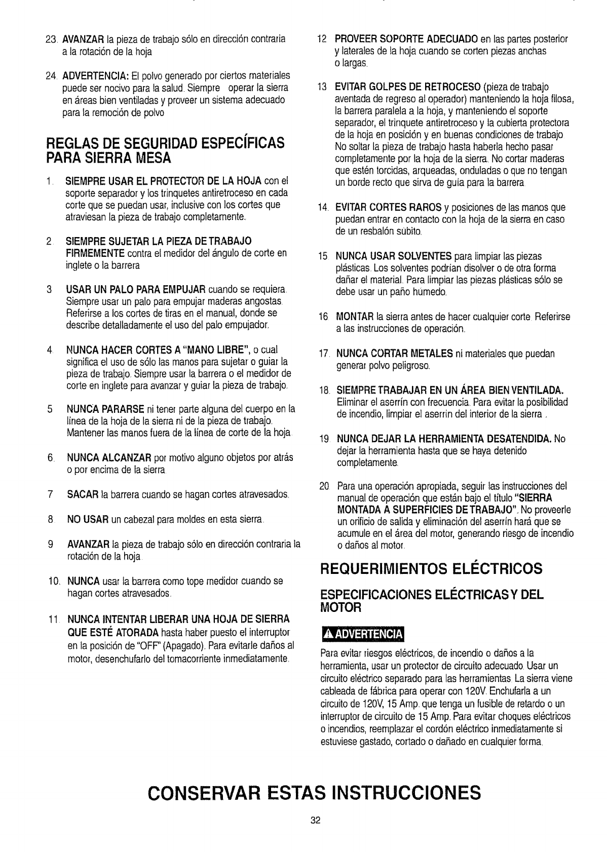
23. AVANZAR la pieza de trabajo s61oen direcci6n contrafia
a la rotaci6nde la hoja
24. ADVERTENCIA: El polvo generado pot ciertos matefiales
puede set nocivo parata salud. Siempre opera[ Ia sierra
en areas bien ventiladasy proveer un sistema adecuado
para la remoci6n de polvo
REGLAS DE SEGURIDADESPECiFICAS
PARA SIERRAMESA
.SIEMPRE USAR EL PROTECTORDE LA HOJA con et
soporte separador y los tfinquetes antiretrocesoen cada
co[to que se puedanusa[, inclusivecon los cortes que
atraviesan la pieza de trabajocompletamente
2 StEMPRE SUJETAR LA PtEZA DETRABAJO
FIRMEMENTEcontra el medidor del _ngulo de corte en
inglete o ta bar[era
USAR UN PALO PARA EMPUJAR cuando se requiera.
Siempre usa[ un palo paraempujar made[as angostas
Refefirse a los cortes detiras en et manual,donde se
describedetaliadamenteel uso del pato empujador_
NUNCA HACER CORTES A "MANO LIBRE", o cual
significa el uso de s61oias manospara sujetar o guial la
pieza de trabajo Siempre usa[ Ia barrera o el medido_de
co[re en ingtetepara avanzary guiar ta pieza de trabajo.
NUNCA PARARSE ni tener parte alguna del cuerpo en ta
tinea de la hoja de la sierrani de la pieza de trabajo
MantenerIas manosfuera de la linea de co[re de la hoja
6 NUNCA ALCANZAR per motivoatguno objetos por at[as
o por encimade la sierra
7 SACAR Ia barreracuando se hagan cortes atravesados.
8 NO USAR un cabezal paramotdes en esta sierra.
9 AVANZAR ta pieza de trabajo s6]o en direcci6ncontraria ta
rotaci6n de ta hoja
10. NUNCA usa[ la barreracomo tope medidot cuando se
hagan cortes atravesados
11 NUNCA INTENTARLIBERAR UNA HOJA DE SIERRA
QUE ESTE ATORADA basrahaber puesto el interruptor
en fa posici6n de "OFF"(Apagado).Para evitafle daSos al
motor,desenchufarlo deltomacorrienteinmediatarnente,
12
13
14.
15
t6
17
18
PROVEERSOPORTE ADECUADO en las partesposterior
y tateralesde ia hoja cuando se corten piezasanchas
o largas.
EVITARGOLPES DE RETROCESO(pieza de trabajo
aventadade regreso at operador) manteniendota hoja filosa,
la bar[era paraletaa la hoja, y manteniendoel soporte
separador,el trinquete antiretrocesoy ta cubiertaprotectora
de la hojaen posici6n y en buenas condicionesde trabajo
No soltarla pieza de trabajo hasta habefla hecho pasar
completamentepor la hoja de la sierra, No cortarmade[as
que est6n torcidas,a[queadas, onduladas o que no tengan
unborde recto que sirra de guia para ia barrera
EVlTARCORTES RAROS y posiciones de las manos que
puedanentrar en contacto con la hoja de Ia sierra en caso
de un resbal6n subito_
NUNCA USAR SOLVENTES para limpiar las piezas
p!_sticas.Los sotventes podfian disolver o de otra forma
daSarei material Paralimpiar las piezas pl_sticass6Iose
debe usa[ un paso h,Jmedo.
MONTARta sierra antes de hacer cualquie_co[re Referirse
a Iasinstruccionesde operaci6n_
NUNCACORTAR METALES ni materiales que puedan
genera[ polvo peiigroso.
SIEMPRETRABAJAR EN UN AREA BEN VENTtLADA,
Eiiminarel aserrin con frecuencia Para evitarla posibilidad
de incendio,limpiat el aserrin del interior de la sierra _
I9 NUNCA DEJAR LA HERRAMtENTA DESATENDIDA,No
dejar ta her_amientahasta que se hayadetenido
completamente,
20 Para unaoperaci6n apropiada, seguir las instruccionesdel
manual de operaci6n que est_n bajo el tituto "SIERRA
MONTADAA SUPERFICIES DETRABAJO". No proveerle
un orificiode satiday eliminaci6ndel aserrin har_que se
acumuleen el _rea del motor, generando riesgode incendio
o daSosat motor.
REQUERIMIENTOS ELI CTRICOS
ESPEClFICAClONES ELI_CTRICASY DEL
MOTOR
Paraevitarriesgoselectricos, de incendio o daSosa la
herramienta,usa[ un protector de circuito adecuado Usar un
circuitoeI_ctricoseparado para las herramientas La sierra viene
cableadade f_bdcapara opera[ con 120V.Enchufarlaa un
circuitode 120V,15Amp. que tenga un fusible de [eta[do o un
interruptorde circuitode 15 Amp. Paraevitar choquesel6ctficos
o incendios,reernptazarel cord6n el_ctrico inmediatamentesi
estuviesegas[ado,codado o da5ado en cuatquierforma.
CONSERVAR ESTAS INSTRUCClONES
32
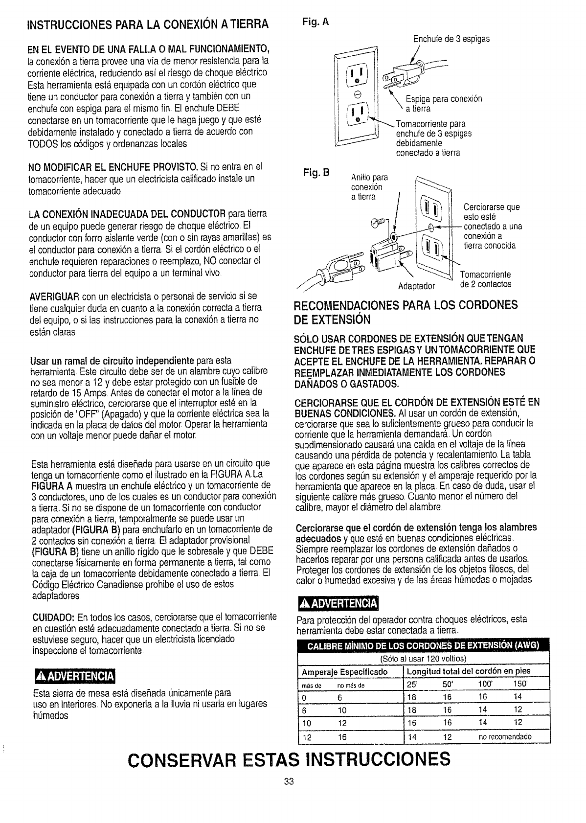
INSTRUCCiONES PARA LA CONEXlON ATtERRA Fig. A
EN EL EVENTODE UNA FALLA O MAL FUNCIONAMIENTO,
laconexi6n a tierra provee una via de menor resistenciapara la
corrienteelectrica, reduciendoasi el riesgo dechoque electrico
Esta herramientaest_ equipada con un cord6n el_ctricoque
tiene un conductor paraconexbn a tierra y tambiencon un
enchufecon espiga parael rnisrnofin. El enchufeDEBE
conectarseen un tomacorriente que le hagajuego y que est_
debidamenteinstafado y conectado a tierra de acuerdo con
TODOS los c6digos y ordenanzas locales
NO MODIFICAREL ENCHUFE PROVlSTO.Si no entra en el
tornacorriente,hacer que un electricista calificadoinstaleun
tornacorrienteadecuado
LA CONEXlON INADECUADA DEL CONDUCTORparatierra
de un equipopuede generarriesgo de choque el_ctrico El
conductor con forro aislanteverde (can o sin rayasamarillas) es
el conductor para conexi6n a tierra Si et cord6n etectricoo el
enchufe requierenreparacioneso reernplazo,NO conectar el
conductor para tierra del equipo a unterminal vivo
AVERIGUARcon un electricista o personal de serviciosi se
tiene cualquier duda en cuanto a la conexi6ncorrecta a tierra
det equipo,o si tas instrucciones para ta conexi6na tierra no
est_n claras
Usar un rama! de circuito independiente paraesta
herrarnienta Este circuito debe set de un alarnbrecuyocalibre
no sea rnenora 12 y debe estar protegido con un fusiblede
retardo de 15Arnps Antesde conectar el motora ta linea de
suministroel6ctrico, cerciorarse que el interruptorest_ en la
posici6nde "OFF" (Apagado)y que la corrienteel_ctrica sea la
indicada en ta ptacade dabs del motor Operar la herramienta
con un voltaje rnenorpuede dafiar el motor,
Esta herramientaest&diseflada para usarseen un circuitoque
tenga un tomacorrientecomo et ilustradoen fa FIGURAALa
FIGURAA rnuestraun enchufe el_ctrico y un tomacorrientede
3 conductores,uno de los cuafes es un conductor paraconexi6n
a tierra.Si no se dispone de un tomacorrientecon conductor
para conexi6na tierra, temporalmentese puede usar un
adaptador (FtGURA B) para enchufarloen un tornacorrientede
2 contactos sin conexi6n a tierra.E! adaptadorprovisional
(FIGURA B) tiene un anillo figido que le sobresaley que DEBE
conectarseffsicarnente en forma perrnanentea tierra,tal como
ta caja de un tomacorriente debidamente conectadoa tierra.El
C6digo EI6ctricoCanadiense prohibeel uso de estos
adaptadores
CUIDADO: En todos los casos, cerciorarseque el tomacorriente
en cuesti6n est_ adecuadamente conectado a tierra Si no se
estuvieseseguro, hacer que un electricista ticenciado
inspeccioneel tomacorriente
Esta sierrade mesa est&diseflada Linicarnentepara
uso en interiores No exponertaa la tluvia ni usafla en Iugares
hSmedos
Enchub de 3espigas
Espigaparaconexi6n
a tierra
_--_Tomacorrientepara
enchufede 3 espigas
debidamente
conectadoa '[ierra
Fig. B Aniltop,ara __..---....._
conexton 1 "----_-'_
/II!ll_l ll Cerciorarseque
Ci._- lI '<-_'_)i[ estoeste
._e"i'_f_ It conexi6na
__ _ !] _'_ If tierra conocida
./'_,'_;!T_ u'_ _ "..... _ Tomacorfiente
/_J'_"-_- Adaptador de2 contactos
RECOMENDAClONESPARA LOS CORDONES
DE EXTENSION
SOLO USAR CORDONESDE EXTENSI(]N QUETENGAN
ENCHUFE DETRES ESPIGASY UNTOMACORRIENTEQUE
ACEPTE EL ENCHUFEDE LA HERRAMtENTA,REPARAR O
REEMPLAZAR tNMEDIATAMENTELOS CORDONES
DAt_ADOS O GASTADOS,
CERClORARSE QUE EL CORDON DE EXTENSI(]N ESTE EN
BUENAS CONDIClONES.AI usar un cord6n de extensi6n,
cerciorarse quesea lo suficienternentegrueso para conducir la
corrienteque la herrarnientademandara Un cord6n
subdirnensionadocausar_una caida en el voltaje de la Iinea
causando una p6rdidade potencia y recatentamiento,La tabla
que aparece en esta p_ginamuestra los calibres correctosde
los cordones seg_n su extensi6n y el amperaje requerido pot la
herramienta que apareceen la placa En caso de duda, usar el
siguiente calibre mas grueso Cuanto rnenorel n_rnerodel
calibre, mayor et di_metrodel alambre
Cerciorarse que el cord6nde extensi6n tenga los alambres
adecuados y que est_en buenas condiciones ei6ctficas,
Siempre reempiazarloscordones de extensi6ndaflados o
hacerlos repararpot una persona calificada antes de usarlos,
Proteger los cordonesde extensi6n de los objetos fi!osos,del
calor o humedadexcesivay de las _,reashSmedaso rnojadas
Para protecci6nde! operadorcontra choques el_ctricos, esta
herramientadebe estar conectada a tierra.
....................... I ,,,I,, _ ii :
R_;! It]:1;I_i L_rjiJ_Jl_'r_[el s,]:diITo].,,."[e,[o];|i[e]_t_1 I] 4 _:i l_ __11_]_lf."_ _i_-I
(S61oai usar 120 voltios)
Amperaje Especificado Longitud total del cord6n en pies
m_sde n_m_de 25' 50' I00' 150'
0 6 18 16 16 !4
6 10 !8 16 14 12
10 12 16 16 14 I2
12 16 !4 12 no recomendado
CONSERVAR ESTAS INSTRUCClONES
33
ACCESORIOS RECOMENDADOS
En esta sierra no sedebe usar hojas ranuradorasde tipo
regulable ni hojas con dientes de carburo.El ancho m_ximo para
ranurares 127ram (1/2").No usarhojas ranuradorasde m_.sde
1524cm (6"), Con esta sierratampoco se puede usar cabezaies
para mofduras
Visitar el Departamentode Ferretefia de la tienda Sears mas
cercana over el Cat_Jogode Herramientas El6ctricas!Neumaticas
y Manualesde Seam paracomprar los accesofios recomendados
para esta herramienta
Para evitarriesgosde tesionespersonales, no modificaresta
herramientani usaraccesoriosno recomendados por Sears
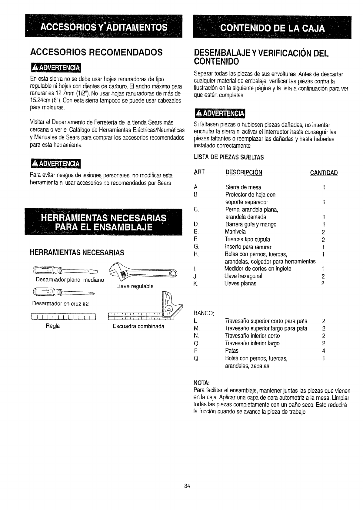
HERRAMIENTASNECESARIAS
Desarmador plano mediano
Desarmador en cruz #2
I I _ I t I I I t,!,,l !_.__
Regla
Uave regulabie
Escuadra combinada
DESEMBALAJEYVERIFICACIONDEL
CONTENIDO
Separar todas las piezas de sus envolturas.Antesde descartar
cualquier materiatde embalaje,verificar tas piezascontra la
ilustraci6n en la siguiente paginay la lista a continuaci6n paravet
que esten completas
Si faltasen piezas o hubiesen piezas daSadas, no intentar
enchufar la sierra ni activarel interruptorhasta conseguir ias
piezas faltanteso reemplazarlas daSadasy hastahabeflas
instalado correctamente
LISTA DE PtEZASSUELTAS
AR_.__T_T DESCRIPCION CANTIDAD
A Sierra de mesa 1
B Protectorde hoja con
soporte separador 1
C, Pemo,arandetaplan&
arandeladentada 1
D Barreragufa y mango 1
E Manivela 2
E Tuercasfipocopula 2
G Inserto para ranurar 1
H, Bolsa con pemos, tuercas, 1
arandelas, colgador paraherramientas
I. Medidorde corles en inglete 1
J Llave hexagonal 2
K Uaves planas 2
BANCO:
L
M
N.
O
P
Q
Travesa5osuperior corto para pata 2
Travesa5osuperior largopara pata 2
TravesaRoinferiorcorto 2
TravesaSoinferiorlargo 2
Patas 4
Bolsa con pernos,tuercas, 1
arandelas,zapalas
NOTA:
Parafacilitarel ensamblaje,mantenerjuntaslas piezas que vienen
en la caja Aplicar una capa de cera automotriz a la mesa. Limpiar
todas las piezas completamentecon un paso seco Esto reducir_.
la fricci6n cuando se avancela pieza de trabajo.
34
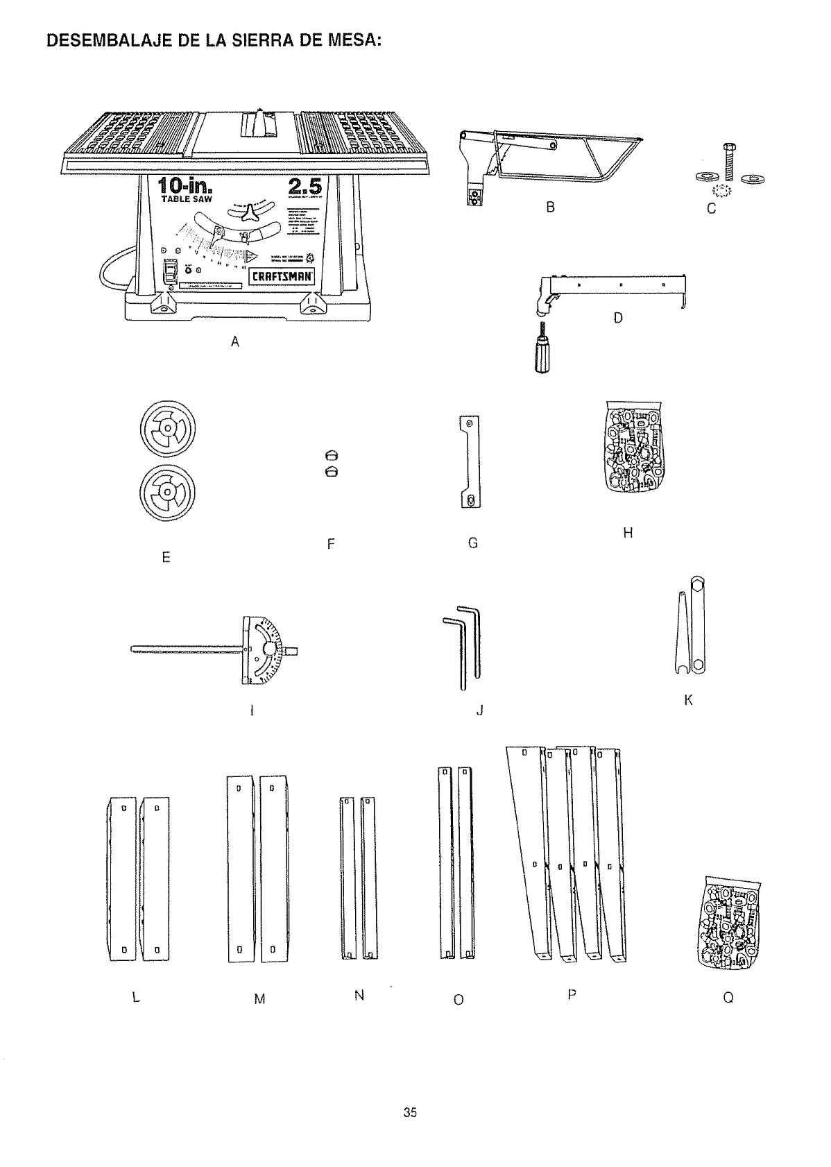
DESEMBALAJE DE LA SIERRA DE MESA:
iO-in. 2.5/tl tl
A
D
C
E
61
G
J
H
oI
o!
L
0
o
O
MN0
0 0 0
©
35
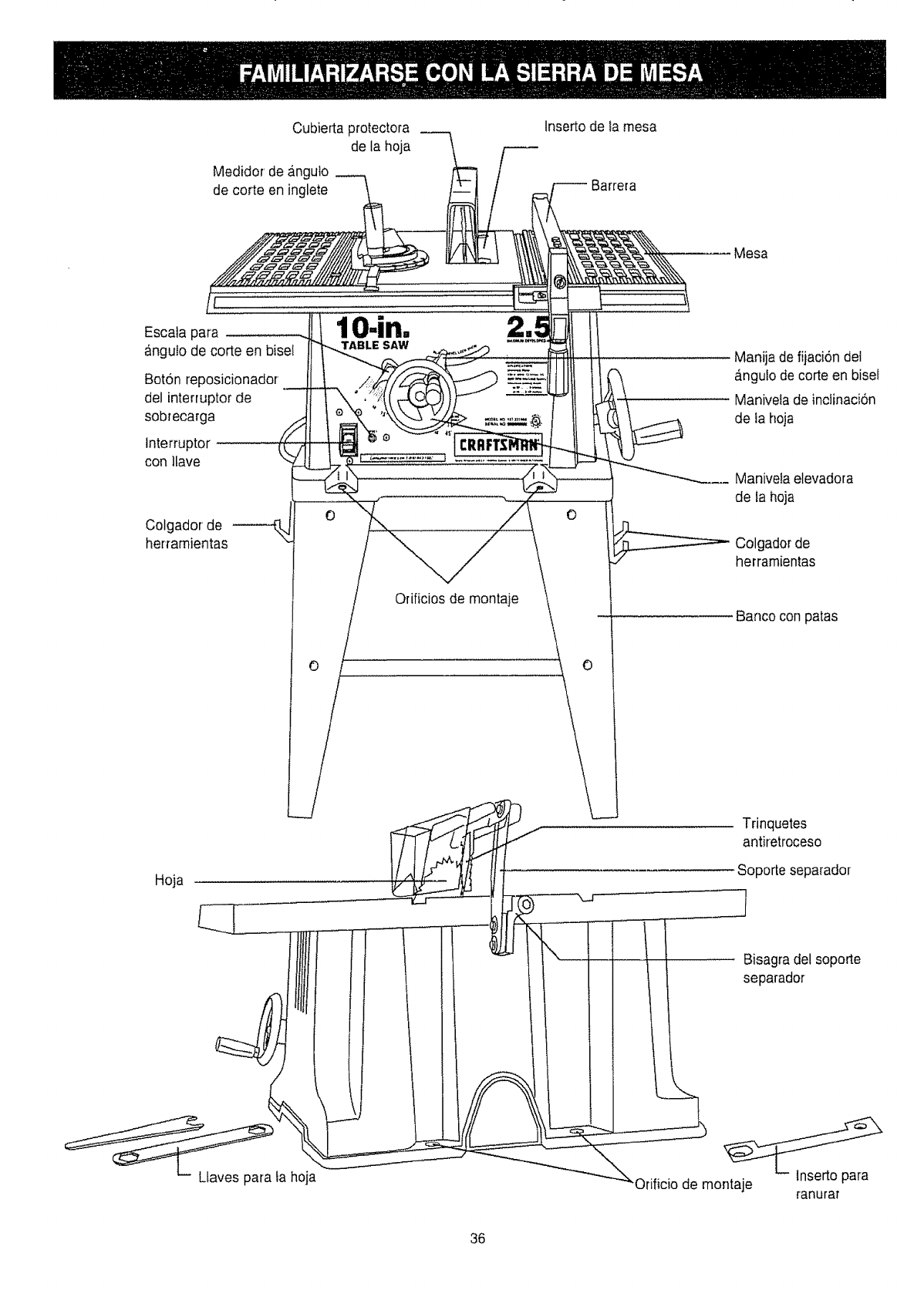
Cubierta protectora
de la hoja
Medidor de anguto
de corte en inglete
Insertode Ia mesa
Barrera
Escata para
angulo de corte en bisel
Bot6n reposicionador
del interruptor de
sobrecarga
lnterruptor
con ltave
lO.in.
TABLE SAW
Colgador de
her_amientas
0
Orificios de montaje
0
Mesa
Manija de fijacion del
anguto de corte en bisel
Maniveta de inelinaci6n
de la hoja
Manivela elevadora
de ta hoja
Colgador de
herramientas
Banco con patas
Trinquetes
antiretroceso
Soporte separador
36
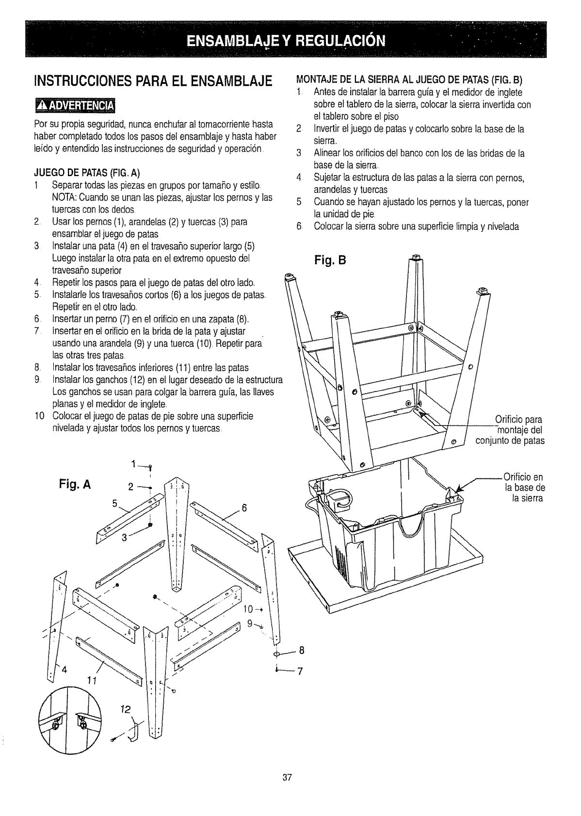
INSTRUCCIONESPARAEL ENSAMBLAJE
For su propia seguridad,nunca enchufarat tomacorrientehasta
haber completado todoslos pasosdel ensambiajey hasta haber
feido y entendidolas instruccionesde seguridad y operaci6n
JUEGO DE PATAS(FIG,A)
! Separar todas las piezasen grupos por tamaRoy estilo
NOTA:Cuando se unanIas piezas, ajustar los pernosy las
tuercas con los dedos
2. Usar los pernos (!), arandetas(2) y tuercas (3) para
ensamblar eljuego de paras
3 lnstalar una pata (4) en et travesaflo superior largo (5)
Luego instalarla otra pata en el extremo opuestodel
travesa5o superior
4. Repetirlos pasos parael juego de paras del otto fadoo
5 lnstalarle los travesaSoscortos (6) a los juegos de paras.
Repetiren el otto lado.
6. lnsertar un perno (7) en elorificio en una zapata (8).
7. lnsertar en el orificioen ta brida de la pata y ajustar
usando una arandela(9) y una tuerca (10).Repetirpara
las otras tres patas.
8. lnstalar los travesaSosinferiores(11)entre las paras
9. Instatarlos ganchos (t2) en el lugardeseado de ta estructura
Los ganchosse usan para colgar la barreraguia, lasllaves
planas y el medidor de inglete.
10 Colocar eljuegode parasde pie sobre una superficie
nivelada y ajustartodos los pernos y tuercas.
MONTAJEDE LA SIERRA AL JUEGO DE PATAS(FIG. B)
1. Antes de instalarla barreraguiay el medidor de ingtete
sobre el tablerode la sierra,colocarla sierra invertida con
el tablero sobre el piso
2 Invertirel juego de patas y co]ocarlosobre la base de la
sierra°
3 Alinear los orificios del banco con los de las bridas de la
base de la sierra.
4 Sujetar ta estructurade tas parasa la sierra con pernos,
arandetasy tuercas
5 Cuando se hayan ajustadolos pernosy la tuercas, poner
la unidadde pie.
6 Colocar la sierra sobre unasuperficie fimpiay nivelada
Fig. B
Orificio para
montaje del
conjunto de patas
el]
ia base de
ta sierra
11
37
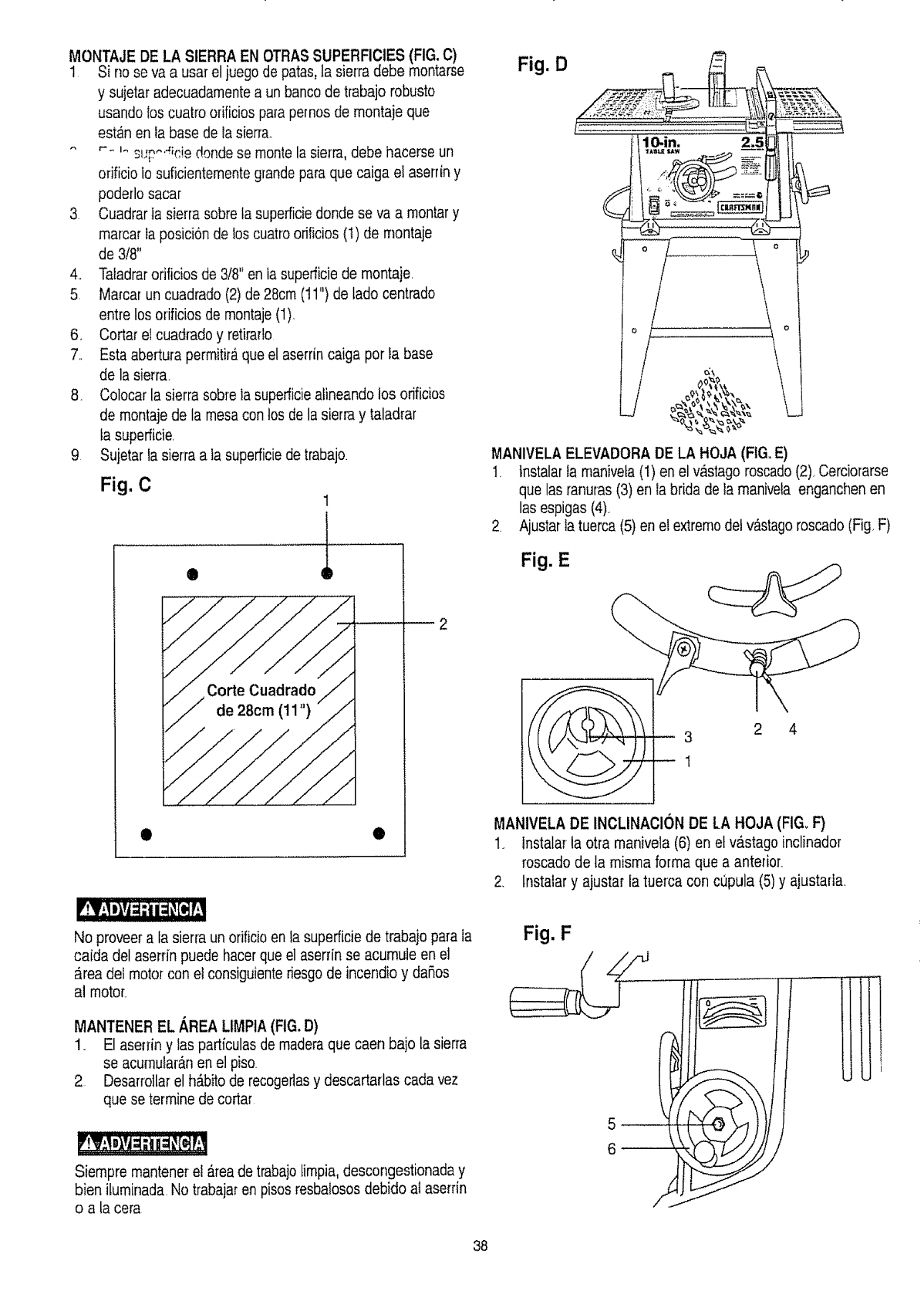
MONTAJE DE LA SIERRA EN OTRAS SUPERFICIES(FIG. C)
1 Si no se va a usar el juego de patas,la sierra debe montarse
y sujetar adecuadamentea un banco de trabajo robusto
usando los cuatro orificios para pernos de montaje que
est_n en la base de lasierra..
,'-_,___,,-,_,m_,..... o donde se monte la sierra,debe hacerse un
orificio lo suficientementegrandepara que caiga et aserrin y
poderlo sacar
3 Cuadrar la sierra sobre ta superficb donde se va a montar y
marcar ia posicion de los cuatroorificios (1) de rnontaje
de 3/8"
4., Taladrarorificios de 3/8" en ia superficiede montaje.
5 Mamar un cuadrado (2) de28cm (t 1") de lado centrado
entre los orificios de montaje(1).
6. Cortar eI cuadrado y retirarfo
7.. Esta abertura permitir_,que el aserrin caiga por ta base
de la sierra.
8. Colocar la sierra sobre la superficieatineando los orificios
de montaje de la mesacon los de la sierra y taladrar
ta superficie.
9 Sujetar fa sierra a ta superficiede trabajo.
Fig. C
®
1
t
e
Fig. D
MANIVELAELEVADORA DE LA HOJA (FIGoE)
I_ Instalar la manivela (1) en el vastago roscado(2)_Cerciomrse
que las mnuras (3) en la brida de ta manivefa enganchen en
las espigas (4)_
2 Ajustarla tuerca (5) en et extrernodel vastago roscado(Fig F)
Fig. E
3 2 4
1
MANIVELA DE INCLINACI(SNDE LA HOJA (FIG=F)
1. Instalar la otra manivela (6) en et v&stago inclinador
roscado de la misma forma que a anterior.
2. Instalar y ajustar la tuerca con cupula (5) y ajustarla.
'!I;I m_,Yj=:ii;!Old!
No proveer a la sierra un orificioen la superficie de trabajopara la
caida del aserrin puede hacer que el aserrin se acumuie en el
area del motor con e! consiguiente riesgode incendio y dafios
al motor_
MANTENER EL AREA LtMPtA(FIG. D)
1_ El aserrin y las particulas de madera que caen bajo la sierra
se acumutaranen el pisQ
2 Desarrollar el h_bito de recogertasy descartarlas carla vez
que se termine de cortar
Siempre mantenerel a.reade trabajolimpia,descongestionaday
bien iluminada. No tmbajar en pisosresbaiosos debido ai aserrin
o a la cera
Fig. F.......li'
5
6
38
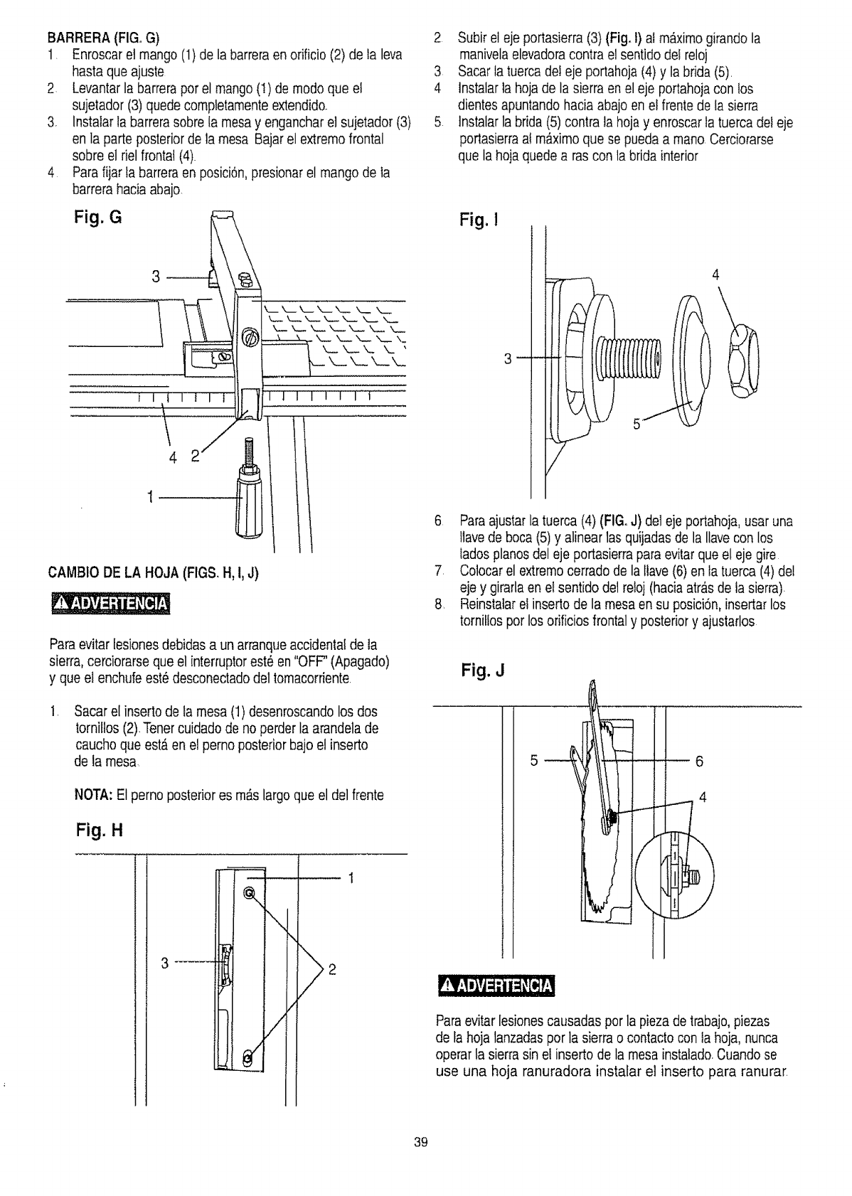
BARRERA (FIG, G)
1. Enroscarel mango (1) de la barreraen orificio (2) de la leva
hasta que ajuste
2 Levantarla barrerapot el mango (I) de modo que el
sujetador (3)quede completamenteextendido.
3. instalar la barrerasobre Ia mesay engancharei sujetador (3)
en la parte posterior de la mesa Bajarel extremo frontal
sobre el riel frontal (4).
4 Para fijar la barrera en posici6n,presionar el mango de la
barrera hacia abajo.
Fig. G
2 Subir el eje portasierra (3) (Fig. t) al m__ximogirando la
manivelaelevadoracontra el sentidodel reloj
3 Sacar ia tuerca deleje portahoja (4) y la brida (5).
4 lnstalarla hojade la sierra en el eje portahoja con los
dientes apuntando hacia abajo en el frentede la sierra
5 tnstalarla brida (5)contra la hojay enroscar la tuerca del eje
portasierraal m_ximo que se pueda a mano.Cerciorarse
que la hoia quede a ras con la brida interior
Fig. !
4
I I I t
CAMBIO DE LA HOJA (FIGS. H, 1,J)
Paraevitarlesiones debidas a un arranqueaccidental de la
sierra, cerciorarse que el interruptorest_ en"OFF' (Apagado)
y que el enchufeest_ desconectadodel tomacorriente
.Sacar el inserto de ta mesa (1)desenroscando los dos
tornillos(2).Tener cuidado de no perder la arandela de
caucho que est_ en el perno posteriorbajo el inserto
de la mesa.
NOTA: El perno posterior es m&s largoque el del frente
Fig. H
,, q
\
/
,
4
.
8,
Paraajustar la tuerca(4) (FIG. J) del eje portahoja, usar una
llavede boca (5) y alinear 1asquijadas de la Ilavecon los
lados pianos del eje portasierrapara evitarque el eje gire
Colocarel extremocerrado de la llave (6) en la tuerca (4)de!
eje y girarlaen el sentido de1retoj (hacia atr&sde la sierra).
Reinstalar el inserto de Ia mesaen su posici6n,insertar los
tornitlospot los orificios frontal y posteriory ajustarlos
Fig. J
5_ m _ 6
_II
Paraevitar lesionescausadas por la pieza de trabajo,piezas
de fa hoja tanzadaspor la sierra o contacto con Ia hoja, nunca
operar ta sierra sin el inserto de la mesa instalado.Cuando se
use una hoja ranuradora instafar el inserto para ranurar.
39
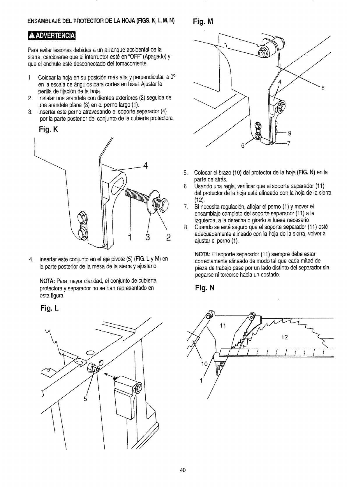
ENSAMBLAJEDEL PROTECTORDE LAHOJA(FIGS.K, L,M,N)
Paraevitartesiones debidas a un ar_anqueaccidenta!de la
sierra, cerciorarseque el interruptorest_ en"OFF" (Apagado)y
que el enchufeest6 desconectadodel tomacorriente.
1 CoIocar la hoja en su posici6n mas alta y perpendicuiar,a 0°
en la escalade _ngulos para cortes en biseLAjustar {a
perilla de fijaciSnde la hoja.
2. Instalaruna arandela con dientes exleriores (2)seguida de
una arandelaplana (3) en e! pemo largo (1).
3. lnsertareste pemo atravesandoel soporte separador (4)
pot la parte posterior del conjunto de la cubie_taprotectora.
Fig. K
Fig. M
,
4
1 3 2
tnsertar este conjuntoen el eje pivote(5) (FIG.L y M) en
ta parte posteriorde la mesa de la sierra y ajustarlo
NOTA:Paramayor daridad, el conjunto de cubierta
protectoray separador no se ban representadoen
esta figura
Fig. L
5. Colocar el brazo (10)deI protector de fa hoja (FIG, N) en la
parte de atr_s.
6 Usando una regta, verificarque el soporte separador (1I)
det protectorde ta hoja est_alineado con la hoja de la sierra
(12).
7. Si necesita regulaci6n,aflojar el pemo (1) y moveret
ensamblajecompleto del soporte separador (11)a ta
izquierda,a la derecha o girarlosi fuese necesario.
8 Cuando se est_ seguroque e! soporte separador (I t) est_
adecuadamentealineadocon la hojade ta sierra,vo]vera
ajustar el perno (1).
NOTA: Elsoporte separador (I i) siempre debe estar
correctamenteatineadode modo taIque cada mitad de
pieza de trabajo pase pot un lado distinto del separadorsin
pegarse ni torcersehacia un costado.
Fig. N
1/
/! "/ / t//1l....l............!
4O
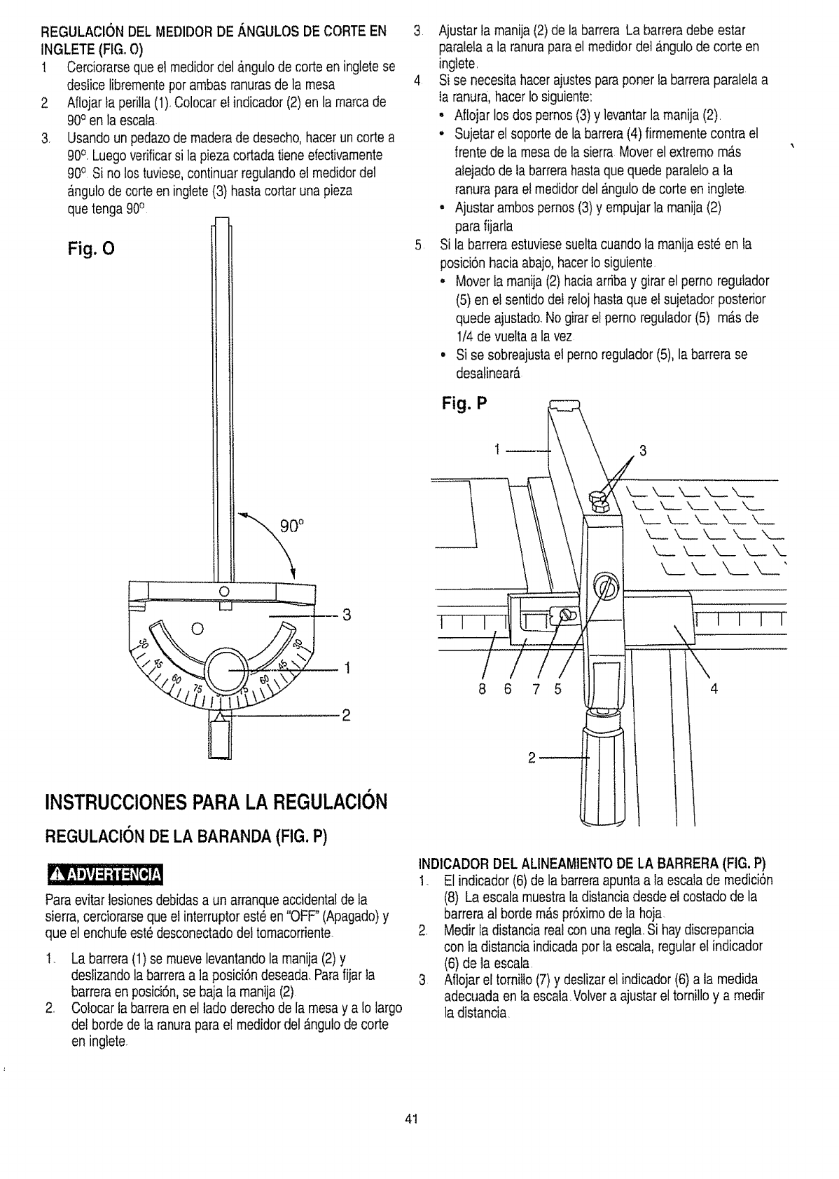
REGULACION DEL MEDIDORDE ANGULOS DE CORTE EN
INGLETE (FIG, O)
1 Cerciorarse que el medidor del angulo de corte en inglete se
destice librementepor ambas ranuras de la mesa
2 Aflojar ta perilla (1).Colocar et indicador (2) en la marcade
90o en la escata
3+ Usando un pedazode madera de desecho, hacer un corte a
90°, Luegoverificarsi la pieza cortada tiene efectivamente
90° Si no los tuviese,continuar regulandoel medidordel
angulo de corte en inglete (3) basracortar una pieza
que tenga 90°
Fig. 0
3
2
INSTRUCCIONESPARALA REGULACION
REGULACIONDE LA BARANDA(FIG. P)
Para evitar lesiones debidas a un arranqueaccidental de la
sierra, cerciorarse queel interruptorest_ en "OFF" (Apagado)y
que el enchufe est_desconectadodet tomacorriente.
t. La barrera (1) se muevelevantandola manija (2) y
deslizandola barreraa la posici6n deseada.Parafijar la
barrera en posici6n,se baja la manija (2)
2. Co!ocar la barreraen el lado derecho de la mesa y a fo largo
del borde de ta ranurapara el medidordel _nguto de corte
en ingtete.
3 Ajustar ta manija (2) de labarrera La barreradebe estar
paratetaa la ranurapara el medidor del angulode corte en
ingtete.
4 Si se necesita hacerajustes para poner ta barrera paralela a
Ia ranura, hacer Io siguiente:
• Aflojar los dos pernos (3)y levantar la manija (2).
• Sujetar el soporte de la barrera(4) firmementecontra el
frente de la mesa de la sierra Moverel extremo mas
atejado de la barrerahastaque quede paraletoa la
ranura para el medidordel #,ngulode corte en inglete
• Ajustar ambos pernos (3) y empujar Ia manija (2)
para fijarla
5 Si la barreraestuviesesueltacuando la manija este en la
posici6n hacia abajo, hacerto siguiente.
° Mover la manija (2) hacia arribay girarel perno reguiador
(5) en el sentidodet relojhasta que et sujetador posterior
quede ajustado.No girarel perno regulador(5) m_s de
1/4 de vuelta a la vez
• Si se sobreajustael perno regulador(5), la barrera se
desalinear&
Fig. P I
8 6 7 5
Z
_ ___ k__ k__ x__ x_._
L_. ___ X__ X__ X_
<
\4
INDICADOR DEL ALINEAMIENTODE LA BARRERA (FIG. P)
t. El indicador (6)de la barreraapunta a la escata de medici6n
(8) La escala muestra Iadistancia desde el costado de la
barreraal borde m_s prSximode la hoja
2. Medir la distancia realcon una regla.Si hay discrepancia
con la distancia indicadapor la escala, regularel indicador
(6) de la escala
3 Aflojar et tornillo (7) y deslizarel indicador (6) a ia medida
adecuada en la escala.Volvera ajustar el tornillo y a medir
la distancia
41
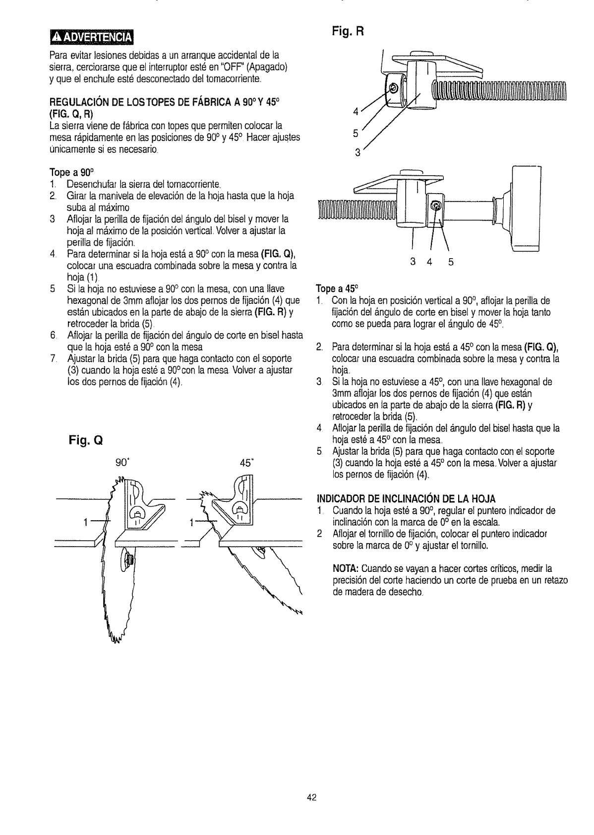
Para evitar lesiones debidas a un arranqueaccidental de la
sierra, cerciorarse que el interruptorest_ en "OFF" (Apagado)
y que el enchufe este desconectadodel tomacorriente..
REGULAClON DE LOSTOPES DE FABRICA A 900Y 450
(FIG. Q, R)
La sierra viene de f_brica con topesque permitencolocar la
mesa rapidarnenteen las posiciones de 90oy 450 Hacer ajustes
unicamente si es necesario
Tope a 900
1. Desenchufar la sierra del tornacorriente.
2. Girar ta rnanivela de elevaci6nde ta hoja hasta que la hoja
suba al m_irno
3 Aftojar la perifla de fijaci6ndel angulo del biseI y mover ta
hoja al m_xirnode la posiei6nvertical Volver a ajustar la
perilla de fijaci6n.
4 Para deterrninar si la hoja est,, a 900con ta mesa (FIG, Q),
colocar una escuadra combinadasobre la mesa y contra la
hoja (t)
5 Si la hoja no estuviesea 900con la mesa, con una llave
hexagonal de 3rnm aflojar los dos pemos de fijaci6n (4) que
est_.nubicados en fa parte de abajode la sierra (FIG. R) y
retroceder ta brida (5)
6. Aflojar ta perilla de fijaciondel _nguto de corte en bisel hasta
que la hoja est_ a 900con la mesa
7 Ajustar la brida (5) paraque haga contactocon el soporte
(3) cuando la hoja est6 a 90°con la mesa Voivera ajustar
los dos pernos de fijaci6n (4).
Fig. Q
90 °45 °
Fig. R
4
5
3
3 4 5
Tope a 45o
1= Con ta hojaen posici6nvertical a 90°, af!ojarta perilIa de
fijaci6ndel _ngulo de corte en bisel y moverla hoja tante
como se puedapara lograr el _.ngulode 450
2_ Paradeterminarsi la hoja est,. a 450con ta mesa(FIG. Q),
colocar unaescuadra cornbinada sobre la mesay contra la
hoja.
3 Si la hojano estuviese a 45°, con una Ilavehexagonal de
3mm aflojar los dos pernos de fijaciSn(4) que estan
ubicadosen la parte de abajo de la sierra (FIG,R) y
retrocederla brida (5).
4 Aflojar ]aperilla de fijaci6n del _.ngulodet biselbasra que ta
hojaest6 a 450con ta mesa.
5 Ajustarla brida (5) para que haga contacto con el soporte
(3) cuandola hoja est_ a 45° con la mesa, Volvera ajustar
los pernos de fijaci6n (4).
INDtCADORDE INCLINACION DE LA HOJA
1: Cuando la hoja est_ a 90°, regular el punteroindicador de
inclinaci6ncon la marca de 0° en la escala.
2 Aflojar el tomiffode fijaci6n, colocar el puntero indicador
sobre la marca de 0° y ajustar el tornilfo.
NOTA: Cuandose vayan a hacer cortes criticos,rnedir la
precisi6ndel corte haciendo un corte de pruebaen un retazo
de madera de desecho
42
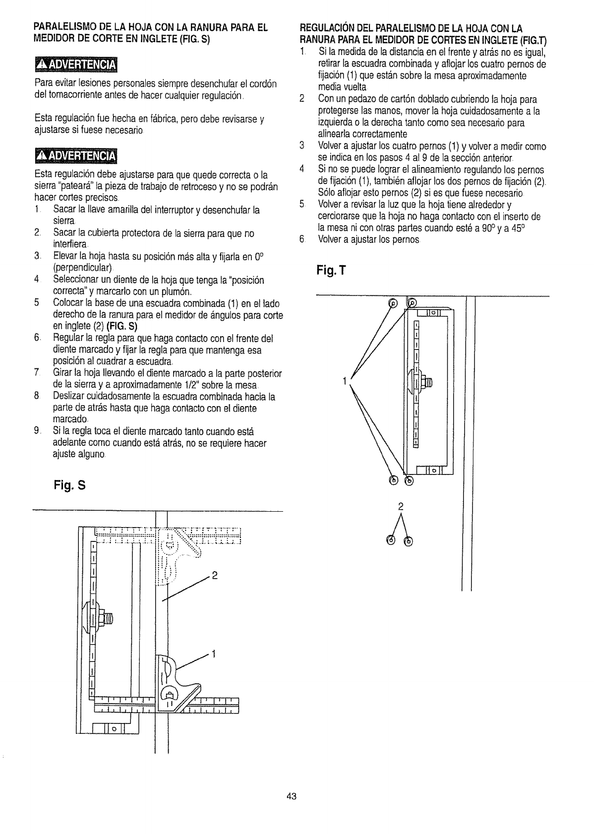
PARALELISMODE LA HOJA CON LA RANURAPARA EL
MEDIDOR DE CORTE EN INGLETE(FIGoS)
Paraevitar Iesiones personalessiempredesenchufarel cord6n
del tomacorrienteantes de hacer cualquierregulaci6n.
Esta regulaci6nrue hecha en fAbdca,perodebe revisarse y
ajustarse si fuese necesario
Esta regulaci6ndebe ajustarse paraque quede correcta o la
sierra "patear&"la pieza de trabajo de retroceso y no se podr&n
hacer cortes precisos.
!. Sacar la ilave amaritla del interruptory desenchufar la
sierra.
2. Sacar fa cubierta protectorade la sierra paraque no
interfiera.
3. Etevarfa hoja has|a su posici6nm_s alta y fijarla en 0°
(perpendicular)
4 Seleccionarun diente de la hojaque tenga la"posici6n
correcta" y marcarlo con un plum6n..
5 Colocar la base de una escuadracombinada(I) en el lado
derecho de la ranurapara el medidorde _ngulos para torte
en inglete (2) (FIG. S)
6 Regular la regla para que haga contactocon el frente de!
diente marcado y fijar la regla paraque mantengaesa
posici6n al cuadrar a escuadra.
7 Girar la hoja Ilevandoel diente marcadoa la parte posterior
de Ia sierra y a aproximadamente1/2"sobrela mesa.
8 Deslizarcuidadosamenteta escuadracombinadahacia la
parte de atr_s hastaque hagacontactocon el diente
marcado.
9. S}la regla toca e! diente marcadotantocuando est,.
adelante como cuando est,. atras,no se requiere hacer
ajustealguno.
REGULAClONDELPARALEL1SMODE LA HOJACONLA
RANURAPARAEL MEDIDORDE CORTESEN INGLETE(FIG,T)
1. Si fa medida de la distancia en el frente y atr_sno es igual,
retirarla escuadracombinada y aftojar los cuatro pernos de
fijaci6n(1) que estan sobre ta mesa aproximadamente
mediavuelta
2 Con un pedazode cart6n dobladocubriendo la hoja para
protegerselas manos, mover la hoja cuidadosamentea la
izquierdao la derecha tanto como sea necesariopara
alineartacorrectamente
3 Volvera ajustar los cuatro pernos (1) y volvera medir como
se indica en los pasos 4 al 9 de la secci6n anterior.
4 Si nose puede lograr el afineamiento regutandolos pemos
de fijaci6n(1), tambien aflojar los dos pemosde fijaci6n (2).
$61oaflojar estopernos (2) si es que fuese necesario
5 Volvera revisarla luz que la hojatiene alrededory
cerciorarseque la hoja no haga contactocon el inserto de
Ia mesani con otras pades cuando est6 a 90oy a 45o
6 Volvera ajustar los pernos
Fig.T
Fig. S
43
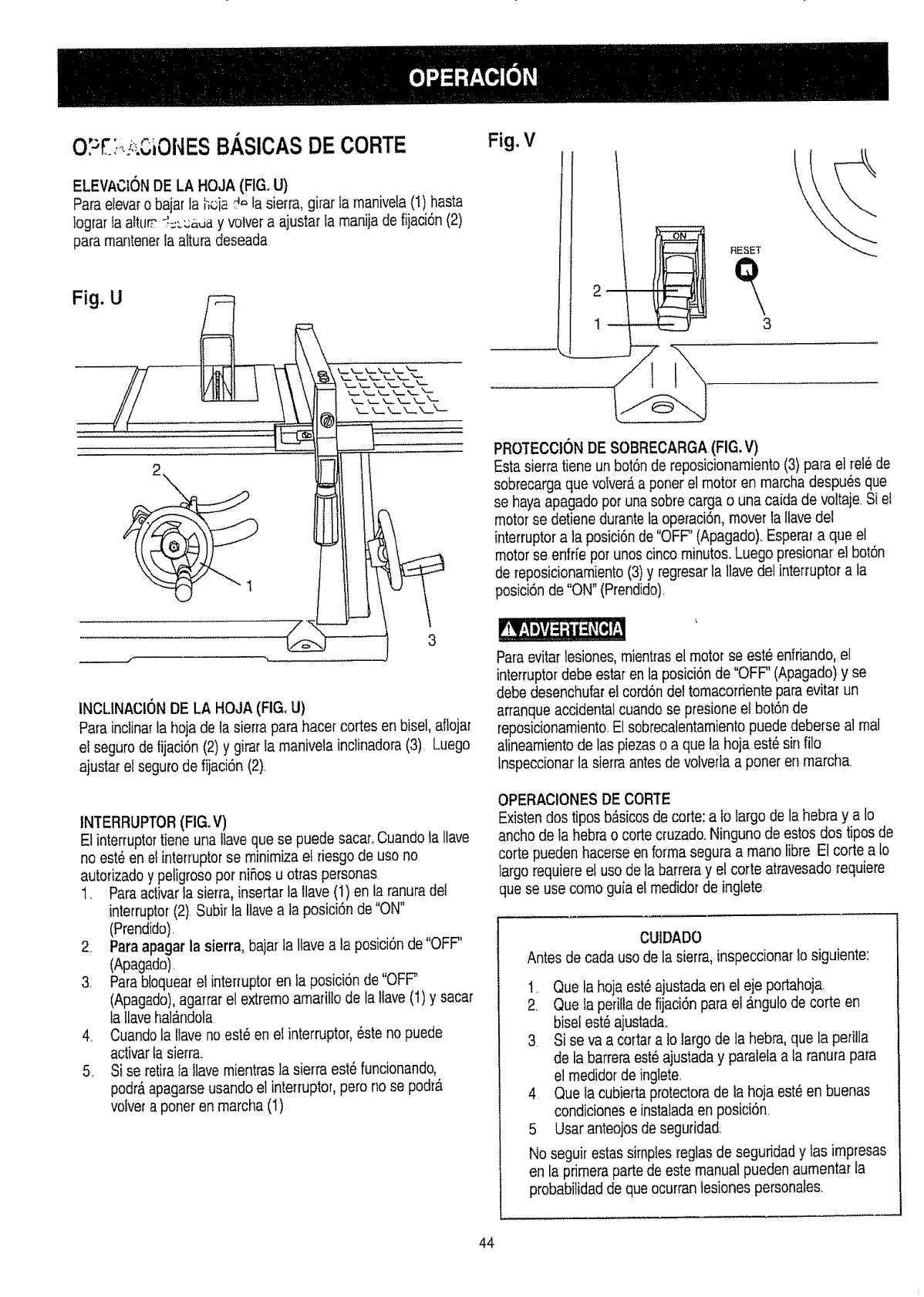
O;;£;, ,j OiOlqESBASICASDE CORTE
ELEVACIONDE LA HOJA (FIG, U)
Para elevaro bajar la l';oia:4,=la sierra, girar fa maniveta(1) hasta
lograr Ia altum :'.:_-;;_,uay votver a ajustar fa manija de fijaci6n (2)
para manterierla aitura deseada
iNCLINACION DE LA HOJA (FIG. U)
PaPainclinaTla hoja de la sierra para hacer cortes en bisel, aftojar
el seguro de fijaci6n (2) y girar la maniveta inclinadora (3) Luego
ajustar el seguro de fijaci6n (2).
INTERRUPTOR(FIG.V)
El interruptortiene una llave que se puede sacaroCuando la Ilave
no est_ en el interruplorse minimiza et riesgo de uso no
autorizadoy peligrosopot niSosu otras personas.
1. Paraactivar la sierra, irisertar la llave (I) en la ranuradet
interruptor(2) Subir la Itavea ta posici6n de "ON"
(Prendido)
2. Para apagar la sierra, bajar la ltave a ta posici6n de "OFF"
(Apagado)
3. Parab!oquearel interruptoren ia posici6nde "OFF"
(Apagado),agarrarel extremo amarillo de la tlave(1) y sacar
la Uavehalb.ndola
4 Cuando la llave no est_ en el interruptor, este no puede
activar la sierra.
5. Si se retira la ttavemientras la sierra est_ funcionando,
podr_tapagarse usando el interruptor, pero no se podr_l
volvera poner en marcha (I)
Fig. V
2 i
i
RESET
3
PROTECCtONDE SOBRECARGA (FIG. V)
Estasierra tiene un bot6nde reposioionamiento(3) para el rei_ de
sobrecargaque voIver_a poner el motor en marcha despues que
se haya apagado pot unasobre carga o una caida de voltaje.Si el
motor se detiene durante ta operaci6n,mover la Ilavedel
interruptora la posici6n de"OFF"(Apagado). Esperara que el
motorse enfrfe pot unos cinco minutos.Luego presionar el bot6n
de reposicionamiento(3) y regresarla llave del interruptor a ta
posiciSnde "ON" (Prendido).
I!I_ Illi i li 11!! {it !._l
Para evitarlesiones, mientrasel motor se este enfriando,el
interruptordebe estaren la posici6nde "OFF' (Apagado) y se
debe desenchufar e! cord6n deltomacorriente para evitar un
arfanque accidental cuando se presione el bot6n de
reposicionamiento.El sobrecalentamientopuede deberse at real
atineamientode las piezaso a que ta hoja est_ sin file
tnspeccionarla sierra antesde volverlaa poner en marcha
OPERACIONES DE CORTE
Existendos tipos b_sicosde corte: a to largo de la hebra y a Io
ancho de ta hebrao cortecruzado. Ninguno de estos dos tipos de
corte pueden hacerseen forma segura a mano libre El corte a to
largo requiereet uso de la barreray el corte atravesadorequiere
que se use como guia el medidor de inglete
CUIDADO
Antes de cada uso de la sierra,inspeccionar !o siguiente:
t. Que ta hoja est_ajustada en el eje portahoja.
2. Que la peritlade fijaci6n para el ,_ngulode corte en
bisel est_ ajustada.
3 Si se va a cortar a to largo de la hebra, que la perilla
de ta barrera est6ajustaday paraletaa ta ranuia para
el medidor de inglete.
4 Que fa cubiefta protectorade la hoja est_en buenas
condicionese instaladaen posici6n
5 Usar anteojosde seguridad.
No seguir estas simples regtasde seguridad y las impresas
en la primeraparte de este manual pueden aumentar la
probabilidacide que ocurranlesiones personales.
44
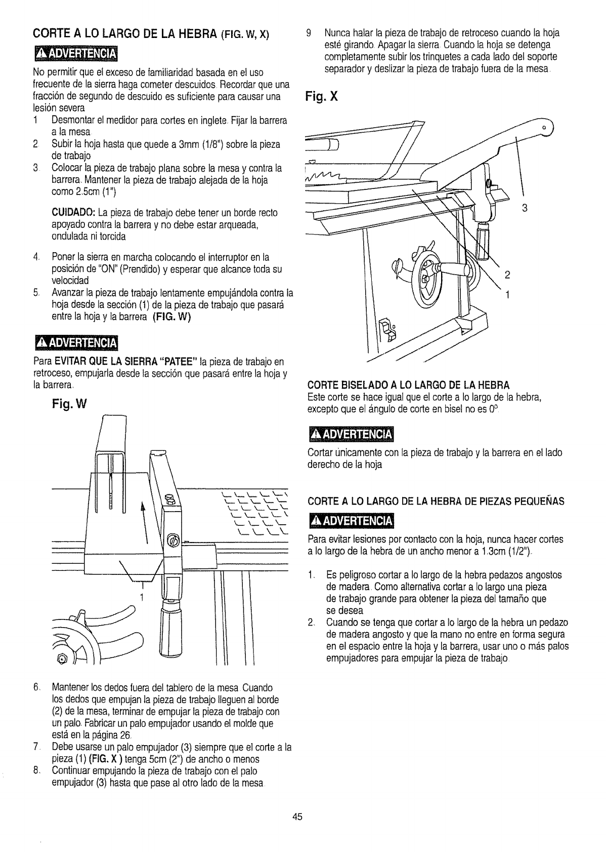
CORTE A LO LARGO DE LA HEBRA (FIG. W, X)
No permitirque et exceso de familiaridadbasada en et uso
frecuente de la sierrahaga cometer descuidos Recordarque una
fracciSn de segundo de descuidoes suficiente paracausar una
lesi6n severa
1 Desmontarel medidor paracodes en inglete Fijar la barrera
a la mesa
2 Subir ta hoja basraque quede a 3ram (118")sobre fa pieza
de trabajo
3 Cotocarla piezade trabajo plana sobre la mesa y contra la
barrer& Mantenerla pieza de trabajo alejada de la hoja
como 2.5cm (1")
CUIDADO: La pieza de trabajo debe tener un borderecto
apoyadocontra la barreray no debe estar arqueada,
ondutada nitorcida
4 Poner lasierra enmarcha colocando el interruptoren la
posici6nde "ON"(Prendido)y esperar que alcancetoda su
velocidad
5 Avanzarla pieza de trabajo lentamente empujAndolacontrala
hoja desde la secci6n (I) de la pieza de trabajo que pasar_
entre la hojay la barrera (FIG. W)
Para EVITAR QUE LA SIERRA"PATEE" la pieza de trabajoen
retroceso,empujartadesde ta secci6n que pasara entre tahoja y
la barrera,
Fig. W
®
1
\
k.._ k.._ k__ k__. ",-,
k,_, X__ \__ k-- \
k_. \w k._ k__
Nunca halar la pieza de trabajode retrocesocuando la hoja
este girando Apagarla sierra Cuando fa hoja se detenga
completamente subir los trinquetes a cada lado del soporte
separador y deslizarla pieza de trabajo fuera de la mesa
Fig. X
3
2
!
CORTE BISELADO A LO LARGO DE LA HEBRA
Este corte se hace igual que el corte a Io largode la hebra,
excepto que el _ngulo de corteen bise! noes 0°
Cortar [inicamente con la piezade trabajo y ta barreraen el lado
derecho de la hoja
CORTE ALO LARGO DE LA HEBRA DE PIEZAS PEQUENAS
Paraevitar lesiones porcontacto con la hoja, nunca hacer cortes
a Io largo de la hebra de unancho menor a 13cm (1/2")
1 Es petigrosocortar a Io largo de la hebrapedazos angostos
de madera Como alternativacortar a Io largo una pieza
de trabajo grande para obtenerla pieza del tamafio que
se desea
2. Cuando se tenga que cortara Io largo de la hebra un pedazo
de madera angosto y que ta mano no entre en forma segura
en el espacio entre ta hoja y la barrera, usar uno o m_s palos
empujadores para empujar la pieza de trabajo
6. Mantenerlos dedosluera de! tablero de Ia mesa Cuando
los dedos que empujanla pieza de trabajo Ileguenal borde
(2) de la mesa, terminarde empujar la piezade trabajocon
un pato.Fabricarun paloempujador usando et moldeque
est_ en lapAgina26
7 Debe usarseun palo empujador (3) siempre que el corte a la
pieza (1) (FIG.X ) tenga 5cm (2") de ancho o menos
8. Continuarempujando ta pieza de trabajo con el palo
empujador (3) hastaque pase al otro lado de ta mesa
45
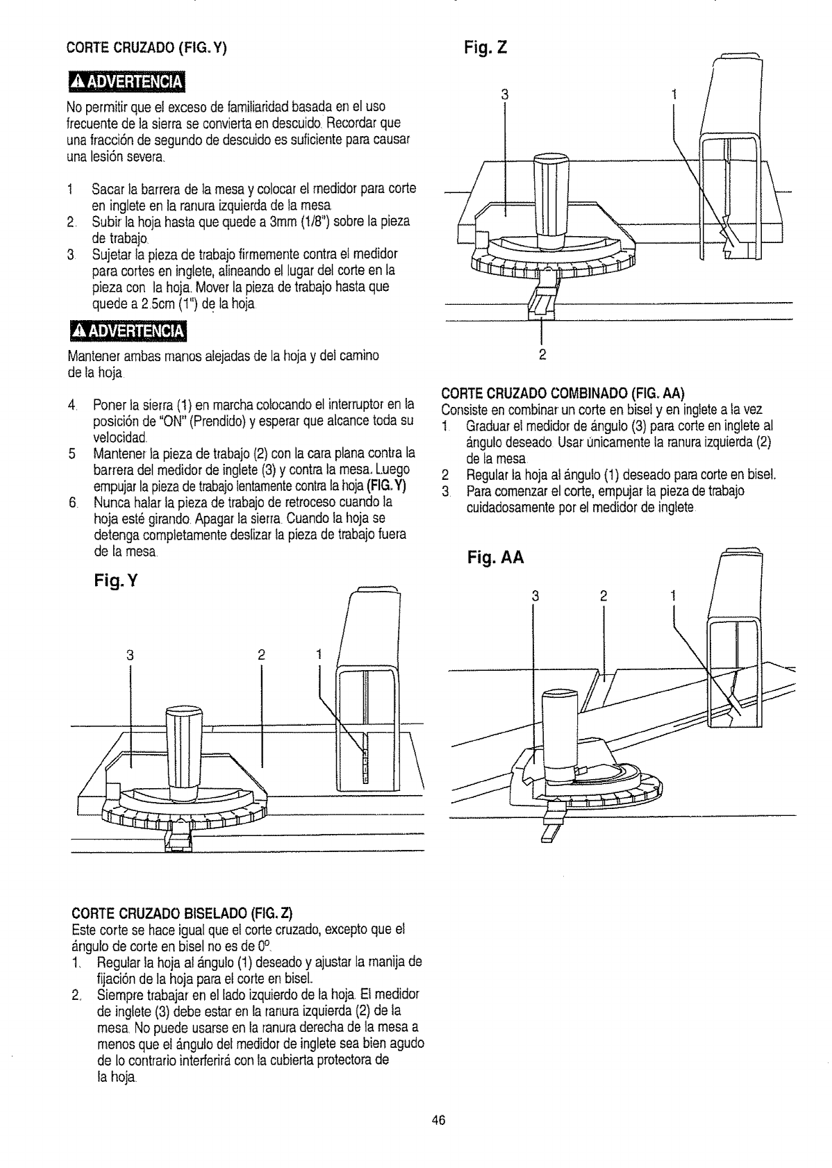
CORTE CRUZADO (FIG. Y) Fig. Z
No permitir que el exceso de familiaridadbasada en el uso
frecuente de ta sierra se conviedaen descuido. Recordarque
unafracci6n de segundo de descuidoes suficiente paracausar
una lesi6n severa.
1 Sacar la barrera de la mesa y colocar el medidor para corte
en inglete en la ranura izquierdade la mesa,
2, Subir la hoja hasta que quedea 3ram (t/8") sobre la pieza
de trabaio
3 Sujetar ta pieza de trabajofirmementecontra el medidor
para cortes en inglete, alineandoel lugar det corte en la
p]eza con la hoja. Moverla piezade trabajo hasta que
quede a 2 5cm (1") de ta hoja
Mantener ambas manos atejadasde la hoja y del camino
de la hoja
4. Poner la sierra (1) en marchaco!ocando el interruptoren ta
posid6n de "ON" (Prendido)y esperar que atcance toda su
velocidad
5 Mantener ta pieza de trabajo (2) con la cara planacontra la
barre_adel medidor de ingtete(3) y contrala mesa, Luego
empujarla piezade trabajolentamentecontrala hoja(FIG.Y)
6. Nunca halar ta pieza de trabajode retroceso cuando la
hoja est6 girando Apagar la sier[a. Cuando la hoja se
detenga completamente deslizar ia pieza de trabajo fuera
de [amesa.
Fig.Y
2 !
3
I
2
!
CORTE CRUZADO COMBINADO (FIG. AA)
Consisteen combinar un corte en bisel yen ingletea la vez
t Graduarel medidor de _.nguto(3) paracode en inglete al
angulodeseado Usar unicamente la ranura izquierda(2)
de ta mesa
2 Regularta hojaal angu!o(t) deseado paracode en bisel.
3. Paracomenzar el code, empujar la piezade trabajo
cuidadosamentepot el medidor de inglete
Fig. AA
CORTE CRUZADO BtSELADO (FIG. Z)
Este corte se hace igual que el corte cruzado, excepto que e!
_ngulo de corte en bisel no es de 0°.
1, Regular la hoja al #,ngulo(t) deseado y ajustarla manija de
fijaci6nde la hoja para et code en biseL
2, Siempre trabajar en el lado izquierdode ta hoja El medidor
de ingtete(3) debe estar en la ranuraizquierda(2) de la
mesa, No puede usarse en ta ranuraderecha de la mesa a
menos que el _.ngulodel medidor de ingletesea bien agudo
de lo contrario interferiracon la cubierta protectora de
la hoja.
46
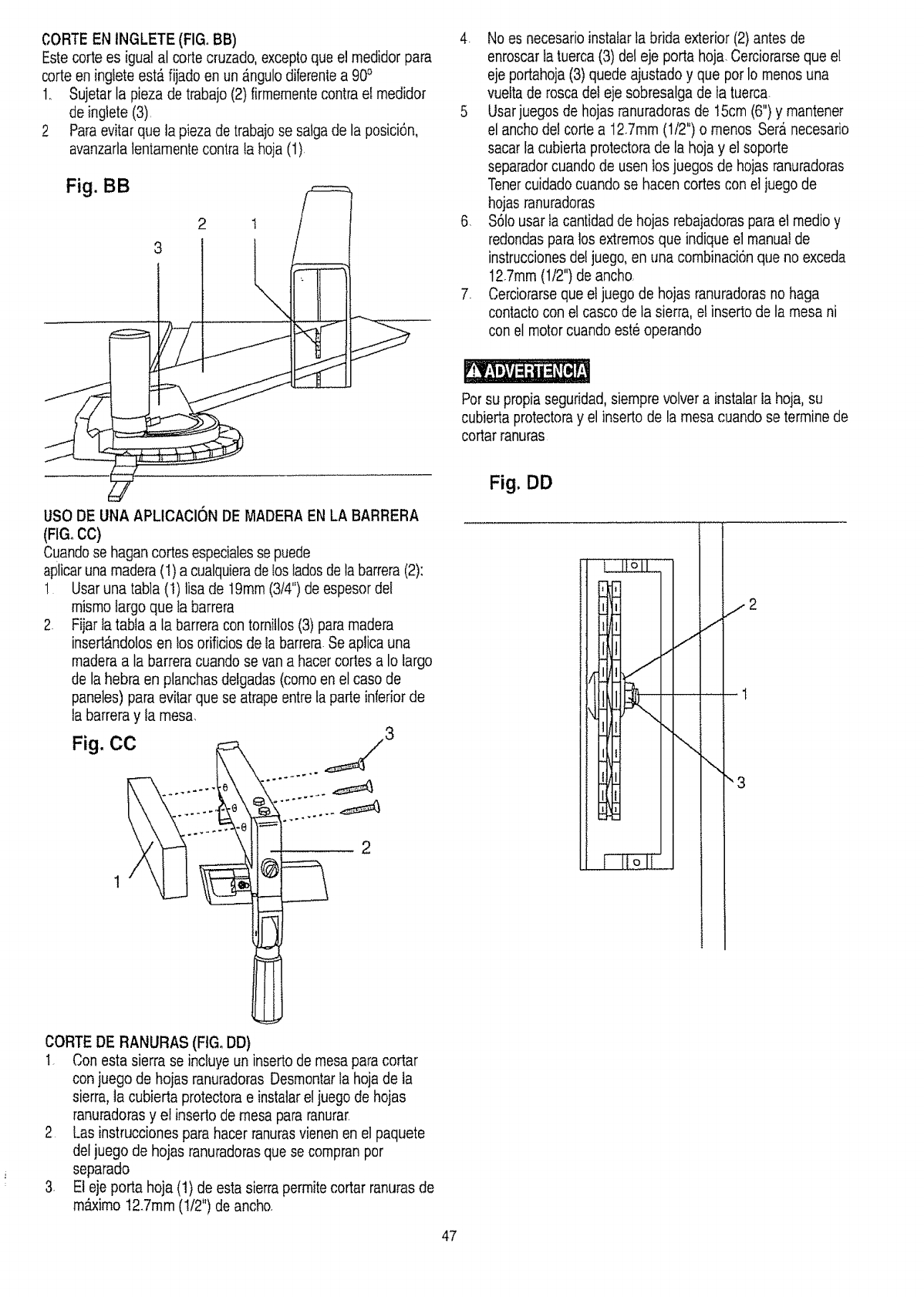
CORTE EN INGLETE (FIGoBB)
Estecorte es igua! al corte cruzado, exceptoque el medidor para
corte en inglete est_fijado en un _ngulo diferentea 900
1. Sujetar la pieza de trabajo (2) firmementecontrael medidor
de inglete (3),
2 Paraevitar que la pieza de trabajo se satgade la posici6n,
avanzarlatentamentecontrata hoja (1)
Fig. BB
2 t
USO DE UNA APLtCACION DE MADERA EN LA BARRERA
(FIG, CC)
Cuandose hagancortes especialesse puede
aplicaruna madera(t) a cualquierade los ladosde la barrera(2):
1 Usar una tabla (1) lisa de 19ram(3/4") de espesordel
mismo largo que ta barrera
2. Fiiar fa tabla a la barreracon tornitlos (3) paramadera
insefl_ndolos en los orificiosde labarrera Se aplica una
madera a la barreracuando se van a hacercortes a Io largo
de lahebra en planchasdelgadas (comoen el caso de
paneles) para evitarque se atrape entre ta parle inferior de
la barrera y la mesa.
Fig. CO
......... _3
IC
CORTE DE RANURAS (FIGoDD)
I. Con esta sierra se incluye un inserto de mesapara cortar
con juego de hojas ranuradoras Desmontarla hojade la
sierra,la cubierta protectorae instatarel juegode hojas
ranuradorasy el inserto de mesa pararanurar.
2 Las instrucciones para hacer ranurasvienen en el paquete
defjuego de hojas ranuradorasque se compran per
separado
3. El eje porta hoja (1) de esta sierra permitecortar ranuras de
m&ximo 12.7mm (!/2") de ancho.
4 No es necesarioinstalarta brida exterior (2) antes de
enroscarfatuerca (3) deleje porta hoja. Cerciorarseque e!
eje portahoja(3) quede ajustado y que pot Io menos una
vuelta de rosca del eje sobresalga de Ia tuerca.
5 Usarjuegos de hojas ranuradoras de t5cm (6") y mantener
el ancho de! cofle a 127mm (1/2") o menos Sera necesario
sacarla cubierta protectora de la hoja y el soporte
separadorcuando de usen los juegos de hojas ranuradoras
Tenercuidadocuando se hacen cortes con el juego de
hojas ranuradoras
6. S61ousar ta cantidadde hojas rebajadoraspara el medio y
redondas paralos extremosque indique el manual de
instruccionesdel juego, en una combinaci6nque no exceda
127mm (1/2") de ancho.
7. Cerdorarse que el juego de hoias ranuradorasno haga
contactocon e! casco de ta sierra, el inserto de la mesa ni
con el motor cuando este operando
Porsu propiaseguridad, siemprevolver a instalar ta hoja, su
cubiertaprotectoray el inserto de la mesa cuando se termine de
cortar ranuras
Fig, DD
/2
.t
"3
47
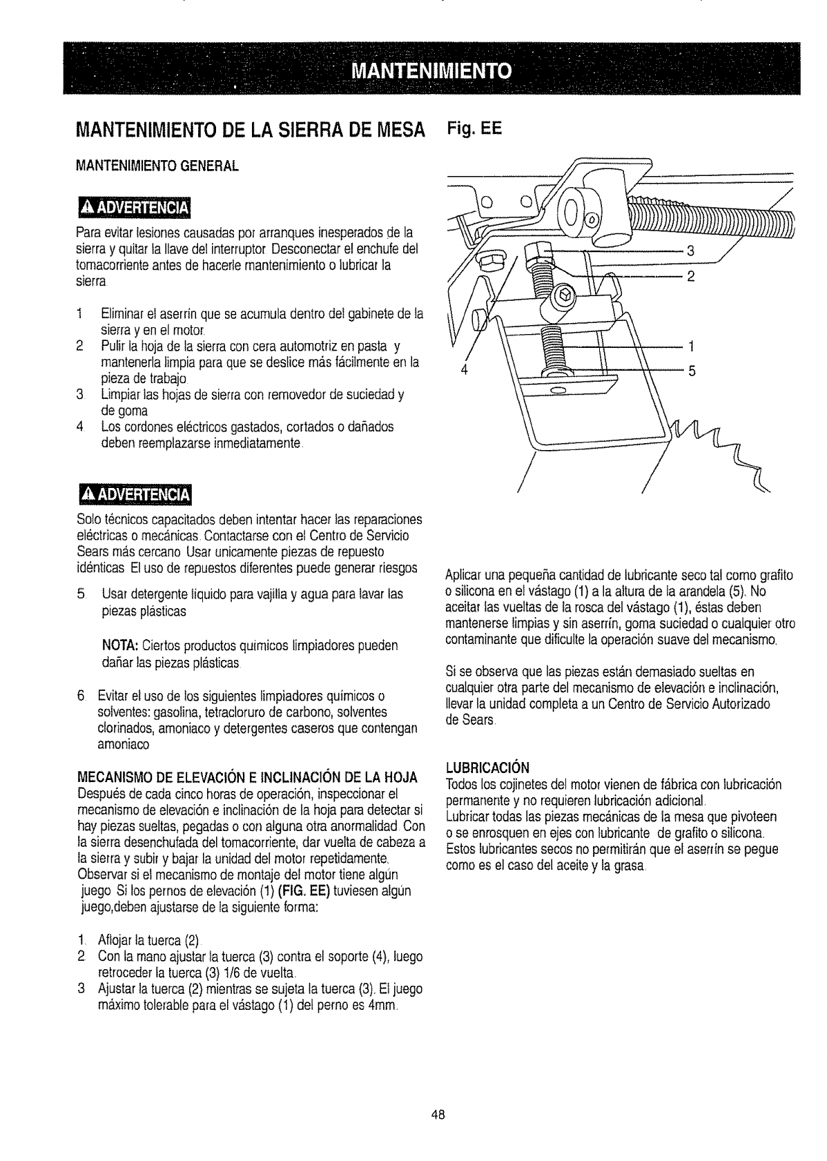
MANTENIMIENTODE LASIERRA DE MESA
MANTENIMIENTOGENERAL
Paraevitartesionescausadas pot arranques inesperadosde la
sierra y quitar la Ilavedel interruptor Desconectar e! enchufedel
tomacorrienteantes de hacerie mantenimiento o lubricar la
sierra
t EliminareI aserrin que se acumula dentro dei gabinete de ta
sierra yen el motor.
2 Pufir ia hojade ta sierra con cera automotriz en pasta y
mantenerlalimpia pata que se destice m_.sfacilmenteen la
pieza de trabajo
3 Limpiartas hoias de sierra con removedor de suciedad y
de goma
4 Los cordoneselectricosgastados,cortados o daSados
deben reemplazarseinmediatamente
Solo t_cnicos capacitadosdeben intentarhacer tas reparaciones
electricas o mecanicas Contactarse con el Centrode Servicio
Sears rnAscercano Usarunicamente piezas de repuesto
identicas Eluso de repuestosdiferentes puede generarfiesgos
5 Usar detergenteliquido para vajiltay agua papalavar fas
piezasptasticas
NOTA: Ciertos productosquimicos limpiadores pueden
da5ar]aspiezaspl#,sticas
Evitarel uso de los siguientes limpiadores quimicos o
solventes:gasolina,tetraclorurode carbono, sotventes
dorinados, amoniaco y detergentescaseros que contengan
amoniaco
MECANISMO DE ELEVAClONE INCLINACION DE LA HOJA
Despu_s de cada cinco horas de operaci6n,inspeccionar el
mecanismode elevaci6ne inclinaci6nde la hoja paradetectar si
hay piezas sueltas,pegadas o con atguna otra anormalidad Con
la sierra desenchufadadel tomacorriente,dar vueita de cabeza a
la sierra y subir y bajar la unidad det motor repetidamente.
Observar si ef mecanismode montajedel motor tiene algLin
juego Si los pernos de etevaci6n(t) (FIG. EE) tuviesen atgun
juego,debenajustarse de la siguienteforma:
1. Aftojar tatuerca (2)
2 Con la mano ajustarla tuerca (3) contla el soporte (4), luego
retrocederta tuerca (3) t/6 de vuelta,
3 Ajustar la tuerca (2) mientras se sujeta la tuerca (3). El juego
mb.ximotoletablepara el v_stago (1) de! pemo es 4ram
Fig. EE
45
/
Aplicaruna pequehacantidadde tubricante secotal como grafito
o siliconaen el vastago (1)a la altura de la arandela (5). No
aceitarlas vueltas de la roscadel v_stago (1), _stas deben
mantenerselimpias y sin aserrin, goma suciedad o cualquier otro
contarninanteque dificulte la operaci6nsuave del mecanismo.
Si se observa que las piezas estAndemasiado sueltas en
cualquier otra parte del mecanisrnode elevaci6ne inclinaci6n,
llevar la unidad completaa un Centrode ServicioAutorizado
de Sears.
LUBRICACION
Todoslos cojinetes del moto_vienen de f_bfica con lubricacion
permaner_tey no requierentubricaci6nadicional.
Lubricartodas las piezasmec_nicasde ta mesaque pivoteen
o se enrosquenen ejes con lubrieante de grafitoo siticona.
Estos tubricantessecos no pefmitiran que el aserdn se pegue
como es el caso del aceitey la grasa.
48
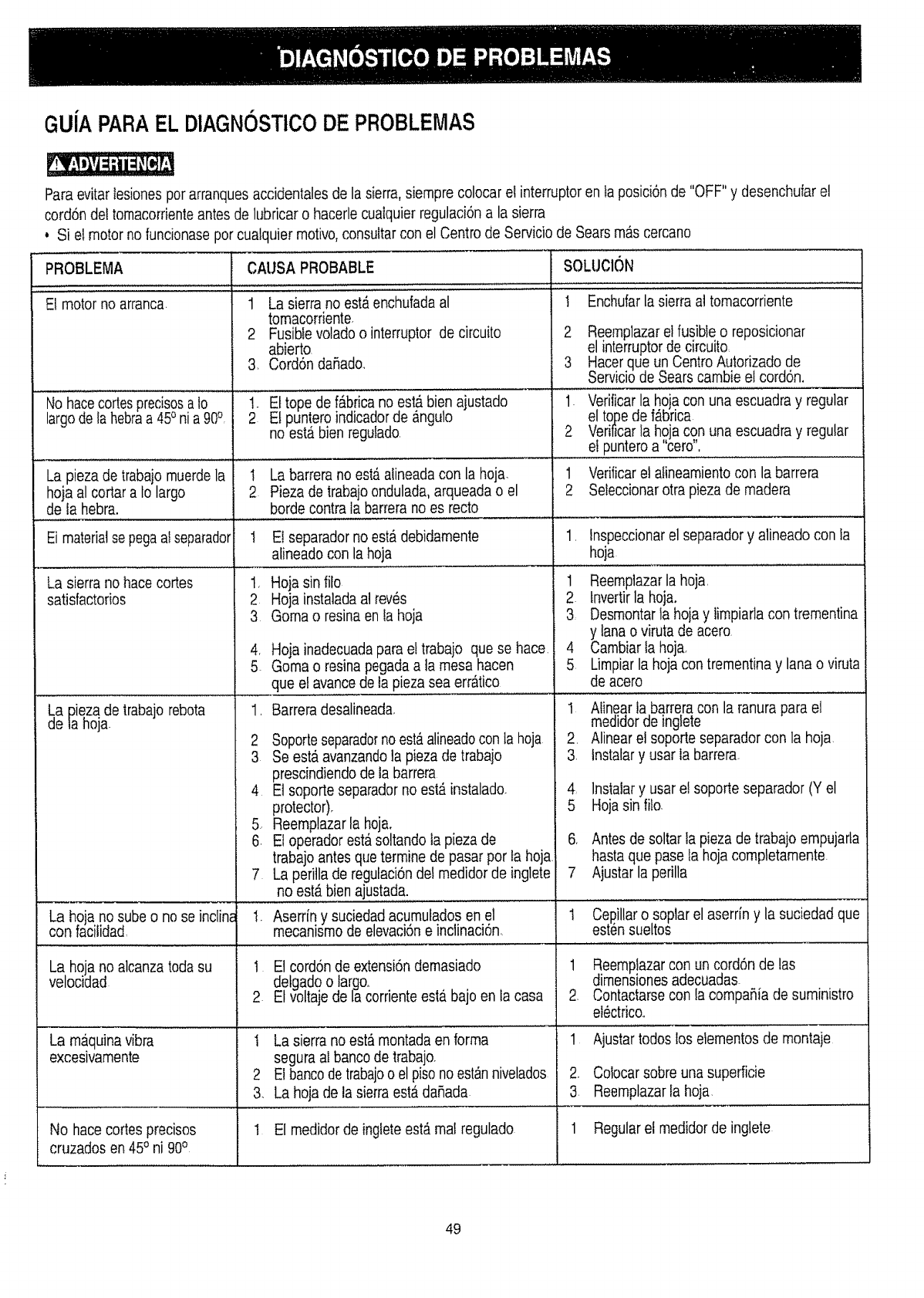
GUJAPARAEL DIAGNOSTtCODE PROBLEMAS
Paraevitar tesiones porarranquesaccidentales de la sierra,siempre colocar et interruptoren ta posici6nde "OFF" y desenchuiar el
cord6n det tornacorrienteantesde iubricar o hacerle cuaiquier regulaci6na la sierra
o Si el motor no funcionasepot cualquier rnotivo,consultar con el Centro de Servicio de Sears mas cercano
PROBLEMA
El motor no arranca.
I.................
No hacecortesprecisosa 10
largodela hebraa 45oni a 90°
La pieza de trabajo muerdela I
hoja al cortar a 18largo 2
de la hebra.
ICA!!SA PROBABLE ......................
1 La sierra no est,,enchufadaal
tornacorriente
2 Fusiblevolado o interruptor de circuito
abierto
3. Cord6n daRado..
1.
2Et tope de f_brica no estb,bien ajustado
Et puntero indicadorde _nguIo
no esta bien regufado
La barrera no est_ atineadacon la hoja
Pieza de trabajo ondulada, arqueada o el
borde contra ta barrerano es recto
........ , , , _ , ,,_ ,, ,,,,,,,,,,,,............... _..........................
Ei materialse pegaai separador t El separadorno est_ debidamente
alineado con la hoja
La sierra no hace cortes
satisfactorios
La Diezade lrabajo rebota
de la hoja
La hoja no sube o no se inclin_
con facilidad
1, Hoja sin filo
2 Hoja instaladaal rev_s
3 Goma o resina en la hoja
4, Hoja inadecuada parael trabajo que se hace.
5 Gorna o resina pegadaa la mesa hacen
que el avancede la pieza sea err_tico
1. Barrera desalineada,
2 Soporteseparadornoestb.alineadocon la hoja
3 Se esta avanzandola pieza de trabajo
prescindiendode la barrera
4 El soporte separadorno est_ instalado.
protector).
5. Reemplazarla hoja,
6. El operadorest&soltandola pieza de
trabajo antesque termine de pasar por ta hoja.
7 La peritla de regulaci6n del rnedidorde inglete
no est,. bienajustada.
1. Aserriq y suciedad acurnuladosen el
rnecanlsrnode elevaci6ne inclinaciSn
No hace cortes precisos
cruzados en 45oni 90o
La hoja no alcanzatoda su I E1cord6n de extensi6ndemasiado
velocidad detgado o largo°
2 Et voltaje de la corrienteesta.bajo en la casa
La rnaquinavibra t La sierrano est_ montadaen forma
excesivamente segura aI banco de trabajo.
2 El bancode trabajoo el pisono est_nnivelados
3. La hoja de la sierra est_ daSada
I El medidor de inglete est_ mal regulado
SOLUCl()N
I Enchufarla sierra al tornacorriente
2 Reernplazarel fusible o reposicionar
el interruptorde circuito
3 Hacerque un Centro Autorizado de
Serviciode Sears carnbie et cordon,
1. Verilicarla hojacon una escuadra y regular
el tope de f_brica
2 Verificarla hojacon una escuadra y regular
...........el puntero a "cero",
1 Verificarel afinearnientocon la barrera
2 Seleccionarotra pieza de rnadera
1. lnspeccionarel separador y alineado con ia
hoja
1 Reemplazarla hoja,
2. tnvertirla hoja.
3 Desmontarta hoja y limpiarla con trernentina
y lana o viruta de acero
4 Cambiarta hoja.
5 Limpiarla hoja con trementina y lana o viruta
de acero
t Alinear ta barreracon la ranurapara el
medidorde ingfete
2. Alinearel soporte separador con la hoja
3. lnstalary usar la barrera
4 lnstaiary usar e! soporte separador (Y el
5 Hoja sin filo.
6. Antesde soltar la pieza de trabajo empujarla
hasta que pase ta hoja completamente
7 Ajustar la perilla
1 Cepillarosoplar el aserrin y la suciedad que
esti_nsueltos
1 Reernplazarcon un cord6n de las
dirnensionesadecuadas
2. Contactarsecon ia cornpa_ia de suministro
el_ctrico..
1 Ajustartodos los elementos de rnontaje
2, Colocarsobre una superficie
3 Reemplazarfa hoja
1 Regularel medidor de inglete
49
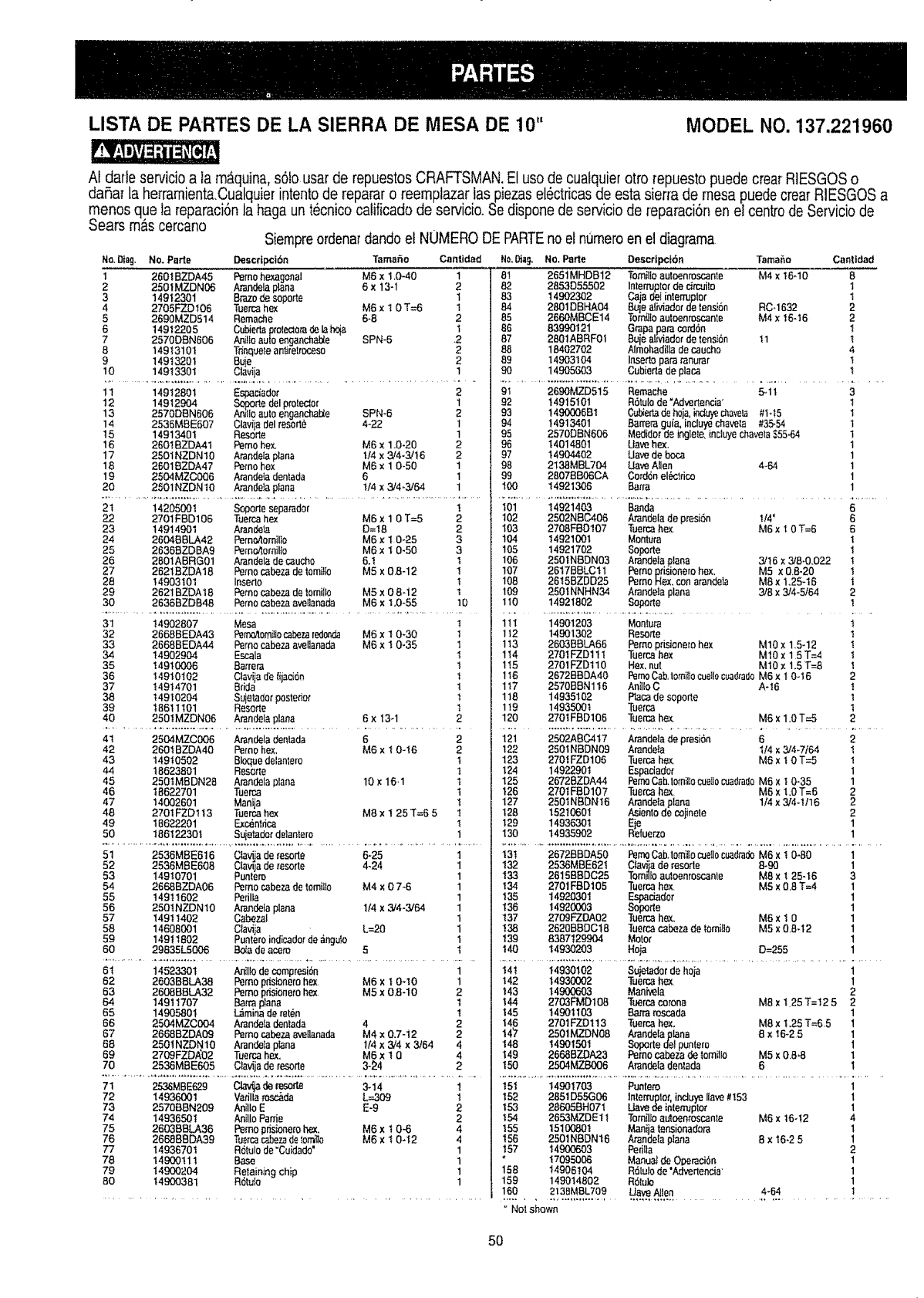
LISTA DE PARTES DE LA SIERRA DE MESA DE 10" MODEL NO. 137.221960
At darle sewicio a la m_quina,s61ousar de repuestos CRAFTSMAN.El use de cuatquierotto repuesto puede crear RIESGOSo
daRar la herramientaCualquier intento de reparar o reemptazar las piezasel6ctricasde esta siena de mesa puedecrear RIESGOS a
manes que ia reparaci6n la haga un tecnico calificado de servicio.Se disponede servicio de reparaciTnen el centrede Servicio de
Sears mas cercano Siempreordenardandoet NUMERODE PARTEno el numeroen el diagrama
DescfiF_16n Tamafio Cantidad Ho.Dtag. No. Parte Oescripcf6nNo.Diag. No. Pade
126Ot BZDA45 Pemo hexagonal M6 xt.0-40 1
225OIMZDN06 Amndela p_na 6x13-1 2
314912301 Braze de soporte 1
4 2705FZDt06 Tuercahex M6 x I 0 T=6 1
5 2690MZD514 Remache 6-8 2
6 14912205 Cubie_ protectorade lahqa 1
7 2570DEN606 Ar_lloauto enganchaJ_e SPN-6 .2
8 14913101 Tdnqueteae_relrocese 2
9 14913201 Buie 2
10 149t 3301 Clavija 1
TamaSa Canlidad
8! 2651MHDB12 Tomilloauloenroscante M4 xt6q0 8
82 2853D55502 Interruptotde c_fcuito I
83 14902302 Caja delinler_pler I
84 2801DBHA04 BUle aliviador de tension RO.1632 2
85 2660MBCE14 Torn{Jtoauloenroscante M4 x 16-I 6 2
86 83990121 Grapapara mrd6n t
87 2801ABRF01 Buiealtviador de tensi6n t I 1
88 18402702 Aimohadiila decaucho 4
89 14903104 Insertopara ranurar t
90 14905603 Cubieda de placa 1
1t 14912801 Espadador 2
12 14912904 So_, rte del ptotecior 1
13 2570DAN606 An_lloauto enganchz_e SPN-6 2
14 2536MBE607 Clavija del resotte 4-22 1
15 1491340t Reso_e 1
16 2601BZDA41 Pemo hex. M6 x 1.0-20 2
17 2501NZDN10 ArandeIaplana t/4 x3/4-3,/t6 2
18 26018ZDA47 Pemo hex M6 x 1 0-50 1
19 2504MZC6O6 Atande_adentada 6 1
20 2501NZDNtO Arandela plana t/4 x3/4-3264 1
9I 2690MZD515
92 14915101
93 1490006 B1
94 14913401
95 2570DAN606
96 14014801
97 14904402
98 2138MBL704
99 2807BB06CA
!00 14921306
2t 14205001 Soporte separader ! I01 14921403 Ban_
Remache 5_1t 3
RTtulo de "Advertencia' 1
Cub_edadehoja.induyechave_ #1-t5 1
Barrera guia, incluyechavet_ #35.54 1
Medider de inglete,incluye chaveta$55.64 1
Uave hex, 1
Uave de boca 1
Uave Alien 4.64 1
Cord6n el_ctdco 1
Batra 1
6
22 2701FBD106 Tueica hex M6 x1 0 T=5 2
23 14914901 Arandela D=t8 2
24 2604BBLA42 Pemo_omilto M6 x1 0-25 3
25 26388ZDBA9 Pem_omilto M6 x 1 0-50 3
26 2801ABRG01 Arandelade caucho 6.t I
27 2621BZDA18 Pemocabeza de tomitk_ M5 x 08-12 1
28 14903101 Insedo t
29 26218ZDAt8 Perno _beza de lomiIto M5 x 0 8-12 1
30 2636BZD848 Perno cabeza ave[lanada M6 xt.0-55 10
31 14902807 Mesa
32 2668BEDA43 Femc_lomilIoca_za redo,q_ M6 x1 0-30
33 26688EOA44 Pemo c_beza avellanada M6 x t 0-35
34 14902904 Escala
35 14910006 Barrera
36 14910102 Ctavijad'e {ijaci6n
37 14914701 Brida
38 14910204 Sujetador posterior
39 1861tt01 Resorte
40 2501MZDN06 Arandela plana 6 x 13-1
t
I
1
1
1
1
I
1
t
2
4t 2504M.ZC006 Atandeladeniada 6
42 2601BZDA40 Pemo hex, M6 x 10-t6
43 14910502 Bioque delantero
44 t8623801 Resorte
45 2501MBDN28 Arandela pIana 10 x 16.1
46 t 8622701 Tuerca
47 14002601 Manija
48 27OIFZDtt3 Tuercahex M8x 1 25 T=6 5
49 I8622201 Exc_nlfica
50 186122301 Suietader detantero
2
2
t1
tt
I
1
1
1
102
103
104
105
106
107
108
I09
1t0
11t
112
113
114
115
1t6
117
118
1!9
120
2502NBC406 Arande!a de presi6n t/4' 6
2708FBDt07 Tuetcahex M6 x 1 0 T=6 8
14921001 Montura t
14921702 Soporte t
2501NBDN03 Arandela plaea 3/16 x 3,/8.0.022 t
2617BBLCtl Pemo prisionero hex, M5 x 0.8-20 I
2615BZDD25 Pemo Hex.con arandeta M8 x1.25-t 6 i
2501NNHN34 Arandeta plaoa 3/8 x 3/4-5/64 2
14921802 Sopo_le I
14901203 Montura t
14901302 Resoffe 1
2603BBLA66 Pemo prisionero hex M10 x 1.5-12 t
2701FZD111 Tuercahex M10x 15T=4 1
2701FZD110 Hex.nut M10x 1.5 T=8 I
26728BDA40 PernoCab,lomiIfocueilocuad_adoM6x 1 O-16 2
2570BBN116 Aniilo C A-16 t
14935102 P1acade sopofle 1
14935001 Tuerca t
2701FBD106 Tuen_ he,x. M6 x 1.0 T=5 2
121 2502ABCAt7 Arandela de presi6n 6 2
122 2501NBDN09 Arandeia I/4 x 324.7/64 1
123 2701FZD106 Tuerca hex M6 x 1 0 T=5 I
124 14922901 Espaciadef I
125 2672BZDA44 PernoCab.lomillooJeI_ocuadfadoM6 x 1 0-35 1
126 2701FAD107 Tuerca hex. M6 x 1.0 T=6 2
127 2501NBDN!6 Arandefa plana 1/4 x 3/4-t/16 2
128, 15210601 Asiento de coiinele 2
129 14936301 Eie 1
130 14935902 Refuerzo 1
5t
52
53
54
55
56
57
58
59
6O
6t
62
63
64
65
66
67
68
69
70
2536MBE616 CIavijade _eserte 6-25 1
2536MBE608 Clawja de tesorte 4-24 1
14910701 PunIero 1
2668BZDA06 Perno cabeza de tomilta M4 x 0 7-6 1
14911602 Perilla 1
2501NZDN10 Ar_ndelaplana 1/4 x 3/4-3/64 1
149! t402 Cabezal 1
14608001 Ctavija L=20 1
14911802 Pun_eroindicadorde angu_ 1
29835L5006 Bo_ade acem 5 t
14523301 Anillo de compresi6n
2603BBLA38 Pemo p_isionetohe:(. M6 xt 0-t0
2608B8LA32 Pemo p,,isi_netohex. M5 xO8-10
149t t707 Barra pIana
14905801 !._,iminade ret_}n
2504MZC004 Atandeta deolada 4
2668BZDAO9 Pemo cabeza a.a_tlanada M4 x 0.7-t2
2501NZDN!0 Arandeta p_na 114x 324 x3/64
27OgFZD/_02 Tuerca he.x. M6 x t 0
2536MBE605 C4av_jade tesode 3-_4
1
1
2
t
t
2
2
4
4
2
71 2-_MBE629 Clav_ de _esofte 3-14 1
72 14936001 Vatilla to_da L=309 1
73 2570BBN209 Anitlo EE-9 2
74 14936501 Anillo Panie 2
75 260388LA36 Pemo pdsione_ohex, M6 x t0-6 4
76 26888BDA39 Tue_car._bezade_er'ni_ M6 x! 0-t2 4
77 1493670 t Rotulo de "Cuidado" 1
78 149O0111 Base 1
79 14900204 Retaining chip 1
80 14900381 R61ulo 1
t31 2672BBDA50 PemoCabJomii_ocue_oc_dmdo M6 x I 0..80 1
132 2536MBE621 Clara de resorle 8.90 1
133 26158BDC25 Tom_lIoautoenroscanle M8 x t 25-t6 3
134 2701FBDt05 Tuotca hex. M5 x 0.8 T=4 1
t35 14920301 Espadador 1
t36 14920003 Sopotte 1
137 2709F'ZDA02 Tuema hex. M6 x I 0 1
138 262088DC18 Tuetc_cabeza de lomiIIo MS x 0.8-12 1
139 8387129904 Motor 1
t40 14930203 Hoja D=255 1
t4t 14930102 Su}etador de hoia 1
142 14930002 Tuerca hex 1
t43 14900603 Mani'_ela 2
t44 2703FMDt08 Tuerca corona M8 x 1 25 T=12 5 2
145 14901103 8a.rratoscada 1
146 2701FZ0113 Tuercahe.x, M8 xt.25 T=65 1
!47 2501MZDN08 AtandeIaplana 8 xt6-25 1
148 14901501 _Soportede! puntero 1
t49 2668BZDA23 Pemo cabeza de _omil_o M5 x 0.8-8 1
150 2504MZB006 Arandeladenlada 6 I
151 14901703 Puntero 1
t52 2851D55GO6 lnterruptor, indu,ye llave#t53 1
t53 286058H07t Uave de intenuplor 1
t54 2653MZDE! t Tornilb auloem'osc_nle M6 x t6-t2 4
t55 15100801 Manija te_ionadeta 1
156 2501NBDN!6 Arandela ptana 8 x 16-2 5 1
t57 14900603 Periita 2
* t 7095006 Manual de Ol_reci6o 1
158 14905104 Rdlulo de "Adverlencia 1
159 149014802 R6{a}o 1
160 2138MBL709 Uave Atlen 4-64 I
Not shown
50
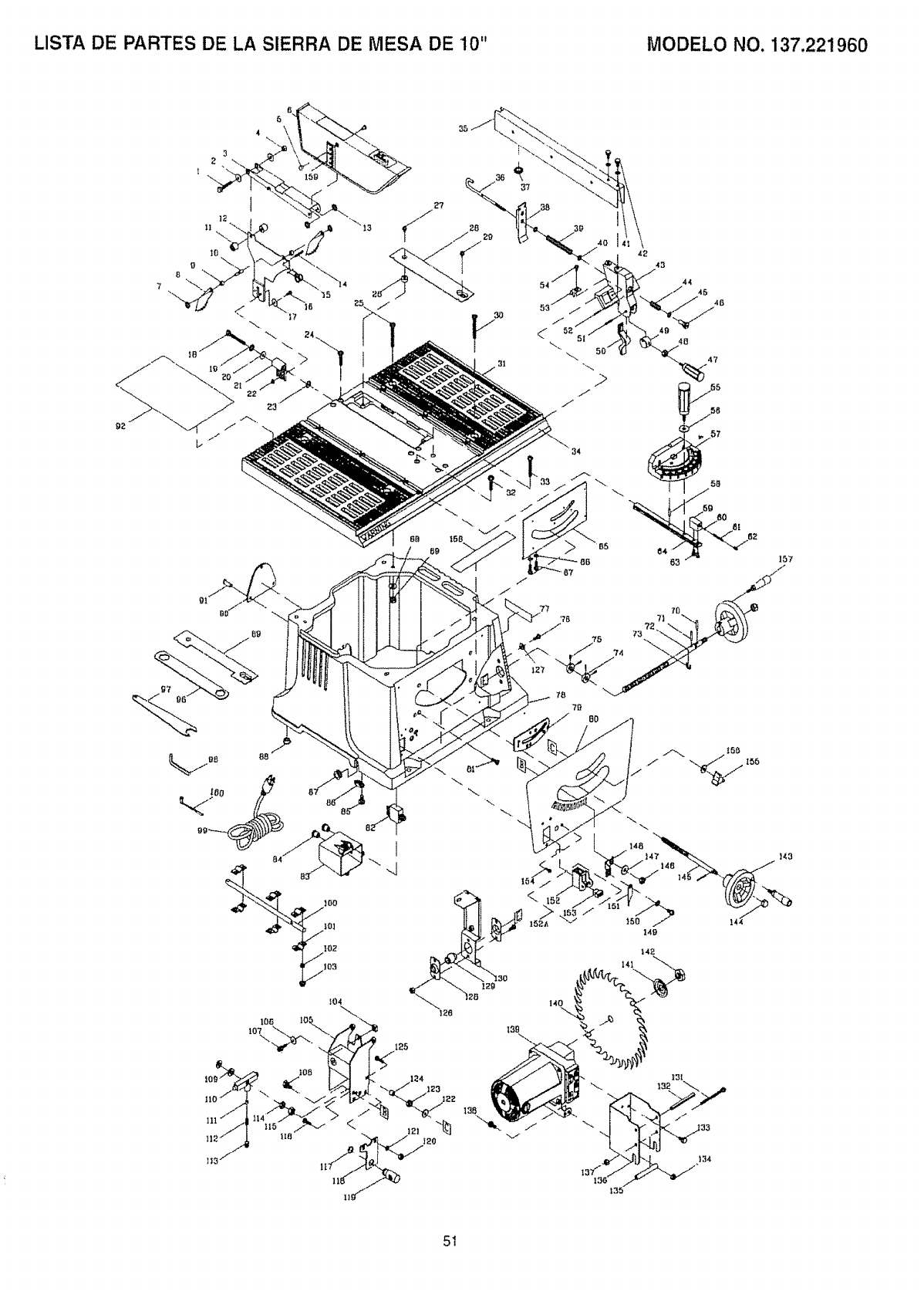
LISTA DE PARTES DE LA SIERRA DE MESA DE 10" MODELO NO. 137.221960
3
2
IO
8
7
/
5g
_0]
lOz
105
|04
lOa
1o7-\
111
82
/
7B
78
7D
BO
15 _50 149t-1 144
141
t39
5I
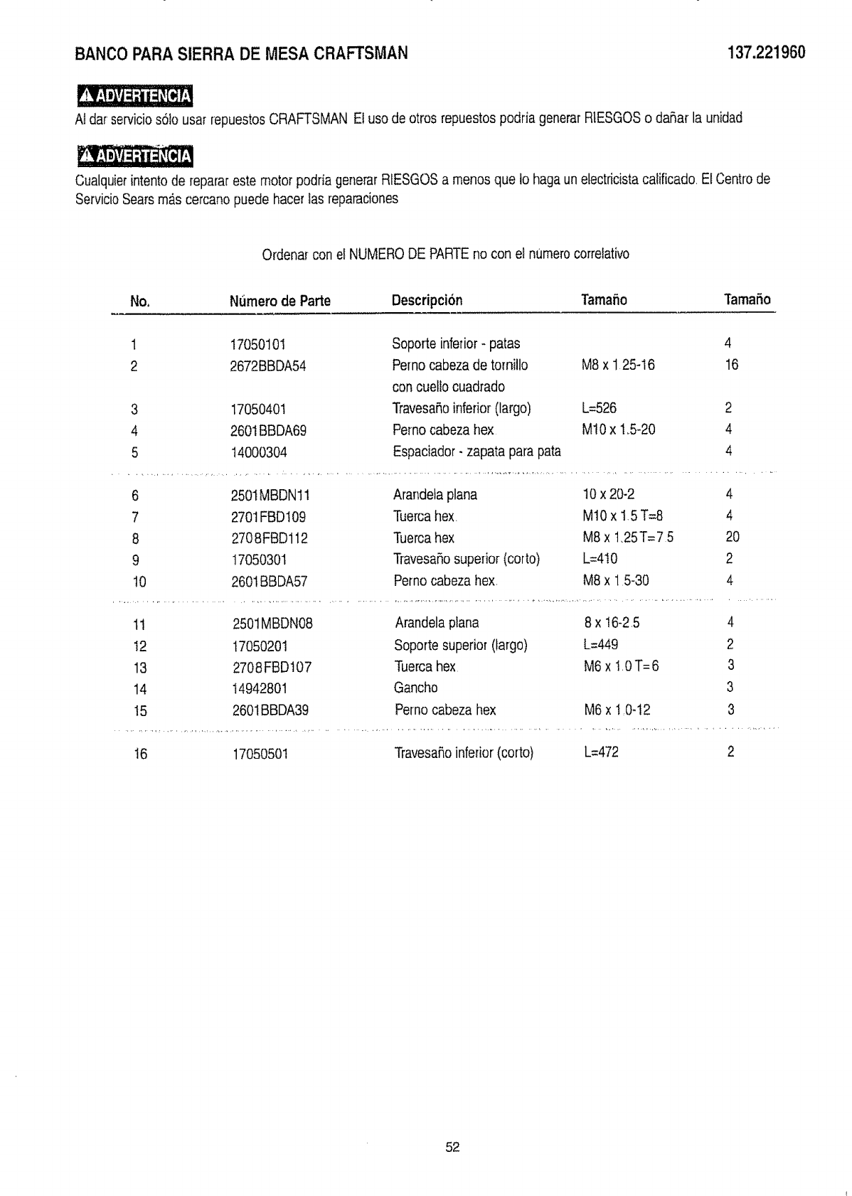
BANCOPARASIERRADE MESA CRAFTSMAN 137.221960
Ndar serviciosSlo usar repuestosCRAFTSMAN El uso de otros repuestos podria generar RIESGOSo daSar la unidad
Cualquier intentode reparar este motor podria generar RtESGOSa menos que 1ohaga un etectricistacatificado, El Centrode
ServicioSears m_s cercano puede hacer las reparaciones
Ordena_con el NUMERODE PARTEno con el numero correlativo
No, N(imero de Parte Descripcibn Tama5o TamaSo
1
2
3
4
5
17050101 Soporte inferior - paras 4
2672BBDA54 Pemo cabeza de tornillo M8 x 1 25-t6 16
con cuetlocuadrado
TravesaSoinferior (largo)
Pernocabeza hex
Espaciador- zapata para pata
17050401 L=526
2601BBDA69 M10 x t_5_20
14000304
2
4
4
6 2501MBDN11 Arandeta plana 10 x 20-2 4
7 2701FBDI09 Tuercahex M10 x 15 T=8 4
8 2708FBD112 Tuercahex M8 x t,25T=7 5 20
9 t7050301 TravesaSosuperior (corto) L=4t0 2
10 260t BBDA57 Pernocabeza hex M8 x 15-30 4
11 2501MBDN08 Arandela plana 8 x t6-25
t2 17050201 Soporte superior (largo) L=449
13 2708 FBD107 Tuercahex M6 x I. 0T= 6
14 14942801 Gancho
!5 2601BBDA39 Perno cabeza hex M6 x t :0-t2
4
2
3
3
3
t6 17050501 Travesa5oinferior (corto) L=472 2
52
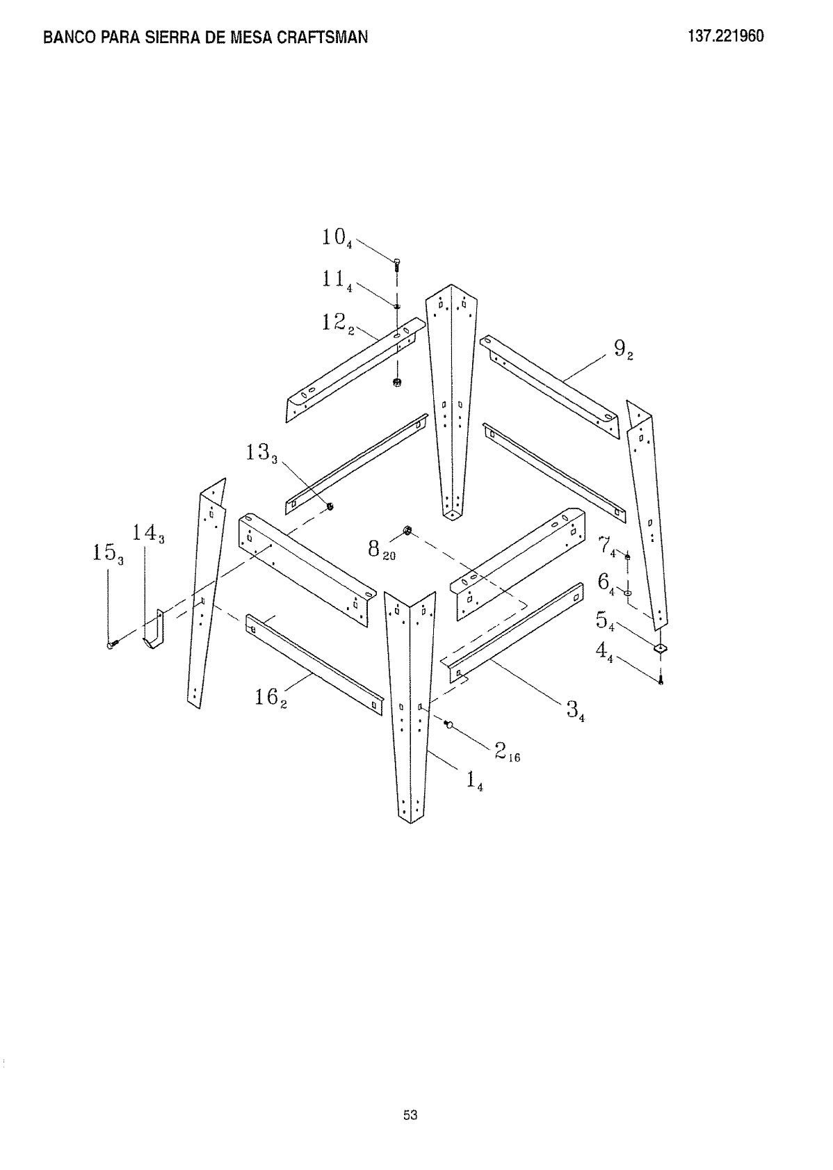
BANCO PARA SIERRA DE MESA CRAFTSMAN 137.221960
104
12
92
14
4
_I6
53
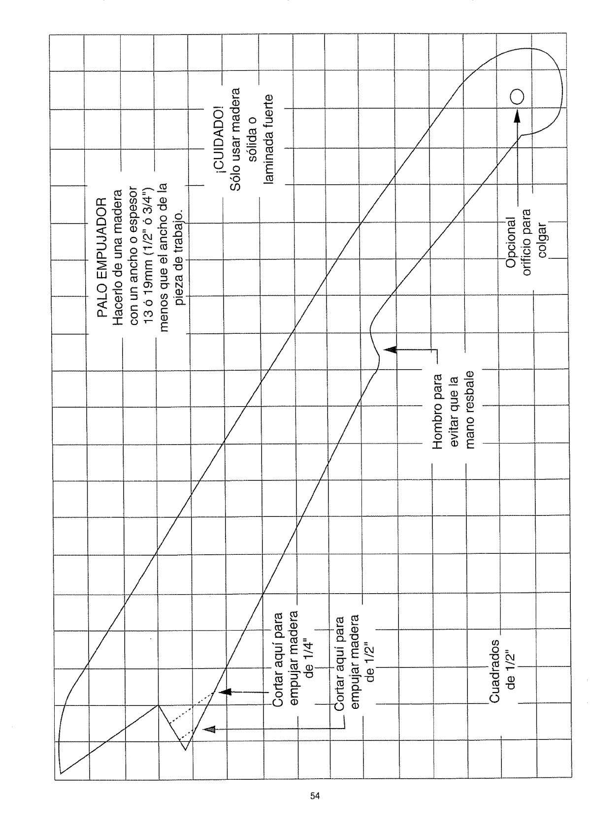
I
c_
O
.O_o
_O
cO
/
/
/i .......
/JYI::
_/./// v
(D
O
E
....................
/
7
/
y
y
I
_E k
oE
f_
/
/,.._
/ /
z / .
/Q.,.-- __
/0
/
/
/
_o
_c_E
oE
......J
O--
"O
C_
O
o,I
L
(D
54

55

iiill
For in-home major brand repair service:
Call 24 hours a day, 7 days a week
1-800-4=MY-HOME°_(_-800-469-4663)
Para pedir servicio de reparaci6n adomicilio- 1-800-676-5811
In Canada for all your service and parts needscall - 1-800-665-4455
Au Canada pour tout ie service ou les pibces
For the repair or replacement partsyou need:
Call 7 am -7 pro,7 days a week
1-800-366-PART (t-800-366-7278)
Para ordenar piezas con entrega a domicilio- 1-800-659-7084
For the location of a Sears Parts and Repair Center in your area:
Call 24 hours aday, 7days a week
1-800-488-1222
For informationon purchasing a Sears MaintenanceAgreement
or to inquire about an existing Agreement:
Call 9 am - 5 pm, Monday- Saturday
1=800-827-6655
pr
SE / S
HomeCentrar°
r
TheServiceSideofSears`°
7/98
