Craftsman 137229170 User Manual 17 DRILL PRESS Manuals And Guides L0308059
CRAFTSMAN Drill Press Manual L0308059 CRAFTSMAN Drill Press Owner's Manual, CRAFTSMAN Drill Press installation guides
User Manual: Craftsman 137229170 137229170 CRAFTSMAN 17 DRILL PRESS - Manuals and Guides View the owners manual for your CRAFTSMAN 17 DRILL PRESS #137229170. Home:Tool Parts:Craftsman Parts:Craftsman 17 DRILL PRESS Manual
Open the PDF directly: View PDF ![]() .
.
Page Count: 25
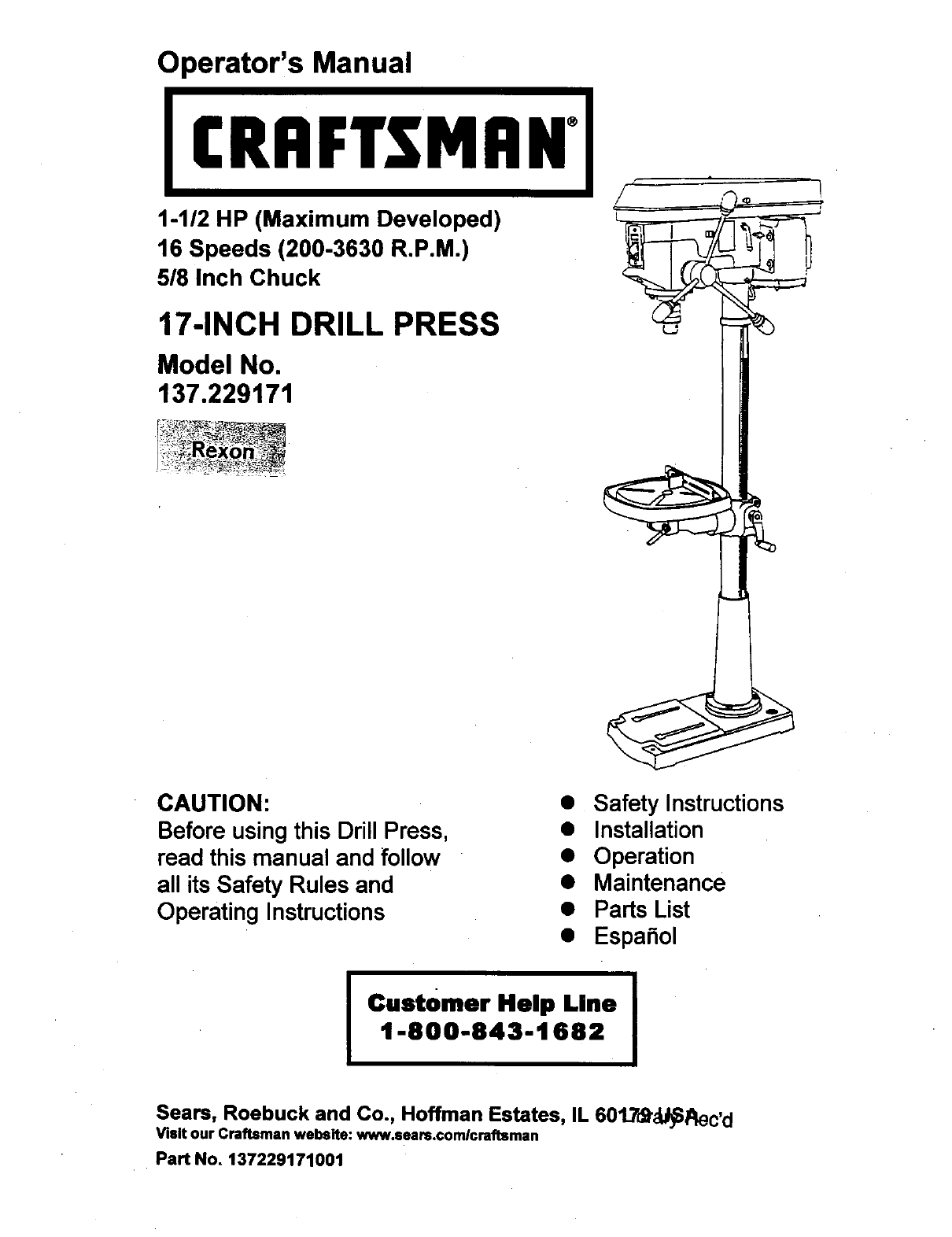
Operator's Manual
CRAFTSMAN"
1-1/2 HP (Maximum Developed)
16 Speeds (200-3630 R.P.M.)
5/8 Inch Chuck
17-INCH DRILL PRESS
Model No.
137.229171
CAUTION:
Before using this Drill Press,
read this manual and follow
all its Safety Rules and
Operating Instructions
• Safety Instructions
•Installation
•Operation
•Maintenance
•Parts List
•Espa5ol
ICustomer Help Line I
1400443-1682
Seam, Roebuck and Co., Hoffman Estates, IL 601_Td_Slalec,d
Visit our Craftsman webslte: www.sears.com/craftsman
Pa_ No. 137229171001
SECTION PAGE
Warranty ............................................................................................................... 2
Product Specifications ............................................................................................. 2
Safety Instructions .................................................................................................. 3
Accessories and Attachments .................................................................................. 6
Carton Contents ...................................................................................................... 6
Know Your Drill Press .............................................................................................. 8
Glossary of Terms .......... ......................................................................................... 9
Assembly and Adjustment ........................................................................................ 10
Operation .......................... :.................................................................................... 15
Maintenance ........................................................................................................... 20
Troubleshooting Guide ............................................................................................ 21
Parts ...................................................................................................................... 22
Espa[_ol .................................................................................................................. 25
FULL ONE YEAR WARRANTY
If this Driss Press fails due to a defect in material or workmanship within one year of date of purchase,
Sears will at its option repair or replace it free of charge•
Return this Drill Press to a Sears Service Center for repair, or to place of purchase for replacement.
This warranty gives you specific legal rights, and you may also have other rights which may vary from
state to state.
Sears, Roebuck and Co., Dept. 817 WA, Hoffrnan Estates, IL 60179
Some dust created by power sanding, sawing, grinding, drilling and other construction activities contains
chemicals known to the state of California to cause cancer, birth defects or other reproductive harm. Some
examples of these chemicals are:
Lead from lead-based paints
; Crystalline silica from bricks, cement and other masonry products
•• Arsenic and chromium from chemicallytreated lumber
Your risk from these exposures varies, depending on how often you do this type of work. To reduce your
exposure to these chemicals, work in a well-ventilated area and work with approved safety equipmentsuch as
dust masks that are specially designed to filter out microscopic particles.
Chuck Si:_e ............................ 5/8"
Speed ................................... 16 (200 - 3,600 RPM)
Motor .................................... 120V, 60 Hz, 12 Amps
Horsepower ........................... 1-1/2 HP (Max.
Developed)
Built-in Light ......................... 60 Watt (Maximum)
(Bulb not included)
Table Size ............................ 14-1/4" x 14-1/4"
Table Tilt ............................... 45 ° Right or Left
Spindle Travel ........................ 3-1/4"
Throat ................................. 8-1/2"
Base Size ............................. 11" x 20-3/8"
Height .................................. 64-7/8"
_Tirl.J ;] _[[_e]
To avoid electdcal hazards, fire hazards, or damage to
the tool. use proper circuit protection
Your drill press is wired at the factory for 120V operation.
Connect to a120V, 15 AMP branch circuitand use a15
AMP time delay fuse or circuit breaker. To avoid shock or
fire, replace power cord immediately if it is worn, cut or
damaged in any way.
GENERAL SAFETY INSTRUCTIONS 14.
BEFORE USING THE DRILL PRESS
Safety is a combination of common sense, staying alert
and knowing how to use your drill press. 15.
REMOVE ADJUSTING KEYS AND WRENCHES,
Form the habit of checking to see that keys and
adjusting wrenches are removed from the tool before
turning "ON"
NEVER LEAVE TOOL RUNNING UNATTENDED.
TURN THE POWER "OFF". Don't leave the.tool until
it comes to a complete stop.
To avoid mistakes that could cause serious injury,do not 16. NEVER STAND ON TOOL. Serious injurycould occur
plug the drill press in until you have read and understood if the tool is tippedor if the cuttingtool is unintentionally
the following: contacted.
1. READ and become familiar withthis entire instruction
manual. LEARN the tool'sapplications,limitations,and
possible hazards.
2. KEEP GUARDS IN PLACE and in workingorder.
3. DON'T USE IN A DANGEROUS ENVIRONMENT.
Don'tuse power tools in damp or wet locations, or
expose them to rein. Keep work area well lighted.
4. DO NOT use power tools in the presence of flammable
liquidsor gases.
5. KEEP WORK AREA CLEAN. Cluttered areas and
benches inviteaccidents.
17. DON'T OVERREACH. Keep proper footing and
balance at all times.
6. KEEP CHILDREN AWAY.All visitorsshouldbe kept at
a safe distance from the work area.
18. MAINTAIN TOOLS WITH CARE. Keep tools sharp
and clean for best and safest performance. Follow
instructionsfor lubricatingand changing accessories
19.
20.
7. DON'T FORCE THE TOOL. itwill do the job better
and safer at the rate for which it was designed. 21.
22.
8. USETHE RIGHTTOOL. Don'tforce tool or the
attachment to do a job for which it was not designed.
9. WEAR PROPER APPAREL DO NOT wear loose
clothing;gloves, neckties, rings, bracelets, or other
jewelry which may get caught in moving parts.
Nonslip footwear is recommended. Wear protective
hair covering to contain long hair.
CHECK FOR DAMAGED PARTS. Beforefurther use of
the tool,a guard or other part that is damaged should
be carefully checked to determine that it will operate
propedy and perform its intended function. Check for
alignment of movingparts, binding of moving parts,
breakage of parts, mounting and any other conditions
that may affect its operation.A guard or other partthat
is damaged should be propedy repaired or replaced.
MAKE WORKSHOP KID PROOF with padlocks, master
switches, or by removing starter keys.
DO NOT operate the tool if you are underthe influence
of any drugs, alcohol or medication that could affect
your abilityto use the tool properly.
Dust generated from certain materials can be
hazardous to your health. Always operate the drill
press in a well-ventilated area and provide for proper
dust removal. Use dust collectionsystems whenever
possible.
10. WEAR A FACE MASK OR DUST MASK.
Drilling operation produces dust.
11. DISCONNECTTOOLS before servicing, and when
changing accessories, such as blades, bits, cutters,
and the like.
12. REDUCETHE RISK OF UNINTENTIONAL STARTING.
Make sure the switch is in "OFF" positionbefore
plugging in.
13. USE RECOMMENDED ACCESSORIES. Consult the
owner's manual for the recommended accessories.
The use of improper accessories may cause risk of
injury to persons.
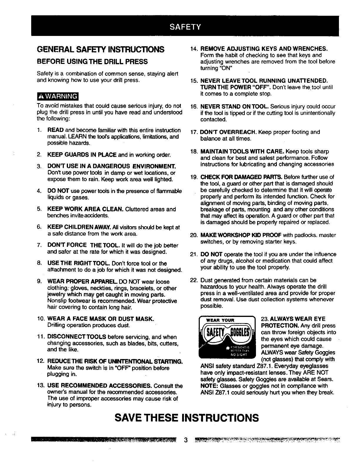
23. ALWAYS WEAR EYE
PROTECTION. Any drill press
can throw foreign objects into
the eyes which could cause
permanent eye damage.
ALWAYSwear SafetyGoggles
(not glasses) that comply with
ANSI safety standard Z87.1. Everyday eyeglasses
have only impact-resistant lenses. They ARE NOT
safety glasses. Safety Goggles are available at Sears.
NOTE: Glasses or goggles not in compliance with
ANSI Z87.1 could seriously hurt you when they break.
SAVE THESE INSTRUCTIONS
SPECIFIC SAFETY INSTRUCTIONS
FOR THE DRILL PRESS 14. SECURE WORK. Use clamps or a vise to hold the
work when practical. It's safer than usingyour hand
and it frees both hands to operate tool.
For your own safety, do not try to usa your drillpress
or plug it in untilit is completely assembled and installed
according to the instructions, and until you have read and
understood this instruction manual:
1, YOUR DRILL PRESS MUST BE BOLTED securely
to a workbench. In addition, if there is any tendency
for your drill press to move during certain operations,
bolt the workbench to the floor.
2,
3.
THIS DRILL PRESS is intended for use in dry
conditions, indoor use only.
WEAR EYE PROTECTION. USE face or dust mask
along with safety goggles if drilling operation is dusty.
USE ear protectors,especiallydudng extended periods
of operation.
4. DO NOT wear gloves, neckties, or loose clothing.
5. DO NOT try to drill material too small to be securely
held.
15.
16.
17.
18.
19.
20.
21.
6. ALWAYS keep hands out of the path of a drill bit.
Avoid awkward hand positions where asudden slip
could cause your hand to move into the ddll bit, 22.
DO NOT install or use any drill bit that exceeds
175 mm (7") in length or extends 150 mm (6") below
the chuck jaws. They can suddenly bend outward or
break.
7.
8. DO NOT USE wire wheels, routerbits, shaper cutters,
circle (fly) cutters, or rotary planers on thisddll press.
23.
9. WHEN cutting a large piece of material make sure it 24.
is fully SUldportedat the table height.
10. DO NOT perform any operation freehand. ALWAYS 25.
hold the workpiece firmly against the table so it will
not rock or twist. Use clamps or a vise for unstable
workpieces.
1f. MAKE SURE there are no nails or foreign objects in 26.
the part of the workpiece to be drilled. 27.
12. CLAMPWORKPIECE OR BRACE against the I_t
side of the columnto prevent rotation, ff it is too short
or the table is tilted, clamp solidly to the table and
use the fence provided.
WHEN using a drill press vise, always fasten to the
table.
MAKE SURE all clamps and locks are firmly
tightened before drilling.
SECURELY LOCK THE HEAD and table support to
the column, and the table to the table support before
operating the drill press.
NEVER turn your drill press on before cleadng the
table of all objects (tools, scraps of wood, etc.)
BEFORE STARTING the operation, jog the motor
switch to make sure the ddll bit does not wobble or
vibrate.
LET THE SPINDLE REACH FULL SPEED before
startingto ddll. If your drill press makes an unfamiliar
noise or if it vibrates excessively, stop immediately,
turn the drillpress off and unplug.Do not restartuntil
the problem is corrected.
DO NOT perform layout assembly or set up work on
the table while the drill press is in operation.
USE RECOMMENDED SPEED fordrill accessoryand
wotkpiecematerial.SEE INSTRUCTIONS that come
withthe accessory.
WHEN DRILLING large diameter holes, clamp the
workpiece firmly to the table. Otherwise, the bit may
grab and spin the workpieceat high speed. DO NOT
USE fly cutters or multiple-part hole cutters, as they
can come apart or become unbalanced in use.
MAKE SURE the spindle has come to a complete
stop before touching the workpiece.
TO AVOID INJURY from accidental starting, always
tum the switch"OFF" and unplugthe dnllpress before
installing or removing any accessory or attachment
or making any adjustment.
KEEP GUARDS IN PLACE and in working order.
USE ONLY SELF-EJECTING TYPE CHUCK.KEY as
provided with the drill press.
13. IFTHE WORKPIECE overhangs the table such that
it will fall or tip if not held, clamp it to the table or
provide auxiliary support. SAVE THESE INSTRUCTIONS
GROUNDING INSTRUCTIONS
IN THE EVENT OF A MALFUNCTION OR BREAKDOWN,
grounding provides a path of least resistance for electric
current and reduces the risk of electric shock. This tool
is equipped with an electdc cord that has an equipment.
grounding conductor and a grounding plug. The plug
MUST be plugged into a matching receptacle that is
properly installed and grounded in accordance with ALL
local codes and ordinances.
DO NOT MODIFYTHE PLUG PROVIDED. If it will notfit the
receptacle, have the proper receptacle installed by a
qualified electrician.
IMPROPER CONNECTION of the equipment grounding
conductor can result in risk of electric shock. The
conductor with the green insulation(with or withoutyellow
stripes) is the equipment grounding conductor. If repair
or replacement of the electric cord or plug is necessary,
DO NOT connect the equipment groundingconductor to
a live terminal.
CHECK with a qualified electrician or service personnel it
you do notcompletelyunderstandthe groundinginstructions,
or if you are notsure the tool is properly grounded.
USE ONLY 3-WIRE EXTENSION CORDS THAT HAVE
3-PRONG GROUNDING PLUGS AND 3-POLE
RECEPTACLES THAT ACCEPT THE TOOL'S PLUG.
REPAIR OR REPLACE DAMAGED OR WORN CORD
IMMEDIATELY.
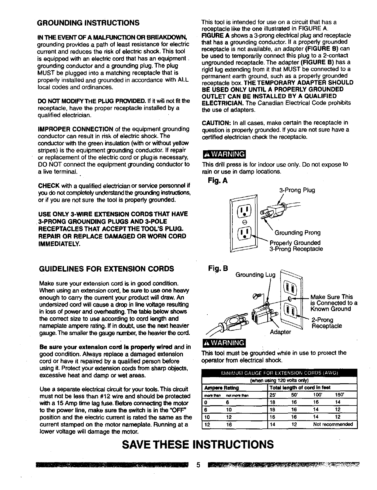
This tool is intended for use on a cimuit that has a
receptacle like the one illustrated in FIGURE A
RGURE A shows a 3-prong electrical plug and receptacle
that has a grounding conductor. If a properly grounded
receptacle is not available, an adapter (FIGURE B) can
be used to temporarily connect this plug to a 2-contact
ungrounded receptacle. The adapter (FIGURE B) has a
rigid lug extending from it that MUST be connected to a
permanent earth ground, such as a properly grounded
receptacle box. THE TEMPORARY ADAPTER SHOULD
BE USED ONLY UNTIL A PROPERLY GROUNDED
OUTLET CAN BE INSTALLED BY AQUALIFIED
ELECTRICIAN. The Canadian Electrical Code prohibits
the usa of adapters.
CAUTION: In all cases, make certain the receptacle in
question is propedy grounded.If you are not sure have a
certified electriciancheck the receptacle.
This ddll press is for indoor use only. Do not expose to
rein or use in damp locations.
Fig. A
3-Prong Plug
Prong
Properly Grounded
3-Prong Receptacle
GUIDELINES FOR EXTENSION CORDS
Make sure your extension cord is in good condition.
When using an extensioncord, be sure to use one heavy
enough to carry the current your product will drew. An
undersized cord will cause a drop in line voltage resulting
in loss of power and overheating.The table below shows
the correct size to usa according to cord length and
nameplate ampere rating.If indoubt, use the next heavier
gauge.The smaller the gauge number,the heavierfile cord.
Fig. B Grounding Lug I_
_ If is Connected toa
_:_ 1_'_L Known Ground
_1 .._ _---_- I["" 2-Prong
._ _"'-¢"___1"_v \_Receptacle
//f_'-'_ Adapter
Be sure your extension cord is properly wired and in
good condition. Always replace adamaged extension
cord or have it repaired by a qualified person before
using it. Protect your extensioncords from sharp objects,
excessive heat and damp or wet areas.
Use a separate electricalcircuitforyour tools.This cimuit
must not be less than #12 wire and should be protected
witha 15 Amp time lag fuse. Before connectingthe motor
to the power line, make sure the switch is in the "OFF"
position and the electdc current is rated the same as the
current stamped on the motor nameplate. Running at a
lower voltage will damage the motor.
This tool must be grounded while in use to protect the
operator from electrical shock.
(whenusing120 voltso_y)
Ampere R_Ing
m(_e _man noqmore than
0 6
6 10
10 12
12 16
Totallengthofcordln feet
25' 50' 100' 150'
18 16 16 14
18 16 14 12
16 16 14 12
14 !2 Notrecomrnended
SAVE THESE INSTRUCTIONS
AVAILABLE ACCESSORIES UNPACKING AND CHECKING
CONTENTS
Use only accessories recommended for this drill press.
Follow instructions that accompany accessories. Use of
improper accessories may cause hazards.
Visit your Sears Hardware Department or see the Sears
Power and Hand Tool Catalog for the following
accessories:
Drill bits
•Hold-Down and Guide
• Drill Press Vises
• Clamping Kit
If any part is missing or damaged, do not plug the drill
press in until the missing or damaged part is replaced,
and assembly is complete.
Carefully unpack the drill press and all its parts, and
compare against the list below.
To protect the drill press from moisture, a protective
coating has been applied to the machined surfaces.
Remove this coating with a soft cloth moistened with
kerosene or WD-40.
rT._kVlV/_,1-1_II_It"..]
Use only accessories designed for this drill press to avoid
injury from thrown broken parts or workpieces.
Sears may recommend other accessories not listed in
this manual. See your nearest Sears store or Power and
Hand Tool Catalog for other accessories.
Do not use any accessory unless you have completely
read the instruction or owner's manual for that accessory.
To avoid fire or toxic reaction, never use gasoline, naphtha,
acetone, lacquer thinner or similar highly volatile solvents
to clean the drill press.
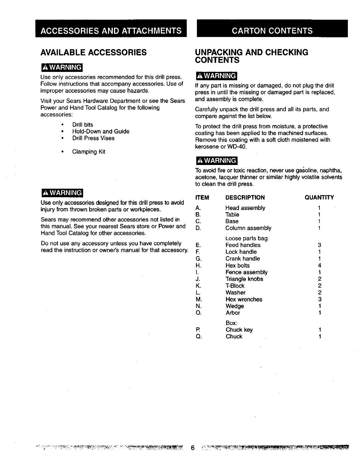
ITEM DESCRIPTION QUANTITY
A. Head assembly
B. Table
C. Base
D. Column assembly
Loose parts bag:
E. Feed handles
E Lock handle
G. Crank handle
H. Hex bolts
I. Fence assembly
J. Triangle knobs
K. T-Block
L. Washer
M. Hex wrenches
N. Wedge
O. Arbor
Box:
P. Chuck key
Q. Chuck
1
1
1
1
3
1
1
4
1
2
2
2
3
1
1

// o II
\JJl
D
8
E
r4_ =, 1
N0
}
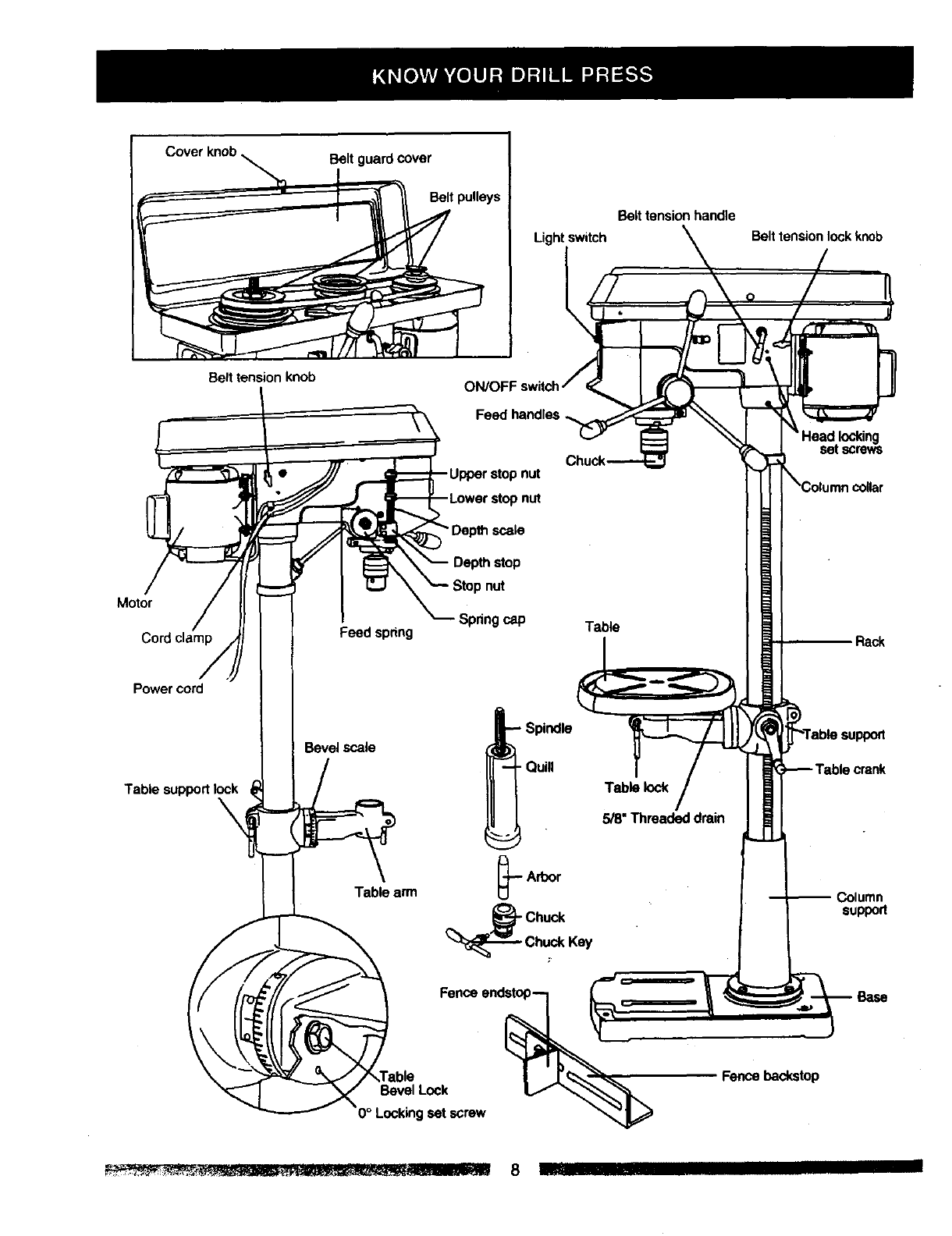
Belt guard cover
Belt pulleys
Light switch
LBelt tension handle
Belt tension lock knob
Bert tension knob ON/OFF
Motor
Cord clamp
Power cord
Table support lock
Feed spring
Bevel scale
Table arm
-UPper stop nut
nut
Depth stop
nut
-Spring cap
_pindle
Quill
Table
Table lock
5/8"Threadeddrain
set screws
Rack
,crank
Column
support
Bevel Lock
set screw
Fencebackstop
BASE- Supports the drill press. For additional stability,.
holesare provided in the base to bolt the drill press to
U_efloor.(See "Specific Safety Instructionsfor DriUPresses".)
BACKUP MATERIAL - A piec_eof scrap wood placed
betweenthe workpiece and table. The backup board
preventswood in the workpiece from splinteringwhen the
drillpasses through the backside of the workpiece. It also
preventsdrilling into the table top.
BELT GUARD ASSEMBLY -Covers the pulleys and belt
duringoperation of the drill press.
BELTTENSION - Refer to the =Assembly" Section,
"Installing and Tensioning Belt."
BELTTENSION HANDLE -Turn the handle clockwise to
applytension to belt, turn the handle counterclockwise
to release belt tension.
BELTTENSION LOCK KNOBS -Tightening the knobs
locksthe motor bracket support and the belt tension
handle,maintaining correct belt distance and tension.
BEVEL SCALE - Shows the degree of table tilt for bevel
operations.The scale is mounted on the side of the arm.
CHUCK - Holds the drill bit or other recommended
accessoryto perform desired operations.
CHUCK KEY - A self-ejecting chuck key which will pop
outof the chuck when you let go of it.This action is
designed to help prevent throwing of the chuck key from
thechuck when the power is turned "ON". Do not use
anyother key as a substitute;order a new one if damaged
orlost.
COLUMN - Connects the head, table, and base on a
one-piece tube for easy alignment and movement.
COLUMN COLLAR - Holds the rack to the column.
Rack remains movable in the collar to permit table
supportmovements.
COLUMN SUPPORT -Supports the column, guides the
rackand provides mounting holes for column to base.
DEPTHSCALE STOP NUTS - Lockthespindletothe
selecteddepth.
DEPTH SCALE - Indicates depth of hole being drilled.
DRILL BIT - The cutting tool used in the drill press to
make holes in a workpiece.
DRILL ON/OFF SWITCH - Has locking feature. This
feature is intended to help prevent unauthorized and
possiblehazardous use by children and others. Insert the
keyinto the switchto turn the drill press on.
DRILLING SPEED -Changed by placing the belt in any
of the steps (grooves) in the pulleys. See the Spindle
Speed Chart inside the belt guard.
FEED HANDLE - Moves the chuck up or down. If
necessary, one or two of the handles may be removed
whenever the workpiece is of such unusual shape that it
interferes with the handles.
FENCE - Attaches to the table to align the workpiece or
for fast rape"tdivedrilling.Removable. Remove fence when
it interferes with other drill press accessories.
HEAD LOCKS - Leeks the head to the column. ALWAYS
lockthe head in place while operating the drill press.
RACK - Combines with gear mechanism to provide easy
elevation of the table by the hand operated table crank.
REVOLUTION PER MINUTE (R.P.M.) -The number of
turns completed by a spinning object in one minute.
SPINDLE SPEED -The R.P.M. of the spindle.
SPRING CAP -Adjusts the quill spring tension.
TABLE SUPPORT LOCK -Tightening locksthe table
support to the column. Always have it locked in place
while operating the drill press.
TABLE - Provides a working surface to support the
workpiece.
TABLE ARM - Extends beyond the table support for
mounting and aligning the table.
TABLE BEVEL LOCK - Locks the table in any position
from 0° - 45°.
TABLE CRANK - Elevates and lowers the table. Turn
clockwise to elevate the table. Support lock must be
released before operating the crank.
TABLE LOCK - Locks the table after it is rotated to
various positions.
TABLE SUPPORT - Rides on the column to support the
table arm and table.
THREADED DRAIN (5/8") - Attach a 5/8" (pipe threaded)
metal pipe to the threaded opening for draining excess oil
into container. For a non-drainingsurface attach a threaded
metal plug. Pipe and plug not included.
WORKPIECE - Material being drilled.
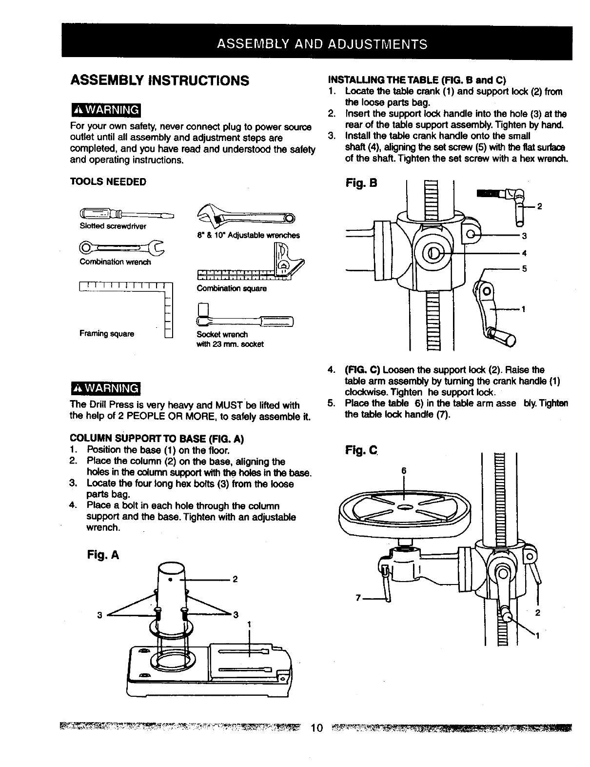
ASSEMBLY INSTRUCTIONS
For your own safety, never connect plug to power source
outlet until all assembly and adjustment steps are
completed, and you have read and understood the safety
and operating instructions.
TOOLS NEEDED
Slotted ,screwdriver
Combination wrench
L' '"
Framingsquare Socketwrench
with23 mm.socket
8" & 10" Adjustable v,l_mches
Combinationsquare
INSTALUNG THE TABLE (FIG. B and C)
1. Locate the table crank (1) and support lock (2) from
the loose parts beg.
2. Insert the support lock handle into the hole (3) at the
rear of the table support assembly. Tighten by hand.
3. Install the table crank handle onto the small
shaft (4), aligningthe set screw (5) withthe fiat surface
of the shaft. Tighten the set screw with a hex wrench.
Fig. B
3
4
The Ddll Press is very heavy and MUSTbe lifted with
the help of 2 PEOPLE OR MORE, to safely assemble it.
4. (RG, C) Loosen the support lock (2). Raise the
table arm assembly by tuming the crank handle (1)
clockwise.Tighten he support lock.
5. Place the table 6) in the table arm asse bly. Tighten
the table lock handle (7).
COLUMN SUPPOFITTO BASE (FIG. A)
1. Posltion the base (1) on the floor. Fig.C°
2. Place the column (2) on the base, aligning the
holes in the column supportwith the holes in the base.
3. Locate the four long hex bolts (3) from the loose
parts bag.
4, Place a bolt in each hole through the column
support and the base, Tighten with an adjustable
w:nch.
Fig. A
•2
i
I
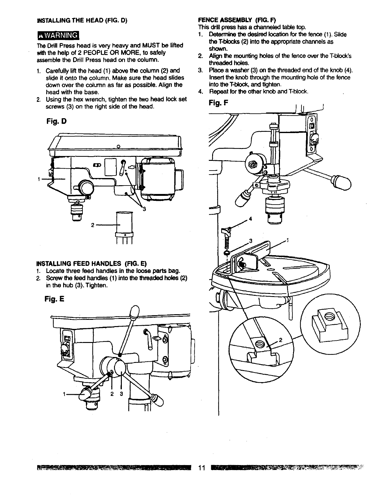
INSTALLINGTHE HEAD (FIG. D)
TheDrill Press head is very heavy and MUST be lifted
withthe help of 2 PEOPLE OR MORE, to safely
assemblethe Drill Press head on the column.
1. Carefully liftthe head (1) above the column (2) and
slide it onto the column. Make sure the head slides
down over the column as far as possible.Align the
head with the base.
2, Using the hex wrench, tighten the two head lock set
screws (3) on the right side of the head.
Fig. D
1
FENCE ASSEMBLY (RG. F)
This drillpress has a channeled tabletop.
1. Determine the desiredlocationfor the fenco (1). Slide
the T-blocks(2) into_appropriatechannels as
shown.
2. Align the mountingholes of the fence overthe T-block's
threaded holes.
3. Place a washer (3) on the threaded end of the knob (4).
Insert the knobthrough the mountinghole of the fence
into the T-block,and tighten.
4. Repeat forthe other knob andT-block.
Fig. F
INSTALLING FEED HANDLES (FIG. E)
1. Locate three feed handles in the loose parts bag.
2. Screw the feed handles (1) into the threaded holss (2)
in the hub (3). Tighten.
Fig. E
2 3
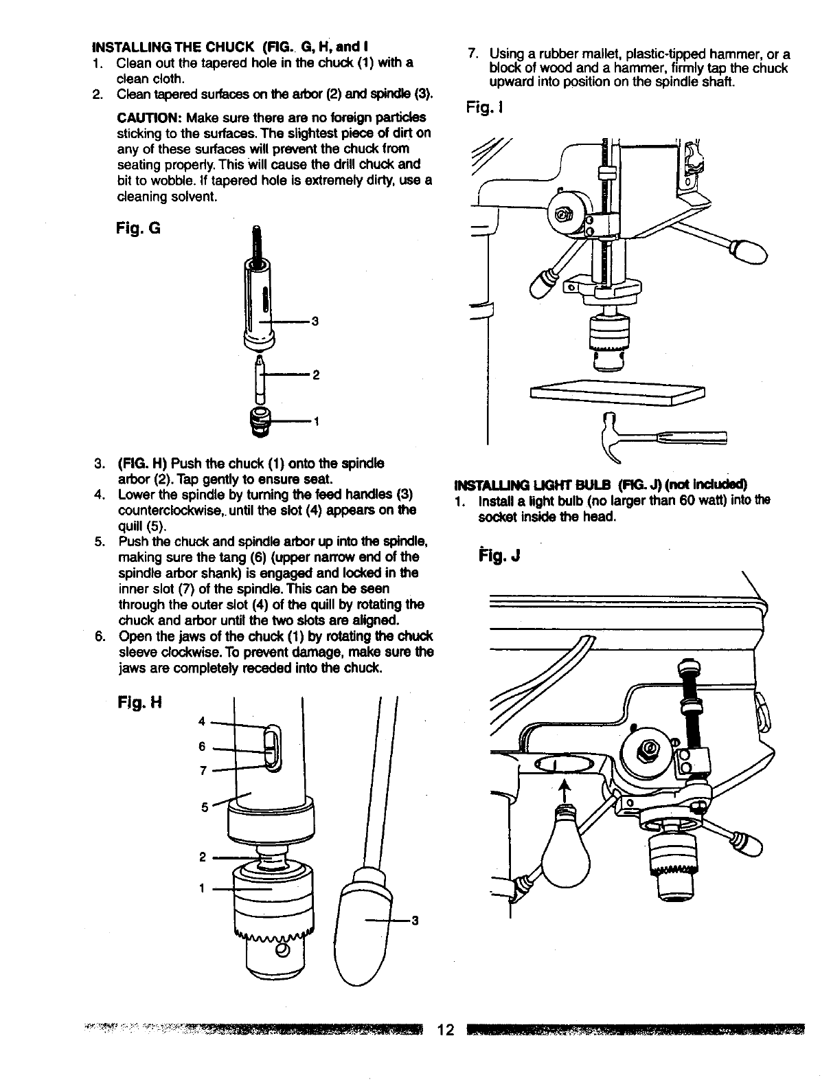
INSTALLINGTHECHUCK(RG. G,H,andI
1, Cleanoutthetaperedholeinthechuck(1)witha
clean cloth.
2. Clean tapered surfaceson the ad_or(2) and spindle(3).
CAUTION: Make sure there are no foreign particles
stickingto the surfaces. The slightest piece of dirt on
any of these surfaces will prevent the chuck from
seating properly.This will cause the drill chuck and
bit to wobble. If tapered hole is extremely dirty, use a
cleaning solvent.
Fig. G
3. (FIG. H) Push the chuck (1) onto the spindle
arbor (2). Tap gently to ensure seat.
4. Lower the spindle by turning the feed handles (3)
counterclockwise,,until the slot (4) appears on the
quill (5).
5. Push the chuck and spindle arbor up intothe spindle,
making sure the tang (6) (upper narrow end of the
spindle arbor shank) is engaged and locked in the
inner slot (7) of the spindle. This can be seen
through the outer slot (4) of the quill by rotating the
chuck and arbor until the two slots are aligned.
6. Open the jaws of the chuck (1) by rotating the chuck
sleeve clockwise.To prevent damage, make sure the
jaws are completely receded into the chuck.
Fig. H
7. Using arubber mallet, plastic-tipped hammer, or a
block of wood and a hammer, firmly tap the chuck
upward into positionon the spindle shaft.
Fig. I
n ST J.U Suc rreuus(RG.J)(not
1. Install a light bulb (no larger than 60 watt) intothe
socket inside the head.
Fig. J
DRILL PRESS ADJUSTMENTS
CAUTION: All the adjustments for the operation of the
drillpresshave been completed at the factory, Due to
normalwear and use, some occasional readjustments
maybe nesessary.
IP_WkrlVl_,1-'l_l_'l
Topreventpe_scoalinjury, always disconnectthe plugfrom
•epowersourcewhen making any adjustments.
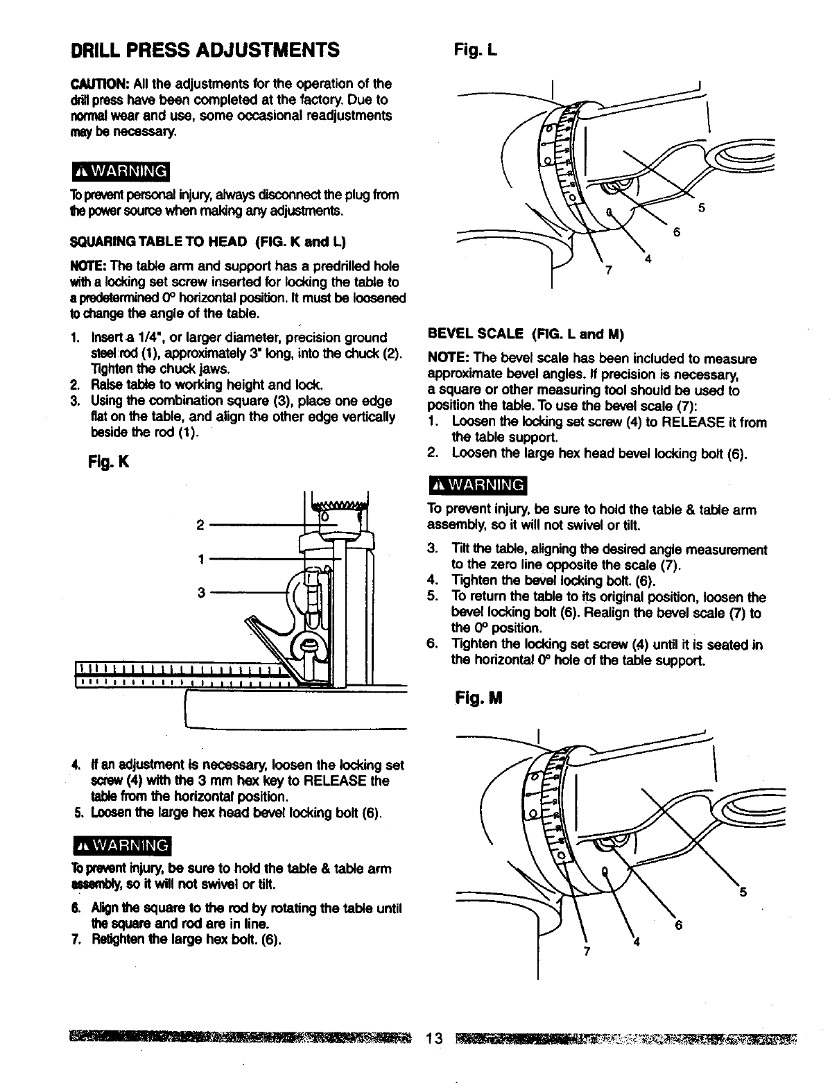
SQUARINGTABLE TO HEAD (FIG. K and L)
NOTE:The table arm and support has a predrilled hole
witha lockingset screw inserted for locking the tab_ to
s predetermined0° horizontalposition.It must be loosened
tochangethe angle of the table.
1. Inserts 114",or larger diameter, precision ground
steel:rod(1), approximately3" long, into the chuck (2).
Tightenthe chuck jaws.
2. Raise table to working height and lock.
3. Usingthe combination square (3), place one edge
fiaton the table, and align the other edge vertically
besidethe rod (1).
Fig. K
n_krAvl_,1-1_ll_el
r| |i iiit l i | i liii iii
L_ III I I I I I I I I_
4. If an adjustment is necessary, loosen the locking set
screw(4) with the 3 mm he)( key to RELEASE the
tablefrom the horizontal position.
5. Loosenthe large hex head bevel locking bolt (6).
_vH,_,]iiLql_[9
Topreventinjury,be sure to hold the table & table arm
mssmbly,so it will not swivel or tilt.
6. Nign the square to the rod by rotating the table until
the square and rod are in line.
7. Relightanthe large hex bolt. (6).
Fig. L
4
7
BEVEL SCALE (RG. L and M)
NOTE: The bevel scale has been included to measure
approximate bevel angles. If precision is necessary,
a square or other msasudng tool should be used to
positionthe table. To use the bevel scale (7):
1. Loosen the lockingset screw (4) to RELEASE it from
the table support.
2. Loosen the large hex head bevel locking bolt (6).
To prevent injury, be sure to hold the table & table arm
assembly, so it will not swivel or tilt.
3. Tilt the table, aligning the desired angle measurement
to the zero line opposite the scale (7).
4. Tighten the bevel locking bolt. (6).
5. To return the table to its original position, loosen the
bevel locking bolt (6). Realign the bevel scale (7) to
the 0° position.
6. Tighten the locking set screw (#,) until it is seated in
the horizontal 0° hole of the table support.
Fig. M
6
7
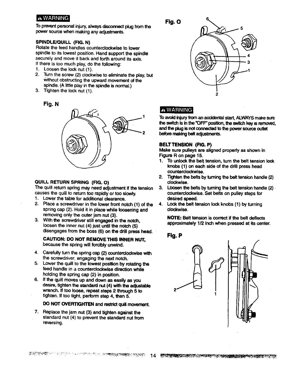
Toprevent personalinjury, always disconnectplugfrom the
power source when making any adjustments.
SPINDLE/QUILL (FIG. N)
Rotate the feed handles counterclockwise to lower
spindle to its lowest position. Hand support the spindle
securely and move it back and forth around its axis.
If there is too much play, do the following:
1. Loosen the lock nut (1).
2. Turn the screw (2) clockwise to eliminate the play, but
Without obstructingthe upward movement of the
spindle.(A littleplay in the spindle is normal.)
3. Tighten the lock nut (1).
Fig. N mlW_Kql_
QUILL RETURN SPRING (RG. O)
The quill return spring may need adjustment if the tension
causes the quill to return too rapidly or too slowly.
1. Lower the table for additional clearance.
2. Place a screwdriver in the lower front notch (1) of the
spring cap (2). Hold it in place while loosening and
removing only the outer jam nut (3).
3, With the screwdriver stillengaged in the notch,
loosen the inner nut (4) just untilthe notch (5)
disengages from the boas (6) on the ddll press head.
CAUTION: DO NOT REMOVETHIS INNER NUT,
because the spring will forcibly unwind.
4. Carefully turn the spring cap (2) counterclockwisewith
the screwdriver, engaging the next notch.
5, Lower the quill to the lowest position by rotating the
feed handle in a counterclockwise direction while
holding the spring cap (2) in po6ition.
6. If the quill moves up and down as easily as you
desire, tighten the standard nut (4) with the adjustable
wrench. If too loose, repeat steps 2 through 5 to
tighten. If too tight, perform step 4, then 5.
DO NOT OVERTIGHTEN and restr_ quill movement.
7. Replace the jam nut (3) and tighten against the
standard nut (4) to prevent the standard nut from
reversing.
Fig. O
2
To avoidinjuryfroman accidentalstart,ALWAYSmake sure
the switchis inthe "OFF" position,the sw#chkeymremoved,
and the plug is notconnestadto the powersource outlet
hence rce_ t_ ad]tmCmants.
BELTTENSION (RG. P)
Make sure pulleys are aligned properly as shown in
Figure R on page 15.
1. To unlock the belt tension, turn the belt tension lock
knobs (1) on each side of the ddll press head
counterclockwise.
2. T'_fen the bolts by tuming the belt tensmnhandle (2)
clockwise.
3. loosen the bolts by tuming the belt tensionhandle (2)
counterclockwise.Set belts on pulley steps for
desired speed.
4. Lock the belt tension lock knobs (1) by turning
clockwise.
NOTE: Belt tension is correct if the belt deflects
approximately 1/2 inch when pressed at its center.
Fig. P
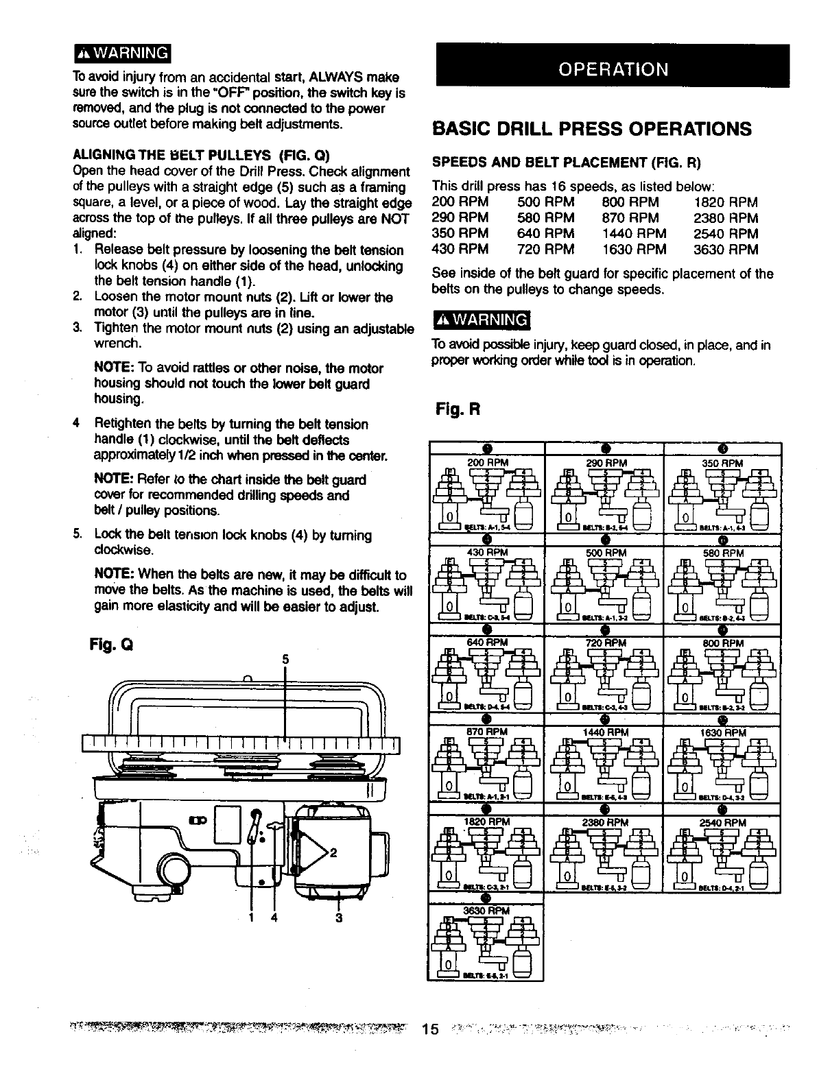
Toavoid injury from an accidental start, ALWAYS make
surethe switch is inthe =OFF" position, the switch key is
removed,and the plug is not connected to the power
sourceoutlet before making belt adjustments
ALIGNINGTHE BELT PULLEYS (RG. Q)
Openthe head cover of the Drill Press Check alignment
ofthe pulleys with a straight edge (5) such as a framing
square,a level, or a piece of wood Lay the straight edge
acrossthe top of the pulleys If all three pulleys are NOT
aligned:
1Release belt pressure by loosening the belt tension
lockknobs (4) on either side of the head, unlocking
the belt tension handle (1)
2 Loosen the motor mount nuts (2) Lift or lower the
motor (3) until the pulleys are in line.
3 Tighten the motor mount nuts (2) using an adjustable
wrench.
.
NOTE: To avoid rattles or other noise, the motor
housing should not touch the lower belt guard
housing.
Retighten the belts by turning the belt tension
handle (1) clockwise, until the belt deflects
approximately1F2inch when pressed inthe center.
NOTE: Refer t;othe chart inside the belt guard
coverfor recommended drillingspeeds and
belt/pulley positions.
Lockthe belt tens=onlock knobs (4) by tuming
clockwise
NOTE: When the belts are new, it may be difficultto
move the belts As the machine is used, the belts will
gain more elasticity and will be easier to adjust
Fig. Q
1 4 3
BASIC DRILL PRESS OPERATIONS
SPEEDS AND BELT PLACEMENT (FIG. R)
This drill press has 16 speeds, as listed below:
200 RPM 500 RPM 800 RPM 1820 RPM
290 RPM 580 RPM 870 RPM 2380 RPM
350 RPM 640 RPM 1440 RPM 2540 RPM
430 RPM 720 RPM 1630 RPM 3630 RPM
See inside of the belt guard for specific placement of the
belts on the pulleys to change speeds
To avoidpossible injury,keep guard closed, in place, and in
proper workingorderwhile tool is in operation
Fig. R
9
200 RPM
0
430 RPM
O
64O RPM
O
870 RPM
9
1820 RPM
0
ip
290 RPM
IP
500 RPM
9
72ORPM
tp
1441) RPM
9
2380 RPM
@
350 RPM
9
580 RPM
9
800 RPM
9
1630 RPM
tp
2540 RPM
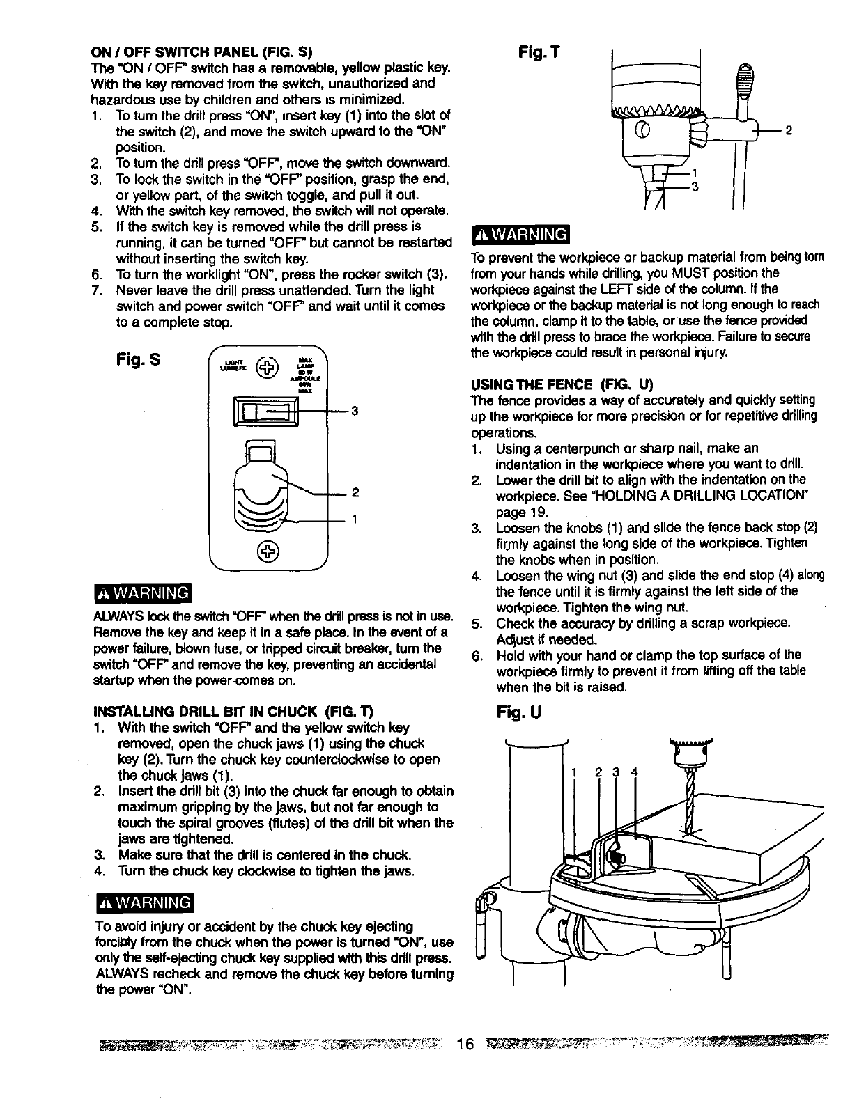
ON /OFF SWITCH PANEL (FIG. S)
The "ON /OFF" switch has a removable, yellow plastic key.
With the key removed from the switch, unauthorized and
hazardous use by children and others is minimized.
1. To turn the drill press "ON", insert key (1) into the slot of
the switch (2), and move the switch upward to the "ON"
position.
2. To turn the drill press"OFF", move the switchdownward.
3. To lock the switch in the =OFF" position, grasp the end,
or yellow part, of the switchtoggle, and pull it out.
4. W=ththe switch key removed,the switch will not operate.
5. If the switch key is removed while the ddit press is
running, it can be turned =OFF" but cannot be restarted
without inserting the switch key.
6. To turn the worklight"ON", press the rocker switch (3).
7. Never leave the drill press unattended. "rumthe light
switch and power switch "OFF" and wait until it comes
to a complete stop.
Fig. S @=.
=--
@
_3
_2
B1
tRg_
ALWAYSlockthe switch=OFF"whenthe drillpressis notinuse.
Remove the key and keep it in asafe place. In the event of a
power failure, blown fuse, or tripped circuitbreaker, turn the
switch =OFF" and removethe key,preventingan accidental
sfartup when the power comes on.
INSTALLING DRILL BIT IN CHUCK (RG. 1")
1. With the switch "OFF" and the yellow switch key
removed, open the chuck jaws (1) using the chuck
key (2). Turn the chuck key counterclockwise to open
the chuck jaws (1).
2, Insert the drill bit (3) into the chuck far enough to obtain
maximum gripping by the jaws, but not far enough to
touch the spiral grooves (flutes) of the drill bit when the
jaws are tightened.
3. Make sure that the drill is centered in the chuck.
4. Turn the chuck key clockwise to tighten the jaws.
To avoid injury or accident by the chuck key ejecting
forcibly from the chuck when the power is turned "ON", use
only the self-ejecting chuck key supplied with this ddll press.
ALWAYS recheck and remove the chuck key before turning
the power "ON".
Fig. T
_2
To prevent the workpiece or backup material from beingtorn
from your bands while drilling,you MUST positionthe
workpieceagainst the LEFT side of the column. If the
workpieceor the backup material is not longenough to reach
the column, clamp it to the table, oruse the fence provided
withthe drill pressto brace the workpiece.Failureto secure
the workpiscacould result in personal injury.
USING THE FENCE (FIG. U)
The fence provides a way of accurately and quicklysetting
up the workpiece for more precision or for repetitivedrilling
operations.
1. Using a centerpunch or sharp nail, make an
indentation in the workpiece where you want to drill.
2. Lower the drillbit to align with the indentationon the
workpiece. See =HOLDING A DRILLING LOCATION"
page 19.
3. Loosen the knobs (1) and slide the fence back stop(2)
firmly against the longside of the workpiece.Tighten
the knobs when in position.
4. Loosen the wing nut (3) and slide the end stop (4) along
the fence untilit is firmly against the left side of the
workpiece. Tighten the wing nut.
5. Check the accuracy by drillinga scrap workpiece.
Adjust if needed.
6. Hold with your hand or clamp the top surface of the
workpiece firmly to prevent it from liftingoff the table
when the bit is raised.
Fig. U
234

DRILLING TO A SPECIRC DEPTH (RG. V)
Drillinga blind hole (not all the way through workpiece)
to agiven depth can be done two ways:
Workplece method
1. Mark the depth (1) of the hole on the side of the
workpiece.
2. With the switch"OFF", bring the drill bit down untilthe
tip is even with the mark.
3. Hold the feed handle (2) at this position.
4. Spinthe lowernut (3) down to contactthe depthstop (4)
on the head.
5. Spin the upper nut (5) down and tighten against the
lower nut (3).
6. The drill bitwill now stop after travelingthe distance
marked on the workpiece.
Depth scale method
NOTE: With the chuck up the tip of the ddll bit must be
just slightly above the top of the workpiece.
1. With the switch"OFF', tum the feed handle (2) untilthe
depth stop(4) pointsto the desireddepth on the depth
scale (6) and hold the feed handle in that position.
2. Spin the lower nut (3) down to contact the depth
stop (4).
3. Spin the upper nut(5) againstthe lower nut(3) and
tighten.
4. The drill bitwill stop after travelingthe distanceselected
on the depth scale.
Fig. V
LOCKING THE CHUCK AT THE DESIRED DEPTH
(RG. W)
1. With the switch"OFF', turn the feed handles untilthe
chuck(1) is at the desireddepth. Holdthe feed handles
at this position.
2. Turnthe stop nut(2), locatedunderthe depth stop(3),
ceunterclockwise and upwards until it is against the
depth stop.
3. The chuckwill now be held at this position when the
feed handles are released.
REMOVING CHUCK AND ARBOR (FIG. X)
1. With the switchOFF, edjust the dopthstop nut (1) to
holdthe drillat a depth of three inches.(See instructions
for =LOCKING CHUCK AT DESIRED DEPTH").
2. Align the key holes in the spindle (2) and quill (3) by
rotating the chuck by hand.
3. Insert the key wedge (4) into the key holes (2 & 3).
4. Tap the key wedge (4) lightlywith a plastic tipped
hammer, until the chuck and arbor fall out of the
spindle.
NOTE: Place one hand below the chuckto catch it
when it falls out.
Fig. X
BASIC OPERATION INSTRUCTIONS
To get the best results and minimize the likelihoodof
personal injury,follow these instructionsfor operating your
drill press.
For your own safety, always observe the SAFETY
INSTRUCTIONS listed here and on pages 3, 4, and 5
of the instruction manual.
YOUR PROTECTION
5.
6.
7.
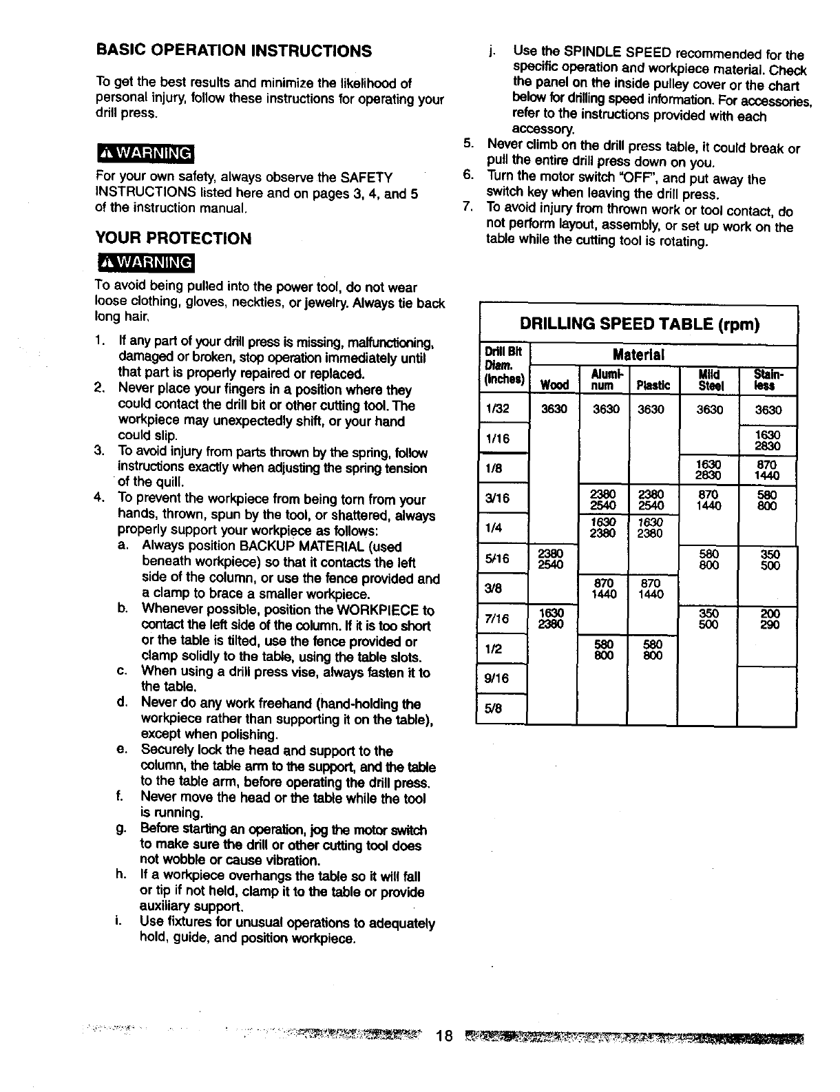
j. Use the SPINDLE SPEED recommended for the
specific operation and workpiece material. Check
the panel on the inside pulley cover or the chart
belowfor drillingspeed information. For accessories,
refer to the instructions provided with each
accessory.
Never climb or*the drill press table, it could break or
pull the entire drill press down on you.
Turn the motor switch =OFF', and put away the
switch key when leaving the drill press.
To avoid injury from thrown work or tool contact, do
not perform layout, assembly, or set up work on the
table while the cutting tool is rotating.
To avoid being pulled into the power t0ol, do not wear
loose clothing, gloves, neckties, or jewelry. Always tie back
long hair,
1,
2.
.
4.
If any part of yourdrill press is missing,maffunctioning, DrillBit
damaged or broken, stop operationimmediately until Diam.
that part is propedy repaired or replaced, i (inches)
Never place your fingers in apositionwhere they
could contact the drill bit or other cutting tool. The 1132
workpiece may unexpectedly shift, or your hand
could slip. 1/16
To avoid injury from parts thrown bythe spring,follow
instructionsexactly when adjusting the springtension 1/8
of the quill.
To prevent the workpiece from being tom from your 3/16
hands, thrown, spun by the tool, or shattered, always
properly support your workpiece as follows: 114
a. Always position BACKUP MATERIAL (used
beneath workpiece) so that it contacts the left 5/16
side of the column, or use the fence provided and 3/8
a clamp to brace a smaller workpiece.
b. Whenever possible, positionthe WORKPIECE to 7/16
contact the left side of the column. If it is too short
or the table is tilted, use the fence provided or 1/2
clamp solidly to the table, using the table slots.
c. When using a drill press vise, always fasten it to 9/16
the table.
d. Never do any work freehand (hand-holding the 5/8
workpiece rather than supporting it on the table),
except when polishing.
e. Securely lockthe head and support to the
column, the table arm to the support,and the table
to the table arm, before operating the drill press.
f. Never move the head or the table while the tool
is running.
g. Before startingan operatico,_ogthe motor switch
to make sure the drill or other cuttingtool does
not wobble or cause vibration.
h. If a workpiece overhangs the table so it will fall
or tip if not held, clamp it to the table or provide
auxiliary support.
LUse fixtures for unusual operations to adequately
hold, guide, and position workpiece.
DRILLING SPEED TABLE (rpm)
Material
Wood num Plastic
3630 3630 3630
238O
254O
1630
2380
2'38O 2380
2540 2540
1630 1630
2380 2380
870 870
1440 1440
580 580
8OO 800
M|!d Stain-
Steel less
363O 3630
1630
283O
1630 87O
2830 1440
870 580
1440 8OO
58O 350
8O0 5OO
35O 200
50O 290
............................ ..... 18 ___ ......
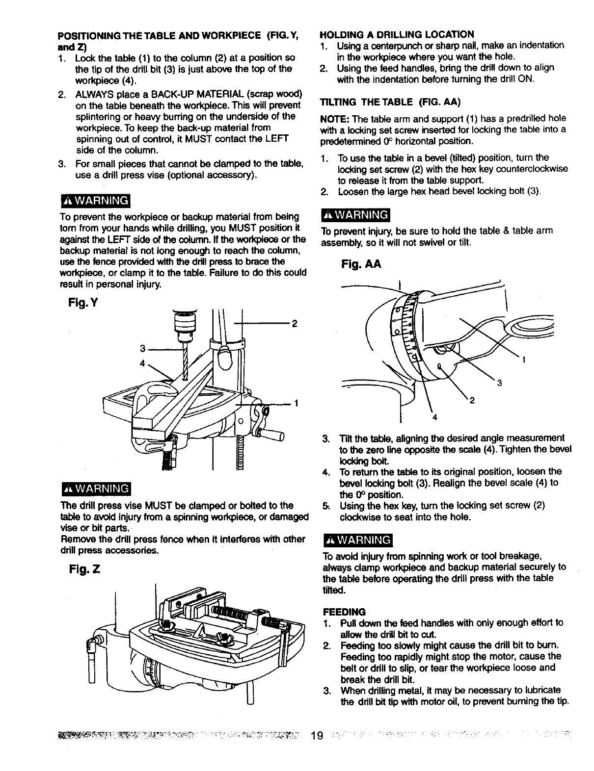
POSITIONING THE TABLE ANDWORKPIECE (FIG.Y,
and Z)
1. Lock the table (I) to the column (2) at aposition so
the tip of the drill bit (3) is just above the top of the
workpiece (4).
2. ALWAYS place a SACK-UP MATERIAL (scrap wood)
on the table beneath the workpiece. This will prevent
splintering or heavy burring on the underside of the
workpiece. To keep the beck-up material from
spinning out of control, it MUST contact the LEFT
side of the column.
3. For small pieces that cannot be clamped to the table,
use a drill press vise (optional accessory).
fRgf/_qK_
To prevent the workpiece or beckup material from being
tom from your hands while drilling, you MUST position it
against the LEFT side of the column,ffthe workpisce or the
beckup matedal is not long enough to reach the column,
use the fence providedwith the ddUpress to brace the
workpiece, or clamp it to the table. Failure to do this could
result in personal injury.
Fig.Y
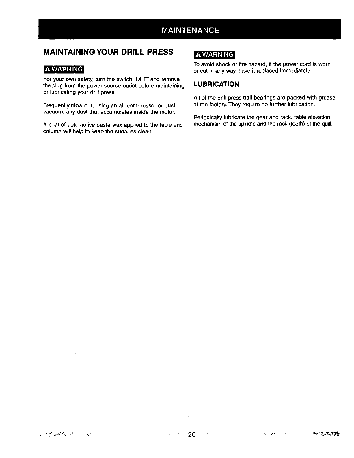
R_gf/i1_Kqi_e
The drill press vise MUST be clamped or bolted to the
table to avoid injury from a spinningworkpiece, or damaged
vise or bit parts.
Remove the ddll press fence when it interferes with other
drill press accessories.
Fig. Z
HOLDING A DRILLING LOCATION
1. Usinga centerpunch or sharp nail, make an indentation
in the workpiece where you want the hole.
2. Using the feed handles, bang the ddll down to align
withthe indentation before turning the drill ON,
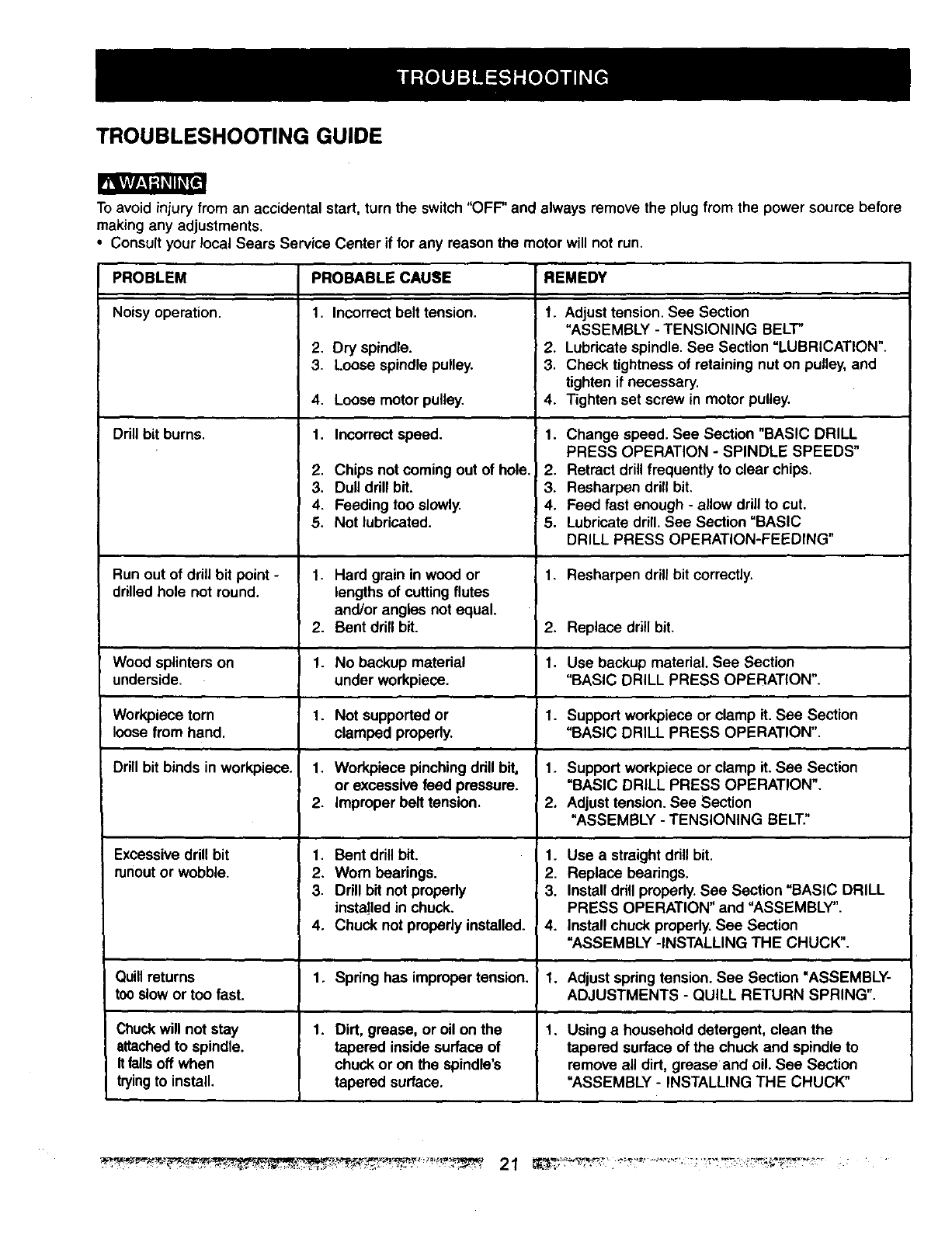
TILTING THETABLE (FIG. AA)
NOTE: The table arm and support (1) has apredrilled hole
with a locking set screw inserted for lockingthe table into a
predetermined 0° horizontalposition.
1. To use the table in a bevel (tilted) position,turn the
lockingset screw (2) with the hex key counterclockwise
to release it fromthe table support.
2. Loosen the large hex head bevel locking bolt (3).
To prevent injury,be sure to hold the table & table arm
assembly, so it will not swivel or tilt.
Fig. AA
3
2
4
3. Tilt the table, aligningthe desired angle measurement
to the zero line opposite the ,scale(4). Tighten the bevel
locking bolt.
4. To return the table to its original position, loosen the
bevel locking bolt (3). Realign the bevel scale (4) to
the 0° position.
&Using the hex key, turn the locking set screw (2)
clockwise to seat into the hole.
To avoid injury from spinning work or tool breakage,
always clamp workpieco end backup material securely to
the table before operating the ddU press with the table
tilted.
FEEDING
1. Pull down the feed handles with only enough effort to
allow the ddll bitto cut.
2. Feeding too slowly might cause the drill bit to burn.
Feeding too rapidly might stop the motor, cause the
belt or ddll to slip, or tear the workpiece loose and
break the ddll bit.
3, When ddlling metal, it may be necessary to lubricate
ttm drill bittip with motor oil, to prevent burningthe tip.
MAINTAINING YOUR DRILL PRESS
mL_ri1_]_qlLEe]
For your own safety, turn the switch "OFF' and remove
the plug from the power source outlet before maintaining
or lubricating your drill press.
Frequently blow out, using an air compressor or dust
vacuum, any dust that accumulates inside the motor.
Acoat of automotive paste wax applied to the table and
column will help to keep the surfaces clean.
To avoid shock or fire hazard, if the power cord is worn
or cut in any way, have it replaced immediately.
LUBRICATION
All of the drill press ball bearings are packed with grease
at the factory. They require no further lubrication.
Periodically lubricate the gear and rack, table elevation
mechanism of the spindleand the rack (teeth) of the quill.
TROUBLESHOOTING GUIDE
To avoid injury from an accidental start, turn the switch "OFF" and always remove the plug from the power source before
making any adjustments.
•Consult your local Sears Service Center if for any reason the motor will not run.
PROBLEM PROBABLE CAUSE REMEDY
Noisy operation. 1. Adjust tension. See Section
"ASSEMBLY - TENSIONING BELT"
2. Lubricate spindle. See Section "LUBRICATION".
3. Check tightness of retaining nut on pulley, and
tighten if necessary.
4. Tighten set screw in motor pulley.
Ddll bit burns. 1.
Run out of ddll bit point -
drilled hole not round.
Wood splinters on
underside.
Workpiece torn
loose from hand.
Drill bit binds in workpiece.
Excessive drill bit
runoutor wobble.
Quillreturns
too slow or too fast.
Chuck will not stay
attachedto spindle.
It falls off when
trying to install.
1. Incorrect belt tension.
2. Dry spindle.
3. Loose spindle pulley.
4. Loose motor pulley.
1. Incorrect speed.
2. Chips not coming out of hole.
3. Dull drill bit.
4. Feeding too slowly.
5. Not lubricated.
1. Hard grain in wood or
lengths of cuttingflutes
and/or angles not equal.
2. Bent drill bit.
1. No backup material
under workpiece.
1. Not supported or
clamped properly.
1, Workpiece pinching ddll bit,
or excessive feed pressure.
2. improper belt tension.
1. Bent drill bit.
2. Worn bearings.
3. Drill bit not propedy
installed in chuck.
4. Chuck not propedy installed.
1. Spring has improper tension.
1. Dirt, grease, or oil on the
tapered inside surface of
chuck or on the spindle's
tapered surface.
Change speed. See Section "BASIC DRILL
PRESS OPERATION -SPINDLE SPEEDS"
I2. Retract drillfrequently to clear chips.
3. Resharpen drill bit.
4. Feed fast enough - allow drill to cut.
5. Lubricate drill. See Section "BASIC
DRILL PRESS OPERATION-FEEDING"
1. Resharpen drill bit correctly.
2. Replace drill bit.
1. Use backup material. See Section
"BASIC DRILL PRESS OPERATION".
1. Support workpiece or clamp it. See Section
"BASIC DRILL PRESS OPERATION".
1. Support workpiece or clamp it. See Section
"BASIC DRILL PRESS OPERATION".
2. Adjust tension. See Section
"ASSEMBLY - TENSIONING BELT"
1. Use a straight drill bit.
2. Replace bearings.
3. Install ddll properly. See Section "BASIC DRILL
PRESS OPERATION" and "ASSEMBLY".
4. Install chuck properly. See Section
"ASSEMBLY -INSTALLING THE CHUCK".
1. Adjust spdng tension. See Section "ASSEMBLY-
ADJUSTMENTS - QUILL RETURN SPRING".
1. Using a household detergent, clean the
tapered surface of the chuck and spindle to
remove all dirt, grease and oil. See Section
"ASSEMBLY - INSTALLING THE CHUCK"
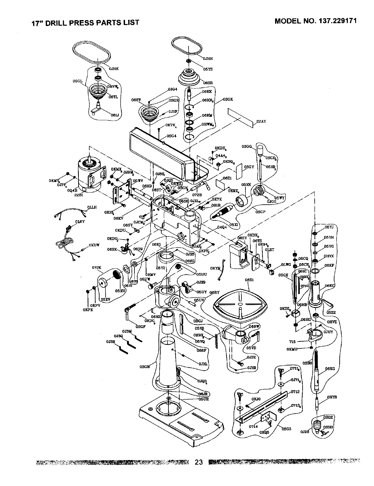
17" DRILL PRESS PARTS LIST MODEL NO. 137.229171
When servicing use only CRAFTSMAN replacement parts. Use of any other parts may create a HAZARD or cause
product damage,
Any attempt to repair or replace electrical parts on this Drill Press may create a HAZARD unless repair is done by a
qualified service technician. Repair service is available at your nearest Sears Service Center.
Always order by PART NUMBER, not by key number.
Key Description Size Qty. Key Description Size Qty.
0SUE BASE C_SY SWITCH BOX 1
0SGB COLUNM ASS'Y OKDK CR. RE. PAN HD. SCREW iS'O.8-1B 2
0JQO HEX. HD. BOLT M10"1.5_40 OSG4 PULLEY COVER ASS'Y 1
06RY TABLE BRACKET ASS'Y OSGL CENTER PULLEY ASS'Y 1
05UW WORM OJHK V-BELT 1
05UY CRANK HANDLE ASS'Y OJSF FLAT WASHER 4
0SVB TILT)NG SCALE 0KPX HEX. NUT 1/2"20 T=6.5 2
06RZ CENTER(NG SCALE 04A4 CLAMP-CORD 3
OSGF COLUMN LOCK HANDLE OKDH CR. RE. PAN HD. SCREW MB'O 5.8 3
OBVD TABLE LOCK HANDLE 061R CHUCK KEY HOLDER 1
(_$1 TABLE 0JHH V-BELT 1
05VQ RACK CBTS SWITCH COVER 1
06K1 RACK RiNG ASS'Y 0Kg4 CR RE, TRUSS HD, TAPPING SCREV M5"12-16 2
O6S9 HEAD ASS'Y CBKV MOTOR ROD 1
0JXL HEX, SOC SET SCREW M10"1 5-12 OJCM SPRING PiN 2
072B HANDLE SHIFTER 062X WARNING LABEL 1
05WL MOTOR BAR SHIFTER ASS'Y 22B1 MOTOR LABEL 1
06K9 MOTOR ROD 22AY SPEED DIAGRAM 1
OSGN SHIFTER BOLT 04Q4 STICKER 1
05WV MOTOR BASE OSGY TRADE-MARK LABEL
OJ9M SPRING WASHER "_1/'Z'
1
0KgX DRIVE SCREW _p2.3-5 4
OKMX HEX. NUT M12"1.75 T=I
OSGP HUB ASS'Y
OSGG HANDLE BAR ASS'Y
0GXK SCALE RING
0VJK SPRING CAP ASS'Y
05Y1 SPR(NG RETAINER
0_Y2 QUILL SET SCREW M10"1.5-28
OKMV HEX. NUT M10*I.BT---8
BSB8 SPINDLE ASS"(
OK9X DRIVE SCREW _ 2.3_5
OSG3 HARDWARE BAG AES'Y
0711 LOCK KNOB
0J7J FLAT WASHER 348"1 5/32-7/_
0712 PARALLEL BRACKET
0713 SLIDE PLATE
OKJO CAP HD. SQ.NECK BOLT M6"1.0-16
0714 PLATE
OKQS WING NUT MBX1.0
2
1
2
2
1
2
1
1
1
OSGK DRIVING SLEEVE ASS'Y
CBYS PULLEY SET NUT
CBSR SPINDLE PULLEY
OHY8 DRILLING ARBOR
0J28 CHUCKS KEY
OSGZ CHUCK
OSHO CHUCK KEY
0_7-2 WEDGE SHIFTER
0Q4B MOTOR
0K18 HEX. HD. SCREW AND WASHER M*1,25
0J7F FLAT WASHER 5/16"7/8-5/64
OKMY HEX. NUT M8"I .25 , T-_
06ST MOTOR PULLEY ASB'Y
0JG4 PARALLEL KEy
(_SV CLAMp-CORD
OKUW TERMINAL
0LWG ROCKER SWITCH
OBSK BULB SOCKET ASS'Y 1
OKFF DR. RE. PAN HD. SCREW M5*O.8_ 2
OJAF EXTERNAL TOOTH LOCK WASHER 2
OKDZ CR RE. PAN HD. SCREW (- " +) M6"1 0"35 2
06HB PLUNGER HOUSING 1
OKMU HEX. NUT M10"1.5 T=8 1
OSGE SET BOLT ASS'Y 1
0eCR NUT M16"2.0 2
0_3G WASHER 1
0JUY HEX. SOC. HD. CAP BOLT M8"1 ,_ 1
0715 SET RING 1
06HG CIRCULAR NUT 1
OKDU CR. RE. PAN HD. SCREW M6"1.0-12 3
OKTK CR. RE. ROUND WASHER HD. SCRE'I M6"1.0-12 5
0J3M WRENCH HEX. 1
OJ:30 WRENCH HEX. 1
0J3R WRENCH HE,X. 1
OKYN LEAD WIRE ASS_( 1
OKSG STRAIN RELIEF 1
17" DRILL PRESS PARTS LIST MODEL NO. 137.229171
05YS
OSGG
22AY
OWK
OIGPV
OKPX
0SGF
O.13M
/072B
05XK
0°TS
05YD
05Z2
OIQO
0714
0KQ5


Get it fixed, at your home or ours!
Your Home
For repair-in your home-of all major brand appliances,
lawn and garden equipment, or heating and cooling systems,
no matter who made it, no matter who sold it!
For the replacement parts, accessories and
Operator's Manuals that you need to do-it-yourself
For Sears professional installation of home apphances
and items hke garage door openers and water heaters.
1-800-4-MY-HOME ®(1-800-469-4663)
Call anytime, day or mght (U S A. and Canada)
www.sears.com www.sears.ca
Our Home
For repair of carry-m items like vacuums, lawn equspment,
and electromcs, call or go on-hne for the location of your nearest
Sears Parts & Repair Center.
1-800-488-1222
Call anytime, day or night (U S A only)
www.sears.com
To purchase a protection agreement (U.S.A)
or maintenance agreement (Canada) on a product serviced by Sears
1-800-827-6655 (u S A ) 1-800-361-6665 (Canada)
Para pedlr servIC!O de reparaclon
adOmlclho, y para ordenar plezas
1-888-SU-HOGAR sM
(1-888-784-6427)
Au Canada pour service en fran_:a=s
1-800-LE-FOYER Mc
(1-800-533-6937)
www sears ca
SEARS
TM
®Registered Trademark /Trademark I_MService Mark of Sears Roebuck and Co
® Marca Reglstrada /Te Marca de Fabric2, /s_, Marca de Serwclo de Sears Roebuck and Co
uc Marque de commerce /Mo Marque deposee ae Sears Roebuck and Co _, Sears Roebuck and CO
