Craftsman 13953663SRT User Manual 1/2 HP GARAGE DOOR OPNER Manuals And Guides L0712216
CRAFTSMAN Garage Door Opener Manual L0712216 CRAFTSMAN Garage Door Opener Owner's Manual, CRAFTSMAN Garage Door Opener installation guides
User Manual: Craftsman 13953663SRT 13953663SRT CRAFTSMAN 1/2 HP GARAGE DOOR OPNER - Manuals and Guides View the owners manual for your CRAFTSMAN 1/2 HP GARAGE DOOR OPNER #13953663SRT. Home:Garage Door & Opener Parts:Craftsman Parts:Craftsman 1/2 HP GARAGE DOOR OPNER Manual
Open the PDF directly: View PDF ![]() .
.
Page Count: 40
Owner's
Manual
Model No.
139.53663SRT
For Residential Use
Only
Caution:
Read and follow all
safety rules and
operating instructions
before first use of this
product.
Fasten the manual
near the garage door
after installation.
Complies with UL 325 /11 _
regulations effective
January !, 1993
I:RRFTSMRN+
GARAGE DOOR OPENER
1/2 HP
•Safety Precautions
•Assembly
•Installation
•Adjustment
•Care and Maintenance
•Operation
•Troubleshooting
•Parts List
Sears, Roebuck and Co., Hoffman Estates, IL 60179 U.S.A.
Contents
Safety alert symbol review ............................................ 2
Safety information, precautions, tools .......................... 3
Testing your garage door for binding & balance .......... 3
Carton inventory ........................................................... 4
Hardware inventory ....................................................... 5
Illustration of sectional door installation ..................... 6
Illustration of one-piece door installation ..................... 7
Assembly section - pages 8- 11
Assemble the rail ........................................................ 8
Fasten rail to power unit ............................................ 10
Install the trolley ....................................................... 10
Attach the rail brackets ............................................. 11
Installation section - pages 12 -27
Installation safety instructions .................................. 11
Deterlnine the header bracket location
Sectional door ......................................................... 12
One-piece door ........................................................ 13
Install the header bracket .......................................... 14
Attach the rail to the header bracket ...........................
Safety reversing sensor inforlnation ......................... 16
Install the safety reversing sensor ............................. t 7
Position the opener .................................................... 19
Hang the opener ........................................................ 20
Install the door control and connect all wires ........... 21
Electrical requirelnents ............................................. 22
Complete the safety reversing sensor installation.....22
Install the lights and lens .......................................... 23
Attach the emergency release rope and handle ......... 23
Fasten the door bracket (sectional door) ................... 24
Fasten the door bracket (one-piece door) .................. 25
Connect door arm to trolley (sectional door) ............ 26
Connect door arm to trolley (one-piece door) ........... 27
Adjustment section -pages 28 -30
Travel limit adjustments ............................................ 28
Force adjustlnents ..................................................... 29
Test the safety reversing sensor ................................ 30
Test the safety reverse system .................................. 30
Operation safety instrnctions ...................................... 31
Care of your opener .................................................... 31
Maintenance schednle ................................................. 31
Operation of your opener ............................................ 32
Receiver & remote control progralraning ................... 33
Troubleshooting .......................................................... 34
Repair parts, rail assembly .......................................... 36
Repair parts, installation ............................................. 36
Repair parts, power unit .............................................. 37
Accessories ................................................................. 38
Index ........................................................................... 39
How to order repair parts ............................................ 40
Warranty ...................................................................... 40
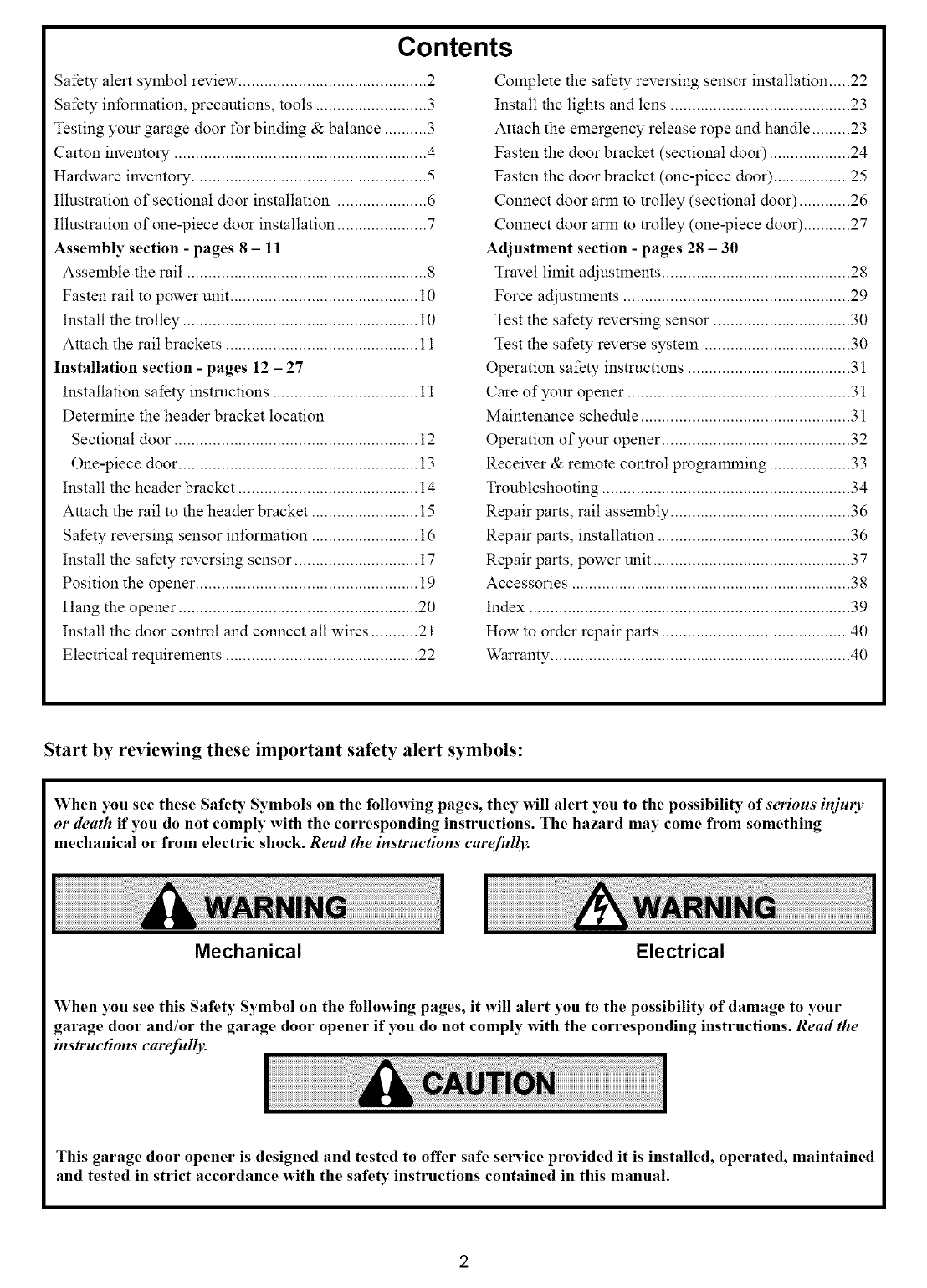
Start by reviewing these important safety alert symbols:
When you see these Safety Symbols on the following pages, they will alert you to the possibility of serious injury
or death if you do not comply with the corresponding instructions. The hazard may come from something
mechanical or from electric shock. Read the instructions carefidly.
Mechanical Electrical
When you see this Safety Symbol on the following pages, it will alert you to the possibility of damage to your
garage door and/or the garage door opener if you do not comply with the corresponding instructions. Read the
instructions carefully.
This garage door opener is designed and tested to offer safe service provided it is installed, operated, maintained
and tested in strict accordance with the safe_" instructions contained in this manual.
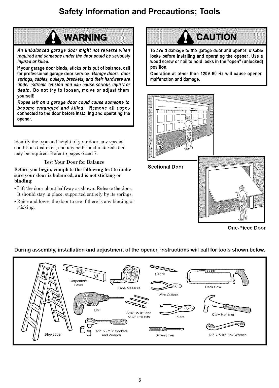
Safety Information and Precautions; Tools
An unbalancedgarage door might not re verse when
requiredand someone underthe doorcouldbe seriously
injuredorkilled.
If yourgaragedoorbinds,sticksor is out of balance,call
for professionalgaragedoorservice.Garagedoors,door
springs,cables,pulleys,brackets,and theirhardwareare
underextremetensionand can cause seriousinjury or
death. Do not try to loosen, move or adjust them
yourself!
Ropes left on a garage door could cause someone to
become entangled and killed. Remove all ropes
connectedto the doorbeforeinstallingand operatingthe
opener,
Toavoiddamageto the garagedoorandopener,disable
locksbefore installingand operatingthe opener. Use a
woodscrewornailto holdlocksinthe "open" (unlocked)
position.
Operationat other than 120V60 Hz will cause opener
malfunctionand damage.
Idemify the type and height of your door, any special
conditions that exist, and any additional materials that
may be required. Refer m pages 6 and 7.
Test Your Door for Balance
Before you begin, complete the following test to make
sure your door is balanced, and is not sticking or
binding:
• Lift the door about halfway as shown. Release the door.
It should stay in place, supported entirely by its springs.
• Raise and lower the door to see if there is any binding or
sticking.
Sectional Door
One-Piece Door
During assembly, installation and adjustment of the opener, instructions will call for tools shown below.
Stepladder
Level
Drill
Tape Measure
Penc[t
Wire Cutters
3/16", 5/16" and
5/32" Drill Bits Pliers
Screwdriver
Hack Saw
Claw Hammer
1/2" x 7/16" Box Wrench
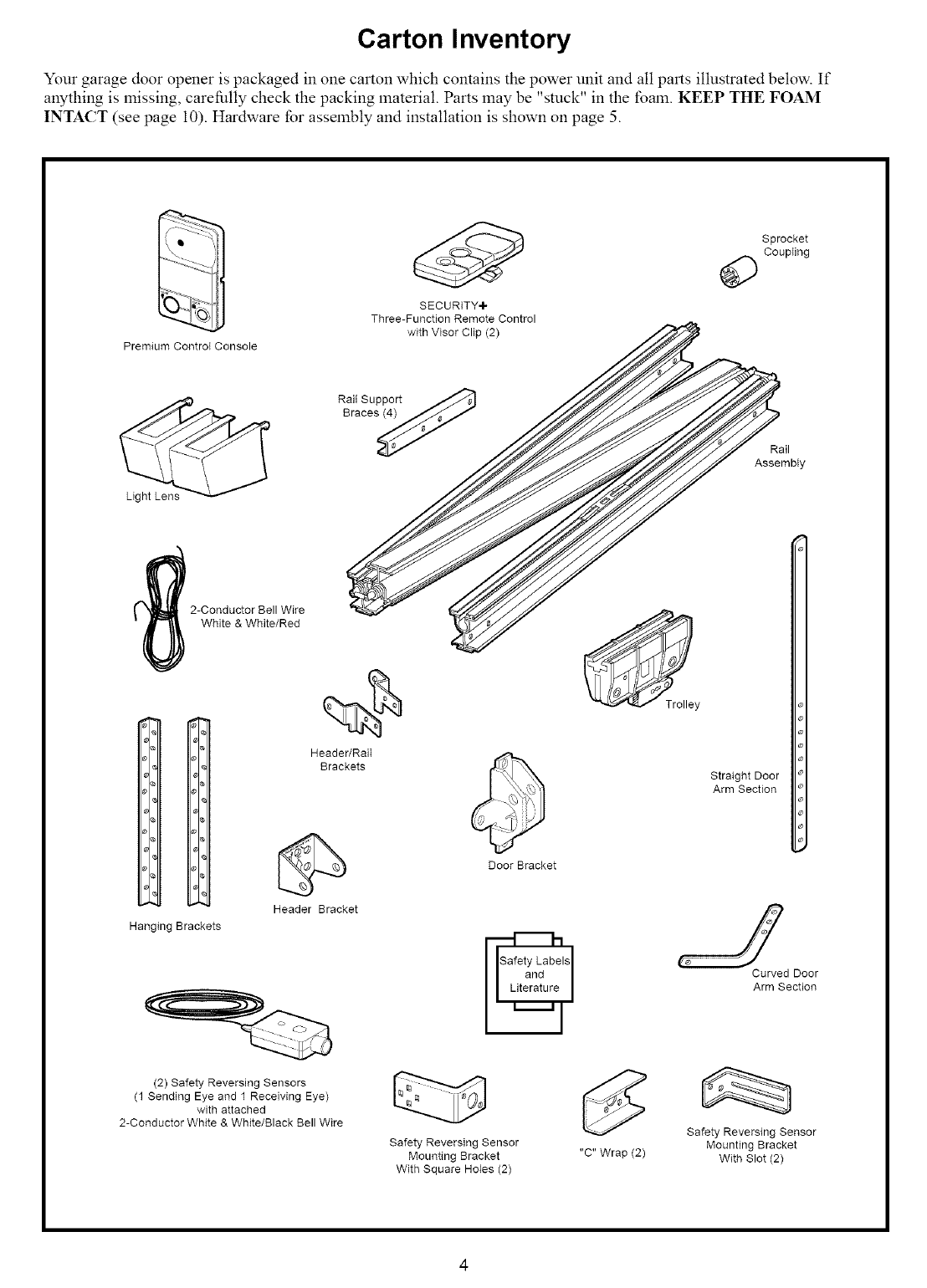
Carton Inventory
Your garage door opener is packaged in one carton which contains the power unit and all parts illustrated below. If
anything is missing, carefidly check the packing material. Parts may be "stuck" in the foaln. KEEP THE FOAM
INTACT (see page i0). Hardware for assembly and installation is shown on page 5.
_ _ Sprocket
Coupling
SECURITY+
Three-Function Remote Control
with Visor Clip (2)
Premium Control Console
Rait Support ._
araces_ Rail
Assembly
2-Conductor Bell Wire
White & White/Red
Header/RaiI
Brackets
Door Bracket
_Tto ey
Straight Door
Arm Section
Hanging Brackets
Header Bracket
Curved Door
Arm Section
(2) Safety Reversing Sensors
(1 Sending Eye and 1 Receiving Eye)
with attached
2-Conductor White & White/Black Bell Wire
Safety Reversing Sensor
Mounting Bracket
With Square Holes (2)
"C" Wrap (2)
Safety Reversing Sensor
Mounting Bracket
With Slot (2)
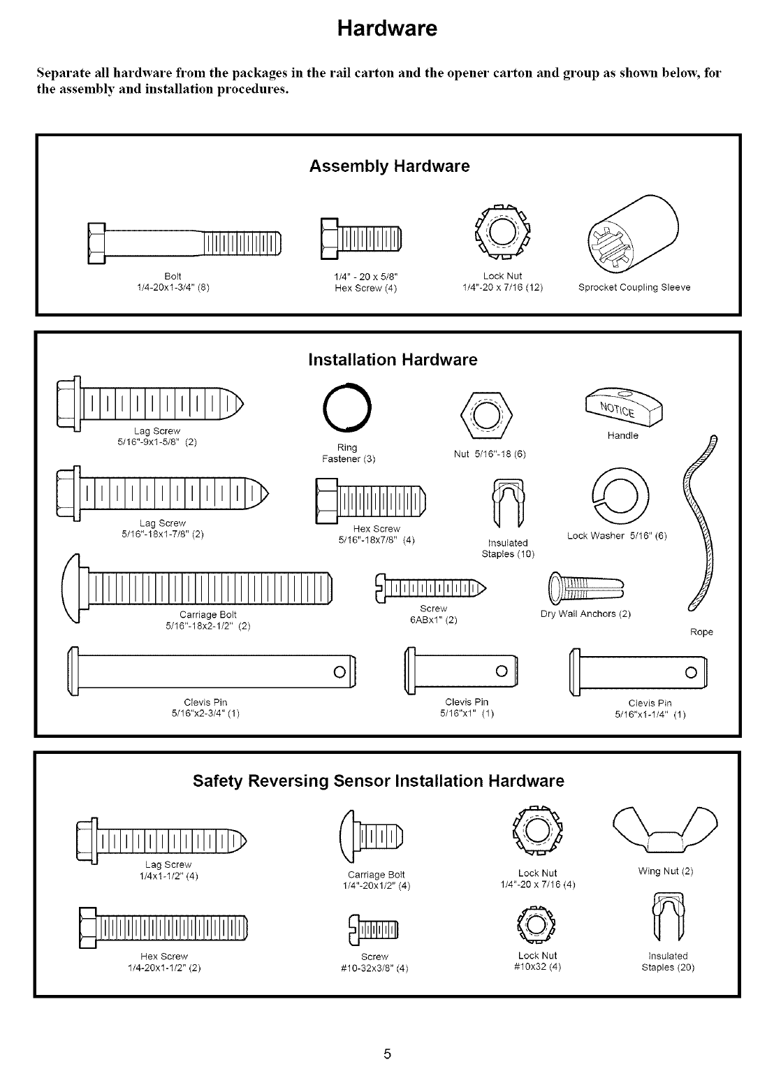
Hardware
Separate all hardware from the packages in the rail carton and the opener carton and group as shown below, for
the assembly and installation procedures.
Assembly Hardware
Bott 1/4" - 20 x 5/8" Lock Nut
1/4-20xl-3/4" (8) Hex Screw (4) 1/4"-20 x 7/16 (12) Sprocket Coupling Sleeve
1 I I I I I I I I I_
Installation Hardware
Lag Screw
5/16"-9xl-5/8" (2)
Lag Screw
5/16"-18xl -7/8" (2)
O ©
Ring Nut 5/16"-18 (6)
Fastener (3)
Hex Screw
5/16"-18x7/8" (4) Insulated
Staptes (10)
_ IIllllllllllllllllll]>
Screw
Carriage Bott 6ABxl" (2)
5/16"-18x2-1/2" (2)
o]
CIevis Pin Clevis Pin
5/16"x2-3/4" (1) 5/16"x1" (1)
Handle
©
Lock Washer 5/16" (6)
Dry Wail Anchors (2)
Rope
Clevis Pin
5/16"x1-1/4" (1)
Safety Reversing Sensor Installation Hardware
_[]1 II II II Ilalgl!IrLIwl I II II I_'_
1/4x1-1/2" (4)
©
Carriage BoIt Lock Nut Wing Nut (2)
1/4"-20x 1/2" (4) 1/4"-20 x 7/16 (4)
Screw Lock Nut insulated
:#10-32x3/8" (4) :#10x32 (4) Staples (20)
Hex Screw
1/4-20x1-1/2" (2)
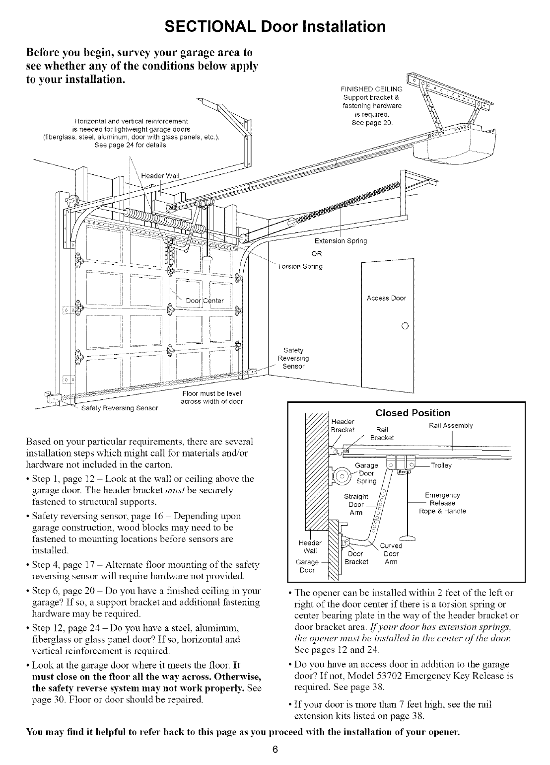
SECTIONAL Door Installation
Before you begin, survey your garage area to
see whether any of the conditions below apply
to your installation.
Horizontal and vertical reinforcement
is needed for lightweight garage doors
(fiberglass, steel, aluminum, door with glass panels, etc.).
See page 24 for details
FINISHED CEILING
Support bracket &
fastening hardware
is required
See page 20.
i \,,,Header Wall
Safety Reversing Sensor
Door
Ftoor must be level
across width of door
Based on your particular requirelnems, there are several
installation steps which might call for materials and/or
hardware not included in the carton.
• Step 1, page 12 Look at the wall or ceiling above the
garage door. The header bracket must be securely
I:astened to structural supports.
• Safety reversing sensor, page 16 Depending upon
garage construction, wood blocks may need to be
fastened to mounting locations before sensors are
installed.
• Step 4, page 17 Alternate floor m(mnting of the safety
reversing sensor will require hardware not provided.
• Step 6, page 20 Do you have a finished ceiling in your
garage? If so, a support bracket and additional thstening
hardware may be required.
• Step 12, page 24 Do you have a steel, aluminum,
fiberglass or glass panel door? If so, horizontal and
vertical reinforcelnent is required.
• Look at the garage door where it meets the floor. It
must close on the floor all the way across. Otherwise,
the safety reverse system may not work properly. See
page 30. Floor or door should be repaired.
Extension Spring
OR
Torsion Spring
Safety
Reversing
Sensor
Access Door
O
Header
Wall
Garage --
Door
Closed Position
Header Rail Assembl
Bracket Rail
o_o, _ Bracket
,,_ Garage _ Trolley
Door
Spr ng// I
Straight _i31 I Emergency
Door _,,)y _oR212aHSae die
• The opener can be installed within 2 feet of the left or
right of the door center if there is a torsion spring or
center bearing plate in the way of the header bracket or
door bracket area. If),our door has extension strings;
the opener must be installed in the center of the door.
See pages 12 and 24.
• Do you have an access door in addition to the garage
door? If not, Model 53702 Emergency Key Release is
required. See page 38.
• If your door is more than 7 feet high, see the rail
extension kits listed on page 38.
You may find it helpful to refer back to this page as you proceed with the installation of your opener.
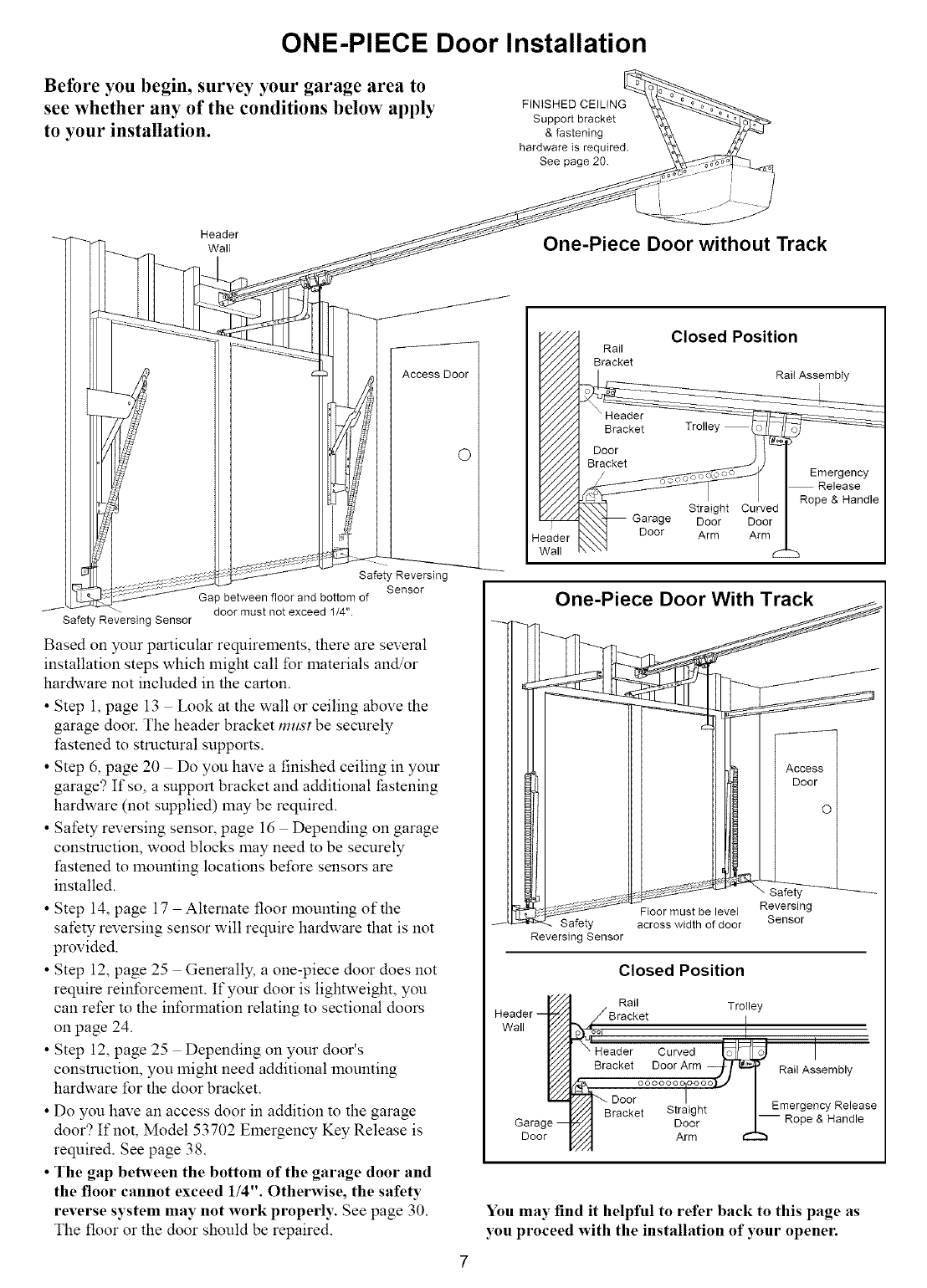
ONE-PIECE Door Installation
Before you begin, survey your garage area to
see whether any of the conditions below apply
to your installation.
FINISHED CEILING
Support bracket
& fastening
hardware is required.
See page 20.
Header
Wall One-Piece Door without Track
Access Door
O
Safety Reversing
Sensor
Gap between floor and bottom of
door must not exceed 1/4".
Safety Reversing Sensor
Based on your particular requirelnents, there are several
installation steps which might call for materials and/or
hardware not included in the carton.
• Step 1, page 13 Look at the wall or ceiling above the
garage door. The header bracket mzlst be secnrely
l:astened to structnral supports.
• Step 6, page 20 Do you have a finished ceiling in your
garage? If so, a snpport bracket and additional lhstening
hardware (not supplied) may be required.
• Safety reversing sensor, page 16 Depending on garage
construction, wood blocks may need to be secnrely
fastened to mounting locations before sensors are
installed.
• Step 14, page 17 Alternate floor lnounting of the
safety reversing sensor will require hardware that is not
provided.
• Step 12, page 25 Generally, a one-piece door does not
require reinforcelnent. If your door is lightweight, you
can refer to the information relating to sectional doors
on page 24.
• Step 12, page 25 Depending on your door's
construction, you might need additional lnounting
hardware for the door bracket.
• Do you have an access door in addition to the garage
door? If not, Model 53702 Emergency Key Release is
required. See page 38.
• The gap between the bottom of the garage door and
the floor cannot exceed 1/4". Otherwise, the safety
reverse system may not work properly. See page 30.
The floor or the door should be repaired.
Rail
Bracket
Header
Bracket
Door
Bracket
Closed Position
Rail Assembly
Trolley
Straight Curved
Garage Door Door
Door Arm Arm
Emergency
Release
Rope & Handle
One-Piece Door With Track
Floor must be level
Safety across width of door
Reversing Sensor
Access I
Door I
ol
• ;afeb
Reversing
Sensor
Header E
Wall
Garage--
Door
Closed Position
/Rail Trolley
_ Bracket I
r_l Header Curved _ I
Bracket Door Arm Ra, Assembly
f//zl " Door _. '.._/Emergency Release
"///A Bracket otralgm I_
/_///] Door 1-- Rope & Handle
Arm
You may find it helpful to refer back to this page as
you proceed with the installation of your opener.
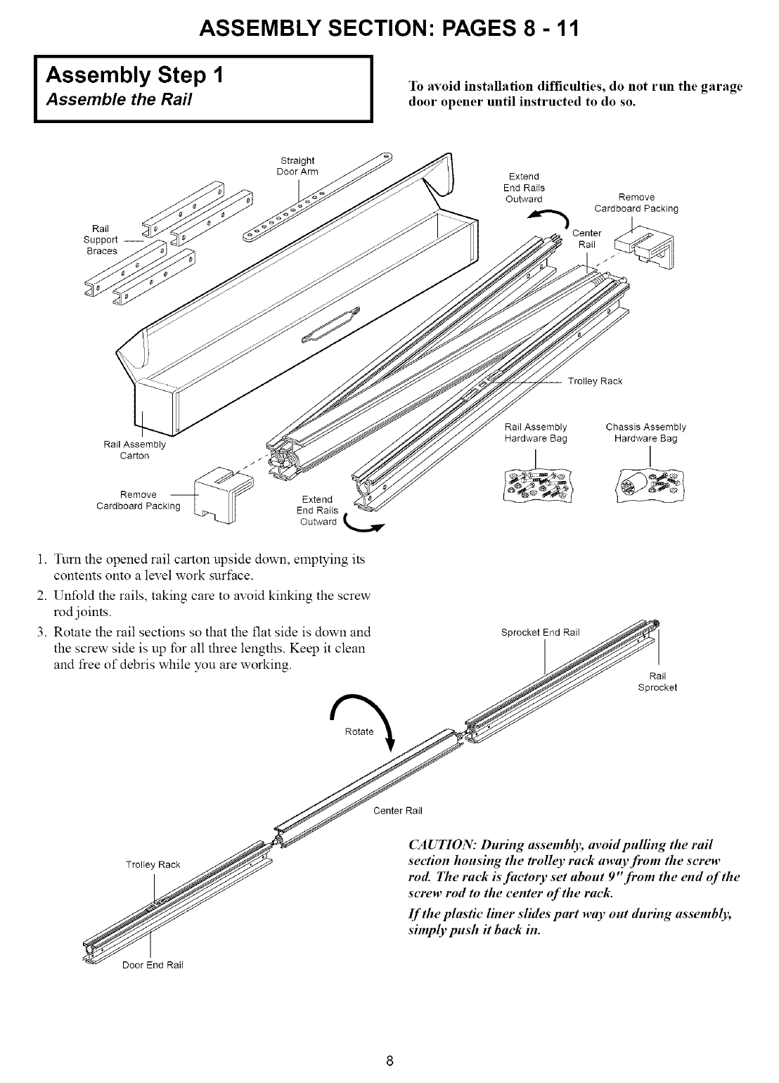
IASSEMBLY SECTION: PAGES 8 - 11
Assembly Step 1
Assemble the Rail ITo avoid installation difficulties, do not run the garage
door opener until instructed to do so.
Rail
Support --
Braces
Straight
DoorArm Extend
End RaiIs
Outward Remove
Cardboard Packing
Center
Rail
Trolley Rack
Rail Assembly
Carton / / _
Remove
Cardboard Packing Extend
End Raits
Outward
1. Turn the opened rail carton upside down, emptying its
contents onto a level work snrt:ace.
2. Unfold the rails, taking care to avoid kinking the screw
rod joints.
3. Rotate the rail sections so that the flat side is down and
the screw side is up for all three lengths. Keep it clean
and free of debris while you are working.
Rail Assembly
Hardware Bag
Sprocket End Rail
Chassis Assembly
Hardware Bag
I
Rail
Sprocket
Rotate
Trolley Rack
Door End Rail
Center Rail
CAUTION: During assemblk; avoid pulling the rail
section housing the trolley rack away from the sere,,
rod. The rack is factory set about 9"from the end of the
screw rod to the center of the rack.
If the plastic liner slides part way out during assembly,
simply push it back in.
Assembly Step 1 (Continued)
Assemble the Rail
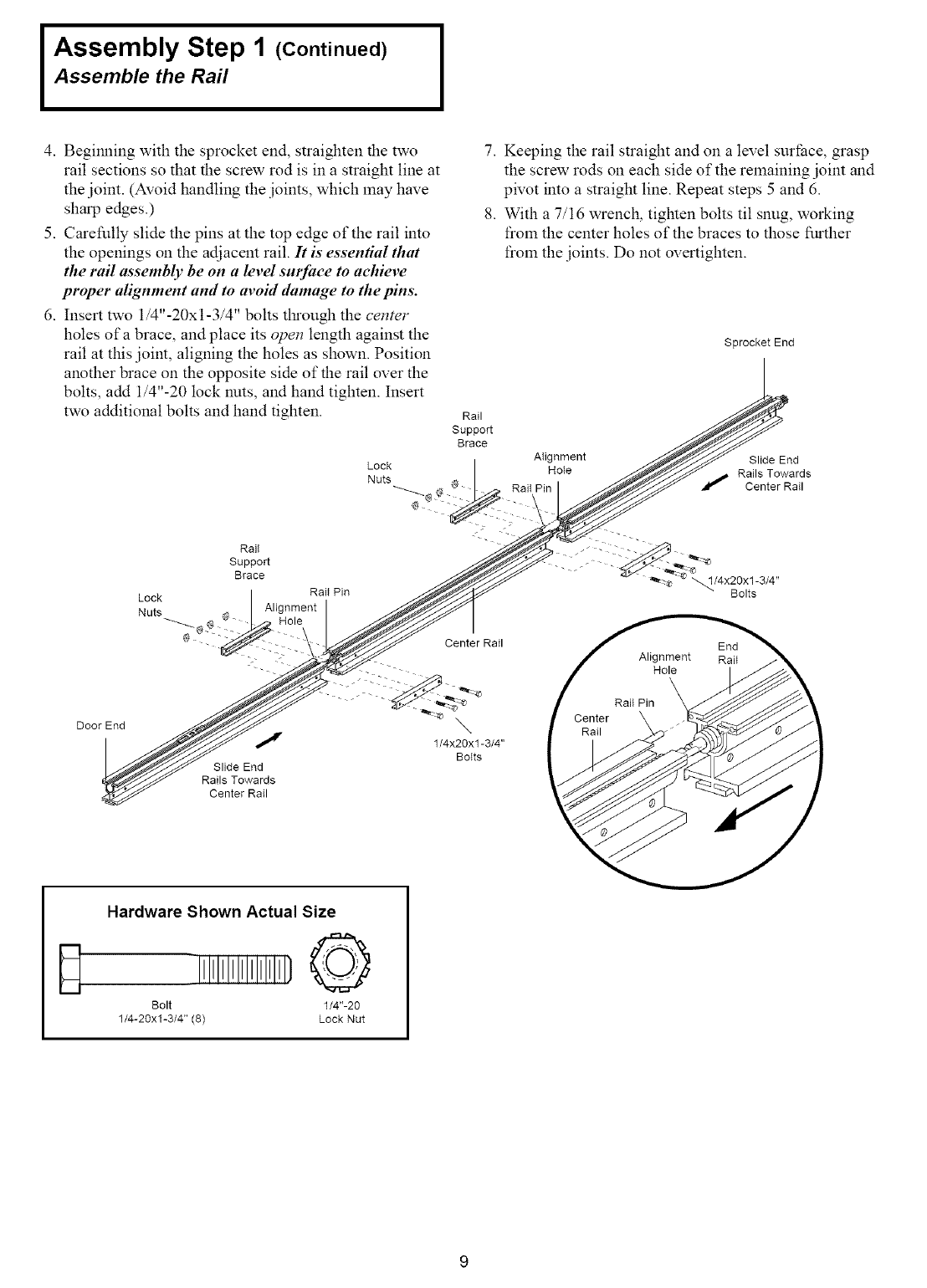
4. Begim_ing with the sprocket end, straighten the two
rail sections so that the screw rod is in a straight line at
the joint. (Avoid handling the joints, which may have
sharp edges.)
5. Carefully slide the pins at the top edge of the rail into
the openings on the adjacent rail. It is essential that
the rail assembly be on a level surface to achieve
proper alignment and to avoM damage to the pins.
6. Insert two 1/4"-20xl-3/4" bolts tl_ough the center
holes of a brace, and place its open length against the
rail at this joint, aligning the holes as shown. Position
another brace on the opposite side of the rail over the
bolts, add 1/4"-20 lock nuts, and hand tighten. Insert
two additional bolts and hand tighten.
7. Keeping the rail straight and on a level surface, grasp
the screw rods on each side of the remaining joint and
pivot into a straight line. Repeat steps 5 and 6.
8. With a 7/16 wrench, tighten bolts til snug, working
from the center holes of the braces to those further
from the joints. Do not overtighten.
Sprocket End
Rail
Support
Brace
AIignment Slide End
Lock Hote Rails Towards
Nuts Center Rail
Door End
D
Lock
Nuts
Center Rail
1/4x20x1-3/4"
Bolts
Slide End
Rails Towards
Center Rail
Hardware Shown Actual Size
Bolt 1/4"-20
1/4-20xl-3/4" (8) Lock Nut
Assembly Step 2
Fasten the Rail To the Power Unit
and Install the Trolley
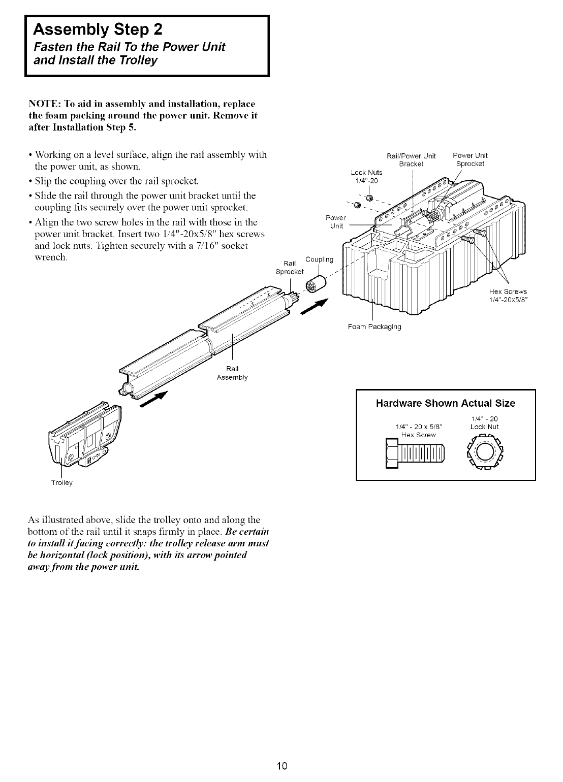
NOTE: To aid in assembly and installation, replace
the foam packing around the power unit. Remove it
after Installation Step 5.
• Working on a level surface, align the rail assembly with
the power unit, as shown.
• Slip the coupling over the rail sprocket.
• Slide the rail through the power unit bracket until the
coupling fits securely over the power unit sprocket.
• Align the two screw holes in the rail with those in the
power unit bracket. Insert two 1/4"-20x5/8" hex screws
and lock nuts. Tighten securely with a 7/16" socket
wrench.
Rail/Power Unit
Bracket
Lock Nuts
1/4"-20
I
Power
Unit --
Rail Coupling
Spr°cket/_
7
Foam Packaging
Power Unit
Sprocket
Hex Screws
1/4"-20x5/8"
TroIley
Rail
Assembly
Hardware Shown Actual Size
1/4" - 20
1/4" - 20 x 5/8" Lock Nut
As illustrated above, slide the trolley omo and along the
bottom of the rail until it snaps firmly in place. Be certain
to install #facing correctly: the trolley release arm must
be horizontal (lock position), with its" arrow pointed
away from the power unit.
10
Assembly Step 3
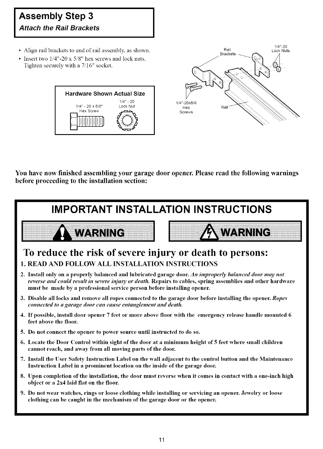
Attach the Rail Brackets
• Align rail brackets to end of rail assembly, as shown.
• Insert two i/4"-20 x 5/8" hex screws and lock nuts.
Tighten securely with a 7/16" socket.
Rail 1/4"-20
Lock Nuts
Hardware Shown Actual Size
1/4" - 20
1/4" -20 x 5/8" Lock Nut 1/4"-20x5/8
Hex
Screws
You have now finished assembling your garage door opener. Please read the following warnings
before proceeding to the installation section:
IMPORTANT INSTALLATION INSTRUCTIONS
To reduce the risk of severe injury or death to persons:
1. READ AND FOLLOW ALL INSTALLATION INSTRUCTIONS
2. Install only on a properly balanced and lubricated garage door. An improperly balanced door may not
reverse and could result in severe injury or death. Repairs to cables, spring assemblies and other hardware
must be made by a professional service person before installing opener.
3. Disable all locks and remove all ropes connected to the garage door before installing the openen Ropes
connected to a garage door can cause entanglement and death.
4. If possible, install door opener 7 feet or more above floor with the emergency release handle mounted 6
feet above the floor.
5. Do not connect the opener to power source until instructed to do so.
6. Locate the Door Control within sight of the door at a minimum height of 5 feet where small children
cannot reach, and away from all moving parts of the dool:
7. Install the User Safety Instruction Label on the wall adjacent to the control button and the Maintenance
Instruction Label in a prominent location on the inside of the garage door.
8. Upon completion of the installation, the door must reverse when it comes in contact with a one-inch high
object or a 2x4 laid flat on the floor.
9. Do not wear watches, rings or loose clothing while installing or servicing an openen Jewelry or loose
clothing can be caught in the mechanism of the garage door or the openel:
11
INSTALLATION SECTION: PAGES 12- 27
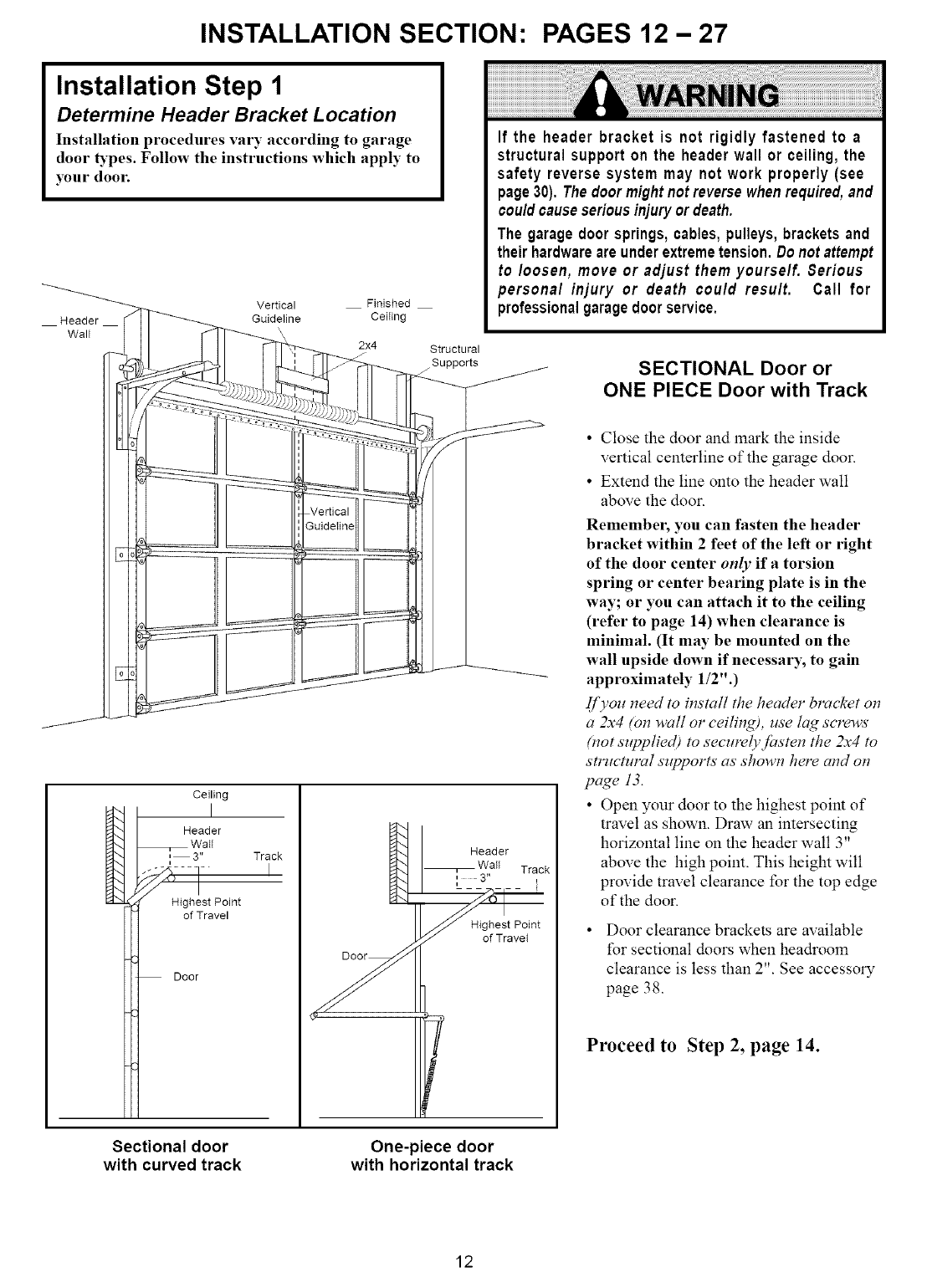
Installation Step 1
Determine Header Bracket Location
Installation procedures vary according to garage
door _'pes. Follow the instructions which apply to
your door.
Header
Wall
Vertical Finished
GuideIine Ceiting
2x4 Structural
Supports
If the header bracket is not rigidly fastened to a
structural support on the header wall or ceiling, the
safety reverse system may not work properly (see
page30). The doormightnotreversewhenrequired,and
cou/dcauseseriousinjuryordeath.
The garagedoorsprings,cables,pulleys,bracketsand
their hardwareareunderextremetension.Donotattempt
to/oosen, move or adjust them yourse/f. Serious
persona/ injury or death cou/d resu/t. Call for
professionalgaragedoorservice.
SECTIONAL Door or
ONE PIECE Door with Track
Ceiling
Header
Wail
, 3" Track
i
...... !- I
_High st Point
of Travel
Door
Header
Wall Track
i 3"
i [
Highest Point
of Travet
• Close the door and mark the inside
vertical centerline of the garage door.
• Extend the line onto the header wall
above the door.
Remember, you can fasten the header
bracket within 2 feet of the left or right
of the door center only if a torsion
spring or center bearing plate is in the
way; or you can attach it to the ceiling
(refer to page 14) when clearance is
minimal. (It may be mounted on the
wall upside down if necessary; to gain
approximately 1/2".)
Ij)'ou need to install the header bracket otl
a 2x4 (on wall or ceiling), use lag screws
(not supplied) to securelyJasten the 2x4 to
structural supports as shown here and on
page 13.
• Open your door to the highest point of
travel as shown. Draw an intersecting
horizontal line on the header wall 3"
above the high point. This height will
provide travel clearance for the top edge
of the door.
Door clearance brackets are available
for sectional doors when headroom
clearance is less than 2". See accessory
page 38.
Proceed to Step 2, page 14.
Sectional door
with curved track One-piece door
with horizontal track
12
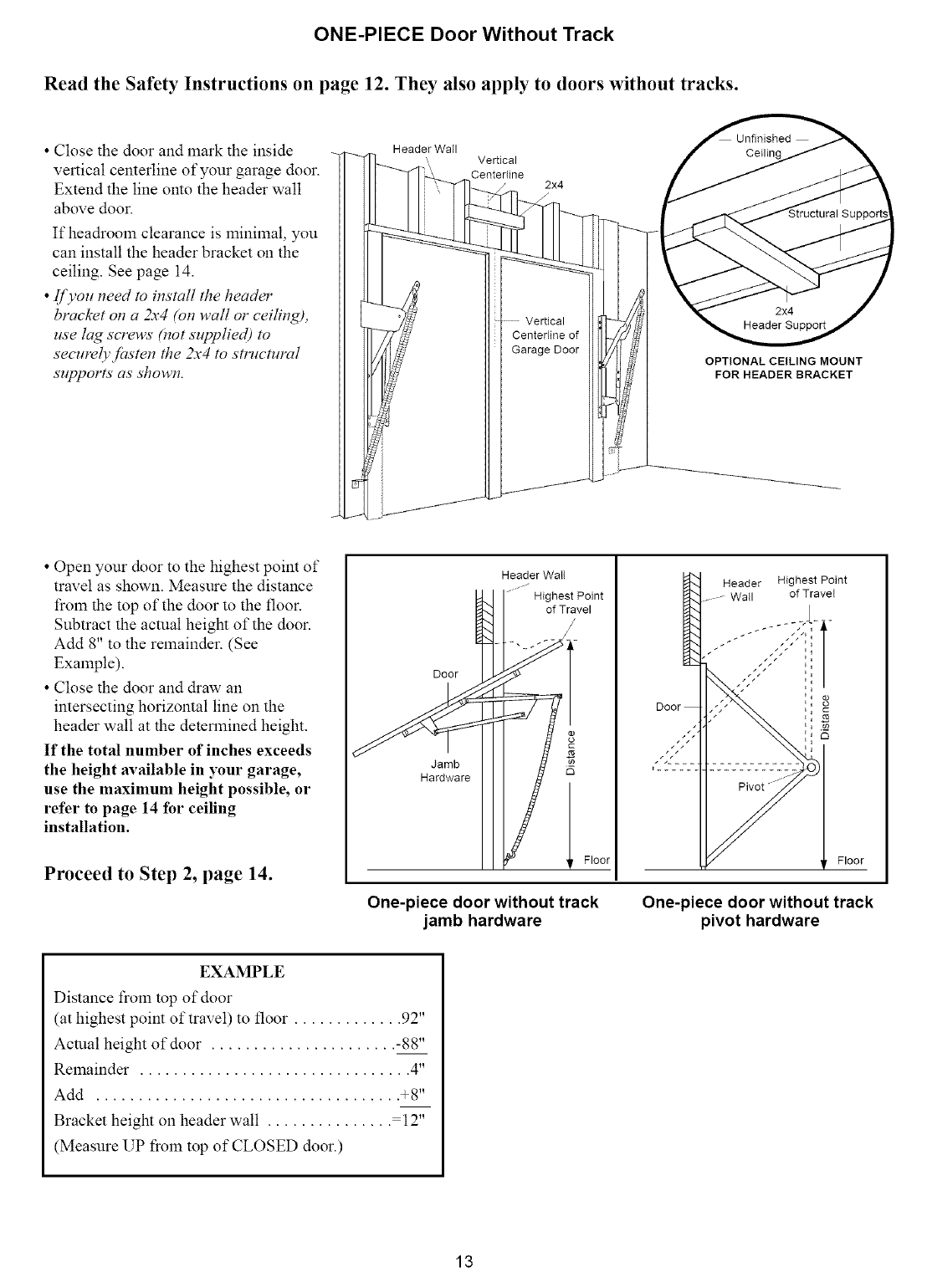
ONE-PIECE Door Without Track
Read the Safety Instructions on page 12. They also apply to doors without tracks.
•Close the door and mark the inside
vertical centerline of your garage door.
Extend the line onto the header wall
above door.
If headrooln clearance is minimal, you
can install the header bracket on the
ceiling. See page 14.
•IJ)'ou need to install the header
bracket on a 2x4 (on wall or ceiling),
use lag screws (not supplied) to
securelyJasten the 2x4 to smlcmral
supports as shown.
Header Wail Vertical
Centerline 2x4
OPTIONAL CEILING MOUNT
FOR HEADER BRACKET
• Open your door to the highest point of
travel as shown. Measure the distance
from the top of the door to the floor.
Subtract the actual height of the door.
Add 8" to the remainder. (See
Example).
• Close the door and draw an
intersecting horizontal line on the
header wall at the determined height.
If the total number of inches exceeds
the height available in your garage,
use the maximum height possible, or
refer to page 14 for ceiling
installation.
Proceed to Step 2, page 14.
Door 1
Jamb
Hardware
Header Wail
.... J
Highest Point
of Travel
/
/
i Floor
Header Highest Point
Wail of TraveI
One-piece door without track
jamb hardware One-piece door without track
pivot hardware
EXAMPLE
Distance frolTl top of door
(at highest point of travel) to floor ............. 92"
Actual height of door ...................... -88"
Remainder ................................ 4"
Add .................................... +8"
Bracket height on header wall ............... 12"
(Measure UP froln top of CLOSED door.)
13
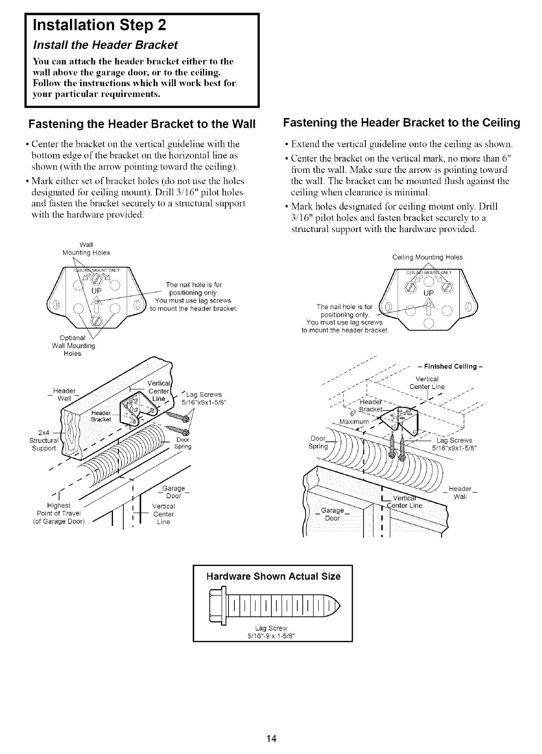
Installation Step 2
Install the Header Bracket
You can attach the header bracket either to the
wall above the garage door, or to the ceiling.
Follow the instructions which will work best for
your particular requirements.
Fastening the Header Bracket to the Wall
• Center the bracket on the vertical guideline with the
bottom edge of the bracket on the horizontal line as
shown (with the arrow pointing toward the ceiling).
• Mark either set of bracket holes (do not use the holes
designated for ceiling mount). Drill 3/16" pilot holes
and thsten the bracket securely to a structural support
with the hardware provided.
Wall
Mounting HoIes
Fastening the Header Bracket to the Ceiling
• Extend the vertical guideline onto the ceiling as shown.
• Center the bracket on the vertical mark, no lnore than 6"
froln the wall. Make sure the arrow is pointing toward
the wall. The bracket can be mounted flush against the
ceiling when clearance is minimal.
• Mark holes designated for ceiling mount only. Drill
3/16" pilot holes and thsten bracket securely to a
strncmral support with the hardware provided.
Ceiling Mounting Holes
Optional
Wall Mounting
Holes
The nail hole is for
positioning only
You must use lag screws
to mount the header bracket
_Header "Lag Screws
Wall 5/16"x9x1-5/8"
2x4
Structural Door
Support Spring
The nail hole is for
positioning only
You must use lag screws e_=
to mount the header bracket.
/
/
/
/ Garage
I -- --
Door
Highest Vertical
Point of Travel Center
(of Garage Door) Line
Header_
Wall
Hardware Shown Actual Size
lllllllll)
Lag Screw
5/16"-9 x 1-5/8"
14
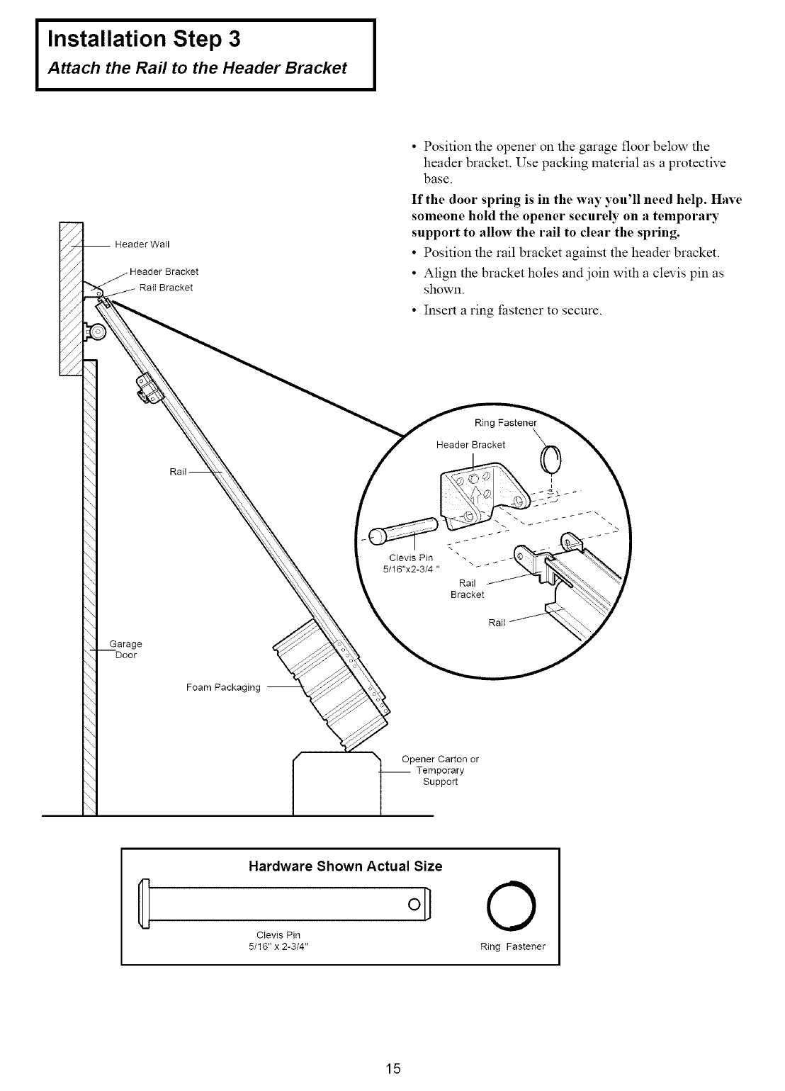
Installation Step 3
Attach the Rail to the Header Bracket
Header Wall
• Position the opener on the garage floor below the
header bracket. Use packing material as a protective
base.
If the door spring is in the way you'll need help. Have
someone hold the opener securely on a temporary
support to allow the rail to clear the spring.
•Position the rail bracket against the header bracket.
• Align the bracket holes and join with a clevis pin as
shown.
• Insert a ring fastener to secure.
Garage
Door
Foam Packaging --
Ring Fastener
Header Bracket 0
i
_J
Clevis Pin _ -.
5/16"x2-3/4 "
Rail
Bracket
Rail
/1 Opener Carton or
-- Temporary
Support
Hardware Shown Actual Size
o]
Clevis Pin
5/16" x 2-3/4"
O
Ring Fastener
15
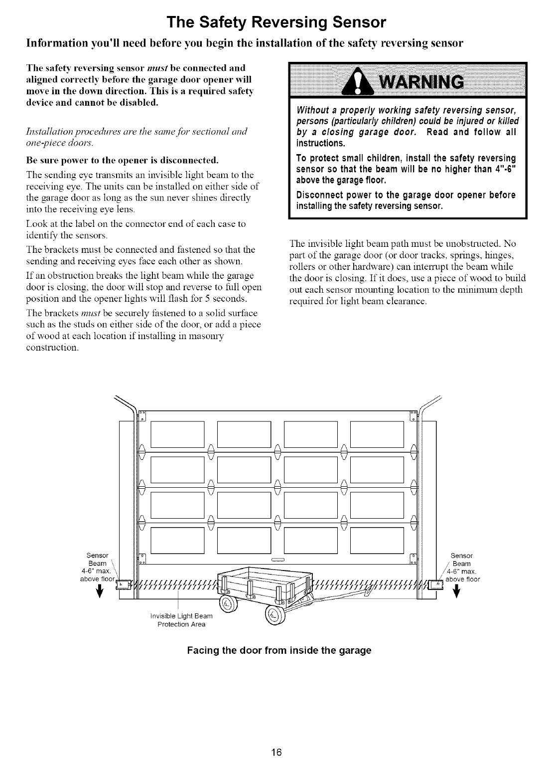
The Safety Reversing Sensor
Information you'll need before you begin the installation of the safety reversing sensor
The safety reversing sensor must be connected and
aligned correctly before the garage door opener will
move in the down direction. This is a required safety
device and cannot be disabled.
Installation procedures are the same Jbr sectional and
one-piece dool_=
Be sure power to the opener is disconnected.
The sending eye transmits an invisible light beam to the
receiving eye. The units can be installed on either side of
the garage door as long as the sun never shines directly
into the receiving eye lens.
Look at the label on the connector end of each case to
identify the sensors.
The brackets lnUStbe connected and thstened so that the
sending and receiving eyes t:ace each other as shown.
If an obstruction breaks the light beam while the garage
door is closing, the door will stop and reverse to fidl open
position and the opener lights will flash for 5 secon&.
The brackets must be securely _hstened to a solid surthce
such as the studs on either side of the door, or add a piece
of wood at each location if installing in masonry
constrnction.
Without aproperly working safety reversing sensor,
persons (particularlychildren)couldbe injuredor killed
by a closing garage door. Read and follow all
instructions,
To protect small children, install the safety reversing
sensor so that the beam will be no higher than 4"-6"
abovethegaragefloor.
Disconnect power to the garage door opener before
installingthesafetyreversingsensor.
The invisible light beam path lnnst be unobstrncted. No
part of the garage door (or door tracks, springs, hinges,
rollers or other hardware) can intemtpt the beam while
the door is closing. If it does, use a piece of wood to bnild
out each sensor mounting location to the minimum depth
required for light beam clearance.
+ J+ + 111
+ J+ + 1111
Facing the door from inside the garage
16
Installation Step 4
Install the Safety Reversing Sensor
(Receiving and Sending Eyes)
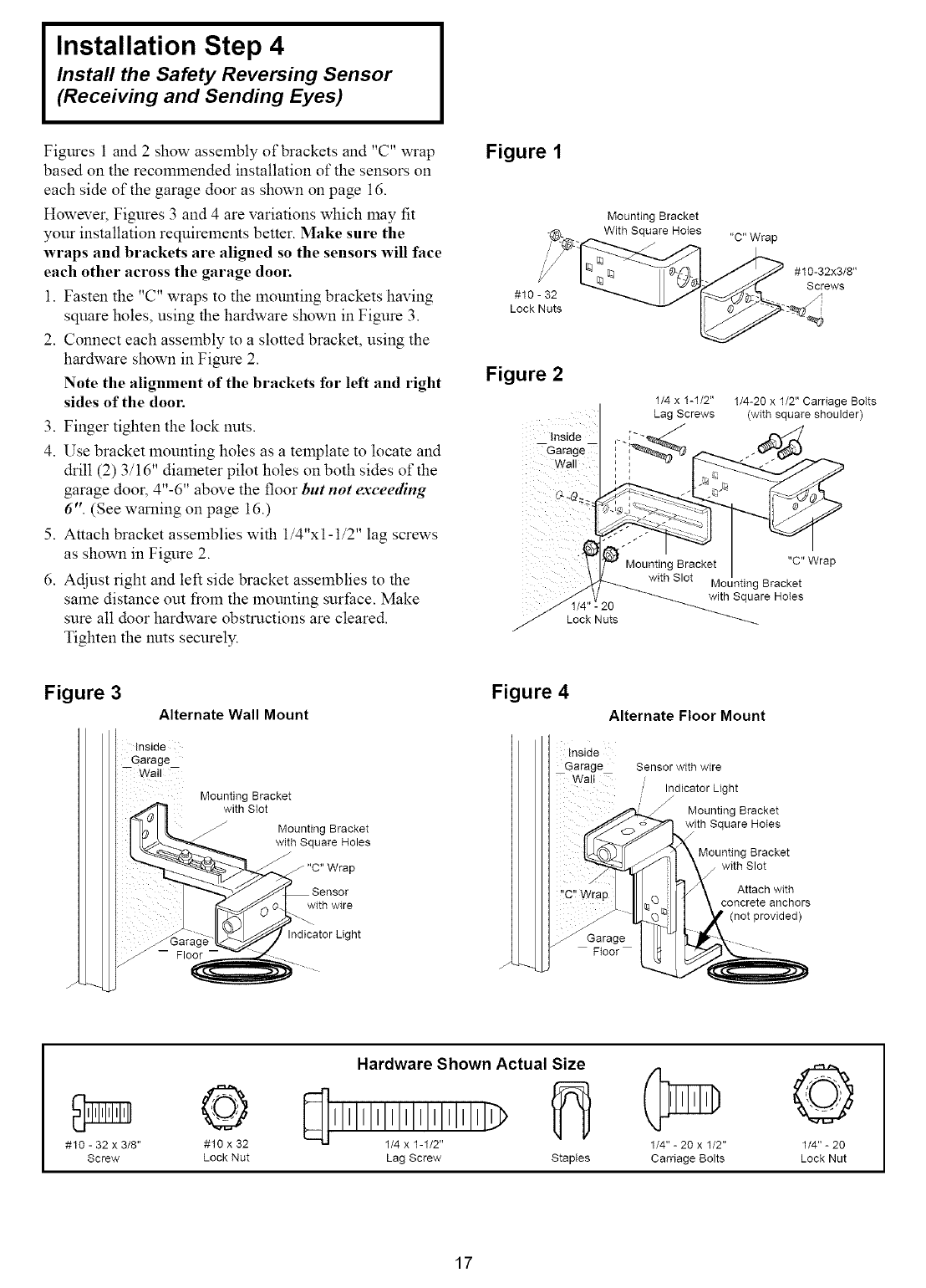
Figures 1 and 2 show assembly of brackets and "C" wrap
based on the recolmnended installation of the sensors on
each side of the garage door as shown on page 16.
However, Figures 3 and 4 are variations which may fit
your installation requirelnents better. Make sure the
wraps and brackets are aligned so the sensors will face
each other across the garage door.
1. Fasten the "C" wraps to the mounting brackets having
sqtmre holes, using the hardware shown in Figure 3.
2. Connect each assembly to a slotted bracket, using the
hardware shown in Figure 2.
Note the alignment of the brackets for left and right
sides of the door.
3. Finger tighten the loci( nuts.
4. Use bracket mounting holes as a template to locate and
drill (2) 3/16" diameter pilot holes on both sides of the
garage door, 4"-6" above the floor but not exceeding
6". (See warning on page 16.)
5. Attach bracket assemblies with 1/4"x1-1/2" lag screws
as shown in Figure 2.
6. Adjust right and left side bracket assemblies to the
same distance out froln the mounting snrface. Make
sure all door hardware obstrnctions are cleared.
Tighten the nuts securely.
Figure 1
#10 - 32
Lock Nuts
Mounting Bracket
With Square Holes "C" Wrap
#10-32x3/8"
Screws
Figure 2
Inside
--Garage--
Wall , ,
1/4 x 1-1/2"
Lag Screws
1/4-20 x 1/2" Carriage Bolts
(with square shoulder)
20
Lock Nuts
"C" Wrap
Mounting Bracket
with Square HoIes
Figure 3
Alternate Wall Mount
Inside
Garage
Wail
Mounting Bracket
with SIot
/_ Mounting Bracket
with Square Holes
Figure 4
Alternate Floor Mount
Inside
Garage
-- Wall _
Garage
Floor
Sensor with wire
Indicator Light
Mounting Bracket
with Square Holes
Mounting Bracket
j with Slot
Attach with
concrete anchors
(not provided)
#10 - 32 x 3/8"
Screw
©
#10 x 32
Lock Nut
Hardware Shown Actual Size
_[] I I I I I I I Ill/! IXlll_ll/12 I I I I I l)
Lag Screw Staples
1/4" - 20 x 1/2"
Carriage Bolts
©
1/4" - 20
Lock Nut
17
I Installation Step 4 (Continued) I
Install the Safety Reversing Sensor
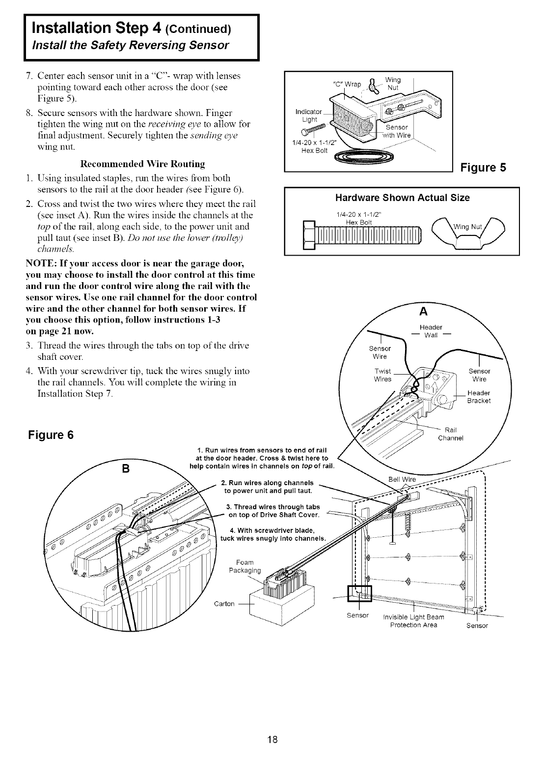
7. Center each sensor unit in a "C"- wrap with lenses
pointing toward each other across the door (see
Figure 5).
8. Secure sensors with the hardware shown. Finger
tighten the wing nut on the receiving eye to allow for
final adjustment. Securely tighten the sending eye
wing nut.
Recommended Wire Routing
1. Using insulated staples, run the wires froln both
sensors m the rail at the door header (see Figure 6).
2. Cross and twist the two wires where they meet the rail
(see inset A). Run the wires inside the channels at the
top of the rail, along each side, m the power unit and
pull taut (see inset B). Do not use the lower (tmllc3')
channels.
NOTE: If your access door is near the garage dool;
you may choose to install the door control at this time
and run the door control wire along the rail with the
sensor wires. Use one rail channel for the door control
wire and the other channel for both sensor wires. If
you choose this option, follow instructions 1-3
on page 21 now.
3. Tlu'ead the wires through the tabs on top of the drive
shaft cover.
4. With your screwdriver tip, rock the wires snugly into
the rail channels. You will complete the wiring in
Installation Step 7.
Figure 5
Hardware Shown Actual Size
1/4-20 x 1-1/2"
Hex Bolt
Sensor
Wire
Twist
Wires
Sensor
Wire
Header
Bracket
Figure 6
B
I, Run wires from sensors to end of rail
at the door header. Cross & twist here to
help contain wires in channels on tot
2, Run wires along channels
to power unit and pull taut,
3, Thread wires through tabs
on top of Drive Shaft Cover.
tuck wires snugly into channels.
Bell Wire
Rail
Channel
Foam
Packaging
Carton
Sensor Invisible Light Beam
Protection Area Sensor
18
Installation Step 5
Position the Opener
Follow instructions which apply to your door type
as illustrated.
SECTIONAL Door or ONE-PIECE Door with Track
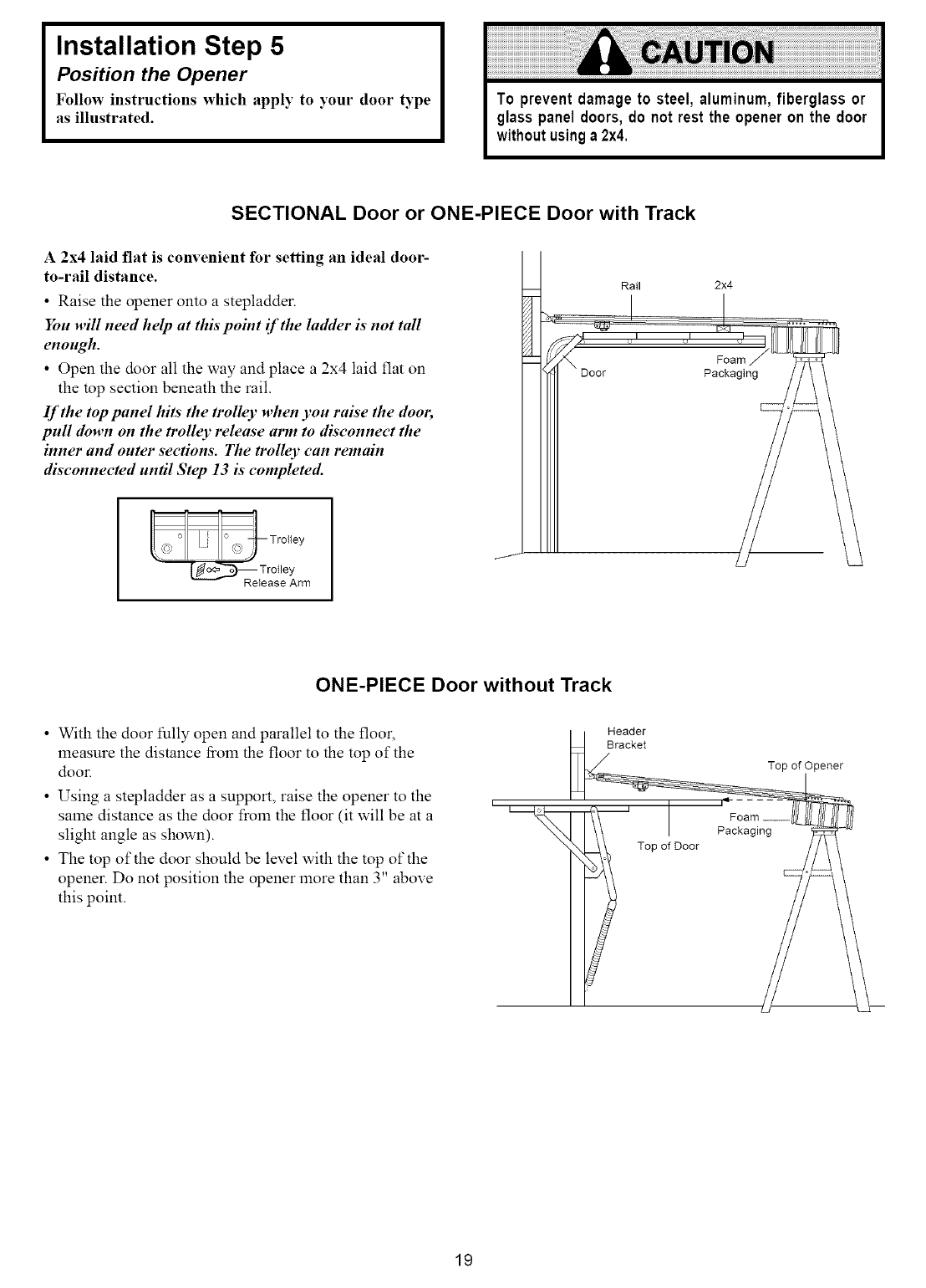
A2x4 laid flat is convenient for setting an ideal door-
to-rail distance.
•Raise the opener onto a stepladder
You will need help at this point if the ladder is not tall
enough.
• Open the door all the way and place a 2x4 laid flat on
the top section beneath the rail.
If the top panel hits the trolley when you raise the door,
pull down on the trolley release arm to disconnect the
inner and outer sections. The trolley can remain
disconnected until Step 13 is completed.
Rail 2x4
Foam
Packaging
_Trotley ReIease Arm
ONE-PIECE Door without Track
• With the door fully open and parallel to the floor,
lneasure the distance from the floor to the top of the
door.
• Using a stepladder as a support, raise the opener to the
same distance as the door froln the floor (it will be at a
slight angle as shown).
• The top of the door should be level with the top of the
opener. Do not position the opener more than 3" above
this point.
Header
Bracket
Top of Door
Top of Opener
Packaging
19
I Installation Step 6
Hang the Opener I
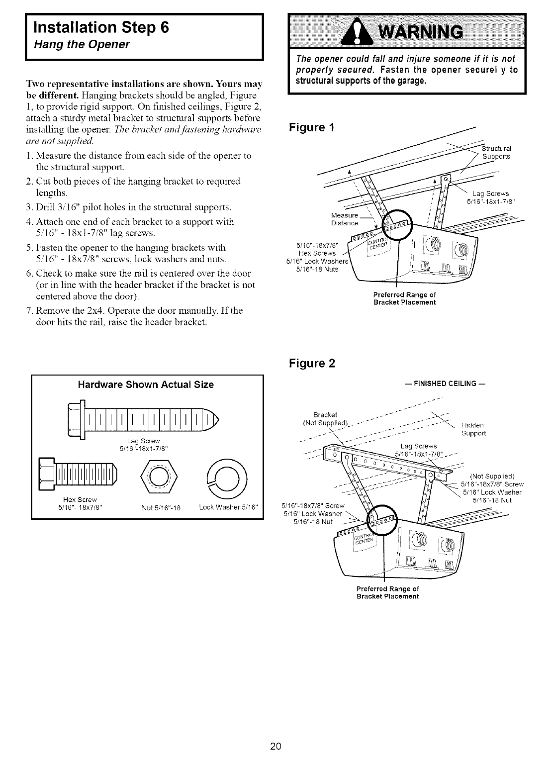
Two representative installations are shown. Yours may
be different. Hanging brackets should be angled, Figure
1, to provide rigid snpport. On finished ceilings, Figure 2,
attach a stnrdy metal bracket to strnctural supports before
installing the opener. The bracket and fbstening hardware
are not supplied.
1. Measure the distance from each side of the opener to
the structnral support.
2. Cut both pieces of the hanging bracket to required
lengths.
3. Drill 3/16" pilot holes in the structnral supports.
4. Attach one end of each bracket to a support with
5/16" - 18xt-7/8" lag screws.
5. Fasten the opener to the hanging brackets with
5/16" - 18x7/8" screws, lock washers and nuts.
6. Check to lnake sure the rail is centered over the door
(or in line with the header bracket if the bracket is not
centered above the door).
7. Relnove the 2x4. Operate the door lnanually. If the
door hits the rail, raise the header bracket.
Figure 1
Measure
Distance
5/16"-18x7/8"
Hex Screws
5/16" Lock Washers
5/16"- 18 Nuts
Preferred Range of
Bracket Placement
Supports
Lag Screws
5/16"-18xl-7/8"
Hardware Shown Actual Size
Lag Screw
5/16"-18xl-7/8"
Hex Screw
5/16"- 18x7/8" Nut 5/16"-18 Lock Washer 5/16"
Figure 2
-- FINISHED CEILING --
5/16"-18 Nut
Preferred Range of
Bracket Placement
2O
Installation Step 7
Install the Premium Control Console
and Connect all Wiring
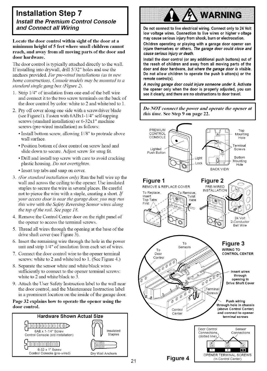
Locate the door control within sight of the door at a
minimum height of 5feet where small children cannot
reach, and away from all mo,ing parts of the door and
door hardware.
The door control is typically attached directly to the wall.
If installing imo dxywall, drill 5/32" holes and use the
anchors wovided. For plv-wired installations' (as'in new
home consm¢ction), Console models' may be mounted to a
standard single gang box (Figure 2).
1. Strip 1/4" of insulation from one end of the bell wire
mad comaect it to the two screw terlninals on the back of
the door control by color: white to 2 and white/red to 1.
2. Pry off cover along one side with a screwdriver blade
(see Figurel). Fasten with 6ABxl-1/4" self-tapping
screws (standard installation) or 6-32x t" machine
screws (we-wired installation) as follows:
• Install bottoln screw, allowing 1//8" to protrude above
wall surface.
• Position bottom of door control on screw head and
slide down to secure. Adjust screw for snug fit.
• Drill and install top screw with care to avoid cracking
plastic housing. Do not overtighten.
• Insert top tabs and snap on cover.
3. (For standard installation only) Run the bell wire up the
wall and across the ceiling to the opener. Use insulated
staples to secure the wire in several places. Be careful
not to pierce the wire with a staple, creating a short. If
),our access door is'near the garage doot; you may lwn
th# wire with the Safe O,Reversing ,Sensor wires along
the top of the rail. Seepage 18.
4. Relnove the Control Center door on the right panel of
the opener to access the terlninal screws.
5. Thread all wires tlmmgh the opening at the base of the
drive shaft cover (see Figure 3).
6. Insert the relnaining wire tl_ough the hole in the power
unit and strip 1/4" of insulation froln each set of wires.
7. Connect the door comrol wire to the opener terlninal
screws: white to 2 and white/red to 1. (See Figure 4.)
8. Separate the sensor white and white/black wires
sulliciently to connect to the opener terminal screws:
white to 2 and white/black to 3.
9. Attach the User Safety Instruction label to the wall near
the door control, and the Maimenance Instruction label
in a prolninent location on the inside of the garage door.
Page 32 explains how to operate the opener using the
door control.
Hardware Shown Actual Size
!I'I'2; Ii!;'>
Control Console (std installation)
'""'2Z',!'2w
Controt Console (we-wired)
Insulated
Staples
Dry Wall Anchors
21
Do not connect to live electrical wiring. Connect only to 24 Volt
low voltage wires. Connection to live wires or higher v oltage
may cause serious injury from shock, burn or electrocution.
Children operating or playing with agarage door opener can
injure themselves or others. The garage door cou/d c/ose and
cause serious injury or death.
Install the door control (or any additional push buttons) out of
the reach of children and away from all moving parts of the
door and door hardware, but where the garage door is visible.
Do not allow children to operate the push b utton(s) or the
remote control(s).
A moving garage door could injure someone under it. Activate
the opener only when the door is properly adjusted, you can
see it clearly, and there are no obstructions to door travel.
Do NOT eonneet the power and operate the opener at
this time. See Step 9 on page 22.
PREMIUM
CONTROL
CONSOLE
Lighted
Push Button /
Light
Lock
Figure 1
REMOVE & REPLACE COVER
To Replace, (,,"_,._o Remove,
Insert J_-_ _ Twist
Top Tabs _ _ _1_ _] } Here
i it ;
BACK VIEW
Figure 2
PRE-WIRED
INSTALLATION
Top
Mounting
Hole
Terminal
Screws
Bottom
Mounting
Hole
24 Volt
2-Conductor
Bell Wire
Figure 3
WIRING TO
CONTROL CENTER
Insert wires
through
opening in
Drive Shaft Cover
Push wiring
through hole in chassis
(above Control Center)
and connect to opener
terminal screws
Figure 4
Door ControI Sensor
Connections\ Connections
(dotted line)o_ ", ,_
OPENER TERMINAL SCREWS
(In Controt Center)
Installation Step 8
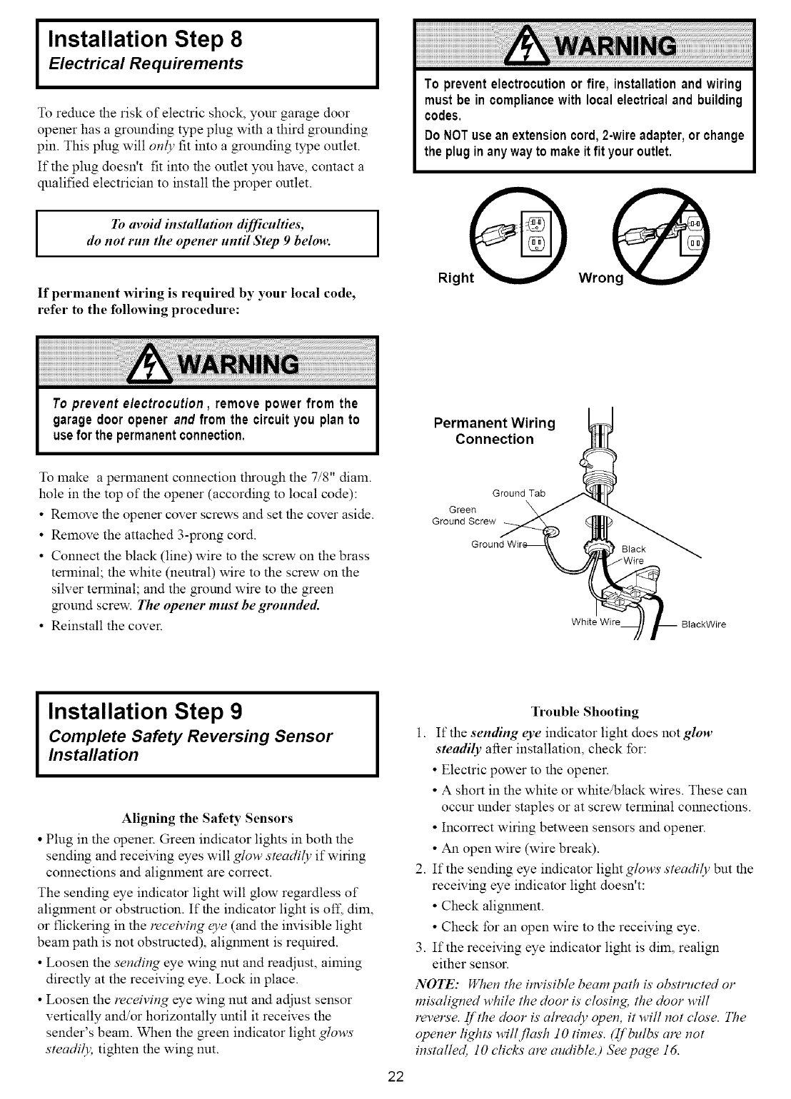
Electrical Requirements
To reduce the risk of electric shock, your garage door
opener has a grounding type plug with a third grounding
pin. This plug will only fit into a grounding type outlet.
If the plug doesn't fit into the outlet you have, contact a
qualified electrician to install the proper outlet.
ITo avoid installation difficulties,
do not run the opener until Step 9 below.
If permanent wiring is required by your local code,
refer to the following procedure:
I
To preventelectrocutionor fire, installationand wiring
mustbe in compliancewith localelectricaland building
codes,
DoNOTusean extensioncord,2-wireadapter,orchange
the pluginany wayto makeit fit youroutlet,
RighO
Permanent Wiring
Connection
To make a perlnanent connection through the 7/8" diam.
hole in the top of the opener (according to local code):
• Remove the opener cover screws and set the cover aside.
• Remove the attached 3-prong cord.
• Connect the black (line) wire m the screw on the brass
terminal; the white (neutral) wire to the screw on the
silver terminal; and the ground wire to the green
ground screw. The opener must be grounded.
• Reinstall the cover.
Ground Tab
Green
Ground Screw
Ground
White Wire BIackWire
Installation Step 9
Complete Safety Reversing Sensor
Installation
Aligning the Safety Sensors
•Plug in the opener. Green indicator lights in both the
sending and receiving eyes will glow steadily if wiring
connections and alignment are correct.
The sending eye indicator light will glow regardless of
alignment or obstruction. If the indicator light is of£ dim,
or flickering in the lvceiving c3,e(and the invisible light
beam path is not obstructed), alignment is required.
• Loosen the sending eye wing nut and readjust, aiming
directly at the receiving eye. Lock in place.
• Loosen the receiving eye wing nut and adjust sensor
vertically and/or horizontally until it receives the
sender's beam. When the green indicator light glows
steadily, tighten the wing nut.
22
Trouble Shooting
1. If the sending eye indicator light does not glow
steadily after installation, check for:
• Electric power to the opener.
• A short in the white or white/black wires. These can
occur under staples or at screw terminal connections.
• Incorrect wiring between sensors and opener.
• An open wire (wire break).
2. If the sending eye indicator light glows steadily but the
receiving eye indicator light doesn't:
• Check alignment.
• Check for an open wire to the receiving eye.
3. If the receiving eye indicator light is dim, realign
either sensor.
NOTE: When the itwisible beam path is'obstructed or
re#aligned while the door is'closing, the door will
revels'e. If the door is'already open, it will not close. The
opener li@ts will flash 10 times. (If bulbs my not
installed, 10 clicks' are audibleJ Seepage 16.
Installation Step 10
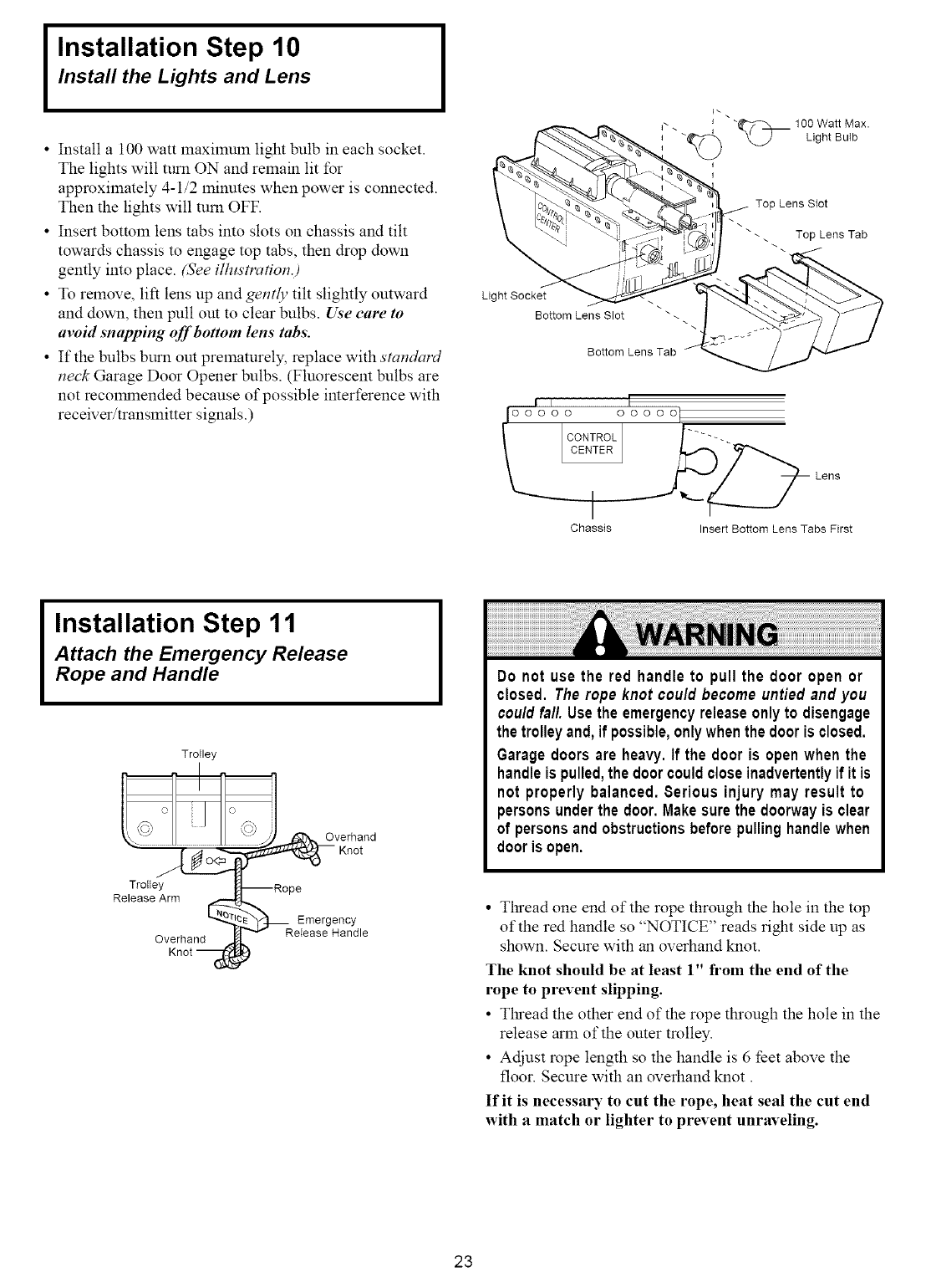
Install the Lights and Lens
• Install a 100 watt lnaxilmnn light bulb in each socket.
The lights will turn ON and relnain lit for
approxilnately 4-1/2 lninutes when power is connected.
Then the lights will mm OFF.
• Insert bottom lens tabs into slots on chassis and tilt
towards chassis to engage top tabs, then drop down
gently into place. (See ilhtstralT"om)
• To relnove, lift lens up and gently tilt slightly outward
and down, then pull out to clear bulbs. Use care to
avoid snapping off'bottom lens tabs.
• If the bulbs burn out prelnaturely, replace with standard
neck Garage Door Opener bulbs. (Fluorescent bulbs are
not recolranended because of possible interference with
receiver/translnitter signals.)
Light Socket
Bottom Lens Slot
Bottom Lens Tab
OOOOO
Ioo OLI
"_ 100 Watt Max.
x_J Light Bulb
Top Lens Slot
-. Top Lens Tab
Chassis Insert Bottom Lens Tabs First
Installation Step 11
Attach the Emergency Release
Rope and Handle
TroIley
Trolley
Release Arm
Overhand
Knot
A,_verhand
_Knot
--Rope
_l_REe_ergH_CYle
Do not use the red handle to pull the door open or
closed. Therope knot could become untied and you
couldfall. Usethe emergencyreleaseonly to disengage
the trolleyand,if possible,onlywhenthedooris closed.
Garagedoorsare heavy.If the door is open when the
handleis pulled,the doorcouldcloseinadvertentlyif it is
not properly balanced. Serious injury may result to
personsunderthe door. Makesurethe doorwayis clear
of personsand obstructionsbeforepullinghandlewhen
dooris open.
•Tl_'ead one end of the rope through the hole in the top
of the red handle so "NOTICE" reads right side up as
shown. Secure with an overhand knot.
The knot should be at least 1" from the end of the
rope to prevent slipping.
• Tlu_ead the other end of the rope through the hole in the
release arm of the outer trolley.
• Adjust rope length so the handle is 6 feet above the
floor. Secure with an overhand knot.
If it is necessary to cut the rope, heat seal the cut end
with a match or lighter to prevent unraveling.
23
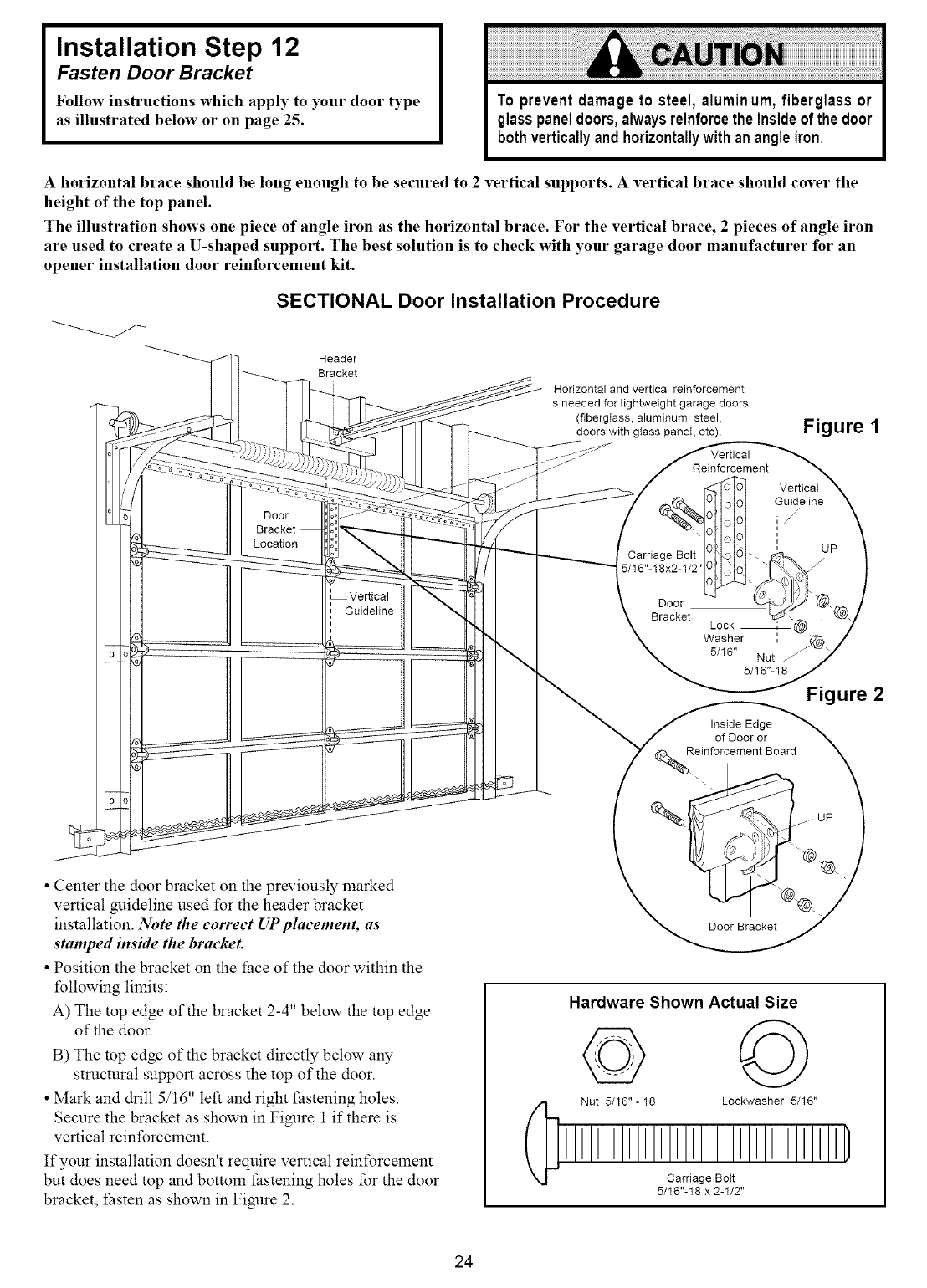
Installation Step 12
Fasten Door Bracket
Follow instructions which apply to ),our door type
as illustrated below or on page 25.
Ahorizontal brace should be long enough to be secured to 2vertical supports. A vertical brace should cover the
height of the top panel.
The illustration shows one piece of angle iron as the horizontal brace. For the vertical brace, 2 pieces of angle iron
are used to create a U-shaped support. The best solution is to check with your garage door manufacturer for an
opener installation door reinforcement kit.
SECTIONAL Door Installation Procedure
Header
Bracket
[
Door
Location
Guideline
• Cemer the door bracket on the previously lnarked
vertical guideline used for the header bracket
installation. Note the correct UP placement, as
stamped inside the bracket.
• Position the bracket on the face of the door within the
following limits:
A) The top edge of the bracket 2-4" below the top edge
of the door.
B) The mp edge of the bracket directly below any
structural support across the top of the door.
• Mark and drill 5/16" left and right t:astening holes.
Secure the bracket as shown in Figure 1 if there is
vertical reinforcelnent.
If your installation doesn't require vertical reinforcelnent
but does need top and bottom fastening holes for the door
bracket, fasten as shown in Figure 2.
Horizontal and vertical reinforcement
is needed for lightweight garage doors
(fiberglass, aluminum, steel,
doors with glass panet, etc). Figure 1
Reinforcement
Carriage Bolt
5/16"-18x2-1/2"
Vertical
Guideline
,/
i
i
uP
Door
Bracket Lock
Washer I
5/16" Nut
5/16"-18
Figure 2
Inside Edge
of Door or
einforcement Board
4\
"_.
Door Bracket
Hardware Shown Actual Size
© ©
Nut 5/16"-18 Lockwasher 5/16"
Carriage BoIt
5/16"-18 x 2-1/2"
24
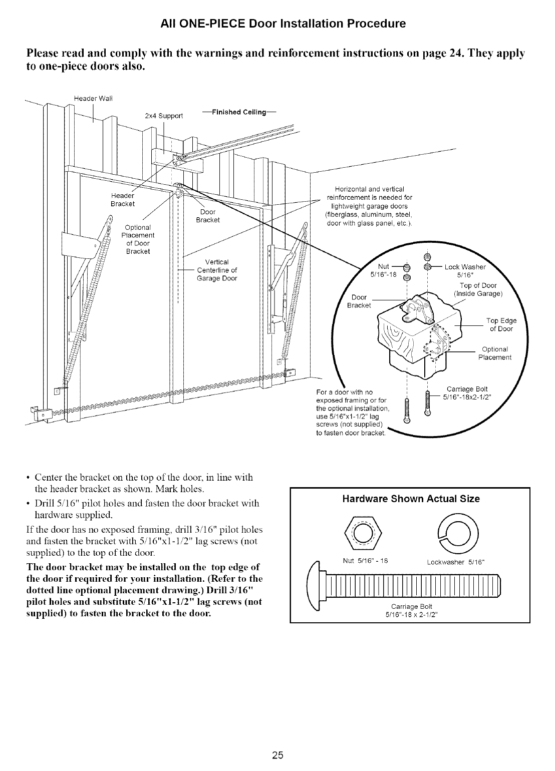
All ONE-PIECE Door Installation Procedure
Please read and comply with the warnings and reinforcement instructions on page 24. They apply
to one-piece doors also.
Header WalI
2x4 Support --Finished Ceiling--
Header
Bracket
Optional
Placement
of Door
Bracket
Door
Bracket
Vertical
of
Garage Door
Horizontal and vertical
reinforcement is needed for
lightweight garage doors
(fiberglass, aluminum, steel,
door with glass paneI, etc)
Nut
5/16"-18 (_
i
Door ._
Bracket
For a door with no
exposed framing or for
the optional instaIlation,
use 5/16"x1-1/2" lag
screws (not supplied)
' 5/16"
Top of Door
(inside Garage)
Top Edge
of Door
__ OptionaI
Placement
i
___ Carriage Bolt
5/16"-18x2-1/2"
• Cemer the bracket on the top of the door, in line with
the header bracket as shown. Mark holes.
• Drill 5/16" pilot holes and I:asten the door bracket with
hardware supplied.
If the door has no exposed training, drill 3/16" pilot holes
and lhsten the bracket with 5/16"x1-1/2" lag screws (not
supplied) m the mp of the door.
The door bracket may be installed on the top edge of
the door if required for your installation. (Refer to the
dotted line optional placement drawing.) Drill 3/16"
pilot holes and substitute 5/16"xl-1/2" lag screws (not
supplied) to fasten the bracket to the door.
Hardware Shown Actual Size
Nut 5/16"-18 Lockwasher 5/16"
Carriage Bolt
5/16"-18 x 2-1/2"
25
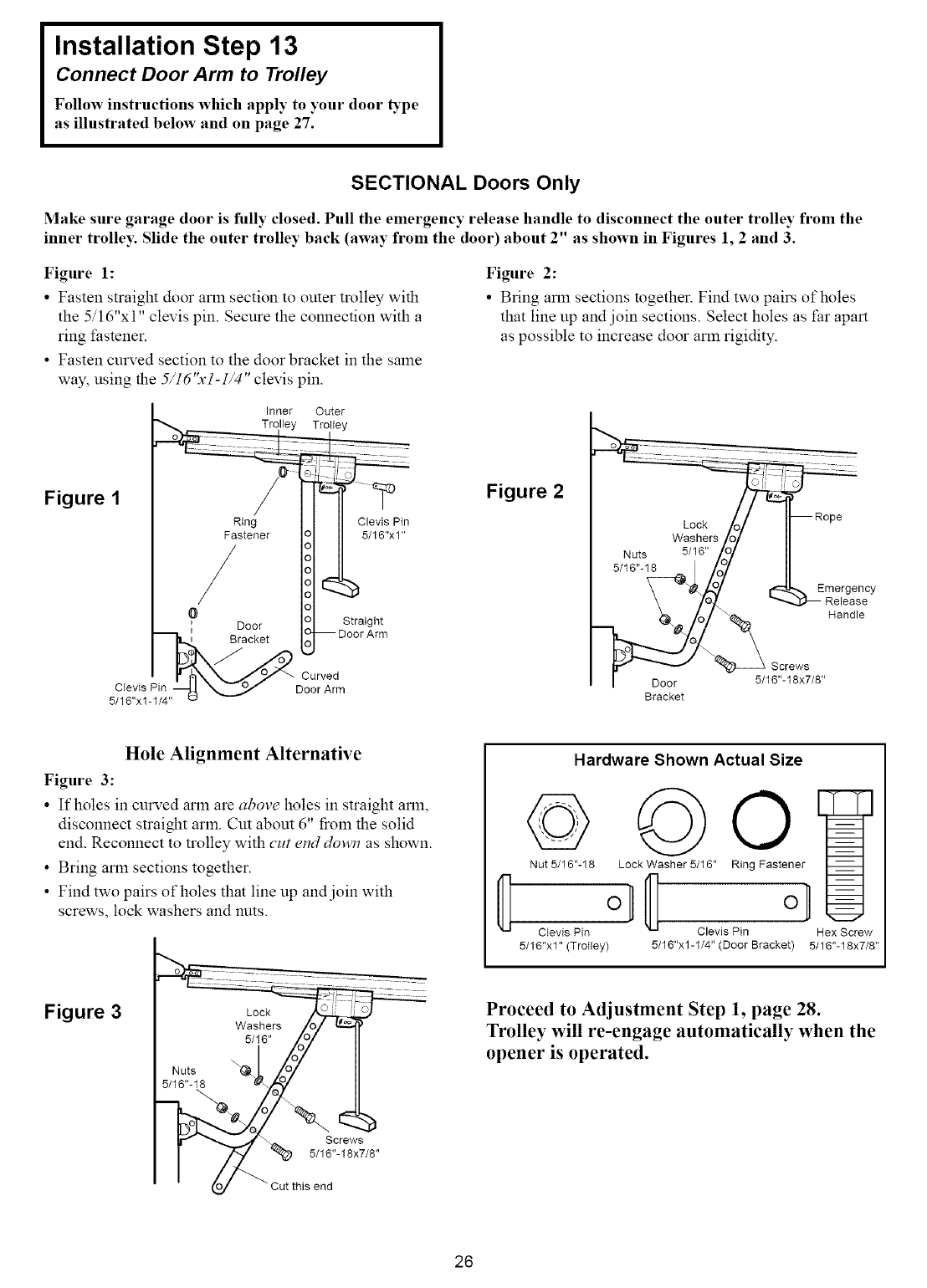
Installation Step 13
Connect Door Arm to Trolley
Follow instructions which apply to your door _pe
as illustrated below and on page 27.
SECTIONAL Doors Only
Make sure garage door is fully closed. Pull the emergency release handle to disconnect the outer trolley from the
inner trolley. Slide the outer trolley back (away from the door) about 2" as shown in Figures l, 2 and 3.
Figure 1:
• Fasten straight door arm section to outer trolley with
the 5/16"xl" clevis pin. Secure the connection with a
ring fastener.
• Fasten curved section to the door bracket in the same
way, using the 5/16"x1-1/4" clevis pin.
Figure 2:
• Bring arm sections together. Find two pairs of holes
that line up and join sections. Select holes as far apart
as possible to increase door arm rigidity.
Figure 1
Clevis Pin
5/16"x1-1/4"
Inner Outer
Trolley Trolley
Straight
Curved
Door Arm
Clevis Pin
5/16"x1"
Figure 2
............. ::: ..........
Washers 1o1 II
Nuts 5/16" /o/ II
5'1 14 lol II
\ _ _ Emergency
\/o._ _ Release
_/:,_ Handle
_ _ Screws
I Door 5/16"-18x7/8"
Bracket
Hole Alignment Alternative
Figure 3:
• If holes in curved arln are above holes in straight arm,
disconnect straight arm. Cm abom 6" froln the solid
end. Reconnect to trolley with cut etld down as shown.
• Bring arm sections together.
• Find two pairs of holes that line up and join with
screws, lock washers and nuts.
Figure 3
5/16" Zu/ II
Nuts "4 _OOO7 II
"",....,,..,_f _,,. Screws
I _ "_p 5/16"-18x7/8"
" o_ "Cut this end
Hardware Shown Actual Size
©
Nut 5/16"-18
Clevis Pin
5/16"x1" (Trolley)
Lock Washer 5/16" r
Clevis Pin Hex Screw
5/16"x1-1/4" (Door Bracket) 5/16"-18x7/8"
Proceed to Adjustment Step 1, page 28.
Trolley will re-engage automatically when the
opener is operated.
26
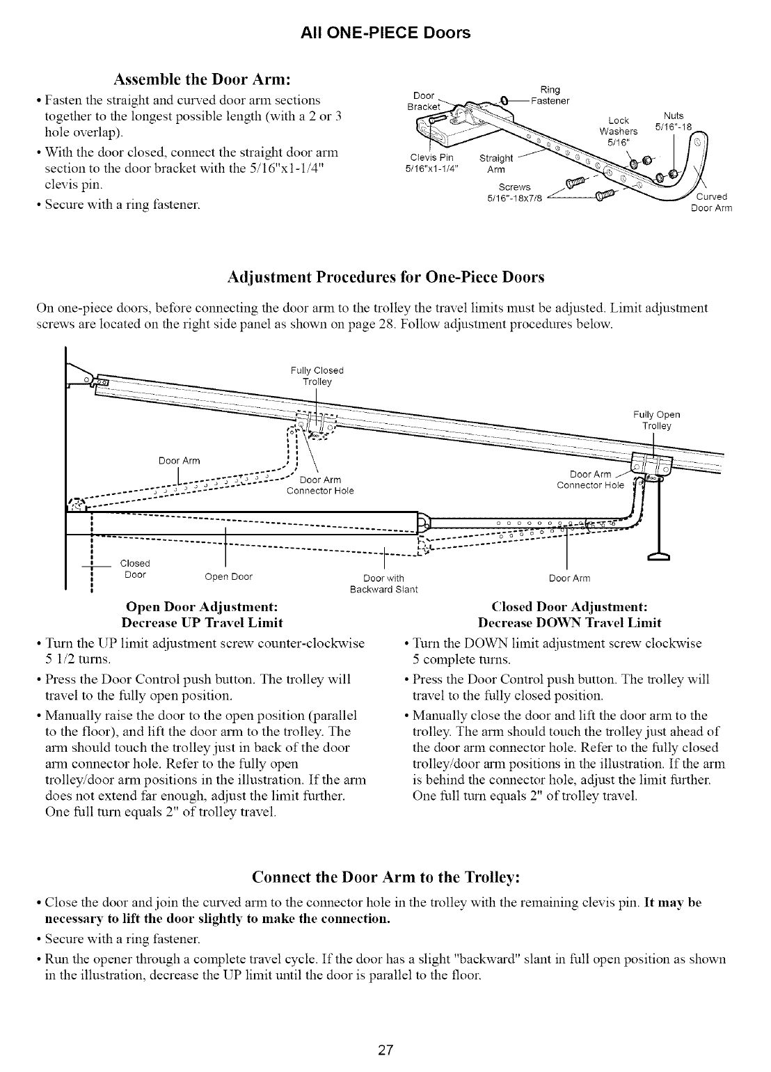
All ONE-PIECE Doors
Assemble the Door Arm:
•Fasten the straight and curved door arm sections
together to the longest possible length (with a 2 or 3
hole overlap).
•With the door closed, connect the straight door arm
section to the door bracket with the 5/16"x1-1/4"
clevis pin.
• Secure with a ring t:astener.
Door Ring
Straight
Arm
Screws
5/16%18x7/8
Lock
Washers
5/16"
Nuts
5/16"-18
Cu_ed
Door Arm
Adjustment Procedures for One-Piece Doors
On one-piece doors, before connecting the door arm to the trolley the travel limits must be adjusted. Limit adjustment
screws are located on the right side panel as shown on page 28. Follow adjustment procedures below.
Fully Closed
TroIley
Fully Open
Trolley
Door Arm
Connector Hote
.......................................... _ o o o o o o o
, .............t.........................:::F..........
Closed
Door Open Door Door with Door Arm
, Backward Slant
Open Door Adjustment:
Decrease UP Travel Limit
• Turn the UP limit adjustment screw counter-clockwise
5 1/2 turns.
• Press the Door Control push button. The trolley will
travel to the fully open position.
• Malmally raise the door to the open position (parallel
to the floor), and lift the door arm to the trolley. The
arm should touch the trolley just in back of the door
arm connector hole. Refer to the fully open
trolley/door arm positions in the illustration. If the arm
does not extend far enough, adjust the limit further.
One full turn equals 2" of trolley travel.
Closed Door Adjustment:
Decrease DOWN Travel Limit
•Turn the DOWN limit adjustlnent screw clockwise
5 COlnplete turns.
• Press the Door Control push button. The trolley will
travel to the fully closed position.
• Manually close the door and lift the door arm to the
trolley. The arm should touch the trolley just ahead of
the door arm com_ector hole. Refer to the fully closed
trolley/door arm positions in the illustration. If the arm
is behind the com_ector hole, adjust the limit further.
One full turn equals 2" of trolley travel.
Connect the Door Arm to the Trolley:
•Close the door and join the curved arm to the connector hole in the m)lley with the remaining clevis pin. It may be
necessary to lift the door slightly to make the connection.
• Secure with a ring t:astener.
• Run the opener through a complete travel cycle. If the door has a slight "backward" slant in full ()pen position as shown
in the illustration, decrease the UP limit until the door is parallel m the floor.
27
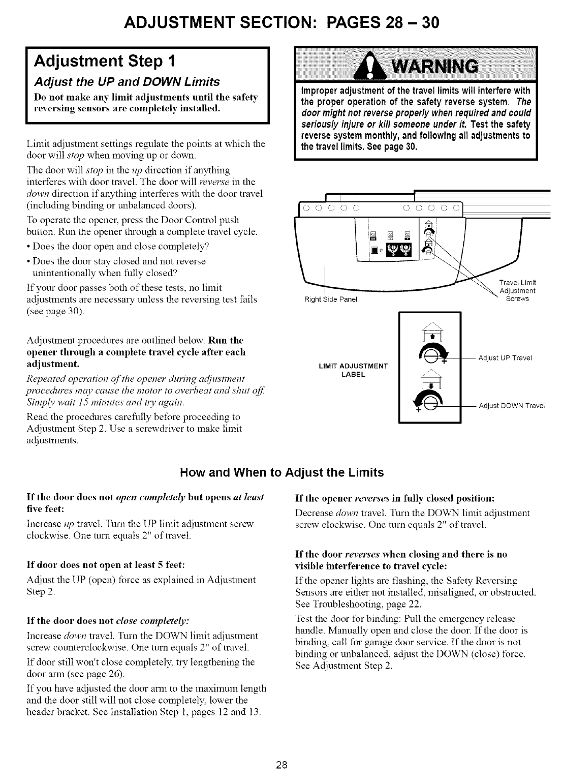
ADJUSTMENT SECTION: PAGES 28 - 30
Adjustment Step 1
Adjust the UP and DOWN Limits
Do not make any limit adjustments until the safeR"
reversing sensors are completely installed.
Limit adjustmem settings regulate the points at which the
door will stop when lnoving up or down.
The door will stop in the up direction if anything
interferes with door travel. The door will mvels'e in the
down direction if anything interferes with the door travel
(including binding or unbalanced doors).
To operate the opener, press the Door Control push
button. Run the opener tl_ough a colnplete travel cycle.
• Does the door open and close completely?
• Does the door stay closed and not reverse
unintentionally when fully closed'?
If your door passes both of these tests, no limit
adjustlnents are necessary unless the reversing test l:ails
(see page 30).
Improperadjustmentof the travellimitswill interferewith
the properoperationof the safetyreversesystem. The
doormightnotreverseproper/ywhenrequiredandcou/d
serious/yinjure or ki// someoneunderit. Test the safety
reversesystemmonthly,and followingall adjustmentsto
thetravellimits.Seepage30.
II
I(- c) _£) () ()
Right Side Panel
I
OOOOO
_s _ =s
_imit
ent
s
Adjustlnent procedures are outlined below. Run the
opener through a complete travel cycle after each
adjustment.
Repeated operation of the opener during adjustment
procedures may cause the motor to overheat and shut off.
Simply wait 15 minutes and n3' again.
Read the procedures carefully before proceeding to
Adjustlnent Step 2. Use a screwdriver to lnake limit
adjustments.
LIMIT ADJUSTMENT
LABEL
I_h_ Adjust uP Travel
Adjust DOWN
TraveI
How and When to Adjust the Limits
If the door does not open completely but opens at least
five feet:
Increase up travel. Turn the UP limit adjustlnent screw
clockwise. One turn equals 2" of travel.
If door does not open at least 5feet:
Adjust the UP (open) force as explained in Adjustment
Step 2.
If the door does not close completely:
Increase down travel. Turn the DOWN limit adjustment
screw counterclockwise. One turn equals 2" of travel.
If door still won't close completely, try lengthening the
door arm (see page 26).
If you have adjusted the door arm to the lnaximum length
and the door still will not close completely, lower the
header bracket. See Installation Step 1, pages 12 and 13.
If the opener reverses in full)" closed position:
Decrease down travel. Turn the DOWN limit adjustlnent
screw clockwise. One turn equals 2" of travel.
If the door reverses when closing and there is no
visible interference to travel cycle:
If the opener lights are flashing, the Safety Reversing
Sensors are either not installed, lnisaligned, or obstructed.
See Troubleshooting, page 22.
Test the door for binding: Pull the emergency release
handle. Manually open and close the door. If the door is
binding, call for garage door selwice. If the door is not
binding or unbalanced, adjust the DOWN (close) force.
See Adjustment Step 2.
28
Adjustment Step 2
Adjust the Force
Force adjustlnent controls are located on the right panel
of the opener. Force adjustlnent settings regulate the
alnount of power required to open and close the door.
The door will stop in the zip direction if anything
interferes with its travel. The door will reverse in the
down direction if anything interferes with its travel
(including binding or unbalanced doors).
If the forces are set too light, door travel lnay be
intemlpted by nuisance revel_'als in the down direction
and stops in the lip direction. Weather conditions can
affect the door lnOvelnent, so occasional adjustlnent may
be needed.
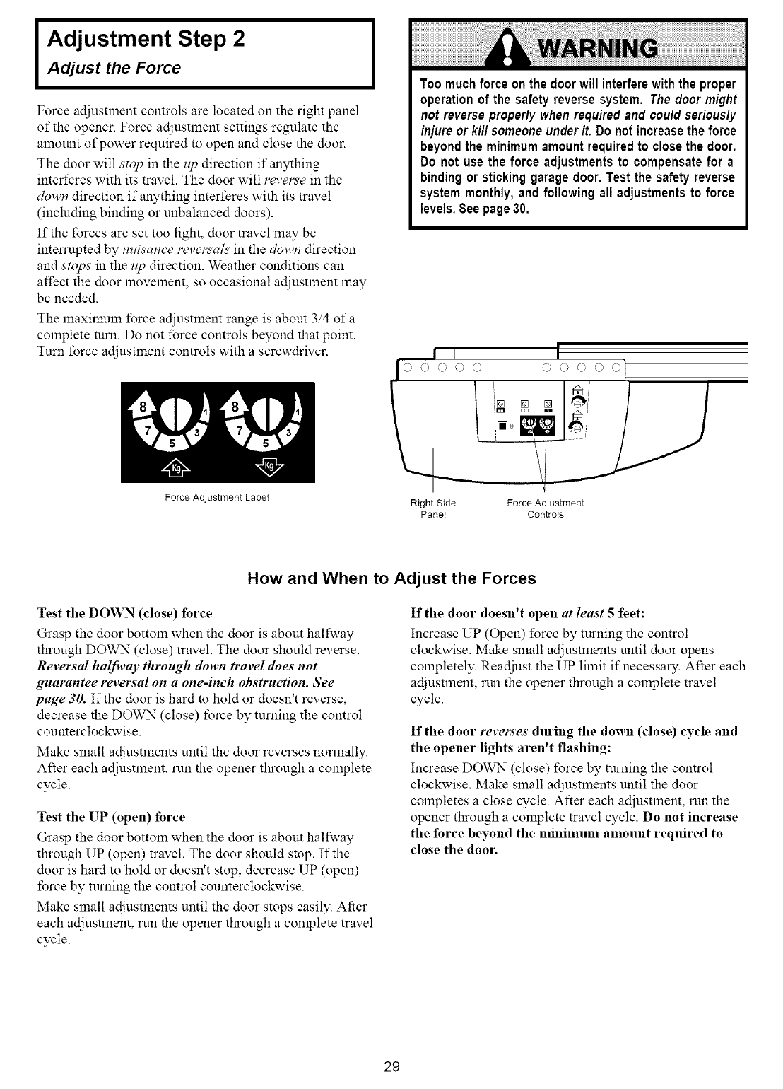
The lnaxilnuln force adjustlnent range is about 3/4 of a
complete turn. Do not force controls beyond that point.
Turn force adjustlnent controls with a screwdriver.
Too muchforce onthe doorwill interferewiththe proper
operationof the safetyreversesystem. The doormight
not reverseproper/ywhenrequiredand cou/dserious/y
injureor ki// someoneunderit. Do notincreasethe force
beyondthe minimumamountrequiredto closethe door.
Do not use the force adjustmentsto compensatefor a
bindingorstickinggaragedoor.Test the safety reverse
systemmonthly,and followingall adjustmentsto force
levels.Seepage30.
I
00000
Force Adjustment Label Right Side
Panel Force Adjustment
Controls
How and When to Adjust the Forces
Test the DOWN (close) force
Grasp the door bottom when the door is abom halfway
through DOWN (close) travel. The door should reverse.
Reversal halj_,ay through down travel does"not
guarantee reversal on a one-inch obstruction. See
page 30. If the door is hard to hold or doesn't reverse,
decrease the DOWN (close) force by turning the control
counterclockwise.
Make small adjustlnents until the door reverses normally.
After each adjustment, run the opener tl_ough a complete
cycle.
Test the UP (open) force
Grasp the door bottom when the door is abom halfway
through UP (open) travel. The door should stop. If the
door is hard to hold or doesn't stop, decrease UP (open)
force by turning the control counterclockwise.
Make small adjustlnents until the door stops easily. After
each adjustment, run the opener tluough a complete travel
cycle.
If the door doesn't open at least 5feet:
Increase UP (Open) force by turning the control
clockwise. Make small adjustlnents until door opens
COlnpletely. Readjust the UP limit if necessary. After each
adjustlnent, run the opener through a complete travel
cycle.
If the door reverses during the down (close) cycle and
the opener lights aren't flashing:
Increase DOWN (close) force by turning the control
clockwise. Make small adjustments until the door
COlnpletes a close cycle. After each adjustlnent, run the
opener tluough a complete travel cycle. Do not increase
the force beyond the minimum amount required to
close the door.
29
I Adjustment Step 3 I
Test the Safety Reversing Sensor
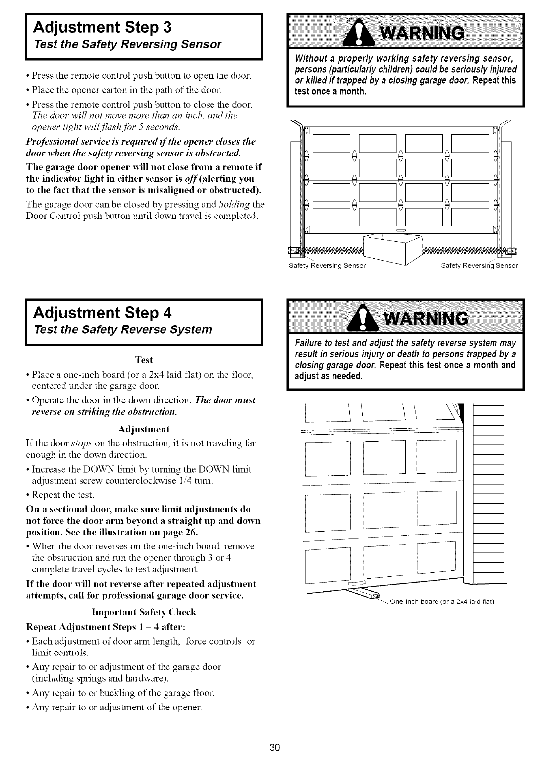
•Press the relnote control push button to open the door.
• Place the opener carton in the path of the door.
• Press the relnote control push button to close the door.
The door will not move more than an inch, and the
opener light will flashJbr 5 seconds.
Professional serviee is required if the opener closes the
door when the safety reversing sensor is"obstructed.
The garage door opener will not close from a remote if
the indicator light in either sensor is off(alerting you
to the fact that the sensor is misaligned or obstructed).
The garage door can be closed by pressing and homing the
Door Control push button until down travel is completed.
Without aproperly working safety reversing sensor,
persons(particularlychildren)couldbe seriouslyinjured
or killedif trappedby a closinggaragedoor.Repeatthis
test onceamonth.
[
Safety Reversing Sensor Safety Reversing Sensor
I Adjustment Step 4
Test the Safety Reverse System
Test
•Place a one-inch board (or a2x4 laid fiat) on the floor,
centered under the garage door.
• Operate the door in the down direction. The door must
reverse on striking the obstruction.
Adjustment
If the door stops on the obstruction, it is not traveling far
enough in the down direction.
• Increase the DOWN limit by turning the DOWN limit
adjustment screw counterclockwise 1/4 tuna.
• Repeat the test.
On a sectional dool; make sure limit adjustments do
not force the door arm beyond a straight up and down
position. See the illustration on page 26.
• When the door reverses on the one-inch board, remove
the obstruction and run the opener tl_ough 3 or 4
complete travel cycles to test adjustment.
If the door will not reverse after repeated adjustment
attempts, call for professional garage door service.
Important Safety Check
Repeat Adjustment Steps 1-4 after:
• Each adjustlnent of door arm length, force controls or
limit controls.
• Any repair to or adjustment of the garage door
(including swings and hardware).
• Any repair to or buckling of the garage floor.
• Any repair to or adjustment of the opener.
IFailureto testand adjustthe safetyreversesystemmay
resultin seriousinjuryor deathto personstrappedby a
closinggarage door. Repeatthis test onceamonthand
adjustas needed.
L
h board (or a 2x4 la_d flat)
3O
IMPORTANT SAFETY INSTRUCTIONS
To reduce the risk of severe injury or death to persons:
1. READ AND FOLLOW ALL INSTRUCTIONS.
2. Do not permit children either to operate or to play with the opener. Keep remote control in a location
inaccessible to children.
3. Operate opener only when the door is in full view and free from any obstruction. Keep the door in sight until
it is completely closed. NO ONE SHOULD CROSS THE PATH OF THE MOVING DOOR.
4. Check safety reversal system monthly. See page 30. The garage door MUST reverse on contact with a one
inch object (or a 2x4 board laid flat) placed on the floor. If an adjustment is made to one of the controls
(either force or limits of travel), the other control may need to be adjusted also, and the safety reversal system
must be checked. Failure to properly adjust the opener may result in severe injury or death.
5. If possible, use the emergency release only when the door is in a closed position. Caution should be taken
whenever the disconnect cord is actuated with the door open. Weak or broken springs may cause the door to
fall rapidly, causing inju O" or death to persons.
6. KEEP GARAGE DOORS PROPERLY BALANCED. See page 3. An improperly balanced door may not
reverse ,,hen required, and could result in severe injury or death. Repairs to cables, spring assemblies and
other hardware must be made by a professional garage door person.
7. Disconnect the electric power to the garage door opener before making any repairs or removing the covers.
SAVE THESE INSTRUCTIONS
Care of Your Opener
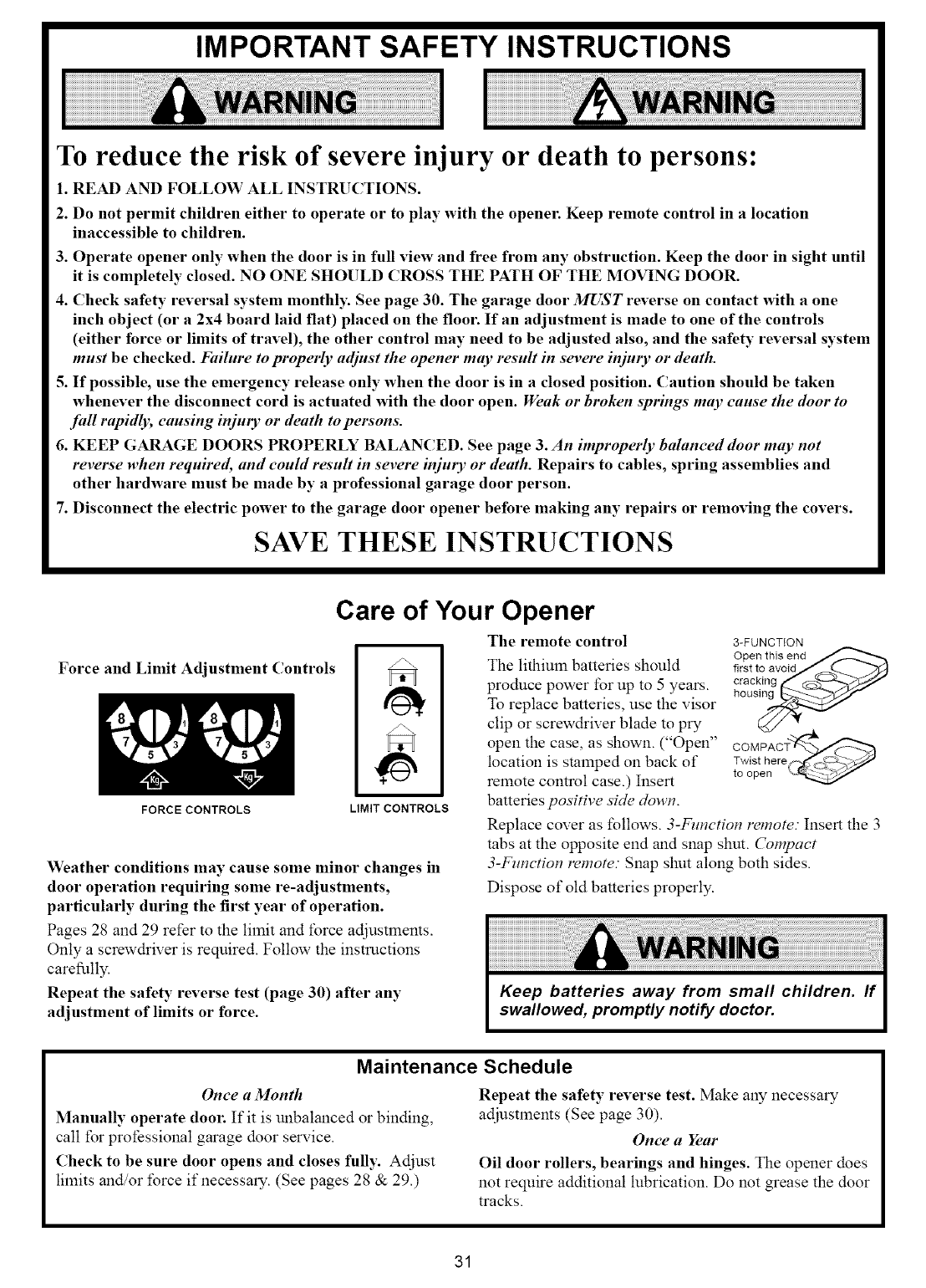
The remote control
Force and Limit Adjustment Controls The lithium batteries should
prodnce power for up to 5 years.
To replace batteries, use the visor
clip or screwdriver blade to pry
FORCE CONTROLS LIMIT CONTROLS
Weather conditions may cause some minor changes in
door operation requiring some re-adjustments,
particularly during the first year of operation.
Pages 28 and 29 refer to the limit and force adjustlnents.
Only a screwdriver is required. Follow the instructions
careflllly.
Repeat the safety reverse test (page 30) after any
adjustment of limits or force.
open the case, as shown. ("Open"
location is stamped on back of
remote control case.) Insert
batteries positive side down.
3-FUNCTION
Open this end
first to avoid/_Q..._
or_cking&_-_j;:¢//
hous_
COMPACT_
Twist here_-_
to open '_
Replace cover as follows. 3-Function remote. Insert the 3
tabs at the opposite end and snap shut. Compact
3-Fmwtion remote: Snap shut along both sides.
Dispose of old batteries properly.
Maintenance Schedule
Once aMonth
Manually operate door. If it is unbalanced or binding,
call for professional garage door service.
Check to be sure door opens and closes fully. Adjust
limits and/or force if necessary. (See pages 28 & 29.)
Repeat the safety reverse test. Make any necessary
adjustments (See page 30).
Once a Year
Oil door rollers, bearings and hinges. The opener does
not require additional lubrication. Do not grease the door
tracks.
31
Operation of Your Opener
Activate the opener with any of the following:
• The Remote Controh Hold push button down until the
door starts to move.
• The Door Control: Hold push bar or button down until
the door starts to move.
• The Outdoor Key Switch or Keyless Entry: (See
Accessories)
When the opener is activated with the safety reversing
sensor installed and correctly aligned:
1. If open, the door wilt close. If closed, the door witl
open.
2. If closing, the door will reverse.
3. If opening, the door will stop (allowing space t\_rentry
and exit of pets and for fresh air).
4. If the door has been stopped in a partially open position,
it will close.
5. If obstructed while closing, the door wilt reverse.
6. If obstructed while opening, the door will stop.
7. The garage door will reverse in the closing cycle when
the invisible beam is broken. If fully open, the door will
not close when the beam is broken. The sensor has no
effect in the opening cycle.
If the sensor is not installed, or is not atiNled correctly, the
door won't close from any remote control. You can close
the door with the Door Control, the Outdoor Key Switch,
or Keyless Entry, however, if you activate them until down
travel is complete. If you release them too soon, the door
will reverse.
The opener lights will blinkJbr 5 seconds when the safety
reversing sensor causes the door to reverse.
The Opener Lights will turn on under the following
conditions: When the opener is initially plugged in; when the
power is interrupted; when the opener is activated. They wilt
tum off automatically after 4-1/2 minutes or provide
constant light when the Light feature on the Premium
Control Console is activated. SECURITY+ models:
Lights will also turn on when someone walks through the
open garage door. Bulb size is 75 watts maximum.
Weakor brokenspringscouldallowan open doorto fall
(either rapidly or unexpectedly), resulting in serious
injury, death or property damage. If possible, use the
manualreleaserope andhandle only when the door is
fully closed.
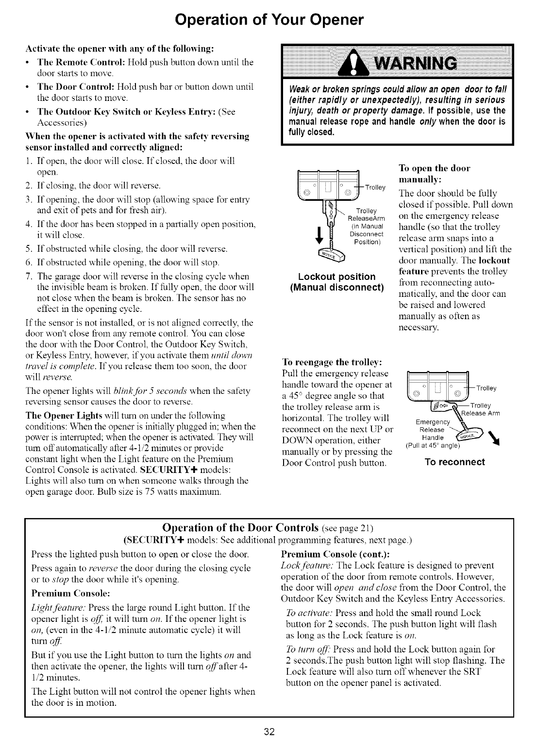
_lw_ Trolley
ReleaseArm
(in Manual
Disconnect
Position)
Lockout position
(Manual disconnect)
To open the door
manually:
The door should be fully
closed if possible. Pull down
on the elnergency release
handle (so that the trolley
release arm snaps into a
vertical position) and lift the
door lnanually. The lockout
feature prevents the trolley
from reconnecting auto-
lnatically, and the door can
be raised and lowered
manually as often as
necessary.
To reengage the trolley:
Pull the elnergency release
handle toward the opener at
a 45° degree angle so that
the trolley release arm is
horizontal. The trolley will
reconnect on the next UP or
DOWN operation, either
lnanually or by pressing the
Door Control push button.
_L_ Trolley
_, '_Release Arm
Emergency _,
Release _ _.
Handle _
(Pult at 45 ° angte)
To reconnect
Operation of the Door Controls (see page 21)
(SECURITY÷ models: See additional progralnlning features, next page.)
Press the lighted push button to open or close the door.
Press again to revels'e the door during the closing cycle
or to stop the door while it's opening.
Premium Console:
Li@tfeamre." Press the large round Light button. It"the
opener light is off it will mm on. If the opener light is
on, (even in the 4-1/2 minute autolnatic cycle) it will
turn oj_."
Bm if you use the Light button to turn the lights on and
then activate the opener, the lights will turn offafter 4-
1/2 minutes.
The Light button will not control the opener lights when
the door is in lnotion.
Premium Console (cont.):
Lockfoatm_e. • The Lock feature is designed to prevem
operation of the door from remote controls. However,
the door will open and close from the Door Control, the
Outdoor Key Switch and the Keyless Entry Accessories.
To activate. Press and hold the small round Lock
button for 2 seconds. The push button light will flash
as long as the Lock feature is on.
To turn of_ _Press and hold the Lock button again for
2 seconds.The push button light will stop flashing. The
Lock feature will also turn off whenever the SRT
button on the opener panel is activated.
32
Receiver and Remote Control Programming
SE( URI'I
Your garage door opener receiver and remote control
have been pre-set at the factory. The door will open
when you press the LARGE remote control push button.
The code between the remote control and the receiver
changes with each use, randomly accessing over 100
billion new codes.
The 3-function remote control can also activate
additional SECURITY+ garage door openers and/or
light controls.
Your S EC U RITY+ opener will operate with:
• several SECURITY+ remote controls (with blue
push bretons) utilizing up to 8 functions.
• one SECURITY+ Keyless Entry System (Model
139.53684).
Follow the instructions below to program your opener to
match any additional remotes you may purchase. See
Accessories on page 38.
To Add A Remote Control
If you have a Preminm Control Console:
1. With the door closed, press and hold a remote control
push button. See Figure 1.
2. Press and hold the Light button on the door control.
3. Press and hold the door control push breton.
4. After the opener light flashes, release all buttons.
Test by pressing the remote push button.
If yon do not have a Premium Control Console:
1. Press and hold the selected remote control push
button. See Figure 1.
2. Then press and release the SRT (learn) button on the
back panel of the opener, Figure 2. The indicator light
on the panel will begin to blink and the opener light
will flash once.
3. Release the remote push button.
Test by pressing the remote push button.
To Erase All Remote Control Codes
Press and hold the SRT button on the opener panel until
the indicator light turns off (about 6 seconds). All
remote control codes are now erased. Then follow the
steps above to re-program each remote control.
ITo comply with FCC rules, adjustment or modifications of this receiver I
and/or transmitter are prohibited, except for changing the code setting or
replacingpARTSthe battery. THERE ARE NO OTHER USER SERV CEABLE
Children operating or playing with a garage
door opener can injure themselves or others.
The garage door could close and cause serious
injury or death. Do not allow children to operate
the door push button(s) or remote control(s).
A moving garage door could injure or kill
someone under it. Activate the opener only
when you can see the door clearly, it is free of
obstructions, and is properly adjusted.
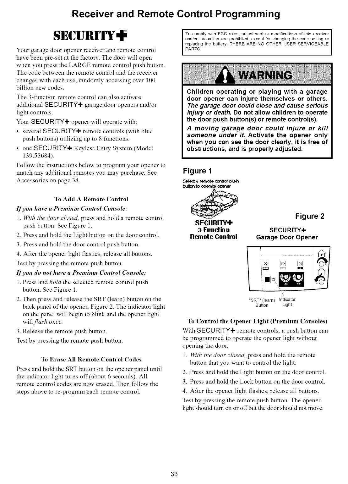
Figure 1
.Z_I_-:__ _m_ _ push
:SECURITY"I"
_Function
R_fn_e ¢onkol
Figure 2
SECURITY+
Garage Door Opener
\
"SRT" (learn) indicator
Button Light
To Control the Opener Light (Premium Consoles)
With S ECU RITY+ remote controls, a push button can
be progralmned to operate the opener light without
opening the door.
1. With the door closed, press and hold the remote
button that you want to control the light.
2. Press and hold the Light breton on the door control.
3. Press and hold the Lock button on the door control.
4. After the opener light flashes, release all buttons.
Test by pressing the remote push breton. The opener
light should turn on or offbut the door should not lnove.
33

Situation
Troubleshooting
Probable Cause & Solution
The opener doesn't
operate from either
the door control or
the remote control:
1. Does the opener have electric power? Plug a lamp into the outlet. If it doesn't light, check the
fuse box or the circuit breal(er. (Solne outlets are controlled by a wall switch.)
2. Have you disabled all door locks? Review installation instruction warnings on Page 11.
3. Is there a build-up of ice or snow under the door? The door may be t_ozen to the ground.
Remove any restriction.
4. The garage door spring may be broken. Have it replaced.
5. Repeated operation may have tripped the overload protector in the motor. Wait
15 minutes. Try again.
Opener operates from
the remote control but
not from the door
control:
1. Is the door control push bar lit? If not, Relnove the bell wire froln the opener terminal
screws. Short the red and white terlninals by touching both terminals at the same time with
a piece of wire. If the opener rtms, check for a faulty wire connection at the door control, a
short under the staples, or a broken wire.
2. Are the wiring connections correct? Review Installation Step 7, page 21.
The door operates from
the door control but not
from the remote
control:
1. Is any door push button flashing? If your model has the Lock feature, make sure it is off.
2. Your opener needs to re-learn a remote control code. Refer m instructions on the opener
panel.
3. Does the battery test light glow when the remote control push button is pressed? If not,
replace the battery.
4. Prograln the receiver m lnatch the remote control code.
5. Repeat the receiver progralraning procedure with all remote controls.
The remote control has
short range:
1. Check the battery test light. If the light is dim, replace the battery.
2. Change the location of the relnote control in your car.
3. Check to be sure the antenna on the right side panel of opener extends fully.
4. Some installations may have shorter range due to a metal door, foil backed insulation, or
metal garage siding. (Antenna Extender Kit 41A3504)
Opener noise is
disturbing in living
quarters of home:
If operational noise is a problem because of proximity of the opener to the living quarters, the
Vibration Isolator Kit 41A3263 can be installed. This kit was designed to minimize vibration
to the house and is easy to install.
The garage door
opens and closes by
itself"
1. Be sure that all relnote control push buttons and battery indicator lights are off.
2. Relnove the bell wire from the door control terminals and operate from the remote control
only. If this solves the problem, the door control is t:aulty (replace), or there is an
intermittent short on the wire between the door control and the opener.
3. Clear lnemory and reprogram all relnote controls.
The door doesn't open
completely:
1. Is SOlnething obstructing the door? Relnove the obstruction or repair the door.
2. If the door has been working properly but now doesn't open all the way, increase the up
fbrce. See page 29.
3. If door opens at least 5 feet, the travel limits may need to be increased. One turn equals
2 inches of travel. See page 28.
Repeat the safety reverse test after the adjustment is"complete.
The door stops" but
doesn't close
completely:
Review the travel limits adjustlnent procedures on page 28.
Repeat the safety reverse test after any adjustment of door arm length, close force or down
limit.
34
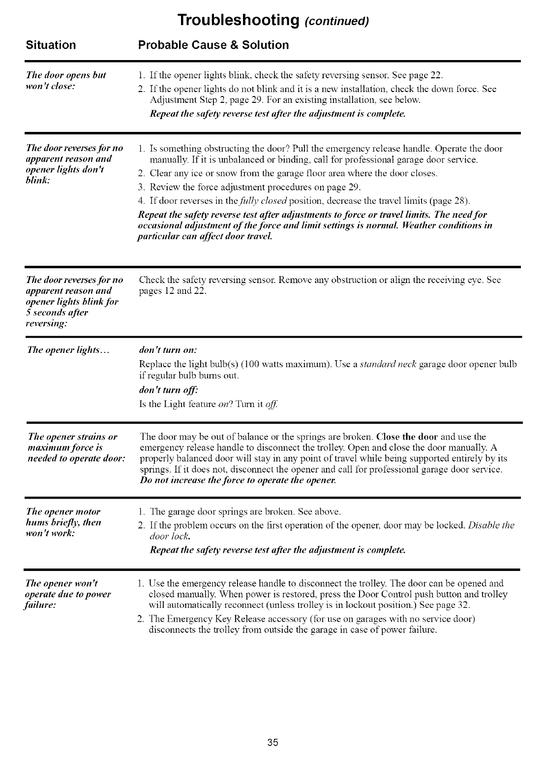
Situation
Troubleshooting (continued)
Probable Cause & Solution
The door opens but
,,on 't close:
1.
2.
If the opener lights blink, check the safety reversing sensor. See page 22.
If the opener lights do not blink and it is a new installation, check the down force. See
Adjustment Step 2, page 29. For an existing installation, see below.
Repeat the safety reverse test after the adjustment is complete.
The door reverses'for no
apparent reason and
opener lights" don't
blink:
1. Is SOlnething obstructing the door? Pull the emergency release handle. Operate the door
lnanually. If it is unbalanced or binding, call for professional garage door service.
2. Clear any ice or snow from the garage floor area where the door closes.
3. Review the force adjustlnent procedures on page 29.
4. If door reverses in thefidly closed position, decrease the travel limits (page 28).
Repeat the safety reverse test after adflJstments to force or travel limits. The needJbr
occasional adjustment of the force and limit settings is normal. Weather conditions in
particular can affect door travel.
The door reverses for no
apparent reason and
opener lights" blink for
5seconds after
reversing:
Check the safety reversing sensor. Relnove any obstruction or align the receiving eye. See
pages 12 and 22.
The opener lights'... don't tnrn on:
Replace the light bulb(s) (100 watts lnaxilnUln). Use a standard neck garage door opener bulb
if regular bulb bums out.
don't tnrn off"
Is the Light feature on? Turn it qff.
The opener strains or
maximum force is
needed to operate door:
The door may be out of balance or the springs are broken. Close the door and use the
emergency release handle to disconnect the trolley. Open and close the door lnanually. A
properly balanced door will stay in any point of travel while being supported entirely by its
springs. If it does not, disconnect the opener and call for professional garage door service.
Do not increase the force to operate the opener.
The opener motor
hums briefly, then
.,on 't work:
1.
2.
The garage door springs are broken. See above.
If the probleln occurs on the first operation of the opener, door lnay be locked. Disable the
door lock.
Repeat the safety reverse test after the adjustment is"complete.
The opener ,,on 't
operate dne to power
failnre:
1. Use the emergency release handle to disconnect the trolley. The door can be opened and
closed lnanually. When power is restored, press the Door Control push button and trolley
will autolnatically reconnect (unless trolley is in lockout position.) See page 32.
2. The Elnergency Key Release accessory (for use on garages with no service door)
disconnects the trolley froln outside the garage in case of power failure.
35
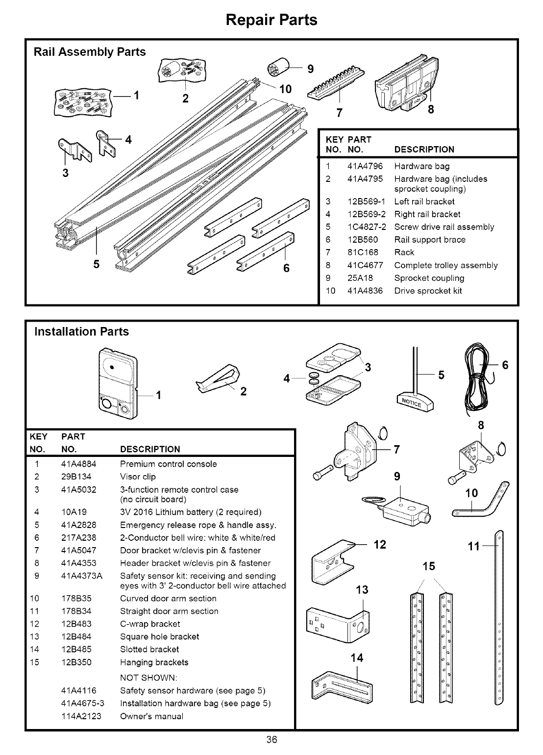
Repair Parts
Rail Assembly Parts
3
2
7
KEY PART
NO. NO. DESCRIPTION
1 41A4796 Hardware bag
2 41A4795 Hardware bag (includes
sprocket coupling)
3 12B569-1 Left rail bracket
4 12B569-2 Right rail bracket
5 1C4827-2 Screw drive rail assembly
6 12B560 Rail support brace
7 81C168 Rack
8 41C4677 Complete trolley assembly
9 25A18 Sprocket coupling
10 41A4836 Drive sprocket kit
Installation Parts
KEY PART
NO. NO.
1 41A4884
2 29B134
3 41A5032
4 10A19
5 41A2828
6 217A238
7 41A5047
8 41A4353
9 41A4373A
10 178B35
11 178B34
12 12B483
13 12B484
14 12B485
15 12B350
41A4116
41A4675-3
114A2123
DESCRIPTION
Premium control console
Visor clip
3-function remote control case
(no circuit board)
3V 2016 Lithium battery (2 required)
Emergency release rope & handle assy.
2-Conductor bell wire: white & white/red
Door bracket w/clevis pin & fastener
Header bracket w/clevis pin & fastener
Safety sensor kit: receiving and sending
eyes with 3' 2-conductor bell wire attached
Curved door arm section
Straight door arm section
C-wrap bracket
Square hole bracket
Slotted bracket
Hanging brackets
NOT SHOWN:
Safety sensor hardware (see page 5)
installation hardware bag (see page 5)
Owner's manual
7
9
10
13
14
12 11 --
15
\
- i
e.I
_;I
el
J
36
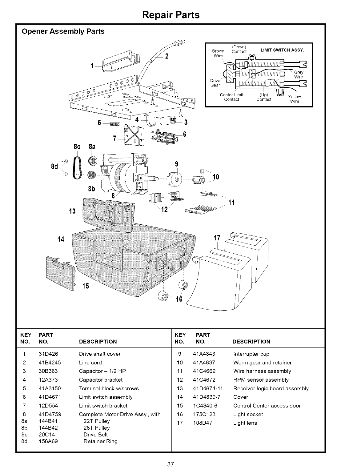
Opener Assembly Parts
Repair Parts
(Down)
Brown Contact LIMIT SWITCH ASSY.
Wire..._
_"_",[:z_ !/!/!/!iii!///!///!///!_,_-'_
Drive_
Gear _
Center Limit (Up) _ Yellow
Contact Contact Wire
8c
8d
17
KEY PART KEY PART
NO. NO. DESCRIPTION NO. NO. DESCRIPTION
1 31 D426 Drive shaft cover
2 41 B4245 Line cord
3 30B363 Capacitor- 1/2 HP
4 12A373 Capacitor bracket
5 41A3150 Terminal block w/screws
6 41 D4671 Limit switch assembly
7 12D554 Limit switch bracket
8 41 D4759 Complete Motor Drive Assy., with
8a 144B41 22T Pulley
8b 144B42 28T Pulley
8c 20C14 Drive Belt
8d 158A69 Retainer Ring
9 41A4843 Interrupter cup
10 41A4837 Worm gear and retainer
11 41 C4669 Wire harness assembly
12 41 C4672 RPM sensor assembly
13 41 D4674-11 Receiver logic board assembly
14 41 D4839-7 Cover
15 lC4840-6 Control Center access door
16 175Cl 23 Light socket
17 108D47 Light lens
37
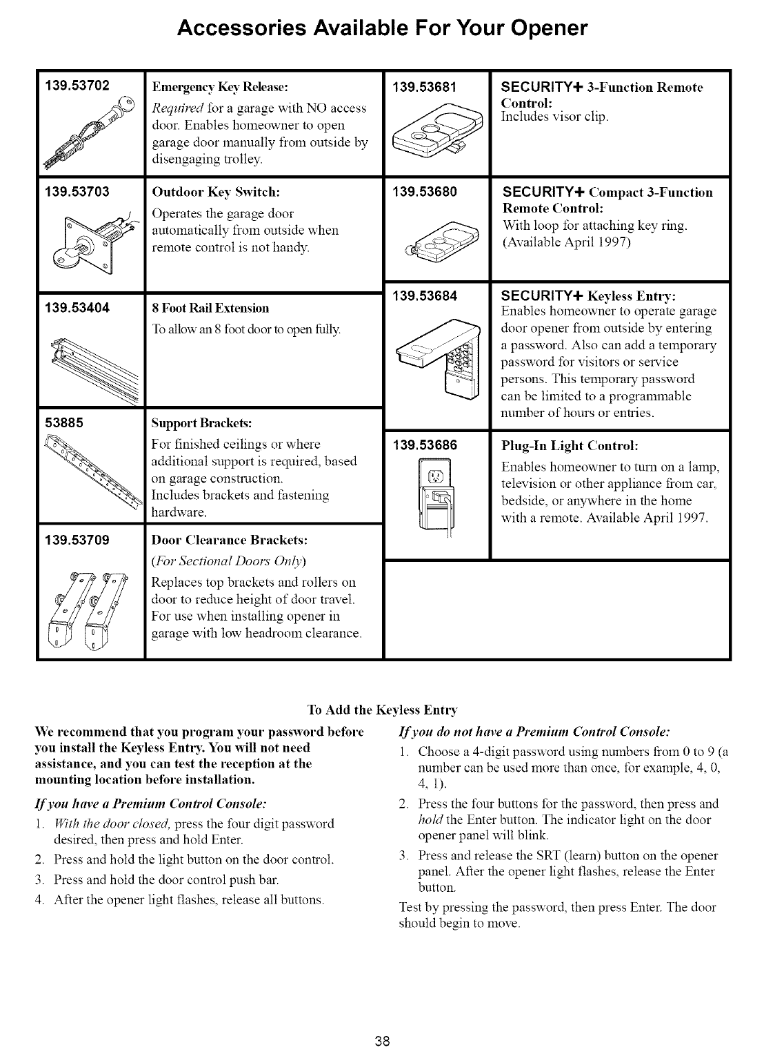
Accessories Available For Your Opener
139.53702
/
139.53703
139.53404
53885
139.53709
Emergency Key Release:
Requ#vd for a garage with NO access
door. Enables homeowner to open
garage door lnanually froln omside by
disengaging trolley.
Outdoor Key Switch:
Operates the garage door
amomatically from ontside when
relnote control is not handy.
8Foot Rail Extension
To allow au 8 foot door to open fatly.
Support Brackets:
For finished ceilings or where
additional support is required, based
on garage construction.
Includes brackets and fastening
hardware.
Door Clearance Brackets:
(For Sectional Dools' Only)
Replaces top brackets and rollers on
door to rednce height of door travel.
For use when installing opener in
garage with low headroom clearance.
139.53681
139.53680
139.53684
SECURITY+ 3-Function Remote
Control:
Includes visor clip.
SECURITY+ Compact 3-Function
Remote Control:
With loop for attaching key ring.
(Available April 1997)
SECURITY+ Keyless Entry:
Enables holneowner to operate garage
door opener froln omside by entering
a password. Also can add a temporary
password for visitors or service
persons. This temporary password
can be limited to a progralnmable
nulnber of hours or entries.
139.53686 Plug-In Light Control:
Enables homeowner to tnrn on a lamp,
television or other appliance from car,
bedside, or anywhere in the home
with a relnote. Available April 1997.
To Add the Keyless Entl T
We recommend that you program your password before
you install the Keyless Entl T. You wiU not need
assistance, and you can test the reception at the
mounting location before installation.
If you have a Premium Control Console:
1. With the door closed, press the four digit password
desired, then press and hold Enter.
2. Press and hold the light button on the door control.
3. Press and hold the door control push bar.
4. After the opener light flashes, release all buttons.
If you do not have a Premium Control Console:
1. Choose a 4-digit password using numbers i]oln 0 to 9 (a
number can be used more than once, for example, 4, 0,
4, 1).
2. Press the four buttons for the password, then press and
hold the Enter button. The indicator light on the door
opener panel will blink.
3. Press and release the SRT (learn) button on the opener
panel. After the opener light flashes, release the Enter
button.
Test by pressing the password, then press Enter. The door
should begin to move.
38
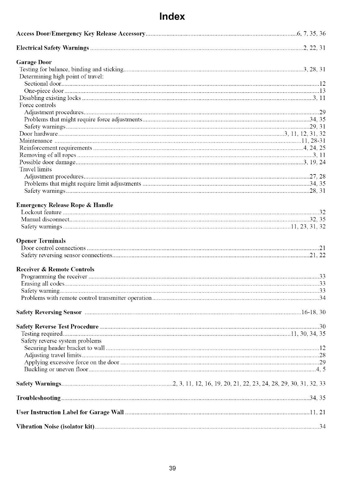
Index
Access Door/Emergency Key Release Accesso_" ............................................................................................... 6, 7, 35, 36
Electrical SafeD" Warnings ...................................................................................................................................... 2, 22, 31
Garage Door
Testing for balance, binding and sticking ................................................................................................................. 3, 28, 31
Determining high point of travel:
Sectional door .................................................................................................................................................................. 12
One-piece door ................................................................................................................................................................ 13
Disabling existing locks ................................................................................................................................................. 3, 11
Force controls
Adjustlnem procednres .................................................................................................................................................... 29
Problems that might require force adjustlnents ......................................................................................................... 34, 35
Safety warnings ......................................................................................................................................................... 29, 31
Door hardware .............................................................................................................................................. 3, 11, 12, 31, 32
Maintenance ........................................................................................................................................................... 11, 28-31
Reinforcelnent requirements .................................................................................................................................... 4, 24, 25
Relnoving of all ropes .................................................................................................................................................... 3, 11
Possible door damage ............................................................................................................................................... 3, 19, 24
Travel limits
Adjustlnent procedures .............................................................................................................................................. 27, 28
Problems that might require limit adjustlnents ......................................................................................................... 34, 35
Safety warnings ......................................................................................................................................................... 28, 31
Emergency Release Rope & Handle
Lockout feature ................................................................................................................................................................. 32
Manual discom_ect ....................................................................................................................................................... 32, 35
Safety warnings ............................................................................................................................................... 11, 23, 31, 32
Opener Terminals
Door control connections .................................................................................................................................................. 21
Safety reversing sensor connections ............................................................................................................................ 21, 22
Receiver & Remote Controls
Progralrnning the receiver ................................................................................................................................................. 33
Erasing all codes ................................................................................................................................................................ 33
Safety warning ................................................................................................................................................................... 33
Problems with remote control transmitter operation ......................................................................................................... 34
Safety Reversing Sensor ........................................................................................................................................ 16-18, 30
Safety Reverse Test Procedure .......................................................................................................................................... 30
Testing required ............................................................................................................................................... 1t, 30, 34, 35
Safety reverse system problems
Securing header bracket to wall ...................................................................................................................................... 12
Adjusting travel limits ..................................................................................................................................................... 28
Applying excessive force on the door ............................................................................................................................. 29
Buckling or uneven floor ............................................................................................................................................... 4, 5
Safety Warnings ...................................................................... 2, 3, 11, 12, 16, 19, 20, 21, 22, 23, 24, 28, 29, 30, 31, 32, 33
Troubleshooting ............................................................................................................................................................ 34, 35
User Instruction Label for Garage Wall .................................................................................................................... 11, 21
Vibration Noise (isolator kit) ............................................................................................................................................. 34
39

For professional installation
Call 24 hours a day, 7 days a week
1-800-865-6500
For the repair or replacement parts you need
Call 7 am - 7 pm, 7 days a week
1-800-366-PART
(1-800-366-7278)
For in-home major brand repair service
Call 24 hours a day, 7 days a week
1-800-4-RE PA I R
(1-800-473-7247)
For the location of a Sears Repair Service Center in your area
Call 24 hours a day, 7 days a week
1-800-488-1 222
For information on purchasing a Sears Maintenance Agreement
or to inquire about an existing Agreement
Call 9 am - 5 pm, Monday-Saturday
1-800-827-6655
m
|l BII|EE
The model number label is located under the light lens on the
front end panel of your opener. When requesting service or
ordering parts, always give the following information:
• Product Type
• Model Number
• Part Number
•Part Description
r-3
SEARS WARRANTY
FULL 90-DAY WARRANTY ON GARAGE DOOR OPENER
For 90 days from the date of purchase, Sears will repair this Garage Door Opener, free of charge, if defective in material or
workmanship.
LIMITED WARRANTY
From the 91st day untiI one year from the date of purchase, Sears will furnish replacement parts for any defective parts, free of charge.
You pay for labor.
LIMITED WARRANTY ON MOTOR
I/2HP MOTOR: After 1 year and through 5 years, if the motor on this Garage Door Opener is defective, Sears will furnish a replacement
motor, free of charge. You pay for labor.
LIMITATION ON LIABILITY
SEARS WILL NOT BE LIABLE FOR LOSS OR DAMAGE TO PROPERTY OR ANY INCIDENTAL OR CONSEQUENTIAL LOSS OR
EXPENSE FROM PROPERTY DAMAGE DUE DIRECTLY OR INDIRECTLY FROM THE USE OF THIS PRODUCT. Some states do
not allow the exclusion or limitation of incidental or consequential damages, so the above limitation or exclusion may not apply to you.
This warranty does not cover light bulbs or repair parts necessary because of operator abuse or negligence, including the failure to
install, adjust and operate this garage door opener according to instructions contained in the owner's manual.
WARRANTY SERVICE IS AVAILABLE BY SIMPLY CONTACTING THE NEAREST SEARS CENTER/DEPARTMENT IN THE UNITED
STATES.
This warranty applies only while this product is in use in the United States.
This warranty gives you specific legal rights, and you may also have other rights which vary from state to state.
Sears, Roebuck and Co., Dept. 817WA, Hoffman Estates, IL 60179
r-3
114A2123 @1996, All Rights Reserved Printed in Mexico
